Embed Size (px)
Citation preview
http://www.instructables.com/id/LED-Cube-4x4x4/
Home Sign Up! Browse Community Submit
All Art Craft Food Games Green Home Kids Life Music Offbeat Outdoors Pets Photo Ride Science Tech
LED Cube 4x4x4by chr on March 24, 2008
Table of Contents
LED Cube 4x4x4 . . . . . . . . . . . . . . . . . . . . . . . . . . . . . . . . . . . . . . . . . . . . . . . . . . . . . . . . . . . . . . . . . . . . . . . . . . . . . . . . . . . . . . . . . . . . . . . . . . . . . . . . . . . . . . 1
Intro: LED Cube 4x4x4 . . . . . . . . . . . . . . . . . . . . . . . . . . . . . . . . . . . . . . . . . . . . . . . . . . . . . . . . . . . . . . . . . . . . . . . . . . . . . . . . . . . . . . . . . . . . . . . . . . . . . . 2
Step 1: What you need . . . . . . . . . . . . . . . . . . . . . . . . . . . . . . . . . . . . . . . . . . . . . . . . . . . . . . . . . . . . . . . . . . . . . . . . . . . . . . . . . . . . . . . . . . . . . . . . . . . . . . 3
Step 2: Multiplexing . . . . . . . . . . . . . . . . . . . . . . . . . . . . . . . . . . . . . . . . . . . . . . . . . . . . . . . . . . . . . . . . . . . . . . . . . . . . . . . . . . . . . . . . . . . . . . . . . . . . . . . . . 3
Step 3: Making the cube, template . . . . . . . . . . . . . . . . . . . . . . . . . . . . . . . . . . . . . . . . . . . . . . . . . . . . . . . . . . . . . . . . . . . . . . . . . . . . . . . . . . . . . . . . . . . . . . 4
Step 4: Making the cube, solder the layers . . . . . . . . . . . . . . . . . . . . . . . . . . . . . . . . . . . . . . . . . . . . . . . . . . . . . . . . . . . . . . . . . . . . . . . . . . . . . . . . . . . . . . . . 5
Step 5: Making the cube, connecting the layers . . . . . . . . . . . . . . . . . . . . . . . . . . . . . . . . . . . . . . . . . . . . . . . . . . . . . . . . . . . . . . . . . . . . . . . . . . . . . . . . . . . . 7
Step 6: Choosing resistor values . . . . . . . . . . . . . . . . . . . . . . . . . . . . . . . . . . . . . . . . . . . . . . . . . . . . . . . . . . . . . . . . . . . . . . . . . . . . . . . . . . . . . . . . . . . . . . . 9
Step 7: The controller . . . . . . . . . . . . . . . . . . . . . . . . . . . . . . . . . . . . . . . . . . . . . . . . . . . . . . . . . . . . . . . . . . . . . . . . . . . . . . . . . . . . . . . . . . . . . . . . . . . . . . . 9
Step 8: Wire up the cube . . . . . . . . . . . . . . . . . . . . . . . . . . . . . . . . . . . . . . . . . . . . . . . . . . . . . . . . . . . . . . . . . . . . . . . . . . . . . . . . . . . . . . . . . . . . . . . . . . . . . 11
Step 9: Compile and program . . . . . . . . . . . . . . . . . . . . . . . . . . . . . . . . . . . . . . . . . . . . . . . . . . . . . . . . . . . . . . . . . . . . . . . . . . . . . . . . . . . . . . . . . . . . . . . . . 12
File Downloads . . . . . . . . . . . . . . . . . . . . . . . . . . . . . . . . . . . . . . . . . . . . . . . . . . . . . . . . . . . . . . . . . . . . . . . . . . . . . . . . . . . . . . . . . . . . . . . . . . . . . . . . . . . 12
Step 10: Program the microcontroller . . . . . . . . . . . . . . . . . . . . . . . . . . . . . . . . . . . . . . . . . . . . . . . . . . . . . . . . . . . . . . . . . . . . . . . . . . . . . . . . . . . . . . . . . . . . 12
Step 11: Go large - 8x8x8 . . . . . . . . . . . . . . . . . . . . . . . . . . . . . . . . . . . . . . . . . . . . . . . . . . . . . . . . . . . . . . . . . . . . . . . . . . . . . . . . . . . . . . . . . . . . . . . . . . . . 14
Related Instructables . . . . . . . . . . . . . . . . . . . . . . . . . . . . . . . . . . . . . . . . . . . . . . . . . . . . . . . . . . . . . . . . . . . . . . . . . . . . . . . . . . . . . . . . . . . . . . . . . . . . . . . . 15
Comments . . . . . . . . . . . . . . . . . . . . . . . . . . . . . . . . . . . . . . . . . . . . . . . . . . . . . . . . . . . . . . . . . . . . . . . . . . . . . . . . . . . . . . . . . . . . . . . . . . . . . . . . . . . . . . . . 15
http://www.instructables.com/id/LED-Cube-4x4x4/
Author:chrI like microcontrollers and LEDs :D
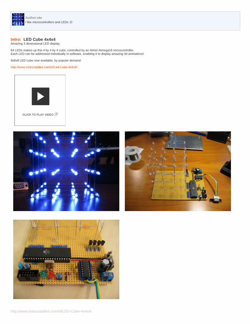
Intro: LED Cube 4x4x4Amazing 3 dimensional LED display.
64 LEDs makes up this 4 by 4 by 4 cube, controlled by an Atmel Atmega16 microcontroller.Each LED can be addressed individually in software, enabling it to display amazing 3d animations!
8x8x8 LED cube now available, by popular demand:
http://www.instructables.com/id/Led-Cube-8x8x8/
http://www.instructables.com/id/LED-Cube-4x4x4/
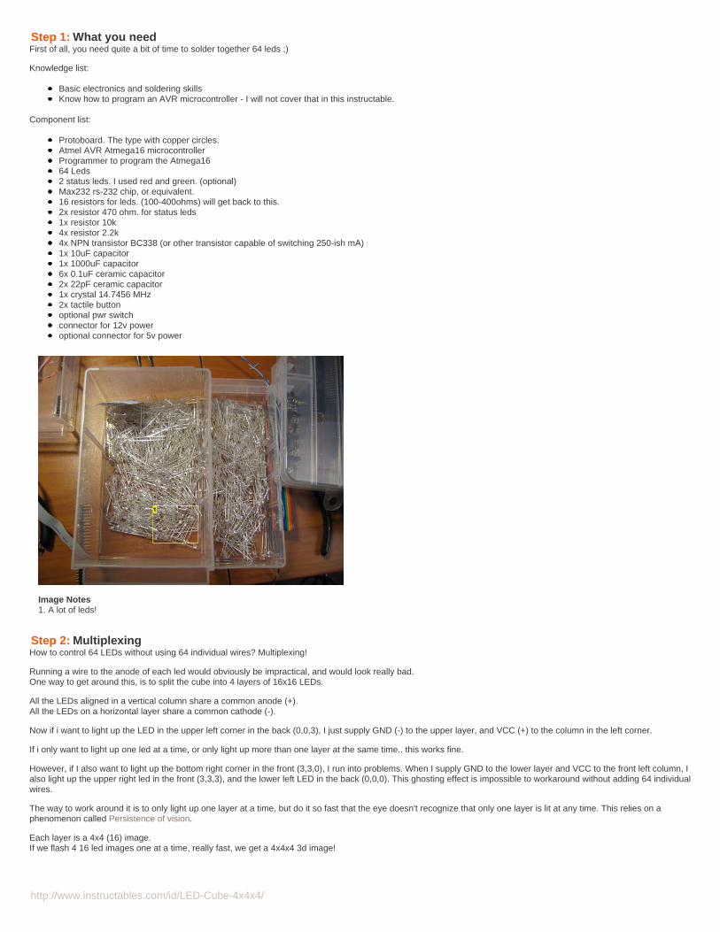
Step 1: What you needFirst of all, you need quite a bit of time to solder together 64 leds ;)
Knowledge list:
Basic electronics and soldering skillsKnow how to program an AVR microcontroller - I will not cover that in this instructable.
Component list:
Protoboard. The type with copper circles.Atmel AVR Atmega16 microcontrollerProgrammer to program the Atmega1664 Leds2 status leds. I used red and green. (optional)Max232 rs-232 chip, or equivalent.16 resistors for leds. (100-400ohms) will get back to this.2x resistor 470 ohm. for status leds1x resistor 10k4x resistor 2.2k4x NPN transistor BC338 (or other transistor capable of switching 250-ish mA)1x 10uF capacitor1x 1000uF capacitor6x 0.1uF ceramic capacitor2x 22pF ceramic capacitor1x crystal 14.7456 MHz2x tactile buttonoptional pwr switchconnector for 12v poweroptional connector for 5v power
Image Notes1. A lot of leds!
Step 2: MultiplexingHow to control 64 LEDs without using 64 individual wires? Multiplexing!
Running a wire to the anode of each led would obviously be impractical, and would look really bad.One way to get around this, is to split the cube into 4 layers of 16x16 LEDs.
All the LEDs aligned in a vertical column share a common anode (+).All the LEDs on a horizontal layer share a common cathode (-).
Now if i want to light up the LED in the upper left corner in the back (0,0,3), I just supply GND (-) to the upper layer, and VCC (+) to the column in the left corner.
If i only want to light up one led at a time, or only light up more than one layer at the same time.. this works fine.
However, if I also want to light up the bottom right corner in the front (3,3,0), I run into problems. When I supply GND to the lower layer and VCC to the front left column, Ialso light up the upper right led in the front (3,3,3), and the lower left LED in the back (0,0,0). This ghosting effect is impossible to workaround without adding 64 individualwires.
The way to work around it is to only light up one layer at a time, but do it so fast that the eye doesn't recognize that only one layer is lit at any time. This relies on aphenomenon called Persistence of vision.
Each layer is a 4x4 (16) image.If we flash 4 16 led images one at a time, really fast, we get a 4x4x4 3d image!
http://www.instructables.com/id/LED-Cube-4x4x4/
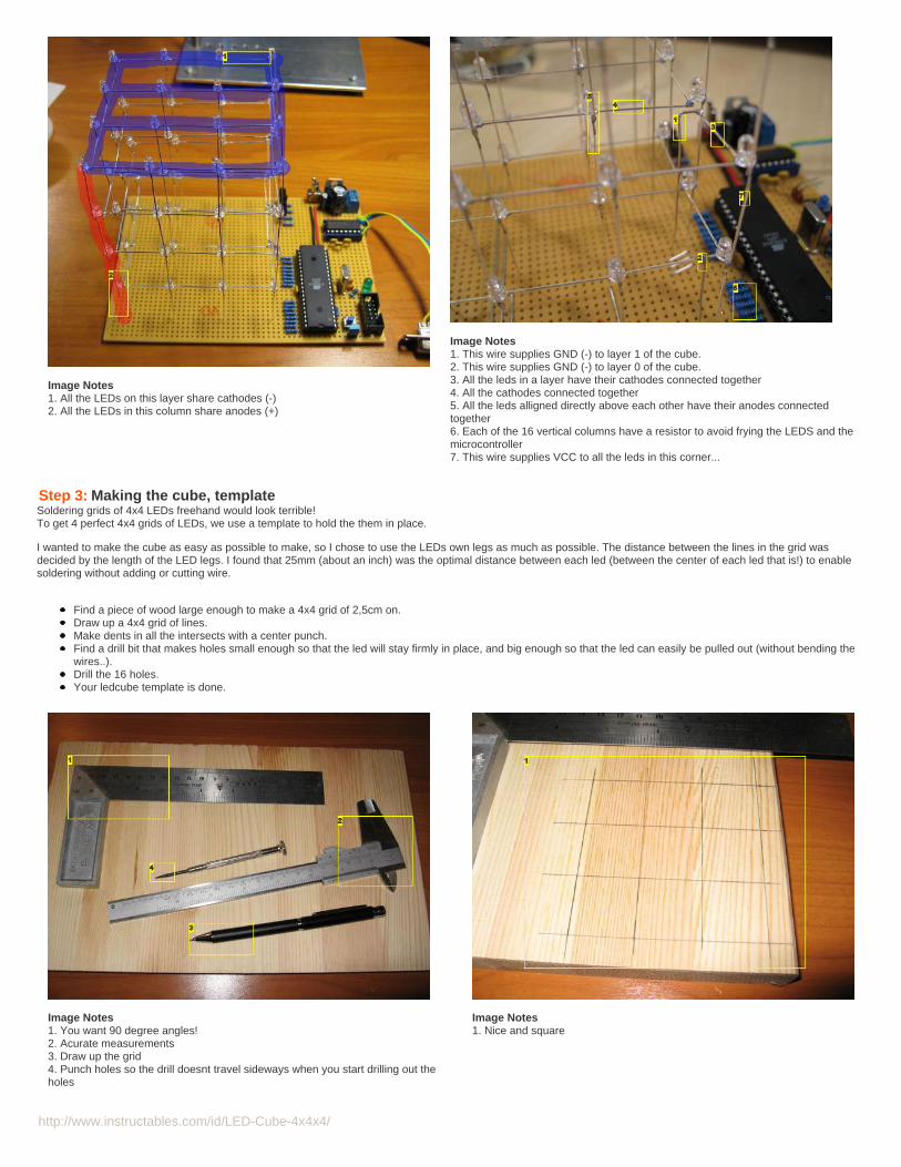
Image Notes1. All the LEDs on this layer share cathodes (-)2. All the LEDs in this column share anodes (+)
Image Notes1. This wire supplies GND (-) to layer 1 of the cube.2. This wire supplies GND (-) to layer 0 of the cube.3. All the leds in a layer have their cathodes connected together4. All the cathodes connected together5. All the leds alligned directly above each other have their anodes connectedtogether6. Each of the 16 vertical columns have a resistor to avoid frying the LEDS and themicrocontroller7. This wire supplies VCC to all the leds in this corner...
Step 3: Making the cube, templateSoldering grids of 4x4 LEDs freehand would look terrible!To get 4 perfect 4x4 grids of LEDs, we use a template to hold the them in place.
I wanted to make the cube as easy as possible to make, so I chose to use the LEDs own legs as much as possible. The distance between the lines in the grid wasdecided by the length of the LED legs. I found that 25mm (about an inch) was the optimal distance between each led (between the center of each led that is!) to enablesoldering without adding or cutting wire.
Find a piece of wood large enough to make a 4x4 grid of 2,5cm on.Draw up a 4x4 grid of lines.Make dents in all the intersects with a center punch.Find a drill bit that makes holes small enough so that the led will stay firmly in place, and big enough so that the led can easily be pulled out (without bending thewires..).Drill the 16 holes.Your ledcube template is done.
Image Notes1. You want 90 degree angles!2. Acurate measurements3. Draw up the grid4. Punch holes so the drill doesnt travel sideways when you start drilling out theholes
Image Notes1. Nice and square
http://www.instructables.com/id/LED-Cube-4x4x4/
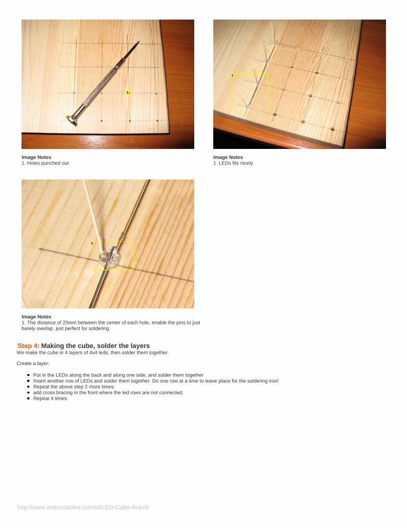
Image Notes1. Holes punched out
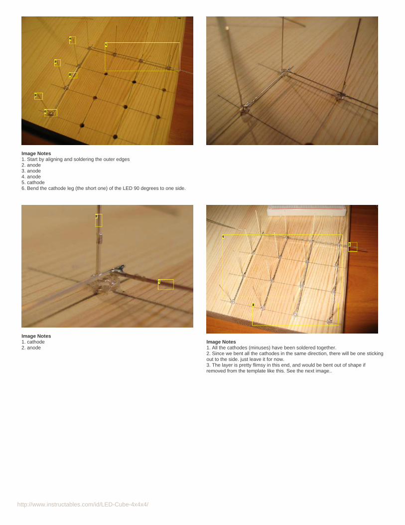
Image Notes1. LEDs fits nicely
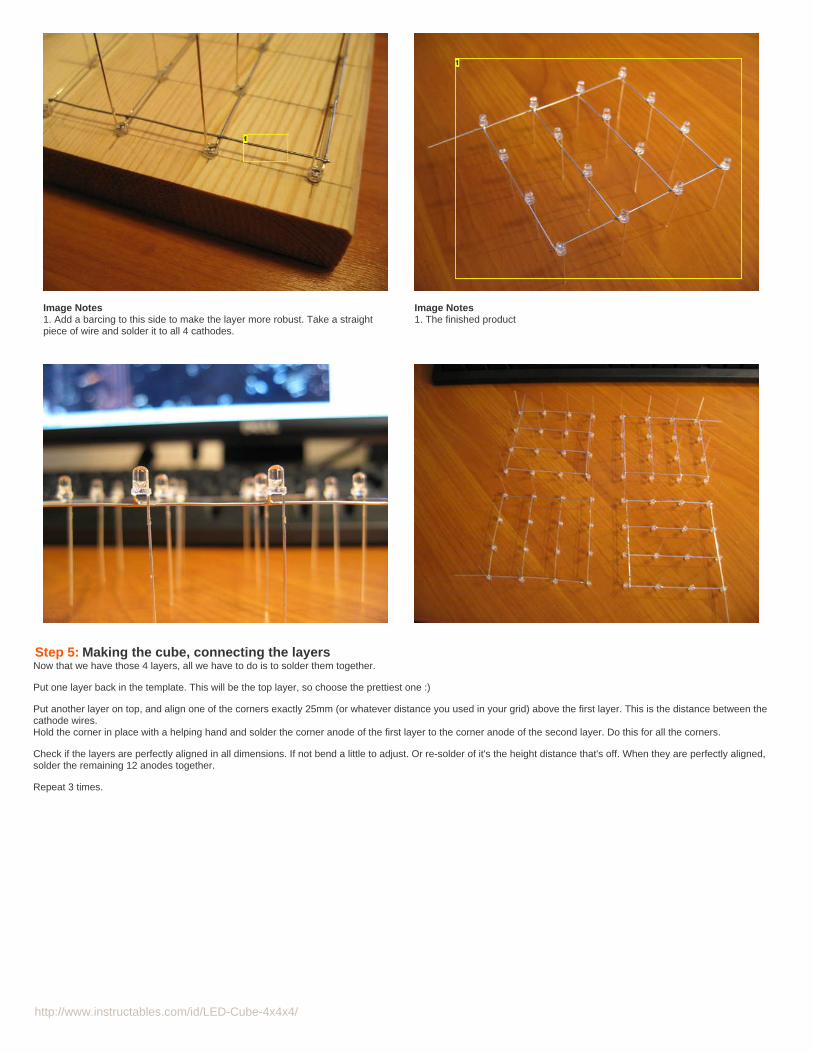
Image Notes1. The distance of 25mm between the center of each hole, enable the pins to justbarely overlap. just perfect for soldering.
Step 4: Making the cube, solder the layersWe make the cube in 4 layers of 4x4 leds, then solder them together.
Create a layer:
Put in the LEDs along the back and along one side, and solder them togetherInsert another row of LEDs and solder them together. Do one row at a time to leave place for the soldering iron!Repeat the above step 2 more times.add cross bracing in the front where the led rows are not connected.Repeat 4 times.
http://www.instructables.com/id/LED-Cube-4x4x4/
Image Notes1. Start by aligning and soldering the outer edges2. anode3. anode4. anode5. cathode6. Bend the cathode leg (the short one) of the LED 90 degrees to one side.
Image Notes1. cathode2. anode
Image Notes1. All the cathodes (minuses) have been soldered together.2. Since we bent all the cathodes in the same direction, there will be one stickingout to the side. just leave it for now.3. The layer is pretty flimsy in this end, and would be bent out of shape ifremoved from the template like this. See the next image..
http://www.instructables.com/id/LED-Cube-4x4x4/
Image Notes1. Add a barcing to this side to make the layer more robust. Take a straightpiece of wire and solder it to all 4 cathodes.
Image Notes1. The finished product
Step 5: Making the cube, connecting the layersNow that we have those 4 layers, all we have to do is to solder them together.
Put one layer back in the template. This will be the top layer, so choose the prettiest one :)
Put another layer on top, and align one of the corners exactly 25mm (or whatever distance you used in your grid) above the first layer. This is the distance between thecathode wires.Hold the corner in place with a helping hand and solder the corner anode of the first layer to the corner anode of the second layer. Do this for all the corners.
Check if the layers are perfectly aligned in all dimensions. If not bend a little to adjust. Or re-solder of it's the height distance that's off. When they are perfectly aligned,solder the remaining 12 anodes together.
Repeat 3 times.
http://www.instructables.com/id/LED-Cube-4x4x4/
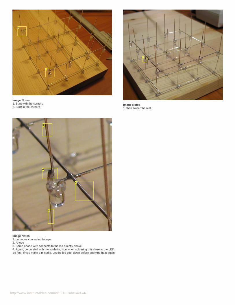
Image Notes1. Start with the corners2. Start in the corners
Image Notes1. then solder the rest.
Image Notes1. cathodes connected to layer2. Anode3. Same anode wire connects to the led directly above..4. Again, be carefull with the soldering iron when soldering this close to the LED.Be fast. If you make a mistake. Let the led cool down before applying heat again.
http://www.instructables.com/id/LED-Cube-4x4x4/
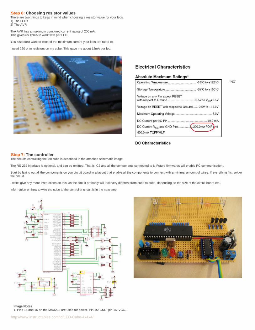
Step 6: Choosing resistor valuesThere are two things to keep in mind when choosing a resistor value for your leds.1) The LEDs2) The AVR
The AVR has a maximum combined current rating of 200 mA.This gives us 12mA to work with per LED.
You also don't want to exceed the maximum current your leds are rated to.
I used 220 ohm resistors on my cube. This gave me about 12mA per led.
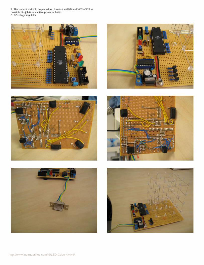
Step 7: The controllerThe circuits controlling the led cube is described in the attached schematic image.
The RS-232 interface is optional. and can be omitted. That is IC2 and all the components connected to it. Future firmwares will enable PC communication..
Start by laying out all the components on you circuit board in a layout that enable all the components to connect with a minimal amount of wires. If everything fits, solderthe circuit.
I won't give any more instructions on this, as the circuit probably will look very different from cube to cube, depending on the size of the circuit board etc..
Information on how to wire the cube to the controller circuit is in the next step.
Image Notes1. Pins 15 and 16 on the MAX232 are used for power. Pin 15: GND, pin 16: VCC.
http://www.instructables.com/id/LED-Cube-4x4x4/
2. This capacitor should be placed as close to the GND and VCC of IC2 aspossible. It's job is to stabilize power to that ic.3. 5V voltage regulator
http://www.instructables.com/id/LED-Cube-4x4x4/
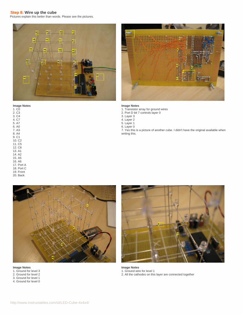
Step 8: Wire up the cubePictures explain this better than words. Please see the pictures.
Image Notes1. C02. C33. C44. C75. A76. A07. A38. A49. C110. C211. C512. C613. A114. A215. A516. A617. Port A18. Port C19. Front20. Back
Image Notes1. Transistor array for ground wires2. Port D bit 7 controls layer 03. Layer 34. Layer 25. Layer 16. Layer 07. Yes this is a picture of another cube. I didn't have the original available whenwriting this.
Image Notes1. Ground for level 32. Ground for level 23. Ground for level 14. Ground for level 0
Image Notes1. Ground wire for level 12. All the cathodes on this layer are connected together
http://www.instructables.com/id/LED-Cube-4x4x4/
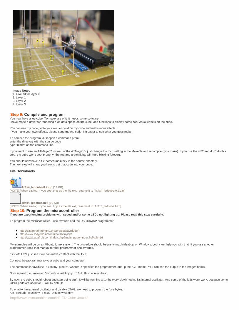
Image Notes1. Ground for layer 02. Layer 13. Layer 24. Layer 3
Step 9: Compile and programYou now have a led cube. To make use of it, it needs some software.I have made a driver for rendering a 3d data space on the cube, and functions to display some cool visual effects on the cube.
You can use my code, write your own or build on my code and make more effects.If you make your own effects, please send me the code. I'm eager to see what you guys make!
To compile the program. Just open a command promt,enter the directory with the source codetype "make" on the command line.
If you want to use an ATMega32 instead of the ATMega16, just change the mcu setting in the Makefile and recompile (type make). If you use the m32 and don't do thisstep, the cube won't boot properly (the red and green lights will keep blinking forever).
You should now have a file named main.hex in the source directory.The next step will show you how to get that code into your cube.
File Downloads
4x4x4_ledcube-0.2.zip (14 KB)[NOTE: When saving, if you see .tmp as the file ext, rename it to '4x4x4_ledcube-0.2.zip']
4x4x4_ledcube.hex (19 KB)[NOTE: When saving, if you see .tmp as the file ext, rename it to '4x4x4_ledcube.hex']
Step 10: Program the microcontrollerIf you are experiencing problems with speed and/or some LEDs not lighting up. Please read this step carefully.
To program the microcontroller, I use avrdude and the USBTinyISP programmer.
http://savannah.nongnu.org/projects/avrdude/http://www.ladyada.net/make/usbtinyisp/http://www.adafruit.com/index.php?main_page=index&cPath=16
My examples will be on an Ubuntu Linux system. The procedure should be pretty much identical on Windows, but I can't help you with that. If you use anotherprogrammer, read thet manual for that programmer and avrdude.
First off, Let's just see if we can make contact with the AVR.
Connect the programmer to your cube and your computer.
The command is "avrdude -c usbtiny -p m16", wherer -c specifies the programmer, and -p the AVR model. You can see the output in the images below.
Now, upload the firmware: "avrdude -c usbtiny -p m16 -U flash:w:main.hex".
By now, the cube should reboot and start doing stuff. It will be running at 1mhz (very slowly) using it's internal oscillator. And some of the leds won't work, because someGPIO ports are used for JTAG by default.
To enable the external oscillator and disable JTAG, we need to program the fuse bytes:run "avrdude -c usbtiny -p m16 -U lfuse:w:0xef:m"

http://www.instructables.com/id/LED-Cube-4x4x4/
and "avrdude -c usbtiny -p m16 -U hfuse:w:0xc9:m".
Be carefull when doing this step! If you get it wrong, you can permanently destroy your microcontroller! If you are using another microcontroller than the ATMega16, besure to read the datasheet carefully before changing the fuse bytes!
After writing the correct fuse bytes, the cube should reboot and start operating at regular speed with all leds operational.
Enjoy your new cube :D
Image Notes1. Success2. Check if programmer and uC can communicate
Image Notes1. Write firmware If you downloaded the file 4x4x4_ledcube.hex, it should be -U flash:w:4x4x4_ledcube.hex2. 9KB to spare! You have lot's of space to write new effects or storeanimations.
Image Notes1. Write lower fuse bits
Image Notes1. Write higher fuse bits
http://www.instructables.com/id/LED-Cube-4x4x4/
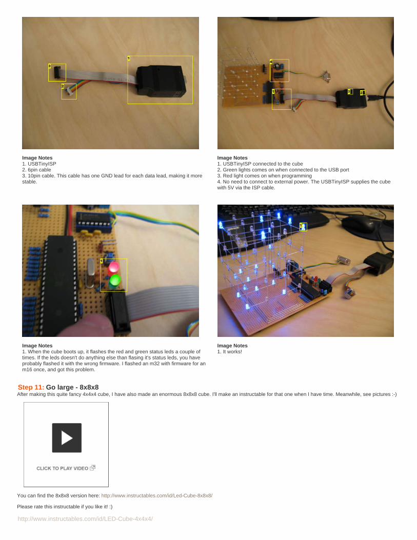
Image Notes1. USBTinyISP2. 6pin cable3. 10pin cable. This cable has one GND lead for each data lead, making it morestable.
Image Notes1. USBTinyISP connected to the cube2. Green lights comes on when connected to the USB port3. Red light comes on when programming4. No need to connect to external power. The USBTinyISP supplies the cubewith 5V via the ISP cable.
Image Notes1. When the cube boots up, it flashes the red and green status leds a couple oftimes. If the leds doesn't do anything else than flasing it's status leds, you haveprobably flashed it with the wrong firmware. I flashed an m32 with firmware for anm16 once, and got this problem.
Image Notes1. It works!
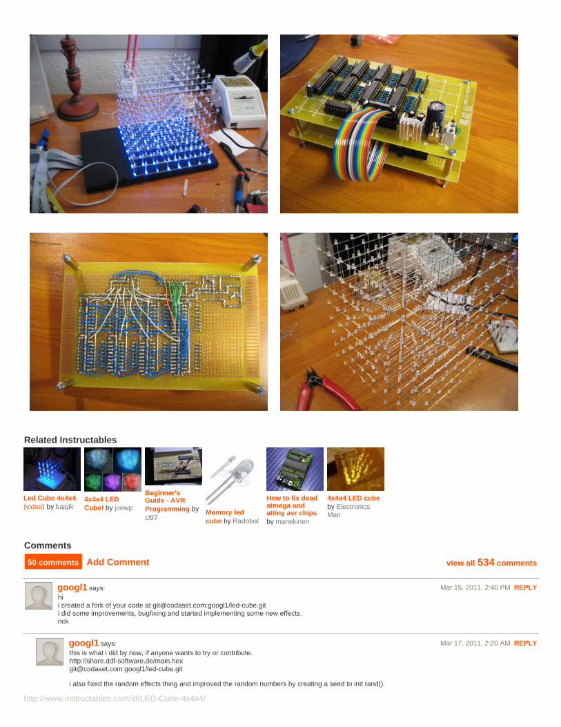
Step 11: Go large - 8x8x8After making this quite fancy 4x4x4 cube, I have also made an enormous 8x8x8 cube. I'll make an instructable for that one when I have time. Meanwhile, see pictures :-)
You can find the 8x8x8 version here: http://www.instructables.com/id/Led-Cube-8x8x8/
Please rate this instructable if you like it! :)
http://www.instructables.com/id/LED-Cube-4x4x4/
Related Instructables
Led Cube 4x4x4(video) by bajgik
4x4x4 LEDCube! by joewp
Beginner'sGuide - AVRProgramming bycl97
Memory ledcube by Radobot
How to fix deadatmega andattiny avr chipsby manekinen
4x4x4 LED cubeby ElectronicsMan
Comments
50 comments Add Comment view all 534 comments
googl1 says: Mar 15, 2011. 2:40 PM REPLYhii created a fork of your code at [email protected]:googl1/led-cube.giti did some improvements, bugfixing and started implementing some new effects.rick
googl1 says: Mar 17, 2011. 2:20 AM REPLYthis is what i did by now, if anyone wants to try or contribute.http://share.ddf-software.de/[email protected]:googl1/led-cube.git
i also fixed the random effects thing and improved the random numbers by creating a seed to init rand()

http://www.instructables.com/id/LED-Cube-4x4x4/
rick
coppertopneo says: Mar 15, 2011. 11:42 PM REPLYim new at this and i would really like to try this. i dont know much about programming, but if someone could tell me how its connected to compute. and whatprogram to use to flash it would be helpfully. if you could email me thanks. [email protected]
bhodowanic says: Mar 9, 2011. 3:51 PM REPLYWould this work as the Max232 rs-232 chip?
USB To TTL Converter Module cp2102 arm9 max232 max2332
http://cgi.ebay.com/ws/eBayISAPI.dll?ViewItem&item=380319575805#vi-content
Also what programmer did you use?
MonkeySin says: Feb 20, 2011. 5:49 PM REPLYI want to build this SOOO bad but i don't understand how to use most of the electronics here like the microcontroller. Can anyone please suggest a couple ofprojects i can try first to familiarize myself with the micro controller, atmega16 and things like that? or a website where i can learn them? thank you muchappreciated.!!
computurwizard says: Mar 8, 2011. 7:34 PM REPLYSee:http://www.avrfreaks.net/index.php?name=PNphpBB2&file=viewtopic&t=70673
Start with "A From-Scratch AVR Tutorial"
Zaphod Beeblebrox says: Mar 5, 2011. 7:36 AM REPLYi saw these in a hammacher sschlemmer catalog
wmtt says: Mar 4, 2011. 12:01 AM REPLYDear chr, your cube is loved my many.May I ask
1.are the LEDs switching on and off without grayscale? In another word, is PWM used in this cube. It appears to be the case in the video but it may be POVeffect.
2. How fast the layer mutiplexing is, i.e. the refresh rate?
Many thanks.
wmtt
Buskleif says: Mar 3, 2011. 11:56 AM REPLYJust finished building this and it works great.I used the atmega32 instead of the 16, and an avrisp mkII programmer.Running it at 16MHz with no problems.
ricarz16 says: Feb 28, 2011. 1:16 PM REPLYhow can i make the cube faster???
i have a problem with the reprogramming of the atmega16my programmer is not able to find my atmega again!!!
please help me
chris.sevilla says: Feb 26, 2011. 3:51 AM REPLYcan the LED cube be controlled with an Atmel AT89S52 microcontroller??
Steeps5 says: Feb 22, 2011. 12:19 PM REPLYYou may want to add the 10-pin connector for the AVR programmer into the component list. I almost forgot to order it!
wickidude says: Feb 18, 2011. 5:58 AM REPLYHey,Im have two problems i have built this on a PCB which i have designed myself and programmed it and most of the columns work fine its just outputs C2-C5are dim and always on. Also the clock speed is set to the internal clock speed so the program is quite slow how do i set it to the external clock ?
thanks

http://www.instructables.com/id/LED-Cube-4x4x4/
wickidude says: Feb 18, 2011. 4:05 PM REPLYsorrry realised i hadnt set fuse bits works perfectly now
ptorelli says: Feb 13, 2011. 10:14 PM REPLYA clamp-on heatsink will help keep the LED from melting when soldering (clamp it on the 5mm of space between the weld and the bulb). RadioShack sellsthem, looks like a pair of industrial eyebrow tweezers.
febinjohn says: Feb 8, 2011. 3:02 AM REPLYchr ur make file is have some bugs that`s why i got error while compiling the file
makefile:1: *** missing separator. Stop.
its due to error in compression i think any way i made a make file by my own for 32 now everything fine i will post some pics very soon :)
febinjohn says: Jan 21, 2011. 7:28 AM REPLY
I made the cube but not working only the status leds are blinking
i am using mega32 t i can use same fuse as 16 ???
in high only SUT0 is high and in low SPIEN ,BOOTSZ1 and BOOTSZ0 is high
please somebody :-(
chr says: Jan 21, 2011. 7:34 AM REPLYHi,
I think you can use the same fuses, but you have to change the Makefile and recompile the software.
Change this line:MCU = atmega16
To this:MCU = atmega32
If you load the mega32 with firmware compiled for the mega16, it will work long enough for the status leds to blink, then reboot.
Remeber to post pictures and video when you get it working :)
febinjohn says: Feb 1, 2011. 2:14 AM REPLYam getting an errormakefile:1: *** missing separator. Stop.
when i type make :-(or can u post firmware for 32????
thanhnam2k says: Jan 21, 2011. 9:33 AM REPLYHi,
If I use ATMega16L, should I change the crystal 14.7456 MHz to 8Mhz or lower?Is there any other change needed?
BTW, which should be the equivalent to the transistor BC338?I'm looking for the replacement in 2Nxxxx series, is it possible?
Thanks in advance,

http://www.instructables.com/id/LED-Cube-4x4x4/
febinjohn says: Jan 28, 2011. 1:42 AM REPLY2N2222 is working for me
thanhnam2k says: Jan 29, 2011. 2:37 AM REPLYThank you, I'll try it.
Afide says: Jan 25, 2011. 9:36 AM REPLYMan I want to build this so badly, but I don't get the circuit at all, it would be infinitely amazing if someone made a little video of creating it.
domdomgin says: Jan 23, 2011. 12:18 AM REPLYwhere do i have to put the hex file in which directory..i have usbtiny..it cannot locate the hex file to upload the firmware
andrejmdias says: Jan 18, 2011. 1:29 PM REPLYsomeone has the full pdf of this circuit to sendsend: [email protected]
andersop says: Jan 18, 2011. 10:35 AM REPLYHi,I was wandering if it could be possible to get a hi-quality picture of that circuit-sketch?and also; what is the voltage on the capacitors? Is 45V bad? 100v? hard to find 5v...I'm almost ready to start building ;)
shaunak says: Jan 15, 2011. 9:31 PM REPLYThe template is a great Idea and it helps a lot.
bdc1513 says: Jan 13, 2011. 3:24 PM REPLYI'm Planning on building this one, but i'm wondering about how much this entire project will cost. people who have built it, what did it cost you? (if you hadnone of the parts in advanced, except the soldering equipment)
Ryan McDougall says: Jan 13, 2011. 2:49 PM REPLYCould I use 200 ohm resistors instead of 220 ohms for the LEDs
ricarz16 says: Jan 11, 2011. 3:10 PM REPLY=)...it RUNS
zref21 says: Jan 10, 2011. 2:42 PM REPLYGreat Instructable!
Some parts of the schematic had me confused for a while (Okay, maybe i went a little overkill for my 2nd electronics project ever...), but luckily googleprovided some answers :)And, although i had some setbacks during the construction (including one fried ISP programmer because i mounted that 10-pin connector the wrong way...stupid me), my cube is now finished!
One thing still confuses me, though... you setup USART in your code (along with the MAX232 and all...) but you never make use of it.I really want serial communication for my cube, so i wonder: Do you have a working USART implementation for this? Or could you point me to some othertutorial/'ible using USART, so i can start from there?

http://www.instructables.com/id/LED-Cube-4x4x4/
chr says: Jan 10, 2011. 2:59 PM REPLYThanks for the feedback, I love getting pictures :D
I think i tried the rs232 port on this LED cube once.. Just sent random data to it.
The 8x8x8 LED cube has a working rs232 stack. The cube buffer has the same layout, only the cube buffer looks like this:
cube[8][8], and the 4x4x4 cube has cube[4][4].
You only have to change the if() statements to reset to 0,0 when x and y hit 3, not 7.
Download the source code for the 8x8x8 cube and have a look.
zref21 says: Jan 10, 2011. 3:13 PM REPLYthanks, will do!
as soon as i got it running, i'll post a link to the updated code here, so that others can enjoy it as well ^^
for now, i just sit and enjoy watching my cube do stuff :)
cricketm24 says: Jan 9, 2011. 6:56 PM REPLYyou don't have all your componets that are on your board on your list like the connecter for the programmer can you please give the full list
hobbyman says: Jan 8, 2011. 2:06 PM REPLYpainting the leads to black might improve the quality of the produced graphics in the cube I guess.
cricketm24 says: Jan 6, 2011. 5:19 PM REPLYcan anyone tell me how to program the chip and what software to use
samirsky says: Jan 6, 2011. 12:51 PM REPLYJust saw the 8x8x8. Awesome!
Do you have any new or other patterns/software for the 4x4x4?
michalfiasky says: Jan 4, 2011. 4:52 AM REPLYsomeone send me instructions on how to put together? Please. send me an email [email protected] I am from Slovakia and my English is not perfectand therefore I'm sorry.
Kartoffelpuffer says: Dec 25, 2010. 8:00 AM REPLYAwesome!!! Great 'ible!!!
I want to build one myself.I've nearly got all parts, only the LED's are missing.Which LED's did you use?I'd especially like to know what angle of radiation your LED's have, and how strong they are!
Thx

http://www.instructables.com/id/LED-Cube-4x4x4/
frollard says: Jan 1, 2011. 4:37 AM REPLYFor a project like this you want any 20ma superbright led (you'll be running it at lower power unless you use a driver) -- and I prefer 'straw hat' leds, orthe concave lens leds --
Straw hat has the lens immediately at the diode portion, so it radiates 180 degrees, where the indented ones (look like they have a cone-divot in the tip)are designed to shoot more light out the sides than out the tip. Saves having to diffuse them.
andyzug says: Dec 17, 2010. 9:06 AM REPLYHi! how I can programm this cube with arduino??THX
domdomgin says: Dec 14, 2010. 7:25 AM REPLYi finished the project but some leds dont light vertically for eg 1 / 11..please suggest..the leds are fine..
kahangkatumbal says: Dec 11, 2010. 5:21 AM REPLYHI! i just wanna ask if this is also applicable with PIC16F84A??
maewert says: Dec 9, 2010. 7:34 PM REPLYMy daughter and I just finished our 5x5x5 cube:
emihackr97 says: Dec 10, 2010. 8:39 AM REPLYHow did you make that, did you use a normal Arduino or an Arduino Mega??
maewert says: Dec 10, 2010. 12:10 PM REPLYWe used a normal 'arduino', specifically an Ardweeny. We used the lower 5 bits of PortD and 5 PNP transistors to supply the power to 5 LEDs at timeand we used the lower 5 bits of PortB to select one of the 25 'columns' to supply the ground to the LEDs. To demultiplex the 5 portB bits into 25individual grounds I used four 74LS138's. The 74LS138 sets one of 8 outputs to ground based on how the three input bits are set. Unfortunately Ireally needed one of the 25 wires set high while all the others were left low when scanning the columns. To accomplish this I had to use 6 hexinverter chips, 74LS04's. I've seen other circuits that used shift registers (like the circuit used in this instructable) but I like the discrete componentssince they are easier to teach:-) Anyway, great fun for a geeky father/daughter project
emihackr97 says: Dec 10, 2010. 6:36 PM REPLYwow, could you post an 'ible on how to make it?? It would be great!
karyochi says: Dec 6, 2010. 5:57 AM REPLYi'm having some problems, when i use the make command, it responds with:"makefile: ***missing seperator", could someone plz help?, i want to use anATmega8 or ATmega32, maybe somoene just could send me the HEX code, [email protected].
capanuwa says: Dec 4, 2010. 9:14 PM REPLYi ,ve made the cube.it's grate.friend can you give us 8x8x8 led cube schematic and the code?pleaseplease please?you are a grate manthanks for the 4x4x4 cube

http://www.instructables.com/id/LED-Cube-4x4x4/
yasoo716 says: Dec 2, 2010. 10:53 AM REPLYdude u are ultimate .....and hats off for your patients for explaining this............
view all 534 comments