Embed Size (px)
Citation preview

15/03/1430
1
Lecture(3)chapter2.2

15/03/1430
2
Coordinate System 1
• Latitude: Angular distance measured in• Latitude: Angular distance, measured in degrees, north or south of the equator.
L from ‐90 to +90 (or from 90S to 90N)
• Longitude: Angular distance, measured in degrees, from a given reference
4
g , glongitudinal line (Greenwich, London).
l from 0 to 360E (or 180W to 180E)

15/03/1430
3
Coordinate System 2
5(Source: M.Richaria, Satellite Communication Systems, Fig.2.9)

15/03/1430
4
LOOK ANGLES 1
• Azimuth:Measured eastward (clockwise)• Azimuth:Measured eastward (clockwise) from geographic north to the projection of the satellite path on a (locally) horizontal plane at the earth station.
• Elevation Angle:Measured upward from
7
the local horizontal plane at the earth station to the satellite path.

15/03/1430
5

15/03/1430
6
El = ψ ‐ 90o
γ = central angle
rs = radius to the satellite
re = radius of the earth
Geometry for Elevation Calculation

15/03/1430
7
Satellite Coordinates
• SUB‐SATELLITE POINTSU S O– Latitude Ls– Longitude ls
• EARTH STATION LOCATION– Latitude Le– Longitude le
• Calculate γ, ANGLE AT EARTH CENTER
13
Between the line that connects the earth‐center to the satellite and the line from the earth‐center to the earth station.
Slant path geometry
sinsinsincC
bB
aA
==Ca
• Review of plane trigonometry– Law of Sines
– Law of Cosines
• Review of spherical trigonometry– Law of Sines
Law of Cosines for angles
( )( )( ) 2
,2
tan
cos2222
cbadcdd
bdadC
Cabbaccba
++=
−−−
=
−+=
CBA sinsinsin
cA
B
ab– Law of Tangents
14
– Law of Cosines for angles– Law of Cosines for sides
aCBCBAAcbcba
cba
cossinsincoscoscoscossinsincoscoscos
+−=+=
==
ab
cA
B
C

15/03/1430
8

15/03/1430
9
THE CENTRAL ANGLE γ
γ is defined so that it is non‐negative and
cos (γ) = cos(Le) cos(Ls) cos(ls – le) + sin(Le) sin(Ls)
The magnitude of the vectors joining the center of the earth, the satellite and the earth station are related by
17
the law of cosine:
( )2/12
cos21⎥⎥⎦
⎤
⎢⎢⎣
⎡⎟⎟⎠
⎞⎜⎜⎝
⎛−⎟⎟
⎠
⎞⎜⎜⎝
⎛+= γ
s
e
s
es r
rrrrd
ELEVATION CALCULATION ‐ 1
By the sine law we have
( ) ( )γψ sinsindrs = Eqn. (2.57)
Which yields
cos (El) ( )sin=
γ Eqn. (2.58)
18
( )2/12
cos21⎥⎥⎦
⎤
⎢⎢⎣
⎡⎟⎟⎠
⎞⎜⎜⎝
⎛−⎟⎟
⎠
⎞⎜⎜⎝
⎛+
=
γs
e
s
e
rr
rr

15/03/1430
10
AZIMUTH CALCULATION ‐ 1
More complex approach for non‐geo satellites. Different formulas and corrections apply depending on the combination of positions of the earth station and subsatellite point with relation to each of the four quadrants (NW, NE, SW, SE).
20
A simplified method for calculating azimuths in the Geostationary case is shown in the next slides.

15/03/1430
11

15/03/1430
12
GEOSTATIONARY SATELLITESWe will concentrate on the GEOSTATIONARY CASEThis will allow some simplifications in the formulas
• SUB‐SATELLITE POINT(Equatorial plane, Latitude Ls = 0o
Longitude ls)
This will allow some simplifications in the formulas
24
• EARTH STATION LOCATIONLatitude LeLongitude le

15/03/1430
13
THE CENTRAL ANGLE γ ‐ GEO
The original calculation previously shown:The original calculation previously shown:
cos (γ) = cos(Le) cos(Ls) cos(ls – le) + sin(Le) sin(Ls)
Simplifies using Ls = 0o since the satellite is over the equator:
25
cos (γ) = cos(Le) cos(ls – le) (eqn. 2.66)
ELEVATION CALCULATION – GEO 1
Using rs = 42,164 km and re = 6,378.14 km gives
d = 42,164 [1.0228826 ‐ 0.3025396 cos(γ)]1/2 km
( ) ( )( )[ ] 2/1cos3025396.00228826.1
sincosγ
γ−
=El
26
NOTE: These are slightly different numbers than those given in equations (2.67) and (2.68), respectively, due to the more precise values used for rsand re
15/03/1430
14
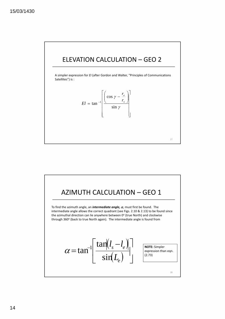
ELEVATION CALCULATION – GEO 2
A simpler expression for El (after Gordon and Walter “Principles of CommunicationsA simpler expression for El (after Gordon and Walter, Principles of Communications Satellites”) is :
⎥⎥⎥⎥⎤
⎢⎢⎢⎢⎡
⎟⎟⎠
⎞⎜⎜⎝
⎛−
= −
γ
γ
sin
costan 1 s
e
rr
El
27
⎥⎥⎦⎢
⎢⎣
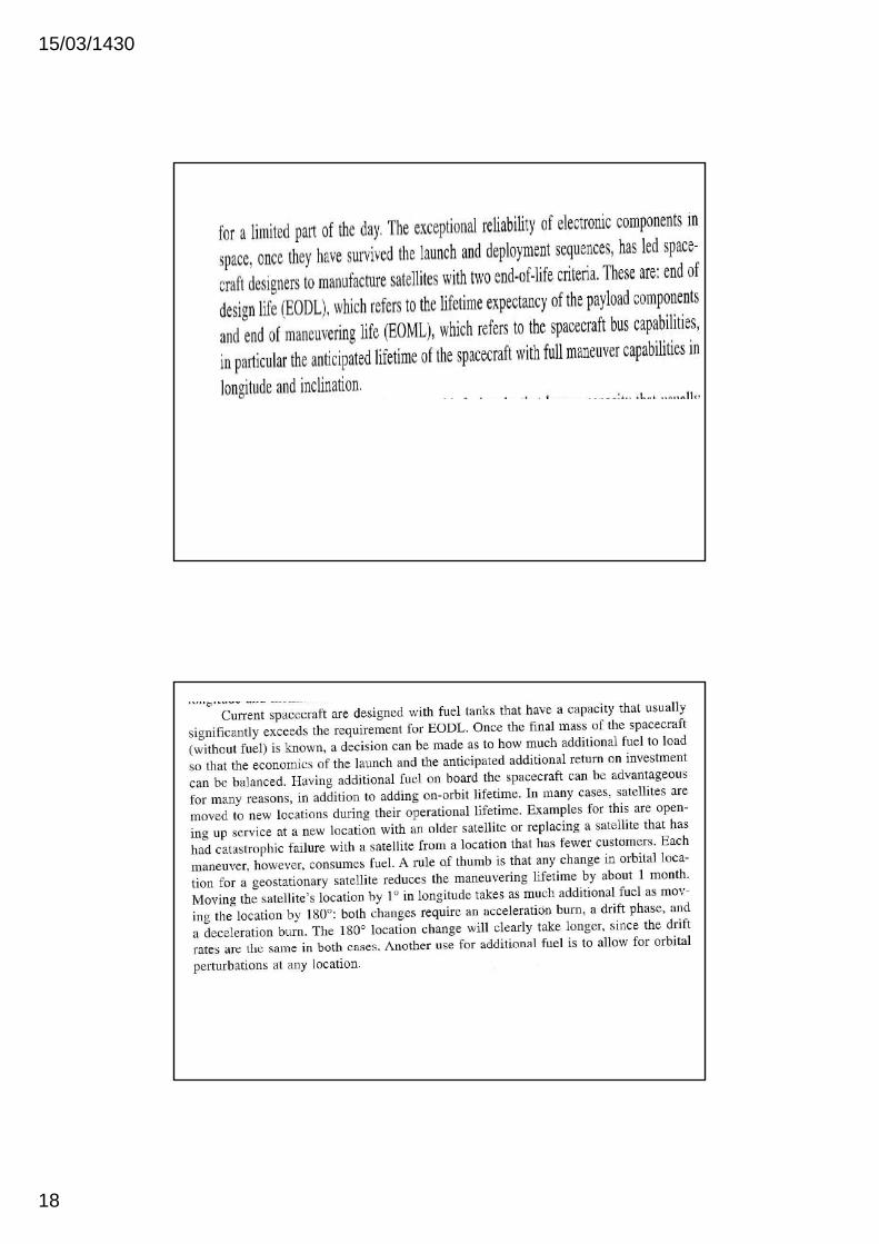
AZIMUTH CALCULATION – GEO 1
To find the azimuth angle, an intermediate angle, α, must first be found. The intermediate angle allows the correct quadrant (see Figs. 2.10 & 2.13) to be found since the azimuthal direction can lie anywhere between 0o (true North) and clockwise through 360o (back to true North again). The intermediate angle is found from
( ) ⎤⎡ lltan
28
( )( ) ⎥
⎦
⎤⎢⎣
⎡ −= −
e
es
Lll
sintan
tan 1α NOTE: Simpler expression than eqn. (2.73)

15/03/1430
15
AZIMUTH CALCULATION – GEO 2
Case 1: Earth station in the Northern Hemisphere with(a) Satellite to the SE of the earth station: Az = 180o ‐ α (b)
Satellite to the SW of the earth station: Az = 180o + αCase 2: Earth station in the Southern Hemisphere with
(c) Satellite to the NE of the earth station: Az = α (d) Satellite to the NW of the earth station: Az = 360o ‐ α
29

15/03/1430
16
VISIBILITY TEST
A simple test, called the visibility test will quickly tell you whether you can operate a satellite into a given location.
A positive (or zero) elevation angle requires (see Fig. 2.13)
( )γcose
sr
r ≥ Eqns. (2.42) &
31
( )γwhich yields
⎟⎟⎠
⎞⎜⎜⎝
⎛≤ −
s
e
rr1cosγ
(2.43)

15/03/1430
17
15/03/1430
18

15/03/1430
19
EXAMPLE OF A GEOLOOK ANGLE ALCULATION ‐ 1
FIND the Elevation and Azimuth Look Angles forFIND the Elevation and Azimuth Look Angles for the following case:
Earth Station Latitude 52o N
Earth Station Longitude 0o
Satellite Latitude 0o
Satellite Longitude 66o E
London, England Dockland region
Geostationary INTELSAT IOR
37
Primary
EXAMPLE OF A GEOLOOK ANGLE ALCULATION ‐ 1
Step 1. Find the central angle γ( ) ( ) (l l )cos(γ) = cos(Le) cos(ls‐le)
= cos(52) cos(66)= 0.2504
yielding γ = 75.4981o
Step 2. Find the elevation angle El
38
⎥⎥⎥⎥⎥
⎦
⎤
⎢⎢⎢⎢⎢
⎣
⎡⎟⎟⎠
⎞⎜⎜⎝
⎛−
= −
γ
γ
sin
costan 1 s
e
rr
El

15/03/1430
20
EXAMPLE OF A GEOLOOK ANGLE ALCULATION ‐ 1
Step 2 contd.
El = tan‐1[ (0.2504 – (6378.14 / 42164)) / sin (75.4981) ]= 5.85o
Step 3. Find the intermediate angle, α
( )⎥⎤
⎢⎡ − es lltan1
39
( )( ) ⎥
⎦⎢⎣
= −
e
es
Lsintan 1α
= tan‐1 [ (tan (66 ‐ 0)) / sin (52) ]
= 70.6668
EXAMPLE OF A GEOLOOK ANGLE ALCULATION ‐ 1
The earth station is in the Northern hemisphere and the satellite is to the South East ofThe earth station is in the Northern hemisphere and the satellite is to the South East of the earth station. This gives
Az = 180o ‐ α= 180 – 70.6668 = 109.333o (clockwise from true North)
ANSWER: The look‐angles to the satellite are
Elevation Angle = 5.85o
40
Azimuth Angle = 109.33o

15/03/1430
21
OPERATIONAL LIMITATIONS• For Geostationary Satellitesγ ≤ 81 3oγ ≤ 81.3o
• This would give an elevation angle = 0o
• Not normal to operate down to zero• usual limits are C‐Band 5o
Ku‐Band 10o
41
Ka‐ and V‐Band20o
extra

15/03/1430
22
Elevation
Azimuth and elevation refer to the satellite TV dish pointing angles.
Elevation refers to the angle between the dish pointing direction, directly towards the satellite, and the local horizontal plane. It is the up‐down angle.
When your dish is pointed almost straight up the elevation angle is nearly 90 degrees. Sites near the equator may require you to point to almost 90 deg elevation angle when the longitude of the satellite is similar to the longitude of the site location. In high elevation cases watch out for the possibility of rain water collecting in the dish. It is easy to set up the elevation angle accurately, using:
(a) a scale marked on the mount bracket. This is almost essential for 'offset antennas' with the feed at the bottom on an arm. Make sure the pole mount is vertical using a bubble level or weighted string in two positions at right angles around the pole. The offset angle may be documented in the installation instructions.
(b) using an inclinometer. These typically have a bubble level and a rotary scale marked in degrees. Think about low angles (near zero), the 45 d h lf l d hi h l (t d 90 d ) d k th t l di k Y d t dd45 deg half way angle and high angles (towards 90 deg) and make sure that your scale readings make sense. You may need to add or subtract 90 or 180 deg and even to read the scale backwards. If you are using an axi‐symmetric dish the back of the dish is normally at right angles to the beam and there may be some suitable flat part where you can apply the inclinometer.
(c) If you don't have an inclinometer then make an inclinometer using a piece of card, a length of cotton and a small weight (small metal nut, for example). Make a hole near one edge and insert the thread so that the weight dangles across the card. Draw on the card the exact elevation angle required using a school compass or two lines at right angles and trigonometry (tan function suggested) at Start,Programmes, Accessories, Calculator, Scientific mode. This kind of home made device can be far more accurate that a small inclinometer sold in a DIY store. For large dishes a long plumb line can be used and sideways measurements used with tan tables to determine angles accurately.
Azimuth refers to the rotation of the whole antenna around a vertical axis. It is the side to side angle.
Typically you loosen the main mount bracket and swing the whole dish all the way around in a 360 deg circle.By definition North is 0 deg, East is 90 deg, South is 180 deg and west is 270 deg. North can also be called 360 deg.
Note that you find a satellite by pre‐setting the elevation accurately and then swinging the whole antenna boldly in azimuth till the signal locks up ‐ so an approximate azimuth angle is normally sufficient. The dish pointing calculator gives the required azimuth angle both relative to true north and relative to magnetic compass north.
When using a magnetic compass keep away from metal structures. This is obviously a problem in many cases both with the antenna steelwork and building structures. If, for example, you have a close angle clearance problem with say an adjacent wall then you may need to walk some distance away and sight towards the satellite from say 50 yards back. Large scale precision maps / plans can be useful in accurately defining angles. Also consider long range views of say church towers that might provide an accurate azimuth reference.
If you are in the northern hemisphere then remember that the sun rises in the east, reaches its highest angle at due south and sets in the west. If you are in the southern hemisphere then remember that the sun rises in the east, reaches its highest angle at due north and sets in the west. If you are away from the equator and it is a sunny day you can approximately determine south simply by considering where the sun is and the general time of day. To calculate sun or moon angles at any time go here http://aa.usno.navy.mil/data/docs/AltAz.php Sun or moon altitude is the same thing as elevation angle. If you are near the equator note where the sun rose this morning ‐ that is approximately east.The north pole star gives a good fix if you are in the northern hemisphere and not too close to the equator. Here is how to find true north using the pole star. Some GPS receivers show a view of the sky with the sun and moon marked. Line up with one of these and you have a good bearings. Also with GPS you can walk a while in a straight line and determine the azimuth bearing angle of that line.


![Discrete-Time Signals: Time-Domain Representationuserspages.uob.edu.bh/mangoud/mohab/Courses_files/… · · 2014-10-18• Discrete-time signal represented by {x[n]} ... 2 3 4 n](https://img.pdfslide.us/doc/110x75/5aeca2ec7f8b9a3b2e8f6970/discrete-time-signals-time-domain-repr-2014-10-18-discrete-time-signal-represented.jpg)