Embed Size (px)
Citation preview
8/3/2019 lecture23-1233854096875992-3
http://slidepdf.com/reader/full/lecture23-1233854096875992-3 1/41
1
Simplified Reference Model
Application
Transport
Network
Data Link
Physical
Medium
Data Link
Physical
Application
Transport
Network
Data Link
Physical
Data Link
Physical
Network Network
Radio

8/3/2019 lecture23-1233854096875992-3
http://slidepdf.com/reader/full/lecture23-1233854096875992-3 2/41
2
Reference Model
Physical Layer :
Bit Stream to signal conversion
Frequency selection Generation of carrier frequency
Data modulation over carrier frequency
Data encryption
8/3/2019 lecture23-1233854096875992-3
http://slidepdf.com/reader/full/lecture23-1233854096875992-3 3/41
3
Reference Model
Data Link Layer :
Data Multiplexing
Error detection and correction
Medium Access
In essence :
Reliable point-to-point transfer of databetween sender and receiver.

8/3/2019 lecture23-1233854096875992-3
http://slidepdf.com/reader/full/lecture23-1233854096875992-3 4/41
4
Reference Model
Network Layer :
Connection setup
Packet routing Handover between networks
Routing
Target device location Quality of service (QoS)
8/3/2019 lecture23-1233854096875992-3
http://slidepdf.com/reader/full/lecture23-1233854096875992-3 5/41
5
Reference Model
Transport Layer :
Establish End-to-End Connection
Flow control Congestion control
TCP and UDP
Applications – Browser etc.
8/3/2019 lecture23-1233854096875992-3
http://slidepdf.com/reader/full/lecture23-1233854096875992-3 6/41
6
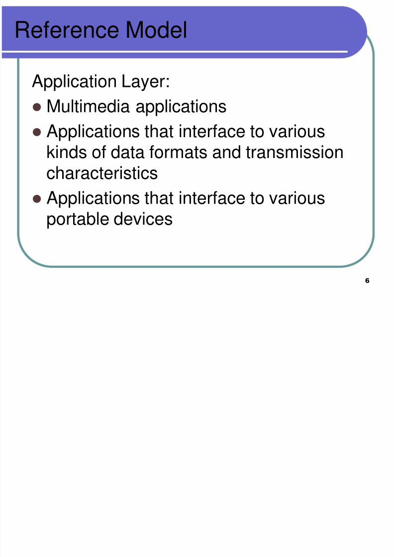
Reference Model
Application Layer:
Multimedia applications
Applications that interface to variouskinds of data formats and transmissioncharacteristics
Applications that interface to variousportable devices
8/3/2019 lecture23-1233854096875992-3
http://slidepdf.com/reader/full/lecture23-1233854096875992-3 7/41
7
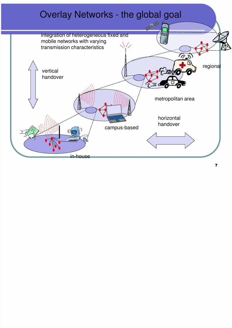
Overlay Networks - the global goal
regional
metropolitan area
campus-based
in-house
verticalhandover
horizontalhandover
integration of heterogeneous fixed and
mobile networks with varyingtransmission characteristics

8/3/2019 lecture23-1233854096875992-3
http://slidepdf.com/reader/full/lecture23-1233854096875992-3 8/41
8
Frequency Ranges
WIRELESS TRANSMISSION
1 Mm300 Hz
10 km30 kHz
100 m3 MHz
1 m300 MHz
10 mm30 GHz
100 m3 THz
1 m300 THz
visible lightVLF LF MF HF VHF UHF SHF EHF infrared UV
optical transmissioncoax cabletwistedpair
VLF = Very Low Frequency UHF = Ultra High FequencyLF = Low Frequency SHF = Super High Frequency
MF = Medium Frequency EHF = Extra High Frequency
HF = High Frequency UV = Ultraviolet Light
VHF = Very High Frequency

8/3/2019 lecture23-1233854096875992-3
http://slidepdf.com/reader/full/lecture23-1233854096875992-3 9/41
9
Frequencies
kHz Range (Low and Very Lowfrequencies)
Used for short distances using twisted copper wires
Several KHz to MHZ (Medium and HighFrequencies)
For transmission of hundreds of radio stations in the
AM and FM mode Use co-axial cables
Transmission power is several kW.
8/3/2019 lecture23-1233854096875992-3
http://slidepdf.com/reader/full/lecture23-1233854096875992-3 10/41
10
Frequencies
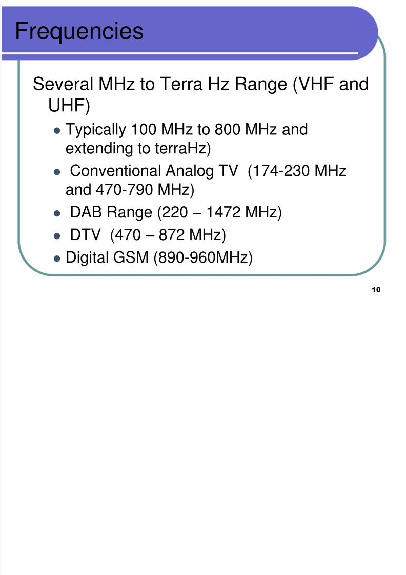
Several MHz to Terra Hz Range (VHF andUHF)
Typically 100 MHz to 800 MHz and
extending to terraHz)
Conventional Analog TV (174-230 MHzand 470-790 MHz)
DAB Range (220 – 1472 MHz) DTV (470 – 872 MHz)
Digital GSM (890-960MHz)
8/3/2019 lecture23-1233854096875992-3
http://slidepdf.com/reader/full/lecture23-1233854096875992-3 11/41
11
Frequencies
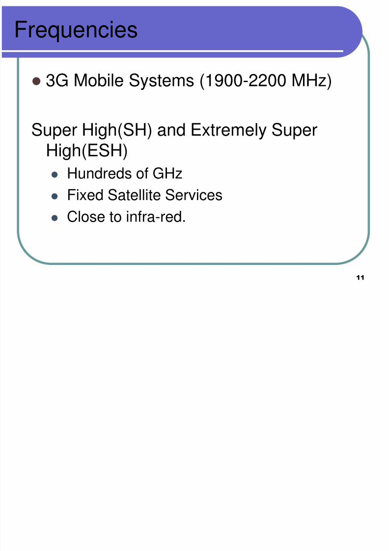
3G Mobile Systems (1900-2200 MHz)
Super High(SH) and Extremely SuperHigh(ESH)
Hundreds of GHz
Fixed Satellite Services
Close to infra-red.

8/3/2019 lecture23-1233854096875992-3
http://slidepdf.com/reader/full/lecture23-1233854096875992-3 12/41
12
Frequencies
For Several TerraHz : Optical Transmission
Why do we need very high transmissionfrequencies?
The information content in video, satellitedata etc is enormous.
If we need to accommodate many signalssimultaneously, we need a high bit ratewhich in turn demands high frequency.

8/3/2019 lecture23-1233854096875992-3
http://slidepdf.com/reader/full/lecture23-1233854096875992-3 13/41
13
REGULATIONS
International Telecommunications Union(ITU), Geneva responsible for world-widecoordination of telecommunications
activity.
ITU – R (Radio Communications sector)handles standardization in Wireless
sector.

8/3/2019 lecture23-1233854096875992-3
http://slidepdf.com/reader/full/lecture23-1233854096875992-3 14/41
14
REGULATIONS
ITU-R
Region-1
Europe, Middle East,
Former Russia, Africa
Region-2
Greenland, N & S
America
Region-3
Australia, New
Zealand

8/3/2019 lecture23-1233854096875992-3
http://slidepdf.com/reader/full/lecture23-1233854096875992-3 15/41
15
Frequency AllocationEurope USA Japan
CellularPhones
GSM 450-457, 479-486/460-467,489-496, 890-915/935-960,1710-1785/1805-1880UMTS (FDD) 1920-1980, 2110-2190UMTS (TDD) 1900-1920, 2020-2025
AMPS, TDMA, CDMA 824-849,869-894TDMA, CDMA, GSM 1850-1910,1930-1990
PDC 810-826,940-956,1429-1465,1477-1513
CordlessPhones
CT1+ 885-887, 930-932CT2864-868DECT
1880-1900
PACS 1850-1910, 1930-1990PACS-UB 1910-1930
PHS 1895-1918JCT 254-380
WirelessLANs
IEEE 802.112400-2483HIPERLAN 25150-5350, 5470-5725
902-928IEEE 802.112400-24835150-5350, 5725-5825
IEEE 802.11 2471-24975150-5250
Others RF-Control27, 128, 418, 433,
868
RF-Control315, 915
RF-Control 426, 868

8/3/2019 lecture23-1233854096875992-3
http://slidepdf.com/reader/full/lecture23-1233854096875992-3 16/41
16
REGULATIONS
PDC : Personal Digital Cellular
NMT : Nordic Mobile Telephone
DECT : Digital Enhanced CordlessTelephone
PACS : Personal Access CommunicationsSystem
8/3/2019 lecture23-1233854096875992-3
http://slidepdf.com/reader/full/lecture23-1233854096875992-3 17/41
17
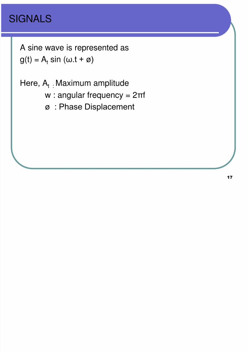
SIGNALS
A sine wave is represented as
g(t) = At sin (ω.t + ø)
Here, At : Maximum amplitudew : angular frequency = 2πf
ø : Phase Displacement
8/3/2019 lecture23-1233854096875992-3
http://slidepdf.com/reader/full/lecture23-1233854096875992-3 18/41
18
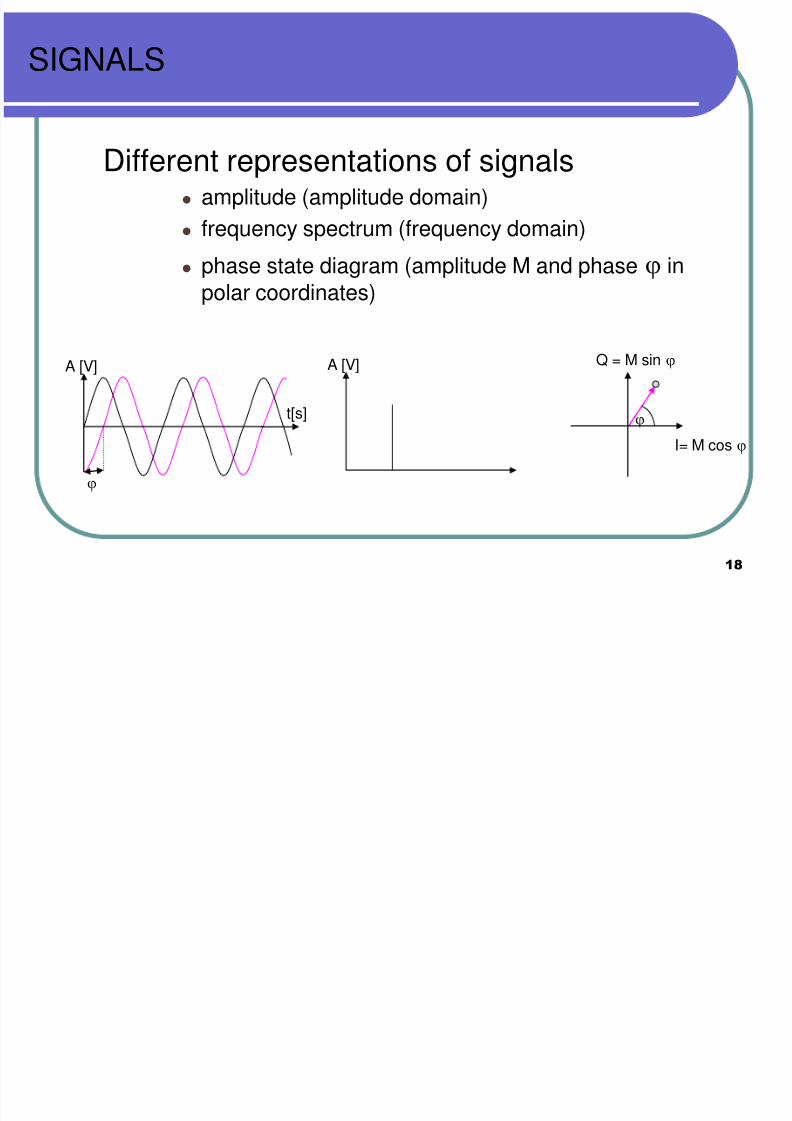
SIGNALS
Different representations of signals amplitude (amplitude domain)
frequency spectrum (frequency domain)
phase state diagram (amplitude M and phase
in
polar coordinates)
A [V]
I= M cos
Q = M sin
A [V]
t[s]
8/3/2019 lecture23-1233854096875992-3
http://slidepdf.com/reader/full/lecture23-1233854096875992-3 19/41
19
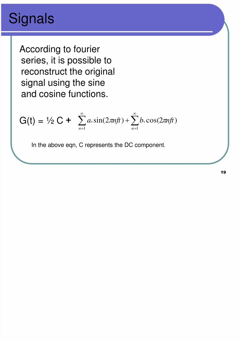
Signals
According to fourierseries, it is possible toreconstruct the original
signal using the sineand cosine functions.
G(t) = ½ C + )2cos()2sin(11
nft bnft ann
nn
In the above eqn, C represents the DC component.
8/3/2019 lecture23-1233854096875992-3
http://slidepdf.com/reader/full/lecture23-1233854096875992-3 20/41
20
Signals
As n varies, increasing number ofharmonics are added to the signalrepresentation.
As n approaches infinity, the originalsignal is truly represented.
The given signal has to be modulatedover a career frequency.

8/3/2019 lecture23-1233854096875992-3
http://slidepdf.com/reader/full/lecture23-1233854096875992-3 21/41
21
Antenas
An Antenna aids in transforming a wiredmedium to a wireless medium
Antennas couple electromagnetic energyto the space and from the space TO andFROM a wire/coaxial cable.
8/3/2019 lecture23-1233854096875992-3
http://slidepdf.com/reader/full/lecture23-1233854096875992-3 22/41
22
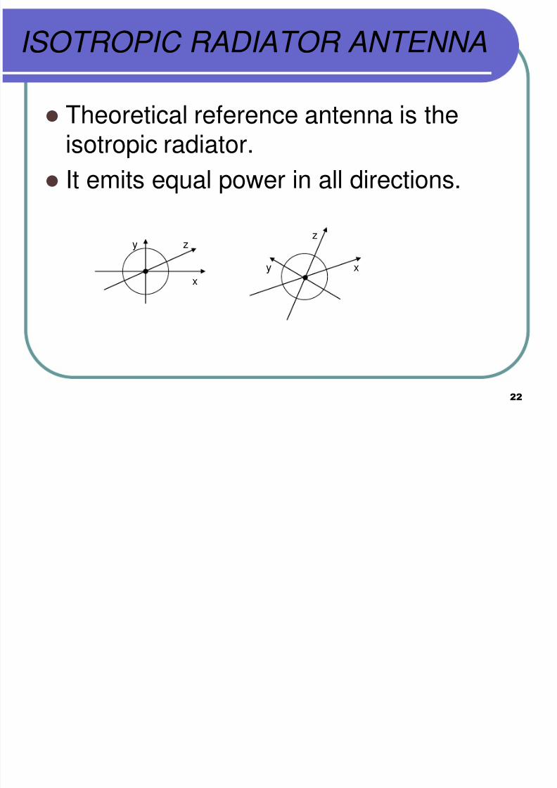
ISOTROPIC RADIATOR ANTENNA
Theoretical reference antenna is theisotropic radiator.
It emits equal power in all directions.
zy
x
z
y x

8/3/2019 lecture23-1233854096875992-3
http://slidepdf.com/reader/full/lecture23-1233854096875992-3 23/41
23
Antennas
Practical Antennas Exhibit Directional properties.
Thin Centre-fed Dipole:
λ /2
• Dipole consists of two collinear conductors separated by a small feedinggap.
• Generally, the length of the Dipole is half the wavelength of the signal tobe transmitted/received.(λ = C/f where is is the speed of light {3*10 8 m/s)

8/3/2019 lecture23-1233854096875992-3
http://slidepdf.com/reader/full/lecture23-1233854096875992-3 24/41
24
Wavelength
Forms of electromagnetic radiation like radio waves, lightwaves or infrared (heat) waves make characteristicpatterns as they travel through space. Each wave has acertain shape and length. The distance between peaks
(high points) is called wavelength.

8/3/2019 lecture23-1233854096875992-3
http://slidepdf.com/reader/full/lecture23-1233854096875992-3 25/41
25
Dipole Antenna
•When the signal is obstructed by mountains, buildings etc, the powerof the sinal gets weak.
• It can be boosted by additional devices.
8/3/2019 lecture23-1233854096875992-3
http://slidepdf.com/reader/full/lecture23-1233854096875992-3 26/41
26
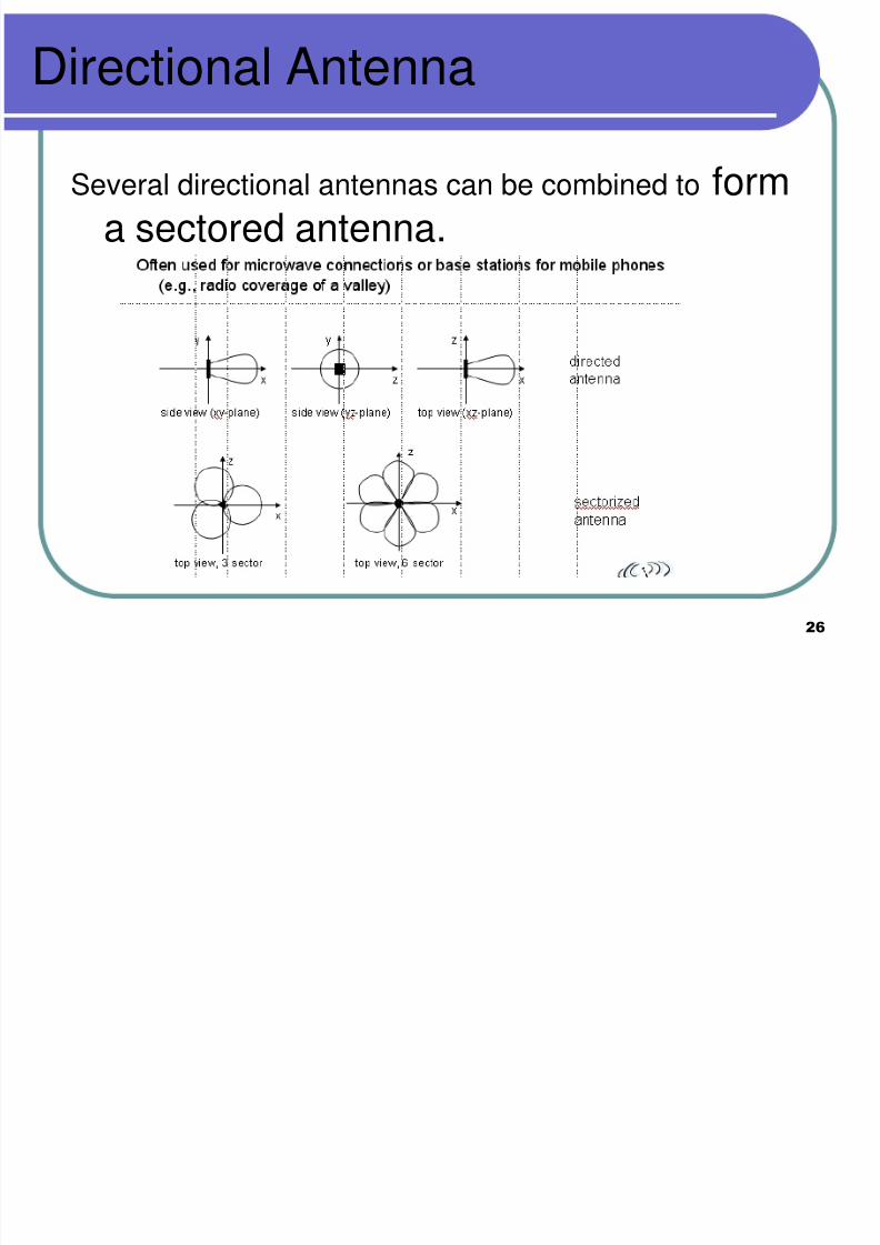
Directional Antenna
Several directional antennas can be combined to forma sectored antenna.

8/3/2019 lecture23-1233854096875992-3
http://slidepdf.com/reader/full/lecture23-1233854096875992-3 27/41
27
Signal Propagation Range
distance
sender
transmission
detection
interference
Transmission range communication possible
low error rate
Detection range
detection of the signal
possible
no communicationpossible
Interference range
signal may not bedetected
signal adds to thebackground noise
8/3/2019 lecture23-1233854096875992-3
http://slidepdf.com/reader/full/lecture23-1233854096875992-3 28/41
28
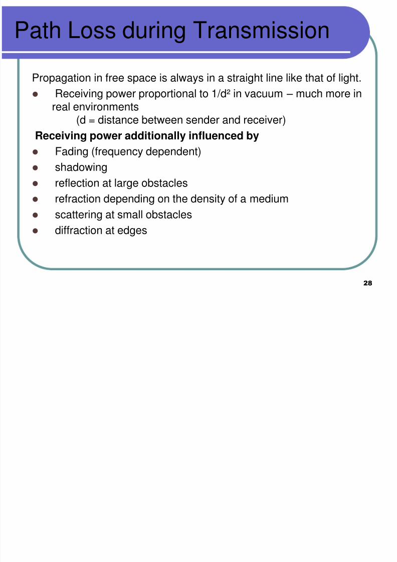
Path Loss during Transmission
Propagation in free space is always in a straight line like that of light.
Receiving power proportional to 1/d² in vacuum – much more inreal environments
(d = distance between sender and receiver)
Receiving power additionally influenced by Fading (frequency dependent)
shadowing
reflection at large obstacles
refraction depending on the density of a medium
scattering at small obstacles
diffraction at edges
8/3/2019 lecture23-1233854096875992-3
http://slidepdf.com/reader/full/lecture23-1233854096875992-3 29/41
29
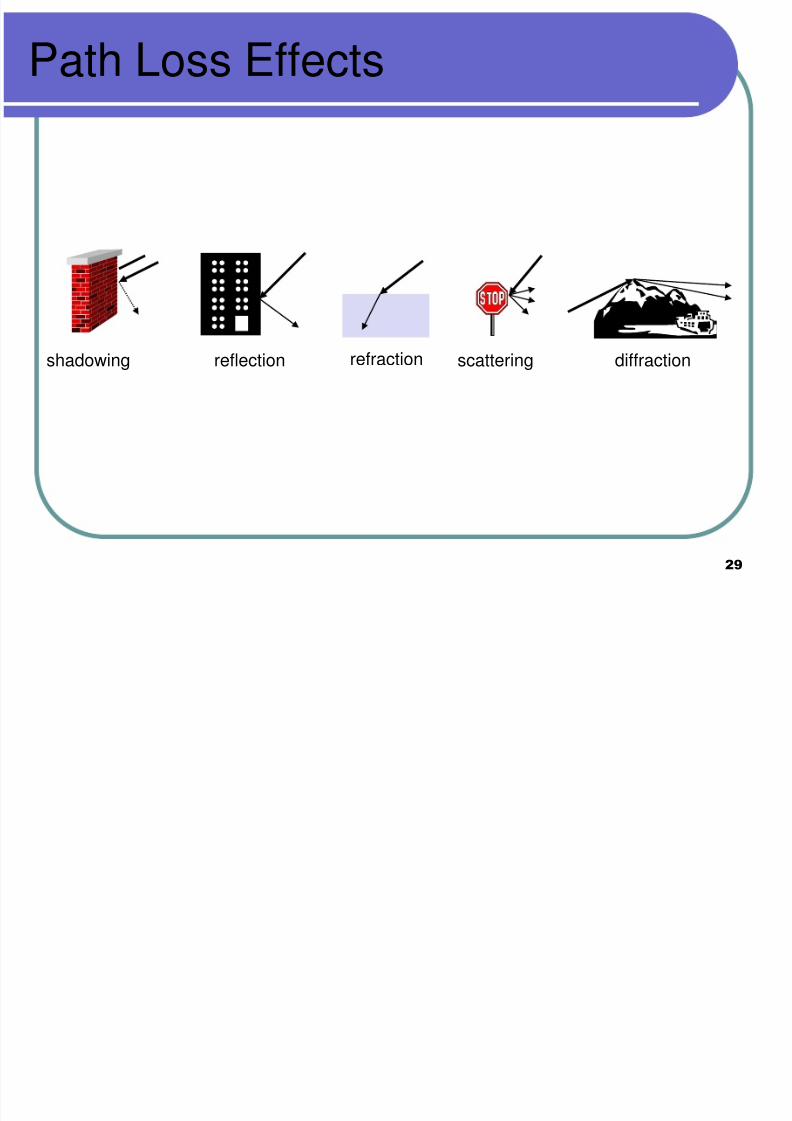
Path Loss Effects
reflection scattering diffractionshadowing refraction
8/3/2019 lecture23-1233854096875992-3
http://slidepdf.com/reader/full/lecture23-1233854096875992-3 30/41
30
Signal Propagation effects
Signal Penetration through objects :
At lower frequency, the penetration is higher.
At very high frequencies, the transmission
behavior of the wave is close to that of light,

8/3/2019 lecture23-1233854096875992-3
http://slidepdf.com/reader/full/lecture23-1233854096875992-3 31/41
31
Propagation behavior of waves
Ground Wave (<2 MHz): Can follow earth’s
surface and can propagate long distances
[Submarine communication, AM Radio etc]
Sky Wave (2-30 MHz) : Waves are reflected.They can bounce back and forth betweenionosphere and earth’s surface and can travel
around the world.
Line of Sight [>30 MHz) : The waves are bent
by refraction.
8/3/2019 lecture23-1233854096875992-3
http://slidepdf.com/reader/full/lecture23-1233854096875992-3 32/41
32
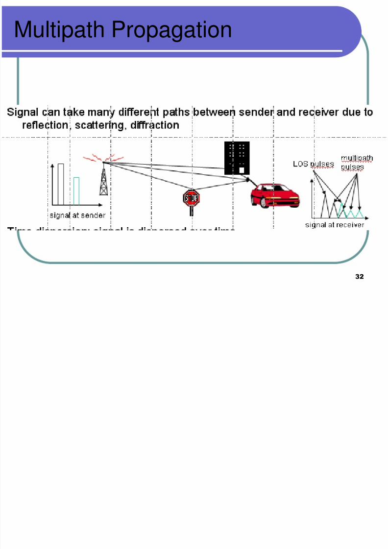
Multipath Propagation
8/3/2019 lecture23-1233854096875992-3
http://slidepdf.com/reader/full/lecture23-1233854096875992-3 33/41
33

8/3/2019 lecture23-1233854096875992-3
http://slidepdf.com/reader/full/lecture23-1233854096875992-3 34/41
34
Multipath Propagation
Radio waves sent from the sender to thereceiver can travel in a straight line aswell as may reach the destination after
being reflected by several obstacles.
The signal arrives at different times atthe receiver. THIS EFFECT IS CALLED
DELAY SPREAD

8/3/2019 lecture23-1233854096875992-3
http://slidepdf.com/reader/full/lecture23-1233854096875992-3 35/41
35
Multipath Propagation
The original signal gets a spread signal
The order of delays is 2 to 12 microsecs.
8/3/2019 lecture23-1233854096875992-3
http://slidepdf.com/reader/full/lecture23-1233854096875992-3 36/41
36
Effects of delay spread
Short-pulse signals will be spread into abroader impulse or several weakerpulses.
In the fig, the impulse at the sender isreceived as three smaller pulses at thereceiver.
Also, the power level of the receivedpulses will be low. So, they will beperceived as noise.
8/3/2019 lecture23-1233854096875992-3
http://slidepdf.com/reader/full/lecture23-1233854096875992-3 37/41
37
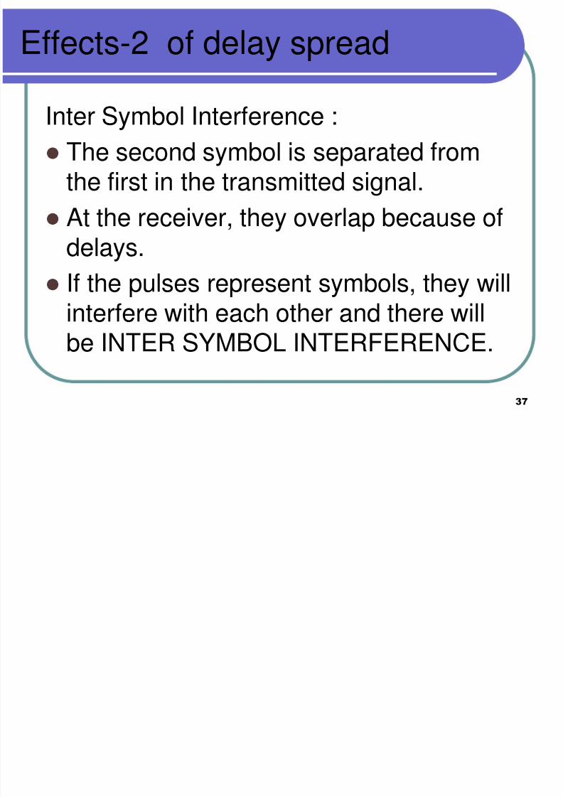
Effects-2 of delay spread
Inter Symbol Interference :
The second symbol is separated fromthe first in the transmitted signal.
At the receiver, they overlap because ofdelays.
If the pulses represent symbols, they willinterfere with each other and there willbe INTER SYMBOL INTERFERENCE.

8/3/2019 lecture23-1233854096875992-3
http://slidepdf.com/reader/full/lecture23-1233854096875992-3 38/41
38
One possible solution
Receiver should know the delaycharacteristics of different paths.
Receiver can compensate for thedistortion
Receiver can equalize the signals basedon the channel characteristics.

8/3/2019 lecture23-1233854096875992-3
http://slidepdf.com/reader/full/lecture23-1233854096875992-3 39/41
39
Effects of mobility
Channel characteristics change over timeand location
signal paths change
different delay variations of different signalparts
different phases of signal parts
quick changes in the power received(short term fading) short term fading
long termfading
t
power
8/3/2019 lecture23-1233854096875992-3
http://slidepdf.com/reader/full/lecture23-1233854096875992-3 40/41
40
Solution for Long Term Fading
Senders can increase/decrease poweron a regular basis so that the receivedpower is within certain bounds.
8/3/2019 lecture23-1233854096875992-3
http://slidepdf.com/reader/full/lecture23-1233854096875992-3 41/41
Long Term Fading
Additional changes in
distance to sender
obstacles further away
slow changes in the average powerreceived (long term fading)