Embed Size (px)
Citation preview
© 2014 Pearson Education, Inc.
This work is protected by United States copyright laws and is provided solely for the use of instructors in teaching their courses and assessing student learning. Dissemination or sale of any part of this work (including on the World Wide Web) will destroy the integrity of the work and is not permitted. The work and materials from it should never be made available to students except by instructors using the accompanying text in their classes. All recipients of this work are expected to abide by these restrictions and to honor the intended pedagogical purposes and the needs of other instructors who rely on these materials.
Lecture PowerPoints
Chapter 23 Physics: Principles with Applications, 7th edition
Giancoli
Chapter 23 Light: Geometric Optics
© 2014 Pearson Education, Inc.
Contents of Chapter 23
• The Ray Model of Light
• Reflection; Image Formed by a Plane Mirror
• Formation of Images by Spherical Mirrors
• Index of Refraction
• Refraction: Snell’s Law
© 2014 Pearson Education, Inc.
Contents of Chapter 23
• Total Internal Reflection; Fiber Optics
• Thin Lenses; Ray Tracing
• The Thin Lens Equation
• Combinations of Lenses
• Lensmaker’s Equation
© 2014 Pearson Education, Inc.
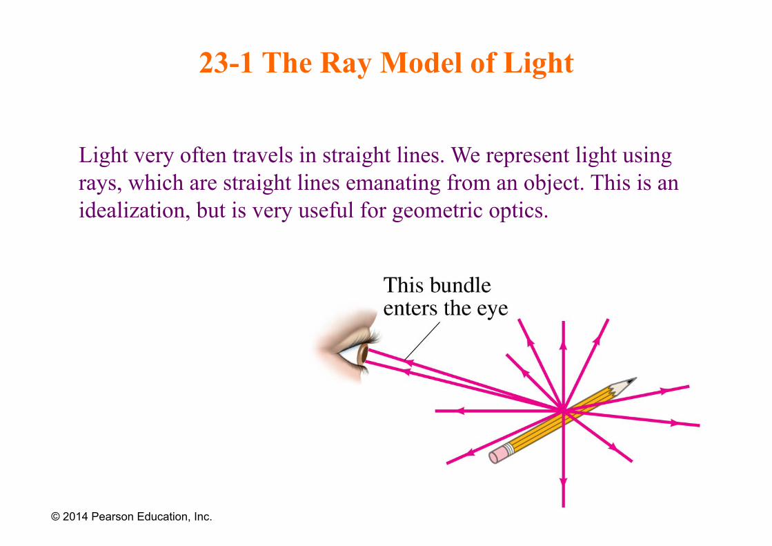
23-1 The Ray Model of Light
Light very often travels in straight lines. We represent light using rays, which are straight lines emanating from an object. This is an idealization, but is very useful for geometric optics.
© 2014 Pearson Education, Inc.
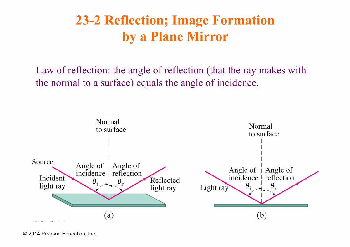
23-2 Reflection; Image Formation by a Plane Mirror
Law of reflection: the angle of reflection (that the ray makes with the normal to a surface) equals the angle of incidence.
© 2014 Pearson Education, Inc.
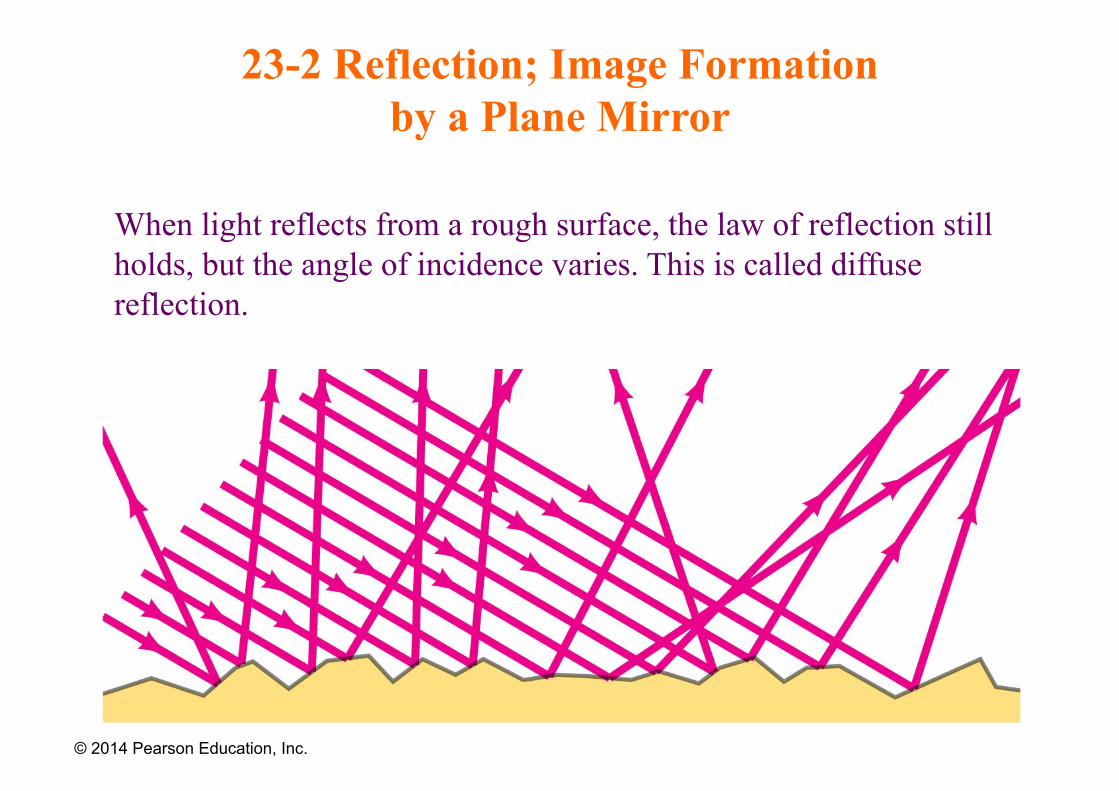
23-2 Reflection; Image Formation by a Plane Mirror
When light reflects from a rough surface, the law of reflection still holds, but the angle of incidence varies. This is called diffuse reflection.
© 2014 Pearson Education, Inc.
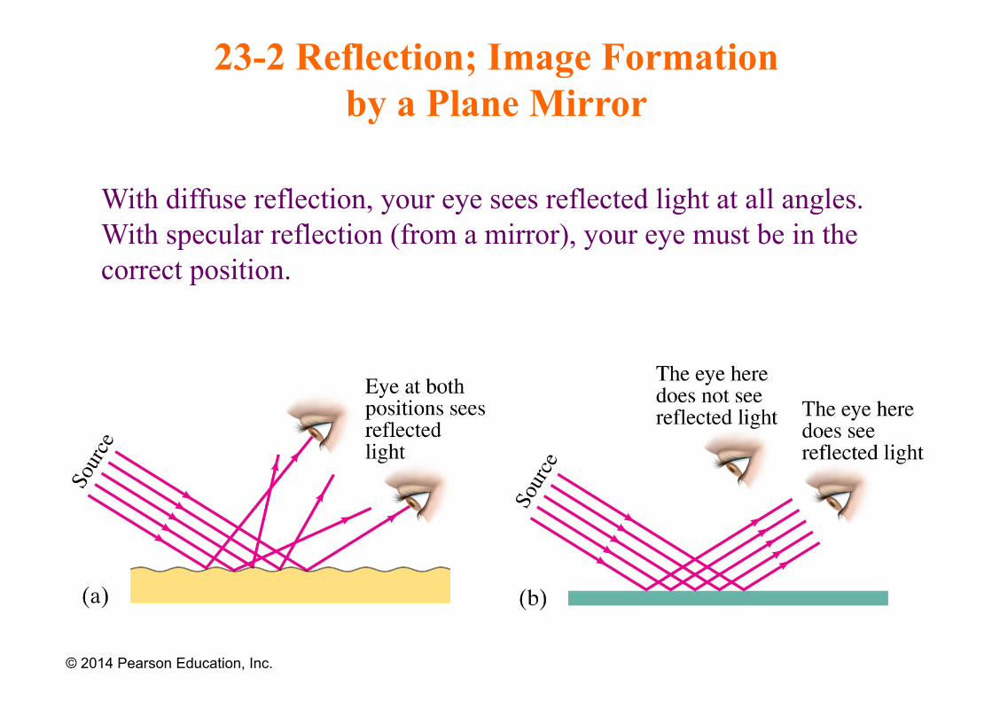
23-2 Reflection; Image Formation by a Plane Mirror
With diffuse reflection, your eye sees reflected light at all angles. With specular reflection (from a mirror), your eye must be in the correct position.
© 2014 Pearson Education, Inc.
23-2 Reflection; Image Formation by a Plane Mirror
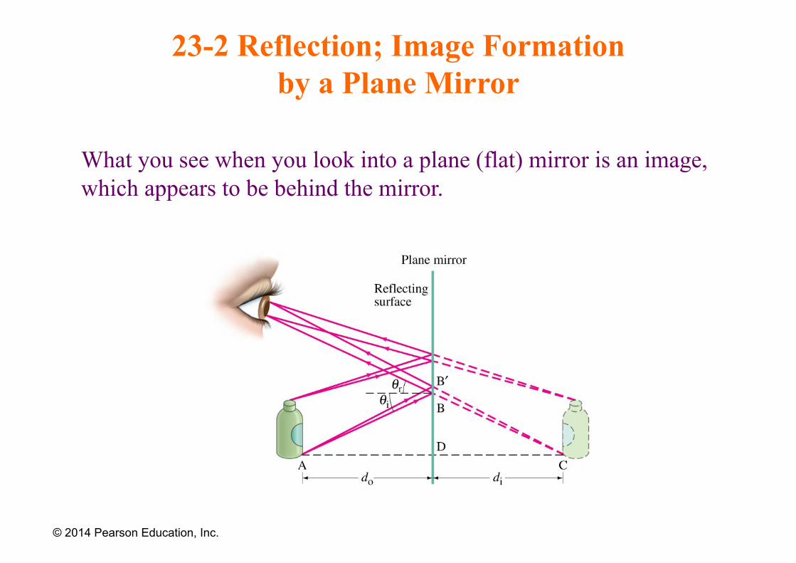
What you see when you look into a plane (flat) mirror is an image, which appears to be behind the mirror.
© 2014 Pearson Education, Inc.
23-2 Reflection; Image Formation by a Plane Mirror
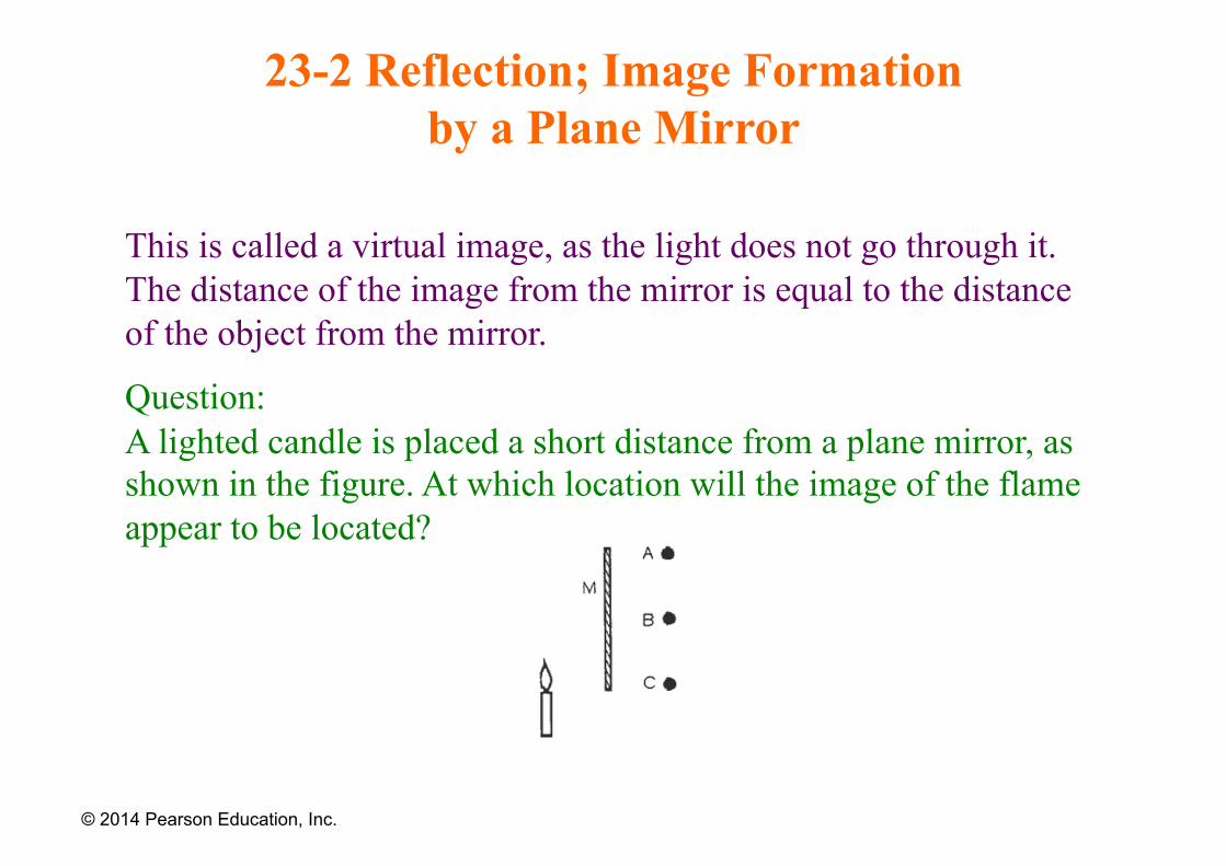
This is called a virtual image, as the light does not go through it. The distance of the image from the mirror is equal to the distance of the object from the mirror.
Question: A lighted candle is placed a short distance from a plane mirror, as shown in the figure. At which location will the image of the flame appear to be located?
© 2014 Pearson Education, Inc.
Examples
Two plane mirrors make an angle of 30° with each other. A light ray enters the system and is reflected once off of each mirror. Through what angle is the ray turned?
• Answer: 60°
• A person jogs toward a plane mirror at a speed of 3 m/s. How fast is he approaching his image in the mirror?
• Answer: 6 m/s
© 2014 Pearson Education, Inc.
23-3 Formation of Images by Spherical Mirrors
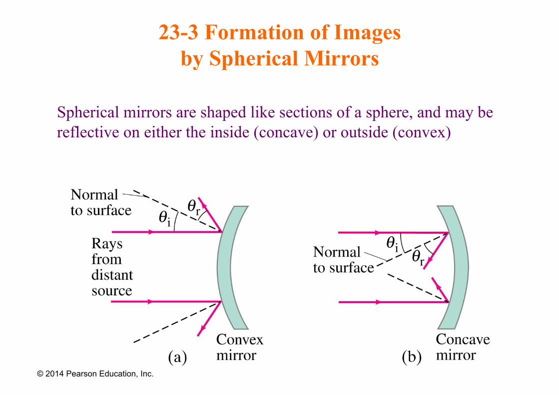
Spherical mirrors are shaped like sections of a sphere, and may be reflective on either the inside (concave) or outside (convex)
© 2014 Pearson Education, Inc.
23-3 Formation of Images by Spherical Mirrors
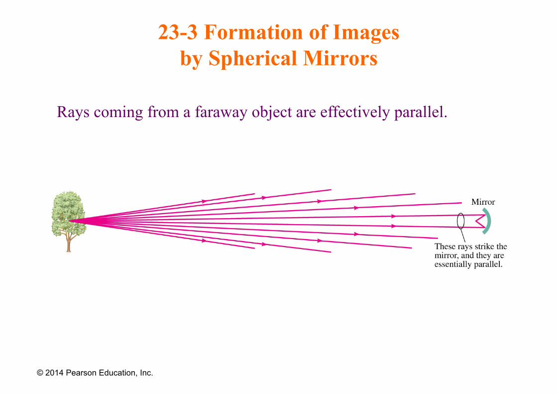
Rays coming from a faraway object are effectively parallel.
© 2014 Pearson Education, Inc.
23-3 Formation of Images by Spherical Mirrors
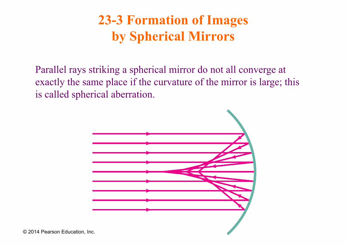
Parallel rays striking a spherical mirror do not all converge at exactly the same place if the curvature of the mirror is large; this is called spherical aberration.
© 2014 Pearson Education, Inc.
23-3 Formation of Images by Spherical Mirrors
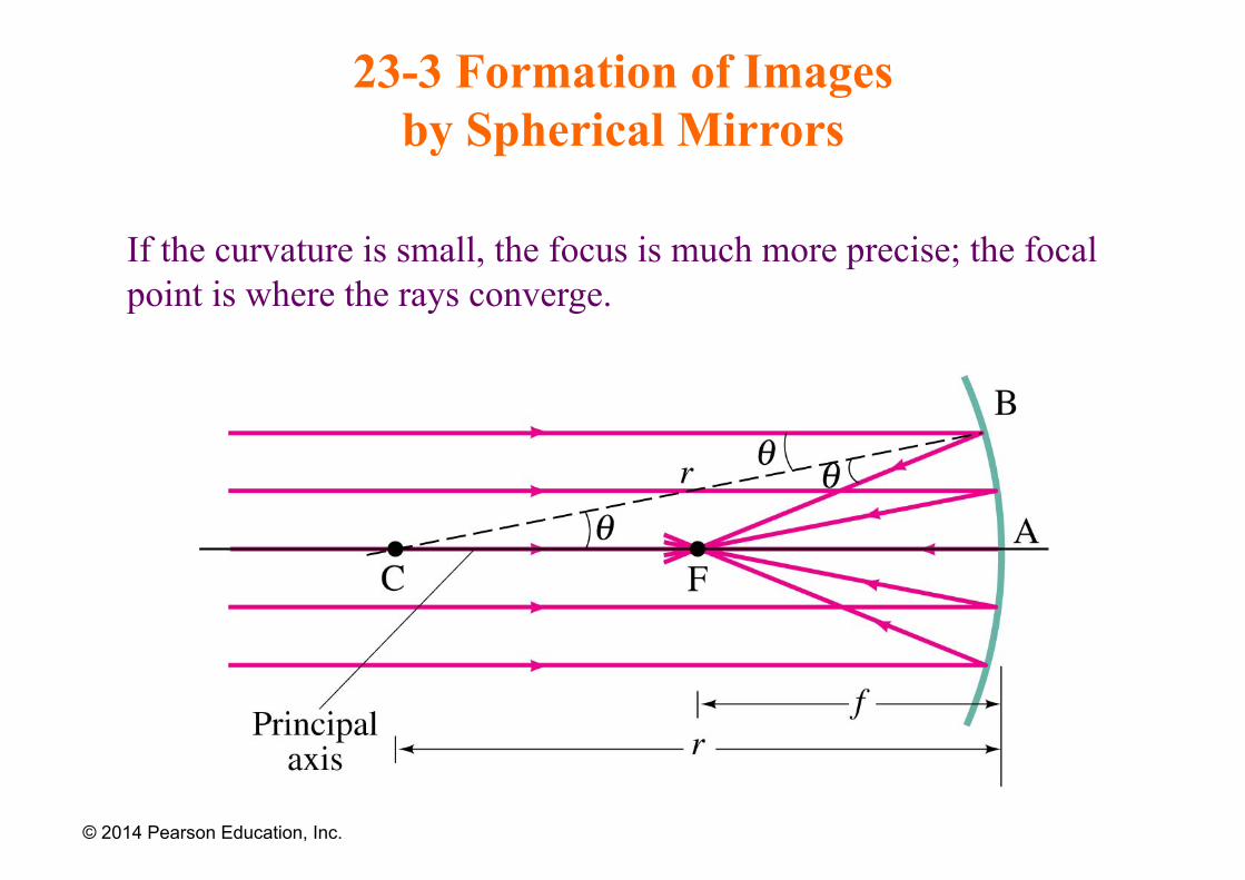
If the curvature is small, the focus is much more precise; the focal point is where the rays converge.
© 2014 Pearson Education, Inc.
23-3 Formation of Images by Spherical Mirrors
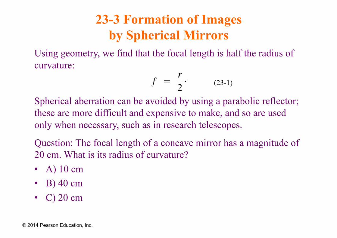
Using geometry, we find that the focal length is half the radius of curvature:
Spherical aberration can be avoided by using a parabolic reflector; these are more difficult and expensive to make, and so are used only when necessary, such as in research telescopes.
Question: The focal length of a concave mirror has a magnitude of 20 cm. What is its radius of curvature? • A) 10 cm • B) 40 cm • C) 20 cm
© 2014 Pearson Education, Inc.
(23-1)
23-3 Formation of Images by Spherical Mirrors
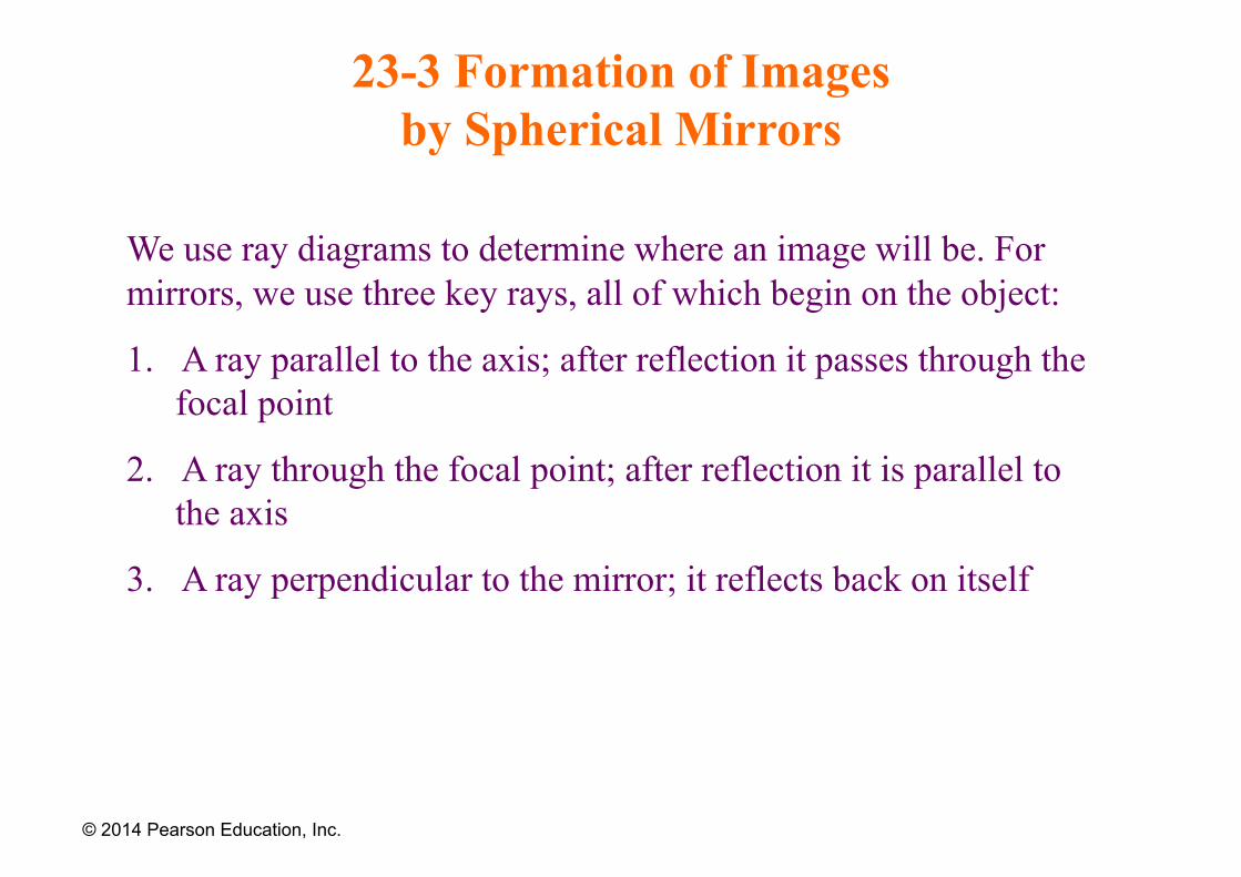
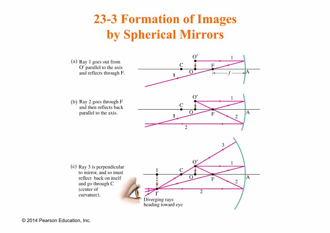
We use ray diagrams to determine where an image will be. For mirrors, we use three key rays, all of which begin on the object:
1. A ray parallel to the axis; after reflection it passes through the focal point
2. A ray through the focal point; after reflection it is parallel to the axis
3. A ray perpendicular to the mirror; it reflects back on itself
© 2014 Pearson Education, Inc.
23-3 Formation of Images by Spherical Mirrors
© 2014 Pearson Education, Inc.
23-3 Formation of Images by Spherical Mirrors
The intersection of these three rays gives the position of the image of that point on the object. To get a full image, we can do the same with other points (two points suffice for many purposes).
© 2014 Pearson Education, Inc.
23-3 Formation of Images by Spherical Mirrors
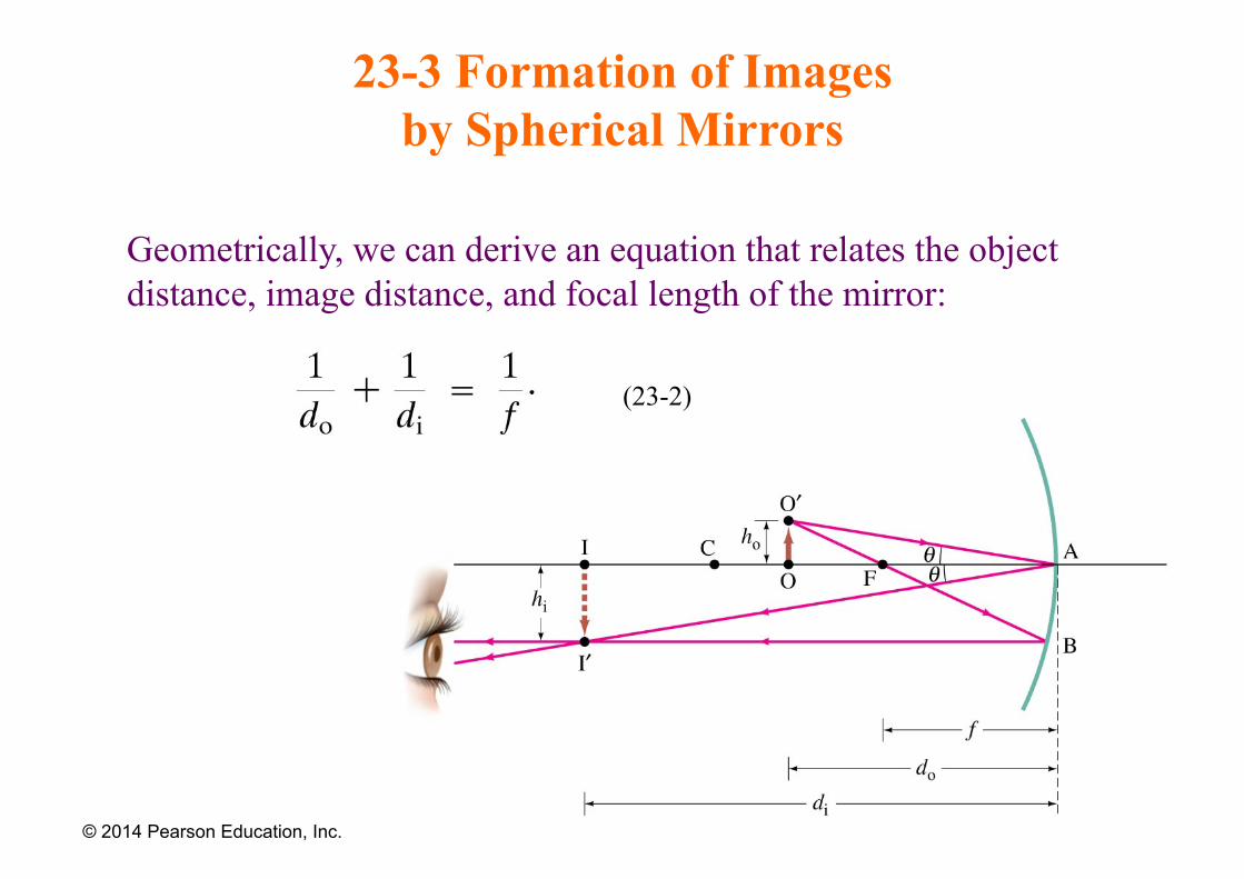
Geometrically, we can derive an equation that relates the object distance, image distance, and focal length of the mirror:
© 2014 Pearson Education, Inc.
(23-2)
23-3 Formation of Images by Spherical Mirrors
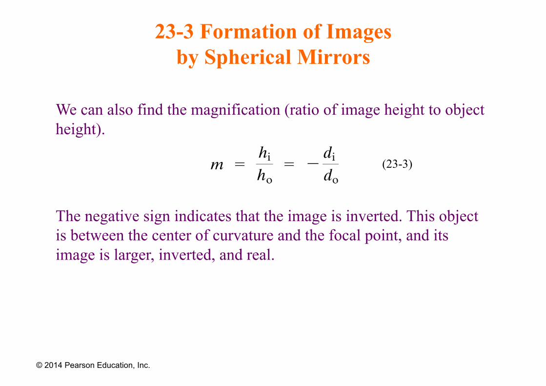
We can also find the magnification (ratio of image height to object height).
The negative sign indicates that the image is inverted. This object is between the center of curvature and the focal point, and its image is larger, inverted, and real.
© 2014 Pearson Education, Inc.
(23-3)
23-3 Formation of Images by Spherical Mirrors
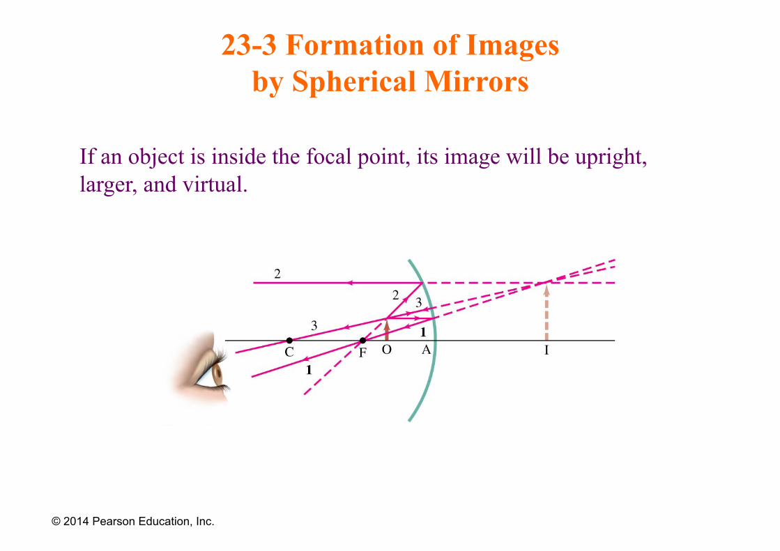
If an object is inside the focal point, its image will be upright, larger, and virtual.
© 2014 Pearson Education, Inc.
23-3 Formation of Images by Spherical Mirrors
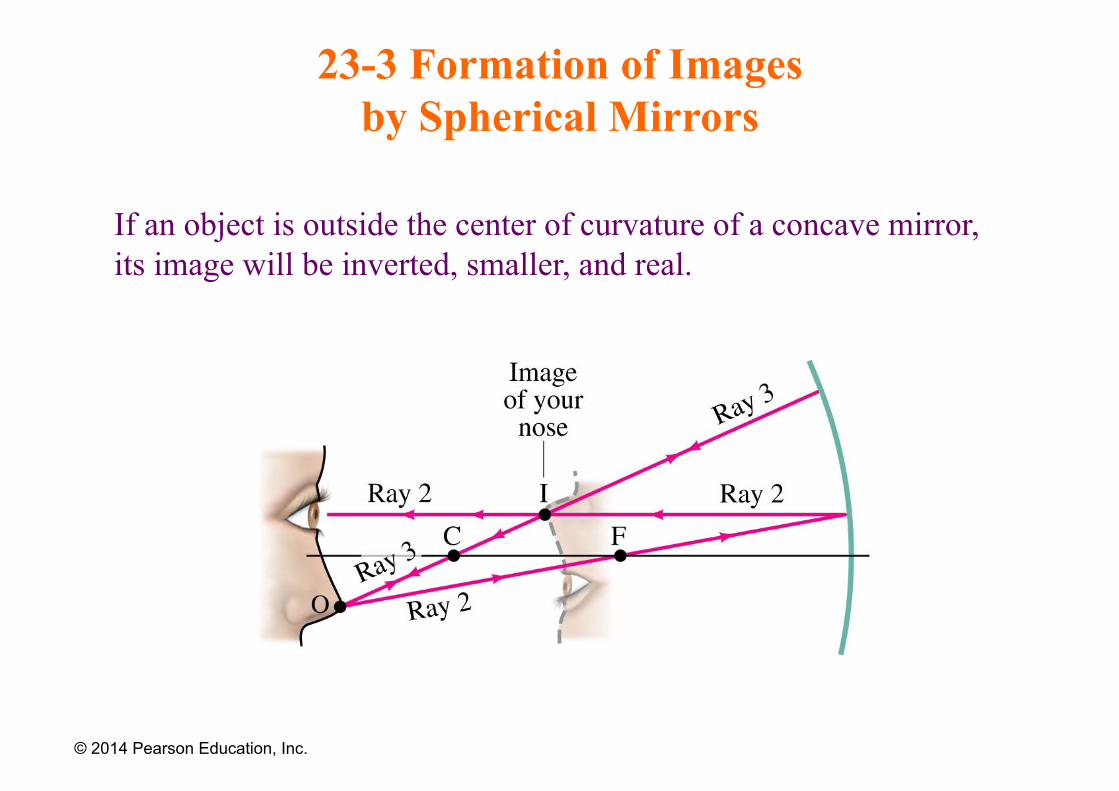
If an object is outside the center of curvature of a concave mirror, its image will be inverted, smaller, and real.
© 2014 Pearson Education, Inc.
23-3 Formation of Images by Spherical Mirrors
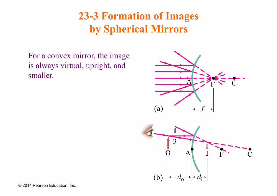
For a convex mirror, the image is always virtual, upright, and smaller.
© 2014 Pearson Education, Inc.
23-3 Formation of Images by Spherical Mirrors
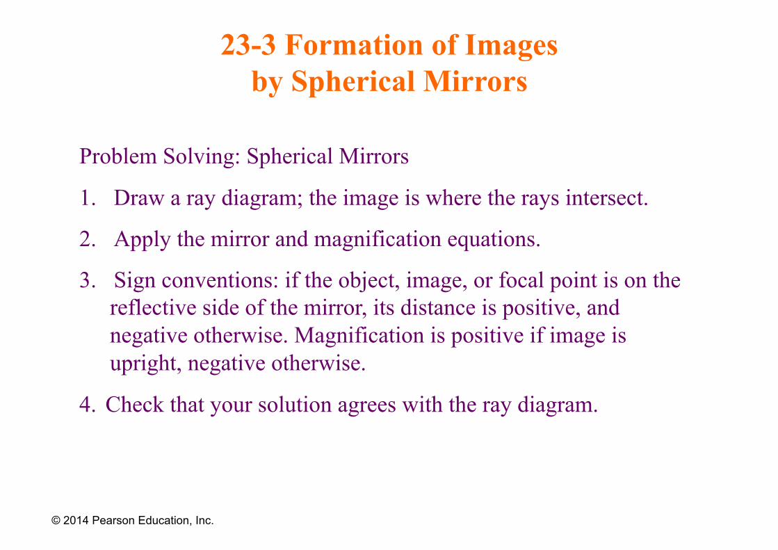
Problem Solving: Spherical Mirrors
1. Draw a ray diagram; the image is where the rays intersect.
2. Apply the mirror and magnification equations.
3. Sign conventions: if the object, image, or focal point is on the reflective side of the mirror, its distance is positive, and negative otherwise. Magnification is positive if image is upright, negative otherwise.
4. Check that your solution agrees with the ray diagram.
© 2014 Pearson Education, Inc.
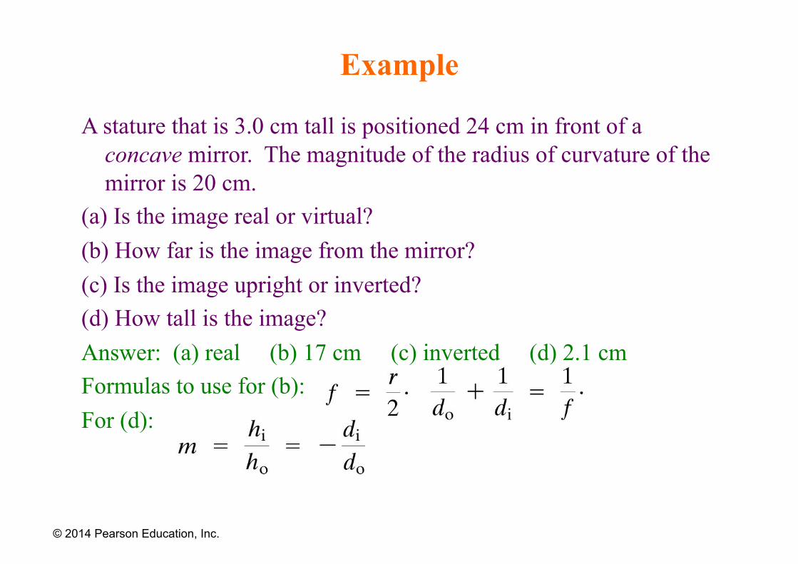
Example
A stature that is 3.0 cm tall is positioned 24 cm in front of a concave mirror. The magnitude of the radius of curvature of the mirror is 20 cm.
(a) Is the image real or virtual? (b) How far is the image from the mirror? (c) Is the image upright or inverted? (d) How tall is the image? Answer: (a) real (b) 17 cm (c) inverted (d) 2.1 cm Formulas to use for (b): For (d):
© 2014 Pearson Education, Inc.
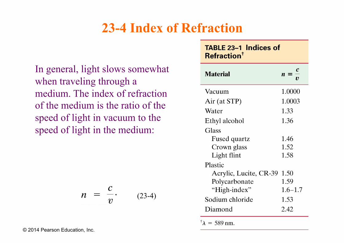
23-4 Index of Refraction
In general, light slows somewhat when traveling through a medium. The index of refraction of the medium is the ratio of the speed of light in vacuum to the speed of light in the medium:
© 2014 Pearson Education, Inc.
(23-4)
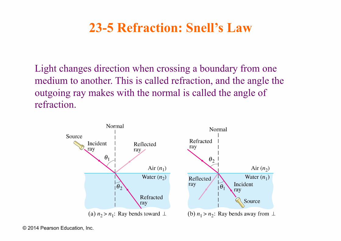
23-5 Refraction: Snell’s Law
Light changes direction when crossing a boundary from one medium to another. This is called refraction, and the angle the outgoing ray makes with the normal is called the angle of refraction.
© 2014 Pearson Education, Inc.
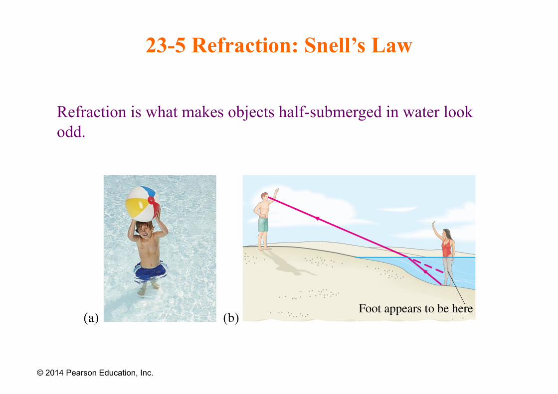
23-5 Refraction: Snell’s Law
Refraction is what makes objects half-submerged in water look odd.
© 2014 Pearson Education, Inc.
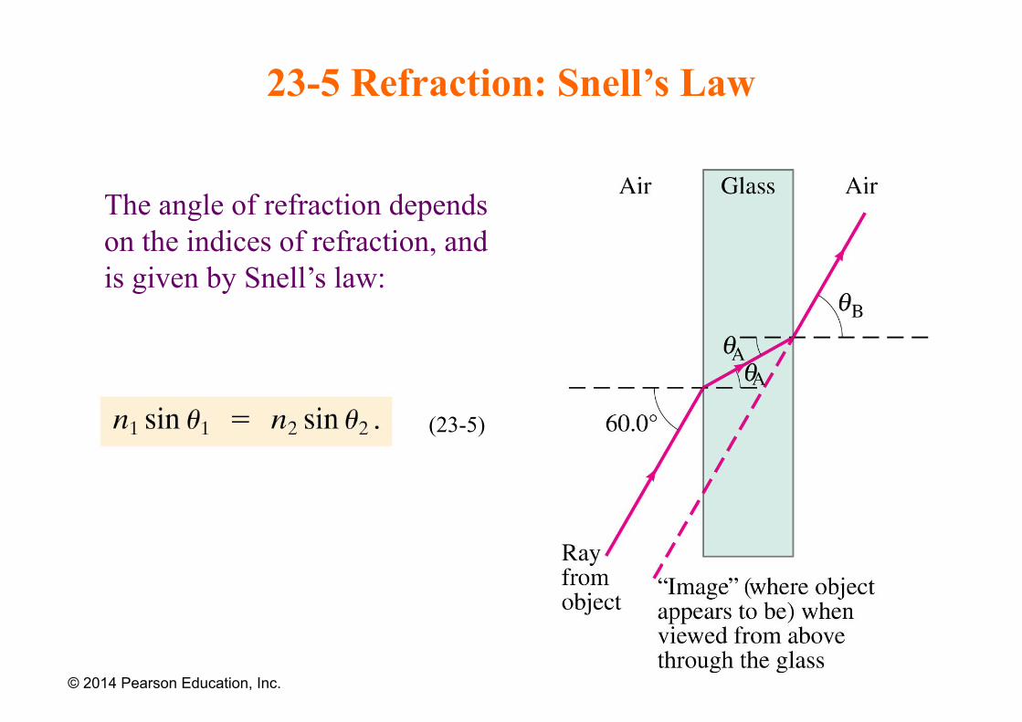
23-5 Refraction: Snell’s Law
The angle of refraction depends on the indices of refraction, and is given by Snell’s law:
© 2014 Pearson Education, Inc.
(23-5)
Example
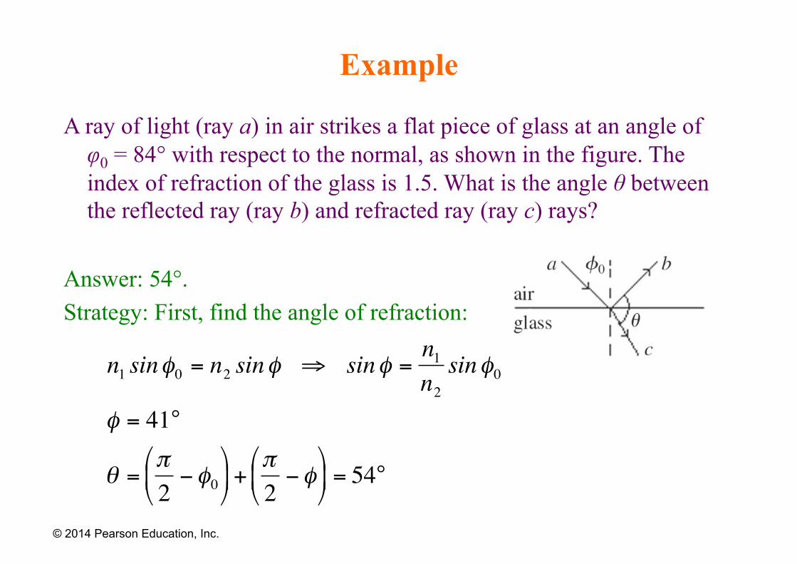
A ray of light (ray a) in air strikes a flat piece of glass at an angle of φ0 = 84° with respect to the normal, as shown in the figure. The index of refraction of the glass is 1.5. What is the angle θ between the reflected ray (ray b) and refracted ray (ray c) rays?
Answer: 54°. Strategy: First, find the angle of refraction:
© 2014 Pearson Education, Inc.
€
n1 sinφ0 = n2 sinφ ⇒ sinφ =n1n2sinφ0
φ = 41°
θ =π2−φ0
⎛
⎝ ⎜
⎞
⎠ ⎟ +
π2−φ
⎛
⎝ ⎜
⎞
⎠ ⎟ = 54°
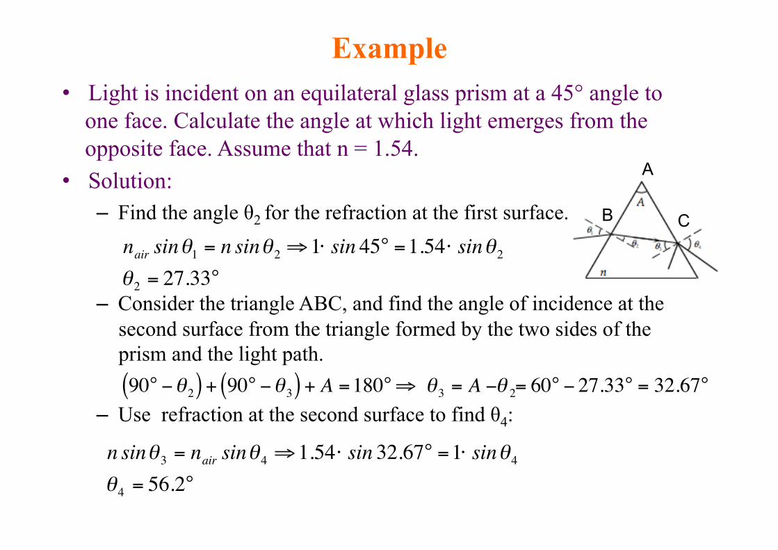
• Light is incident on an equilateral glass prism at a 45° angle to one face. Calculate the angle at which light emerges from the opposite face. Assume that n = 1.54.
• Solution: – Find the angle θ2 for the refraction at the first surface.
– Consider the triangle ABC, and find the angle of incidence at the second surface from the triangle formed by the two sides of the prism and the light path.
– Use refraction at the second surface to find θ4:
Example
€
nair sinθ1 = n sinθ2 ⇒1⋅ sin 45° =1.54⋅ sinθ2θ2 = 27.33°
€
90° −θ2( ) + 90° −θ3( ) + A =180°⇒ θ3 = A −θ 2= 60° − 27.33° = 32.67°
€
n sinθ3 = nair sinθ4 ⇒1.54⋅ sin 32.67° =1⋅ sinθ4θ4 = 56.2°
B C
A
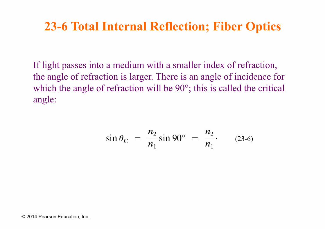
23-6 Total Internal Reflection; Fiber Optics
If light passes into a medium with a smaller index of refraction, the angle of refraction is larger. There is an angle of incidence for which the angle of refraction will be 90°; this is called the critical angle:
© 2014 Pearson Education, Inc.
(23-6)
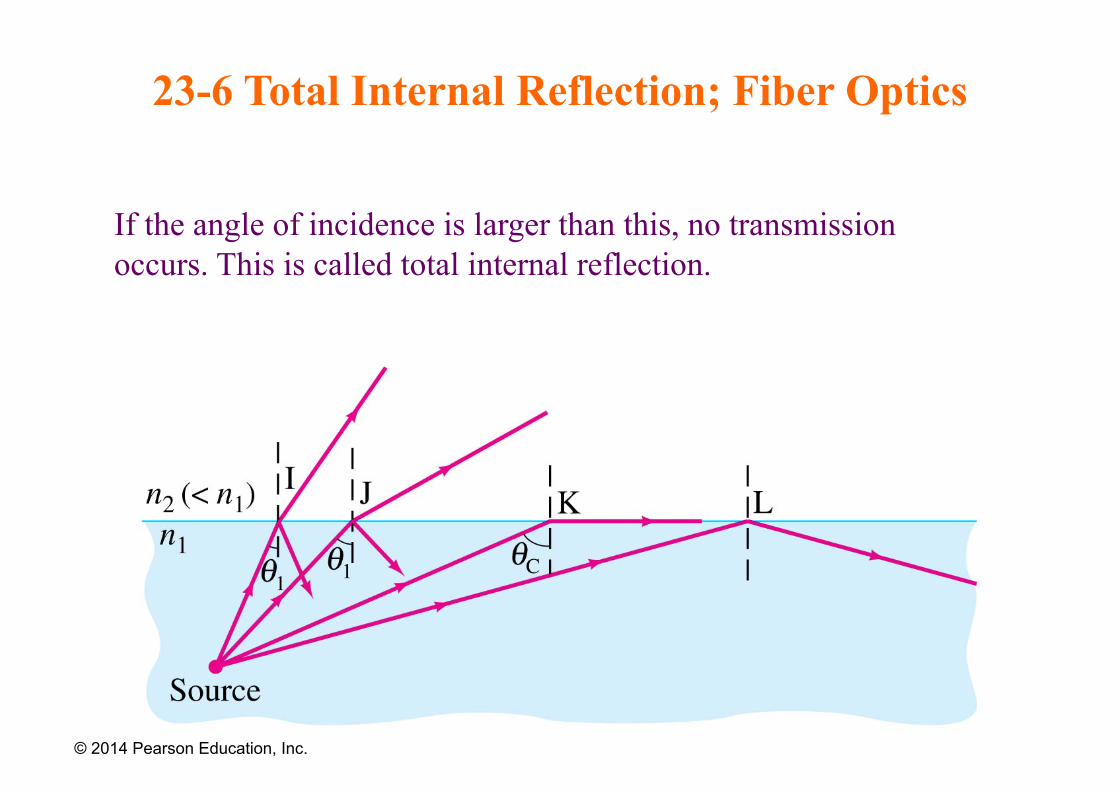
23-6 Total Internal Reflection; Fiber Optics
If the angle of incidence is larger than this, no transmission occurs. This is called total internal reflection.
© 2014 Pearson Education, Inc.
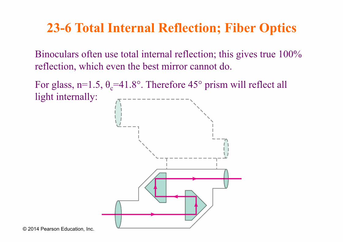
23-6 Total Internal Reflection; Fiber Optics
Binoculars often use total internal reflection; this gives true 100% reflection, which even the best mirror cannot do.
For glass, n=1.5, θc=41.8°. Therefore 45° prism will reflect all light internally:
© 2014 Pearson Education, Inc.
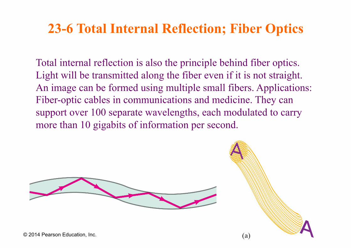
23-6 Total Internal Reflection; Fiber Optics
Total internal reflection is also the principle behind fiber optics. Light will be transmitted along the fiber even if it is not straight. An image can be formed using multiple small fibers. Applications: Fiber-optic cables in communications and medicine. They can support over 100 separate wavelengths, each modulated to carry more than 10 gigabits of information per second.
© 2014 Pearson Education, Inc.
Example
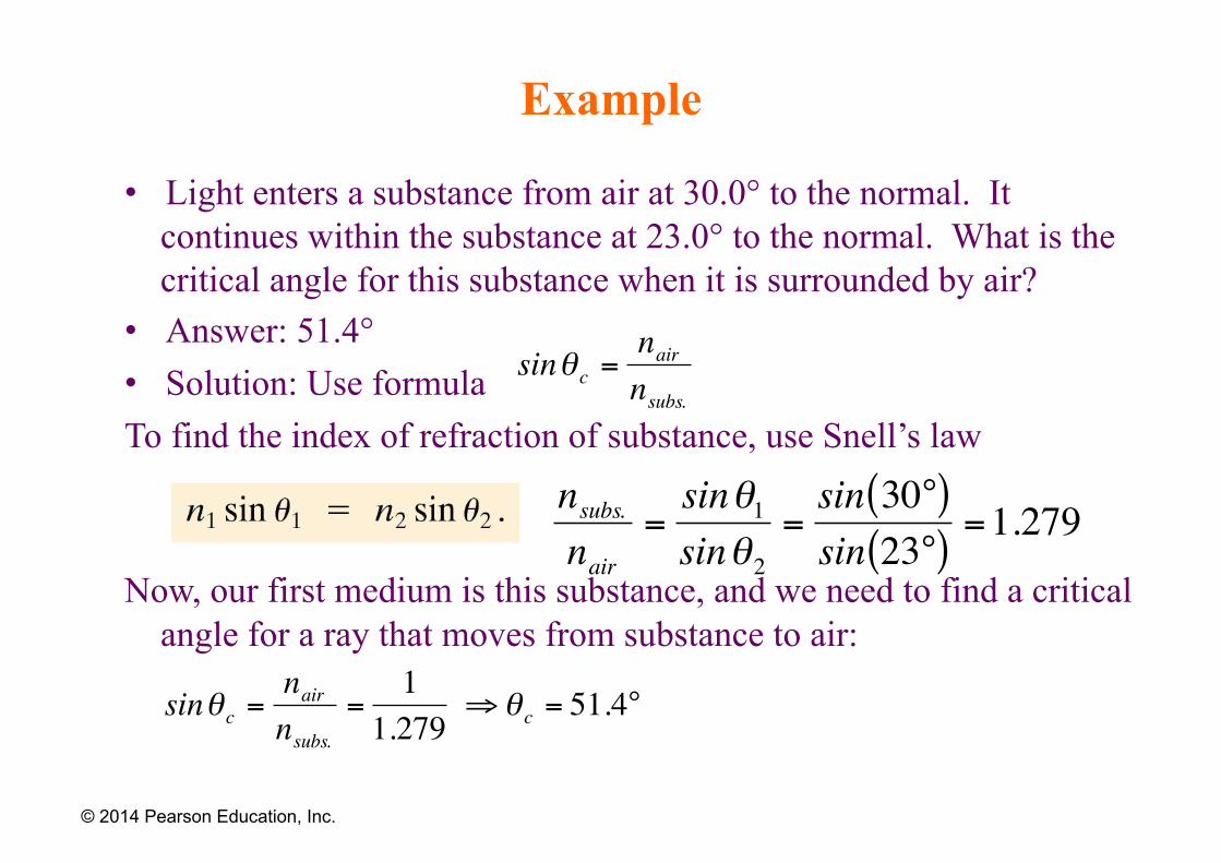
• Light enters a substance from air at 30.0° to the normal. It continues within the substance at 23.0° to the normal. What is the critical angle for this substance when it is surrounded by air?
• Answer: 51.4° • Solution: Use formula To find the index of refraction of substance, use Snell’s law
Now, our first medium is this substance, and we need to find a critical angle for a ray that moves from substance to air:
© 2014 Pearson Education, Inc.
€
nsubs.nair
=sinθ1sinθ2
=sin 30°( )sin 23°( )
=1.279
€
sinθ c =nairnsubs.
=1
1.279⇒θ c = 51.4°
€
sinθ c =nairnsubs.
23-7 Thin Lenses; Ray Tracing
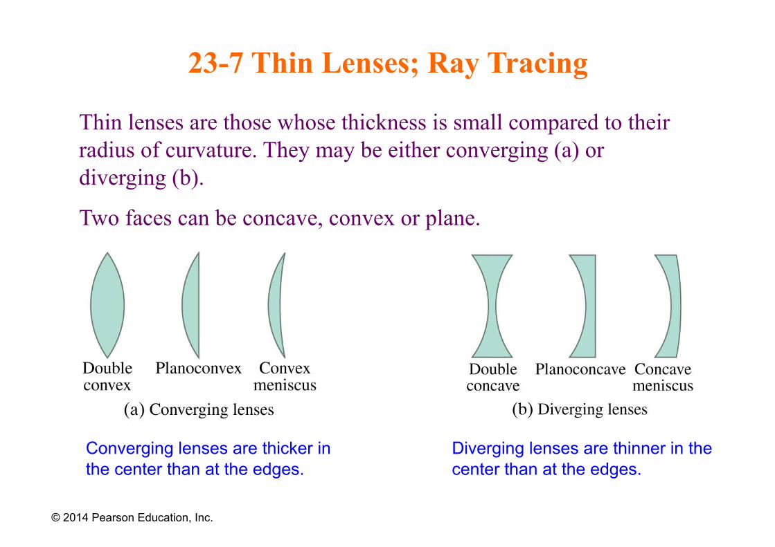
Thin lenses are those whose thickness is small compared to their radius of curvature. They may be either converging (a) or diverging (b).
Two faces can be concave, convex or plane.
© 2014 Pearson Education, Inc.
Converging lenses are thicker in the center than at the edges.
Diverging lenses are thinner in the center than at the edges.
23-7 Thin Lenses; Ray Tracing
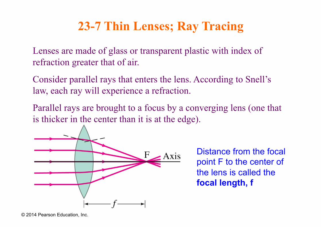
Lenses are made of glass or transparent plastic with index of refraction greater that of air.
Consider parallel rays that enters the lens. According to Snell’s law, each ray will experience a refraction.
Parallel rays are brought to a focus by a converging lens (one that is thicker in the center than it is at the edge).
© 2014 Pearson Education, Inc.
Distance from the focal point F to the center of the lens is called the focal length, f
23-7 Thin Lenses; Ray Tracing
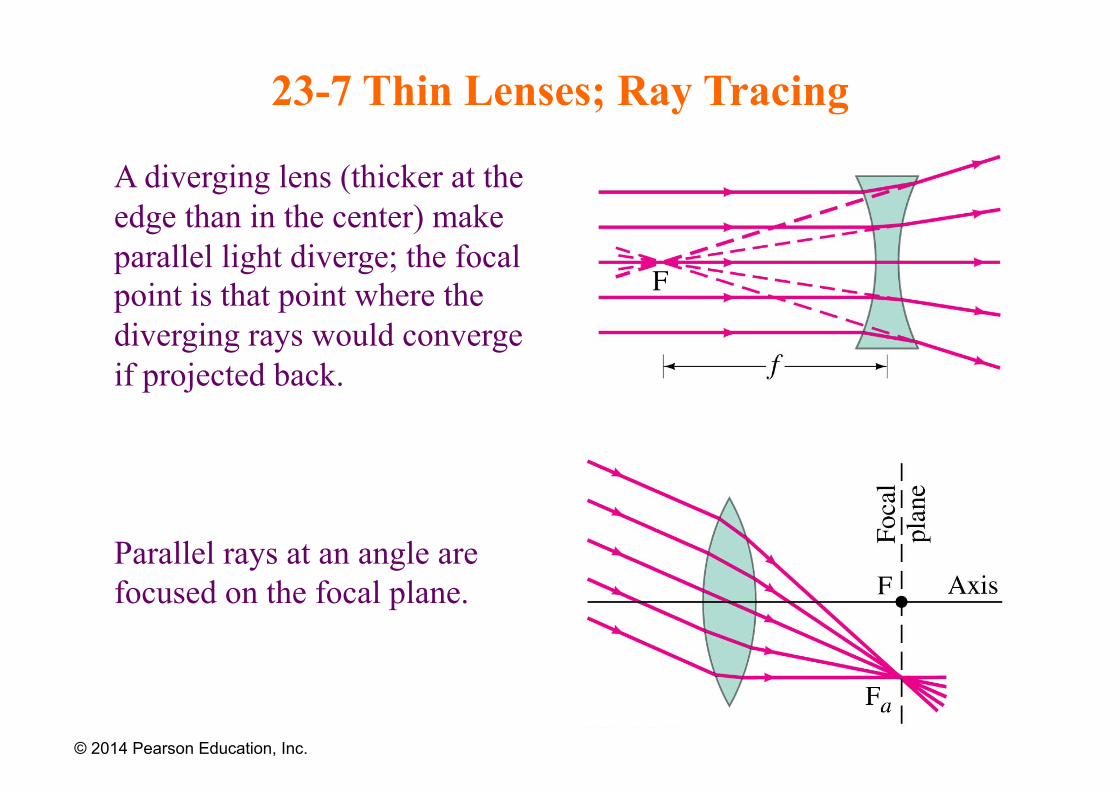
A diverging lens (thicker at the edge than in the center) make parallel light diverge; the focal point is that point where the diverging rays would converge if projected back.
Parallel rays at an angle are focused on the focal plane.
© 2014 Pearson Education, Inc.
23-7 Thin Lenses; Ray Tracing
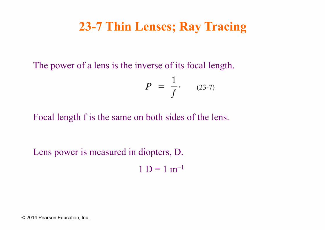
The power of a lens is the inverse of its focal length.
Focal length f is the same on both sides of the lens.
Lens power is measured in diopters, D.
1 D = 1 m−1
© 2014 Pearson Education, Inc.
(23-7)
23-7 Thin Lenses; Ray Tracing
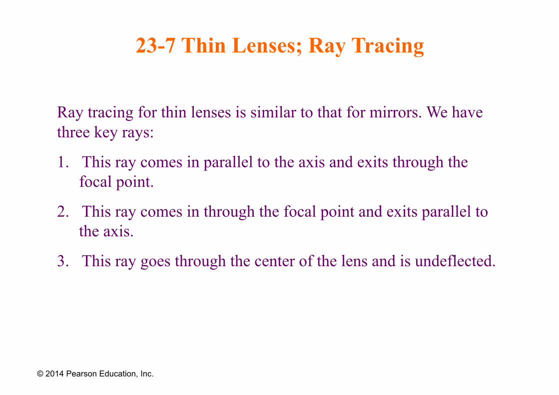
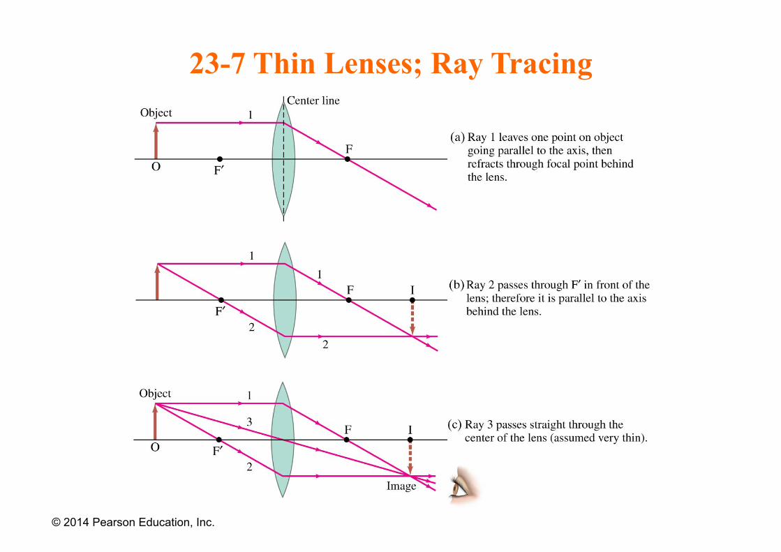
Ray tracing for thin lenses is similar to that for mirrors. We have three key rays:
1. This ray comes in parallel to the axis and exits through the focal point.
2. This ray comes in through the focal point and exits parallel to the axis.
3. This ray goes through the center of the lens and is undeflected.
© 2014 Pearson Education, Inc.
23-7 Thin Lenses; Ray Tracing
© 2014 Pearson Education, Inc.
23-7 Thin Lenses; Ray Tracing
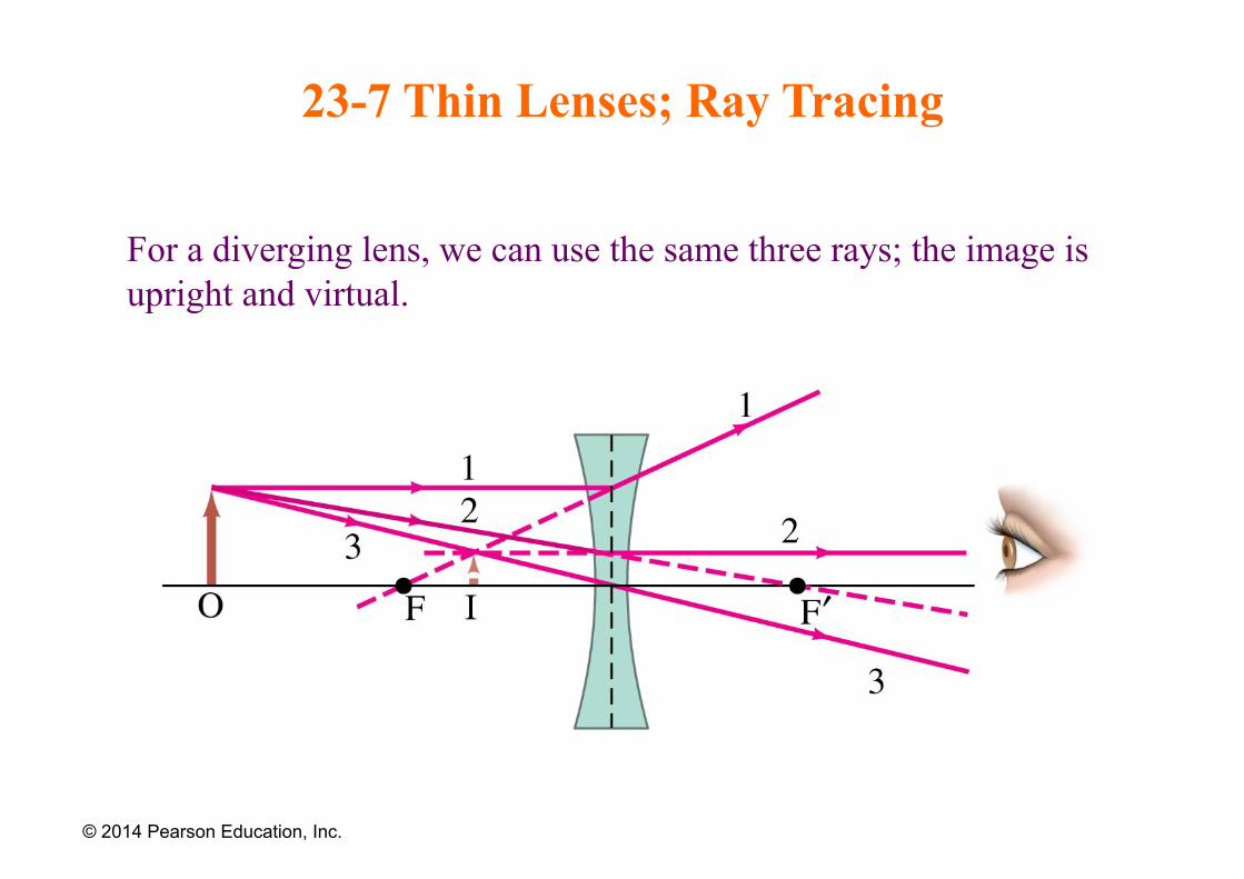
For a diverging lens, we can use the same three rays; the image is upright and virtual.
© 2014 Pearson Education, Inc.
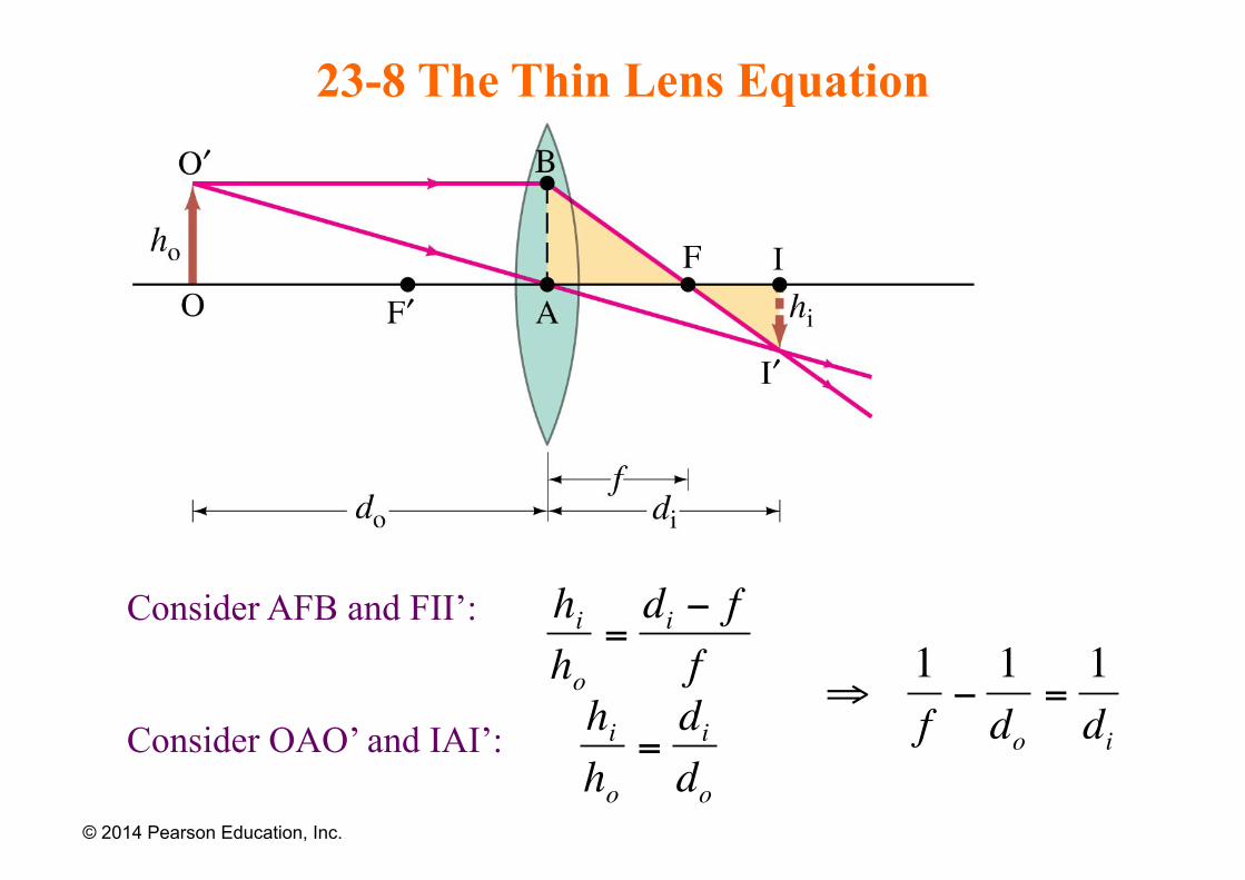
23-8 The Thin Lens Equation
Consider AFB and FII’:
Consider OAO’ and IAI’:
© 2014 Pearson Education, Inc.
€
hiho
=di − ff
hiho
=dido
⇒1f−1do
=1di
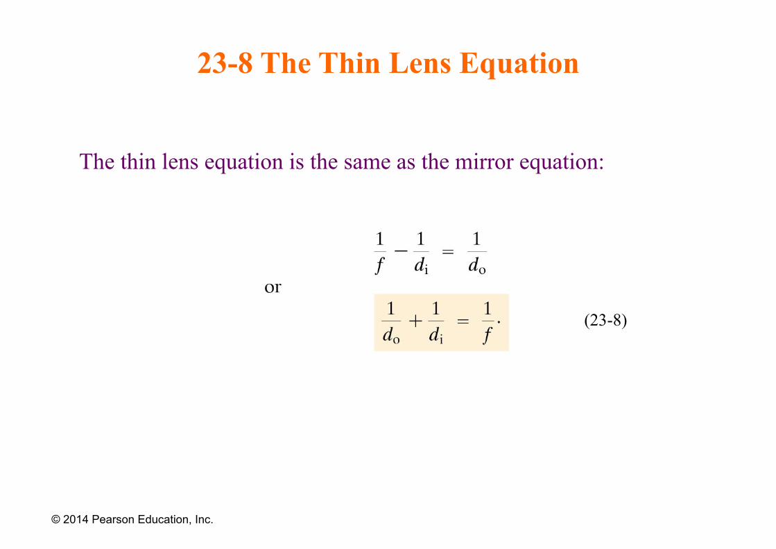
23-8 The Thin Lens Equation
The thin lens equation is the same as the mirror equation:
© 2014 Pearson Education, Inc.
(23-8)
23-8 The Thin Lens Equation
The sign conventions are slightly different:
1. The focal length is positive for converging lenses and negative for diverging.
2. The object distance is positive when the object is on the same side as the light entering the lens (not an issue except in compound systems); otherwise it is negative.
3. The image distance is positive if the image is on the opposite side from the light entering the lens; otherwise it is negative.
4. The height of the image is positive if the image is upright and negative otherwise.
© 2014 Pearson Education, Inc.
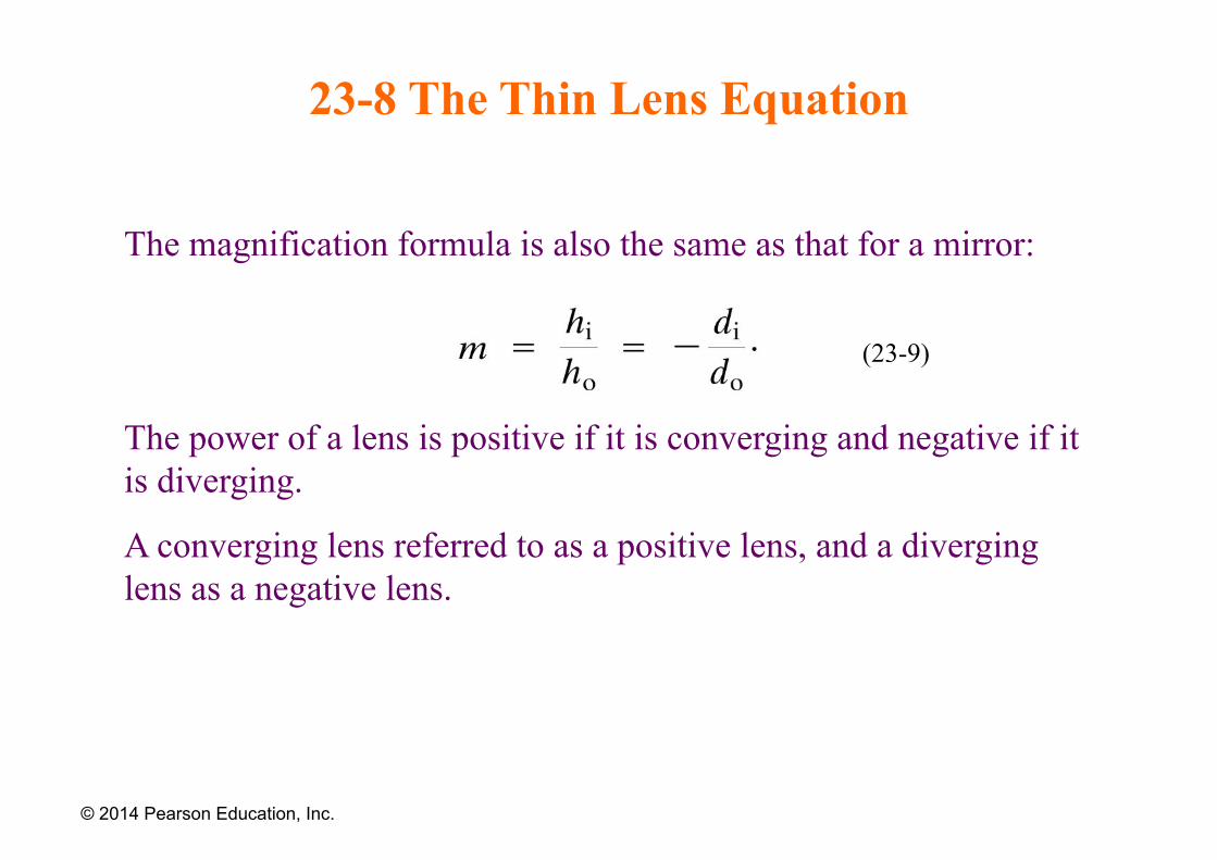
23-8 The Thin Lens Equation
The magnification formula is also the same as that for a mirror:
The power of a lens is positive if it is converging and negative if it is diverging.
A converging lens referred to as a positive lens, and a diverging lens as a negative lens.
© 2014 Pearson Education, Inc.
(23-9)
23-8 The Thin Lens Equation
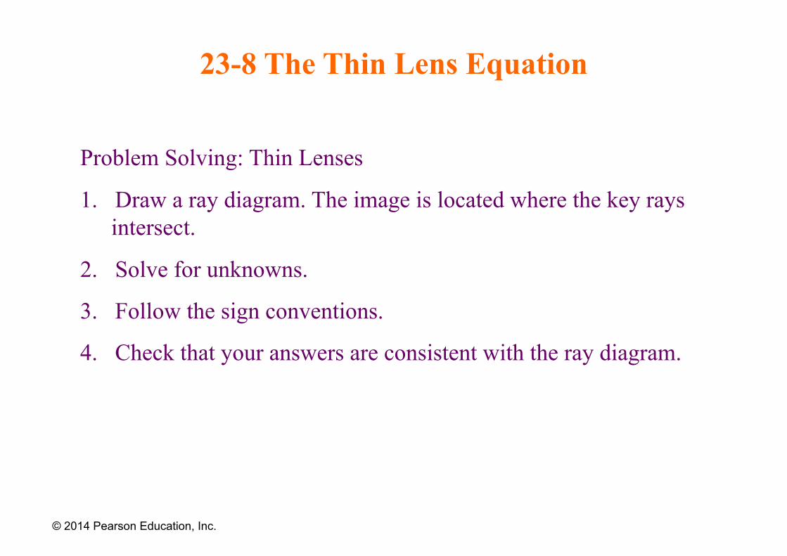
Problem Solving: Thin Lenses
1. Draw a ray diagram. The image is located where the key rays intersect.
2. Solve for unknowns.
3. Follow the sign conventions.
4. Check that your answers are consistent with the ray diagram.
© 2014 Pearson Education, Inc.
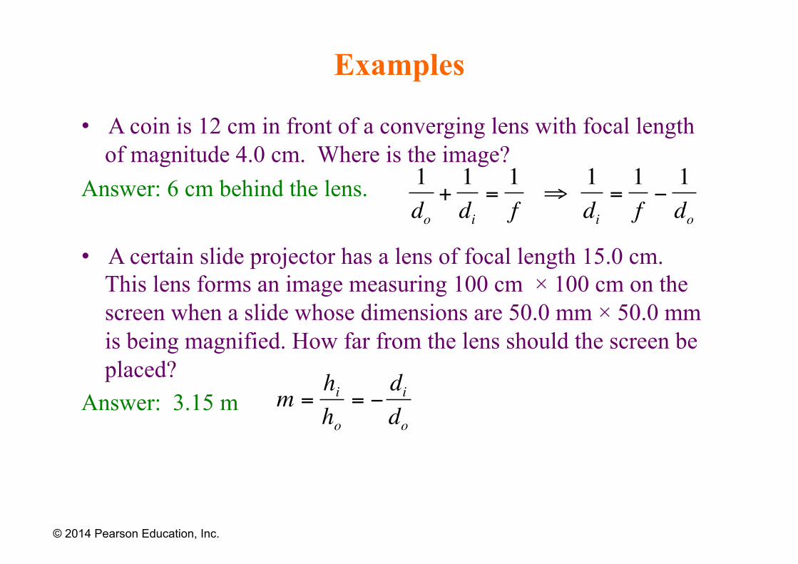
Examples
• A coin is 12 cm in front of a converging lens with focal length of magnitude 4.0 cm. Where is the image?
Answer: 6 cm behind the lens.
• A certain slide projector has a lens of focal length 15.0 cm. This lens forms an image measuring 100 cm × 100 cm on the screen when a slide whose dimensions are 50.0 mm × 50.0 mm is being magnified. How far from the lens should the screen be placed?
Answer: 3.15 m
© 2014 Pearson Education, Inc.
€
1do
+1di
=1f
⇒1di
=1f−1do
€
m =hiho
= −dido
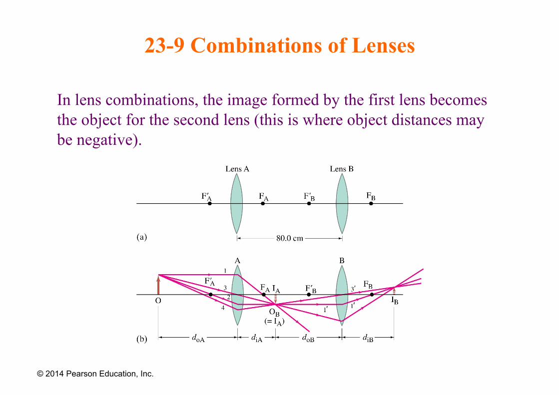
23-9 Combinations of Lenses
In lens combinations, the image formed by the first lens becomes the object for the second lens (this is where object distances may be negative).
© 2014 Pearson Education, Inc.
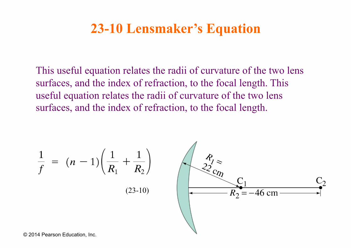
23-10 Lensmaker’s Equation
This useful equation relates the radii of curvature of the two lens surfaces, and the index of refraction, to the focal length. This useful equation relates the radii of curvature of the two lens surfaces, and the index of refraction, to the focal length.
© 2014 Pearson Education, Inc.
(23-10)
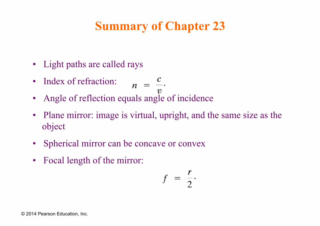
Summary of Chapter 23
• Light paths are called rays
• Index of refraction:
• Angle of reflection equals angle of incidence
• Plane mirror: image is virtual, upright, and the same size as the object
• Spherical mirror can be concave or convex
• Focal length of the mirror:
© 2014 Pearson Education, Inc.
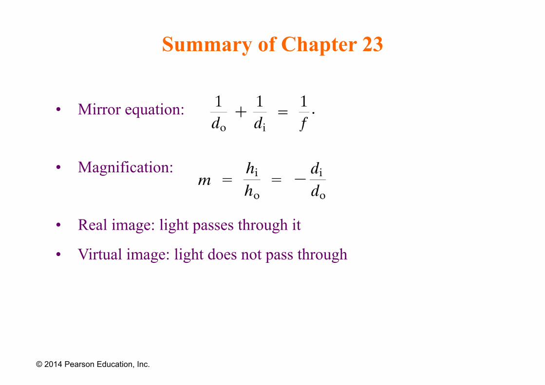
Summary of Chapter 23
• Mirror equation:
• Magnification:
• Real image: light passes through it
• Virtual image: light does not pass through
© 2014 Pearson Education, Inc.
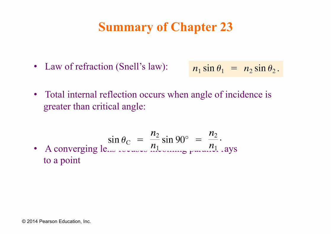
Summary of Chapter 23
• Law of refraction (Snell’s law):
• Total internal reflection occurs when angle of incidence is greater than critical angle:
• A converging lens focuses incoming parallel rays to a point
© 2014 Pearson Education, Inc.
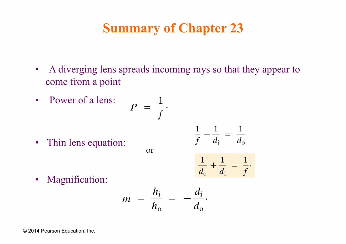
Summary of Chapter 23
• A diverging lens spreads incoming rays so that they appear to come from a point
• Power of a lens:
• Thin lens equation:
• Magnification:
© 2014 Pearson Education, Inc.