Embed Size (px)
Citation preview

12/28/2015
1
Pile FOUNDATION
By
Dr. Yavuz YARDIM
Dept. of Civil Engineering
14 December 2015
Foundation
Foundation
Pad Footing
Combined Footing
Raft Footing
Wall / strip Footing
Pile Foundation

12/28/2015
2
12/28/2015
3

12/28/2015
4

12/28/2015
5
12/28/2015
6

12/28/2015
7
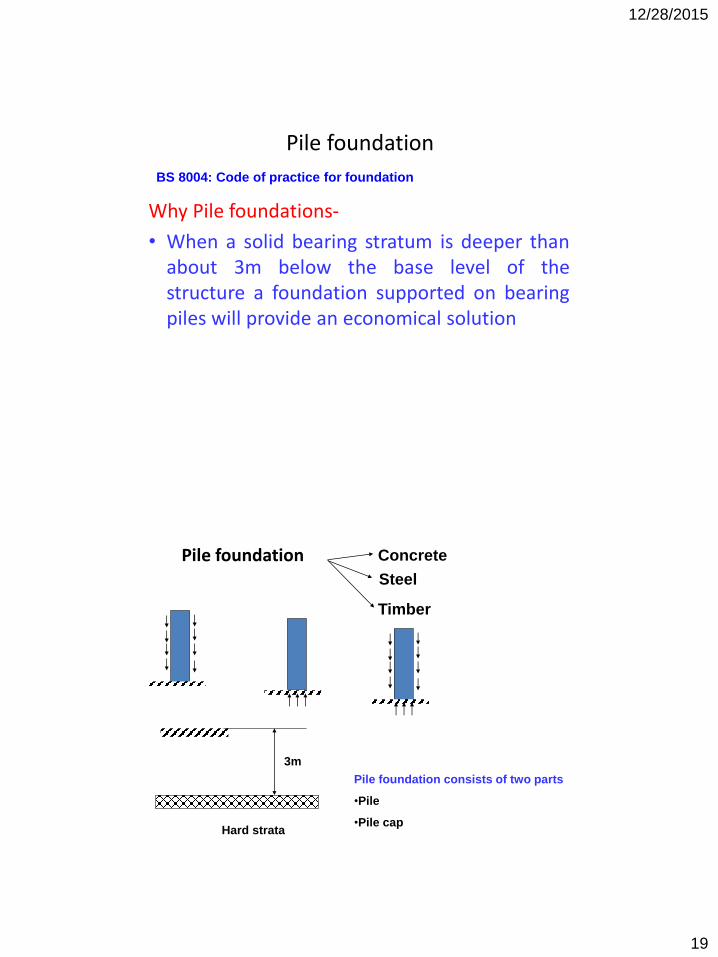
Pile foundation Concrete
Steel
Timber
Hard strata
3m
Pile foundation consists of two parts
•Pile
•Pile cap

12/28/2015
8

12/28/2015
9
12/28/2015
10
12/28/2015
11

12/28/2015
12
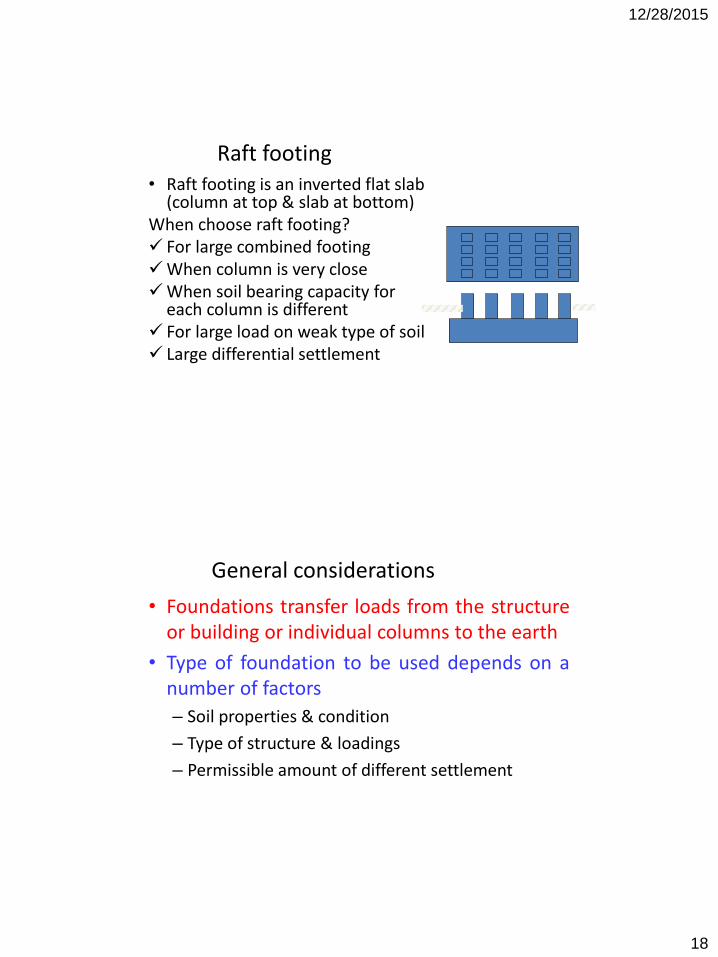
Raft footing• Raft footing is an inverted flat slab
(column at top & slab at bottom) When choose raft footing? For large combined footingWhen column is very closeWhen soil bearing capacity for
each column is different For large load on weak type of soil Large differential settlement

12/28/2015
13

12/28/2015
14

12/28/2015
15

12/28/2015
16

12/28/2015
17
Design Foundation
Related to soil(soil bearing
capacity)
Related to structure
How to choose type of footing
Depends on soil property
Depends on profile of soil
Depends on load
Depends on water table inside the ground
Depends on cost
12/28/2015
18
Raft footing• Raft footing is an inverted flat slab
(column at top & slab at bottom) When choose raft footing? For large combined footingWhen column is very closeWhen soil bearing capacity for
each column is different For large load on weak type of soil Large differential settlement
General considerations
• Foundations transfer loads from the structureor building or individual columns to the earth
• Type of foundation to be used depends on anumber of factors
– Soil properties & condition
– Type of structure & loadings
– Permissible amount of different settlement
12/28/2015
19
Pile foundation
Why Pile foundations-
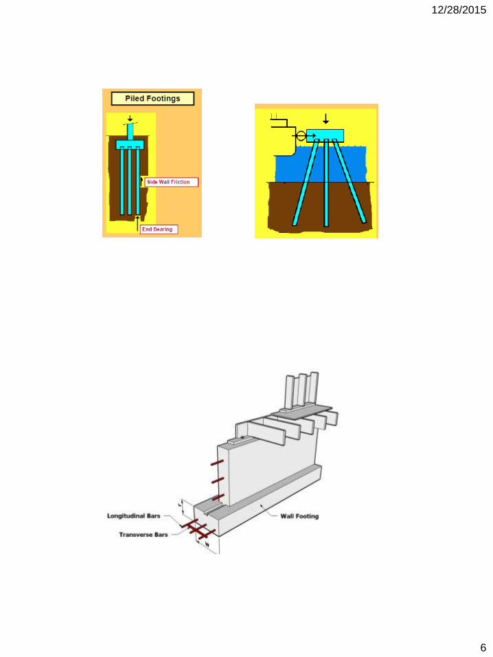
• When a solid bearing stratum is deeper thanabout 3m below the base level of thestructure a foundation supported on bearingpiles will provide an economical solution
BS 8004: Code of practice for foundation
Pile foundation Concrete
Steel
Timber
Hard strata
3m
Pile foundation consists of two parts
•Pile
•Pile cap

12/28/2015
20
100mm
column
Pile cap
Pile
S = not less than2Φ
Φ
Due to Pile arrangement shape of pile cap also different
More economical
More conservative
100mm
Abutment
Pile cap
Pile
Beam / bridge girder
Pile
d= ½SPile cap
Type of
pile cap
Rigid (act as rigid body i.e. move as one unit
Flexible

12/28/2015
21
N = total no. of pile
N1 = total no of pile per row
N2 = total no. of inclined pile per row
S = pile spacing
W = weight of pile cap
P = weight of column / pier
Fv = axial force in the pile due to vertical load
FH = axial force in the pile due to horizontal / lateral load
Fm = axial force in the pile due to moment
F = total force/load of pile = Fv+ FH+ Fm
Calculation of Forces in Pile
Step-1: calculate the forces in each pile due to axial load, lateral load and moment in the column / pier
Step-2: Assume soil confine the pile
Step-3: design the pile as a short column / get the pile size from the table
100mm
Pile cap
Pile
P
W
4321
S S S
R
1R
1
H
h
Vertical load calculation (act at center point of pile cap)
N
WPFV
For vertical pile
N
WPFV
N
WPFV
21cos
R
R
VF
N
WP
Again
cos,
For inclined pile
N
WP
R
1
)R(1 2
FV
FV
R
R
N
WPFV
21

12/28/2015
22
Horizontal / Lateral load calculation
Note:
Horizontal load will be distributed on the inclined piles only, vertical pile
will carry zero horizontal load
For inclined pile
2N
H
R
1
)R(1 2
FH
FH 21
1sin
R
HF
N
H
Again 2sin,
1
1 2
2
R
N
HFH
Moment Force calculation
σ = (Fm/A) = (M/z) = (My / IN.A)
IN.A = I0 + Ad2
Where, A = area of single pile
Take 1st row
I = N1x A.(1.5S)2
Take 2nd row
I = N1 xA.(0.5S)2
Total IN.A = N1 xA[(1.5S)2 + (0.5S)2] x 2 (for
symmetrical axis)
(Fm/A) = (My / IN.A) = [M*y] / [N1 xA[(1.5S)2 +
(0.5S)2] x 2
Fm = [M*y] / [2 N1 [(1.5S)2 + (0.5S)2]
0
Y
100mm
Pile cap
Pile
P
W
4321
S S S
R
1R
1
H
h
M1

12/28/2015
23
R
R
I
yMF
AN
m
2
.
1
)R(1 2
For inclined pile
ANI
yM
.
R
1
Fm
Fm
Total moment M = M1 + Hxh
Where, y - is the distance from the pile cap center (NA) to the individual pile