Embed Size (px)
Citation preview

1-1
Florida International University
Department of Electrical & Computer Engineering
EEL-5270 Electrical Transients in Power Systems
Lecture Notes
Set No. 1
Professor Osama A. Mohammed
Miami, Florida
Spring 2017
EEL-5270 Electrical Transients in Power Systems, Prof. Mohammed, Copyright All rights reserved, 2008-2017
1-2EEL-5270 Electrical Transients in Power Systems, Prof. Mohammed, Copyright All rights reserved, 2008-2017
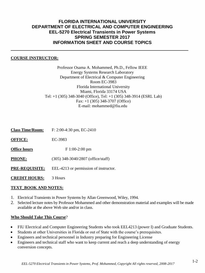
FLORIDA INTERNATIONAL UNIVERSITY DEPARTMENT OF ELECTRICAL AND COMPUTER ENGINEERING
EEL-5270 Electrical Transients in Power Systems SPRING SEMESTER 2017
INFORMATION SHEET AND COURSE TOPICS
COURSE INSTRUCTOR:
Professor Osama A. Mohammed, Ph.D., Fellow IEEE
Energy Systems Research Laboratory
Department of Electrical & Computer Engineering
Room EC-3983
Florida International University
Miami, Florida 33174 USA
Tel: +1 (305) 348-3040 (Office), Tel: +1 (305) 348-3914 (ESRL Lab)
Fax: +1 (305) 348-3707 (Office)
E-mail: [email protected]
Class Time/Room: F: 2:00-4:30 pm, EC-2410
OFFICE: EC-3983
Office hours F 1:00-2:00 pm
PHONE: (305) 348-3040/2807 (office/staff)
PRE-REQUISITE: EEL-4213 or permission of instructor.
CREDIT HOURS: 3 Hours
TEXT_BOOK AND NOTES:
1. Electrical Transients in Power Systems by Allan Greenwood, Wiley, 1994.
2. Selected lecture notes by Professor Mohammed and other demonstration material and examples will be made
available at the above Web site and/or in class.
Who Should Take This Course?
FIU Electrical and Computer Engineering Students who took EEL4213 (power I) and Graduate Students.
Students at other Universities in Florida or out of State with the course’s prerequisites.
Engineers and technical personnel in Industry preparing for Engineering License
Engineers and technical staff who want to keep current and reach a deep understanding of energy
conversion concepts.

1-3
Objectives:
1. Introducing Electrical Transients in power systems
2. Cover the concepts of traveling waves and propagation
3. Modeling of transmission lines as distributed parameter systems.
4. Discuss issues related to insulation coordination, grounding and limiting of surge effects
5. Develop techniques related to reflections at transition points in lines and cables
6. Multi conductor transients and distributed parameter modeling for components and shielding issues.
7. Involve students in a practical experience through the term project.
Course topics:
Introduction to Electrical Transients in Power Systems (Circuit opening and closing transients, Recovery
transients.
Traveling waves on Transmission Systems (Propagation of Surges)
Modeling of Transmission Lines by Distributed Parameter Concepts (Lossles cases, loss cases,
distrotionless cases, Lines with small losses)
Distortion due to Corona
Energy in Traveling Waves
Characteristics of Traveling Waves (wave shapes, standards, impulse and switching surges, lightning,
Basic Impulse Insulation Level (BIL), Flashover surge generators)
Analytical approximation of Surge Wave Shapes
Transition Points (Lines, Cables, Voltage Buildup, various types of Transition points, terminations)
Lumped Series and Shunt Impedance Transition Points (Junctions at Cables, Substations
Dissimilar Voltage and Current Surges
Surge Arresters (Linear and Nonlinear Characteristics.
Successive Reflections on Transmission Systems
Grounding
Insulation Coordination
Multi-Conductor, Multi-velocity Systems
Transient Performance of Distributed parameter Systems for Transformer, Generator and Motor
Windings
Shielding
Practical Examples, projects
References:
Appropriate lists and copies of technical papers will be distributed or listed for your collection. A list of recent
text-books and other technical record will be suggested to you. However, you are also required to research and
obtained other pertinent materials related to the topics covered.
ASSISTANCE: Please try to see Dr. Mohammed during his listed office hours or through the communication
forum on the web page. If this proves impossible, a personal appointment should arranged by calling my direct
phone number or the ECE department secretary at extension (305-348-2807).
ABSENCE: Class attendance (physical or virtual) is very important and is considered in your overall
performance in the course. Students are responsible for all material covered in that class.
EEL-5270 Electrical Transients in Power Systems, Prof. Mohammed, Copyright All rights reserved, 2008-2017

1-4
IMPORTANT RULE: Students are encouraged to discuss the course topics with the professor and with each
other. Any work submitted (Homework, Tests, projects, etc.) should be pledged and signed as the students' own
work, and that there is no any unauthorized help was obtained. Violators will be subject to academic misconduct,
which might lead to dismissal from the university.
GRADING POLICY:
Homework will be assigned regularly, collected and graded. Efforts in homework indicate that you are studying
and caring about the course and therefore can have an impact on your final grade. Time for the mid-term will be
announced one week in advance. Any work submitted must be neat and detailed for partial mark. Your Grade
will be calculated as Follows:
Homework and Class Projects 20%
Mid Term 25%
Term Project/Research Paper 20%
Final Exam 35%
_______
Total 100%
TERM PROJECT:
The project will involve one or more of the topics of this course. Final presentation (oral and written) of the
overall project results will be required. Software available for this class can be utilized for the projects.
EEL-5270 Electrical Transients in Power Systems, Prof. Mohammed, Copyright All rights reserved, 2008-2017

1-5
The Electromagnetic Pulse (EMP) Effect
EEL-5270 Electrical Transients in Power Systems, Prof. Mohammed, Copyright All rights reserved, 2008-2017

1-6
The Influence of a Charged Cloud
EEL-5270 Electrical Transients in Power Systems, Prof. Mohammed, Copyright All rights reserved, 2008-2017

1-7
I. HOW LIGHTNING IS FORMED
AVERAGE THUNDERCLOUD USUALLY BOTTOMS AROUND 2 MILES (10,000 )
AND TOPS OUT AROUND 8 MILES (50,000feet) IN ELEVATION.
TEMPERATURE IS ABOUT 40oF AT BASE
T0 -65 o AT THE TOP.
WARM MOIST AIR ON LEADING EDGE
ASCENDS RAPIDLY FROM 40oF TO -65oF
FORMING ICE CRYSTALS AND WATER
DROPLETS.
IT IS THIS RAPID ASCENT AND
SWIRLING MOTION THAT FORMS THE
ELECTRIC CHARGE. EEL-5270 Electrical Transients in Power Systems, Prof. Mohammed, Copyright All rights reserved, 2008-2017

1-8
THIS CREATES A HIGHLY POSITIVE CHARGE
IN THE TOP OF THE CLOUD (6 MILES AT
-65ºF), A HIGHLY NEGATIVE CHARGE IN THE
LOWER CENTRAL PART (3 MILES AT 0ºF) AND
A SMALL POSITIVE CHARGE AT THE BASE (2
MILES AT 40ºF). THE DIFFERENCES IN
POTENTIAL RESULTS IN THE LIGHTNING
STROKE.
EEL-5270 Electrical Transients in Power Systems, Prof. Mohammed, Copyright All rights reserved, 2008-2017
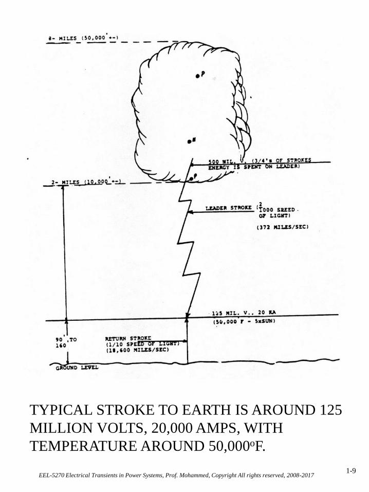
1-9
TYPICAL STROKE TO EARTH IS AROUND 125
MILLION VOLTS, 20,000 AMPS, WITH
TEMPERATURE AROUND 50,000oF.
EEL-5270 Electrical Transients in Power Systems, Prof. Mohammed, Copyright All rights reserved, 2008-2017

1-10
POINTS OF INTEREST
YOU CAN TELL HOW NEAR THE
STORM IS BY COUNTING THE
SECONDS BETWEEN LIGHNING AND
THUNDER. DIVIDE THE NUMBER OF
SECONDS BY 5.
THUNDERSTORMS ARE
RESPONSIBLE FOR MAINTAINING
EARTH’S NEGATIVE CHARGE.
LIGHTNING PRODUCES NITROGEN
COMPOUNDS THAT ARE ESSENTIAL
FOR MOST PLANTS.
LIGHTNING KILLS MORE PEOPLE IN
THE U.S. EVERY YEAR THAN
TORNADOES, HURRICANES, OR
FLOODS.
EEL-5270 Electrical Transients in Power Systems, Prof. Mohammed, Copyright All rights reserved, 2008-2017

1-11EEL-5270 Electrical Transients in Power Systems, Prof. Mohammed, Copyright All rights reserved, 2008-2017

1-12
AVERAGE THUNDERSTORM DAYS PER
YEAR IN U.S.
EEL-5270 Electrical Transients in Power Systems, Prof. Mohammed, Copyright All rights reserved, 2008-2017

EEL-5270 Electrical Transients in Power Systems, Prof. Mohammed, Copyright All rights reserved, 2008-20171-13
ELECTROMAGNETIC COUPLING
ELECTROMAGNETIC COUPLING IS THE MOST
COMMON WAY LIGHNING GETS INTO THE
SYSTEM.
AS A CHARGED CLOUD MOVES INTO THE
AREA (OR BUILDS UP IN THE AREA), THE LINE
BECOMES IMMERSED IN THE
ELECTROSTATIC FIELD.
WHEN LIGHTNING STIKES IN THE VICINITY
(WITHIN A FEW HUNDRED FEET), IT MAY
RESULT IN A COUPLING EFFECT BETWEEN
THE FIELD AROUND THE STROKE AND THE
LINE SIMILAR TO THE WAY THE COILS OF A
TRANSFORMER OPERATE.
THIS RESULTS IN OVERVOLTAGES (SURGES)
ON THE LINE WHICH TRAVEL UNTIL IT FINDS
A PATH TO GROUND. THIS POINTS OUT THE
NEED FOR MAINTAINING A GOOD
GROUNDING SYSTEM.

EEL-5270 Electrical Transients in Power Systems, Prof. Mohammed, Copyright All rights reserved, 2008-20171-14
II. HOW LIGHTNING GETS INTO THE SYSTEM
DIRECT HIT

EEL-5270 Electrical Transients in Power Systems, Prof. Mohammed, Copyright All rights reserved, 2008-20171-15
ELECTROMAGNETIC COUPLING - UNDERGROUND
A DIRECT STRIKE TO EARTH IN THE
VICINITY OF BURIED CABLE OR SPILL OVER
FROM THE OH THROUGH THE RISER CAN
CAUSE AN OVERVOLTAGE ON THE
CONCENTRIC CABLE.
WHEN THESE HIGHER VOLTAGES ARE
PRESENT, THE DIFFERENCE IN POTENTIAL
BETWEEN THE PHASE CONDUCTOR AND
CONCENTRIC NEUTRAL CAN RESULT IN
TREEING AND DAMAGED EQUIPMENT.
EEL-5270 Electrical Transients in Power Systems, Prof. Mohammed, Copyright All rights reserved, 2008-20171-16
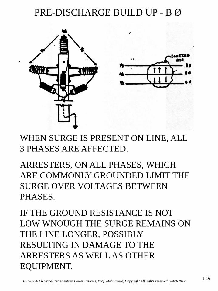
PRE-DISCHARGE BUILD UP - B Ø
WHEN SURGE IS PRESENT ON LINE, ALL
3 PHASES ARE AFFECTED.
ARRESTERS, ON ALL PHASES, WHICH
ARE COMMONLY GROUNDED LIMIT THE
SURGE OVER VOLTAGES BETWEEN
PHASES.
IF THE GROUND RESISTANCE IS NOT
LOW WNOUGH THE SURGE REMAINS ON
THE LINE LONGER, POSSIBLY
RESULTING IN DAMAGE TO THE
ARRESTERS AS WELL AS OTHER
EQUIPMENT.

EEL-5270 Electrical Transients in Power Systems, Prof. Mohammed, Copyright All rights reserved, 2008-20171-17
MULTI-GROUNDED WYE CIRCUITS
MULTI-GROUNDED WYE CIRCUITS DEPEND
ON INTERMEDIATE LOW RESISTANCE
GROUND STATIONS FOR THE SYSTEM TO
OPERATE PROPERLY UNDER ABNORMAL
CONDITIONS. BECAUSE OF HIGH SURGE
IMPEDENCE IN THE NEUTRAL CONDUCTOR,
IT SHOULD NOT BE COUNTED ON TO
DISSIPATE THE SURGE & OVERVOLTAGES OR
TO CARRY THE SURGES TO THE SUBSTATION
FOR DISSIPATION.

EEL-5270 Electrical Transients in Power Systems, Prof. Mohammed, Copyright All rights reserved, 2008-20171-18

EEL-5270 Electrical Transients in Power Systems, Prof. Mohammed, Copyright All rights reserved, 2008-20171-19

EEL-5270 Electrical Transients in Power Systems, Prof. Mohammed, Copyright All rights reserved, 2008-20171-20

EEL-5270 Electrical Transients in Power Systems, Prof. Mohammed, Copyright All rights reserved, 2008-20171-21

EEL-5270 Electrical Transients in Power Systems, Prof. Mohammed, Copyright All rights reserved, 2008-20171-22
Comparison of various distribution line protective measures.

EEL-5270 Electrical Transients in Power Systems, Prof. Mohammed, Copyright All rights reserved, 2008-20171-23
B.I.L. - BASIC IMPULSE INSULATION LEVEL
THE ABILITY OF ANY MATERIAL OR DEVICE TO
WITHSTAND A PRE-DETERMINED IMPULSE LEVEL.
EXAMPLES:
PIN INSULATOR - 100 KV
35 KV INSULATOR (POST) - 180 KV
ANY POLE IN SALT SPRAY AREA - 0 KV
CONCRETE POLE - 0 KV
WOOD POLE
WET - 75 KV/FT
DRY - 100 KV/FT
WOOD X-ARM
WET - 75 KV
DRY - 100 KV/FT
AIR - 186 KV/FT
13 KV TRANSFORMER - 95 KV
23 KV TRANSFORMER - 125 KV

EEL-5270 Electrical Transients in Power Systems, Prof. Mohammed, Copyright All rights reserved, 2008-20171-24
B.I.L. - BASIC IMPULSE INSULATION LEVEL
BIL OF 35 KV SKIRTED INSULATOR IS 180 KV -
WHEN BOLT EXTENDS OUT TO COVER 2 - 3
SKIRTS, BIL IS REDUCED.
EXAMPLE: BOLTS EXTENDS OVER 3 SKIRTS
180 KV - 90 KV = 90 KV
AIR GAP BETWEEN BOLT & INSULATOR = 1 +
INSULATIONS VALUE OF AIR = 15 KV PER 1
THEREFORE BIL IS APPROXIMATELY 105 KV

EEL-5270 Electrical Transients in Power Systems, Prof. Mohammed, Copyright All rights reserved, 2008-20171-25
B.I.L. - BASIC IMPULSE INSULATION LEVEL
CONCRETE POLE
35 KV INSULATOR - 180 KV
CONCRETE POLE - _ 0___
TOTAL BIL 180 KV
WOOD POLE
35 KV INSULATOR - 180 KV
WOOD POLE (WET) - 75 KV/FT
75 KV 180 KV
x_ 3_ 225 KV
225 KV TOTAL BIL 405 KV
EEL-5270 Electrical Transients in Power Systems, Prof. Mohammed, Copyright All rights reserved, 2008-20171-26
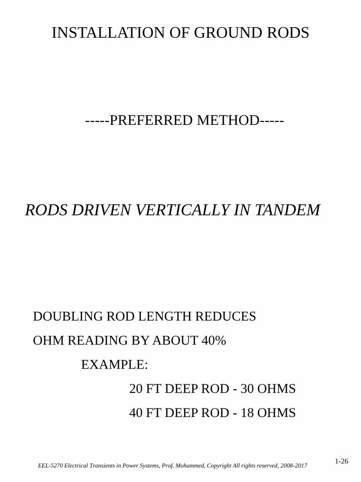
INSTALLATION OF GROUND RODS
-----PREFERRED METHOD-----
RODS DRIVEN VERTICALLY IN TANDEM
DOUBLING ROD LENGTH REDUCES
OHM READING BY ABOUT 40%
EXAMPLE:
20 FT DEEP ROD - 30 OHMS
40 FT DEEP ROD - 18 OHMS

EEL-5270 Electrical Transients in Power Systems, Prof. Mohammed, Copyright All rights reserved, 2008-20171-27
INSTALLATION OF GROUND RODS
ALTERNATIVE TO DEEP DRIVEN ROD
CLUSTERED RODS - MULTIPLE RODS DRIVEN
IN PARALLEL AND
CONNECTED TOGETHER
- WHEN -
ONLY WHEN INITIAL ROD(S) ARE DRIVEN TO
REFUSAL BEFORE SPECIFIED RESISTANCE IS
REACHED

EEL-5270 Electrical Transients in Power Systems, Prof. Mohammed, Copyright All rights reserved, 2008-20171-28
ALTERNATIVE TO DEEP DRIVEN ROD
INSTALL GROUND ROD AT ANGLE
RECOMMENDED ONLY FOR AREAS WHERE
HARD ROCK PROHIBITS DRIVING RODS
VERTICALLY DEEP ENOUGH TO ACHIEVE
SPECIFIED OHMS.
EXAMPLE:
- ROD DRIVEN VERTICALLY TO 20 DEPTH
- WHEN DRIVEN AT 45 ANGLE WILL HAVE
28 OF ROD IN CONTACT WITH EARTH
MAY LOWER RESISTANCE BY 20% - 40% OVER
RODS DRIVEN VERTICALLY

EEL-5270 Electrical Transients in Power Systems, Prof. Mohammed, Copyright All rights reserved, 2008-20171-29
TESTING OF GROUND RODS
EQUIPMENT
FUSE TESTER
VIBOGROUNG ( M&S #590-54700-5)
MEGGER EARTH TESTER
(M&S #590-56000-1)

EEL-5270 Electrical Transients in Power Systems, Prof. Mohammed, Copyright All rights reserved, 2008-20171-30
EARTH RESISTANCE VS. INSULATION
RESISTANCE METERS
EARTH RESISTANCE METERS OPERATE ON
FREQUENCIES BETWEEN 97 Hz AND 125 Hz.
INSULATION RESISTANCE METERS
OPERATE ON FREQ. IN 60 Hz RANGE.
INSULATION RESISTANCE METERS ARE
SUSCEPTIBLE TO STRAY GROUND
CURRENTS OR D.C. CURRENTS WHICH
INFLUENCE READINGS.
INSULATION RESISTANCE METERS ARE
NOT TO BE USED FOR EARTH RESISTANCE
TESTING.

EEL-5270 Electrical Transients in Power Systems, Prof. Mohammed, Copyright All rights reserved, 2008-20171-31
FUSE TESTER
3 AMP ------> 25 OHMS
8 AMP ------> 10 OHMS
FUSE IS DESIGN TO BLOW AT 1 - 1/2
TIMES ITS RATED VALUE
3 AMP FUSE WILL BLOW AT 4-1/2 AMPS
8 AMP FUSE WILL BLOW AT 12 AMPS
OHMS LAW E = R X 1 R = E / 1
R = 115 / 4.5 = 25.5 OHMS
R=RESISTANCE I=CURRENT E=VOLTS

EEL-5270 Electrical Transients in Power Systems, Prof. Mohammed, Copyright All rights reserved, 2008-20171-32
VIBROGROUND AND MEGGER EARTH TESTER
NULL BALANCE INSTRUMENTS
USED FOR MEASURING EARTH
RESISTANCE
METHOD FOR USE:
2 POINT METHOD
3 POINT METHOD

EEL-5270 Electrical Transients in Power Systems, Prof. Mohammed, Copyright All rights reserved, 2008-20171-33
2 POINT (DIRECT METHOD)
MEASURE RESISTANCE BETWEEN
GROUND ROD AND SURROUNDING EARTH
USING THE SYSTEM NEUTRAL AS
REFERENCE.
EEL-5270 Electrical Transients in Power Systems, Prof. Mohammed, Copyright All rights reserved, 2008-20171-34
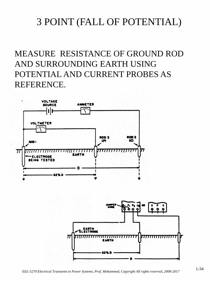
3 POINT (FALL OF POTENTIAL)
MEASURE RESISTANCE OF GROUND ROD
AND SURROUNDING EARTH USING
POTENTIAL AND CURRENT PROBES AS
REFERENCE.

EEL-5270 Electrical Transients in Power Systems, Prof. Mohammed, Copyright All rights reserved, 2008-20171-35
TESTING GROUNDS AT EXISTING LOCATIONS
TEST FOR 25 OHMS OR LESS
IF 25 OHMS OR LESS NOT ACHIEVED, THEN:
OPTIONS:
1. DRIVE ADDITIONAL RODS ON TOP OF
EXITING RODS TO ACHIEVE 25 OHMS.
2. MOVE OVER 10 IF POSSIBLE (6 MINIMUM)
AND CLUSTER RODS 25 OHMS.
3. ABANDON EXISTING INSTALLATION AND
DRIVE NEW RODS TO ACHIEVE 10 OHMS IF POSSIBLE WITH 40 OR LESS (AS
PREVIOUSLY SPECIFIED)

EEL-5270 Electrical Transients in Power Systems, Prof. Mohammed, Copyright All rights reserved, 2008-20171-36
GOOD CONSTRUCTION PRACTICES
RELATING TO
GROUNDING
THERE ARE MANY THINGS WE CAN
DO TO IMPROVE OUR GROUNDING
SYSTEM AND SERVICE
RELIABILITY.

EEL-5270 Electrical Transients in Power Systems, Prof. Mohammed, Copyright All rights reserved, 2008-20171-37
INSTALLATION AND ATTACHMENT
OF GROUND RODS
ALL GROUNDING CONNECTIONS ARE
ELECTRICAL
WIRE BRUSH AND USE INHIBITOR
TIGHTEN COUPLINGS FOR EACH SECTION
OF GROUND ROD
USE SEPARATE CLAMP OR CONNECTOR FOR
EACH CONNECTION

EEL-5270 Electrical Transients in Power Systems, Prof. Mohammed, Copyright All rights reserved, 2008-20171-38
SURGE ARRESTERS AND LEADS
MAKE ALL LEADS AS SHORT AS POSSIBLE
AVOID SHARP BENDS AND KINKS
(EACH KINK INCREASES IMPEDANCE BY 20%)
DO NOT COIL WIRE
AVOID KINKS ON ANY BONDING WIRE

EEL-5270 Electrical Transients in Power Systems, Prof. Mohammed, Copyright All rights reserved, 2008-20171-39
I. Electrical Transients in Power Systems
1. Circuit Closing Transients
What is of importance?
1. The closing of a circuit breaker to
energize a load.
2. The opening of a circuit breaker to
clear a fault.
Consider the following circuit:
Steady state power factor = 222 LR
R
z
R

EEL-5270 Electrical Transients in Power Systems, Prof. Mohammed, Copyright All rights reserved, 2008-20171-40
Assuming an ideal source (small impedance compared
to load)
)sin()( tVtv m
= arbitrary phase angle to allow a general study of the
instant of switching
At closing of the switch, s, we can write:
)sin( tVdt
diLRi m
Rewriting the same equation as:
]sincoscos[sin ttVdt
diLRi m
Laplace transforming both sides gives:
2222
sincos)()()(
s
s
sVoLisLsIsRI m
For initial value of ooi )( i

EEL-5270 Electrical Transients in Power Systems, Prof. Mohammed, Copyright All rights reserved, 2008-20171-41
2222
sincos1)(
s
s
sL
RL
VsI m
Try to put this equation in a simple form. Define.
LR
LV
B
LV
A
m
m
sin
cos
2222)(
ss
Bs
ss
AsI
1L gives after arranging
tm etLR
Vti
sin)(222
The first Term is the Steady State Part
The second Term is the Transient Part

EEL-5270 Electrical Transients in Power Systems, Prof. Mohammed, Copyright All rights reserved, 2008-20171-42
If the breaker closes at time, t, such that
the transient term becomes zero, and the current wave
becomes symmetrical.
If the breaker closes at time, t, when
the transient term is maximum and the peak of i(t)
will approach (2x steady rate)
[Practical consideration in circuit breaker design]
2

EEL-5270 Electrical Transients in Power Systems, Prof. Mohammed, Copyright All rights reserved, 2008-20171-43
2. Circuit Opening (Fault Removal) Transients
Recovery Transient:
The transient accompanies the removal of a fault
from a power system.
Assume
L= inductance of a transmission system (line and a
transformer, etc.)
C= natural capacitance of the system adjacent to the
breaker (capacitance to ground through bushings,
CT’s, main transformer, T-Lines, etc.
Circuit Resistance and other types dissipation elements
are ignored.

EEL-5270 Electrical Transients in Power Systems, Prof. Mohammed, Copyright All rights reserved, 2008-20171-44
• When a fault occurs on a system, a significant (in
fact very large) amount of fault current flows.
• The opening of a circuit breaker contacts by itself
does not interrupt the current. (An arc will be
established between the contacts, the current will
continue to flow. )
• Successful interruption depends upon the control of
the arc.
• In an ac circuit, the current passes through zero
twice per cycle. At one of these instances, current
will be interrupted.
• In the circuit under discussion, the current lags the
voltage by and is limited by the inductance.2

EEL-5270 Electrical Transients in Power Systems, Prof. Mohammed, Copyright All rights reserved, 2008-20171-45
• The voltage at the breaker contacts will be the arc
voltage.
• Ignoring the arc voltage since the source voltage is
sinusoidally varying and is at its peak at the instant
of fault current is interrupted.
Hence:tVtv m cos)(
The interrupted circuit equation is given by:
2
2
)(
dt
vdc
dt
di
dt
dvci
tvvdt
diL
c
c
and
so
Therefore;
tVLc
vLcdt
vdmc
c cos11
2
2
Before the breaker interrupts the fault current at t=0
00)0(
)0(00)0(
00)0(
dt
dvvi
v
ccc
c

EEL-5270 Electrical Transients in Power Systems, Prof. Mohammed, Copyright All rights reserved, 2008-20171-46
Transforming into Laplace
Lc
s
sV
svvsvsvs
m
cccc
1
)()0()0()(
20
22
20
20
2
Lc
10
Applying the initial conditions, gives the following
for )(svc
2220
2
20)(
ss
sVsv m
c
Obtaining the inverse Laplace Transform, yields
ttVtv mc 0220
20 coscos)(
Represents the voltage across the circuit breaker
contacts “s” which is called
“Recovery (Restriking) Transient Voltage”
since then 0
ttVtv omc coscos)(

EEL-5270 Electrical Transients in Power Systems, Prof. Mohammed, Copyright All rights reserved, 2008-20171-47
Recovery Transient (voltage) Across Breaker Contacts For 0
tVtv mc 0cos1)(
It can be easily seen that for, , the value of
would be
t0
)(tvc
mc Vtv 20
• If the natural frequency is high (L or c or
both are small), the voltage will rise very
quickly with time.
• If the rate of application of the recovery voltage
should exceed the rate of build up of the
dielectric strength in the medium between the
contacts of the breaker,
0
cv

EEL-5270 Electrical Transients in Power Systems, Prof. Mohammed, Copyright All rights reserved, 2008-20171-48
the breaker will not be able to hold off and arc from re-
igniting. This results in the breaker and the power
system components carrying the fault current for at least
another 1/2 cycle until the current becomes zero again.
• This phenomenon is of so great importance for
short T-Lines in which both L & C are small.
The effect is called “kilometric fault”

EEL-5270 Electrical Transients in Power Systems, Prof. Mohammed, Copyright All rights reserved, 2008-20171-49
Example: for a particular short transmission line
3101 L Hence, .10400 12 Faradc
.sec10410250
1)(
.1025010104
1
2
6
30
3
2 103
00
periodT
Hzf
If this line is rated 13.8 kv, the voltage could
possibly rise to twice the peak line to neutral value
in a period of
2
0T
23
8.132
20
Tvci.e. K.volts.to neutral
Per Phase
TimePeriod
voltage61023
28.132Rate of
voltage rise =
.sec/103.11 6 kv
Such aralc from practical experience is beyond the
capability of any C.B. (Notice Dielectric strength of
air is 30 kv/cm)
Vel. of Separation of breaker cont..=30
103.11 6
hrmilehrkm
km
cm
/3800/36005.3
.sec/5.3
.sec/1035.0 6
(Mechanically impossible)
EEL-5270 Electrical Transients in Power Systems, Prof. Mohammed, Copyright All rights reserved, 2008-20171-50
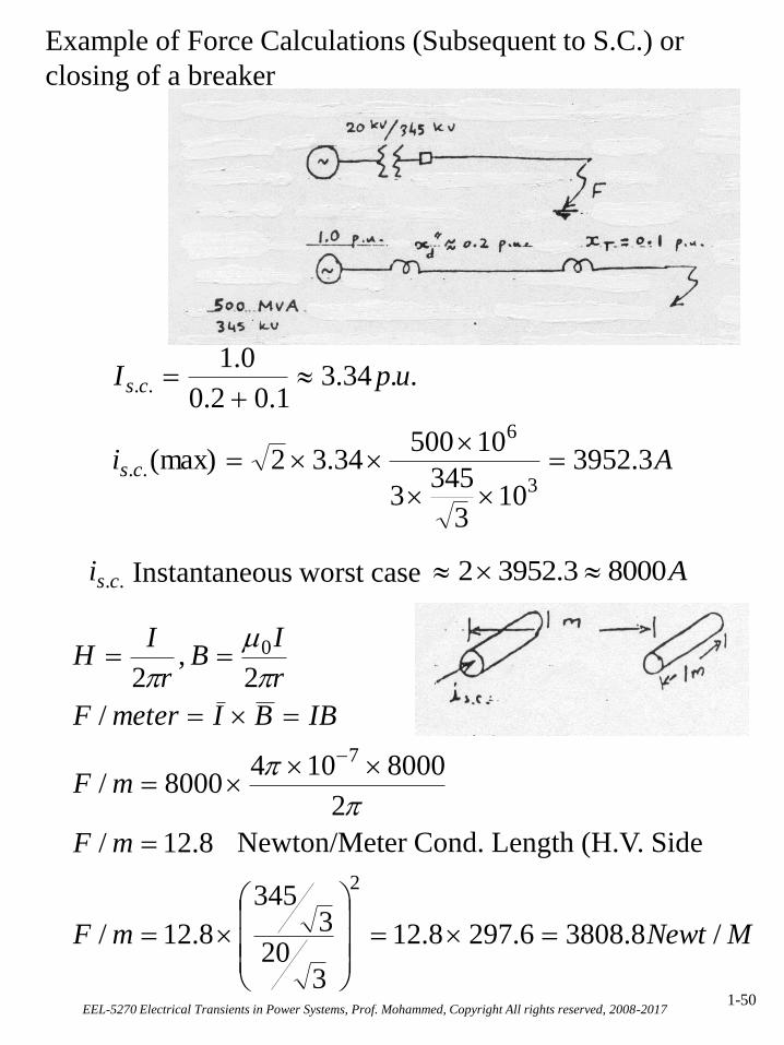
Example of Force Calculations (Subsequent to S.C.) or
closing of a breaker
..csi Instantaneous worst case A80003.39522
Ai
upI
cs
cs
3.3952
103
3453
1050034.32(max)
..34.31.02.0
0.1
3
6
..
..
MNewtmF
mF
mF
IBBImeterF
r
IB
r
IH
/8.38086.2978.12
320
3345
8.12/
8.12/
2
80001048000/
/
2,
2
2
7
0
Newton/Meter Cond. Length (H.V. Side

EEL-5270 Electrical Transients in Power Systems, Prof. Mohammed, Copyright All rights reserved, 2008-20171-51
Effect of Current Asymmetry on Recovery Voltage:
• When a circuit breaker is closed at random, it is
likely that the current during the transient period
will lack symmetry as shown below:
• In a three phase system, the voltages are 120 apart.
During the transient period, asymmetry will result in one
or more of the phases.
• The asymmetry will depend on the time in the cycle
at which the fault occurs.

EEL-5270 Electrical Transients in Power Systems, Prof. Mohammed, Copyright All rights reserved, 2008-20171-52
• The circuit breaker interrupt at an instant of the
cycle at which the current is zero.
• The recovery voltage will oscillate around the
instantaneous value of supply voltage.
• With asymmetrical fault current, the supply voltage
(system voltage) will no longer be at its peak. The
transient recovery voltage is not as high as was
shown earlier.
Effect of Current Asymmetry on Recovery Voltage

EEL-5270 Electrical Transients in Power Systems, Prof. Mohammed, Copyright All rights reserved, 2008-20171-53
Effect of Arc Resistance on Recovery Transient
•In cases where the arc voltage drop (across arc
resistance) cannot be ignored, from a quasi-quantitative
stand point, the arc drop is heavily resistive.
•This has the effect of bringing the current to be
interrupted no more in phase with the voltage.
•This has the effect of making the point of zero current
occur at point in the cycle at which the system voltage is
not at its peak. This has the effect of reducing the first
(sharpest) peak of the transient recovery voltage.
Effect of Arc Resistance on Recovery Voltage

EEL-5270 Electrical Transients in Power Systems, Prof. Mohammed, Copyright All rights reserved, 2008-20171-54
3 More Complex Recovery Transients
Consider an elementary power system which may
consist of a source and an unloaded transformer as
shown below:
Such a system can be represented from circuits point of
view as follows:
L1 and C1 represent the inductance and stray
capacitance on the source ride of the breaker. L2 and C2
may represent the inductance and stray capacitance of
the unloaded transformer.
When the circuit breaker opens in such a
power system it completely isolates the load side from
the supply side. After the instant of breaker operation,
the two halves of the system behave independently.

EEL-5270 Electrical Transients in Power Systems, Prof. Mohammed, Copyright All rights reserved, 2008-20171-55
What happens following such a switching operation?
(1) Before the breaker opens, the supply voltage will
divide in proportion to the inductances (capacitors
represent a high reactance path). The voltage across
the capacitors is:
(2) For all practical purposes, the transformer
inductance, L2, will be much larger than the source
inductance, L1. Hence, C1 and C2 have a voltage
vc(t), which is approximately equal to the full
supply voltage v(t).
(3) Following the current interruption, C2 will discharge
through L2 and a natural frequency f2.
Figure (b) on the next page shows that this transient
will be damped by circuit resistance.
)()(21
2 tvLL
Ltvc
222
2
1
CLf

EEL-5270 Electrical Transients in Power Systems, Prof. Mohammed, Copyright All rights reserved, 2008-20171-56
Double Frequency Recovery Voltage
(4) C1, on the source side, charged to a voltage
near source voltage level, will exhibit a
recovery transient voltage wave shape shown
on the next page.

EEL-5270 Electrical Transients in Power Systems, Prof. Mohammed, Copyright All rights reserved, 2008-20171-57
• In this case the natural frequency is smaller than the
case discussed earlier due to the initial charge on the
capacitor C1.
This is shown in figure (a) on the previous page.
(5) The voltage across the breaker is made of the
difference between vc1(t) and vc2(t). The result is
shown in Figure (c) on the previous page, which is
(wave(a)-wave(b))
The above case shows a recovery voltage wave with two
distinct frequencies f1 & f2.
111
2
1
CLf

EEL-5270 Electrical Transients in Power Systems, Prof. Mohammed, Copyright All rights reserved, 2008-20171-58
An even more complex case
Consider the following case which is encountered quite
frequently in the case of a circuit breaker clearing the fault
on the secondary side of a transformer as shown below:
Elementary Power System With Double Frequency
Recovery Voltage.
The equivalent circuit becomes as shown:
Equivalent Circuit of System
EEL-5270 Electrical Transients in Power Systems, Prof. Mohammed, Copyright All rights reserved, 2008-20171-59
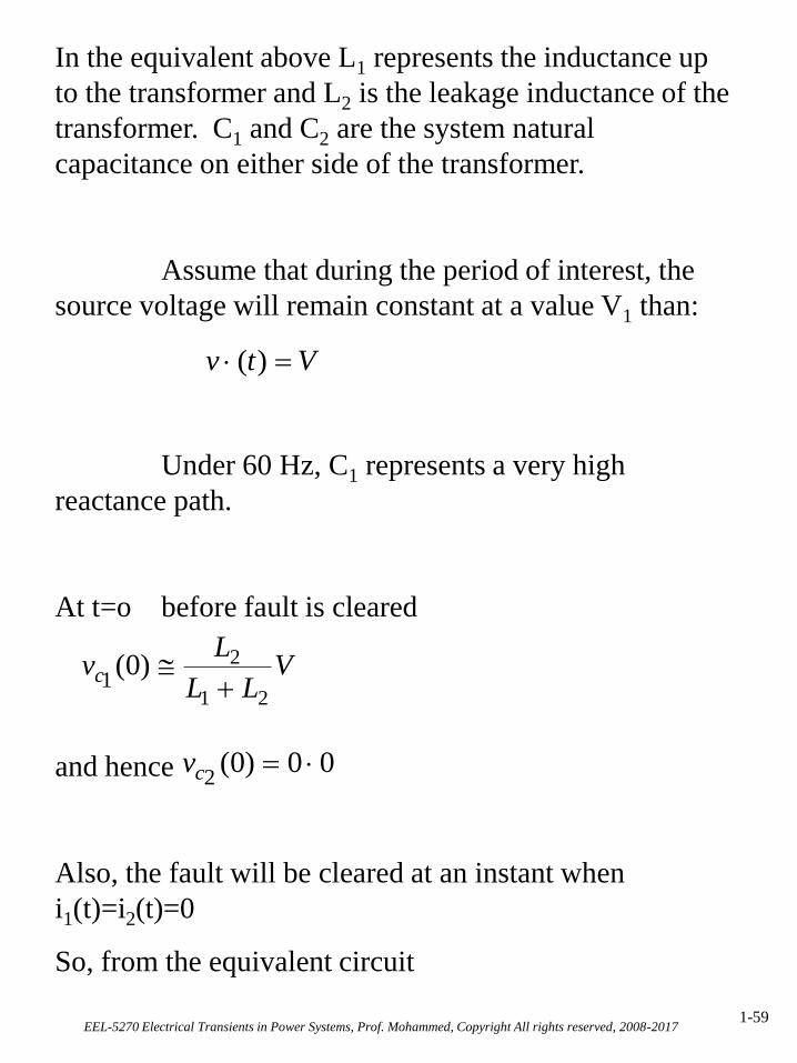
In the equivalent above L1 represents the inductance up
to the transformer and L2 is the leakage inductance of the
transformer. C1 and C2 are the system natural
capacitance on either side of the transformer.
Assume that during the period of interest, the
source voltage will remain constant at a value V1 than:
Under 60 Hz, C1 represents a very high
reactance path.
At t=o before fault is cleared
and hence
Also, the fault will be cleared at an instant when
i1(t)=i2(t)=0
So, from the equivalent circuit
Vtv )(
VLL
Lvc
21
2)0(1
00)0(2
cv

EEL-5270 Electrical Transients in Power Systems, Prof. Mohammed, Copyright All rights reserved, 2008-20171-60
dt
diL
dt
diLtvtv
dtic
vtv
dtiic
vdt
diLtvtv
c
tcc
tcc
22
11
202
2101
11
)()(
1)0()(
1)0()()(
2
22
11
0
Since v(t)=V, Laplace transform to the following:
)()(1
)(
)()(
)0()()0()()(
)(1
)(
)0()0(
)(1
)(1
)()(1)0(
)0()(
22
2
2
1
1
222
11
222
22221111
22
1121
11
1
211
1111
sVsVscLs
V
sLsI
ssvccsI
iLssILiLssILs
VsV
sIsc
sV
iLs
v
s
VsI
scsI
scsL
sIsIscs
viLssIL
s
V
cc
c
c
c
c
OR
and
and
and
0
0 0

EEL-5270 Electrical Transients in Power Systems, Prof. Mohammed, Copyright All rights reserved, 2008-20171-61
21211
2211
1
LLLcLB
cLcLA
Let and
,one has
))(())((
1)(
22
221
222
221
22 ss
Bs
sssAVsVc
Using the partial fraction technique one can show that
the inverse Laplace transform is:
tB
AV
tB
AVtvc
222
21
22
22
122
21
21
21
22
21
cos1
cos11
)(2
If , we can obtain a condition under which
the voltage vc2 which will show across the breaker
contacts might reach as high as (3V).
*The algebra gets rather involved quickly as more
circuit elements are added.
The propagation of surges on power T-Lines is
discussed next.
21