Embed Size (px)
Citation preview

Lecture Notes in Computer Science 2029Edited by G. Goos, J. Hartmanis and J. van Leeuwen

3BerlinHeidelbergNew YorkBarcelonaHong KongLondonMilanParisSingaporeTokyo
Heinrich Hussmann (Ed.)
Fundamental Approachesto Software Engineering
4th International Conference, FASE 2001Held as Part of the Joint European Conferenceson Theory and Practice of Software, ETAPS 2001Genova, Italy, April 2-6, 2001Proceedings
1 3
Series Editors
Gerhard Goos, Karlsruhe University, GermanyJuris Hartmanis, Cornell University, NY, USAJan van Leeuwen, Utrecht University, The Netherlands
Volume Editor
Heinrich HussmannTechnische Universitat DresdenInstitut fur Software- und Multimediatechnik01062 Dresden, GermanyE-mail:[email protected]
Cataloging-in-Publication Data applied for
Die Deutsche Bibliothek - CIP-Einheitsaufnahme
Fundamental approaches to software engineering : 4th internationalconference ; proceedings / FASE 2001, held as part of the JointEuropean Conferences on Theory and Practice of Software, ETAPS 2001,Berlin, Genova, Italy, April 2 - 6, 2001. Heinrich Hussmann (ed.). -Berlin ; Heidelberg ; New York ; Barcelona ; Hong Kong ; London ;Milan ; Paris ; Singapore ; Tokyo : Springer, 2001
(Lecture notes in computer science ; Vol. 2029)ISBN 3-540-41863-6
CR Subject Classification (1998): D.2, D.3, F.3
ISSN 0302-9743ISBN 3-540-41863-6 Springer-Verlag Berlin Heidelberg New York
This work is subject to copyright. All rights are reserved, whether the whole or part of the material isconcerned, specifically the rights of translation, reprinting, re-use of illustrations, recitation, broadcasting,reproduction on microfilms or in any other way, and storage in data banks. Duplication of this publicationor parts thereof is permitted only under the provisions of the German Copyright Law of September 9, 1965,in its current version, and permission for use must always be obtained from Springer-Verlag. Violations areliable for prosecution under the German Copyright Law.
Springer-Verlag Berlin Heidelberg New Yorka member of BertelsmannSpringer Science+Business Media GmbH
http://www.springer.de
© Springer-Verlag Berlin Heidelberg 2001Printed in Germany
Typesetting: Camera-ready by author, PTP Berlin, Stefan SossnaPrinted on acid-free paper SPIN 10782450 06/3142 5 4 3 2 1 0
Foreword
ETAPS 2001 is the fourth instance of the European Joint Conferences on Theoryand Practice of Software. ETAPS is an annual federated conference that wasestablished in 1998 by combining a number of existing and new conferences.This year it comprises five conferences (FOSSACS, FASE, ESOP, CC, TACAS),ten satellite workshops (CMCS, ETI Day, JOSES, LDTA, MMAABS, PFM,RelMiS, UNIGRA, WADT, WTUML), seven invited lectures, a debate, and tentutorials.
The events that comprise ETAPS address various aspects of the system de-velopment process, including specification, design, implementation, analysis andimprovement. The languages, methodologies and tools which support these ac-tivities are all well within its scope. Different blends of theory and practice arerepresented, with an inclination towards theory with a practical motivation onone hand and soundly-based practice on the other. Many of the issues involvedin software design apply to systems in general, including hardware systems, andthe emphasis on software is not intended to be exclusive.
ETAPS is a loose confederation in which each event retains its own identity,with a separate programme committee and independent proceedings. Its formatis open-ended, allowing it to grow and evolve as time goes by. Contributed talksand system demonstrations are in synchronized parallel sessions, with invitedlectures in plenary sessions. Two of the invited lectures are reserved for “unify-ing” talks on topics of interest to the whole range of ETAPS attendees. Theaim of cramming all this activity into a single one-week meeting is to create astrong magnet for academic and industrial researchers working on topics withinits scope, giving them the opportunity to learn about research in related areas,and thereby to foster new and existing links between work in areas that wereformerly addressed in separate meetings.
ETAPS 2001 is hosted by the Dipartimento di Informatica e Scienze dell’In-formazione (DISI) of the Universita di Genova and has been organized by thefollowing team:
Egidio Astesiano (General Chair)Eugenio Moggi (Organization Chair)Maura Cerioli (Satellite Events Chair)Gianna Reggio (Publicity Chair)Davide AnconaGiorgio DelzannoMaurizio Martelli
with the assistance of Convention Bureau Genova. Tutorials were organized byBernhard Rumpe (TU Munchen). Overall planning for ETAPS conferences is theresponsibility of the ETAPS Steering Committee, whose current membership is:
Egidio Astesiano (Genova), Ed Brinksma (Enschede), Pierpaolo Degano(Pisa), Hartmut Ehrig (Berlin), Jose Fiadeiro (Lisbon), Marie-ClaudeGaudel (Paris), Susanne Graf (Grenoble), Furio Honsell (Udine), Nigel
VI Foreword
Horspool (Victoria), Heinrich Hussmann (Dresden), Paul Klint (Amster-dam), Daniel Le Metayer (Rennes), Tom Maibaum (London), TizianaMargaria (Dortmund), Ugo Montanari (Pisa), Mogens Nielsen (Aarhus),Hanne Riis Nielson (Aarhus), Fernando Orejas (Barcelona), AndreasPodelski (Saarbrucken), David Sands (Goteborg), Don Sannella (Edin-burgh), Perdita Stevens (Edinburgh), Jerzy Tiuryn (Warsaw), DavidWatt (Glasgow), Herbert Weber (Berlin), Reinhard Wilhelm (Saar-brucken)
ETAPS 2001 is organized in cooperation with
the Association for Computing Machinerythe European Association for Programming Languages and Systemsthe European Association of Software Science and Technologythe European Association for Theoretical Computer Science
and has received generous sponsorship from:
ELSAGFondazione Cassa di Risparmio di Genova e ImperiaINDAM - Gruppo Nazionale per l’Informatica Matematica (GNIM)MarconiMicrosoft ResearchTelecom ItaliaTXT e-solutionsUniversita di Genova
I would like to express my sincere gratitude to all of these people and orga-nizations, the programme committee chairs and PC members of the ETAPSconferences, the organizers of the satellite events, the speakers themselves, andfinally Springer-Verlag for agreeing to publish the ETAPS proceedings.
Edinburgh, January 2001 Donald SannellaETAPS Steering Committee chairman
Preface
The Conference on Fundamental Approaches to Software Engineering (FASE),as its name indicates, is a pure software engineering conference. However, beingpart of the ETAPS event, it has a particular profile. It focuses on the appli-cation of theoretically founded techniques in practical software engineering andon approaches aiming towards a proper theory of software engineering. In thepast, FASE was sometimes mistaken for a Formal Methods conference. However,FASE covers Formal Methods as just a small part of its profile, and even thenit only covers application-oriented work on Formal Methods.
As the chairman of the program committee for FASE 2001, I am very happythat this instance of FASE fully coincides with this intended profile of the con-ference. I am also happy that FASE is an increasingly popular event, as can beseen from the increasing number of submissions. FASE 2001 attracted a recordnumber of 74 submissions. The scope of these submissions was very broad, co-vering many different areas of software engineering. The program committee hada difficult task in selecting just 22 papers out of the submissions. I am gratefulto my colleagues in the program committee that this process went smoothly andlead to a well-balanced program of very good scientific quality. The members ofthe FASE 2001 program committee were:
Egidio Astesiano (Universita di Genova, Italy)Michel Bidoit (ENS Cachan, France)Dan Craigen (ORA Ottawa, Canada)Jose Fiadeiro (Universidade de Lisboa, Portugal)Carlo Ghezzi (Politecnico di Milano, Italy)Heinrich Hussmann (Technische Universitat Dresden, Germany)Cliff Jones (University of Newcastle, UK)Tom Maibaum (King’s College London, UK)Bernhard Rumpe (Technische Universitat Munchen, Germany)Doug Smith (Kestrel Institute, USA)Martin Wirsing (Universitat Munchen, Germany)
When comparing the program with earlier FASE programs, it is obvious thatthe section on Formal Methods has decreased in size, but still keeps a promi-nent position, and puts strong emphasis on practical aspects, like real-worldcase studies. Some other software engineering topics, such as component-baseddevelopment, distributed systems, and testing, are included. The biggest groupof papers deals with a specification and modeling language which was not eventouched upon at the first FASE (1998) and just superficially covered at FASE1999 and FASE 2000. More than two thirds of the papers explicitly deal withthe Unified Modeling Language (UML), in particular with its theoretical foun-dations and possible extensions. Of course, it is quite controversial whether thislanguage is a scientific achievement in itself, since the evolution of UML is clearlydriven by industry and much of UML was defined essentially by establishing acompromise between divergent opinions. Nevertheless, the UML seems to haveestablished itself as one of the major transmission mechanisms between scientific
VIII Preface
research and practical application. It is a big step forward that nowadays manyfundamental research activities use the UML as a basis and therefore make theirresults easily accessible for practioners who are knowledgeable of UML. There-fore, I am also very happy with the high percentage of UML-related papers andhope that FASE (and ETAPS in general) will establish itself as a forum for thosepeople who are interested in a seriously scientific approach to UML.
It is also not just by coincidence that our invited speaker for FASE, BranSelic, comes from a company which is closely related to the invention of UML.His talk, which is summarized in this volume by a short abstract, points out animportant challenge to software engineering, that is the integration of physicaland quantitative aspects, besides the purely functional view which prevails today.
A scientific event like FASE is always the result of the co-operation of a largegroup of people. Therefore, I would like to thank the members of the programcommittee and the additional referees, as listed below, for the enormous amountof work they invested in the selection process. Special thanks go to AnsgarKonermann for his reliable support, in particular by providing and maintainingthe Web site on which the virtual program committee meeting was carried out.Many thanks also to Don Sannella, Egidio Astesiano, and the whole ETAPS2001 team for providing the well-organized framework for this conference.
January 2001 Heinrich HussmannFASE 2001 Program Committee chairman

Referees
R. AmadioL. AndradeH. BaumeisterM. BeckerD. BertB. BlancM. CerioliD. ClarkT. ClarkP. R. D’ArgenioA. De LuciaB. DemuthTh. DimitrakosC. DuarteL. ErringtonM. FischerS. FitzpatrickC. FoxF. FunfstuckJ.-M. GeibJ. Goubault-LarrecqA. HaebererR. HennickerS. KentA. KnappP. KosiuczenkoS. Kromodimoeljo
F.-U. KumichelK. LanoA. LopesP. MagilloB. MarreS. MerzB. MollerT. NipkowI. NunesL. PetrucciA. PretschnerG. ReggioB. ReusJ.-C. ReynaudM. SaaltinkR. SandnerPh. SchnoebelenJ. ThierryA. ThomasV. VasconcelosF. VoisinM. WermelingerS. WestfoldG. WimmelJ. ZappeE. Zucca
Table of Contents
Invited Paper
Physical Programming: Beyond Mere Logic (Invited Talk) . . . . . . . . . . . . . . . 1Bran Selic (Rational Software Inc., Canada)
Metamodelling
Metamodelling and Conformance Checking with PVS . . . . . . . . . . . . . . . . . . . 2Richard F. Paige, Jonathan S. Ostroff (York University, Toronto)
The Metamodelling Language Calculus: Foundation Semantics for UML . . 17Tony Clark (King’s College London), Andy Evans (University of York),Stuart Kent (University of Kent at Canterbury)
Distributed Components
Compositional Checking of Communication among Observers . . . . . . . . . . . . 32Ralf Pinger, Hans-Dieter Ehrich (Technische Universitat Braunschweig)
Combining Independent Specifications . . . . . . . . . . . . . . . . . . . . . . . . . . . . . . . . 45Joy N. Reed (Oxford Brookes University), Jane E. Sinclair(University of Warwick)
Proving Deadlock Freedom in Component-Based Programming . . . . . . . . . . 60Paola Inverardi (Universita dell’ Aquila), Sebastian Uchitel(Imperial College)
UML
A Real-Time Execution Semantics for UML Activity Diagrams . . . . . . . . . . 76Rik Eshuis, Roel Wieringa (University of Twente)
A CSP View on UML-RT Structure Diagrams . . . . . . . . . . . . . . . . . . . . . . . . . 91Clemens Fischer, Ernst-Rudiger Olderog, Heike Wehrheim(Universitat Oldenburg)
Strengthening UML Collaboration Diagrams by State Transformations . . . 109Reiko Heckel, Stefan Sauer (University of Paderborn)
Specification of Mixed Systems in Korrigan with the Support of aUML-Inspired Graphical Notation . . . . . . . . . . . . . . . . . . . . . . . . . . . . . . . . . . . . 124
Christine Choppy (Universite Paris XIII), Pascal Poizat,Jean-Claude Royer (Universite de Nantes)
XII Table of Contents
On Use Cases and Their Relationships in the Unified Modelling-Language . 140Perdita Stevens (University of Edinburgh)
On the Importance of Inter-scenario Relationships in Hierarchical StateMachine Design . . . . . . . . . . . . . . . . . . . . . . . . . . . . . . . . . . . . . . . . . . . . . . . . . . . . 156
Francis Bordeleau, Jean-Pierre Corriveau(Carleton University, Ottawa)
Towards a Rigorous Semantics of UML SupportingIts Multiview Approach . . . . . . . . . . . . . . . . . . . . . . . . . . . . . . . . . . . . . . . . . . . . . 171
Gianna Reggio, Maura Cerioli, Egidio Astesiano(Universita di Genova)
Towards Development of Secure Systems Using UMLsec . . . . . . . . . . . . . . . . 187Jan Jurjens (University of Oxford)
Testing
Grammar Testing . . . . . . . . . . . . . . . . . . . . . . . . . . . . . . . . . . . . . . . . . . . . . . . . . . 201Ralf Lammel (CWI Amsterdam)
Debugging via Run-Time Type Checking . . . . . . . . . . . . . . . . . . . . . . . . . . . . . 217Alexey Loginov, Suan Hsi Yong, Susan Horwitz, Thomas Reps(University of Wisconsin-Madison)
Library-Based Design and Consistency Checking of System-LevelIndustrial Test Cases . . . . . . . . . . . . . . . . . . . . . . . . . . . . . . . . . . . . . . . . . . . . . . . 233
Oliver Niese (METAFrame Technologies, Dortmund),Bernhard Steffen (University of Dortmund), Tiziana Margaria (ME-TAFrame Technologies, Dortmund), Andreas Hagerer (METAFrameTechnologies, Dortmund), Georg Brune, Hans-Dieter Ide (Siemens,Witten)
Demonstration of an Automated Integrated Testing Environment for CTISystems . . . . . . . . . . . . . . . . . . . . . . . . . . . . . . . . . . . . . . . . . . . . . . . . . . . . . . . . . . 249
Oliver Niese, Markus Nagelmann, Andreas Hagerer (METAFrameTechnologies, Dortmund), Klaus Kolodziejczyk-Strunck (HeraKom,Essen), Werner Goerigk, Andrei Erochok, Bernhard Hammelmann(Siemens, Witten)
Formal Methods
Semantics of Architectural Specifications in CASL . . . . . . . . . . . . . . . . . . . . . 253Lutz Schroder, Till Mossakowski (Bremen University), Andrzej Tarlecki(Warsaw University), Bartek Klin (BRICS, Aarhus), Piotr Hoffman(Warsaw University)
Table of Contents XIII
Extending Development Graphs with Hiding . . . . . . . . . . . . . . . . . . . . . . . . . . 269Till Mossakowski (University of Bremen), Serge Autexier (SaarlandUniversity), Dieter Hutter (DKFI, Saarbrucken)
A Logic for the Java Modeling Language JML . . . . . . . . . . . . . . . . . . . . . . . . . 284Bart Jacobs, Erik Poll (University Nijmegen)
A Hoare Calculus for Verifying Java Realizations ofOCL-Constrained Design Models . . . . . . . . . . . . . . . . . . . . . . . . . . . . . . . . . . . . . 300
Bernhard Reus (University of Sussex at Brighton), Martin Wirsing,Rolf Hennicker (Ludwig-Maximilians-Universitat Munchen)
Case Studies
A Formal Object-Oriented Analysis for Software Reliability: Design forVerification . . . . . . . . . . . . . . . . . . . . . . . . . . . . . . . . . . . . . . . . . . . . . . . . . . . . . . . 318
Natasha Sharygina (Bell Laboratories), James C. Browne (Universityof Texas at Austin), Robert P. Kurshan (Bell Laboratories)
Specification and Analysis of the AER/NCA Active Network ProtocolSuite in Real-Time Maude . . . . . . . . . . . . . . . . . . . . . . . . . . . . . . . . . . . . . . . . . . 333
Peter C. Olveczky (SRI, Menlo Park and University of Oslo),Mark Keaton (Litton-TASC, Reading), Jose Meseguer(SRI, Menlo Park), Carolyn Talcott (Stanford University), Steve Zabele(Litton-TASC, Reading)
Author Index . . . . . . . . . . . . . . . . . . . . . . . . . . . . . . . . . . . . . . . . . . . . . . . . . . . 349
Physical Programming: Beyond Mere Logic(Invited Talk)
Bran Selic
Rational Software Inc., [email protected]
Abstract. Plato believed in a “pure” reality, where ideas existed intheir perfection into eternity. What we perceive as reality, he claimed, ismerely a flawed shadow of this ideal world. Many mathematicians findthis view appealing since it is precisely this universe of ideas that isthe subject of their exploration and discovery. The computer, and morespecifically, software, seem perfectly suited to this viewpoint. They al-low us to create our own reality, one in which we can simply ignore theunderlying physics, forget the tyranny of inertial mass, the drudgery ofdealing with machinery that leaks or parts that do not quite fit. But,can we? Even in the ideal world with infinite resources, we have discov-ered that there are limits to computability. However, the situation withcomputers and software is much more dire than mere limits on whatcan be computed. As computers today play an indispensable part of ourdaily lives we find that more and more of the software in them needs tointeract with the physical world. Unfortunately, the current generationof software technologies and practices are constructed around the oldPlatonic ideal. Standard wisdom in designing software encourages us toignore the underlying technological platform D after all, it is likely tochange in a few years anyway D and focus exclusively on the program“logic”. However, when physical distribution enters the picture, we findthat mundane things such as transmission delays or component failuresmay have a major impact on that logic. The need to deal with this kindof raw physical “stuff” out of which the software is constructed has beenrelegated to highly specialised areas, such as real-time programming. Theresult is that we are singularly unprepared for the coming new generationof Internet-based software. Even languages that were nominally designedfor this environment, such as Java, are lacking in this regard. For exam-ple, it has no facility to formally express that a communication betweentwo remote parts must be performed within a specified time interval. Inthis talk, we first justify the need to account for the physical aspectswhen doing software design. We then describe a conceptual frameworkthat allows us to formally specify and reason about such aspects. In par-ticular, it requires that we significantly expand the concept of type ascurrently defined in software theory.
References
1. B. Selic, “A generic framework for modeling resources with UML”, IEEE Computer,June 2000.
H. Hussmann (Ed.): FASE 2001, LNCS 2029, p. 1, 2001.c© Springer-Verlag Berlin Heidelberg 2001
Metamodelling and Conformance Checking with PVS
Richard F. Paige and Jonathan S. Ostroff
Department of Computer Science, York University,Toronto, Ontario M3J 1P3, Canada. {paige,jonathan}@cs.yorku.ca
Abstract. A metamodel expresses the syntactic well-formedness constraints thatall models written using the notation of a modelling language must obey. Weformally capture the metamodel for an industrial-strength object-oriented mod-elling language, BON, using the PVS specification language. We discuss how thePVS system helped in debugging the metamodel, and show how to use the PVStheorem prover for conformance checking of models against the metamodel. Weconsider some of the benefits of using PVS’s specification language, and discusssome lessons learned about formally specifying metamodels.
1 Introduction
Modelling languages such as UML [2], BON [7], and others have been used to capturerequirements, describe designs, and to document software systems. Such languages aresupported by tools, which aid in the construction of models, the generation of code frommodels, and the reverse engineering of models from code.
A modelling language consists of two parts: a notation, used to write models; anda metamodel, which expresses the syntactic well-formedness constraints that all validmodels written using the notation must obey [2]. Metamodels serve several purposesthat may be of interest to different modelling language users.
– Modellers: metamodels should be easy to understand by modellers. Thus, metamod-els should be expressed so that their fundamental details can be easily explained tomodellers, without requiring them to understand much formalism.
– Tool Builders: metamodels provide specifications for tool builders who are con-structing applications to support the modelling language. Thus, metamodels shouldbe precise and not open to misinterpretation.
– Modelling Language Designers: language designers have the responsibility toensure that metamodels are consistent. Thus, metamodels should be expressed in aformalism so that automated reasoning about it can be carried out.
Different modelling language users have different goals, and therefore a metamodelmust possess a collection of different characteristics. Metamodels must be understand-able, to assist in the use of the language and its supporting tools. They should be unam-biguous and not open to misinterpretation. A metamodel should be expressed in a formamenable to tool-based analysis, e.g., for consistency checking. And, to best deal withcomplexity and issues of scale, a metamodel should be well-structured.
In this paper, we present a formal specification of the metamodel of the BON object-oriented (OO) modelling language [7], written using the PVS specification language [3].
H. Hussmann (Ed.): FASE 2001, LNCS 2029, pp. 2–16, 2001.c© Springer-Verlag Berlin Heidelberg 2001
Metamodelling and Conformance Checking with PVS 3
The PVS language has been designed for automated analysis, using the PVS system,which provides a theorem prover and typechecker. We construct the formal specificationin two steps. We first specify the BON metamodel informally, using BON itself. In thismanner, we use BON’s structuring facilities to help understand the key abstractions usedin the metamodel and their constraints, before writing a formal specification. From theBON version of the metamodel, we then construct a set of PVS theories that capture themetamodel. The PVS theories can then be used, in conjunction with the PVS system, toanalyze and answer questions about the metamodel.
The specific contributions of this paper are as follows.
1. A formal specification of the syntactic well-formedness constraints for BON inthe PVS language. To our knowledge, this is the first formal specification of thefull metamodel of an OO modelling language in a form that is also amenable toautomated analysis.
2. A description of how the PVS language can be used for metamodelling, and howthe PVS system can be used to help debug and verify the metamodel.
3. Examples of how the PVS system can be used to reason about the metamodel. As aspecific example, we show how to prove that BON models satisfy the metamodel.
2 An Overview of BON
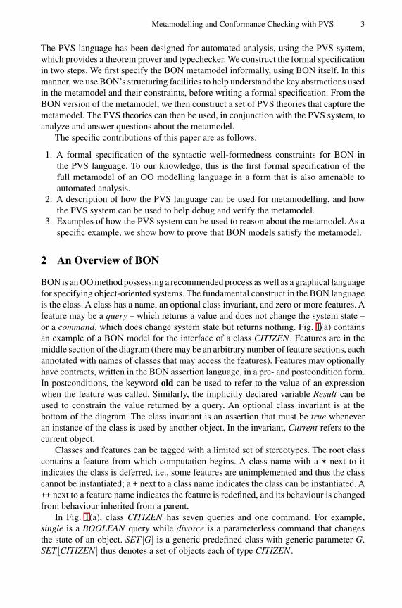
BON is an OO method possessing a recommended process as well as a graphical languagefor specifying object-oriented systems. The fundamental construct in the BON languageis the class. A class has a name, an optional class invariant, and zero or more features. Afeature may be a query – which returns a value and does not change the system state –or a command, which does change system state but returns nothing. Fig. 1(a) containsan example of a BON model for the interface of a class CITIZEN . Features are in themiddle section of the diagram (there may be an arbitrary number of feature sections, eachannotated with names of classes that may access the features). Features may optionallyhave contracts, written in the BON assertion language, in a pre- and postcondition form.In postconditions, the keyword old can be used to refer to the value of an expressionwhen the feature was called. Similarly, the implicitly declared variable Result can beused to constrain the value returned by a query. An optional class invariant is at thebottom of the diagram. The class invariant is an assertion that must be true wheneveran instance of the class is used by another object. In the invariant, Current refers to thecurrent object.
Classes and features can be tagged with a limited set of stereotypes. The root classcontains a feature from which computation begins. A class name with a * next to itindicates the class is deferred, i.e., some features are unimplemented and thus the classcannot be instantiated; a + next to a class name indicates the class can be instantiated. A++ next to a feature name indicates the feature is redefined, and its behaviour is changedfrom behaviour inherited from a parent.
In Fig. 1(a), class CITIZEN has seven queries and one command. For example,single is a BOOLEAN query while divorce is a parameterless command that changesthe state of an object. SET [G] is a generic predefined class with generic parameter G.SET [CITIZEN ] thus denotes a set of objects each of type CITIZEN .
4 R.F. Paige and J.S. Ostroff
spouse.spouse=Current;
p=Current
spouse : CITIZENchildren, parents : SET[CITIZEN]
single : BOOLEAN
Result <-> (spouse=Void)!
divorce
? single
name, sex, age : VALUE
not
single and (old spouse).single
single orparents.count=2;
children" c $ p c.parents
!
CITIZEN
invariant
∈∈
(a) Citizen interface
SUPPLIER2
SUPPLIER1
CHILD
ANCESTOR
(b) BON relationships
Fig. 1. BON syntax for interfaces and relationships.
BON models usually consist of classes organized in clusters (drawn as dashedrounded rectangles – see Section 3), which interact via two kinds of relationships.
– Inheritance: Inheritance defines a subtype relationship between child and one ormore parents. The inheritance relationship is drawn between classes CHILD andANCESTOR in Fig. 1(b), with the arrow directed from the child to the parent class.In this figure, classes have been drawn in their compressed form, as ellipses, withinterface details hidden.
– Client-supplier: there are two client-supplier relationships, association and aggre-gation. Both relationships are directed from a client class to a supplier class. Withassociation the client class has a reference to an object of the supplier class. Withaggregation the client class contains an object of the supplier class. The aggregationrelationship is drawn between classes CHILD and SUPPLIER2 in Fig. 1(b), whereasan association is drawn from ANCESTOR to class SUPPLIER1.
3 BON Specification of the Metamodel
We now present an informal specification of the BON metamodel, written in BON itself.This description is aimed at promoting an understanding of the fundamental abstractionsand relationships that BON models use. We use BON to informally capture the meta-model, and the BON description will be used to help produce a formal specification ofthe metamodel in the PVS language.
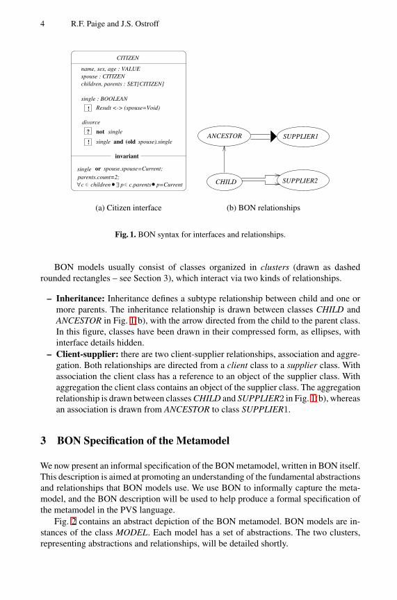
Fig. 2 contains an abstract depiction of the BON metamodel. BON models are in-stances of the class MODEL. Each model has a set of abstractions. The two clusters,representing abstractions and relationships, will be detailed shortly.
Metamodelling and Conformance Checking with PVS 5
ABSTRACTIONS RELATIONSHIPS
MODELabs: SET[..]
Fig. 2. The BON metamodel, abstract architecture.
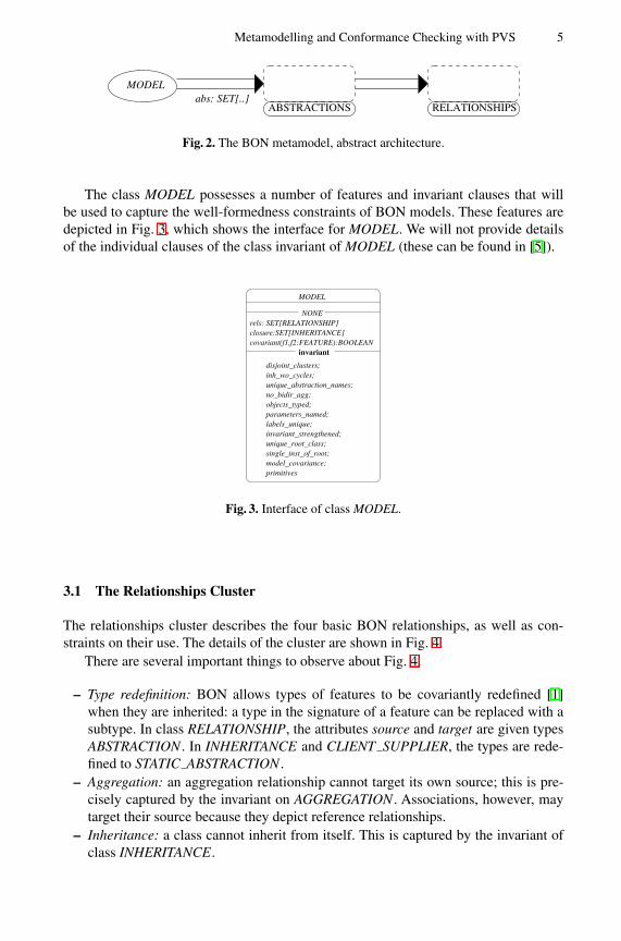
The class MODEL possesses a number of features and invariant clauses that willbe used to capture the well-formedness constraints of BON models. These features aredepicted in Fig. 3, which shows the interface for MODEL. We will not provide detailsof the individual clauses of the class invariant of MODEL (these can be found in [5]).
invariant
disjoint_clusters;
unique_abstraction_names;no_bidir_agg;objects_typed;parameters_named;labels_unique;
covariant(f1,f2:FEATURE):BOOLEANclosure:SET[INHERITANCE]
inh_wo_cycles;
invariant_strengthened;unique_root_class;single_inst_of_root;
rels: SET[RELATIONSHIP]NONE
MODEL
primitivesmodel_covariance;
Fig. 3. Interface of class MODEL.
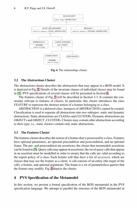
3.1 The Relationships Cluster
The relationships cluster describes the four basic BON relationships, as well as con-straints on their use. The details of the cluster are shown in Fig. 4.
There are several important things to observe about Fig. 4.
– Type redefinition: BON allows types of features to be covariantly redefined [1]when they are inherited: a type in the signature of a feature can be replaced with asubtype. In class RELATIONSHIP, the attributes source and target are given typesABSTRACTION . In INHERITANCE and CLIENT SUPPLIER, the types are rede-fined to STATIC ABSTRACTION .
– Aggregation: an aggregation relationship cannot target its own source; this is pre-cisely captured by the invariant on AGGREGATION . Associations, however, maytarget their source because they depict reference relationships.
– Inheritance: a class cannot inherit from itself. This is captured by the invariant ofclass INHERITANCE.
6 R.F. Paige and J.S. Ostroff
STATIC_RELATIONSHIP*
CLIENT_SUPPLIER*
label: STRINGinvariantsource /= target
invariantsource /= target
source++, target++: STATIC_ABSTRACTION source++, target++: DYNAMIC_ABSTRACTION
RELATIONSHIP*
source, target: ABSTRACTION
MESSAGE+
INHERITANCE+
AGGREGATION+ ASSOCIATION+
Fig. 4. The relationships cluster.
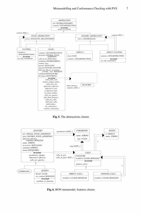
3.2 The Abstractions Cluster
The abstractions cluster describes the abstractions that may appear in a BON model. Itis depicted in Fig. 5. Details of the invariant clauses of individual classes may be foundin [5]; PVS specifications of several clauses will be presented in Section 4.
The features cluster of Fig. 5 will be described in Section 3.3. It contains the con-straints relevant to features of classes. In particular, this cluster introduces the classFEATURE to represent the abstract notion of a feature belonging to a class.
ABSTRACTION is a deferred class: instances of ABSTRACTIONs cannot be created.Classification is used to separate all abstractions into two subtypes: static and dynamicabstractions. Static abstractions are CLASSes and CLUSTERs. Dynamic abstractions areOBJECTs and OBJECT CLUSTERs. Clusters may contain other abstractions accordingto their type, i.e., static clusters contain only static abstractions.
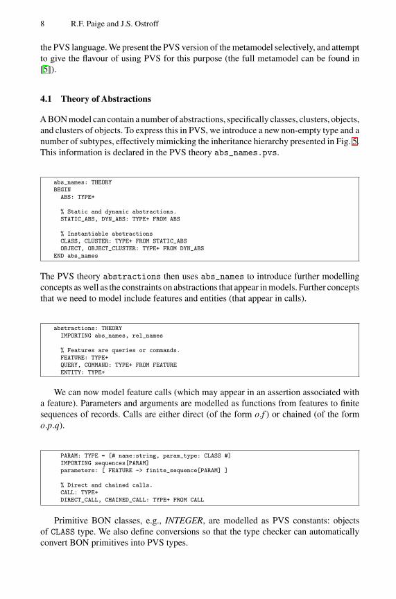
3.3 The Features Cluster
The features cluster describes the notion of a feature that is possessed by a class. Featureshave optional parameters, an optional precondition and postcondition, and an optionalframe. The pre- and postcondition are assertions; the cluster that metamodels assertionscan be found in [5]. Query calls may appear in assertions; the set of query calls that appearin an assertion must be modelled in order to ensure that the calls are valid according tothe export policy of a class. Each feature will thus have a list of accessors, which areclasses that may use the feature as a client. A call consists of an entity (the target of thecall), a feature, and optional arguments. The frame is a set of parameterless queries thatthe feature may modify. Fig. 6 depicts the cluster.
4 PVS Specification of the Metamodel
In this section, we present a formal specification of the BON metamodel in the PVSspecification language. We attempt to parallel the structure of the BON metamodel in
Metamodelling and Conformance Checking with PVS 7
contains+:SET[ABSTRACTION]
contains+:SET[ABSTRACTION]class:CLASS
contains+:SET[ABSTRACTION]
invariantinvariant
contents:SET[..]
DYNAMIC_ABSTRACTION*
CLUSTER+
OBJECT+ OBJECT_CLUSTER+
ABSTRACTION*
invariantsource_is_current
STATIC_ABSTRACTION* contents:SET[..]
rels++:SET[MESSAGE]
contains*:SET[ABSTRACTION]rels: SET[RELATIONSHIP]
rels++:SET[STATIC_RELATIONSHIP]
no_self_containmentno_self_containment
FEATURESclient_features,features: SET[..]
add_client_features;calls_are_queries;no_name_clashes;is_deferred_class;deferred /= root;
deferred /= effective;valid_class_inv;
feature_unique_names;valid_static_rels;
invariantall_names:SET[STRING]redefined:SET[FEATURE]
external, root : BOOLEANdeferred, effective, persistent,super(f:FEATURE):FEATUREparents: SET[CLASS]rename_classrenamings:SET[RENAMING]calls_in_inv:SET[CALL]
ASSERTIONinvariant: DOUBLE_STATE_contains+:SET[ABSTRACTION]
valid_pre_calls;
CLASS+
valid_post_calls;valid_frames;
inv_consistency;contract_consistency;
Fig. 5. The abstractions cluster.
PARAMETER
name: STRING
type: CLASS
parameters:LIST[..]
calls_in_post: SET[..]calls_in_pre,
args:LIST[..]
FEATURE*
pre: SINGLE_STATE_ASSERTIONpost: DOUBLE_STATE_ASSERTION
o: OBJECTname: STRING
e
deferred /= effective;parameters_unique;
calls_are_queries;
invariantframe:SET[QUERY]rename(s:STRING)accessors: SET[CLASS]name: STRING
deferred, effective,redefined: BOOLEAN
DIRECT_CALL+ CHAINED_CALL+
isvalid+(c:CLASS):BOOLEAN isvalid+(c:CLASS):BOOLEAN
v
ENTITY
COMMAND+Result: CLASSno_contract:BOOLEAN
attribute_or_functioninvariant
QUERY+
f:FEATUREisvalid*(c:CLASS):BOOLEAN
invariant
CALL*
feature_exists
Fig. 6. BON metamodel, features cluster.
8 R.F. Paige and J.S. Ostroff
the PVS language. We present the PVS version of the metamodel selectively, and attemptto give the flavour of using PVS for this purpose (the full metamodel can be found in[5]).
4.1 Theory of Abstractions
A BON model can contain a number of abstractions, specifically classes, clusters, objects,and clusters of objects. To express this in PVS, we introduce a new non-empty type and anumber of subtypes, effectively mimicking the inheritance hierarchy presented in Fig. 5.This information is declared in the PVS theory abs_names.pvs.
abs_names: THEORYBEGIN
ABS: TYPE+
% Static and dynamic abstractions.STATIC_ABS, DYN_ABS: TYPE+ FROM ABS
% Instantiable abstractionsCLASS, CLUSTER: TYPE+ FROM STATIC_ABSOBJECT, OBJECT_CLUSTER: TYPE+ FROM DYN_ABS
END abs_names
The PVS theory abstractions then uses abs_names to introduce further modellingconcepts as well as the constraints on abstractions that appear in models. Further conceptsthat we need to model include features and entities (that appear in calls).
abstractions: THEORYIMPORTING abs_names, rel_names
% Features are queries or commands.FEATURE: TYPE+QUERY, COMMAND: TYPE+ FROM FEATUREENTITY: TYPE+
We can now model feature calls (which may appear in an assertion associated witha feature). Parameters and arguments are modelled as functions from features to finitesequences of records. Calls are either direct (of the form o.f ) or chained (of the formo.p.q).
PARAM: TYPE = [# name:string, param_type: CLASS #]IMPORTING sequences[PARAM]parameters: [ FEATURE -> finite_sequence[PARAM] ]
% Direct and chained calls.CALL: TYPE+DIRECT_CALL, CHAINED_CALL: TYPE+ FROM CALL
Primitive BON classes, e.g., INTEGER, are modelled as PVS constants: objectsof CLASS type. We also define conversions so that the type checker can automaticallyconvert BON primitives into PVS types.
Metamodelling and Conformance Checking with PVS 9
bool_object, int_object, string_object, real_object, any_object: CLASS
% Example conversions that the PVS typechecker can automatically apply.interp_bool: [ bool_object -> bool ]interp_int: [ int_object -> int ]CONVERSION interp_bool, interp_int
We must now describe constraints on abstractions. In the BON version of the meta-model, these took the form of features and class invariants. In PVS, the well-formednessconstraints will appear as functions, predicate subtypes, and axioms. We start by defininga number of functions that will later be used to constrain the model.
% The class that an object belongs to, and the features of a class.object_class: [ OBJECT -> CLASS ]class_features: [ CLASS -> set[FEATURE] ]
% The contents of a cluster. Note that clusters may be nested.cluster_contents: [ CLUSTER -> set[STATIC_ABS] ]
A number of constraints will have to be written on features. To accomplish this, weintroduce a number of functions that will let us acquire information about a feature, suchas its properties, precondition, and postcondition.
feature_pre, feature_post: [ FEATURE -> bool ]
% Properties of a feature.deferred_feature, effective_feature, redefined_feature: [ FEATURE -> bool ]
% The set of classes that can legally access a feature.accessors: [ FEATURE -> set[CLASS] ]
We need to be able to capture the concept of a legal set of calls. Consider an assertionin BON, e.g., a precondition. Such an assertion may call a query if the class owning thequery has given permission to do so. To accomplish this, we introduce functions thatgive us all the calls associated with a precondition, postcondition, and invariant.
calls_in_pre, calls_in_post: [ FEATURE -> set[CALL] ]calls_in_inv: [ CLASS -> set[CALL] ]
We now provide examples of axioms, which define the constraints on BON models.The first example ensures that all features of a class have unique names (BON does notpermit overloading based on feature names or signatures).
feature_unique_names: AXIOM(FORALL (c:CLASS): (FORALL (f1,f2:FEATURE):
(member(f1,class_features(c)) AND member(f2,class_features(c)))IMPLIES (feature_name(f1) = feature_name(f2)) IMPLIES f1=f2))
A further axiom ensures that clusters do not contain themselves.
no_self_containment_cl: AXIOM(FORALL (cl:CLUSTER): not member(cl,cluster_contents(cl)))
10 R.F. Paige and J.S. Ostroff
Here is an example of specifying that an assertion is valid according to the exportpolicy used in a model. The axiom valid_precondition_calls ensures that: (a) allcalls in a precondition are legal (according to the accessor list for each feature); and (b)all calls in the precondition are queries.
valid_precondition_calls: AXIOM(FORALL (c:CLASS): (FORALL (f:FEATURE): member(f, class_features(c)) IMPLIES
(FORALL (call:CALL): member(call, calls_in_pre(f)) IMPLIESQUERY_pred(f(call)) AND call_isvalid(f(call)))))
Classes may possess stereotypes, e.g., they may be deferred or effective. Here is anexample, showing that a class cannot be both deferred and effective.
deferred_effective_ax: AXIOM(FORALL (c:CLASS): (NOT (deferred_class(c) IFF effective_class(c))))
4.2 Theory of Relationships
The theory of relationships defines the three basic relationships and the well-formednessconstraints that exist in BON. To express the relationships in PVS, we introduce a newnon-empty type and a number of subtypes.As with abstractions, we mimic the inheritancehierarchy that was presented in Fig. 4.
rel_names: THEORYBEGIN
% The abstract concept of a relationship.REL: TYPE+
% Instantiable relationships.INH, C_S, MESSAGE: TYPE+ FROM RELAGG, ASSOC: TYPE+ FROM C_S
END rel_names
The rel_names theory is then used by the relationships theory. In BON, allrelationships are directed (or targetted). Thus, each relationship has a source and atarget, and these concepts are modelled using PVS functions.
relationships: THEORYBEGIN
IMPORTING rel_names, abstractions
% Examples of the source and target of a relationship.inh_source, inh_target: [ INH -> STATIC_ABS ]cs_source, cs_target: [ C_S -> STATIC_ABS ]
Now we can express constraints on the functions.We give one example of relationshipconstraints: that inheritance relationships cannot be self-targetted.
% Inheritance relationships cannot be directed from an abstraction to itself.inh_ax: AXIOM (FORALL (i:INH): NOT (inh_source(i)=inh_target(i)))
Metamodelling and Conformance Checking with PVS 11
The theory of relationships is quite simple, because many of the constraints on theuse of relationships are global constraints that can only be specified when it is possibleto discuss all abstractions in a model. Thus, further relationship constraints will be addedin the next section, where we describe constraints on models themselves.
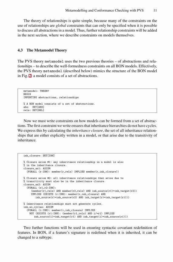
4.3 The Metamodel Theory
The PVS theory metamodel uses the two previous theories – of abstractions and rela-tionships – to describe the well-formedness constraints on all BON models. Effectively,the PVS theory metamodel (described below) mimics the structure of the BON modelin Fig. 2: a model consists of a set of abstractions.
metamodel: THEORYBEGINIMPORTING abstractions, relationships
% A BON model consists of a set of abstractions.abs: SET[ABS]rels: SET[REL]
Now we must write constraints on how models can be formed from a set of abstrac-tions. The first constraint we write ensures that inheritance hierarchies do not have cycles.We express this by calculating the inheritance closure, the set of all inheritance relation-ships that are either explicitly written in a model, or that arise due to the transitivity ofinheritance.
inh_closure: SET[INH]
% Closure axiom #1: any inheritance relationship in a model is also% in the inheritance closure.closure_ax1: AXIOM
(FORALL (r:INH): member(r,rels) IMPLIES member(r,inh_closure))
% Closure axiom #2: all inheritance relationships that arise due to% transitivity must also be in the inheritance closure.closure_ax2: AXIOM
(FORALL (r1,r2:INH):(member(r1,rels) AND member(r2,rels) AND inh_source(r1)=inh_target(r2))IMPLIES (EXISTS (r:INH): member(r,inh_closure) AND
inh_source(r)=inh_source(r2) AND inh_target(r)=inh_target(r1)))
% Inheritance relationships must not generate cycles.inh_wo_cycles: AXIOM
(FORALL (i:INH): member(i,inh_closure) IMPLIESNOT (EXISTS (r1:INH): (member(r1,rels) AND i/=r1) IMPLIES
inh_source(i)=inh_target(r1) AND inh_target(i)=inh_source(r1)))
Two further functions will be used in ensuring syntactic covariant redefinition offeatures. In BON, if a feature’s signature is redefined when it is inherited, it can bechanged to a subtype.
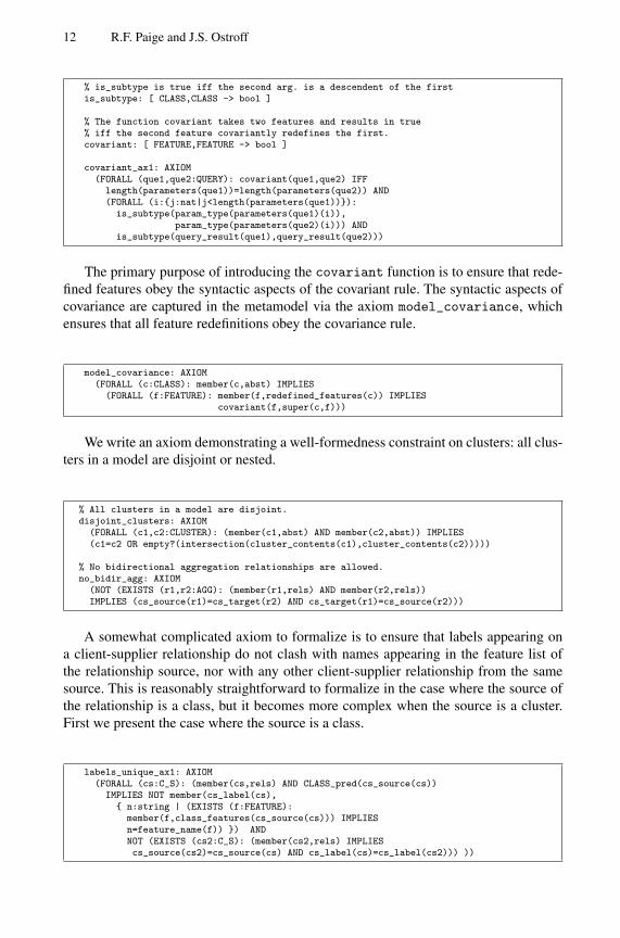
12 R.F. Paige and J.S. Ostroff
% is_subtype is true iff the second arg. is a descendent of the firstis_subtype: [ CLASS,CLASS -> bool ]
% The function covariant takes two features and results in true% iff the second feature covariantly redefines the first.covariant: [ FEATURE,FEATURE -> bool ]
covariant_ax1: AXIOM(FORALL (que1,que2:QUERY): covariant(que1,que2) IFF
length(parameters(que1))=length(parameters(que2)) AND(FORALL (i:{j:nat|j<length(parameters(que1))}):
is_subtype(param_type(parameters(que1)(i)),param_type(parameters(que2)(i))) AND
is_subtype(query_result(que1),query_result(que2)))
The primary purpose of introducing the covariant function is to ensure that rede-fined features obey the syntactic aspects of the covariant rule. The syntactic aspects ofcovariance are captured in the metamodel via the axiom model_covariance, whichensures that all feature redefinitions obey the covariance rule.
model_covariance: AXIOM(FORALL (c:CLASS): member(c,abst) IMPLIES
(FORALL (f:FEATURE): member(f,redefined_features(c)) IMPLIEScovariant(f,super(c,f)))
We write an axiom demonstrating a well-formedness constraint on clusters: all clus-ters in a model are disjoint or nested.
% All clusters in a model are disjoint.disjoint_clusters: AXIOM
(FORALL (c1,c2:CLUSTER): (member(c1,abst) AND member(c2,abst)) IMPLIES(c1=c2 OR empty?(intersection(cluster_contents(c1),cluster_contents(c2)))))
% No bidirectional aggregation relationships are allowed.no_bidir_agg: AXIOM
(NOT (EXISTS (r1,r2:AGG): (member(r1,rels) AND member(r2,rels))IMPLIES (cs_source(r1)=cs_target(r2) AND cs_target(r1)=cs_source(r2)))
A somewhat complicated axiom to formalize is to ensure that labels appearing ona client-supplier relationship do not clash with names appearing in the feature list ofthe relationship source, nor with any other client-supplier relationship from the samesource. This is reasonably straightforward to formalize in the case where the source ofthe relationship is a class, but it becomes more complex when the source is a cluster.First we present the case where the source is a class.
labels_unique_ax1: AXIOM(FORALL (cs:C_S): (member(cs,rels) AND CLASS_pred(cs_source(cs))
IMPLIES NOT member(cs_label(cs),{ n:string | (EXISTS (f:FEATURE):
member(f,class_features(cs_source(cs))) IMPLIESn=feature_name(f)) }) ANDNOT (EXISTS (cs2:C_S): (member(cs2,rels) IMPLIEScs_source(cs2)=cs_source(cs) AND cs_label(cs)=cs_label(cs2))) ))
Metamodelling and Conformance Checking with PVS 13
A second axiom is needed in the case where the source of the client-supplier rela-tionship is a cluster. In this case, we must require that at least one class contained withinthe cluster does not have the name appearing on the relationship label.
labels_unique_ax2: AXIOM(FORALL (cs:C_S): (member(cs,rels) AND CLUSTER_pred(cs_source(cs)))
IMPLIES (EXISTS (c:CLASS): member(c,all_classes(cs_source(cs))IMPLIES NOT member(cs_label(cs),all_names(c))))
It was only when typechecking the PVS theories that we discovered the need forlabels_unique_ax2. Our original formulation considered only the case where thesource of a client-supplier relationship is a class. The typechecker provided us with anobligation with the assumption CLASS_pred(cs_source(cs)), which is not true forall BON models, since client-supplier relationships may be from clusters as well asclasses. Thus, PVS provided us with a counterexample to our original assumptions andthereby suggested extra constraints that needed to be formalized.
The complete metamodel typechecks without any user intervention. It can be foundin [5].
5 Conformance Checking with the Metamodel
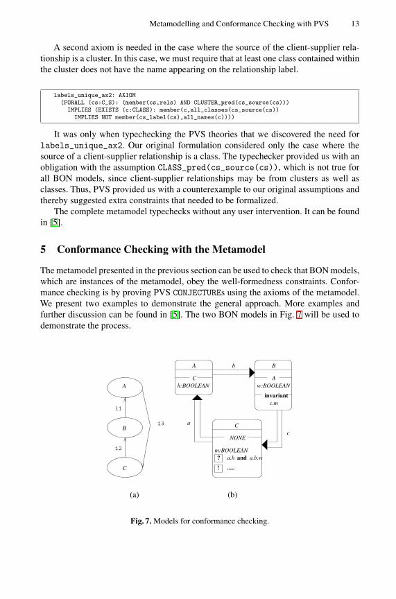
The metamodel presented in the previous section can be used to check that BON models,which are instances of the metamodel, obey the well-formedness constraints. Confor-mance checking is by proving PVS CONJECTUREs using the axioms of the metamodel.We present two examples to demonstrate the general approach. More examples andfurther discussion can be found in [5]. The two BON models in Fig. 7 will be used todemonstrate the process.
B
A
C
i1
i2
i3
(a)
invariantc.m
B
A
?
!
a.h and a.b.w
.....
C
NONE
a
b
c
m:BOOLEAN
w:BOOLEANC
A
h:BOOLEAN
(b)
Fig. 7. Models for conformance checking.
14 R.F. Paige and J.S. Ostroff
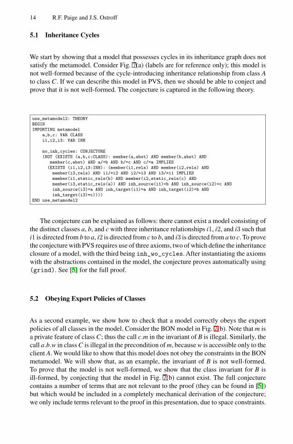
5.1 Inheritance Cycles
We start by showing that a model that possesses cycles in its inheritance graph does notsatisfy the metamodel. Consider Fig. 7(a) (labels are for reference only); this model isnot well-formed because of the cycle-introducing inheritance relationship from class Ato class C. If we can describe this model in PVS, then we should be able to conject andprove that it is not well-formed. The conjecture is captured in the following theory.
use_metamodel2: THEORYBEGINIMPORTING metamodel
a,b,c: VAR CLASSi1,i2,i3: VAR INH
no_inh_cycles: CONJECTURE(NOT (EXISTS (a,b,c:CLASS): member(a,abst) AND member(b,abst) AND
member(c,abst) AND a/=b AND b/=c AND c/=a IMPLIES(EXISTS (i1,i2,i3:INH): (member(i1,rels) AND member(i2,rels) AND
member(i3,rels) AND i1/=i2 AND i2/=i3 AND i3/=i1 IMPLIESmember(i1,static_rels(b) AND member(i2,static_rels(c) ANDmember(i3,static_rels(a)) AND inh_source(i1)=b AND inh_source(i2)=c ANDinh_source(i3)=a AND inh_target(i1)=a AND inh_target(i2)=b ANDinh_target(i3)=c))))
END use_metamodel2
The conjecture can be explained as follows: there cannot exist a model consisting ofthe distinct classes a, b, and c with three inheritance relationships i1, i2, and i3 such thati1 is directed from b to a, i2 is directed from c to b, and i3 is directed from a to c. To provethe conjecture with PVS requires use of three axioms, two of which define the inheritanceclosure of a model, with the third being inh_wo_cycles. After instantiating the axiomswith the abstractions contained in the model, the conjecture proves automatically using(grind). See [5] for the full proof.
5.2 Obeying Export Policies of Classes
As a second example, we show how to check that a model correctly obeys the exportpolicies of all classes in the model. Consider the BON model in Fig. 7(b). Note that m isa private feature of class C; thus the call c.m in the invariant of B is illegal. Similarly, thecall a.b.w in class C is illegal in the precondition of m, because w is accessible only to theclient A. We would like to show that this model does not obey the constraints in the BONmetamodel. We will show that, as an example, the invariant of B is not well-formed.To prove that the model is not well-formed, we show that the class invariant for B isill-formed, by conjecting that the model in Fig. 7(b) cannot exist. The full conjecturecontains a number of terms that are not relevant to the proof (they can be found in [5])but which would be included in a completely mechanical derivation of the conjecture;we only include terms relevant to the proof in this presentation, due to space constraints.
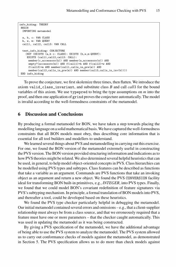
Metamodelling and Conformance Checking with PVS 15
info_hiding: THEORYBEGINIMPORTING metamodel
a, b, c: VAR CLASSh, w, m: VAR QUERYcall1, call2, call3: VAR CALL
test_info_hiding: CONJECTURE(NOT (EXISTS (a,b c: CLASS): EXISTS (h,w,m:QUERY):EXISTS (call1,call2,call3: CALL):member(c,accessors(h)) AND member(a,accessors(w)) ANDempty?(accessors(m)) AND f(call1)=h AND f(call2)=w ANDf(call3)=m AND member(call1,calls_in_pre(m)) ANDmember(call2,calls_in_pre(m)) AND member(call3,calls_in_inv(b))))
END info_hiding
To prove the conjecture, we first skolemize three times, then flatten. We introduce theaxiom valid_class_invariant, and substitute class B and call call3 for the boundvariables of this axiom. We use typepred to bring the type assumptions on m into theproof, and then one application of grind proves the conjecture automatically. The modelis invalid according to the well-formedness constraints of the metamodel.
6 Discussion and Conclusions
By producing a formal metamodel for BON, we have taken a step towards placing themodelling language on a solid mathematical basis.We have captured the well-formednessconstraints that all BON models must obey, thus describing core information that isessential for all tool builders and modellers to understand.
We learned several things about PVS and metamodelling in carrying out this exercise.For one, we found the BON version of the metamodel extremely useful in constructingthe PVS version. The BON version provided structuring information and indications as tohow PVS theories might be related. We also determined several helpful heuristics that canbe used, in general, to help model object-oriented concepts in PVS. Class hierarchies canbe modelled using PVS types and subtypes. Class features can be described as functionsthat take a variable as an argument. Commands are PVS functions that take an invokingobject as an argument and return a new object. We found the PVS CONVERSION facilityideal for transforming BON built-in primitives, e.g., INTEGER, into PVS types. Finally,we found that we could model BON’s covariant redefinition of feature signatures viaPVS’s subtyping mechanism. In principle, a formal translation of BON models into PVS,and thereafter a tool, could be developed based on these heuristics.
We found the PVS type checker particularly helpful in debugging the metamodel.Our initial metamodel contained several errors and omissions – e.g., that a client-supplierrelationship must always be from a class source, and that we erroneously required that afeature must have one or more parameters – that the checker caught automatically. Thiswas used in updating the metamodel as it was being constructed.
By giving a PVS specification of the metamodel, we have the additional advantageof being able to use the PVS system to analyze the metamodel. The PVS system allowedus to carry out conformance checks of models against the metamodel, as demonstratedin Section 5. The PVS specification allows us to do more than check models against
16 R.F. Paige and J.S. Ostroff
the metamodel: it allows us to ask questions about the metamodel, in particular, aboutemergent properties of the metamodel. These properties are not explicitly described viathe axioms of the metamodel itself; rather, they are logical consequences of the axioms.Thus, the PVS system can be used to help users of the metamodel answer pertinentquestions they may have about the metamodel.
Much work remains to be done.We plan to carry out further examples of conformancechecking, particularly concentrating on examples that require inductive proofs. We alsoplan to validate the BON metamodel itself – i.e., prove that the version of the metamodeldescribed in Section 3 is a valid BON model; this will give us greater confidence inthe validity of our work. Comparisons of our work with other formal specifications ofmetamodels will be worthwhile; preliminary efforts on this, for Alloy [6] and UML, canbe found in [5]. We also intend to tie this work in with a refinement calculus that we havebeen creating for BON [4]. In this latter work, we have provided a formal semantics formuch of BON in terms of predicates. Thus, we aim to define relationships between theBON metamodel – which captures syntactic constraints – and the formal semantics ofabstractions and relationships described elsewhere.
References
1. B. Meyer. Object-Oriented Software Construction, Prentice-Hall, 1997.2. OMG Unified Modelling Language Specification 1.3, OMG, June 1999.3. S. Owre, N. Shankar, J. Rushby, and D. Stringer-Calvert. The PVS Language Reference
Version 2.3, SRI International Technical Report, September 1999.4. R. Paige and J. Ostroff.An Object-Oriented Refinement Calculus. Technical Report CS-1999-
07, York University, December 1999.5. R. Paige and J. Ostroff. Precise and Formal Metamodelling with the Business Object Notation
and PVS. Technical Report CS-2000-03, York University, August 2000.6. M. Vaziri and D. Jackson. Some Shortcomings of OCL, the Object Constraint Language of
UML. Technical Report, MIT Laboratory for Computer Science, December 1999.7. K. Walden and J.-M. Nerson. Seamless Object-Oriented Software Development, Prentice-
Hall, 1995.
The Metamodelling Language Calculus:Foundation Semantics for UML
Tony Clark1, Andy Evans2, and Stuart Kent3
1 King’s College [email protected]
2 University of [email protected]
3 University of Kent at [email protected]
Abstract. The Metamodelling Language (MML) is a sub-set of the Uni-fied Modeling Language (UML) that is proposed as the core languageused to bootstrap the UML 2.0 definition initiative. Since it is meta-circular, MML requires an external formal semantics in order to groundit. This paper defines the MML Calculus which is used to formally defineMML and therefore provides a semantic basis for UML 2.0.
1 Introduction
The Unified Modeling Language [19] is a standardized graphical notation forexpressing the structure and behaviour of object-oriented software systems. Itis essentially a family of extensible modelling notations. The current UML def-inition lacks a number of desirable features that are currently being addressedthrough a co-ordinated effort to define a new version (UML 2.0). These featuresinclude enhancing the modularity and extensibility of UML and addressing thenotion of UML semantics.
This paper describes the semantics of the MML Calculus which used as thebasis for developing the MML metamodelling language. MML is the basis of amodular semantics-rich method called MMF [7] [5] which is being proposed bythe pUML group as a framework for the definition of UML 2.0. MML is a lan-guage mainly aimed at meta-modellers who are familiar with UML. This paperdeals with foundational semantic issues that enable MML to be a generic meta-modelling language suitable for defining UML 2.0. Features which are outside thescope of this paper include: patterns for metamodelling; details of inheritancemechanisms; details of class instantiation; details of package extension; detailsof invariant checking. These issues are dealt with in [5].
The rest of this paper is structured as follows Section 2 defines the MMLCalculus syntax and semantics. Section 3 defines the MML language in terms ofthe MML Calculus. The MML language is textual, each new construct is intro-duced and translated to the MML Calculus. Section 4 concludes by reviewingMML and describing the future directions of this work.
H. Hussmann (Ed.): FASE 2001, LNCS 2029, pp. 17–31, 2001.c© Springer-Verlag Berlin Heidelberg 2001
18 T. Clark, A. Evans, and S. Kent
2 The MML Calculus
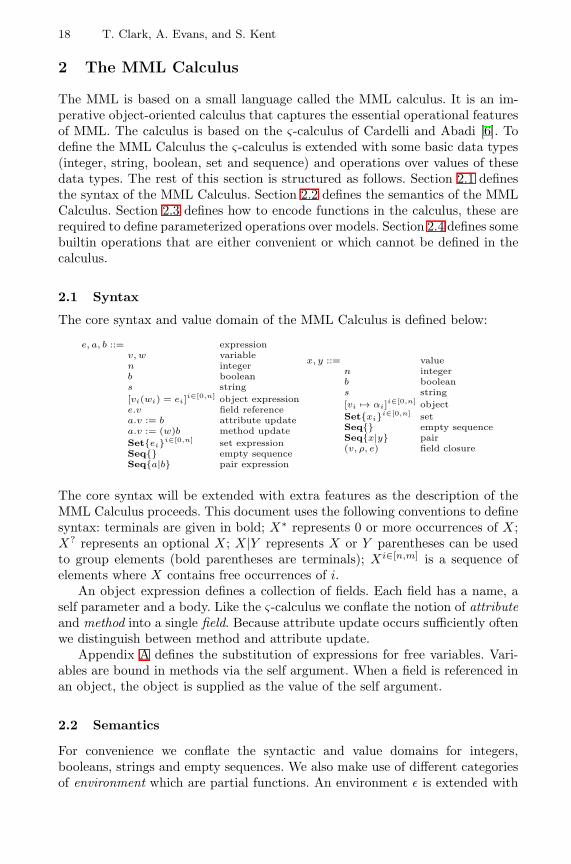
The MML is based on a small language called the MML calculus. It is an im-perative object-oriented calculus that captures the essential operational featuresof MML. The calculus is based on the ς-calculus of Cardelli and Abadi [6]. Todefine the MML Calculus the ς-calculus is extended with some basic data types(integer, string, boolean, set and sequence) and operations over values of thesedata types. The rest of this section is structured as follows. Section 2.1 definesthe syntax of the MML Calculus. Section 2.2 defines the semantics of the MMLCalculus. Section 2.3 defines how to encode functions in the calculus, these arerequired to define parameterized operations over models. Section 2.4 defines somebuiltin operations that are either convenient or which cannot be defined in thecalculus.
2.1 Syntax
The core syntax and value domain of the MML Calculus is defined below:
e, a, b ::= expressionv, w variablen integerb booleans string[vi(wi) = ei]i∈[0,n] object expressione.v field referencea.v := b attribute updatea.v := (w)b method updateSet{ei}i∈[0,n] set expressionSeq{} empty sequenceSeq{a|b} pair expression
x, y ::= valuen integerb booleans string[vi 7→ αi]i∈[0,n] objectSet{xi}i∈[0,n] setSeq{} empty sequenceSeq{x|y} pair(v, ρ, e) field closure
The core syntax will be extended with extra features as the description of theMML Calculus proceeds. This document uses the following conventions to definesyntax: terminals are given in bold; X∗ represents 0 or more occurrences of X;X? represents an optional X; X|Y represents X or Y parentheses can be usedto group elements (bold parentheses are terminals); Xi∈[n,m] is a sequence ofelements where X contains free occurrences of i.
An object expression defines a collection of fields. Each field has a name, aself parameter and a body. Like the ς-calculus we conflate the notion of attributeand method into a single field. Because attribute update occurs sufficiently oftenwe distinguish between method and attribute update.
Appendix A defines the substitution of expressions for free variables. Vari-ables are bound in methods via the self argument. When a field is referenced inan object, the object is supplied as the value of the self argument.
2.2 Semantics
For convenience we conflate the syntactic and value domains for integers,booleans, strings and empty sequences. We also make use of different categoriesof environment which are partial functions. An environment ε is extended with
The Metamodelling Language Calculus 19
an association between a key k and a value v to produce ε[k 7→ v]. Environmentssatisfy the following law:
(ε[k1 7→ v1])[k2 7→ v2] = (ε[k2 7→ v2])[k1 7→ v1] when k1 6= k2
An object is an environment that maps field names to addresses. A lexical en-vironment maps variables to values. A heap h is an environment that mapsaddresses to field closures. A field closure (v, ρ, e) contains a self variable v, abody e and a lexical environment ρ mapping the free variables of e to values.
The semantics of the MML Calculus us given by a relation h, ρ, e ⇒ x, h′which tells us the result x and final heap h′ produced by performing expressione with respect to a starting heap h in the context of a lexical environment ρ.The relation is defined as follows:
h, ρ[v 7→ x], v ⇒ x, h (1)
h, ρ, k ⇒ k, h (2)
h, ρ, [vi(wi) = ei]i∈[1,n] ⇒ [vi = αi]i∈[1,n], h[αi 7→ (wi, ρ, ei)]i∈[1,n] fresh αi (3)
h, ρ, e ⇒ x, h′[α 7→ (w, ρ′, b)]h′[α 7→ (w, ρ′, b)], ρ′[w 7→ x], b ⇒ y, h′′
h, ρ, e.v ⇒ y, h′′ x = [vi = αi, v = α]i∈[1,n](4)
h, ρ, e ⇒ x, h′
h, ρ, e.v := (w)b ⇒ x, h′[α 7→ (w, ρ, b)] x = [vi = αi, v = α]i∈[1,n] (5)
h, ρ, e ⇒ x[v 7→ f ], h′
h′, ρ, b ⇒ y, h′′
h, ρ, a.v := b ⇒ y, h′′[α 7→ (w, [v 7→ y], v)] (6)
hi, ρ, ei ⇒ xi, hi+1 i ∈ [1, n]
h1, ρ, Set{ei}i∈[1,n] ⇒ Set{xi}i∈[1,n], hn+1 (7)
h, ρ, a ⇒ x, h1
h1, ρ, b ⇒ y, h2
h, ρ, Seq{a|b} ⇒ Seq{x|y}, h2 (8)
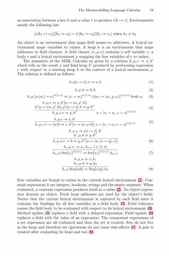
Free variables are bound to values in the current lexical environment (1). Con-stant expressions k are integers, booleans, strings and the empty sequence. Whenevaluated, a constant expression produces itself as a value (2). An object expres-sion denotes an object. Fresh heap addresses are used for the object’s fields.Notice that the current lexical environment is captured by each field since itcontains the bindings for all free variables in a field body (3). Field referencecauses the field body to be evaluated with respect to its lexical environment (4).Method update (5) replaces a field with a delayed expression. Field update (6)replaces a field with the value of an expression. The component expressions ofa set expression are all evaluated and then the set is created. Sets do not livein the heap and therefore set operations do not cause side-effects (7). A pair iscreated after evaluating its head and tail (8).
20 T. Clark, A. Evans, and S. Kent
MML is implemented as a Java program called MMT (the metamodellingtool). MMT runs a virtual machine that executes the MML Calculus. The ma-chine is defined by transforming the relation h, ρ, e ⇒, x, h′ into a transitionfunction over machine states such that ([], ρ, [e], h, ()) 7−→∗ ([x], ρ, [], h′, ()). Amachine state has the form (s, ρ, c, h, d) where the new components are: a stacks for intermediate values; a control c that is used as an instruction stream; adump d that is used to save and restore machine contexts during field reference.A prototype version of MMT is available at [27].
2.3 Functions
The kernel calculus is object-based and not function-based like the λ-calculus.However, functions can be easily embedded in the calculus thereby providing thebest of both worlds. A function with an argument v and a body b is λv.e:
e, a, b ::= . . . as before expressionλv.e function expressionlet v = a in b end local definition
A function is an object with structure: [arg(self) = self; val(self) = b[self.arg/v]]An application expression has the form a(b) where a is an expression denoting theoperator and b is an expression denoting the operand. The following equivalenceis used: a(b) = (a.copy.arg := b).val The copying (see section 2.4) is required incase the function is recursive.
The let expression introduces local definitions. Each definition consists of avariable v and a value a. The let expression has a body b. The scope of thevariable is the body of the let. A let expression is defined in terms of a function:let v = a in b end = (λv.b)(a)
2.4 Builtin Operations
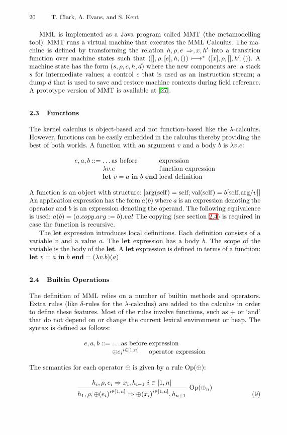
The definition of MML relies on a number of builtin methods and operators.Extra rules (like δ-rules for the λ-calculus) are added to the calculus in orderto define these features. Most of the rules involve functions, such as + or ‘and’that do not depend on or change the current lexical environment or heap. Thesyntax is defined as follows:
e, a, b ::= . . . as before expression⊕ei
i∈[1,n] operator expression
The semantics for each operator ⊕ is given by a rule Op(⊕):
hi, ρ, ei ⇒ xi, hi+1 i ∈ [1, n]
h1, ρ,⊕(ei)i∈[1,n] ⇒ ⊕(xi)
i∈[1,n], hn+1
Op(⊕n)(9)
The Metamodelling Language Calculus 21
The following binary operations are builtin: Op(+); Op(−); Op(∗); Op(/);Op(and); Op(or); Op(xor); Op(implies) When an object is copied, fresh ad-dresses (α′
i) are allocated for its fields. Note that the copy is shallow, i.e. thevalues associated with the fields are not copied:
h, ρ, e ⇒ [vi 7→ αi]i∈[1,n]
, h[αi 7→ (wi, ρi, ei)]i∈[1,n]
h, ρ, e.copy ⇒ [vi 7→ α′i]
i∈[1,n], h[αi 7→ (wi, ρ + i, ei)]
i∈[1,n]
Copying for atomic values and sets has no effect. This is expressed by a genericrule Copy(x) and a collection of rules for all integers n Copy(n), for all booleansb Copy(b), for all strings s Copy(s) and for all collections c Copy(c):
h, ρ, e ⇒ x, h′
h, ρ, e.copy ⇒ x, h′ Copy(x)
Operations on sets are based on two operations: non-deterministic selectionand adjoining an element to a set. Set extension is an operation that is con-structed from set adjoin. Basic set operations are Op(select) and Op(adjoin):select(Set{xi}i∈[1,n]) = xj for some j ∈ [1, n]adjoin(x,Set{xi}i∈[0,n]) = Set{x, xi}i∈[0,n]
The head and tail of sequences are accessed using the following operationsOp(head) and Op(tail): head(Seq{h|t}) = h and tail(Seq{h|t}) = t. EqualityOp(=) is defined as a builtin operation that returns true when atomic values arethe same, objects have the same fields, when sets have the same elements andwhen sequences are either both empty or have equal heads and tails. Otherwiseequality returns false. More sophisticated notions of equality can be constructedas methods for classes of MML object.
Boolean values support conditional commands by defining a function thatevaluates a consequent c or alternative a: true = [if( ) = λc.λa.c.val] and false =[if( ) = λc.λa.a.val] The calculus is extended with a conditional expression:
e, a, b ::= . . . as before expressionif e then a else b end conditional expression
The conditional expression is defined as follows: if e then a else b end =e.if([val( ) = a])([val( ) = b])
3 The Metamodelling Language
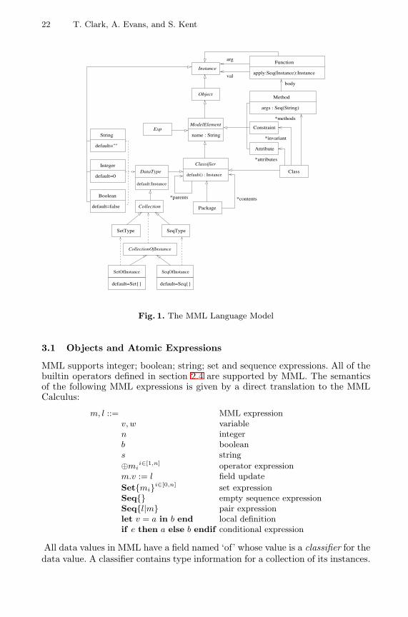
The metamodelling language is given a semantics by a translation to the MMLCalculus. MML is meta-circular, in the sense that it represents all the types andoperations in order to describe its own operation. This section defines how thefollowing MML features are represented in the MML Calculus: objects (section3.1); methods (section 3.2); types (section 3.3); classes (section 3.4); methodinvocation (section 3.5); OCL (section 3.6); packages (section 3.7). The meta-circular MML model is shown in figure 1.
22 T. Clark, A. Evans, and S. Kent
SetType SeqType
Class
Object
String
default=""
Integer
default=0
Boolean
default=false
Attribute
apply:Seq(Instance):Instance
Method
args : Seq(String)
body
val
arg
Package
*parents *contents
Function
*methods
*invariant
*attributes
CollectionOfInstance
SetOfInstance SeqOfInstance
Collection
Classifier
default() : Instance
Exp
default=Set{} default=Seq{}
default:Instance
DataType
Constraint
Instance
name : String
ModelElement
Fig. 1. The MML Language Model
3.1 Objects and Atomic Expressions
MML supports integer; boolean; string; set and sequence expressions. All of thebuiltin operators defined in section 2.4 are supported by MML. The semanticsof the following MML expressions is given by a direct translation to the MMLCalculus:
m, l ::= MML expressionv, w variablen integerb booleans string⊕mi
i∈[1,n] operator expressionm.v := l field updateSet{mi}i∈[0,n] set expressionSeq{} empty sequence expressionSeq{l|m} pair expressionlet v = a in b end local definitionif e then a else b endif conditional expression
All data values in MML have a field named ‘of’ whose value is a classifier for thedata value. A classifier contains type information for a collection of its instances.
The Metamodelling Language Calculus 23
MML knows directly about a number of builtin classifiers. Access to the builtinclassifiers is defined by the generic rule Of:
h, ρ, m ⇒ x, h′
h, ρ, m.of ⇒ y, h′ Of(x, y)
which is used to construct rules for every integer n Of(n, Integer), for everyboolean b Of(b, Boolean), for every string s Of(s,String), for every set s Of(s,SetOfInstance) and for every sequence s Of(s,SeqOfInstance). The classifiersBoolean, String, SetOfInstance and SeqOfInstance are MML objects that definethe appropriate data types.
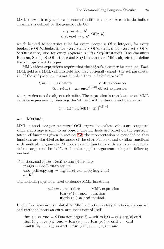
MML object expressions require that the object’s classifier be supplied. EachMML field is a MML calculus field and may optionally supply the self parameterwi. If the self parameter is not supplied then it defaults to ‘self’:
l, m ::= ... as before MML expression@m vi(wi) = mi endi∈[0,n] object expression
where m denotes the object’s classifier. The expression is translated to an MMLcalculus expression by inserting the ‘of’ field with a dummy self parameter:
[of = ( )m; vi(self) = mi]i∈[0,n]
3.2 Methods
MML methods are parameterized OCL expressions whose values are computedwhen a message is sent to an object. The methods are based on the represen-tation of functions given in section 2.3; the representation is extended so thatfunctions are classified as instances of the class Function and to allow functionswith multiple arguments. Methods extend functions with an extra implicitlydefined argument for ‘self’. A function applies arguments using the followingmethod:
Function::apply(args : Seq(Instance)):Instanceif args = Seq{} then self.valelse (self.copy.arg := args.head).val.apply(args.tail)endif
The following syntax is used to denote MML functions:
m, l ::= . . . as before MML expressionfun (v∗) m end functionmeth (v∗) m end method
Unary functions are translated to MML objects, multary functions are curriedand methods insert an extra argument named ’self’:
fun (v) m end = @Function arg(self) = self; val(f) = m[f.arg/v] endfun (v1, . . . , vn) m end = fun (v1) . . . fun (vn) m end . . . endmeth (v1, . . . , vn) m end = fun (self, v1, . . . , vn) m end
24 T. Clark, A. Evans, and S. Kent
Methods are defined by classes and invoked by sending an MML object a mes-sage. Message delivery involves looking the method up via the object’s classifierand then invoking the method with respect to the object and the arguments.This is explained in section 3.5:
l, m ::= . . . as before MML expressionm.v(li∈[0,n]
i ) send expression
3.3 Types and Type Expressions
All MML data values have classifiers; given a value x, the classifier of x is x.of.A classifier may be user defined (such as Animal or Factory) or may be definedas part of the MML language (such as String and Boolean). MML makes adistinction between data types that classify non-object values and classes thatclassify object values. This section describes the basic infrastructure of datatypes and their denotation.
All classifiers define a collection of methods and invariants for their instances.Each classifier must specify a default value to be used when a new slot usingthe classifier as a type is created; this is initially specified as Instance and isredefined in concrete sub-classes of Classifier. There are two main sub-classes ofClassifier: Class and DataType. Instances of DataType classify non-object datavalues. DataType redefines the default method to return the value of the defaultattribute.
3.4 Class Expressions
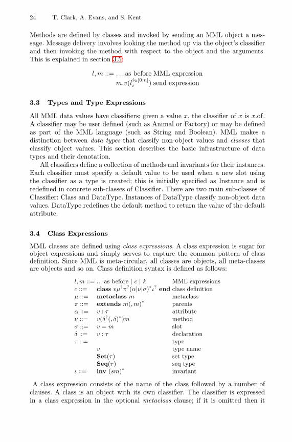
MML classes are defined using class expressions. A class expression is sugar forobject expressions and simply serves to capture the common pattern of classdefinition. Since MML is meta-circular, all classes are objects, all meta-classesare objects and so on. Class definition syntax is defined as follows:
l, m ::= ... as before | c | k MML expressionsc ::= class vµ?π?(α|ν|σ)∗ι? end class definitionµ ::= metaclass m metaclassπ ::= extends m(, m)∗ parentsα ::= v : τ attributeν ::= v(δ?(, δ)∗)m methodσ ::= v = m slotδ ::= v : τ declarationτ ::= type
v type nameSet(τ) set typeSeq(τ) seq type
ι ::= inv (sm)∗ invariant
A class expression consists of the name of the class followed by a number ofclauses. A class is an object with its own classifier. The classifier is expressedin a class expression in the optional metaclass clause; if it is omitted then it
The Metamodelling Language Calculus 25
class vmetaclass m
extends mpi
i∈[1,|p|]
vai : τa
ii∈[0,|a|]
vmi(vmij : τmi
jj∈[0,|mi|])mm
i
i∈0,|m|
vsi = ms
ii∈[0,|s|]
inv simιii∈[0,|ι|]
end
@mname = ”v”;parents = Set{mp
i }i∈[1,|p|]
attributes(v) = Set{@Attribute
name = ”vai ”;
type = τai
end}i∈[0,|a|];methods(v) = Set{
@Methodname = ”vm
i ”;args = Seq{”vmi
j ”}j∈[0,|mi|];body = meth (vmi
j )j∈[0,|mi|] mmi end
end}i∈[0,|m|];invariant(v) = Set{
@Constraintname = si;body = meth () mι
i endend}i∈[0,|ι|];
vsi (v) = ms
ii∈[0,|s|]
end
Fig. 2. Translation of Class Definition to Object Expression
defaults to Class. A class has multiple parents from which it inherits variousdefinitions. The parents of a class are expressed in the optional parents clause; ifit is omitted then the class will have the single parent Object. A class contains anumber of definitions for attributes, methods and slots in the definitions clause.The attributes define the slots contained in instances of the class and the methodsdefine the behaviour of the instances. The slot definitions allow extra informationto be added to the class being defined where there is no syntax support. Extraslots are required when using a non-standard meta-class.
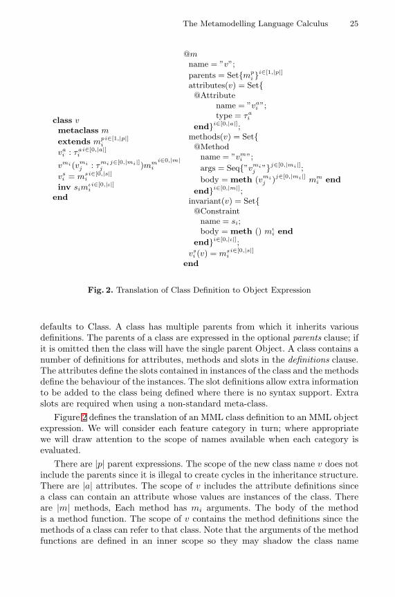
Figure 2 defines the translation of an MML class definition to an MML objectexpression. We will consider each feature category in turn; where appropriatewe will draw attention to the scope of names available when each category isevaluated.
There are |p| parent expressions. The scope of the new class name v does notinclude the parents since it is illegal to create cycles in the inheritance structure.There are |a| attributes. The scope of v includes the attribute definitions sincea class can contain an attribute whose values are instances of the class. Thereare |m| methods, Each method has mi arguments. The body of the methodis a method function. The scope of v contains the method definitions since themethods of a class can refer to that class. Note that the arguments of the methodfunctions are defined in an inner scope so they may shadow the class name
26 T. Clark, A. Evans, and S. Kent
v. There are |ι| constraints defined for the invariant of a class. The scope ofv includes the invariant. There are |s| slots. The scope of v includes the slotvalues. The slots should correspond to attributes of the meta-class m that arenot explicitly introduced by the class definition transformation.
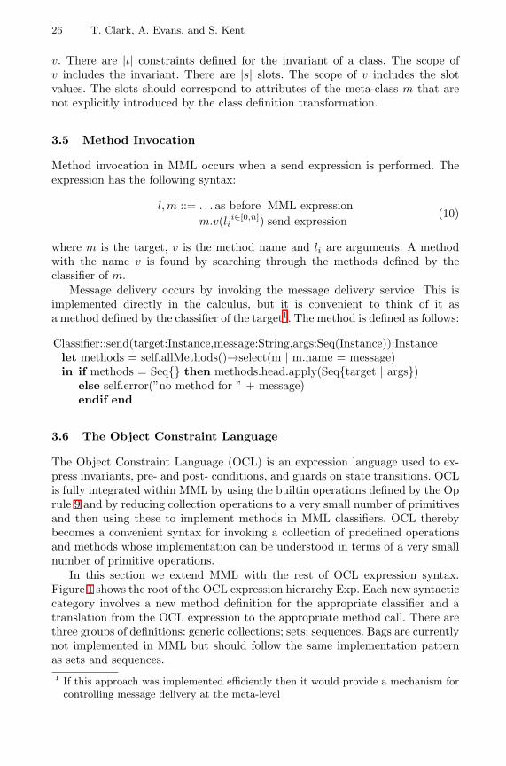
3.5 Method Invocation
Method invocation in MML occurs when a send expression is performed. Theexpression has the following syntax:
l, m ::= . . . as before MML expressionm.v(lii∈[0,n]) send expression
(10)
where m is the target, v is the method name and li are arguments. A methodwith the name v is found by searching through the methods defined by theclassifier of m.
Message delivery occurs by invoking the message delivery service. This isimplemented directly in the calculus, but it is convenient to think of it asa method defined by the classifier of the target1. The method is defined as follows:
Classifier::send(target:Instance,message:String,args:Seq(Instance)):Instancelet methods = self.allMethods()→select(m | m.name = message)in if methods = Seq{} then methods.head.apply(Seq{target | args})
else self.error(”no method for ” + message)endif end
3.6 The Object Constraint Language
The Object Constraint Language (OCL) is an expression language used to ex-press invariants, pre- and post- conditions, and guards on state transitions. OCLis fully integrated within MML by using the builtin operations defined by the Oprule 9 and by reducing collection operations to a very small number of primitivesand then using these to implement methods in MML classifiers. OCL therebybecomes a convenient syntax for invoking a collection of predefined operationsand methods whose implementation can be understood in terms of a very smallnumber of primitive operations.
In this section we extend MML with the rest of OCL expression syntax.Figure 1 shows the root of the OCL expression hierarchy Exp. Each new syntacticcategory involves a new method definition for the appropriate classifier and atranslation from the OCL expression to the appropriate method call. There arethree groups of definitions: generic collections; sets; sequences. Bags are currentlynot implemented in MML but should follow the same implementation patternas sets and sequences.1 If this approach was implemented efficiently then it would provide a mechanism for
controlling message delivery at the meta-level
The Metamodelling Language Calculus 27
Collections. Many OCL operations work on all types of collection. Typicallythese operations are implemented in terms of lower-level operations that arespecific to the particular type of collection:
l, m ::= . . . as before MML expressionm → v(m(, m)∗)? collection operationm → v(w|l) quantified operationm → iterate(vw = m|m) iteration
Collection operation names are: size, includes (an element), count (ocurrencesof an element), includesAll (elements of another collection), isEmpty, notEmpty,sum (the elements). Quantified operations are exists and forAll. The class Collec-tionOfInstance is the root of the collection type hierarchy. Its implementation isan example of how MML supports multiple meta-levels. Its meta-class Collectionis a sub-class of DataType and therefore is the class of all collection types.
There are two different categories of expression: those that introduce newvariables (exists, forAll and iterate) and those that do not. Expressions thatdo not introduce new variables are translated to send expressions in MML. Forexample m → includes(l) becomes m.includes(l), with the following implemen-tation:
CollectionOfInstance::includes(o : Instance) : Booleanself→ count(o) > 0
CollectionOfInstance::count(o : Instance) : Integerself→ iterate (v1v2 = 0| if v1.equals(o) then v2 + 1 else v2 endif)
Expressions that introduce variables are translated to send expressions that bindthe variables using one or more functions. Functions are objects in MML and maybe passed as arguments to methods. The following table shows the translations:
m → exists(v|l) m.exists(fun(v) l end)m → forAll(v|l) m.forAll(fun(v) l end)
m1 → iterate(v1v2 = m2|m3) m1.iterate(fun(v1, v2) m3 end, m2)
The quantified operations are defined in terms of iterate. Iterate is abstract atthe collection level and is implemented by each concrete type of collection.
CollectionOfInstance::exists(f : Function) : Booleanself→iterate(e a = false | a or f.apply(Seq{e}))
CollectionOfInstance::forAll(f : Function) : Booleanself→iterate(e a = true | a and f.apply(Seq{e}))
There is nothing special about the collection method definitions. MML is opento extension just like any other object-oriented model. The combination of poly-morphism, dynamic binding and first class functions provides a very powerfulabstraction and extension mechanism.
28 T. Clark, A. Evans, and S. Kent
Sets. Set expression syntax is the same as that for collections. Set operationsare: union; intersection; −; including (adjoin); symmetricDifference; asSequence.Parametric operations are: select (positive filter); reject (negative filter); collect(map). In each case the parametric operations are translated to send expressionswith a function argument.
The class SetOfInstance is a sub-class of CollectionOfInstance and imple-ments set operations. Many of the methods are implemented in terms of otherSetOfInstance methods. The only set operations that rely on primitive opera-tions are including that uses adjoin and iterate that uses select. These primitivesalong with the empty set can be viewed as being the essence of sets in MML.The following shows the definition of iterate:
SetOfInstance::iterate(v:Instance,f:Function):Instanceif self = Set{} then velse let e = self.select
in (self→excluding(e)).iterate(f.apply(Seq{e,v}),f) endendif
Sequences. OCL sequence expressions are implemented in MML and the MMLCalculus using the same pattern of features as defined in the previous section.OCL sequences ultimately depend upon two primitive operations: head and tail.These are builtin to the OCL Calculus as defined in section 2.4.
3.7 Package Expressions
A package in MML is a container of classes and packages similar to those definedby the Catalysis approach [12]. Each class and package has a name and navi-gation expressions can be used to extract package contents. A package is itselfa classifier; it is used to classify collections of objects. It is beyond the scope ofthis paper to deal with this feature of MML in detail; as a classifier, a packagemust have parents, methods and invariants. A package is created using a packageexpression:
l, m ::= ... as before | p MML expressionsp ::= package vµ?π?(c|k|p)∗(ν|σ)∗
ι? end package definition
A package definition expression is translated to an object expression in the MMLCalculus. This translation is the same as that shown in figure 2 except that apackage has an extra field called contents whose value is a set of classifiers. Eachclassifier defined by the package is also a field of the package; this allows us tonavigate to package elements using names. The name of the package is scopedover each of the contents; this allows the contents to be mutually recursive.
MML consists of a collection of packages. It is beyond the scope of this paperto describe the package structure of MML. Consider a package called conceptsthat defines the core modelling concepts in MML. Figure 3 shows how such apackage is expressed in MML and given a semantics by a translation to the MMLCalculus; the details of class translation are omitted, but follow the definitiongiven in figure 2.
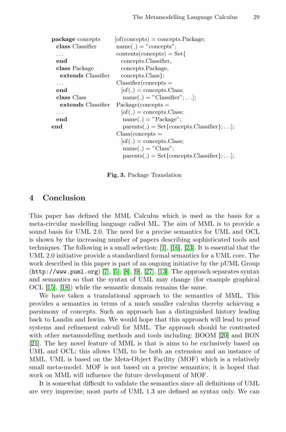
The Metamodelling Language Calculus 29
package conceptsclass Classifier. . .endclass Packageextends Classifier
. . .endclass Classextends Classifier
. . .end
end
[of(concepts) = concepts.Package;name( ) = ”concepts”;contents(concepts) = Set{
concepts.Classifier,concepts.Package,concepts.Class};
Classifier(concepts =[of( ) = concepts.Class;name( ) = ”Classifier”; . . .];
Package(concepts =[of( ) = concepts.Class;name( ) = ”Package”;parents( ) = Set{concepts.Classifier}; . . .];
Class(concepts =[of( ) = concepts.Class;name( ) = ”Class”;parents( ) = Set{concepts.Classifier}; . . .];
Fig. 3. Package Translation
4 Conclusion
This paper has defined the MML Calculus which is used as the basis for ameta-circular modelling language called ML. The aim of MML is to provide asound basis for UML 2.0. The need for a precise semantics for UML and OCLis shown by the increasing number of papers describing sophisticated tools andtechniques. The following is a small selection: [1], [16], [23]. It is essential that theUML 2.0 initiative provide a standardized formal semantics for a UML core. Thework described in this paper is part of an ongoing initiative by the pUML Group(http://www.puml.org) [7], [5], [8], [9], [27], [13]. The approach separates syntaxand semantics so that the syntax of UML may change (for example graphicalOCL [15], [18]) while the semantic domain remains the same.
We have taken a translational approach to the semantics of MML. Thisprovides a semantics in terms of a much smaller calculus thereby achieving aparsimony of concepts. Such an approach has a distinguished history leadingback to Landin and Iswim. We would hope that this approach will lead to proofsystems and refinement calculi for MML. The approach should be contrastedwith other metamodelling methods and tools including: BOOM [20] and BON[21]. The key novel feature of MML is that is aims to be exclusively based onUML and OCL; this allows UML to be both an extension and an instance ofMML. UML is based on the Meta-Object Facility (MOF) which is a relativelysmall meta-model. MOF is not based on a precise semantics; it is hoped thatwork on MML will influence the future development of MOF.
It is somewhat difficult to validate the semantics since all definitions of UMLare very imprecise; most parts of UML 1.3 are defined as syntax only. We can
30 T. Clark, A. Evans, and S. Kent
report that the implementation of MML based on the calculus in MMT hasbeen used to develop MML programs of about 3000 lines of code; based on thisempirical evidence we can tentatively claim that MML behaves as expected.
The semantics described in this paper is imperative and operational. In thatsense it is richer than UML whose informal semantics is declarative. However,the MML Calculus has a strictly declarative sub-language which captures thesame semantics as other model-based approaches to UML semantics such as [24]and those that use Z.
The use of meta-circular language definitions has a distinguished history, forexample CLOS [2], ObjVLisp [3] [4] [11] and Smalltalk [14] use meta-classes. Thetheory of meta-classes is discussed in [17]. The use of meta-models to describeUML and OCL is the accepted technique [22].
This is ongoing work. Core MML is nearing completion and a tool, MMT,that supports definition, use and checking of MML is under development. Weintend to consolidate MML in the near future, for example by adding types [10],[25]; then, MML will be used to define a number of languages that contribute tothe UML family.
References
1. Bottoni P., Koch M., Parisi-Presicce F., Taentzer G. (2000) Consistency Checkingand Visualization of OCL Constraints. In Evans A., Kent S., Selic B. (eds) UML2000, LNCS 1939, 278 – 293, Springer-Verlag.
2. Bobrow D. (1989) Common Lisp Object System Specification. Lisp and SymbolicComputation, 1(3/4).
3. Briot J-P, Cointe P. (1986) The ObjVLisp Model: Definition of a Uniform Reflex-ive and Extensible Object-oriented Language. In Proceedings of ECAI 1986.
4. Briot J-P., Cointe P. (1987) A Uniform Model for Object-oriented LanguagesUsing the Class Abstraction. In proceedings of IJCAI 1987.
5. Brodsky S., Clark A., Cook S., Evans A., Kent S. (2000) A feasibility Study inRearchitecting UML as a Family of Languages Using a Precise OO MetamodellingApproach. Available at http://www.puml.org/mmt.zip.
6. Cardelli L., Abadi M. (1996) A Theory of Objects. Springer-Verlag.7. Clark A., Evans A., France R., Kent S., Rumpe B. (1999) Response to IML 2.0
Request for Information. Available athttp://www.puml.org/papers/RFIReponse.PDF.
8. Clark A., Evans A., Kent S. (2000) The Specification of a Reference Implemen-tation for UML. Special Issue of L’Objet.
9. Clark A., Evans A., Kent S. (2000) Profiles for Language Definition. Presentedat the ECOOP pUML Workshop, Nice.
10. Clark A. (1999) Type-checking OCL Constraints. In France R. & Rumpe B. (eds)UML ’99 LNCS 1723, Springer-Verlag.
11. Cointe, P. (1987) Metaclasses are First Class: the ObjVLisp Model. In Proceedingsof OOPSLA 1987.
12. D’Souza D., Wills A. C. (1998) Object Components and Frameworks with UML– The Catalysis Approach. Addison-Wesley.
The Metamodelling Language Calculus 31
13. Evans A., Kent S. (1999) Core metamodelling semantics of UML – The pUMLapproach. In France R. & Rumpe B. (eds) UML ’99 LNCS 1723, 140 – 155,Springer-Verlag.
14. Goldberg A., Robson D. (1983) Smalltalk-80: The Language and Its Implemen-tation. Addison Wesley.
15. Howse J., Molina F., Kent S., Taylor J. (1999) Reasoning with Spider Diagrams.IEEE Symposium on Visual Languages ’99, 138 – 145. IEEE CS Press.
16. Hussmann H., Demuth B., Finger F. (2000) Modular Architecture for a ToolsetSupporting OCL In Evans A., Kent S., Selic B. (eds) UML 2000, LNCS 1939LNCS, 278 – 293 , Springer-Verlag.
17. Jagannathan S. (1994) Metalevel Building Blocks for Modular Systems. ACMTOPLAS 16(3).
18. Kent S. (1997) Constraint Diagrams: Visualizing Invariants in Object-OrientedModels. In Proceedings of OOPSLA ’97, 327 – 341.
19. Object Management Group (1999) OMG Unified Modeling Language Specifica-tion, version 1.3. Available at http://www.omg.org/uml.
20. Overgaard G. (2000) Formal Specification of Object-Oriented Metamodelling.FASE 2000, LNCS 1783.
21. Paige & Ostroff (2001) Metamodelling and Conformance Checking with PVS. Tobe presented at FASE 2001.
22. Richters M., Gogolla M. (1999) A metamodel for OCL. In France R. & RumpeB. (eds) UML ’99 LNCS 1723, 156 – 171, Springer-Verlag.
23. Richters M., Gogolla M. (2000) Validating UML Models and OCL Constraints.In Evans A., Kent S., Selic B. (eds) UML 2000 LNCS 1939, 265 – 277, Springer-Verlag.
24. Richters M., Gogolla M. (2000) A Semantics for OCL pre and post conditions.Presented at the OCL Workshop, UML 2000.
25. Schurr A. (2000) New Type Checking Rules for OCL (Collection) Ex-pressions. Presented at the OCL Workshop at UML 2000. Available fromhttp://www.scm.brad.ac.uk/research/OCL2000.
26. Warmer J., Kleppe A. (1999) The Object Constraint Language: Precise Modelingwith UML. Addison-Wesley.
27. The MMT Tool. Available at http://www.puml.org/mmt.zip.
A Substitution for Free Variables
v[e/w] =
{e when v = wv otherwise variable
k[e/v] = k atomic expression[vi(wi) = ei]i∈[1,n][e/v] = [(vi(wi) = ei)[e/v]]i∈[1,n] object expressions
(v(w) = a)[b/w′] =
{v(w) = a when w′ = wv(w) = (a[b/w′]) otherwise method
a.v[b/w] = (a[b/w]).v field reference(a.v := b)[e/w] = (a[e/w]).v := (b[e/w]) field update
(a.v := (w)b)[e/w′] =
{(a[e/w′]).v := (w)b when w′ = w(a[e/w′]).v := (w)(b[e/w′]) otherwise method update
Set{ei}i∈[1,n][e/v] = Set{ei[e/v]}i∈[1,n] set expressionSeq{a|b}[e/v] = Set{a[e/v]|b[e/v]} pair
Compositional Checking ofCommunication among Observers?
Ralf Pinger and Hans-Dieter Ehrich
Abteilung Informationssysteme, Technische Universitat BraunschweigPostfach 3329, D-38023 Braunschweig, Germany
{R.Pinger|HD.Ehrich}@tu-bs.deFax: +49-531-3913298
Abstract. Observers are objects inside or outside a concurrent objectsystem carrying checking conditions about objects in the system (pos-sibly including itself). In a companion paper [EP00], we show how tosplit and localise checking conditions over the objects involved so thatthe local conditions can be checked separately, for instance using modelchecking. As a byproduct of this translation, the necessary communica-tion requirements are generated, taking the form of RPC-like action calls(like in a CORBA environment) among newly introduced communica-tion symbols. In this paper, we give an algorithmic method that matchesthese communication requirements with the communication pattern cre-ated during system specification and development. As a result, correct-ness of the latter can be proved. In case of failure, the algorithm giveswarnings helping to correct the communication specification.
Keywords. compositionality, distributed logic, model checking, mod-elling and design, object system, temporal logic, verification.
1 Introduction
In this paper, we elaborate on a novel compositional checking technique fordistributed object systems that may be used for deductive verification, modelchecking or testing. In a companion paper [EP00], we show how to split andlocalise checking conditions over the objects involved so that the local conditionscan be checked separately. Here we show how the necessary communication andthus the overall object system can be checked.
An object system in our sense is a community of sequential objects operatingconcurrently and communicating via synchronous RPC-like message passing (likein a CORBA environment). Objects may be distributed over sites.
The complexity of system verification is exponential in the number of con-current components: the system state space “explodes” in size. To overcomethis problem, compositional specification and verification techniques have beenwidely discussed. The idea is best expressed in [dR97]:? This work was partially supported by the EU under ESPRIT IV Working Group
22704 ASPIRE.
H. Hussmann (Ed.): FASE 2001, LNCS 2029, pp. 32–44, 2001.c© Springer-Verlag Berlin Heidelberg 2001
Compositional Checking of Communication among Observers 33
“The purpose of a compositional verification approach is to shift the bur-den of verification from the global level to the local, component, level, sothat global properties are established by composing together independently(specified and) verified component properties”.
The benefit of compositional verification is obvious: instead an exponentialincrease of the overall verification amount, compositional verification has a linearcomplexity with respect to the number of components.
The first compositional verification approach was given by [MC81] where arule for composing networks was given that is analogous to pre- and postcon-ditions in sequential program proving. In [Pnu85], Pnueli defined the assume-guarantee approach that is very powerful but requires some human interactionfor dividing the global property into suitable modular properties. Abadi andLamport [AL93,AL95] used a modular way of specifying systems and were ableto include liveness properties in the guarantee parts of the assume-guaranteerules. Moreover, their approach deals with fairness and hiding.
Clarke, Long and McMillan adapted these techniques for model checking[CLM89]. Their approach employs interfaces which represent only that part of asubsystem which is observable by one particular other subsystem. By composingsuch an interface with the corresponding subsystem, formulae can be verifiedin the smaller system which are true in the entire system. The performance ofthis approach depends heavily on the size of the interfaces, so it is best suitedfor loosely coupled systems. Another limitation deals with the fact that theinterface rule can only handle boolean combinations of temporal properties ofthe individual processes.
Grumberg and Long as well as Josko developed machine supported versionsof compositional verification. Grumberg and Long used a subclass of CTL whichdoes not allow existentially quantified path formulae [GL94]. Another limitationis that all components of the system have to synchronise on a transition. Thisis suitable for clocked systems like, e.g., in hardware but it is not appropriatefor software components which are distributed over a computer network or evenover the internet. Josko [Jos89] used a modular but quite restricted version ofCTL for writing assertions in an assume-guarantee way. Moreover, the number ofverification steps grows exponentially with the number of until/unless formulaein the assumptions.
Fiadeiro and Maibaum give foundational aspects of object-oriented systemverification in [FM95]. They have developed sound inference rules for reasoningabout object system. However, there is no tool support for this approach.
The idea we put forward here does not restrict the logic: we employ a dis-tributed extension of full CTL for specifying the checking conditions. The added“distributed” facility consists of nesting statements about communication withconcurrent objects. This logic, called D1, can be automatically translated to thelogic D0 that also employs full CTL locally but has a very restricted communi-cation mechanism reflecting RPC-like action calling.
Our method is orthogonal to the other compositionality approaches, it maybe combined with the others. Which combinations are useful is subject to further
34 R. Pinger and H.-D. Ehrich
study. In a sense, traditional compositionality approaches can be embedded intoour approach: the traditional global view may be seen as bound to an “externalobserver” in our sense.
Object-oriented modelling and design is widely accepted; this is given evi-dence, among others, by the fact that UML has become an industrial standard.The work reported here is performed in the context of developing the Troll lan-guage, method and tools for information systems development [HDK+97,DH97,GKK+98] where we put some effort in investigating the logic and mathematicalfoundations of the approach. The semantics of Troll is based on distributedtemporal logic like the one used in this paper. Its use for specification is describedin [ECSD98,EC00].
In the next section, we give a brief and informal introduction to our approach,details can be found in [EP00]. We use the example given there in order todemonstrate how to distribute “global” assertions over the objects involved,introducing communication requirements in the form of RPC-like communicationrules. Here we capitalise on a result on translating distributed logics published in[ECSD98,EC00]. In the 3rd section we present the main result of this paper, analgorithmic method that matches these communication requirements with thecommunication pattern created during system specification and development.
2 Distributing Checking Conditions
The idea is illustrated by an n-process mutual exclusion example where we iden-tify an object with a process. A process may be idle or trying to enter the criticalregion; only one process at a time is allowed to enter its critical region.
Example 1 (Mutual Exclusion). We present a “self-organising” version of the n-process mutual exclusion problem that is advantageous in cases where the systemis at rest most of the time because then there is no communication traffic. Inthe beginning, all processes P0, . . . , Pn−1 are idle, and the system is at rest.When k processes try to enter the critical region, 0 < k ≤ n, one is chosennondeterministically and a token ring of all processes is initialised, giving allprocesses in turn a chance to enter the critical region if they want to. Wheneverall processes are idle, the system may go at rest again, i.e., the token ring is putdormant.
A state diagram of Pi is shown in figure 1. Each process Pi, i ∈ {0, . . . , n−1}has four states: {idli, tryi, criti, fwdi}. Process Pi has the token iff it is in one ofits right-hand side states, criti or fwdi, respectively. A transition carrying a setof actions as a label is an abbreviation for a set of transitions between the samepair of states, one for each action in the set.
The token ring is established as follows. Each process Pi receives the tokenfrom its right-hand neighbour Pi+1 mod n and sends it to its left-hand neighbourPi−1 mod n. Transmitting the token is modelled by two actions for each processPi: ti+1 mod n represents receiving the token, and ti represents forwarding it. Ofcourse, forwarding in Pi synchronises with receiving in Pi−1 mod n, represented
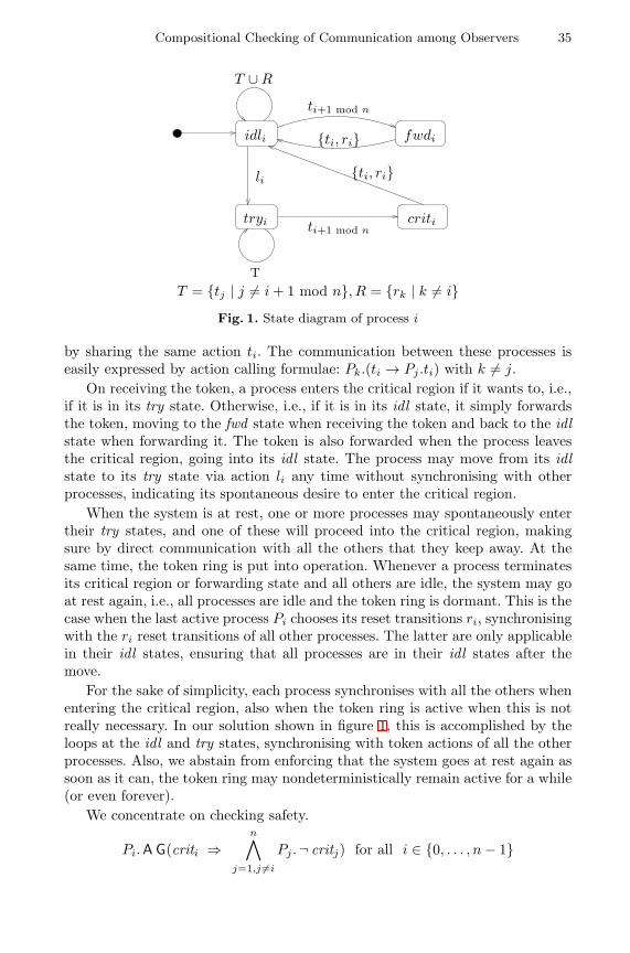
Compositional Checking of Communication among Observers 35
tryi criti
{ti, ri}
ti+1 mod n
fwdiidli
li
ti+1 mod n
T ∪R
T
{ti, ri}
T = {tj | j 6= i+ 1 mod n}, R = {rk | k 6= i}Fig. 1. State diagram of process i
by sharing the same action ti. The communication between these processes iseasily expressed by action calling formulae: Pk.(ti → Pj .ti) with k 6= j.
On receiving the token, a process enters the critical region if it wants to, i.e.,if it is in its try state. Otherwise, i.e., if it is in its idl state, it simply forwardsthe token, moving to the fwd state when receiving the token and back to the idlstate when forwarding it. The token is also forwarded when the process leavesthe critical region, going into its idl state. The process may move from its idlstate to its try state via action li any time without synchronising with otherprocesses, indicating its spontaneous desire to enter the critical region.
When the system is at rest, one or more processes may spontaneously entertheir try states, and one of these will proceed into the critical region, makingsure by direct communication with all the others that they keep away. At thesame time, the token ring is put into operation. Whenever a process terminatesits critical region or forwarding state and all others are idle, the system may goat rest again, i.e., all processes are idle and the token ring is dormant. This is thecase when the last active process Pi chooses its reset transitions ri, synchronisingwith the ri reset transitions of all other processes. The latter are only applicablein their idl states, ensuring that all processes are in their idl states after themove.
For the sake of simplicity, each process synchronises with all the others whenentering the critical region, also when the token ring is active when this is notreally necessary. In our solution shown in figure 1, this is accomplished by theloops at the idl and try states, synchronising with token actions of all the otherprocesses. Also, we abstain from enforcing that the system goes at rest again assoon as it can, the token ring may nondeterministically remain active for a while(or even forever).
We concentrate on checking safety.
Pi.A G(criti ⇒n∧
j=1,j 6=i
Pj .¬ critj) for all i ∈ {0, . . . , n− 1}
36 R. Pinger and H.-D. Ehrich
The assertions are written in the distributed version of CTL that we introducebelow. It should be intuitively clear what they mean. The i-th safety conditionmakes an assertion about all the other processes: they must not be in the criticalregion when the i-th process is.
In order to check safety, and assuming that the communication is correct, allwe have to do is to prove the following.
Pi.(criti ⇒ ti+1 mod n) for all i ∈ {0, . . . , n− 1}, and
Pj .(ti+1 mod n ⇒ ¬ critj) for all j 6= i, j ∈ {0, . . . , n− 1}The first condition says that Pi cannot be in the critical region unless it has
been entered via action ti+1 mod n. The second condition says that if ti+1 mod n
has happened, no other process can be in the critical region. These conditionsare local, they are obviously satisfied by our solution.
We note in passing that also other correctness criteria (cf. [HR00]) are satis-fied by our solution: liveness (each process which is in its try state will eventuallyenter the critical section), non-blocking (a process can always request to enterthe critical region) and no-strict-sequencing (processes need not enter the criti-cal region in strict sequence). We do not elaborate on these conditions here. Acompositional proof for the liveness property can be found in [EP00].
It remains to prove that communication indeed works correctly. What mustbe shown is the following.
Pi.(ai ⇒ Pj .ai) and Pj .(ai ⇒ Pi.ai) for i, j ∈ {0, . . . , n− 1}.
where a may stand for t or r: each token or reset action synchronises withits counterparts in the other processes. For i = j, the formulae are trivial. Theprecise meaning of these formulae will be made clear in the next section.
Observers are objects inside or outside a concurrent object system carry-ing checking conditions about objects in the system (possibly including itself).Let I be a finite set of observers (or, rather, observer identifiers). Each ob-server i ∈ I has an individual set Ai of action symbols expressing which actionhappens during a given transition, and an individual set Σi of state predicatesymbols expressing which attributes have which values in a given state. LetΣ = (I, {Ai, Σi}i∈I) be the observer signature. Our multi-observer logic is likethe distributed logic D1 described in [ECSD98,EC00] but instantiated with CTL,the computation tree logic due to E. Clarke and A.E. Emerson [CE81]. This logicD1(Σ) — or D1 for short when Σ is clear from context — is defined as follows.
Definition 1. The observer logic D1 is the I-indexed family of local logics{Di
1}i∈I where, for each i ∈ I, Di1 is CTL over Ai and Σi with the added
possibility of using formulae in Dj1, j ∈ I, j 6= i as subformulae.
A given D1 formula i.(. . . j.ψ . . . ) with a communication subformula j.ψ ∈Dj
1, j 6= i, means that i communicates — or synchronises — with j and assertsthat ψ is true for j at this moment of synchronisation. Thus, each D1 formula
Compositional Checking of Communication among Observers 37
is bound to an observer, and each formula of another observer may serve as asubformula, representing communication with that observer.
For instance, the safety formulae in example 1 are in D1: the subformulaePj .¬ critj , j ∈ {1, . . . , n}, j 6= i, are communication subformulae.
As shown in example 1 above, these assertions are transformed to purelylocal formulae and primitive communication formulae,
Pi.(ai ⇒ Pj .ai) and Pj .(ai ⇒ Pi.ai) for i, j ∈ {0, . . . , n− 1}.
All these formulae are in D1. The latter communication subformulae charac-terise RPC, the basic middleware communication mechanism.
Formulae of this kind constitute the sublogic D0 which we define below.First we give a more detailed and more precise definition of D1 semantics.
We assume a family M = {Mi}i∈I of models to be given, one for each observer,where Mi = (Si,→i, Li), i ∈ I. For each observer i, Si is its set of states,→i⊆ Si×Ai×Si is its action-labelled state transition relation, and Li : Si →i 2Σi
is its state labelling function. We write s a→i t for (s, a, t) ∈→i. As in example1, we may extend the model to allow for finite sets B of actions as transitionlabels: s B→ s′ ⇔ ∀a ∈ B : s a→ s′.
We assume that the reader is familiar with the conventional CTL semantics(cf., e.g., [HR00]): it defines the meaning of Mi, si |=i ϕ for every observer iwhere si ∈ Si and ϕ ∈ Di
1, as long as ϕ does not contain any communicationsubformula — and as long as there are no action symbols, i.e. |Ai| = 1 for everyobserver i.
Action symbols are easily introduced by “pushing them into the states”: givena model M = (S,→, L) where →⊆ S × A × S and L : S → 2Σ , we define themodel M′ = (S′,→′, L′), →′⊆ S′ × S′, L′ : S′ → Ai × 2Σi , by
S′ = S ×A× S
(s1a1→ s2) →′ (s3
a2→ s4) iff s2 = s3
L′(s1a→ s2) = (a, L(s2))
for all s1, s2, s3, s4 ∈ S′ and all a, a1, a2 ∈ A. Of course, s →′ t stands for(s, t) ∈→′. We use action symbols a also as action occurrence predicates meaningthat action a occurs during a transition (in M) or during a state (in M′),respectively.
Our construction is different from the ACTL construction given in [dNV90]where a new state sa is introduced on each transition labelled a. Our constructiongives us states with action symbols as state predicates; this is essential for thetranslation of D1 to D0 as described in the following section.
Capturing communication is not quite so easy. Note that with treating theactions as described above, we now synchronise states rather than transitions.However, whether a state of one observer synchronises with a given state ofanother one does not only depend on the current state of the former but onwhat happened before in the latter. We refer to [EC00,EP00] for more detailson this matter.
38 R. Pinger and H.-D. Ehrich
Now we demonstrate how D1 formulae can be translated to D0 formulae in asound and complete way where D0 ⊆ D1 is a sublogic featuring sketched above.Full details of the translation as well as soundness and completeness proofs aregiven in [EC00]. We first introduce D0, outline the translation rules, and showhow the translation can be utilised to transform global assertions (in D1) intomultiple local assertions (in D0). This way, the communication primitives andthe local assertions for the objects involved are separated so that they togetherguarantee the original global assertion.
For defining D0, we assume again that a family of object signatures Σ =(I, {Ai, Σi}i∈I) is given which we do not show explicitly in our notation.
Definition 2. The object sublogic D0 ⊆ D1 is the I-indexed family of local logics{Di
0}i∈I where, for each i ∈ I, each formula in Di0 is either a CTL formula over
Ai, Σi and @j, j ∈ I, or a communication formula of the form ai ⇒ j.aj , j ∈I, j 6= i, ai ∈ Ai, aj ∈ Aj .
The predicates i.@j mean the same as i.j.¬⊥ in D1, namely that i commu-nicates with j. But this must be given an extra symbol in D0 because i.j.¬⊥ isnot a formula in D0. Note that i.@i is trivially true: each object synchroniseswith itself all the time.
Examples of D0 formulae have been given above. For the straightforwardproof that D0 is indeed a sublogic of D1, we refer to [EC00].
The idea of the translation is as follows. Let an assertion ϕ ∈ Di1 be given
saying, somewhere in context, that an assertion ψ holds for j,
ϕ ⇔ i.(. . . j.ψ . . . ),
where j.ψ is in D0, i.e., ψ does not have a communication subformula. Themeaning is that i transmits a “message” q to j,
ϕ ⇔ i.(. . . q . . . ),
that is equivalent in j to the validity of ψ during communication with i,
δ ⇔ j.(q ⇔ @i ∧ ψ)
q is a new action symbol in i as well as in j, i.e., there are local actions i.q in iand j.q in j “calling” each other. This communication is captured by
α ⇔ i.(q ⇒ j.q)β ⇔ j.(q ⇒ i.q)
The resulting formulae δ, α and β are in D0. ϕ may still be in D1 − D0, butthe number of communication subformulae has decreased by one. With α and βas defined above, the translation step is sound (ϕ implies ϕ and δ) and complete(ϕ and δ imply ϕ).
The translation of arbitrary D1 formulae is accomplished by iterating theabove step inside–out until no communication subformulae are left. Together
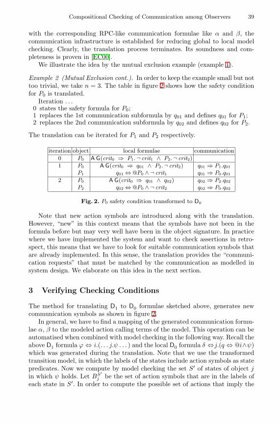
Compositional Checking of Communication among Observers 39
with the corresponding RPC-like communication formulae like α and β, thecommunication infrastructure is established for reducing global to local modelchecking. Clearly, the translation process terminates. Its soundness and com-pleteness is proven in [EC00].
We illustrate the idea by the mutual exclusion example (example 1).
Example 2 (Mutual Exclusion cont.). In order to keep the example small but nottoo trivial, we take n = 3. The table in figure 2 shows how the safety conditionfor P0 is translated.
Iteration . . .0 states the safety formula for P0;1 replaces the 1st communication subformula by q01 and defines q01 for P1;2 replaces the 2nd communication subformula by q02 and defines q02 for P2.
The translation can be iterated for P1 and P2 respectively.
iteration object local formulae communication0 P0 A G(crit0 ⇒ P1.¬ crit1 ∧ P2.¬ crit2)1 P0 A G(crit0 ⇒ q01 ∧ P2.¬ crit2) q01 ⇒ P1.q01
P1 q01 ⇔ @P0 ∧ ¬ crit1 q01 ⇒ P0.q012 P0 A G(crit0 ⇒ q01 ∧ q02) q02 ⇒ P2.q02
P2 q02 ⇔ @P0 ∧ ¬ crit2 q02 ⇒ P0.q02
Fig. 2. P0 safety condition transformed to D0
Note that new action symbols are introduced along with the translation.However, “new” in this context means that the symbols have not been in theformula before but may very well have been in the object signature. In practicewhere we have implemented the system and want to check assertions in retro-spect, this means that we have to look for suitable communication symbols thatare already implemented. In this sense, the translation provides the “communi-cation requests” that must be matched by the communication as modelled insystem design. We elaborate on this idea in the next section.
3 Verifying Checking Conditions
The method for translating D1 to D0 formulae sketched above, generates newcommunication symbols as shown in figure 2.
In general, we have to find a mapping of the generated communication formu-lae α, β to the modeled action calling terms of the model. This operation can beautomatised when combined with model checking in the following way. Recall theabove D1 formula ϕ ⇔ i.(. . . j.ψ . . . ) and the local D0 formula δ ⇔j.(q ⇔ @i∧ψ)which was generated during the translation. Note that we use the transformedtransition model, in which the labels of the states include action symbols as statepredicates. Now we compute by model checking the set S′ of states of object jin which ψ holds. Let BS′
j be the set of action symbols that are in the labels ofeach state in S′. In order to compute the possible set of actions that imply the
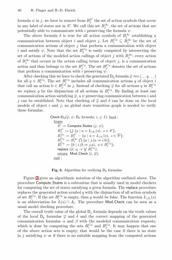
40 R. Pinger and H.-D. Ehrich
formula ψ in j, we have to remove from BS′j the set of action symbols that occur
in any label of states not in S′. We call this set BAcj , the set of actions that are
potentially able to communicate with i preserving the formula ψ.The above formula δ is true for all action symbols of BAc
j establishing acommunication between object i and object j. Let BCa
j ⊆ BAcj be the set of
communication actions of object j that perform a communication with objecti and satisfy ψ. Note that the set BCa
j is easily computed by intersecting theset of actions of the modeled action callings of object j with BAc
j : every actionof BAc
j that occurs in the action calling terms of object j, is a communicationaction and thus belongs to the set BCa
j . The set BCaj denotes the set of actions
that perform a communication with i preserving ψ.After checking this we have to check the generated D0 formula ϕ⇔i.(. . . q . . . )
for all q ∈ BCai . The set BCa
i includes all communication actions q of object ithat call an action b ∈ BCa
j in j. Instead of checking ϕ for all actions q in BCai
we replace q by the disjunction of all actions in BCai . By finding at least one
communication action satisfying ϕ, a ψ preserving communication between i andj can be established. Note that checking of ϕ and δ can be done on the localmodels of object i and j; no global state transition graph is needed to verifythese formulae.
Check-D0(ϕ, ψ: D0 formula; i, j: I): bool ;beginS′ := Compute States (j, ψ);BS′
j :=⋃ {a | a = L|Ai
(s), s ∈ S′};BAc
j := BS′j − {a | a = L|Ai
(s), s ∈ S′};BCa
j := BAcj
⋂ {a | j.(a ⇒ i.b)};BCa
i := {b | i.(b ⇒ j.a), a ∈ BCaj };
replace (ϕ, q → ∨BCa
i );return Mod Check (i, ϕ);
end ;
Fig. 3. Algorithm for verifying D0 formulae
Figure 3 gives an algorithmic notation of the algorithm outlined above. Theprocedure Compute States is a subroutine that is usually used in model checkersfor computing the set of states satisfying a given formula. The replace procedurereplaces the generated action symbol q with the disjunction of all action symbolsof set BCa
i . If the set BCai is empty, then q would be false. The function L|Ai
(s)is an abbreviation for L(s) ∩ Ai. The procedure Mod Check can be seen as ausual model checking procedure.
The overall truth value of the global D1 formula depends on the truth valuesof the local D0 formulae ϕ and δ and the correct mapping of the generatedcommunication formulae α and β with the modeled communication requests,which is done by computing the sets BCa
i and BCaj . It may happen that one
of the above action sets is empty; that would be the case if there is no statein j satisfying ψ or if there is no suitable mapping from the computed actions
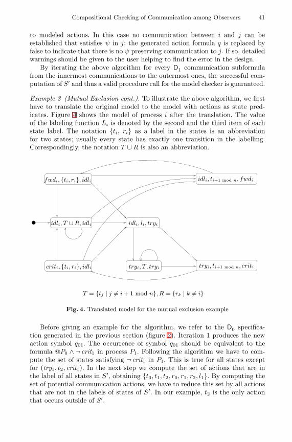
Compositional Checking of Communication among Observers 41
to modeled actions. In this case no communication between i and j can beestablished that satisfies ψ in j; the generated action formula q is replaced byfalse to indicate that there is no ψ preserving communication to j. If so, detailedwarnings should be given to the user helping to find the error in the design.
By iterating the above algorithm for every D1 communication subformulafrom the innermost communications to the outermost ones, the successful com-putation of S′ and thus a valid procedure call for the model checker is guaranteed.
Example 3 (Mutual Exclusion cont.). To illustrate the above algorithm, we firsthave to translate the original model to the model with actions as state pred-icates. Figure 4 shows the model of process i after the translation. The valueof the labeling function Li is denoted by the second and the third item of eachstate label. The notation {ti, ri} as a label in the states is an abbreviationfor two states; usually every state has exactly one transition in the labelling.Correspondingly, the notation T ∪R is also an abbreviation.
fwdi, {ti, ri}, idli
idli, T ∪R, idli
tryi, ti+1 mod n, criti
idli, ti+1 mod n, fwdi
tryi, T, tryi
T = {tj | j 6= i+ 1 mod n}, R = {rk | k 6= i}
idli, li, tryi
criti, {ti, ri}, idli
Fig. 4. Translated model for the mutual exclusion example
Before giving an example for the algorithm, we refer to the D0 specifica-tion generated in the previous section (figure 2). Iteration 1 produces the newaction symbol q01. The occurrence of symbol q01 should be equivalent to theformula @P0 ∧ ¬ crit1 in process P1. Following the algorithm we have to com-pute the set of states satisfying ¬ crit1 in P1. This is true for all states exceptfor (try1, t2, crit1). In the next step we compute the set of actions that are inthe label of all states in S′, obtaining {t0, t1, t2, r0, r1, r2, l1}. By computing theset of potential communication actions, we have to reduce this set by all actionsthat are not in the labels of states of S′. In our example, t2 is the only actionthat occurs outside of S′.
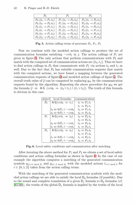
42 R. Pinger and H.-D. Ehrich
P0 P1 P2
P0.(t0 → P1.t0) P1.(t0 → P0.t0) P2.(t0 → P0.t0)P0.(t0 → P2.t0) P1.(t0 → P2.t0) P2.(t0 → P1.t0)P0.(t1 → P1.t1) P1.(t1 → P0.t1) P2.(t1 → P0.t1)P0.(t1 → P2.t1) P1.(t1 → P2.t1) P2.(t1 → P1.t1)P0.(t2 → P1.t2) P1.(t2 → P0.t2) P2.(t2 → P0.t2)P0.(t2 → P2.t2) P1.(t2 → P2.t2) P2.(t2 → P1.t2)
Fig. 5. Action calling terms of processes P0, P1, P2
Now we continue with the modeled action callings to produce the set ofcommunication formulae satisfying ¬ crit1 in j. The action callings of P1 aregiven in figure 5. The only actions that perform communications with P0 andmatch with the computed set of communication actions are {t0, t1}. Thus we haveto find action callings in P0 that communicate with P1 via actions t0 and t1 aswell. Due to the fact that P0 has suitable communication requests that matchwith the computed actions, we have found a mapping between the generatedcommunication requests of figure 2 and modeled action callings of figure 5. Theoverall truth value of ϕ can be computed by replacing q01 by the communicationrequests found by the algorithm. Repeating the above procedure for q02 we getthe formula ϕ ⇔ A G (crit0 ⇒ (t0 ∨ t1) ∧ (t1 ∨ t2)). The truth of this formulais obvious in this case.
object local formulae communicationP0 A G(crit0 ⇒ t1) t1 ⇒ P1.t1
t1 ⇒ P2.t1t2 ⇔ @P1 ∧ ¬ crit0 t2 ⇒ P1.t2t0 ⇔ @P2 ∧ ¬ crit0 t0 ⇒ P2.t0
P1 A G(crit1 ⇒ t2) t2 ⇒ P2.t2t2 ⇒ P0.t2
t0 ⇔ @P2 ∧ ¬ crit1 t0 ⇒ P2.t0t1 ⇔ @P0 ∧ ¬ crit1 t1 ⇒ P0.t1
P2 A G(crit2 ⇒ t0) t0 ⇒ P0.t0t0 ⇒ P1.t0
t1 ⇔ @P0 ∧ ¬ crit2 t1 ⇒ P0.t1t2 ⇔ @P1 ∧ ¬ crit2 t2 ⇒ P1.t2
Fig. 6. Local safety conditions and communication after matching
After iterating the above method for P1 and P2 we obtain a set of local safetyconditions and action calling formulae as shown in figure 6. In the case of ourexample the algorithm computes a matching of the generated communicationsymbols qi(i+1 mod 3) and qi(i−1 mod 3) with the modeled actions ti+1 mod 3 fori ∈ {0, 1, 2} taken from the action calling terms.
With the matching of the generated communication symbols with the mod-eled action callings we are able to satisfy the local D0 formulae (if possible). Dueto the sound and complete translation of a given D1 formula to D0 formulae (cf.[EC00]), the truths of the global D1 formula is implied by the truths of the local
Compositional Checking of Communication among Observers 43
D0 formulae. Once we have found a matching satisfying the local D0 formulae,the global D1 formula is satisfied as well. Thus our reasoning from the local tothe global level is sound due to the soundness and completeness of the D1 to D0translation.
4 Concluding Remarks
The investigation of the idea presented in this paper is at its beginning, furtherstudy is necessary in order to explore how the idea can best be utilised in checkingobject system designs. For doing this, appropriate tool support in combinationwith existing model checkers is essential.
Although we introduce new communication conditions, the overall verifica-tion is promised to be very efficient. Due to the fact that the model checkingcomplexity grows linearly with the length of a given CTL-formula (cf. [CGP00]),the local model checking amount is increased linearly by introducing new com-munication conditions. Compared to the verification of global models, the extraeffort needed for checking newly introduced communication conditions on localmodels should be relatively small.
The technique described here has the limitation that we are able to dealwith direct communication only. Note that there must be a direct communica-tion between two components i and j, if e.g. i uses a communication subformulaof observer j. Systems using indirect or asynchronous communication can notbe verified directly: whereas indirect communication has to be split into its di-rect communication parts on the specification level, systems using asynchronouscommunication have to be transformed to synchronous ones. The transformationmight be done by using special buffer objects.
The original motivation for studying D1 and D0 and their translation wasto use them for modelling and specification [ECSD98]. D0 was chosen to de-scribe the semantics of the Troll language, which was developed along withan application project to design an information system for a laboratory in theGerman National Institute of Weights and Measures (PTB) in Braunschweig, cf.[HDK+97,GKK+98].
References
[AL93] Martin Abadi and Leslie Lamport. Composing Specifications. ACM Trans-actions on Programming Languages and Systems, 15(1):73–132, January1993.
[AL95] Martin Abadi and Leslie Lamport. Conjoining Specifications. ACM Trans-actions on Programming Languages and Systems, 17(3):507–534, 1995.
[CE81] Edmund M. Clarke and E. Allen Emerson. Design and Synthesis of Syn-chronization Skeletons Using Branching Time Temporal Logic. LectureNotes in Computer Science, 131:52–71, 1981.
[CGP00] Edmund M. Clarke, Orna Grumberg, and Doran A. Peled. Model Checking.MIT Press, 2000.
[CLM89] E. M. Clarke, D. E. Long, and K. L. McMillan. Compositional ModelChecking. In Proceedings fo the 4th Annual Symposium on Principles ofProgramming Languages, pages 343–362, 1989.
44 R. Pinger and H.-D. Ehrich
[DH97] G. Denker and P. Hartel. Troll – An Object Oriented Formal Methodfor Distributed Information System Design: Syntax and Pragmatics.Informatik-Bericht 97–03, Technische Universitat Braunschweig, 1997.
[dNV90] Rocco de Nicola and Frits Vaandrager. Action versus State based Logicsfor Transition Systems. In I. Guessarian, editor, Semantics of Concur-rency, volume 469 of Lecture Notes in Computer Science, pages 407–419,1990.
[dR97] Willem-Paul de Roever. The Need for Compositional Proof Systems: ASurvey. In Willem-Paul de Roever, Hans Langmaack, and Amir Pnueli, ed-itors, Compositionality: The Significant Difference, volume 1536 of LectureNotes in Computer Science, pages 1–22, September 1997.
[EC00] H.-D. Ehrich and C. Caleiro. Specifying communication in distributedinformation systems. Acta Informatica, 36 (Fasc. 8):591–616, 2000.
[ECSD98] H.-D. Ehrich, C. Caleiro, A. Sernadas, and G. Denker. Logics for Spec-ifying Concurrent Information Systems. In J. Chomicki and G. Saake,editors, Logics for Databases and Information Systems, pages 167–198.Kluwer Academic Publishers, 1998.
[EP00] H.-D. Ehrich and R. Pinger. Checking object systems via multiple ob-servers. In International ICSC Congress on Intelligent Systems & Appli-cations (ISA’2000), volume 1, pages 242–248. University of Wollongong,Australia, International Computer Science Convetions (ICSC), Canada,2000.
[FM95] Jose Luiz Fiadeiro and Tom Maibaum. Verifying for Reuse: Foundations ofObject-Oriented System Verification. In C. Hankin, I. Makie, and R. Na-garajan, editors, Theory and Formal Methods, pages 235–257. World Sci-entific Publishing Company, 1995.
[GKK+98] A. Grau, J. Kuster Filipe, M. Kowsari, S. Eckstein, R. Pinger, and H.-D.Ehrich. The Troll Approach to Conceptual Modelling: Syntax, Semanticsand Tools. In T.W. Ling, S. Ram, and M.L. Lee, editors, Proc. of the 17thInt. Conference on Conceptual Modeling (ER’98), Singapore, pages 277–290. Springer, LNCS 1507, November 1998.
[GL94] Orna Grumberg and David E. Long. Model Checking an Modular Ver-ification. ACM Transactions on Programming Languages and Systems,16(3):843–871, 1994.
[HDK+97] P. Hartel, G. Denker, M. Kowsari, M. Krone, and H.-D. Ehrich. Informa-tion systems modelling with Troll formal methods at work. In Informa-tion Systems, volume 22, pages 79–99, 1997.
[HR00] Michael R. A. Huth and Mark D. Ryan. Logic in Computer Science -Modelling and reasoning about systems. Cambridge University Press, 2000.
[Jos89] Bernhard Josko. Verifying the Correctness of AADL Modules using ModelChecking. In J. W. de Bakker, W. P. de Roever, and G. Rozenberg,editors, Stepwise Refinement of Distributed Systems, Models, Formalisms,Correctness, volume 430 of Lecture Notes in Computer Science, pages 386–400, 1989.
[MC81] Jayadev Misra and K. Mani Chandy. Proofs of Networks of Processes.IEEE Transactions on Software Engineering, SE-7(4):417–426, July 1981.
[Pnu85] Amir Pnueli. In Transition From Global to Modular Temporal Reasoningabout Programs. In Krzysztof R. Apt, editor, NATO ASI Series, volumeF13, 1985.
Combining Independent Specifications
Joy N. Reed1∗and Jane E. Sinclair2
1 Oxford Brookes University, Oxford, UKEmail: [email protected] Fax: +44 (0) 1865 483666
2 University of Warwick, Coventry, UKEmail: [email protected] Fax: +44 (0) 2476 573024
Abstract. We present a formal framework for characterising plug-in re-lationships between component specifications. A suitability requirementis defined based on the effect one component has on the other in terms ofdeadlock. Unlike monotonic operations such as parallel composition, notall such suitability requirements are preserved by refinement. Hence, wedefine the notion of a bicompositional relation between co-operating pro-cesses which is preserved by component-wise refinements. The approachis described in CSP using the failures semantic model. The aim is tounderpin a mixed-paradigm approach combining different specificationmethods, including state-based deductive formalisms such as ActionSystems, and event-based model checking formalisms such as CSP/FDR.The objective is to play to the strengths and overcome limitations of eachtechnique, by treating different system aspects with individual tools andnotations which are most appropriate.
1 Introduction
A formal method is a mathematically-based theory which is used to describeand reason about the behaviour of a computer system. Application of aformal method encompasses specification of the system in a chosen formalnotation, analysis and verification of key properties and stepwise refinementto a correct implementation. It is generally recognised that even partial use ofthese techniques during development can significantly increase the quality ofsoftware and hardware systems, with respect to correctness and maintainability.For example, the application of a general-purpose specification notation such asZ [Spi92] has been found to lead to the earlier discovery of design flaws. Formalmodelling and verification of small security protocols such as that by Lowe andRoscoe [LR97], Lowe [Low96] and Meadows [Mea94] has revealed previouslyunsuspected flaws in the operation of these protocols.
Various formal methods with different theoretical bases have been proposed.No one formalism is fully suitable for all aspects of industrial-sized applications,as we have illustrated by directly comparing strengths and weaknesses ofstate-based, deductive reasoning approaches and event-based, model checkingapproaches applied to a distributed mail system [RSG99] and general routing∗
This work was supported in part by the US Office of Naval Research
H. Hussmann (Ed.): FASE 2001, LNCS 2029, pp. 45–59, 2001.c© Springer-Verlag Berlin Heidelberg 2001
46 J.N. Reed and J.E. Sinclair
protocols [RSR99]. With a deductive reasoning approach, a specification givesan abstract description of the significant behaviour of the required system. Thisbehaviour can be verified for the defined implementation by proving the theoremswhich constitute the rules of refinement. With model checking, a specificationcorresponds to a formula or property which can be exhaustively evaluated on aspecific finite domain representing implementations. Deductive reasoning is moregeneral, but only partially automatable. Model checking is more limited but fullyautomatable. Our previous work [RSG99] shows that in addition to theoreticallimitations of a notation, its form leads towards specification of a certain styleand often with particular implicit assumptions.
Combining the different views can give a fuller picture, but the questionremains as to how this integration can best be achieved. Incorporating all aspectsinto one unified approach based around a particular formalism and tool set isa possibility, but this could result in additional complexity and obscurity forloosely coupled components. In contrast, our approach for combining differentformalisms is to relate their different system views in a way which allowsmeaningful and independent analysis, including stepwise development throughseparate refinement. Our long-term aim is to provide a formal underpinning forthis approach, so that certain state-based safety properties can be handled withstate-based techniques and tools, and event-based, liveness properties can behandled with model checkers. In this paper we identify relationships betweenloosely-coupled components which ensure the soundness of component-wiserefinement. The notation used is CSP [Hoa85] which is particularly convenientfor event-based specification and model checking. We indicate how this could becombined with a state-based notation such as Action Systems [BKS83], usingtheir common failures divergences semantics.
2 Interoperating Components: An Example
In an environment of distributed systems it is increasingly the case thatany transaction requires the interoperation of a chain of components andservices which combine to produce (hopefully) the desired result. Variouscomponents may be selected as “off the shelf” products to plug-in to ourparticular application. Some of these services may be beyond our control, butwe still have expectations of harmonious behaviour. The correct operation ofan application depends not only on the integrity of its own functions, but alsoon the components with which it interacts and on the interaction itself. Whilstformal verification of the entire system is not practical, there may be certaincrucial interactions which warrant the extra care provided by formalism. Somecomponents, such as security services, may have been verified in their own rightand come with assurance of their behaviour. We are interested characterisingsuch assurances.
As an example, we consider a specification for a secure database whichanswers requests for information from its subscription customers. The databaseand many of its operations can be described in a natural way using a state-based
Combining Independent Specifications 47
approach. The system must also take into account the need for appropriatesecurity controls. A number of useful algorithms (and implementations of these)already exist for such things, so our top level specification states its basicrequirements and relies on these being satisfied by a suitable plug-in component,which as a separate concern may range from providing only simple confidentialitythrough to providing additional authentication and integrity. The top levelspecification simply needs to know that a task will be performed (such as, acommon session key being distributed to both database and client), with no needto place constraints on the values it requires. We wish to treat the functionalproperties of the subscription database and the security protocol as separateunits which can be further developed and verified separately in different ways asappropriate.
Using Action Systems, which describe both system state and the interactionof events, we can specify a suitable top-level for the database. Conditions suchas clearance to access data can be succinctly captured and verified in this way.In contrast, other tasks such as developing and verifying a suitable key exchangeprotocol between the parties is not best-suited to such a notation. In fact, suitableprotocols have already been described and verified in other ways, notably usingCSP. We wish to “hand over” from the Action Systems to CSP for these. Weconsider below how this hand over can be achieved and why something morethan the usual parallel composition is desirable.
3 Combining Notations in Practice
The trace/failures/divergences semantics models of CSP described in the nextsection provide a unifying semantics for Action Systems and CSP. Although acommon semantics provides a theoretical link, it does not immediately solve theproblems of using the notations together. The specifier is concerned with theeffects of combining different parts of a specification and the constraints placedon each part by others. Translating the specifications to common ground is apossibility but, in general, prohibitively cumbersome. This has led to on-goingresearch for specific areas where manageable proof conditions can be generated.Schneider and Treharne [TS99,TS] have worked with B and CSP defining a CSPdriver to control operations described in B. Butler [But99] defines a generalapproach to combining B and CSP which merges CSP into B through translation.Both approaches provide useful insights into how the two notations can bebrought together, yet neither are sufficient for our purpose. Like Schneider andTreharne, we wish to maintain the separation of notations. Like Butler, we wishto allow each to have a more general use. Our aim is to provide a framework inwhich “suitable” components can be “plugged” together and refined separately.In this paper, we explore a notion of “suitable plug-in”.
The parallel composition operator can be used to combine CSP processesand/or Action Systems. So if P is an Action Systems specification for someaspect or component of a system, and Q is a CSP specification for another aspector component, then P ‖ Q represents their parallel combination with behaviour
48 J.N. Reed and J.E. Sinclair
well-defined (although possibly not easily understood), and any safety (that is,trace) property of either P or Q with respect to their common actions/events ispreserved by P ‖ Q . In contrast to safety properties, liveness properties are notpreserved by the ‖ operator, as illustrated by Example 2 below. If Q is a plug-infor P then at the very least we require that it should respond in a way suitablefor P and not cause P to deadlock when they are run in parallel.
We formulate our suitability requirements using CSP semantics shared byboth Action Systems and CSP. The issue of specialising to the different notationsis returned to in later sections. We first give a brief introduction to CSP. Anoverview of CSP syntax and the failures model is given in the Appendix.
4 CSP and FDR
CSP [Hoa85] models a system as a process which interacts with its environmentby means of atomic events. Communication is synchronous: an event takes placeprecisely when both process and environment agree on its occurrence. This ratherthan assignments to shared variables is the fundamental means of interactionbetween agents. CSP comprises a process-algebraic programming language.A related series of semantic models capture different aspects of observablebehaviours of processes: traces, failures and divergences. The simplest semanticmodel is the traces model which characterises a process as an alphabet α(P) ofevents, together with the set of all finite traces, traces(P), it can perform. Thetraces model is sufficient for reasoning about safety properties. In the failuresmodel [BHR84] a process P is modelled as a set of failures. A failure is a pair(s,X ) for s a finite trace of events of α(P), and X a subset of events of α(P);(s,X ) ∈ failures(P) means that P may engage in the sequence s and thenrefuse all of the events in X . The set X is called a refusal. The failures modelallows reasoning about certain liveness properties. More complex models suchas failures/divergences[BR85] and timed failures/divergences [RR99] have morestructures allowing finer distinctions to support more powerful reasoning. Tracesand failures are also defined for Action Systems [Mor90,WM90,But92] providinga semantic link to CSP. For the rest of this paper, we restrict our discussion tothe failures model.
We say that a process P is a refinement of process S (S v P) if any possiblebehaviour of P is also a possible behaviour of S :
failures(P) ⊆ failures(S )
which tells us that any trace of P is a trace of S , and P can refuse an event xafter engaging in trace s, only if S can refuse x after engaging in s.
Intuitively, suppose S (for “specification”) is a process for which allbehaviours it permits are in some sense acceptable. If P refines S , then anybehaviour of P is as acceptable as any behaviour of S . S can represent anidealised model of a system’s behaviour, or an abstract property correspondingto a correctness constraint, such as deadlock or livelock freedom. A wide range ofcorrectness conditions can be encoded as refinement checks between processes.Mechanical refinement checking is provided by Formal Systems’ model checker,FDR [For].
Combining Independent Specifications 49
5 The Relationship between Components
We view our top-level specification as structured as a set of interoperablecomponents which act in parallel. In particular, we are interested in components,such as the key exchange protocol which may be called upon to perform sometask as part of a larger system. Although parallel composition can be used tocombine any two processes, we would not regard every process as a suitablefulfilment of the requirements of the larger system. It is this additional conceptof suitability that we wish to capture.
Example 1. Suppose process P makes a request (event a) to receive two keys(events k1 and k2). P does not care in which order the keys are obtained.
P = (a → k1 → k2 → P)2(a → k2 → k1 → P)
Process Q is a component which is chosen to distribute keys, and this happensto be specified as responding first with k1 and then with k2.
Q = a → k1 → k2 → Q
It is expected that establishing the keys as specified by Q will be achieved bysome more detailed algorithm which, with internal details hidden, refines Q .We regard Q as a plug-in to P , since their joint behaviour expressed by P ‖ Qconforms to one of the possibilities allowed by P . Clearly not every process whichreturns keys should be regarded as a plug-in to P . For example, consider R:
R = a → k1 → k1 → R
This time R does not interact with Q in a desirable way since it does not havean acceptable pattern of response, and the result is deadlock at the third step.
In general, Q will be suitable to plug in to P if it is prepared to co-operatewith the pattern set out by P . If P allows an (external) choice then Q mayresolve it. If P ’s actions are nondeterministic, Q must be prepared to deal witheach possibility. This can be characterised in terms of deadlock: Q must notcause P to deadlock when they are run in parallel.
Further problems are encountered when considering refinement. In general,we expect that whenever a specification is good enough for some purpose, thenso is any refinement. However, Example 2 shows that if we are dealing with plug-in relationships between component processes which ensure that their parallelcombination describes desirable properties of our system, it does not follow thatcomponent-wise refinements are suitable according to the same criteria. That is,for a relation ρ on processes, if PρQ , P v P ′ and Q v Q ′, then by monotonicitywe know that P ′ ‖ Q ′ v P ‖ Q – but is not necessarily true that P ′ρQ ′.
Example 2. Suppose P and Q are both defined as follows:
P = (x → P) u STOPQ = (x → Q) u STOP
50 J.N. Reed and J.E. Sinclair
We observe that P and Q satisfy the relationship:
P v P ‖ Q
(this relationship might appear desirable since it ensures that Q cannot causeany deadlock not also allowed by P). P and Q satisfy this property, but notrefinements:
P ′ = x → P ′ Q ′ = STOP
Clearly P v P ′ and Q v Q ′ and yet P ′ 6v P ′ ‖ Q ′.
Example 2 shows that potential candidates for describing suitable plug-in rela-tionships between components may not be preserved by refinement. This wouldbe disastrous from the point of view of building systems with independentlydeveloped components. In this paper we concentrate on patterns of interactionbetween two processes P and Q which, as in Example 1 above, behave like asimple remote procedure call from P to Q . We regard Q as a plug-in to Pif Q responds in a way which does not increase the opportunities for deadlock.Furthermore, we regard Q to be a suitable plug-in to P if for any component-wiserefinements Q ′ and P ′, Q ′ is a plugin to P ′. In the rest of the paper, weinvestigate how to formalise these notions. We first define a general property ofrelations which is useful for capturing the notion that refinements of processesinherit their parents’ relationship.
Definition 1 (Bicompositional Relations). Let φ and ρ each be a relation onX . We say that φ is bicompositional with ρ iff for xφy , xρx ′, yρy ′, then x ′φy ′
Example 3. Let R be the relation < and S the relation which holds between xand y iff y = x + 1. Then R is bicompositional with S . This example also showsthat the property is not symmetric since S is not bicompositional with R. Inaddition, it is neither reflexive nor transitive.
In general, relations are not bicompositional with themselves, for example, therelation < is not bicompositional with <. Equivalence relations are bicompo-sitional with themselves, though not in general bicompositional with arbitraryother relations.
6 Bicompositional Refinements
We can capture the notion that a given relationship φ between cooperatingspecifications is inherited by refinements by requiring φ to be bicompositionalwith v. We say that φ is bicompositional whenever
PφQ ∧ P v P ′ ∧ Q v Q ′ ⇒ P ′φQ ′
We can make the relationship given in Example 2 bicompositional by requiringnot only that P v P ‖ Q but also that P is deterministic. However this does
Combining Independent Specifications 51
not offer a general solution to this refinement paradox; it defeats the purpose ofrefinement since all refinements of P must then in fact be equal to P . We mightinstead insist that P and Q always operate together in a deadlock free fashion.We cannot ensure this by simply requiring that each of P and Q is deadlockfree, as illustrated by P = uT
x → P and Q = uTx → Q . P and Q are each
deadlock free since each is willing to do some event of T , but P ‖ Q can deadlockwhenever they do not agree on their chosen events. However, if we also requireP ‖ Q to be deadlock free as well, Example 4 below ensures that any refinementsP ′ and Q ′ inherit their parents’ good behaviour and so cannot deadlock whenthey themselves are run in parallel.
Example 4. Processes P and Q are mutually deadlock free iff each of P and Qis deadlock free, and their parallel composition is deadlock free. Mutual deadlockfreedom is bicompositional.
Proof. A process is deadlock free iff it refines the process DF which is alwayswilling to do something in its alphabet Σ:
DF = uΣ
a → DF
Let DF v P , DF v Q , and DF v P ‖ Q . Also let P v P ′ and Q v Q ′. Then itfollows by monotonicity that DF v P ′, DF v Q ′, and P ‖ Q v P ′ ‖ Q ′, andDF v P ′ ‖ Q ′. utMutual deadlock freedom, though bicompositional, is too strong a property torequire of cooperating applications Q and P for which Q responds to a one-timeinvocation from P . For example, Q may be a set-up process which P calls onceand only once. Thus, P ‖ Q will properly deadlock on their joint alphabet afterQ finishes its work, whilst P carries on with other events not requiring anyparticipation from Q . Or Q behaves as a remote procedure call to P , whichmay acceptably never invoke any services provided by Q . Indeed, we may wishto allow P itself to deadlock. Let us imagine that we want P to trigger Qby handing over some parameters, which Q processes, subsequently returningresults back to P . P is in control, and may invoke Q arbitrarily, including never;Q is always required to be ready, and is willing to be invoked forever. Whatis required is a bicompositional relation between P and Q which implies thattheir parallel combination deadlocks on the intersection of their joint alphabetJ only where P chooses. Then, if we refine P and Q with P ′ and Q ′, the parallelcombination of P ′ and Q ′ deadlocks on the intersection of their joint alphabetonly where P ′ chooses.
We begin with some notation, then define a relationship which we regard ascharacterising the notion that one process is as live as another. We illustrate thatthis relationship is not in general preserved by refinement, and require that sucha relation qualify as a plug-in only if it is preserved by refinement. We finallydefine some stronger bicompositional relations which qualify as plug-ins.Notation. For process P and set J of events, α(P) represents the alphabet ofP , and traces(P) � J represents the set of traces of P stripped of all events notin J , and failures(P) � J has both traces and refusals of P stripped of any events
52 J.N. Reed and J.E. Sinclair
not in J . We regard Q as a plug-in to P iff Q is allowed to refuse to do all of Jafter trace S (thus causing deadlock) only if P can as well:
Definition 2. Q is as live as P , for αP ∩ αQ = J means
(s, J ) ∈ failures(P ‖ Q) � J ⇒ (s, J ) ∈ failures(P) � J
This relation constrains Q to deadlock only when P might, and in particular, ifP is deadlock free, then P ‖ Q is deadlock free. But it is not bicompositional. Forthe processes defined below, Q is as live as P (which both behave chaotically),but for the refinements, Q ′ is not as live as P ′.
Example 5. P = (2Rr → P)u STOP
P ′ = 2Rr → P
Q = (uRr → Q)u STOP
Q ′ = STOP
We characterise a plug-in relationship:
Definition 3. Q plugs-in P , means
1. Q is as live as P, and2. for all P ′, Q ′, if P v P ′ and Q v Q ′, then Q ′ is as live as P ′.
We now identify bicompositional relations between P and Q which imply thatQ plugs-in to P . The first definition characterises interactions between processesP and Q whereby whenever P is ready to output a value x on the channel T toQ , then Q is ready to receive it.
Definition 4. Q listens on T to P , for T ⊆ αP ∩ αQ means
x ∈ T ∧ s a 〈x 〉 ∈ traces(P) � J ∧ s ∈ traces(Q) � J
⇒ (s, {x}) /∈ failures(Q) � J
Theorem 1. The relation listens on T to is bicompositional.
Proof. Assume
(1)P v P ′ and Q v Q ′
(2) x ∈ T ∧ s a 〈x 〉 ∈ traces(P) � J ∧ s ∈ traces(Q) � J
⇒ (s, {x}) /∈ failures(Q) � J
We must show
x ∈ T ∧ s a 〈x 〉 ∈ traces(P ′) � J ∧ s ∈ traces(Q ′) � J
⇒ (s, {x}) /∈ failures(Q ′) � J
Assume the hypothesis of the implication. By (1) s a 〈x 〉 ∈ traces(P) � J ands ∈ traces(Q) � J . Thus by (2), (s, {x}) /∈ failures(Q) � J , and again by (1)(s, {x}) /∈ failures(Q ′) � J . ut
Combining Independent Specifications 53
We next define a bicompositional property which characterises a process Qoutputting along channel R whenever P wants. We do not want to overlyconstrain Q , that is, Q should be allowed to deadlock on their joint alphabetwhenever P is willing to do so. If we require that P either must be prepared toaccept any answer communicated by Q , or possibly deadlock – but not bothsimultaneously – then the relation is bicompositional. The following definitioncharacterises processes P and Q whereby whenever P is ready to receive inputfrom Q , Q is ready to send it. It says that whenever P is ready to receive anyvalue of R – there is an obligation on P to be ready to receive any other valueas well, and there is an obligation on Q be ready to output something.
Definition 5. Q answers on R to P, for R ⊆ αP ∩ αQ = J means
x ∈ R ∧ y ∈ R ∧ s a 〈x 〉 ∈ traces(P) � J ∧ s ∈ traces(Q) � J
⇒ (s,R) /∈ failures(Q) � J ∧ (s, {y}) /∈ failures(P) � J
Theorem 2. The relation answers on R to is bicompositional.
Proof. Assume
(1)P v P ′ and Q v Q ′
(2) x ∈ R ∧ y ∈ R ∧ s a 〈x 〉 ∈ traces(P) � J ∧ s ∈ traces(Q) � J
⇒ (s,R) /∈ failures(Q) � J ∧ (s, {y}) /∈ failures(P) � J
Let
x ∈ R ∧ y ∈ R ∧ s a 〈x 〉 ∈ traces(P ′) � J ∧ s ∈ traces(Q ′) � J
We must show
(s,R) /∈ failures(Q ′) � J ∧ (s, {y}) /∈ failures(P ′) � J
Assume (s,R) ∈ failures(Q ′) � J . Then by (1), (s,R) ∈ failures(Q) � J , andfurthermore, sa〈x 〉 ∈ traces(P) � J and s ∈ traces(Q) � J . Thus by (2), (s,R) /∈failures(Q) � J , and this contradiction establishes that (s,R) /∈ failures(Q ′) � J .Assume (s, {y}) ∈ failures(P ′) � J . Again by (1), (s, {y}) ∈ failures(P) � J , butthis contradicts (2) thereby establishing the theorem. ut
The next theorem establishes that for processes P and Q synchronising onthe intersection of their alphabets, if Q listens to P , and Q answers P , then Qplugs-in to P .
Theorem 3. If Q listens on T to P and Q answers on R for T ∪ R = α(P) ∩α(Q) = J , then (s, J ) ∈ failures(P ‖ Q) � J only if (s, J ) ∈ failures(P) � J .
54 J.N. Reed and J.E. Sinclair
Proof. Assume (s, J ) ∈ failures(P ‖ Q) � J . By failures model definition for theparallel operator (see Appendix), for some refusal sets X ,Y , X ∪ Y = J , s ∈traces(P) � J and s ∈ traces(Q) � J and (s,X ) ∈ failures(P) � J , and (s,Y ) ∈failures(Q) � J . Assume (s, J ) /∈ failures(P) � J . Then X 6= J , and since Pcannot refuse all of J there must exist an x /∈ X such that sa〈x 〉 ∈ traces(P) � J .There are two cases : x ∈ T or x ∈ R. Case 1. Assume x ∈ T . Since Q listenson T to P , (s, {x}) /∈ failures(Q) � J . Since (s,Y ) ∈ failures(Q) � J , then byfailures axiom (M3) which says that any subset of a refusal set is itself a refusalset, it follows that x /∈ Y . This contradicts that X ∪ Y = J , and case is proved.Case 2. Assume x ∈ R. Since Q answers on R to P , (s,R) /∈ failures(Q) � J .Furthermore, (s, {y}) /∈ failures(P) � J for any y ∈ R. By (M3), it follows thatX ∩ R = {}. Hence R ⊆ Y and again by (M3), (s,R) ∈ failures(Q) � J . Thiscontradiction proves the case and the theorem. ut
Summary. We have identified a notion of one process Q being as live asanother process P , whereby we mean that Q introduces no more possibilitiesfor deadlock than P . The examples show that there is a conflict betweenallowing nondeterminism in specifications for P and Q , and preserving thisliveness relationship under refinement. We have identified a notion of a plug-inrelationship between P and Q , which requires that this liveness relationship ispreserved by component-wise refinements.
The bicompositional listening and answering relations between P and Q de-fined above ensure that Q acts as a suitable plug-in to P . P nondeterministicallytriggers Q , which returns results back to P . If Q listens on T to P , and Q answerson R to P , for α(P) ∩ α(Q) = T ∪ R then Q plugs-in to P , and if P v P ′
and Q v Q ′ then Q ′ plugs-in t P . Thus we can confidently refine P and Qseparately, knowing that refinements cooperate as desired.
7 Using the Definitions
The following small examples illustrate the use of the properties defined above.Components are defined using CSP.
Example 6. In the first case, P is a process which places a request with eitherevent a1 or event a2 (chosen nondeterministically). Q is willing to accept eitherand provide an acceptable response, hence Q acts as a suitable plug-in to P .
P = (a1 → r− > P) u (a2 → r → P)
Q = (a1 → r → Q) 2 (a2 → r → Q)
Q listens on {a1, a2} to P – because Q has the same traces as P and refusesneither a1 nor a2 at any point where P might engage in them.Q answers on {r} to P – because Q is willing to provide a response wheneverP expects one.
Combining Independent Specifications 55
Example 7. We have a different situation if Q is able to deal with one of thepossible requests only, rendering it an unsuitable plug-in to P .
P = (a1 → r → P) u (a2 → r → P) Q = (a1 → r → Q)
Q does not listen on {a1, a2} to P – because 〈a2〉 is a trace of P but(〈〉, {a2}) is a failure of Q .
Example 8. The listening and answering relations are not inverses:
P = (a → P) u STOP Q = (a → Q)
Q listens on {a} to P – because Q is willing to provide a response wheneverP might expect one.P does not answer on {a} to Q – because 〈a〉 is a trace of Q but (〈〉, {a})is a failure of P .
Example 9. Here P requests a key which is subsequently supplied by Q . Q selectsthe value for the key which it outputs to P on channel SupplyKey . P is preparedto input any value on SupplyKey , hence, Q acts as a suitable plug-in to P .
P = RequestKey → SupplyKey?k : KEY → PQ = RequestKey → u
k :KEY(SupplyKey !k → Q)
Q listens on {RequestKey} to P – because Q is always ready to accept a keyrequest whenever P issues one.Q answers on {k : KEY | SupplyKey .k} to P – because whenever P wants akey as input, it accepts any key offered, and Q is ready to offer one.
8 Using CSP Plug-Ins with Action Systems
The listening and answering relations we have identified are not completelygeneral, but do typify a number of client-server behaviours. Their formulations inCSP failures models makes them meaningful for both Action Systems and CSP,providing a means of ensuring that two processes can be separately developed,whilst maintaining integrity of combined behaviour.
What remains is to to use the formal connection between the two notations toverify the properties for individually specified components. We are investigatingpractical approaches for verifying these properties for certain classes of “loosely-coupled” components illustrated by our secure database example.
For example, suppose a CSP specification for a key exchange protocoldescribes a process which is always willing to accept a request as input, andsubsequently distribute a common key to the server and user, in nondeterministicorder. It should be deliberately abstract to allow for a variety of specific keydistribution protocols. This is to be viewed as a “minimum specification” of thekey exchange to be refined and verified as a separate unit. We want to plug
56 J.N. Reed and J.E. Sinclair
this in to the Action System and show that the behaviour allowed by the CSPplug-in is acceptable to the database specification.
One of the advantages of relating components using bicompositional proper-ties is that different components can be refined independently and the propertiesare guaranteed to hold between all refinements. There are various aspects of theCSP specification which we might want to further develop through refinement.One is to unfold specific details of a chosen key exchange protocol by describingan intended implementation, or an off-the-shelf component. This might introducea trusted key server together with a prescribed sequence of events required bythe protocol between user clients and the database server. We can verify that theimplementation is valid by checking that, with additional events hidden, it is arefinement of Q , thus establishing that the chosen protocol behaves as expected.
A significant advantage of treating the security protocol as a suitable CSPplug-in is that we can naturally specify event-based behaviour and check relevantproperties automatically using the FDR model checker, perhaps with variousinduction techniques (for example [CR99]) and data independence techniques(for example [Ros98,RL96]) for transcending bounded state. A significantdisadvantage of using Action Systems for such aspects is that properly specifyingallowable sequences of actions is very awkward. Another reason for refiningthe CSP specification is that we might want to analyse behaviour of a chosenprotocol with respect to security, for example, robustness against deliberateor inadvertent attacks by intruders. For example, Lowe and Roscoe [LR97]discover potential security flaws with the TMN key exchange protocol, revealedby counter examples provided by FDR showing that attackers could performoperations specifically disallowed by the CSP specification.
9 Conclusion
The work described in this paper is the first step towards a general frameworkfor describing and verifying the suitability of separate components workingtogether to form an integrated system. Components are likely to be developedseparately, using different notations and techniques. It is also likely thatpreviously-developed components would be incorporated, in which case thecomponent should provide an abstract specification (or specifications) as aminimum guarantee of its behaviour. In this way, a formal framework can beprovided for larger systems created from a variety of loosely coupled subsystems,using off-the-shelf components where possible.
We have used relational constraints to characterise our notion of minimumrequirements for a plug-in component: it must operate under the control ofthe main component in that the combination deadlocks only at the behest ofthe main. The approach also applies to independent processes which are notin a master-slave relationship but which are co-operating to achieve a one-offtask. There may be other properties which would be useful to incorporate,perhaps tailored to the purposes of a specific system, but the notion of plug-incomponents which operate in accordance with the demands of a requestingmodule seems to be a generally useful one. Identifying bicompositionalitybetween specifications underlines the fact that not all desirable relationships
Combining Independent Specifications 57
between components would be preserved by refinement. Working with a propertywhich is not bicompositional makes verification extremely difficult: either theproperty is proved at an early stage and continued effort is needed to checkthat the property is maintained as the system is refined, or the propertyis not checked till a later stage when proof is often more difficult and mayreveal errors stemming from an early stage of development. The “listening” and“answering” properties provide sufficient conditions ensuring a bicompositionalplug-in relationship. Another feature of these properties is that, unlike theformulation of the ”as live as” relation, there is no need to directly deal with theparallel system of the two components. However, proving trace requirements isstill not completely straightforward and efficient proof techniques are a topic ofon-going research.
As sufficient conditions, we are aware that the properties given here rule outsome cases which might otherwise be considered acceptable and that variationson the conditions might be devised to improve the situation. Other variationsmay be suitable in different circumstances. Further, there may be other usefulparadigms characterising processes which could place constraints on input, suchas insisting on receiving fresh keys. This is another area which we are continuingto develop. It is perhaps worth noting that in formulating bicompositionalproperties we encounter a difficulty similar to that of noninterference propertiesin security. Many different variants are possible and the effects are not alwaysapparent until pathological examples are examined.
Another guiding principle has been the need to support different notations.The case study from which this work arose describes a secure database describedusing Action Systems which uses plug-in components for security services suchas key exchange. The properties we have described are suitable for dealingwith combinations of both CSP processes and Action Systems since traces andfailures are defined for both. This allows both state-based and event-orientedspecifications to be used for parts of the system to which they are best-suited andcombined in a loosely-coupled manner. The approach is also applicable to othernotations for which a traces/failures interpretation can be given. Again, the factthat the parallel system does not have to be calculated is an advantage. However,the identification of sub-traces within each component is still a significant taskwhich forms part of the ongoing investigations referred to above.
As referred to in Section 3, work combining CSP with B is being undertakenby Butler [But99] and Treharne and Schneider [TS99,TS]. The main focusof these approaches has been to use CSP as a convenient way to specifyconstraints on the sequencing of, i.e., controlling the state-based actions. Wetake a different perspective, wishing to allow combinations of state-based andevent-based components with either being designated as being “in control” asappropriate. However, the techniques developed for these approaches in whichloop control requirements are “unwound” to give a set of verification conditionsmay be useful in establishing more easily provable conditions for our approach.
In common with Butler, Treharne and Schneider, our aim is to containinherent problems of scale in applying formal techniques to large applications.The goal of a great deal of current research is to combine different formalapproaches in order to treat different aspects of a given system. There is a
58 J.N. Reed and J.E. Sinclair
danger that combining techniques for a particular system creates prohibitivecomplexity. Our aim is to divide and conquer potential complexity by structuringspecifications early in the development process, so that independent analysiscan be effectively performed. Finally we note that our techniques are formulatedusing a traces/failures approach, but the concepts which we have identified aregenerally applicable to other formal and semi-formal specification techniques.
Acknowledgement. The authors would like to thank Mike Reed for hisvaluable discussions about various finer points of CSP semantics.
Appendix. A Taste of CSP
The CSP language is a means of describing components of systems, processes whoseexternal actions are the communication or refusal of instantaneous atomic events. Allthe participants in an event must agree on its performance. We give a selection of CSPalgebraic operators for constructing processes.
STOP the simplest CSP process; it never engages in any action, never terminates.a → P is the most basic program constructor. It waits to perform the event a and after
this has occurred it behaves as process P . The same notation is used for outputs( c!v → P ) and inputs (c?x → P(x ) ) of values on named channels.
P uQ is nondeterministic or internal choice. It may behave as P or Q arbitrarily.
P 2Q is external or deterministic choice. It first offers the initial actions of both Pand Q to its environment. Its subsequent behaviour is like P if the initial actionchosen was possible only for P , and similarly for Q . If P and Q have common initialactions, its subsequent behaviour is nondeterministic (like u). A deterministic
choice between STOP and another process, STOP 2P is identical to P .P ‖ Q is parallel (concurrent) composition. P and Q evolve separately, but events in
the intersection of their alphabets occur only when P and Q agree (i.e. synchronise)to perform them. (We use this restricted form of the parallel operator. The moregeneral form allows processes to selectively synchronise on events.)
P ||| Q represents the interleaved parallel composition. P and Q evolve separately,and do not synchronise on their events.
Failures Model. The set of failures F satisfies the following axioms [BHR84].
(〈〉, {}) ∈ F (M1)(s a t) ∈ F ⇒ (s, {}) ∈ F (M2)(s,X ) ∈ F ∧ Y ⊆ X ⇒ (s,Y ) ∈ F (M3)(s,X ) ∈ F ∧ (∀ c ∈ Y ⊆ α(P) • ((s a 〈c〉, {}) /∈ F ⇒ (s,X ∪ Y ) ∈ F (M4)
To illustrate how CSP operations are defined with failures semantics, we give thefailures for the parallel operator. We take the semantic view of having individualalphabets for each process [Hoa85] here to simplify the use of the parallel operator.
F [[P ‖ Q ]] = {(s,X ∪ Y ) | x ∈ s ⇒ x ∈ α(P) ∪ α(Q) ∧(s � α(P),X ) ∈ F [[P ]] ∧(s � α(Q),X ) ∈ F [[Q ]]}
Combining Independent Specifications 59
References
[BHR84] S.D. Brookes, C.A.R. Hoare, and A.W. Roscoe. A theory of communicatingsequential processes. JACM, 31:560–599, 1984.
[BKS83] R.J.R. Back and R. Kurki-Suonio. Decentralisation of process nets withcentralised control. In 2nd ACM SIGACT-SIGOPS Symposium on Principlesof Distributed Computing, pages 131–142, 1983.
[BR85] S.D. Brookes and A.W. Roscoe. An improved failures model for communi-cating sequential processes. In Proc. Pittsburgh Seminar on Concurrency.Springer, 1985.
[But92] M.J. Butler. A CSP Approach to Action Systems. DPhil thesis, Universityof Oxford, 1992.
[But99] M.J. Butler. csp2b: A practical approach to combining CSP and B. InJ. Woodcock J. Davies, J.M. Wing, editor, FM99 World Congress. SpringerVerlag, 1999.
[CR99] Sadie Creese and Joy Reed. Verifying end-to-end protocols using inductionwith CSP/FDR. In Proc. of IPPS/SPDP Workshop on Parallel andDistributed Processing, LNCS 1586, Lisbon, Portugal, 1999. Springer.
[For] Formal Systems (Europe) Ltd. Failures Divergence Refinement. User Manualand Tutorial, version 2.11.
[Hoa85] C.A.R. Hoare. Communicating Sequential Processes. Prentice Hall, 1985.[Low96] Gavin Lowe. Breaking and fixing the Needham-Schroeder public-key protocol
using FDR. In Proc. of TACAS, volume 1055 of LNCS. Springer, 1996.[LR97] G. Lowe and A.W. Roscoe. Using CSP to detect errors in the TMN protocol.
IEEE Trans. Soft. Eng., 23(10), 1997.[Mea94] C. Meadows. The NRL protocol analyzer: An overview. J. Logic Program-
ming, 19,20, 1994.[Mor90] C.C. Morgan. Of wp and CSP. In D. Gries W.H.J. Feijen, A.G.M.
van Gasteren and J. Misra, editors, Beauty is our business: a birthday saluteto Edsger W. Dijkstra. Springer-Verlag, 1990.
[RL96] A.W. Roscoe and R.S. Lazic. Using logical relations for automatedverification of data-independent CSP. In Oxford Workshop on AutomatedFormal Methods ENTCS, Oxford, UK, 1996.
[Ros98] A.W. Roscoe. Theory and Practice of Concurrency. Prentice Hall, 1998.[RR99] G.M. Reed and A.W. Roscoe. The timed failures-stability model for CSP.
Theoretical Computer Science, 211:85–127, 1999.[RSG99] J.N. Reed, J.E. Sinclair, and F. Guigand. Deductive reasoning versus model
checking: two formal approaches for system development. In K. TaguchiK. Araki, A. Galloway, editor, Integrated Formal Methods 1999, York, UK,June 1999. Springer Verlag.
[RSR99] J.N. Reed, J.E. Sinclair, and G.M. Reed. Routing - a challenge to formalmethods. In Proc. of International Conference on Parallel and DistributedProcessing Techniques and Applications, Las Vegas, 1999. CSREA Press.
[Spi92] J.M. Spivey. The Z Notation: A Reference Manual. Prentice Hall, 2nd ed.,1992.
[TS] H. Treharne and S. Schneider. How to drive a B machine. To appear.[TS99] H. Treharne and Schneider S. Using a process algebra to control B operations.
In K. Taguchi K. Araki, A. Galloway, editor, Integated Formal Methods, pages437–456, York, UK, 1999. Springer Verlag.
[WM90] J.C.P. Woodcock and C.C. Morgan. Refinement of state-based concurrentsystems. In Proc. of VDM Symposium, LNCS 428. Springer-Verlag, 1990.
Proving Deadlock Freedom inComponent-Based Programming
∗
Paola Inverardi1 and Sebastian Uchitel2
1 Dip. di Matematica, Universit’a dell’ Aquila, I-67010,L’Aquila, Italy. email: [email protected]
2 Dep. of Computing, Imperial College, Queen’s Gate 180,London, SW7 2BZ, UK. email: [email protected]
Abstract. Emerging technologies such as commercial off-the-shelf prod-ucts (COTS) and component integration frameworks such as CORBAand COM are changing the way software is produced. Distributed appli-cations are being designed as sets of autonomous, decoupled components,allowing rapid development based on integration of COTS and simpli-fying architectural changes required to cope with the dynamics of theunderlying environment. Although integration technologies and develop-ment techniques assume rather simple architectural contexts, they facea critical problem: Component integration.So far existing techniques for detecting dynamic integration errors arebased on behavioural analysis of the composed system and have seriousspace complexity problems. In this work we propose a broader notion ofcomponent semantics based on assumptions and a method for provingdeadlock freedom in a component-based setting. Our goal is to preventand detect these errors in component based programming settings in acomponent-wise fashion. We aim for effective methods that can scale toreal size applications even at the price of incompleteness as opposed tomany existing methods that although theoretically complete might failin practice.
1 Introduction
In recent years important changes have taken place in the way we produce soft-ware artefacts. On one side, software production is becoming more involvedwith distributed applications running on heterogeneous networks. On the other,emerging technologies such as commercial off-the-shelf (COTS) products are be-coming a market reality for rapid and cheap system development [14]. Althoughthese trends may seem independent, they actually have been bound togetherwith the wide spreading of component integration technologies such as CORBAand COM. Distributed applications are being designed as sets of autonomous, de-coupled components, allowing rapid development based on integration of COTS∗
P. Inverardi was artially supported by the Italian MURST national Project SALA-DIN. S. Uchitel was partially supported by ARTE Project, PIC 11-00000-01856,ANPCyT and TW72, UBACyT.
H. Hussmann (Ed.): FASE 2001, LNCS 2029, pp. 60–75, 2001.c© Springer-Verlag Berlin Heidelberg 2001
Proving Deadlock Freedom in Component-Based Programming 61
and simplifying architectural changes required to cope with the dynamics of theunderlying environment. Integration technologies and development techniquesassume rather simple architectural contexts, usually distributed, with simpleinteraction capabilities. Nevertheless they face critical problems that pose achallenging research issues. For example, consider this quote from a recent USDefence Department briefing:
“A major theme of this year’s demonstrations is the ability to buildsoftware systems by composing components, and do it reliably and pre-dictably. We want to use the right components to do the job. We wantto put them together so the system doesn’t deadlock.”1
While for type integration and interface checking, type and sub-typing theo-ries play an important role in preventing and detecting some integration errors,interaction properties remain problematic. Component assembling can result inarchitectural mismatches when trying to integrate components with incompat-ible interaction behaviour (e.g. [5]), resulting in system deadlocks, livelocks orfailing to satisfy desired general functional and non-functional system properties.So far existing techniques for detecting dynamic integration errors are based onbehavioural analysis (e.g. [6,4]) of the composed system model. The analysis iscarried on at system level, possibly in a compositional fashion [6] and has seriousproblems with state explosion. Our goal is to prevent and detect these errors incomponent based programming settings in a component-wise fashion. We aimfor effective methods that can scale to real size applications even at the price ofincompleteness as opposed to many existing methods that although theoreticallycomplete might fail in practice.
Our approach exploits the standardization and simplicity of the interactionmechanisms present in the component-based frameworks. We overcome the stateexplosion problem in deadlock verification for a significant number of cases. Ourapproach is based on enriching component semantics with additional informationand performing analysis at a component level without building the system model.We start off with a set of components to be integrated, a composition mechanism,in this case full synchronization, and a property to be verified, namely deadlockfreedom. We represent each component with an ACtual behaviour (AC) graph.An ASsumption (AS) graph for proving deadlock freedom is derived from eachAC graph. Our checking algorithm processes all AC and AS graphs trying toverify if the AC graphs provide the requirements modelled by all the AS graphs.The algorithm works by finding pairs of AC and AS graphs that match througha suitable partial equivalence relation. According to the match found, arcs of theAS graph that have been provided for (covered arcs) are marked, and root nodesof both AC and AS graphs are updated. The algorithm repeats this process untilall arcs of all AS graphs have been covered or no matching pair of graphs canbe found. The former implies deadlock freedom of the system while the lattermeans that the algorithm cannot prove system deadlock freedom. Consequently,
1 http://www.dyncorp-is.com/darpa/meetings/edcs99jun/
62 P. Inverardi and S. Uchitel
our algorithm is not complete (there are deadlock free systems that the algorithmfails to recognize), which is the price we must pay for tractability.
Summarizing, the contributions of this work are a broader notion of compo-nent semantics based on assumptions and a method for proving deadlock freedomin a component-based setting that is very efficient in terms of space-complexity.While the space complexity of our approach is polynomial, existing approacheshave exponential orders of magnitude.
In the next section we discuss related work. In Section 3 we informally intro-duce the characteristics of a simple component/configuration language based onCCS and recall the definition of Labelled Transition Systems which are our basicmodel. In Section 4 we illustrate a simple case study that is used in Section 5to present our approach. We discuss the methods completeness and complexityand conclude with final comments and future work.
2 Related Work
In order to obtain efficient verification mechanisms in terms of space complexity,there has been much effort to avoid the state explosion problem. There are twoapproaches: compositional verification and minimization. The first class verifiesproperties of individual components and properties of the global system are de-duced from these (e.g. [12]). However as stated in [12] when verifying propertiesof components it may also be necessary to make assumptions about the environ-ment, and the size of these assumptions is not fixed. Our approach shares thesame motivation but it verifies properties of the component context using fixedsize AS graphs. The compositional minimization approach is based on construct-ing a minimal semantically equivalent representation of the global system. Thisis managed by successive refinements and use of constraints and interface spec-ifications [6,7]. However, these approaches still construct some kind of globalsystem representation, therefore are subject to state explosion in worst cases.Neither efficient data representations such as Binary Decision Diagrams [3] normost recent results like [1] have solved the space complexity problem.
From the perspective of property checking in large software systems, work inthe area of module interconnection and software architecture languages can bementioned, however the focus is not on efficient property verification of dynamicproperties nor is the specific setting of component-based programming takeninto account. For an extensive treatment of this aspect refer to [9].
There have been other attempts at proving deadlock freedom statically. In-teresting results in this direction can be found in [10] where a type system isproposed that ensures (certain kinds of) deadlock freedom through static check-ing. The approach is based on including the order of channel use in the typeinformation and requiring the designer to annotate communication channels asreliable or unreliable. As in our work, they use behavioural information to en-hance the type system, however part of the additional information must beprovided by users and is related to channels rather than components. In ourapproach, additional information is derived from the property to be proved and
Proving Deadlock Freedom in Component-Based Programming 63
the communication context. Besides, the derived information extends compo-nent semantics, thus integrating well with the current direction that softwaredevelopment has taken, based on component integration technologies and com-mercial off-the-shelf products. In [2] component behaviour is decomposed intointerface descriptions, which then can be used to prove deadlock freedom. Themethod is more incomplete than ours as it requires components not to exhibitnon-deterministic behaviour that can be resolved by the influence of their envi-ronment. In other words, a non-deterministic choice involving a component inputis not allowed. Our approach allows this kind of non-determinism, furthermore,the example used in this paper exhibits many of these non-determinisms.
The method presented in this paper originates from the work in [9]. Howeverit differs in a number of ways:
– The present method is more complete. This is mainly because of the partialequivalence relation used in this approach: We do not require the wholebehaviour of a component to be used when providing a portion of anothercomponent’s assumption. Relaxing this requirement allows more systems tobe checked. Detailed examples can be found in [8].
– The component/configuration language is well founded and simpler.– There is a clear distinction between assumption generation and assumption
checking.– There is a clear distinction between notions of equivalence and partial match-
ing, therefore it is possible to adapt the definitions for other notions of equiv-alence, allowing for example to switch from synchronous to asynchronouscommunication.
3 A Basic Component-Configuration Language
Our model for component-based systems describes components in terms of theirinput and output actions using labelled transition systems (LTS) (Definition 1).Input and outputs are considered to be blocking actions, thus we shall workwith the (synchronous) parallel composition of LTS. System description usingLTS and parallel composition is widely used in research (e.g. [6,4]) and we havechosen CCS [11] as our specification language mainly for its simplicity and firmfoundations. Thus, in this work component behaviour shall be described as CCSprocesses and system configuration shall be specified using the parallel compo-sition and restriction operators. As LTSs of all examples used in this paper areshown, knowledge of CCS is not critical to follow the main ideas of this paper.
Definition 1 (Labelled Transition Systems). A component C is modelledby a labelled transition system < S ,L,→, s >, where S is a set of states; s isthe initial component state; L is a set of labels representing the channels throughwhich the component can communicate; →⊆ (S ×Act×S ) is a transition relationthat describes the behaviour of the component.
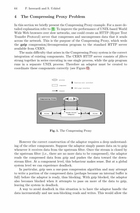
64 P. Inverardi and S. Uchitel
4 The Compressing Proxy Problem
In this section we briefly present the Compressing Proxy example. For a more de-tailed explanation refer to [9]. To improve the performance of UNIX-based WorldWide Web browsers over slow networks, one could create an HTTP (Hyper TextTransfer Protocol) server that compresses and uncompresses data that it sendsacross the network. This is the purpose of the Compressing Proxy, which wedsthe gzip compression/decompression program to the standard HTTP serveravailable from CERN.
The main difficulty that arises in the Compressing Proxy system is the correctintegration of existing components. The CERN HTTP server consists of filtersstrung together in series executing in one single process, while the gzip programruns in a separate UNIX process. Therefore an adaptor must be created tocoordinate these components correctly (see Figure 1).
FilterFilterPseudo Filter
(Adaptor)
gzipCompressing Proxy
process
component
channel
function−call interface
UNIX pipe interface
2 3
1 4
Fig. 1. The Compressing Proxy
However the correct construction of the adaptor requires a deep understand-ing of the other components. Suppose the adaptor simply passes data on to gzipwhenever it receives data from the upstream filter. Once the stream is closed bythe upstream filter (i.e., there are no more data to be compressed), the adaptorreads the compressed data from gzip and pushes the data toward the down-stream filter. At a component level, this behaviour makes sense. But at a globalsystem level we can experience deadlock.
In particular, gzip uses a one-pass compression algorithm and may attemptto write a portion of the compressed data (perhaps because an internal buffer isfull) before the adaptor is ready, thus blocking. With gzip blocked, the adaptoralso becomes blocked when it attempts to pass on more of the data to gzip,leaving the system in deadlock.
A way to avoid deadlock in this situation is to have the adaptor handle thedata incrementally and use non-blocking reads and writes. This would allow the
Proving Deadlock Freedom in Component-Based Programming 65
adaptor to read some data from gzip when its attempt to write data to gzip isblocked.
We model all four system component behaviours, gzip, Adaptor, Upstreamand Downstream CERN filters as the CCS processes in Table 4. The UpstreamCERN filter is very simple, it can continuously perform output actions throughits upstream interface point (u). Similarly, the Downstream Filter can performinput actions through its downstream port (d). The gzip interface consists of aport for inputting the source file (s), one for outputting the compressed file (z ),and two other ports to model end of source file (es) and end of compressed file(ez ). Finally the adaptor interacts with all the other components, and thereforeits interface is the union of all the other component interfaces. The completesystem configuration is given by (UF | GZ | AD | DN) \{u, s, es, z , ez , d} andthe following CCS processes:
Upstream Filter (UF)
UFdef= u.UF
Downstream Filter (DF)
DFdef= d .DF
GZip (GZ)
GZdef= s.In
Indef= s.In + es.z .Out + τ .z .Out
Outdef= z .Out + ez .GZ + τ .GZ
Adaptor (AD)
ADdef= u.s.ToGZ
ToGZdef= s.ToGZ + es.z .FromGZ
FromGZdef= z .FromGZ + ez .d .AD
5 Property Checking Using Assumptions
We represent component behaviour (and component assumptions later on) withdirected, rooted graphs that simply extend labelled transition systems to allowmultiple root nodes:
Definition 2 (Graphs). A (directed rooted) graph G is a tuple of the form(NG ,LG ,AG ,RG) where NG is a set of nodes, LG is a set of labels with τ ∈ LG ,AG ⊆ NG × LG × NG is a set of arcs and RG ⊆ NG is a nonempty set of rootnodes.
– We shall write g l→ h, if there is an arc (g , l , h) ∈ AG . We shall also writeg → h, meaning that g l→ h for some l ∈ LG .
– If t = l1 · · · ln ∈ LG∗, then we write g
t−→∗ h, if g l1→ · · · ln→ h. We shall also
write g −→∗ h, meaning that gt
−→∗ h for some t ∈ LG∗.
– We shall write g l⇒ h, if gt
−→∗ h for some t ∈ τ∗.l .τ∗.
We define the notion of Actual Behaviour (AC) Graph for modelling compo-nent behaviour. The term actual emphasizes the difference between componentbehaviour and the intended, or assumed, behaviour of the environment. AC
66 P. Inverardi and S. Uchitel
graphs model components in an intuitive way. Each node represents a state ofthe component and the root node represents its initial state. Each arc representsthe possible transition into a new state where the transition label is the actionperformed by the component.
Definition 3 (AC Graphs). Let < S ,L,→, s > be a labelled transition sys-tem for component C . We call a graph of the form (S ,L,→, {s}) the ACtualbehaviour graph (AC graph) of a component C . We shall usually denote nodesin AC with ν.
In the rest of the section we will show how component assumptions can bederived and used for proving deadlock freedom in a system composed of a finitenumber of components that communicate synchronously. Following a commonhypothesis in automated checking of properties of complex systems [6], behaviourof all components can be finitely represented. In addition, in order to simplifypresentation, we add two constraints:
– Components can perform each computation infinitely often. In other words,all nodes of a components AC graph are reachable from any other node.This condition simplifies the presentation of the partial equivalence relation.It can easily be dropped by introducing a proper treatment of ending nodesin the definitions below.
– There are no “shared” actions. This means that every communication is onlyused by two components. Again, this condition simplifies the presentationof the checking algorithm and can be easily dropped at the expense of morechecks.
It is worth noticing that dropping the first condition has no implicationon the complexity results of this presentation, while for the second only timecomplexity changes. In Section 6 we discuss more deeply the implications ofboth constraints.
5.1 Deriving Assumptions for Deadlock Freedom
We wish to derive from the behaviour of a component the requirements on itsenvironment that guarantee deadlock freedom. A system is in deadlock when itcannot perform any computation, thus in our setting, deadlock means that allcomponents are blocked waiting for an action from the environment that is notpossible. Our approach is to verify that no components under any circumstancewill block. This conservative approach suffices to prove deadlock freedom exclu-sively from component assumptions. The payback, as we shall show, is efficiency,while the drawback is incompleteness.
As components are combined together composing them in parallel and re-stricting all actions, a component will not block if its environment can alwaysprovide the actions it requires for changing state. Thus we can define the notionof component assumption in the context of parallel composition and deadlockfreedom in the following way:
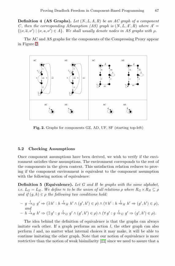
Proving Deadlock Freedom in Component-Based Programming 67
Definition 4 (AS Graphs). Let (N ,L,A,R) be an AC graph of a componentC , then the corresponding ASsumption (AS) graph is (N ,L,A′,R) where A′ ={(ν, a, ν′) | (ν, a, ν′) ∈ A}. We shall usually denote nodes in AS graphs with µ.
The AC and AS graphs for the components of the Compressing Proxy appearin Figure 2.
z
ez
z
AC AS
es
s
t
s
es
s
t ez
z
s
t t
z
s
d
s
AC
u ez
z
z
es
AS
u ez
z
z
d
s
s es
u
AC AS
u d
ASAC
d
Fig. 2. Graphs for components GZ, AD, UF, SF (starting top-left)
5.2 Checking Assumptions
Once component assumptions have been derived, we wish to verify if the envi-ronment satisfies these assumptions. The environment corresponds to the rest ofthe components in the given context. This satisfaction relation reduces to prov-ing if the component environment is equivalent to the component assumptionwith the following notion of equivalence:
Definition 5 (Equivalence). Let G and H be graphs with the same alphabet,i.e. LG = LH . We define ≈ to be the union of all relations ρ where RG ×RH ⊆ ρand if (g , h) ∈ ρ the following two conditions hold:
– g l→G g ′ ⇒ (∃ h ′ : h l⇒H h ′ ∧ (g ′, h ′) ∈ ρ) ∧ (∀ h ′ : h l⇒H h ′ ⇒ (g ′, h ′) ∈ ρ),and
– h l→H h ′ ⇒ (∃ g ′ : g l⇒G g ′ ∧ (g ′, h ′) ∈ ρ) ∧ (∀ g ′ : g l⇒G g ′ ⇒ (g ′, h ′) ∈ ρ).
The idea behind the definition of equivalence is that the graphs can alwaysimitate each other. If a graph performs an action l , the other graph can alsoperform l and, no matter what internal choices it may make, it will be able tocontinue imitating the other graph. Note that our notion of equivalence is morerestrictive than the notion of weak bisimilarity [11] since we need to assure that a
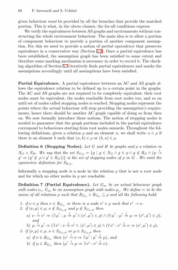
68 P. Inverardi and S. Uchitel
given behaviour must be provided by all the branches that provide the matchedportion. This is what, in the above clauses, the for-all conditions express.
We verify the equivalences between AS graphs and environments without con-structing the whole environment behaviour. The main idea is to allow a portionof component behaviour to provide a portion of another component assump-tion. For this we need to provide a notion of partial equivalence that preservesequivalence in a conservative way (Section 5.2). Once a partial equivalence hasbeen established, the assumption graph has been satisfied to some extent andtherefore some marking mechanism is necessary in order to record it. The check-ing algorithm of Section 5.2 iteratively finds partial equivalences and marks theassumptions accordingly until all assumptions have been satisfied.
Partial Equivalence. A partial equivalence between an AC and AS graph al-lows the equivalence relation to be defined up to a certain point in the graphs.The AC and AS graphs are not required to be completely equivalent, their rootnodes must be equivalent, the nodes reachable from root nodes too, and so onuntil set of nodes called stopping nodes is reached. Stopping nodes represent thepoints where the actual behaviour will stop providing the assumption’s require-ments, hence there should be another AC graph capable of doing so from thenon. We now formally introduce these notions. The notion of stopping nodes isneeded to guarantee that the graph portions included in the partial equivalencecorrespond to behaviours starting from root nodes onwards. Throughout the fol-lowing definitions, given a relation ρ and an element a, we shall write a ∈ ρ ifthere is an element b such that (a, b) ∈ ρ or (b, a) ∈ ρ.
Definition 6 (Stopping Nodes). Let G and H be graphs and ρ a relation inNG × NH . We say that the set SG,ρ = {g | g ∈ NG ∧ g ∈ ρ ∧ g 6∈ RG ∧ (g l→g ′ ⇒ (g ′ 6∈ ρ ∨ g ′ ∈ RG))} is the set of stopping nodes of ρ in G . We omit thesymmetric definition for SH ,ρ.
Informally a stopping node is a node in the relation ρ that is not a root nodeand for which no other nodes in ρ are reachable.
Definition 7 (Partial Equivalence). Let Gac be an actual behaviour graphwith nodes νi , Gas be an assumption graph with nodes µj . We define ' to be theunion of all relations ρ such that RGac × RGas ⊆ ρ and all the following hold:
1. if ν ∈ ρ then ν ∈ RGac or there is a node ν′ ∈ ρ such that ν′ → ν.2. if (ν, µ) ∈ ρ, ν 6∈ SGac ,ρ and µ 6∈ SGas ,ρ then
a) νl→ ν′ ⇒ (∃µ
′ : µl⇒ µ
′ ∧ (ν′, µ′) ∈ ρ) ∧ (∀µ′ : µ
′ l⇒ µ ⇒ (ν′, µ′) ∈ ρ),and
b) µl→ µ
′ ⇒ (∃ ν′ : νl⇒ ν′ ∧ (ν′, µ′) ∈ ρ) ∧ (∀ ν′ : ν′ l⇒ ν ⇒ (ν′, µ′) ∈ ρ).
3. if (ν, µ) ∈ ρ, ν ∈ SGac ,ρ or µ ∈ SGas ,ρ thena) if ν ∈ RGac then (ν′ l→ ν ⇒ ∃µ
′ : µ′ l⇒ µ), and
b) if µ ∈ RGas then (µ′ l→ µ ⇒ ∃ ν′ : ν′ l⇒ ν).
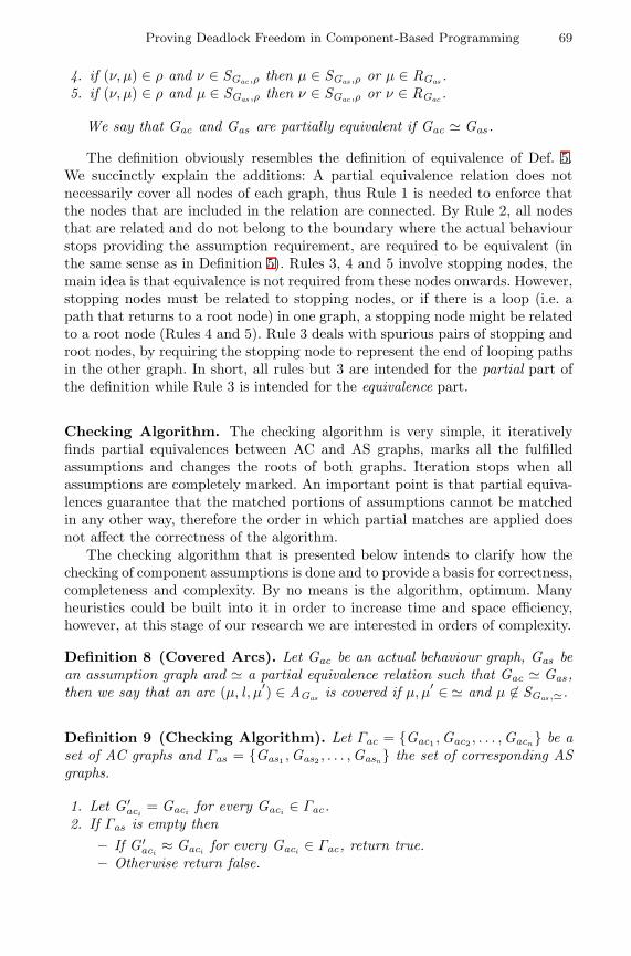
Proving Deadlock Freedom in Component-Based Programming 69
4. if (ν, µ) ∈ ρ and ν ∈ SGac ,ρ then µ ∈ SGas ,ρ or µ ∈ RGas .5. if (ν, µ) ∈ ρ and µ ∈ SGas ,ρ then ν ∈ SGac ,ρ or ν ∈ RGac .
We say that Gac and Gas are partially equivalent if Gac ' Gas .
The definition obviously resembles the definition of equivalence of Def. 5.We succinctly explain the additions: A partial equivalence relation does notnecessarily cover all nodes of each graph, thus Rule 1 is needed to enforce thatthe nodes that are included in the relation are connected. By Rule 2, all nodesthat are related and do not belong to the boundary where the actual behaviourstops providing the assumption requirement, are required to be equivalent (inthe same sense as in Definition 5). Rules 3, 4 and 5 involve stopping nodes, themain idea is that equivalence is not required from these nodes onwards. However,stopping nodes must be related to stopping nodes, or if there is a loop (i.e. apath that returns to a root node) in one graph, a stopping node might be relatedto a root node (Rules 4 and 5). Rule 3 deals with spurious pairs of stopping androot nodes, by requiring the stopping node to represent the end of looping pathsin the other graph. In short, all rules but 3 are intended for the partial part ofthe definition while Rule 3 is intended for the equivalence part.
Checking Algorithm. The checking algorithm is very simple, it iterativelyfinds partial equivalences between AC and AS graphs, marks all the fulfilledassumptions and changes the roots of both graphs. Iteration stops when allassumptions are completely marked. An important point is that partial equiva-lences guarantee that the matched portions of assumptions cannot be matchedin any other way, therefore the order in which partial matches are applied doesnot affect the correctness of the algorithm.
The checking algorithm that is presented below intends to clarify how thechecking of component assumptions is done and to provide a basis for correctness,completeness and complexity. By no means is the algorithm, optimum. Manyheuristics could be built into it in order to increase time and space efficiency,however, at this stage of our research we are interested in orders of complexity.
Definition 8 (Covered Arcs). Let Gac be an actual behaviour graph, Gas bean assumption graph and ' a partial equivalence relation such that Gac ' Gas ,then we say that an arc (µ, l , µ′) ∈ AGas is covered if µ, µ
′ ∈ ' and µ 6∈ SGas ,'.
Definition 9 (Checking Algorithm). Let Γac = {Gac1 ,Gac2 , . . . ,Gacn } be aset of AC graphs and Γas = {Gas1 ,Gas2 , . . . ,Gasn } the set of corresponding ASgraphs.
1. Let G ′aci
= Gaci for every Gaci ∈ Γac.2. If Γas is empty then
– If G ′aci
≈ Gaci for every Gaci ∈ Γac, return true.– Otherwise return false.
70 P. Inverardi and S. Uchitel
3. Try to find an AC graph Gaci in Γac, an AS graph Gasj in Γas , and a partialequivalence between them (Gaci ' Gasj ). If it is not found, return false.
4. Relabel with τ every arc in Gasj that is covered by '. If all arcs in Gasj arelabeled τ remove it from Γas .
5. If Sas ∪ Sac 6= ∅ then let RGasi= {µ | µ ∈ Sas ∨ ∃ ν ∈ Sac : ν ' µ} and let
RGaci= {ν | ν ∈ Sac ∨ ∃µ ∈ Sas : ν ' µ}.
6. Go to step 2.
Note that the algorithm returns true only if all assumptions have been sat-isfied and the system configuration is in a setting equivalent to its initial state(Step 4).
We now apply the algorithm to the Compressing Proxy example. We rep-resent partial equivalences with dotted lines for related nodes and crosses forstopping nodes. In figure 3, the Upstream Filter matches successfully with theAdaptor. Once the successful match has been made, both graphs are modified.The new state of the Adaptor can be seen in figure 4.
AC
u
AS
u ez
z
z
d
s
ses
Fig. 3. Successful match of Upstream Filter AC and Adaptor AS graphs
Figure 4 shows how a partial match can be established between the gzip ACgraph and the Adaptor AS graph. However it is possible to see that there isno way of extending the relation in order to cover the edge labelled es. Hencethe algorithm, after all possible attempts, terminates at Step 2 returning false;meaning that the proposed configuration is presumably not deadlock free.
z
ez
z
AS
ez
z
z
d
s
ses
t
AC
es
s
t
s
t
Fig. 4. Unsuccessful match of gzip AC and Adaptor AS graphs
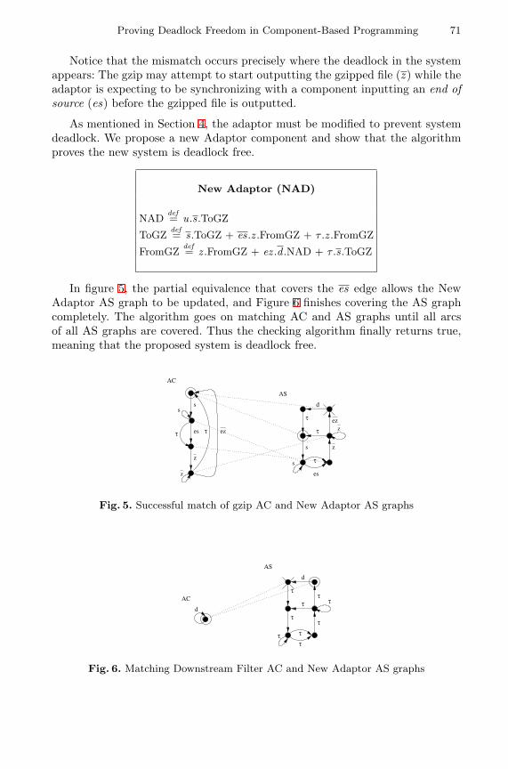
Proving Deadlock Freedom in Component-Based Programming 71
Notice that the mismatch occurs precisely where the deadlock in the systemappears: The gzip may attempt to start outputting the gzipped file (z ) while theadaptor is expecting to be synchronizing with a component inputting an end ofsource (es) before the gzipped file is outputted.
As mentioned in Section 4, the adaptor must be modified to prevent systemdeadlock. We propose a new Adaptor component and show that the algorithmproves the new system is deadlock free.
New Adaptor (NAD)
NADdef= u.s.ToGZ
ToGZdef= s.ToGZ + es.z .FromGZ + τ .z .FromGZ
FromGZdef= z .FromGZ + ez .d .NAD + τ .s.ToGZ
In figure 5, the partial equivalence that covers the es edge allows the NewAdaptor AS graph to be updated, and Figure 6 finishes covering the AS graphcompletely. The algorithm goes on matching AC and AS graphs until all arcsof all AS graphs are covered. Thus the checking algorithm finally returns true,meaning that the proposed system is deadlock free.
ez
z
zt
es
t
AS
d
s
s
t
z
ez
z
AC
es
s
t
s
t
Fig. 5. Successful match of gzip AC and New Adaptor AS graphs
d
ACt
t
AS
d
tt
t
tt
tt
Fig. 6. Matching Downstream Filter AC and New Adaptor AS graphs
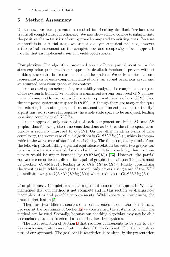
72 P. Inverardi and S. Uchitel
6 Method Assessment
Up to now, we have presented a method for checking deadlock freedom thattrades off completeness for efficiency. We now show some evidence to substantiatethe positive characteristics of our approach compared to existing ones. Becauseour work is in an initial stage, we cannot give, yet, empirical evidence, howevera theoretical assessment on the completeness and complexity of our approachreveals that an implementation will yield good results.
Complexity. The algorithm presented above offers a partial solution to thestate explosion problem. In our approach, deadlock freedom is proven withoutbuilding the entire finite-state model of the system. We only construct finiterepresentations of each component individually: an actual behaviour graph andan assumed behaviour graph of its context.
In standard approaches, using reachability analysis, the complete state spaceof the system is built. If we consider a concurrent system composed of N compo-nents of comparable size, whose finite state representation is of size O(K ), thenthe composed system state space is O(KN ). Although there are many techniquesfor reducing the state space, such as automata minimization and “on the fly”algorithms, worst case still requires the whole state space to be analysed, leadingto a time complexity of O(KN ).
In our approach only two copies of each component are built, AC and ASgraphs, thus following the same considerations as before, the state space com-plexity is radically improved to O(KN ). On the other hand, in terms of timecomplexity, the worst case of our algorithm is O(N 3K 4log(K )), which is compa-rable to the worst case of standard reachability. The time complexity results fromthe following: Establishing a partial equivalence relation between two graphs canbe considered a variation of the standard bisimulation checking, thus its com-plexity would be upper bounded by O(K 2log(K )) [13]. However, the partialequivalence must be established for a pair of graphs, thus all possible pairs mustbe checked (Comb(N , 2)), leading us to O(N 2(K 2log(K ))). Finally, consideringthe worst case in which each partial match only covers a single arc of the NK 2
possibilities, we get O(K 2N 3(K 2log(K ))) which reduces to O(N 3K 4log(K )).
Completeness. Completeness is an important issue in our approach. We havementioned that our method is not complete and in this section we discuss howincomplete it is and possible improvements. With respect to correctness, theproof is sketched in [8].
There are two different sources of incompleteness in our approach. Firstly,because at the beginning of Section 5 we constrained the systems for which themethod can be used. Secondly, because our checking algorithm may not be ableto conclude deadlock freedom for some deadlock free systems.
The first restriction of Section 5 that requires components to be able to per-form each computation an infinite number of times does not affect the complete-ness of our approach. The goal of this restriction is to simplify the presentation
Proving Deadlock Freedom in Component-Based Programming 73
of definitions. Dropping the constraint requires defining the concept of recursivearcs as arcs that can be taken infinite times and modifying the matching scheme:recursive arcs of AS graphs can only be matched with recursive AC graphs whilenon-recursive arcs must match with non-recursive arcs. Definitions of this kindcan be found in [9].
The restriction on shared channels is more serious. If a channel can be usedby more than two components, there is potential global non-determinism in theoverall system behaviour. A component may have the possibility of synchronizingwith one of several components leading to a non-deterministic choice on thepartner to which synchronize with. In terms of our approach, this means thatone cannot commit to which AC graph will provide the AS graph requirements.Because the matching process guarantees that the matched arcs of the AS graphwill always be provided by the AC graph, no matching can be done. This non-determinism introduced by shared channels is similar to the non-determinismthat makes our algorithm incomplete; therefore we will discuss a solution toboth problems farther on in the section.
Having discussed the restriction imposed on components, the incompletenessof the checking algorithm remains. Our approach is intrinsically incomplete. Weattempt to prove a global property such as deadlock freedom in terms of localproperties of each component. That is we say that the system is deadlock freeif no system component can ever block. Obviously this is a strong sufficientcondition but by no mean a necessary one.
As a consequence, the characteristics of our setting lead to the following situ-ation: Given a deadlock free system, the algorithm may not be able to concludethat it is deadlock free. The algorithm reaches a state in which it cannot dofurther matches between AC and AS graphs. One reason for this is that thedefinition of partial match may be just too restrictive, leaving out some matchesthat might be correct. Compared to the previous version of this approach [9]the notion of partial match represents an improvement since it does not requirematching between AC and AS graphs to use the entire AC graph to prove dead-lock freedom. Examples that can be verified with the partial matching introducedin this paper and not with the previous versions of the approach can be foundin [8].
However, the main reason for the incompleteness of our approach is connectedto non-determinism. When there is a non-deterministic choice in component be-haviour, when a component can interact with one of two different components,there can be not a unique matching that guarantees how the system will evolve.In these situations the algorithm stops without obtaining AS graphs completelymatched, and therefore not giving a conclusive answer (Note that this is stillless restrictive than the approach in [2]). In order to solve this problem we areworking in the direction of changing the main algorithm in the following way:When there is a choice in the AS graph and it is not possible to match allchoices simultaneously, the choices must be selected in turns. For each selection,the algorithm proceeds matching. If the checking algorithm succeeds matchingall AS graphs, it tries the rest of the choices. If checking succeeds for all choices,
74 P. Inverardi and S. Uchitel
then it succeeds for the complete AS graph. This improvement on complete-ness does not have a drastic impact on complexity. In terms of time complexity,there is an important increase; however, in terms of space complexity, the mod-ification presents no significant changes. No new graphs must be represented,the algorithm has to register the non-deterministic points and go back to them.Thus, space complexity will not jump to an exponential order, maintaining theadvantages the approach has with respect to other methods.
Summarizing, the approach we present is incomplete but we think there isroom for significant improvements. On the other hand, incompleteness is theprice that must be paid to make analysis tractable. Our method may apply onlyto a subset of problems but it lowers complexity of the solution from exponentialorder to a polynomial one.
7 Conclusions and Future Work
In this work we have presented a broader notion of component semantics based onassumptions and a derived space-efficient method for proving deadlock freedomin a component based setting. This method is based on deriving assumptions(component requirements on its environment in order to guarantee a certainproperty in a specific composition context) and checking that all assumptionsare guaranteed through a partial matching mechanism. The method is consid-erably more efficient than methods based on system model behaviour analysis,its space complexity is polynomial while existing approaches have exponentialorders of magnitude. It is not complete but it allows the treatment of systemswhose synchronization patterns are not trivial. We think it can be a useful tool tobe included in a verification tool-set together with complete but not always ap-plicable ones. Our approach heavily relies on the component-based setting. Thisis a very interesting context in which experimenting new verification techniques.In fact, on one side components by definition force standardization and thereforesimplifications of the integration frameworks. On the other side there is roomfor suggestions on the kind of information that a component should explicitlycarry on with it in order to be integrated in all suitable contexts. That is thenotion of component semantics is conceived in broader terms than in traditionalprogramming.
Dynamic properties are difficult to be proven and, as we discussed in Section2, most of the proposed approaches to overcome state explosion are based oncharacterizing local properties and then try to ensure that these properties can belifted up to the global system level. Our contribution is actually in this line, butwith the aim of fixing once and for all the kind of information that a componenthas to carry with it independently of the contexts it will eventually be used. Tothis respect, we believe that assumptions are a good way to extend componentsemantics in order to verify properties more efficiently.
Ongoing and future work goes in several directions. Firstly, we are working onthe validation of the framework through experimental results. We are currentlyworking on an implementation of the algorithm, and considering other coordi-
Proving Deadlock Freedom in Component-Based Programming 75
nation contexts like non-fully synchronized or asynchronous ones. In particularwe are trying to cast our approach in given architectural styles and experimentwith commercial component base frameworks as COM. Second, we wish to ex-tend the approach to deal with other properties such as general liveness andsafety properties. To this respect we are thinking of general safety propertiesexpressed with property automata that may be decomposed into component as-sumptions or specific component assumptions such as particular access protocolsfor shared resources. Lastly, we are working on an extension of the algorithm inorder to improve completeness of our approach.
Acknowledgements. We would like to thank Alexander Wolf and DanielYankelevich for discussions and previous work on the subject of the paper.
References
1. R. Alur, L. de Alfaro, T. A. Henzinger, and F. Y. C. Mang. Automatic modularverification. In Proceedings of CONCUR ’99: Concurrency Theory, 1999.
2. F. Arbab, F.S. de Boer, and M. M. Bonsangue. A logical interface descriptionlanguage for components. In COORDINATION’00, vol. 1906 of LNCS. Springer,2000.
3. J. R. Burch, E. M. Clarke, K. L. McMillan, D. L. Dill, and L.J. Hwang. Symbolicmodel checking : 1020 and beyond. Information and Computation, 98:142–170,June 1992.
4. R. Cleaveland, J. Parrow, and B. Steffen. The concurrency workbench: a seman-tics based tool for the verification of concurrent systems. ACM Transactions onProgramming Languages and Systems, 15(1):36–72, January 1993.
5. D. Garlan, R. Allen, and J. Ockerbloom. Architectural mismatch: Why reuse is sohard. IEEE Software, 12(6), November 1995.
6. D. Giannakopoulou, J. Kramer, and S.C. Cheung. Analysing the behaviour ofdistributed systems using tracta. Automated Software Engineering, 6(1):7–35, 1999.
7. S. Graf, B. Steffen, and G. Luttgen. Compositional minimisation of finite statesystems using interface specifications. Formal Aspects of Computing, 8(5), 1998.
8. P. Inverardi and S. Uchitel. Proving deadlock freedom in component-basedprogramming. Technical report, Universita’ dell’Aquila, Italia, October 1999.http://www.doc.ic.ac.uk/ su2/pubs/techrep99.pdf
9. P. Inverardi, D. Yankelevich, and A. Wolf. Static checking of systems behaviorsusing derived component assumptions. ACM TOSEM, 2000.
10. N. Kobayashi. A partially deadlock-free typed process calculus. ACM Transactionson Programming Languages and Systems, 20(2):436–482, March 1998.
11. R. Milner. Communication and Concurrency. Prentice Hall, New York, 1989.12. O.Grumberg and D.E.Long. Model checking and modular verification. ACM Trans-
actions on Programming Languages and Systems, 16(3):843–871, May 1994.13. R. Paige and R.E. Tarjan. Three partition refinement algorithms. SIAM Journal
on Computing, 16(6):973–989, 1987.14. Clemens Szyperski. Component Software. Beyond Object Oriented Programming.
Addison Wesley, Harlow, England, 1998.
A Real-Time Execution Semanticsfor UML Activity Diagrams
Rik Eshuis? and Roel Wieringa
University of Twente, Department of Computer ScienceP.O. Box 217, 7500 AE Enschede, The Netherlands
{eshuis,roelw}@cs.utwente.nl
Abstract. We define a formal execution semantics for UML activitydiagrams that is appropriate for workflow modelling. Our semantics isaimed at the requirements level by assuming that software state changesdo not take time. It is based upon the Statemate semantics of stat-echarts, extended with some transactional properties to deal with datamanipulation. Our semantics also deals with real-time and multiple stateinstances. We first give an informal description of our semantics and thenformalise this in terms of transition systems.
1 Introduction
A workflow is a set of business activities that are ordered according to a set ofprocedural rules to deliver a service. A workflow model (or workflow specifica-tion) is the definition of a workflow. An instance of a workflow is called a case.Examples of cases are an insurance claim handling instance and a productionorder handling instance. The definition, creation, and management of workflowinstances is done by a workflow management system (WFMS), on the basis ofworkflow models. We represent workflow models by UML activity diagrams [16].
In this paper, we define a formal execution semantics for UML activity di-agrams that is suitable for workflow modelling. The goal of the semantics isto support execution of workflow models and analysis of the functional require-ments that these models satisfy. Our long term goal is to implement the executionsemantics in the TCM case tool [6] and to use model checking tools for the anal-ysis of functional requirements. A secondary goal of the semantics is to facilitatea comparison with other formal modelling techniques for workflows, like Petrinets [1] and statecharts [18]. For example, some people claim that an activitydiagram is a Petri net. But in order to sustain this claim, first a formal semanticsfor activity diagrams must be defined, so that the Petri net semantics and theactivity diagram semantics can be compared.
Figure 1 shows an example activity diagram. Ovals represent activity states,rounded rectangles represent wait states, and arrows represent state transitions.Section 3 explains the details of the notation. We use activity diagrams to modela single instance (case) of a workflow. We defer the modelling of multiple cases(case management) to future work.? Supported by NWO/SION, grant nr. 612-62-02 (DAEMON).
H. Hussmann (Ed.): FASE 2001, LNCS 2029, pp. 76–90, 2001.c© Springer-Verlag Berlin Heidelberg 2001
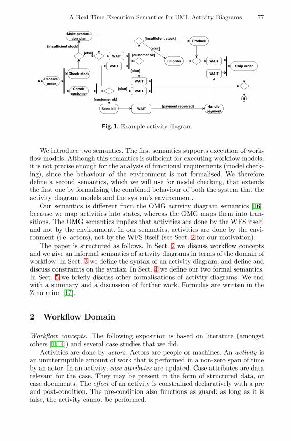
A Real-Time Execution Semantics for UML Activity Diagrams 77
Receive order
Check stock
Send bill
Ship order
Check customer
[customer ok]
[else]
Make produc−tion plan
Produce
[else]
[insufficient stock]
[else]
WAITHandle payment
[payment received]
Fill order
[customer ok]
[insufficient stock]
[else]
WAIT
WAITWAIT
WAIT
WAIT
WAIT
Fig. 1. Example activity diagram
We introduce two semantics. The first semantics supports execution of work-flow models. Although this semantics is sufficient for executing workflow models,it is not precise enough for the analysis of functional requirements (model check-ing), since the behaviour of the environment is not formalised. We thereforedefine a second semantics, which we will use for model checking, that extendsthe first one by formalising the combined behaviour of both the system that theactivity diagram models and the system’s environment.
Our semantics is different from the OMG activity diagram semantics [16],because we map activities into states, whereas the OMG maps them into tran-sitions. The OMG semantics implies that activities are done by the WFS itself,and not by the environment. In our semantics, activities are done by the envi-ronment (i.e. actors), not by the WFS itself (see Sect. 2 for our motivation).
The paper is structured as follows. In Sect. 2 we discuss workflow conceptsand we give an informal semantics of activity diagrams in terms of the domain ofworkflow. In Sect. 3 we define the syntax of an activity diagram, and define anddiscuss constraints on the syntax. In Sect. 4 we define our two formal semantics.In Sect. 5 we briefly discuss other formalisations of activity diagrams. We endwith a summary and a discussion of further work. Formulas are written in theZ notation [17].
2 Workflow Domain
Workflow concepts. The following exposition is based on literature (amongstothers [1,14]) and several case studies that we did.
Activities are done by actors. Actors are people or machines. An activity isan uninterruptible amount of work that is performed in a non-zero span of timeby an actor. In an activity, case attributes are updated. Case attributes are datarelevant for the case. They may be present in the form of structured data, orcase documents. The effect of an activity is constrained declaratively with a preand post-condition. The pre-condition also functions as guard: as long as it isfalse, the activity cannot be performed.
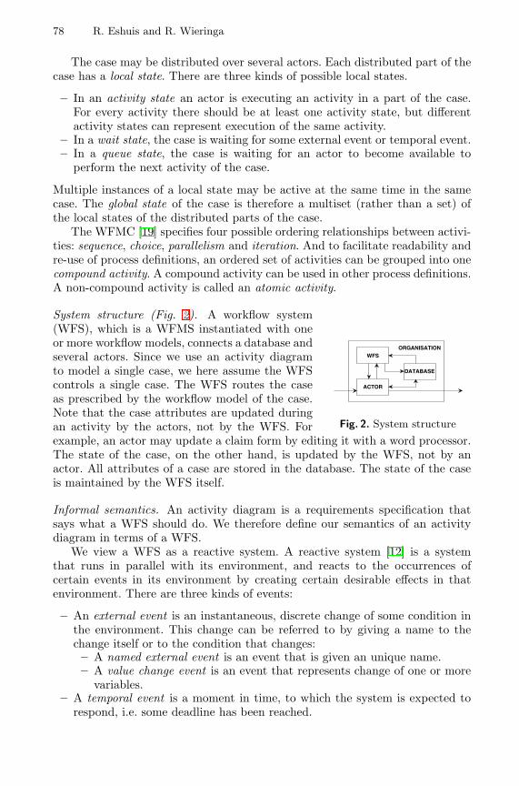
78 R. Eshuis and R. Wieringa
The case may be distributed over several actors. Each distributed part of thecase has a local state. There are three kinds of possible local states.
– In an activity state an actor is executing an activity in a part of the case.For every activity there should be at least one activity state, but differentactivity states can represent execution of the same activity.
– In a wait state, the case is waiting for some external event or temporal event.– In a queue state, the case is waiting for an actor to become available to
perform the next activity of the case.
Multiple instances of a local state may be active at the same time in the samecase. The global state of the case is therefore a multiset (rather than a set) ofthe local states of the distributed parts of the case.
The WFMC [19] specifies four possible ordering relationships between activi-ties: sequence, choice, parallelism and iteration. And to facilitate readability andre-use of process definitions, an ordered set of activities can be grouped into onecompound activity. A compound activity can be used in other process definitions.A non-compound activity is called an atomic activity.
WFS
DATABASE
ACTOR
ORGANISATION
Fig. 2. System structure
System structure (Fig. 2). A workflow system(WFS), which is a WFMS instantiated with oneor more workflow models, connects a database andseveral actors. Since we use an activity diagramto model a single case, we here assume the WFScontrols a single case. The WFS routes the caseas prescribed by the workflow model of the case.Note that the case attributes are updated duringan activity by the actors, not by the WFS. Forexample, an actor may update a claim form by editing it with a word processor.The state of the case, on the other hand, is updated by the WFS, not by anactor. All attributes of a case are stored in the database. The state of the caseis maintained by the WFS itself.
Informal semantics. An activity diagram is a requirements specification thatsays what a WFS should do. We therefore define our semantics of an activitydiagram in terms of a WFS.
We view a WFS as a reactive system. A reactive system [12] is a systemthat runs in parallel with its environment, and reacts to the occurrences ofcertain events in its environment by creating certain desirable effects in thatenvironment. There are three kinds of events:
– An external event is an instantaneous, discrete change of some condition inthe environment. This change can be referred to by giving a name to thechange itself or to the condition that changes:– A named external event is an event that is given an unique name.– A value change event is an event that represents change of one or more
variables.– A temporal event is a moment in time, to which the system is expected to
respond, i.e. some deadline has been reached.
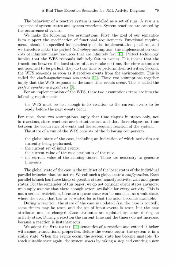
A Real-Time Execution Semantics for UML Activity Diagrams 79
The behaviour of a reactive system is modelled as a set of runs. A run is asequence of system states and system reactions. System reactions are caused bythe occurrence of events.
We make the following two assumptions. First, the goal of our semanticsis to support the specification of functional requirements. Functional require-ments should be specified independently of the implementation platform, andwe therefore make the perfect technology assumption: the implementation con-sists of infinitely many resources that are infinitely fast [15]. Perfect technologyimplies that the WFS responds infinitely fast to events. This means that thetransitions between the local states of a case take no time. But since actors arenot assumed to be perfect, they do take time to perform their activities. Second,the WFS responds as soon as it receives events from the environment. This iscalled the clock-asynchronous semantics [11]. These two assumptions togetherimply that the WFS responds at the same time events occur. This is called theperfect synchrony hypothesis [3].
For an implementation of the WFS, these two assumptions translate into thefollowing requirement:
the WFS must be fast enough in its reaction to the current events to beready before the next events occur
For runs, these two assumptions imply that time elapses in states only, notin reactions, since reactions are instantaneous, and that there elapses no timebetween the occurrence of events and the subsequent reaction of the system.
The state of a run of the WFS consists of the following components:
– the global state of the case, including an indication of which activities arecurrently being performed,
– the current set of input events,– the current value of the case attributes of the case,– the current value of the running timers. These are necessary to generate
time-outs.
The global state of the case is the multiset of the local states of the individualparallel branches that are active. We call such a global state a configuration. Eachparallel branch has three kinds of possible states, namely activity, wait and queuestates. For the remainder of this paper, we do not consider queue states anymore;we simply assume that there enough actors available for every activity. This isnot a serious restriction, because a queue state can be modelled as a wait state,where the event that has to be waited for is that the actor becomes available.
During a reaction, the state of the case is updated (i.e. the case is routed),some timers may be reset, and the set of input events is reset, but the caseattributes are not changed. Case attributes are updated by actors during anactivity state. During a reaction the current time and the timers do not increase,because a reaction is instantaneous.
We adopt the Statemate [11] semantics of a reaction and extend it belowwith some transactional properties. Before the events occur, the system is in astable state. When the events occur, the system state has become unstable. Toreach a stable state again, the system reacts by taking a step and entering a new
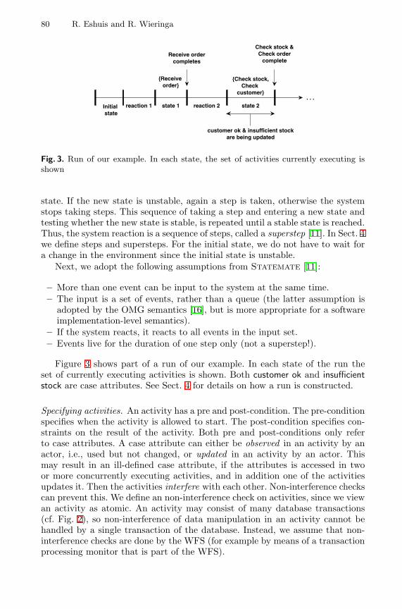
80 R. Eshuis and R. Wieringa
Initial state
reaction 1
{Receive order}
reaction 2
{Check stock,Check
customer}
Receive ordercompletes
Check stock &Check order
complete
customer ok & insufficient stockare being updated
. . .state 1 state 2
Fig. 3. Run of our example. In each state, the set of activities currently executing isshown
state. If the new state is unstable, again a step is taken, otherwise the systemstops taking steps. This sequence of taking a step and entering a new state andtesting whether the new state is stable, is repeated until a stable state is reached.Thus, the system reaction is a sequence of steps, called a superstep [11]. In Sect. 4we define steps and supersteps. For the initial state, we do not have to wait fora change in the environment since the initial state is unstable.
Next, we adopt the following assumptions from Statemate [11]:
– More than one event can be input to the system at the same time.– The input is a set of events, rather than a queue (the latter assumption is
adopted by the OMG semantics [16], but is more appropriate for a softwareimplementation-level semantics).
– If the system reacts, it reacts to all events in the input set.– Events live for the duration of one step only (not a superstep!).
Figure 3 shows part of a run of our example. In each state of the run theset of currently executing activities is shown. Both customer ok and insufficientstock are case attributes. See Sect. 4 for details on how a run is constructed.
Specifying activities. An activity has a pre and post-condition. The pre-conditionspecifies when the activity is allowed to start. The post-condition specifies con-straints on the result of the activity. Both pre and post-conditions only referto case attributes. A case attribute can either be observed in an activity by anactor, i.e., used but not changed, or updated in an activity by an actor. Thismay result in an ill-defined case attribute, if the attributes is accessed in twoor more concurrently executing activities, and in addition one of the activitiesupdates it. Then the activities interfere with each other. Non-interference checkscan prevent this. We define an non-interference check on activities, since we viewan activity as atomic. An activity may consist of many database transactions(cf. Fig. 2), so non-interference of data manipulation in an activity cannot behandled by a single transaction of the database. Instead, we assume that non-interference checks are done by the WFS (for example by means of a transactionprocessing monitor that is part of the WFS).
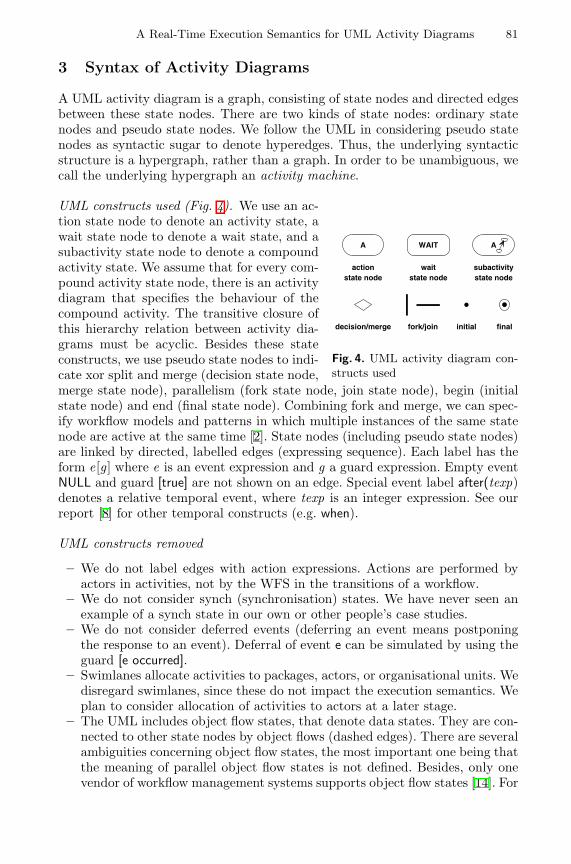
A Real-Time Execution Semantics for UML Activity Diagrams 81
3 Syntax of Activity Diagrams
A UML activity diagram is a graph, consisting of state nodes and directed edgesbetween these state nodes. There are two kinds of state nodes: ordinary statenodes and pseudo state nodes. We follow the UML in considering pseudo statenodes as syntactic sugar to denote hyperedges. Thus, the underlying syntacticstructure is a hypergraph, rather than a graph. In order to be unambiguous, wecall the underlying hypergraph an activity machine.
A
actionstate node
WAIT
waitstate node
decision/merge fork/join
A
initial final
subactivitystate node
Fig. 4. UML activity diagram con-structs used
UML constructs used (Fig. 4). We use an ac-tion state node to denote an activity state, await state node to denote a wait state, and asubactivity state node to denote a compoundactivity state. We assume that for every com-pound activity state node, there is an activitydiagram that specifies the behaviour of thecompound activity. The transitive closure ofthis hierarchy relation between activity dia-grams must be acyclic. Besides these stateconstructs, we use pseudo state nodes to indi-cate xor split and merge (decision state node,merge state node), parallelism (fork state node, join state node), begin (initialstate node) and end (final state node). Combining fork and merge, we can spec-ify workflow models and patterns in which multiple instances of the same statenode are active at the same time [2]. State nodes (including pseudo state nodes)are linked by directed, labelled edges (expressing sequence). Each label has theform e[g ] where e is an event expression and g a guard expression. Empty eventNULL and guard [true] are not shown on an edge. Special event label after(texp)denotes a relative temporal event, where texp is an integer expression. See ourreport [8] for other temporal constructs (e.g. when).
UML constructs removed
– We do not label edges with action expressions. Actions are performed byactors in activities, not by the WFS in the transitions of a workflow.
– We do not consider synch (synchronisation) states. We have never seen anexample of a synch state in our own or other people’s case studies.
– We do not consider deferred events (deferring an event means postponingthe response to an event). Deferral of event e can be simulated by using theguard [e occurred].
– Swimlanes allocate activities to packages, actors, or organisational units. Wedisregard swimlanes, since these do not impact the execution semantics. Weplan to consider allocation of activities to actors at a later stage.
– The UML includes object flow states, that denote data states. They are con-nected to other state nodes by object flows (dashed edges). There are severalambiguities concerning object flow states, the most important one being thatthe meaning of parallel object flow states is not defined. Besides, only onevendor of workflow management systems supports object flow states [14]. For
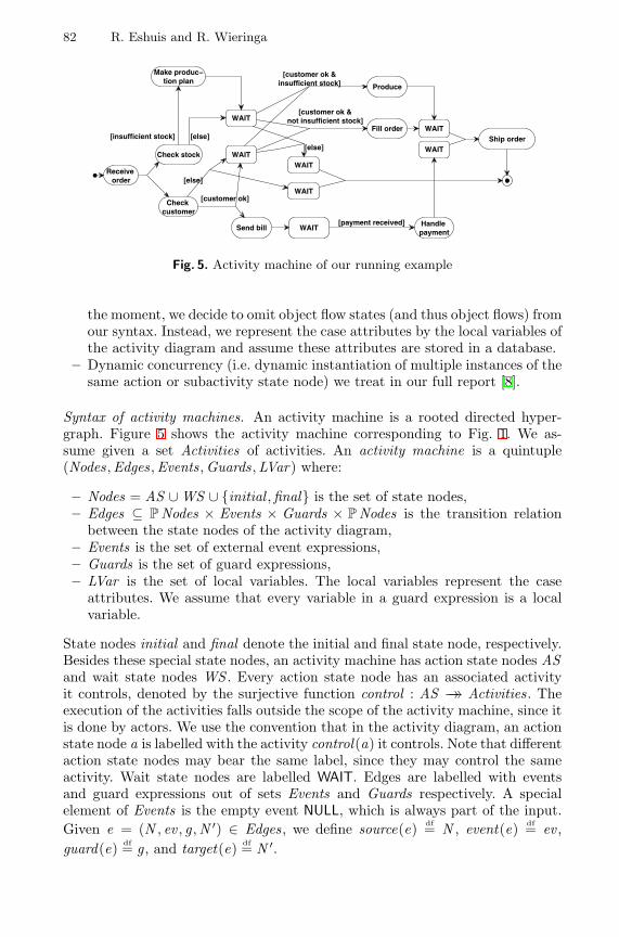
82 R. Eshuis and R. Wieringa
Receive order
Check stock
Send bill
Ship order
Check customer
Make produc−tion plan
Produce
[else][insufficient stock]
WAIT Handle payment
[payment received]
Fill order
WAIT
WAITWAIT
WAIT
WAIT
WAIT
[else]
[customer ok]
[customer ok &insufficient stock]
[else]
[customer ok ¬ insufficient stock]
Fig. 5. Activity machine of our running example
the moment, we decide to omit object flow states (and thus object flows) fromour syntax. Instead, we represent the case attributes by the local variables ofthe activity diagram and assume these attributes are stored in a database.
– Dynamic concurrency (i.e. dynamic instantiation of multiple instances of thesame action or subactivity state node) we treat in our full report [8].
Syntax of activity machines. An activity machine is a rooted directed hyper-graph. Figure 5 shows the activity machine corresponding to Fig. 1. We as-sume given a set Activities of activities. An activity machine is a quintuple(Nodes,Edges,Events,Guards,LVar) where:
– Nodes = AS ∪ WS ∪ {initial ,final} is the set of state nodes,– Edges ⊆ P Nodes × Events × Guards × P Nodes is the transition relation
between the state nodes of the activity diagram,– Events is the set of external event expressions,– Guards is the set of guard expressions,– LVar is the set of local variables. The local variables represent the case
attributes. We assume that every variable in a guard expression is a localvariable.
State nodes initial and final denote the initial and final state node, respectively.Besides these special state nodes, an activity machine has action state nodes ASand wait state nodes WS . Every action state node has an associated activityit controls, denoted by the surjective function control : AS →→ Activities. Theexecution of the activities falls outside the scope of the activity machine, since itis done by actors. We use the convention that in the activity diagram, an actionstate node a is labelled with the activity control(a) it controls. Note that differentaction state nodes may bear the same label, since they may control the sameactivity. Wait state nodes are labelled WAIT. Edges are labelled with eventsand guard expressions out of sets Events and Guards respectively. A specialelement of Events is the empty event NULL, which is always part of the input.Given e = (N , ev , g ,N ′) ∈ Edges, we define source(e) df= N , event(e) df= ev ,guard(e) df= g , and target(e) df= N ′.
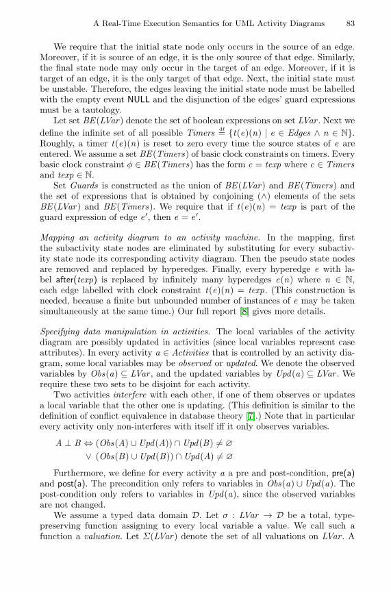
A Real-Time Execution Semantics for UML Activity Diagrams 83
We require that the initial state node only occurs in the source of an edge.Moreover, if it is source of an edge, it is the only source of that edge. Similarly,the final state node may only occur in the target of an edge. Moreover, if it istarget of an edge, it is the only target of that edge. Next, the initial state mustbe unstable. Therefore, the edges leaving the initial state node must be labelledwith the empty event NULL and the disjunction of the edges’ guard expressionsmust be a tautology.
Let set BE (LVar) denote the set of boolean expressions on set LVar . Next wedefine the infinite set of all possible Timers df= {t(e)(n) | e ∈ Edges ∧ n ∈ N}.Roughly, a timer t(e)(n) is reset to zero every time the source states of e areentered. We assume a set BE (Timers) of basic clock constraints on timers. Everybasic clock constraint φ ∈ BE (Timers) has the form c = texp where c ∈ Timersand texp ∈ N.
Set Guards is constructed as the union of BE (LVar) and BE (Timers) andthe set of expressions that is obtained by conjoining (∧) elements of the setsBE (LVar) and BE (Timers). We require that if t(e)(n) = texp is part of theguard expression of edge e ′, then e = e ′.
Mapping an activity diagram to an activity machine. In the mapping, firstthe subactivity state nodes are eliminated by substituting for every subactiv-ity state node its corresponding activity diagram. Then the pseudo state nodesare removed and replaced by hyperedges. Finally, every hyperedge e with la-bel after(texp) is replaced by infinitely many hyperedges e(n) where n ∈ N,each edge labelled with clock constraint t(e)(n) = texp. (This construction isneeded, because a finite but unbounded number of instances of e may be takensimultaneously at the same time.) Our full report [8] gives more details.
Specifying data manipulation in activities. The local variables of the activitydiagram are possibly updated in activities (since local variables represent caseattributes). In every activity a ∈ Activities that is controlled by an activity dia-gram, some local variables may be observed or updated. We denote the observedvariables by Obs(a) ⊆ LVar , and the updated variables by Upd(a) ⊆ LVar . Werequire these two sets to be disjoint for each activity.
Two activities interfere with each other, if one of them observes or updatesa local variable that the other one is updating. (This definition is similar to thedefinition of conflict equivalence in database theory [7].) Note that in particularevery activity only non-interferes with itself iff it only observes variables.
A ⊥ B ⇔ (Obs(A) ∪ Upd(A)) ∩ Upd(B) 6= ∅
∨ (Obs(B) ∪ Upd(B)) ∩ Upd(A) 6= ∅
Furthermore, we define for every activity a a pre and post-condition, pre(a)and post(a). The precondition only refers to variables in Obs(a) ∪ Upd(a). Thepost-condition only refers to variables in Upd(a), since the observed variablesare not changed.
We assume a typed data domain D. Let σ : LVar → D be a total, type-preserving function assigning to every local variable a value. We call such afunction a valuation. Let Σ(LVar) denote the set of all valuations on LVar . A
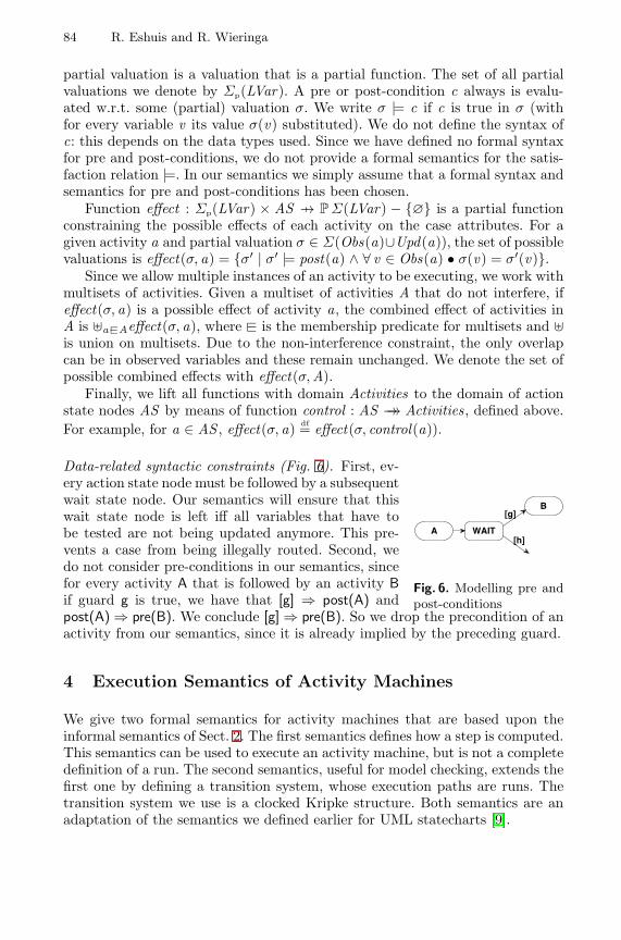
84 R. Eshuis and R. Wieringa
partial valuation is a valuation that is a partial function. The set of all partialvaluations we denote by Σp(LVar). A pre or post-condition c always is evalu-ated w.r.t. some (partial) valuation σ. We write σ |= c if c is true in σ (withfor every variable v its value σ(v) substituted). We do not define the syntax ofc: this depends on the data types used. Since we have defined no formal syntaxfor pre and post-conditions, we do not provide a formal semantics for the satis-faction relation |=. In our semantics we simply assume that a formal syntax andsemantics for pre and post-conditions has been chosen.
Function effect : Σp(LVar) × AS 7→ P Σ(LVar) − {∅} is a partial functionconstraining the possible effects of each activity on the case attributes. For agiven activity a and partial valuation σ ∈ Σ(Obs(a)∪Upd(a)), the set of possiblevaluations is effect(σ, a) = {σ′ | σ′ |= post(a) ∧ ∀ v ∈ Obs(a) • σ(v) = σ′(v)}.
Since we allow multiple instances of an activity to be executing, we work withmultisets of activities. Given a multiset of activities A that do not interfere, ifeffect(σ, a) is a possible effect of activity a, the combined effect of activities inA is ]a−@Aeffect(σ, a), where −@ is the membership predicate for multisets and ]is union on multisets. Due to the non-interference constraint, the only overlapcan be in observed variables and these remain unchanged. We denote the set ofpossible combined effects with effect(σ,A).
Finally, we lift all functions with domain Activities to the domain of actionstate nodes AS by means of function control : AS →→ Activities, defined above.For example, for a ∈ AS , effect(σ, a) df= effect(σ, control(a)).
WAITA
[g]
[h]
B
Fig. 6. Modelling pre andpost-conditions
Data-related syntactic constraints (Fig. 6). First, ev-ery action state node must be followed by a subsequentwait state node. Our semantics will ensure that thiswait state node is left iff all variables that have tobe tested are not being updated anymore. This pre-vents a case from being illegally routed. Second, wedo not consider pre-conditions in our semantics, sincefor every activity A that is followed by an activity Bif guard g is true, we have that [g] ⇒ post(A) andpost(A) ⇒ pre(B). We conclude [g] ⇒ pre(B). So we drop the precondition of anactivity from our semantics, since it is already implied by the preceding guard.
4 Execution Semantics of Activity Machines
We give two formal semantics for activity machines that are based upon theinformal semantics of Sect. 2. The first semantics defines how a step is computed.This semantics can be used to execute an activity machine, but is not a completedefinition of a run. The second semantics, useful for model checking, extends thefirst one by defining a transition system, whose execution paths are runs. Thetransition system we use is a clocked Kripke structure. Both semantics are anadaptation of the semantics we defined earlier for UML statecharts [9].
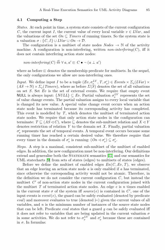
A Real-Time Execution Semantics for UML Activity Diagrams 85
4.1 Computing a Step
States. At each point in time, a system state consists of the current configurationC , the current input I , the current value of every local variable v ∈ LVar , andthe valuations of the set On ⊆ Timers of running timers. So the system state isa valuation σ : {C , I } ∪ LVar ∪ On → D.
The configuration is a multiset of state nodes Nodes → N of the activitymachine. A configuration is non-interfering, written non-interfering(C ), iff itdoes not contain interfering action state nodes:
non-interfering(C ) df⇔ ∀ a, a ′ −@ C • ¬ (a ⊥ a ′)
where as before −@ denotes the membership predicate for multisets. In the sequel,the only configurations we allow are non-interfering ones.
Input. We define input I to be a tuple (Ev , σLVp ,T , σt
p) ∈ Events × Σp(LVar) ×(AS → N)×Σp(Timers), where as before Σ(S ) denotes the set of all valuationson set S . Set Ev is the set of external events. We require that empty eventNULL is always input: {NULL} ⊆ Ev . Partial valuation σLV
p represents the setof value change events. The partial valuation assigns to every local variable thatis changed its new value. A special value change event occurs when an actionstate node has terminated because its corresponding activity has completed.This event is modelled by T , which denotes the multiset of terminated actionstate nodes. We require that only action state nodes in the configuration canterminate: T v (AS CC ), where v denotes the sub-multiset relation and X CYdenotes restriction of relation Y to the domain set X . Finally, partial valuationσt
p represents the set of temporal events. A temporal event occurs because somerunning timer has reached a certain desired value. We therefore require thatevery timer in the domain of σt
p is running: (On C σtp) ⊆ σt
p.
Steps. A step is a maximal, consistent sub-multiset of the multiset of enablededges. In addition, the new configuration must be non-interfering. Our definitionsextend and generalise both the Statemate semantics [11] and our semantics forUML statecharts [9] from sets of states (edges) to multisets of states (edges).
Before we define the multiset of enabled edges En(C ,Ev ,T ), we observethat an edge leaving an action state node a is only enabled if a has terminated,since otherwise the corresponding activity would not be atomic. Therefore, inthe definition we do not consider the current configuration C , but instead themultiset C ′ of non-action state nodes in the current configuration joined withthe multiset T of terminated action state nodes. An edge e is n times enabledin the current state σ of the system iff source(e) is contained in C ′, one of theinput events is event(e), the guard can be safely evaluated (denoted by predicateeval) and moreover evaluates to true (denoted |=) given the current values of allvariables, and n is the minimum number of instances of the source state nodesthat can be left. Predicate eval states that a guard g can be safely evaluated iffit does not refer to variables that are being updated in the current valuation σin some activities. We do not refer to σLV
p and σtp because these are contained
in σ. In formulas:
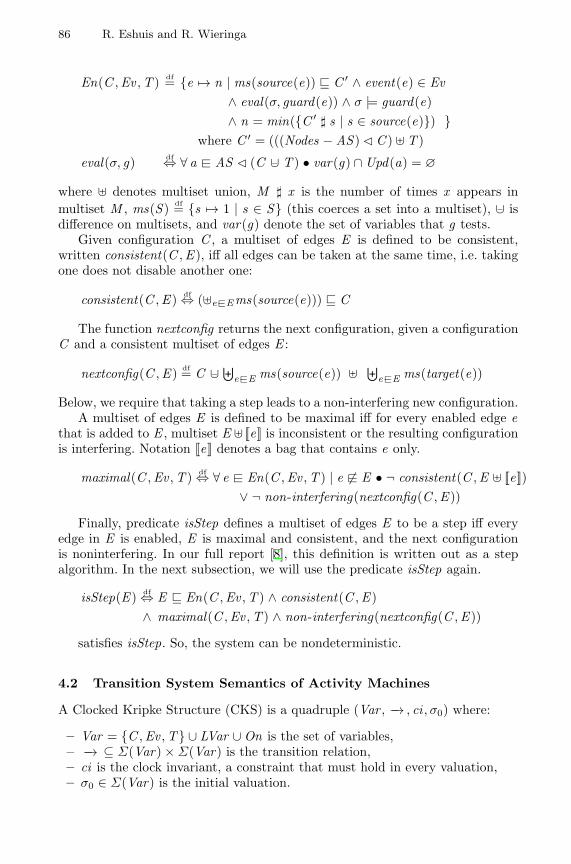
86 R. Eshuis and R. Wieringa
En(C ,Ev ,T ) df= {e 7→ n | ms(source(e)) v C ′ ∧ event(e) ∈ Ev∧ eval(σ, guard(e)) ∧ σ |= guard(e)∧ n = min({C ′ ] s | s ∈ source(e)}) }
where C ′ = (((Nodes − AS ) C C ) ] T )
eval(σ, g) df⇔ ∀ a −@ AS C (C −∪ T ) • var(g) ∩ Upd(a) = ∅
where ] denotes multiset union, M ] x is the number of times x appears inmultiset M , ms(S ) df= {s 7→ 1 | s ∈ S} (this coerces a set into a multiset), −∪ isdifference on multisets, and var(g) denote the set of variables that g tests.
Given configuration C , a multiset of edges E is defined to be consistent,written consistent(C ,E ), iff all edges can be taken at the same time, i.e. takingone does not disable another one:
consistent(C ,E ) df⇔ (]e−@Ems(source(e))) v C
The function nextconfig returns the next configuration, given a configurationC and a consistent multiset of edges E :
nextconfig(C ,E ) df= C −∪ ⊎e−@E ms(source(e)) ] ⊎
e−@E ms(target(e))
Below, we require that taking a step leads to a non-interfering new configuration.A multiset of edges E is defined to be maximal iff for every enabled edge e
that is added to E , multiset E ] [[e]] is inconsistent or the resulting configurationis interfering. Notation [[e]] denotes a bag that contains e only.
maximal(C ,Ev ,T ) df⇔ ∀ e −@ En(C ,Ev ,T ) | e 6−@ E • ¬ consistent(C ,E ] [[e]])∨ ¬ non-interfering(nextconfig(C ,E ))
Finally, predicate isStep defines a multiset of edges E to be a step iff everyedge in E is enabled, E is maximal and consistent, and the next configurationis noninterfering. In our full report [8], this definition is written out as a stepalgorithm. In the next subsection, we will use the predicate isStep again.
isStep(E ) df⇔ E v En(C ,Ev ,T ) ∧ consistent(C ,E )∧ maximal(C ,Ev ,T ) ∧ non-interfering(nextconfig(C ,E ))
satisfies isStep. So, the system can be nondeterministic.
4.2 Transition System Semantics of Activity Machines
A Clocked Kripke Structure (CKS) is a quadruple (Var , −→ , ci , σ0) where:
– Var = {C ,Ev ,T} ∪ LVar ∪ On is the set of variables,– −→ ⊆ Σ(Var) × Σ(Var) is the transition relation,– ci is the clock invariant, a constraint that must hold in every valuation,– σ0 ∈ Σ(Var) is the initial valuation.
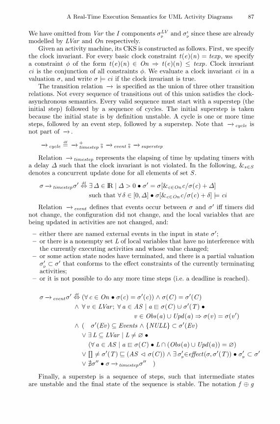
A Real-Time Execution Semantics for UML Activity Diagrams 87
We have omitted from Var the I components σLVp and σt
p since these are alreadymodelled by LVar and On respectively.
Given an activity machine, its CKS is constructed as follows. First, we specifythe clock invariant. For every basic clock constraint t(e)(n) = texp, we specifya constraint φ of the form t(e)(n) ∈ On ⇒ t(e)(n) ≤ texp. Clock invariantci is the conjunction of all constraints φ. We evaluate a clock invariant ci in avaluation σ, and write σ |= ci if the clock invariant is true.
The transition relation −→ is specified as the union of three other transitionrelations. Not every sequence of transitions out of this union satisfies the clock-asynchronous semantics. Every valid sequence must start with a superstep (theinitial step) followed by a sequence of cycles. The initial superstep is takenbecause the initial state is by definition unstable. A cycle is one or more timesteps, followed by an event step, followed by a superstep. Note that −→ cycle isnot part of −→ .
−→ cycledf= −→ +
timestepo9 −→ event o
9 −→ superstep
Relation −→ timestep represents the elapsing of time by updating timers witha delay ∆ such that the clock invariant is not violated. In the following, &s∈Sdenotes a concurrent update done for all elements of set S .
σ −→ timestepσ′ df⇔ ∃∆ ∈ IR | ∆ > 0 • σ′ = σ[&c∈Onc/σ(c) + ∆]such that ∀ δ ∈ [0, ∆] • σ[&c∈Onc/σ(c) + δ] |= ci
Relation −→ event defines that events occur between σ and σ′ iff timers didnot change, the configuration did not change, and the local variables that arebeing updated in activities are not changed, and:
– either there are named external events in the input in state σ′;– or there is a nonempty set L of local variables that have no interference with
the currently executing activities and whose value changed;– or some action state nodes have terminated, and there is a partial valuation
σ′p ⊂ σ′ that conforms to the effect constraints of the currently terminating
activities;– or it is not possible to do any more time steps (i.e. a deadline is reached).
σ −→ eventσ′ df⇔ (∀ c ∈ On • σ(c) = σ′(c)) ∧ σ(C ) = σ′(C )
∧ ∀ v ∈ LVar ; ∀ a ∈ AS | a −@ σ(C ) −∪ σ′(T ) •v ∈ Obs(a) ∪ Upd(a) ⇒ σ(v) = σ(v ′)
∧ ( σ′(Ev) ⊆ Events ∧ {NULL} ⊂ σ′(Ev)∨ ∃L ⊆ LVar | L 6= ∅ •
(∀ a ∈ AS | a −@ σ(C ) • L ∩ (Obs(a) ∪ Upd(a)) = ∅)∨ [[]] 6= σ′(T ) v (AS C σ(C )) ∧ ∃σ′
p∈effect(σ, σ′(T )) • σ′p ⊂ σ′
∨ @σ′′ • σ −→ timestepσ′′ )
Finally, a superstep is a sequence of steps, such that intermediate statesare unstable and the final state of the sequence is stable. The notation f ⊕ g
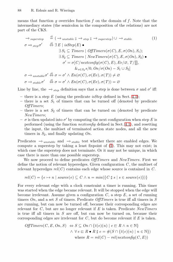
88 R. Eshuis and R. Wieringa
means that function g overrides function f on the domain of f . Note that theintermediary states (the semicolon in the composition of the relations) are notpart of the CKS.
−→ superstepdf= ( −→ unstable o
9 −→ step o9 −→ superstep) ∪ −→ stable (1)
σ −→ stepσ′ df⇔ ∃E | isStep(E ) •∃S1 ⊆ Timers | OffTimers(σ(C ),E , σ(On),S1);∃S2 ⊆ Timers | NewTimers(σ(C ),E , σ(On),S2) •
σ′ = σ[C/nextconfig(σ(C ),E ),Ev/∅,T/[[]],&s∈S2s/0,On/σ(On) − S1 ∪ S2]
σ −→ unstableσ′ df⇔ σ = σ′ ∧ En(σ(C ), σ(Ev), σ(T )) 6= ∅
σ −→ stableσ′ df⇔ σ = σ′ ∧ En(σ(C ), σ(Ev), σ(T )) = ∅
Line by line, the −→ step definition says that a step is done between σ and σ′ iff:
– there is a step E (using the predicate isStep defined in Sect. 4.1);– there is a set S1 of timers that can be turned off (denoted by predicate
OffTimers;– there is a set S2 of timers that can be turned on (denoted by predicate
NewTimers;– σ is then updated into σ′ by computing the next configuration when step E is
performed (using the function nextconfig defined in Sect. 4.1), and resettingthe input, the multiset of terminated action state nodes, and all the newtimers in S2, and finally updating On.
Predicates −→ unstable and −→ stable test whether there are enabled edges. Wecompute a superstep by taking a least fixpoint of (1). This may not exist; inwhich case the superstep does not terminate. Or it may not be unique, in whichcase there is more than one possible superstep.
We now proceed to define predicates OffTimers and NewTimers. First wedefine the notion of relevant hyperedges. Given configuration C , the multiset ofrelevant hyperedges rel(C ) contains each edge whose source is contained in C .
rel(C ) = {e 7→ n | source(e) ⊆ C ∧ n = min({C ] s | s ∈ source(e)})}For every relevant edge with a clock constraint a timer is running. This timerwas started when the edge became relevant. It will be stopped when the edge willbecome irrelevant. Assume given a configuration C , a step E , a set of runningtimers On, and a set S of timers. Predicate OffTimers is true iff all timers in Sare running, but can now be turned off, because their corresponding edges arerelevant for C , but are no longer relevant if E is taken. Predicate NewTimersis true iff all timers in S are off, but can now be turned on, because theircorresponding edges are irrelevant for C , but do become relevant if E is taken.
OffTimers(C ,E ,On,S ) ⇔ S ⊆ On ∩ {t(e)(n) | e −@ R ∧ n ∈ N}∧ ∀ e −@ R • R ] e = #(S ∩ {t(e)(n) | n ∈ N})
where R = rel(C ) − rel(nextconfig(C ,E ))
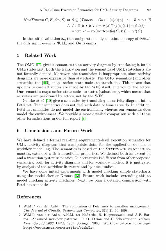
A Real-Time Execution Semantics for UML Activity Diagrams 89
NewTimers(C ,E ,On,S ) ⇔ S ⊆ (Timers − On) ∩ {t(e)(n) | e −@ R ∧ n ∈ N}∧ ∀ e −@ R • R ] e = #(S ∩ {t(e)(n) | n ∈ N})
where R = rel(nextconfig(C ,E )) − rel(C )
In the initial valuation σ0, the configuration only contains one copy of initial ,the only input event is NULL, and On is empty.
5 Related Work
The OMG [16] gives a semantics to an activity diagram by translating it into aUML statechart. Both the translation and the semantics of UML statecharts arenot formally defined. Moreover, the translation is inappropriate, since activitydiagrams are more expressive than statecharts. The OMG semantics (and othersemantics too [4,5]) maps action state nodes to transitions. This means thatupdates to case attributes are made by the WFS itself, and not by the actors.Our semantics maps action state nodes to states (valuations), which means thatactivities are performed by actors, not by the WFS.
Gehrke et al. [10] give a semantics by translating an activity diagram into aPetri net. Their semantics does not deal with data or time as we do. In addition,Petri net semantics do not model the environment, whereas our semantics doesmodel the environment. We provide a more detailed comparison with all theseother formalisations in our full report [8].
6 Conclusions and Future Work
We have defined a formal real-time requirements-level execution semantics forUML activity diagrams that manipulate data, for the application domain ofworkflow modelling. The semantics is based on the Statemate statechart se-mantics, extended with transactional properties. We defined both an executionand a transition system semantics. Our semantics is different from other proposedsemantics, both for activity diagrams and for workflow models. It is motivatedby analysis of the workflow literature and by case studies.
We have done initial experiments with model checking simple statechartsusing the model checker Kronos [13]. Future work includes extending this tomodel checking activity machines. Next, we plan a detailed comparison withPetri net semantics.
References
1. W.M.P. van der Aalst. The application of Petri nets to workflow management.The Journal of Circuits, Systems and Computers, 8(1):21–66, 1998.
2. W.M.P. van der Aalst, A.H.M. ter Hofstede, B. Kiepuszewski, and A.P. Bar-ros. Advanced workflow patterns. In O. Etzion and P. Scheuermann, editors,Proc. CoopIS 2000, LNCS 1901. Springer, 2000. Workflow pattern home page:http://www.mincom.com/mtrspirt/workflow.
90 R. Eshuis and R. Wieringa
3. G. Berry and G. Gonthier. The Esterel synchronous programming language:design, semantics, implementation. Sci. of Comp. Prog., 19(2):87–152, 1992.
4. C. Bolton and J. Davies. Activity graphs and processes. In W. Grieskamp, T. San-ten, and B. Stoddart, editors, Proc. Integrated Formal Methods 2000, LNCS 1945.Springer, 2000.
5. E. Borger, A. Cavarra, and E. Riccobene. An ASM Semantics for UML ActivityDiagrams. In T. Rus, editor, Proc. Algebraic Methodology and Software Technology,8th International Conference, AMAST 2000, LNCS 1826. Springer, 2000.
6. F. Dehne, R. Wieringa, and H. van de Zandschulp. Toolkit for conceptual modeling(TCM) — user’s guide and reference. Technical report, University of Twente, 2000.http://www.cs.utwente.nl/˜tcm.
7. R. Elmasri and S. Navathe. Fundamentals of Database Systems. Benjamins/Cum-mings, Redwood City, 1989.
8. R. Eshuis and R. Wieringa. A formal semantics for UML activity diagrams, 2001.Available at http://www.cs.utwente.nl/˜eshuis/adsem.ps.
9. R. Eshuis and R. Wieringa. Requirements-level semantics for UML statecharts.In S.F. Smith and C.L. Talcott, editors, Formal Methods for Open Object-BasedDistributed Systems IV, pages 121–140. Kluwer Academic Publishers, 2000.
10. T. Gehrke, U. Goltz, and H. Wehrheim. The dynamic models of UML: Towards asemantics and its application in the development process. Hildesheimer Informatik-Bericht 11/98, 1998.
11. D. Harel and A. Naamad. The STATEMATE Semantics of Statecharts. ACMTransactions on Software Engineering and Methodology, 5(4):293–333, 1996.
12. D. Harel and A. Pnueli. On the development of reactive systems. In K. R. Apt,editor, Logics and Models of Concurrent Systems, NATO/ASI 13. Springer, 1985.
13. D. N. Jansen and R. J. Wieringa. Extending CTL with actions and real-time. InProc. International Conference on Temporal Logic 2000, 2000.
14. F. Leymann and D. Roller. Production Workflow — Concepts and Techniques.Prentice Hall, 2000.
15. S. McMenamin and J. Palmer. Essential Systems Analysis. Yourdon Press, NewYork, New York, 1984.
16. OMG. Unified Modeling Language version 1.3. OMG, July 1999.17. J. M. Spivey. The Z Notation: A Reference Manual. Prentice-Hall, 1992.18. D. Wodtke and G. Weikum. A formal foundation for distributed workflow execution
based on state charts. In F. N. Afrati and P. Kolaitis, editors, 6th InternationalConference on Database Theory (ICDT), LNCS 1186. Springer, 1997.
19. Workflow Management Coalition. Workflow management coalition specification —terminology & glossary (WFMC-TC-1011), 1999. http://www.wfmc.org.
A CSP View on UML-RT Structure Diagrams
Clemens Fischer, Ernst-Rudiger Olderog, and Heike Wehrheim
Universitat OldenburgFachbereich Informatik
Postfach 2503, D–26111 Oldenburg, GermanyFax: +49 441 7982965
{fischer,olderog,wehrheim}@informatik.uni-oldenburg.de
Abstract. UML-RT is an extension of UML for modelling embeddedreactive and real-time software systems. Its particular focus lies on sy-stem descriptions on the architectural level, defining the overall systemstructure. In this paper we propose to use UML-RT structure diagramstogether with the formal method CSP-OZ combining CSP and Object-Z.While CSP-OZ is used for specifying the system components themselves(by CSP-OZ classes), UML-RT diagrams provide the architecture de-scription. Thus the usual architecture specification in terms of the CSPoperators parallel composition, renaming and hiding is replaced by agraphical description. To preserve the formal semantics of CSP-OZ spe-cifications, we develop a translation from UML-RT structure diagramsto CSP. Besides achieving a more easily accessible, graphical architec-ture modelling for CSP-OZ, we thus also give a semantics to UML-RTstructure diagrams.
1 Introduction
Graphical modelling notations are becoming increasingly important in the designof industrial software systems. The Unified Modelling Language (UML [2,13]),being standardised by the Object Management Group OMG, is the most promi-nent member of a number of graphical modelling notations for object-orientedanalysis and design. UML-RT [16] is a UML profile proposed as a modellinglanguage for embedded real-time software systems. Although the name RT re-fers to real-time, UML-RT’s main extension concerns facilities for describing thearchitecture of distributed interconnected systems. UML-RT defines three newconstructs for modelling structure: capsules, ports and connectors, and employsthese constructs within UML’s collaboration diagrams to obtain an architecturedescription. The advantage of UML-RT, like UML, is the graphical representa-tion of the modelled system. However, it lacks a precise semantics.
A different approach to the specification of software systems is taken whena formal method is used as a modelling language. In contrast to UML, formalmethods have a precise semantics, but mostly do not offer graphical means ofspecification. A joint usage of formal methods and graphical modelling languagescould thus benefit from the advantages and overcome the deficiencies of each
H. Hussmann (Ed.): FASE 2001, LNCS 2029, pp. 91–108, 2001.c© Springer-Verlag Berlin Heidelberg 2001
92 C. Fischer, E.-R. Olderog, and H. Wehrheim
method. A number of proposals for combining UML with a formal method havealready been made (e.g. [3,4,10,14]). This paper makes another contribution inthis field, focusing on one particular aspect of system modelling, the architecturedescriptions.
The formal method we employ is CSP-OZ [5,6], a combination of the processalgebra CSP [9,15] and the specification language Object-Z [17,18]. The workpresented in this paper can be seen as a first step towards an integration of UMLand CSP-OZ. CSP-OZ has several features which makes it a suitable candidatefor a formal method supporting UML. To name just two: it is an object-orientednotation (with concepts like classes, instantiation and inheritance), and, likeUML, it combines a formalism for describing static aspects (Z) with one fordescribing the dynamic behaviour (CSP).
CSP-OZ specifications typically consist of three parts: first, some basic de-finitions of e.g. types are made; second, classes are defined, and finally, thesystem architecture (components and their interconnections) is fixed. All ingre-dients which usually appear in UML class descriptions can be found in CSP-OZclasses: attributes, methods and inherited superclasses are declared, associationscan be modelled by using attributes with type of another class. Furthermore, onepart of a CSP-OZ class specifies the dynamic behaviour of the class, which, inUML, is usually given by a separate diagram, e.g. a state chart. In contrast toUML, CSP-OZ uses the CSP process-algebraic notation for this purpose. Thesystem architecture is given by instantiating the classes into a suitable numberof objects and combining them using the CSP operators for parallel composition,hiding and renaming. To clarify this overall structure of the system, often somesort of ad-hoc connection diagram is drawn. But these diagrams only serve asan illustration of the CSP architecture description; neither is the form of thediagrams fixed in any way, nor do they have a formal semantics. Hence theycannot actually replace the CSP description.
For the integration of CSP-OZ and UML we start here with this last part ofCSP-OZ specifications. Defining the system architecture in the above describedsense is exactly the intended purpose of UML-RT structure diagrams. Our propo-sal in this paper is therefore to replace the textual CSP architecture descriptionsby UML-RT structure diagrams. To preserve the precision of a formal methodwe fix the syntax and semantics of these diagrams. The advantages are twofold:UML-RT provides us with a widely accepted graphical specification technique fordefining architectures, and additionally a formal semantics for UML-RT struc-ture diagrams in the setting of distributed communicating systems is achieved.For the other main ingredients of CSP-OZ specifications, the classes, we envi-sage an integration with UML in the following way: CSP-OZ classes are splitinto a static part, with an appropriate representation by UML class diagrams,and a dynamic part, with a representation by e.g. an activity diagram or a statechart. However, in this paper we are only concerned with obtaining a graphicaldescription of the architecture specification.
Technically, the use of UML-RT diagrams within CSP-OZ is achieved bythe following two issues: a formalisation of the syntax of UML-RT diagrams
A CSP View on UML-RT Structure Diagrams 93
with Object-Z and a formalisation of their semantics using the CSP operatorsfor parallel composition, renaming and hiding. The major difficulty in giving asemantics to UML-RT diagrams is the treatment of the multi-object notation ofUML: a component may communicate with a multi-object (a number of instancesof the same class) over a single channel. In this case some kind of addressinghas to be introduced to achieve communication with a particular instance, i.e.the channel additionally has to carry addresses of receivers. Since the need forintroducing an addressing mechanism in communication is already visible inthe architecture description, the translation also has to take addressing intoaccount. This is solved by introducing special address parameters for processesand carrying out appropriate renamings on channel names of components.
The case study in Section 4 demonstrates the usefulness of the multi-objectnotation in a real-life application. In our applications the basic capsules in UML-RT structure diagrams stand for CSP-OZ classes or simply CSP processes. Ho-wever, in this paper the details of CSP-OZ are not important. Here we only needthe architectural operators of CSP that allow us to connect CSP-OZ classes orCSP processes: parallel composition, renaming and hiding.For UML-RT the results of this paper are a contribution to its formal semantics.We nevertheless believe that this is not the only possible interpretation (in parti-cular since we only use a very simple form of protocols allowing for synchronouscommunication over one channel); in a different setting a different semanticsmight be conceivable. For CSP and CSP-OZ the benefit is a precise type of dia-gram for describing the system architecture, replacing the informal connectiondiagrams that appear in books on process algebra like [9], viz. UML-RT struc-ture diagrams. Particularly interesting is the use of multi-objects of UML-RTfor a concise description of iterated CSP operators.The paper is organised as follows. The next section gives a short introductionto the specific constructs of UML-RT and formalises the syntax of structurediagrams using Object-Z. Section 3 defines the semantics of these diagrams by atranslation to CSP. We illustrate our approach by some smaller examples and,in Section 4, by the case study of an automatic manufacturing system. Theconclusion summarises our work and discusses some related approaches.
2 UML-RT
Currently, the UML, as standardised by the OMG, is the most widely usedobject-oriented modelling language. UML-RT (UML for Real-Time Systems)[16] is an extension of UML designed for describing architectures of embeddedreal-time systems. The emphasis of this extension lies on the modelling of thestructure of distributed systems, no particular real-time features are added toUML’s possibilities. The extension uses standard UML tailoring mechanisms likestereotypes and tagged values.
In the following, we briefly describe UML-RT and give some small examples.UML-RT defines three constructs for modelling the structure of distributed sy-stems:
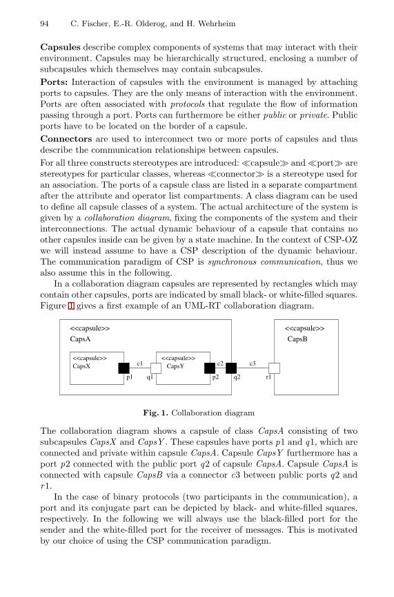
94 C. Fischer, E.-R. Olderog, and H. Wehrheim
Capsules describe complex components of systems that may interact with theirenvironment. Capsules may be hierarchically structured, enclosing a number ofsubcapsules which themselves may contain subcapsules.Ports: Interaction of capsules with the environment is managed by attachingports to capsules. They are the only means of interaction with the environment.Ports are often associated with protocols that regulate the flow of informationpassing through a port. Ports can furthermore be either public or private. Publicports have to be located on the border of a capsule.Connectors are used to interconnect two or more ports of capsules and thusdescribe the communication relationships between capsules.For all three constructs stereotypes are introduced: �capsule� and �port� arestereotypes for particular classes, whereas �connector� is a stereotype used foran association. The ports of a capsule class are listed in a separate compartmentafter the attribute and operator list compartments. A class diagram can be usedto define all capsule classes of a system. The actual architecture of the system isgiven by a collaboration diagram, fixing the components of the system and theirinterconnections. The actual dynamic behaviour of a capsule that contains noother capsules inside can be given by a state machine. In the context of CSP-OZwe will instead assume to have a CSP description of the dynamic behaviour.The communication paradigm of CSP is synchronous communication, thus wealso assume this in the following.
In a collaboration diagram capsules are represented by rectangles which maycontain other capsules, ports are indicated by small black- or white-filled squares.Figure 1 gives a first example of an UML-RT collaboration diagram.
<<capsule>> <<capsule>>
<<capsule>> <<capsule>>
p1 p2 q2q1 r1
c1 c2 c3
CapsA CapsB
CapsX CapsY
Fig. 1. Collaboration diagram
The collaboration diagram shows a capsule of class CapsA consisting of twosubcapsules CapsX and CapsY . These capsules have ports p1 and q1, which areconnected and private within capsule CapsA. Capsule CapsY furthermore has aport p2 connected with the public port q2 of capsule CapsA. Capsule CapsA isconnected with capsule CapsB via a connector c3 between public ports q2 andr1.
In the case of binary protocols (two participants in the communication), aport and its conjugate part can be depicted by black- and white-filled squares,respectively. In the following we will always use the black-filled port for thesender and the white-filled port for the receiver of messages. This is motivatedby our choice of using the CSP communication paradigm.
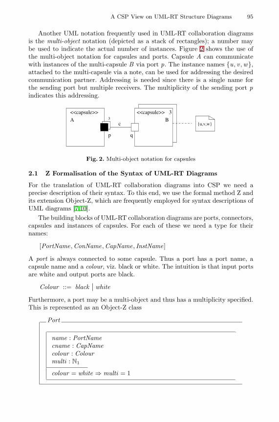
A CSP View on UML-RT Structure Diagrams 95
Another UML notation frequently used in UML-RT collaboration diagramsis the multi-object notation (depicted as a stack of rectangles); a number maybe used to indicate the actual number of instances. Figure 2 shows the use ofthe multi-object notation for capsules and ports. Capsule A can communicatewith instances of the multi-capsule B via port p. The instance names {u, v ,w},attached to the multi-capsule via a note, can be used for addressing the desiredcommunication partner. Addressing is needed since there is a single name forthe sending port but multiple receivers. The multiplicity of the sending port pindicates this addressing.
������
������
<<capsule>> 3<<capsule>>
p q
cA 3 B
{u,v,w}
Fig. 2. Multi-object notation for capsules
2.1 Z Formalisation of the Syntax of UML-RT Diagrams
For the translation of UML-RT collaboration diagrams into CSP we need aprecise description of their syntax. To this end, we use the formal method Z andits extension Object-Z, which are frequently employed for syntax descriptions ofUML diagrams [7,10].
The building blocks of UML-RT collaboration diagrams are ports, connectors,capsules and instances of capsules. For each of these we need a type for theirnames:
[PortName,ConName,CapName, InstName]
A port is always connected to some capsule. Thus a port has a port name, acapsule name and a colour, viz. black or white. The intuition is that input portsare white and output ports are black.
Colour ::= black | white
Furthermore, a port may be a multi-object and thus has a multiplicity specified.This is represented as an Object-Z class
Port
name : PortNamecname : CapNamecolour : Colourmulti : N1
colour = white ⇒ multi = 1
96 C. Fischer, E.-R. Olderog, and H. Wehrheim
with a state consisting of the attributes cname, colour and multi. We assume thatwhite ports (the receivers) always have multiplicity one. The particular receiverof a message is solely determined by the sender. This restriction is not enforcedby UML-RT, but chosen with our particular setting with CSP communication inmind. A port with multiplicity 1 is called single port and a port with multiplicitygreater than 1 is called a multi-port.
A connector comprises a name and a finite set of ports. For simplicity weassume that every connector combines exactly two ports. Thus we only considerthe case of binary protocols or point-to-point communication. The name of aconnector is not always given in UML diagrams, but we assume that some uniquedefault name for every connector can be generated. This is represented by anObject-Z class
Connector
name : ConNameports : F Port
#ports = 2
where the state has the attributes name and ports.In UML-RT system components are represented by capsules. We distinguish
between basic, compound and multi-object capsules. This is formalised usingObject-Z by defining a base class Capsule which is then extended via inhe-ritance to subclasses CompCapsule and MultiCapsule. A basic capsule will betranslated into a CSP-OZ class or simply a CSP process. It usually has a numberof ports to be able to communicate with its environment. A compound capsulehas in addition some subcapsules linked by connectors. A multi-object capsuleis obtained from a basic or compound capsule by adding a multiplicity.
Each capsule has a name. We assume that capsule names are unique, i.e. thereexists an injective function C from capsules names to capsules (and all theirsubclasses denoted by the operator ↓):
C : CapName 7� ↓ Capsule [Capsule and all its subclasses]
∀na : dom C • na = C(na).name [C respects capsule names]
The function C is a partial function because not every capsule name has to beused in a given design. We also assume port names and connector names to beunique, which can be similarly fixed by defining partial functions P for portsand N for connectors.
A capsule itself has a name and a finite set of ports that are considered aspublic, i.e. accessible from the environment. This is represented as an Object-Zbase class where the state has the attributes name and ports:
A CSP View on UML-RT Structure Diagrams 97
Capsule
name : CapNameports : F Port
∀ p : ports • p.cname = name
The consistency condition requires that all ports of a capsule refer to that cap-sule.
A compound capsule extends a given capsule by an inner structure consistingof a finite set of subcapsules, referenced by names, and a finite set of connectors.We use therefore the inheritance notation of Object-Z1:
CompCapsuleinherit Capsule
scnames : F CapName [ names of subcapsules]conn : F Connector [inner connectors]
∀ c : conn • c.ports ⊆ ports ∪ ⋃{sn : scnames • C(sn).ports} [1]∀ c1, c2 : conn • c1.ports ∩ c2.ports 6= ∅ ⇒ c1 = c2 [2]∀ c : conn • ∀ p, p′ : c.ports • p 6= p′ ⇒ p.cname 6= p′.cname [3]∀ c : conn • ∀ p, p′ : c.ports • ( p 6= p′ ⇒
(p ∈ ports ⇒ p.multi = p′.multi ∧ p.colour = p′.colour) [4]∧
(p, p′ 6∈ ports ⇒ p.colour 6= p′.colour ∧ [5]((p.multi = 1 ∧ p′.multi = C(p.cname).multi)
∨(p′.multi = 1 ∧ p.multi = C(p′.cname).multi)) ) )
The ports of the subcapsules are treated as private, i.e. hidden form the environ-ment. The connectors link these private ports of the subcapsules to each otheror to the public ports of the whole capsule. The predicates state consistencyconditions for compound capsules:
– connectors can only connect ports given in the capsule (condition 1),– any two connectors with a common port are identical, i.e. connectors repre-
sent point-to-point connections without fan-out (condition 2),– connectors may only connect ports of different capsules (condition 3).
1 Inheritance in Object-Z is syntactically expressed by simple inclusion of a class.Semantically inheritance is expressed by signature extension and logical conjunction.
98 C. Fischer, E.-R. Olderog, and H. Wehrheim
Furthermore the multiplicities of the ports of a connector have to match:
– if one port of the connector is public, the multiplicities and colours of bothports of the connector coincide (condition 4),
– if both ports of the connector are private, the colours of the ports differ,one is a single port and the other one has a multiplicity that coincides withthe multiplicity of the subcapsule of the single port (condition 5, see alsoFigure 2). Note that this covers the case that both ports and hence boththeir subcapsules are single ones.
A multi-capsule inherits all attributes from the base class Capsule and further-more contains another capsule (the one which is multiplied), the multiplicityand the names of the instances (we assume that these names are either given inthe diagram, e.g. by attaching a note to the multi-capsule, or can be generated).Using inheritance this can be represented as follows:
MultiCapsuleinherit Capsule
scname : CapNamemulti : N1inames : F InstName
#inames = multi
Starting from ports, connectors and capsules, systems can be built up. A systemis defined as an outermost capsule.
3 Translating UML-RT Diagrams to CSP
UML-RT structure diagrams give a graphical description of the architecture ofsystems, their components and interconnections. The Object-Z formalisation sofar fixes the valid syntactic structures of these diagrams. For giving a formalsemantics of the behavioural aspects of the diagrams, we use another formalmethod which is particularly suited for the description of distributed communi-cating systems: the process algebra CSP [9,15].
3.1 A Brief Re-cap of CSP
CSP is a formal method for specifying and reasoning about processes. CSPdescribes a system as a number of processes, possibly running in parallel andsynchronously communicating over named channels. Each process is built oversome set of communication events, using operators like sequential compositionor choice to construct more complex processes. For describing the architectureof systems the operators parallel composition, hiding and renaming are used.
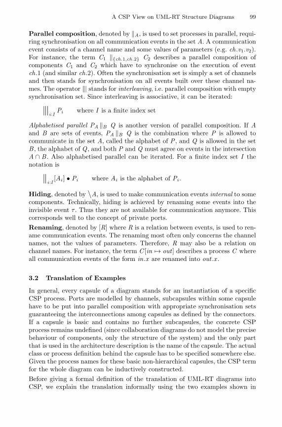
A CSP View on UML-RT Structure Diagrams 99
Parallel composition, denoted by ‖A, is used to set processes in parallel, requi-ring synchronisation on all communication events in the set A. A communicationevent consists of a channel name and some values of parameters (e.g. ch.v1.v2).For instance, the term C1 ‖{ch.1,ch.2} C2 describes a parallel composition ofcomponents C1 and C2 which have to synchronise on the execution of eventch.1 (and similar ch.2). Often the synchronisation set is simply a set of channelsand then stands for synchronisation on all events built over these channel na-mes. The operator ‖| stands for interleaving, i.e. parallel composition with emptysynchronisation set. Since interleaving is associative, it can be iterated:
‖|i:I Pi where I is a finite index set
Alphabetised parallel PA ‖B Q is another version of parallel composition. If Aand B are sets of events, PA ‖B Q is the combination where P is allowed tocommunicate in the set A, called the alphabet of P , and Q is allowed in the setB , the alphabet of Q , and both P and Q must agree on events in the intersectionA ∩ B . Also alphabetised parallel can be iterated. For a finite index set I thenotation is
‖i:I[Ai ] • Pi where Ai is the alphabet of Pi .
Hiding, denoted by \A, is used to make communication events internal to somecomponents. Technically, hiding is achieved by renaming some events into theinvisible event τ . Thus they are not available for communication anymore. Thiscorresponds well to the concept of private ports.Renaming, denoted by [R] where R is a relation between events, is used to ren-ame communication events. The renaming most often only concerns the channelnames, not the values of parameters. Therefore, R may also be a relation onchannel names. For instance, the term C [in 7→ out ] describes a process C whereall communication events of the form in.x are renamed into out .x .
3.2 Translation of Examples
In general, every capsule of a diagram stands for an instantiation of a specificCSP process. Ports are modelled by channels, subcapsules within some capsulehave to be put into parallel composition with appropriate synchronisation setsguaranteeing the interconnections among capsules as defined by the connectors.If a capsule is basic and contains no further subcapsules, the concrete CSPprocess remains undefined (since collaboration diagrams do not model the precisebehaviour of components, only the structure of the system) and the only partthat is used in the architecture description is the name of the capsule. The actualclass or process definition behind the capsule has to be specified somewhere else.Given the process names for these basic non-hierarchical capsules, the CSP termfor the whole diagram can be inductively constructed.Before giving a formal definition of the translation of UML-RT diagrams intoCSP, we explain the translation informally using the two examples shown in
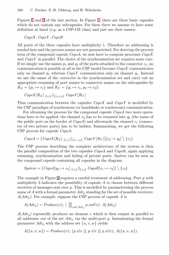
100 C. Fischer, E.-R. Olderog, and H. Wehrheim
Figures 1 and 2 of the last section. In Figure 1, there are three basic capsuleswhich do not contain any subcapsules. For these three we assume to have somedefinition at hand (e.g. as a CSP-OZ class) and just use their names:
CapsX ,CapsY ,CapsB
All ports of the three capsules have multiplicity 1. Therefore no addressing isneeded here and the process names are not parametrised. For deriving the processterm of the compound capsule CapsA, we now have to compose processes CapsXand CapsY in parallel. The choice of the synchronisation set requires some care.If we simply use the names p1 and q1 of the ports attached to the connector c1, nocommunication is possible at all in the CSP model because CapsX communicatesonly on channel p1 whereas CapsY communicates only on channel q1. Insteadwe use the name of the connector in the synchronisation set and carry out anappropriate renaming of port names to connector names on the subcapsules byRX = {p1 7→ c1} and RY = {q1 7→ c1, p2 7→ c2}:
CapsX [RX ] {c1} ||{c1,c2} CapsY [RY ]
Thus communication between the capsules CapsX and CapsY is modelled bythe CSP paradigm of synchronous (or handshake or rendezvous) communication.
For obtaining the process for the compound capsule CapsA two more opera-tions have to be applied: the channel c2 has to be renamed into q2 (the name ofthe public port on the border of CapsA) and afterwards the channel c1 (connec-tor of two private ports) has to be hidden. Summarising, we get the followingCSP process for capsule CapsA:
CapsA = (CapsX [RX ] {c1} ||{c1,c2} CapsY [RY ])[c2 7→ q2] \ {c1}The CSP process describing the complete architecture of the system is thenthe parallel composition of the two capsules CapsA and CapsB , again applyingrenaming, synchronisation and hiding of private ports. System can be seen asthe compound capsule containing all capsules in the diagram.
System = (CapsA[q2 7→ c3] {c3}‖{c3} CapsB [r1 7→ c3]) \ {c3}
The example in Figure 2 requires a careful treatment of addressing. Port p withmultiplicity 3 indicates the possibility of capsule A to choose between differentreceivers of messages sent over p. This is modelled by parameterising the processname of A with a formal parameter Adrp standing for the set of possible receivers:A(Adrp). For example, suppose the CSP process of capsule A is
A(Adrp) = Produce(e); ( ‖|out:Adrpp.out !e); A(Adrp)
A(Adrp) repeatedly produces an element e which is then output in parallel toall addresses out of the set Adrp via the multi-port p. Instantiating the formalparameter Adrp with the address set {u, v ,w} yields
A({u, v ,w}) = Produce(e); (p.u!e ‖| p.v !e ‖| p.w !e); A({u, v ,w}).
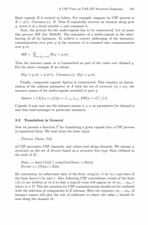
A CSP View on UML-RT Structure Diagrams 101
Basic capsule B is treated as before. For example, suppose its CSP process isB = q?x ; Consume(x ); B . Thus B repeatedly receives an element along portq , stores it in a local variable x and consumes it.
Next, the process for the multi-capsule has to be constructed. Let us namethis process MB (for MultiB). The semantics of a multi-capsule is the inter-leaving of all its instances. To achieve a correct addressing of the instances,communication over port q in the instance in is renamed into communicationover q .in:
MB = ‖|in:{u,v ,w} B [q 7→ q .in]
Thus the instance name in is transmitted as part of the value over channel q .For the above example B we obtain
B [q 7→ q .in] = q .in?x ; Consume(x ); B [q 7→ q .in].
Finally, compound capsule System is constructed. This requires an instan-tiation of the address parameter of A with the set of receivers {u, v ,w}, theinstance names of the multi-capsule attached to port p.
System = (A({u, v ,w})[p 7→ c] {c} ||{c} MB [q 7→ c]) \ {c}
Capsule A may now use the instance names u, v ,w as parameters for channel pand thus send messages to particular instances.
3.3 Translation in General
Now we present a function T for translating a given capsule into a CSP processin equational form. We start from the basic types
[Process,Chans,Val ]
of CSP processes, CSP channels, and values sent along channels. We assume astructure on the set of Events based on a recursive free type Data (defined inthe style of Z):
Data ::= basic〈〈Val〉〉 | comp〈〈InstName × Data〉〉Events == Chans × Data
By convention, we abbreviate data of the form comp(in, v) by in.v and data ofthe form basic(v) by just v . Also, following CSP conventions, events of the form(ch, d) are written as ch.d so that a typical event will appear as ch.in1.....inm .vwhere m ∈ N. This dot notation for CSP communications should not be confusedwith the selection of components in Z schemas. Here the sequence in1.....inm ofinstance names will play the role of addresses to where the value v should besent along the channel ch.
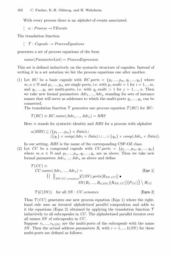
102 C. Fischer, E.-R. Olderog, and H. Wehrheim
With every process there is an alphabet of events associated:
α : Process → PEvents
The translation function
T : Capsule → ProcessEquations
generates a set of process equations of the form
name(ParameterList) = ProcessExpression
This set is defined inductively on the syntactic structure of capsules. Instead ofwriting it in a set notation we list the process equations one after another.
(1) Let BC be a basic capsule with BC .ports = {p1, ..., pm , q1, ..., qn} wherem,n ∈ N and p1, ..., pm are single ports, i.e. with pi .multi = 1 for i = 1, ...m,and q1, ..., qn are multi-ports, i.e. with qj .multi > 1 for j = 1, ...,n. Thenwe take new formal parameters Adr1, ...,Adrn standing for sets of instancenames that will serve as addresses to which the multi-ports q1, ..., qn can beconnected.The translation function T generates one process equation T (BC ) for BC :
T (BC ) ≡ BC .name(Adr1, ...,Adrn) = RHS
Here ≡ stands for syntactic identity and RHS for a process with alphabet
α(RHS ) ⊆ ({p1, ..., pm} × Data)∪({q1} × comp(Adr1 × Data) ∪ ... ∪ {qn} × comp(Adrn × Data)).
In our setting, RHS is the name of the corresponding CSP-OZ class.(2) Let CC be a compound capsule with CC .ports = {p1, ..., pm , q1, ..., qn}
where m,n ∈ N and p1, ..., pm , q1, ..., qn are as above. Then we take newformal parameters Adr1, ...,Adrn as above and define
T (CC ) ≡CC .name(Adr1, ...,Adrn) = [Eqn 1]
(( ‖SN :CC .scnames[C(SN ).ports[RSN ,CC ]] •SN (B1, ...,Bk(SN ))[RSN ,CC ])[PCC ]) \ HCC
T (C(SN )) for all SN : CC .scnames [Eqns 2]
Thus T (CC ) generates one new process equation (Eqn 1) where the right-hand side uses an iterated alphabetised parallel composition and adds toit the equations (Eqns 2) obtained by applying the translation function Tinductively to all subcapsules in CC . The alphabetised parallel iterates overall names SN of subcapsules in CC .Suppose r1, ..., rk(SN ) are the multi-ports of the subcapsule with the nameSN . Then the actual address parameters Bi with i = 1, ..., k(SN ) for thesemulti-ports are defined as follows:
A CSP View on UML-RT Structure Diagrams 103
– Bi = Adrpj if ri is connected to a public multi-port pj of CC– Bi = MC .inames if ri is connected to a single port pj of a multi-capsule
MC inside CCThe renaming RSN ,CC changes port names to connector names:
RSN ,CC = {pn : PortName; cn : ConName |∃ p : C(SN ).ports; c : CC .conn •p ∈ c.ports ∧ pn = p.name ∧ cn = c.name • (pn 7→ cn)}
The renaming PCC is used to rename connectors from a subcapsule to apublic port on the border of the capsule back to the name of the public port:
PCC = {cn : ConName; pn : PortName |∃ p : CC .ports; c : CC .conn •p ∈ c.ports ∧ pn = p.name ∧ cn = c.name • (cn 7→ pn)}
Finally, all remaining connector names are hidden:
HCC = {c : CC .conn • c.name}(3) Let MC be a multi-capsule with
C(MC .cname).ports = {p1, ..., pm , q1, ..., qn}where m,n ∈ N and p1, ..., pm , q1, ..., qn are as above. Again we take newformal parameters Adr1, ...,Adrn as above and define
T (MC ) ≡MC .name(Adr1, ...,Adrn) = [Eqn 1]
‖|in:MC .inamesMC .cname(Adr1, ...,Adrn)[(in)]
T (C(MC .cname))) [Eqn 2]
Thus T (MC ) generates one new process equation (Eqn 1) where the right-hand side uses an iterated interleaving operator and adds to it the equation(Eqn 2) obtained by applying the translation function T inductively to thecapsule inside MC . The interleaving operator iterates over all instances ofthis capsule.Each instance is formalised by applying a renaming operator denoted bythe postfix [(in)] where in is an instance name. For a given process P thisoperator is defined by
P [(in)] ≡ P [{ch : Chans; d : Data | ch.d ∈ α(P) • ch.d 7→ ch.in.d}]
(cf. the construction of the process MB in the example in subsection 3.2).
In the following we assume that a collaboration diagram implicitly contains acapsule System enclosing all capsules appearing in the diagram. The CSP processfor the capsule System gives the architecture description.
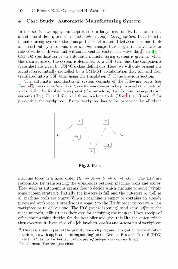
104 C. Fischer, E.-R. Olderog, and H. Wehrheim
4 Case Study: Automatic Manufacturing System
In this section we apply our approach to a larger case study. It concerns thearchitectural description of an automatic manufacturing system. In automaticmanufacturing systems the transportation of material between machine toolsis carried out by autonomous or holonic transportation agents, i.e. vehicles orrobots without drivers and without a central control for scheduling2. In [19] aCSP-OZ specification of an automatic manufacturing system is given in whichthe architecture of the system is described by a CSP term and the components(capsules) are given by CSP-OZ class definitions. Here, we will only present thearchitecture, initially modelled by a UML-RT collaboration diagram and thentranslated into a CSP term using the translation T of the previous section.
The automatic manufacturing system consists of the following parts (seeFigure 3): two stores In and Out , one for workpieces to be processed (the in-store)and one for the finished workpieces (the out-store); two holonic transportationsystems (Hts) T1 and T2; and three machine tools (Wzm3) A, B and C forprocessing the workpieces. Every workpiece has to be processed by all three
B
CA
T1
T2
In Out
Fig. 3. Plant
machine tools in a fixed order (In → A → B → C → Out). The Hts’ areresponsible for transporting the workpieces between machine tools and stores.They work as autonomous agents, free to decide which machine to serve (withinsome chosen strategy). Initially the in-store is full and the out-store as well asall machine tools are empty. When a machine is empty or contains an alreadyprocessed workpiece it broadcasts a request to the Hts in order to receive a newworkpiece or to deliver one. The Hts’ (when listening) send some offer to themachine tools, telling them their cost for satisfying the request. Upon receipt ofoffers the machine decides for the best offer and give this Hts the order, whichthen executes it. Execution of a job involves loading and deloading of workpieces2 This case study is part of the priority research program “Integration of specification
techniques with applications in engineering” of the German Research Council (DFG)(http://tfs.cs.tu-berlin.de/projekte/indspec/SPP/index.html).
3 in German: Werkzeugmaschine
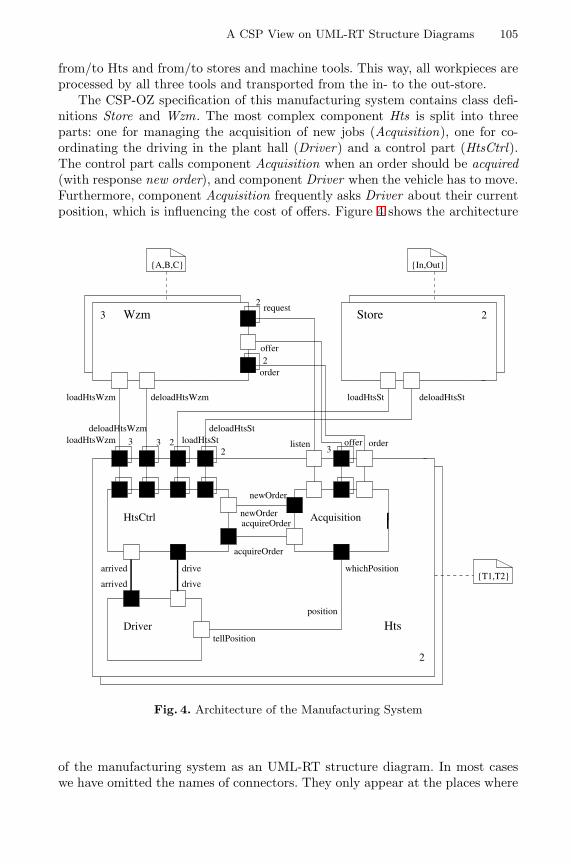
A CSP View on UML-RT Structure Diagrams 105
from/to Hts and from/to stores and machine tools. This way, all workpieces areprocessed by all three tools and transported from the in- to the out-store.
The CSP-OZ specification of this manufacturing system contains class defi-nitions Store and Wzm. The most complex component Hts is split into threeparts: one for managing the acquisition of new jobs (Acquisition), one for co-ordinating the driving in the plant hall (Driver) and a control part (HtsCtrl).The control part calls component Acquisition when an order should be acquired(with response new order), and component Driver when the vehicle has to move.Furthermore, component Acquisition frequently asks Driver about their currentposition, which is influencing the cost of offers. Figure 4 shows the architecture
drive
drivearrived
arrived
2
order
offer
tellPosition
whichPosition
listen offer order
2
request3 Wzm Store
Hts
HtsCtrl
Driver
Acquisition
position
loadHtsSt deloadHtsSt
loadHtsWzm
loadHtsWzm deloadHtsWzm
acquireOrder
acquireOrder
newOrder
newOrder
deloadHtsWzmloadHtsSt
deloadHtsSt
3 32
23
2
2
{T1,T2}
{A,B,C} {In,Out}
Fig. 4. Architecture of the Manufacturing System
of the manufacturing system as an UML-RT structure diagram. In most caseswe have omitted the names of connectors. They only appear at the places where
106 C. Fischer, E.-R. Olderog, and H. Wehrheim
they are necessary in the transformation: when the connected ports have diffe-rent names. In the other cases, we simply assume that the connector name equalsthe names of connected ports (and consequently omit the otherwise necessaryrenaming). We also sometimes omit port names of subcapsules when they agreewith the port names of the compound capsule. The set of process equations cor-responding to the graphical architecture description is constructed inductively.First, the process names and parameters for all basic capsules are fixed. Foreach of these names, a corresponding CSP-OZ class has to be declared in therest of the specification. Thus we for instance get classes Acquisition(Adroffer )and HtsCtrl(AdrloadHtsWzm ,AdrdeloadHtsWzm ,AdrloadHtsSt ,AdrdeloadHtsSt).
Next, we construct the process equations for the multi-capsules Store andWzm. Their process names are MStore and MWzm, respectively. Due to lack ofspace we omit them here and focus on the most complex component Hts.
First, the process equation for the compound capsule is constructed.
Hts(AdrloadHtsWzm ,AdrdeloadHtsWzm ,AdrloadHtsSt ,AdrdeloadHtsSt ,Adroffer ) =
(Driver [tellPosition 7→ position] ADriver ||AAcqui∪ACtrl
(Acquisition(Adroffer )[whichPosition 7→ position] AAcqui ||ACtrl
HtsCtrl(AdrloadHtsWzm ,AdrdeloadHtsWzm ,AdrloadHtsSt ,AdrdeloadHtsSt)))\HHts
For reasons of readability we have unfolded the iterated alphabetised parallelcomposition in the process equation for Hts. The sets A... contain all names ofconnectors attached to the capsule (in this case equal to the corresponding portnames), HHts = {arrived , drive, position, acquireOrder ,newOrder}. The rena-ming PHts is in this case empty since we have adopted the convention thatomitted connector names equal their port names.Next, the process equation for the multi-capsule MHts is constructed:
MHts(AdrloadHtsWzm ,AdrdeloadHtsWzm ,AdrloadHtsSt ,AdrdeloadHtsSt ,Adroffer ) =
‖|in:{T1,T2} • Hts(AdrloadHtsWzm ,AdrdeloadHtsWzm ,
AdrloadHtsSt ,AdrdeloadHtsSt ,Adroffer )[(in)]
Finally we can give the system description, applying once again the translationscheme for compound capsules:
System =
(MHts({A,B ,C}, {A,B ,C}, {In,Out}, {In,Out}, {A,B ,C})AMHts ||AMWzm∪AMStore
(MWzm({T1,T2}, {T1,T2}) AMWzm ||AMStore MStore)) \ HSystem
This completes the translation.
A CSP View on UML-RT Structure Diagrams 107
5 Conclusion
In this paper, we have proposed a translation of UML-RT structure diagramsinto CSP. This allows us to use graphical architecture descriptions in CSP-OZwithout losing its formal semantics. The technique is not only applicable to CSP-OZ specifications, but more generally to all specification languages which useCSP for structure descriptions. The only change needed then is the interpretationof basic capsules, which stand for CSP-OZ classes in our case but may also beinterpreted differently. The translation gives one possible semantics to UML-RTcollaboration diagrams. In a different setting (for instance hardware design on amuch lower abstraction level), a different semantics might be conceivable.
The basis for the translation given in this paper is a formalisation of thesyntax of UML-RT structure diagrams in Object-Z. This is similar to the workdone in [10], which formalises the syntax of UML class diagrams with Z and usesthe formalisation for a translation of class diagrams to Object-Z classes.
So far we have not explicitly treated protocols, which are also part of UML-RT. Protocols are used for specifying the type of interactions which may takeplace over some connector. A protocol can for instance define a set of signalspassed over a connector, or can give a valid communication sequence. Sincethe basic communication paradigm of CSP is synchronous communication, wehave assumed that all protocols define synchronous communication over a singlechannel. However, we envisage the possibility of using more elaborate protocolsin an architecture description, for instance protocols for defining asynchronouscommunication or communication over unreliable channels. To fit into the CSPview on UML-RT diagrams, these protocols should be specified in CSP. Thisapproach to protocol definition is similar to the method chosen in WRIGHT[1], an architecture description language (ADL) based on CSP. In WRIGHT, anarchitecture description consists of a set of components together with a collectionof connectors which are given in CSP.
Another work similar to ours is the ADL Darwin [11]. Darwin is both agraphical and a textual modelling language; it has a formal semantics in termsof Milner’s π-calculus [12]. The usage of a calculus with mobility is necessarythere because Darwin allows to specify dynamically evolving system structures.Since our goal was to find a graphical description of CSP structure specifications,we had no need for incorporating facilities for describing mobility.
A completely different semantic approach to UML-RT diagrams can be fo-und in [8]. There the focus is on using a visual but still well-defined formalism(interaction graphs) for interpreting UML-RT diagrams.
References
1. R. Allen and D. Garlan. A formal basis for architectural connection. ACM Tran-sactions on Software Engineering and Methodology, 1997.
2. G. Booch, J. Rumbaugh, and I. Jacobson. The Unified Modeling Language userguide. Addison Wesley, 1999.
108 C. Fischer, E.-R. Olderog, and H. Wehrheim
3. T. Clark and A. Evans. Foundations of the unified modeling language. In NorthernFormal Methods Workshop, Electronic Workshops in Computing. Springer, 1998.
4. S. Dupuy, Y. Ledru, and M. Chabre-Peccoud. Translating the OMT dynamicmodel into Object-Z. In J.P. Bowen, A. Fett, and M.G. Hinchey, editors, ZUM’98:The Z Formal Specification Notation, volume 1493 of Lecture Notes in ComputerScience, pages 347–366. Springer, 1998.
5. C. Fischer. CSP-OZ: A combination of Object-Z and CSP. In H. Bowman andJ. Derrick, editors, Formal Methods for Open Object-Based Distributed Systems(FMOODS ’97), volume 2, pages 423–438. Chapman & Hall, 1997.
6. C. Fischer. Combination and Implementation of Processes and Data: From CSP-OZ to Java. PhD thesis, Bericht Nr. 2/2000, University of Oldenburg, April 2000.
7. R. France and B. Rumpe, editors. UML’99: The Modified Modeling Language –Beyond the Standard, volume 1723 of Lecture Notes in Computer Science. Springer,1999.
8. R. Grosu, M. Broy, B. Selic, and G. Stefanescu. What is behind UML-RT? InBehavioural Specifications of business and systems. Kluwer, 1999.
9. C. A. R. Hoare. Communicating Sequential Processes. Prentice Hall, 1985.10. S.-K. Kim and D. Carrington. Formalizing the UML class diagram using Object-Z.
In R. France and B. Rumpe, editors, UML’99: The Unified Modelling Language –Beyond the Standard, volume 1723 of Lecture Notes in Computer Science, pages83–98. Springer, 1999.
11. J. Magee, N. Dulay, S. Eisenbach, and J. Kramer. Specifying distributed softwarearchitectures. In ESEC ’95: European Software Engineering Conference, 1995.
12. R. Milner. Communicating and Mobile Systems: The π-Calculus. Cambridge Uni-versity Press, 1999.
13. Object Management Group. OMG Unified Modeling Language Specification, June1999. version 1.3.
14. E.-R. Olderog and A.P. Ravn. Documenting design refinement. In M.P.E. Heim-dahl, editor, Proc. of the Third Workshop on Formal Methods in Software Practice,pages 89–100. ACM, 2000.
15. A. W. Roscoe. The Theory and Practice of Concurrency. Prentice-Hall, 1997.16. B. Selic and J. Rumbaugh. Using UML for modeling complex real-time systems.
Technical report, ObjecTime, 1998.17. G. Smith. The Object-Z Specification Language. Kluwer Academic Publisher, 2000.18. J. M. Spivey. The Z Notation: A Reference Manual. Prentice-Hall International
Series in Computer Science, 2nd edition, 1992.19. H. Wehrheim. Specification of an automatic manufacturing system – a case study in
using integrated formal methods. In T. Maibaum, editor, FASE 2000: FundamentalAspects of Software Engineering, number 1783 in LNCS. Springer, 2000.
Strengthening UML Collaboration Diagrams byState Transformations?
Reiko Heckel and Stefan Sauer
University of Paderborn, Dept. of Mathematics and Computer ScienceD-33095 Paderborn, Germany
reiko|[email protected]
Abstract. Collaboration diagrams as described in the official UMLdocuments specify patterns of system structure and interaction.In this paper, we propose their use for specifying, in addition,pre/postconditions and state transformations of operations and scenar-ios. This conceptual idea is formalized by means of graph transformationsystems and graph process, thereby integrating the state transformationwith the structural and the interaction aspect.
Keywords: UML collaboration diagrams, pre/postconditions, graphtransformation, graph process
1 Introduction
The Unified Modeling Language (UML) [24] provides a collection of loosely cou-pled diagram languages for specifying models of software systems on all levels ofabstraction, ranging from high-level requirement specifications over analysis anddesign models to visual programs. On each level, several kinds of diagrams areavailable to specify different aspects of the system, like the structural, functional,or interaction aspect. But even diagrams of the same kind may have differentinterpretations when used on different levels, while several aspects of the samelevel may be expressed within a single diagram.
For example, interaction diagrams in UML, like sequence or collaborationdiagrams, often represent sample communication scenarios, e.g., as refinementof a use case, or they may be used in order to give a complete specification ofthe protocol which governs the communication. Collaboration diagrams allow,in addition, to represent individual snapshots of the system as well as structuralpatterns.
If such multi-purpose diagrammatic notations shall be employed success-fully, a precise understanding of their different aspects and abstraction levelsis required, as well as a careful analysis of their mutual relations. This under-standing, once suitably formalized, can be the basis for tool support of processmodels, e.g., in the form of consistency checks or refinement rules.? Research partially supported by the ESPRIT Working Group APPLIGRAPH.
H. Hussmann (Ed.): FASE 2001, LNCS 2029, pp. 109–123, 2001.c© Springer-Verlag Berlin Heidelberg 2001
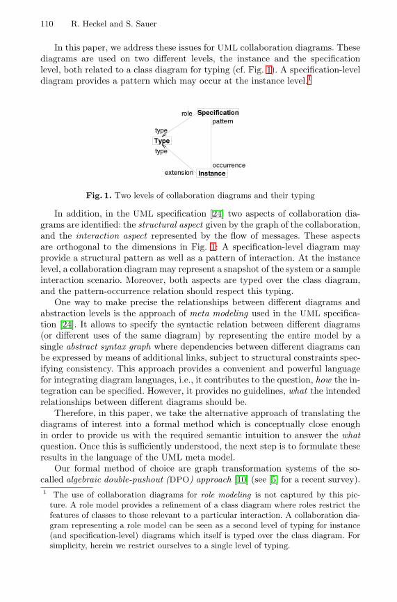
110 R. Heckel and S. Sauer
In this paper, we address these issues for UML collaboration diagrams. Thesediagrams are used on two different levels, the instance and the specificationlevel, both related to a class diagram for typing (cf. Fig. 1). A specification-leveldiagram provides a pattern which may occur at the instance level.1
Specification
Instance
Type
type
type
occurrenceextension
patternrole
Fig. 1. Two levels of collaboration diagrams and their typing
In addition, in the UML specification [24] two aspects of collaboration dia-grams are identified: the structural aspect given by the graph of the collaboration,and the interaction aspect represented by the flow of messages. These aspectsare orthogonal to the dimensions in Fig. 1: A specification-level diagram mayprovide a structural pattern as well as a pattern of interaction. At the instancelevel, a collaboration diagram may represent a snapshot of the system or a sampleinteraction scenario. Moreover, both aspects are typed over the class diagram,and the pattern-occurrence relation should respect this typing.
One way to make precise the relationships between different diagrams andabstraction levels is the approach of meta modeling used in the UML specifica-tion [24]. It allows to specify the syntactic relation between different diagrams(or different uses of the same diagram) by representing the entire model by asingle abstract syntax graph where dependencies between different diagrams canbe expressed by means of additional links, subject to structural constraints spec-ifying consistency. This approach provides a convenient and powerful languagefor integrating diagram languages, i.e., it contributes to the question, how the in-tegration can be specified. However, it provides no guidelines, what the intendedrelationships between different diagrams should be.
Therefore, in this paper, we take the alternative approach of translating thediagrams of interest into a formal method which is conceptually close enoughin order to provide us with the required semantic intuition to answer the whatquestion. Once this is sufficiently understood, the next step is to formulate theseresults in the language of the UML meta model.
Our formal method of choice are graph transformation systems of the so-called algebraic double-pushout (DPO) approach [10] (see [5] for a recent survey).1 The use of collaboration diagrams for role modeling is not captured by this pic-
ture. A role model provides a refinement of a class diagram where roles restrict thefeatures of classes to those relevant to a particular interaction. A collaboration dia-gram representing a role model can be seen as a second level of typing for instance(and specification-level) diagrams which itself is typed over the class diagram. Forsimplicity, herein we restrict ourselves to a single level of typing.
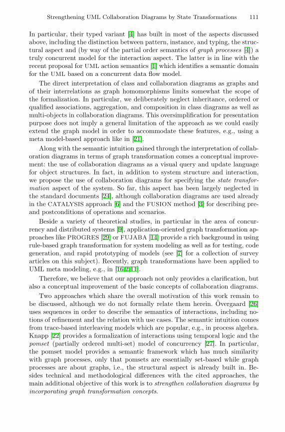
Strengthening UML Collaboration Diagrams by State Transformations 111
In particular, their typed variant [4] has built in most of the aspects discussedabove, including the distinction between pattern, instance, and typing, the struc-tural aspect and (by way of the partial order semantics of graph processes [4]) atruly concurrent model for the interaction aspect. The latter is in line with therecent proposal for UML action semantics [1] which identifies a semantic domainfor the UML based on a concurrent data flow model.
The direct interpretation of class and collaboration diagrams as graphs andof their interrelations as graph homomorphisms limits somewhat the scope ofthe formalization. In particular, we deliberately neglect inheritance, ordered orqualified associations, aggregation, and composition in class diagrams as well asmulti-objects in collaboration diagrams. This oversimplification for presentationpurpose does not imply a general limitation of the approach as we could easilyextend the graph model in order to accommodate these features, e.g., using ameta model-based approach like in [21].
Along with the semantic intuition gained through the interpretation of collab-oration diagrams in terms of graph transformation comes a conceptual improve-ment: the use of collaboration diagrams as a visual query and update languagefor object structures. In fact, in addition to system structure and interaction,we propose the use of collaboration diagrams for specifying the state transfor-mation aspect of the system. So far, this aspect has been largely neglected inthe standard documents [24], although collaboration diagrams are used alreadyin the CATALYSIS approach [6] and the FUSION method [3] for describing pre-and postconditions of operations and scenarios.
Beside a variety of theoretical studies, in particular in the area of concur-rency and distributed systems [9], application-oriented graph transformation ap-proaches like PROGRES [29] or FUJABA [14] provide a rich background in usingrule-based graph transformation for system modeling as well as for testing, codegeneration, and rapid prototyping of models (see [7] for a collection of surveyarticles on this subject). Recently, graph transformations have been applied toUML meta modeling, e.g., in [16,2,11].
Therefore, we believe that our approach not only provides a clarification, butalso a conceptual improvement of the basic concepts of collaboration diagrams.
Two approaches which share the overall motivation of this work remain tobe discussed, although we do not formally relate them herein. Overgaard [26]uses sequences in order to describe the semantics of interactions, including no-tions of refinement and the relation with use cases. The semantic intuition comesfrom trace-based interleaving models which are popular, e.g., in process algebra.Knapp [22] provides a formalization of interactions using temporal logic and thepomset (partially ordered multi-set) model of concurrency [27]. In particular,the pomset model provides a semantic framework which has much similaritywith graph processes, only that pomsets are essentially set-based while graphprocesses are about graphs, i.e., the structural aspect is already built in. Be-sides technical and methodological differences with the cited approaches, themain additional objective of this work is to strengthen collaboration diagrams byincorporating graph transformation concepts.
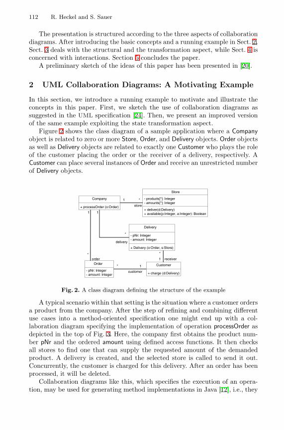
112 R. Heckel and S. Sauer
The presentation is structured according to the three aspects of collaborationdiagrams. After introducing the basic concepts and a running example in Sect. 2,Sect. 3 deals with the structural and the transformation aspect, while Sect. 4 isconcerned with interactions. Section 5 concludes the paper.
A preliminary sketch of the ideas of this paper has been presented in [20].
2 UML Collaboration Diagrams: A Motivating Example
In this section, we introduce a running example to motivate and illustrate theconcepts in this paper. First, we sketch the use of collaboration diagrams assuggested in the UML specification [24]. Then, we present an improved versionof the same example exploiting the state transformation aspect.
Figure 2 shows the class diagram of a sample application where a Companyobject is related to zero or more Store, Order, and Delivery objects. Order objectsas well as Delivery objects are related to exactly one Customer who plays the roleof the customer placing the order or the receiver of a delivery, respectively. ACustomer can place several instances of Order and receive an unrestricted numberof Delivery objects.
Company
+ processOrder (o:Order)
Store
- products[*]: Integer- amounts[*]: Integer
+ deliver(d:Delivery)+ available(p:Integer, a:Integer): Boolean
1 *
store
Delivery
- pNr: Integer- amount: Integer
+ Delivery (o:Order, s:Store)
1
*
delivery
Order
- pNr: Integer- amount: Integer
1
*
Customer
+ charge (d:Delivery)
* 1
*
1
customer
order receiver
Fig. 2. A class diagram defining the structure of the example
A typical scenario within that setting is the situation where a customer ordersa product from the company. After the step of refining and combining differentuse cases into a method-oriented specification one might end up with a col-laboration diagram specifying the implementation of operation processOrder asdepicted in the top of Fig. 3. Here, the company first obtains the product num-ber pNr and the ordered amount using defined access functions. It then checksall stores to find one that can supply the requested amount of the demandedproduct. A delivery is created, and the selected store is called to send it out.Concurrently, the customer is charged for this delivery. After an order has beenprocessed, it will be deleted.
Collaboration diagrams like this, which specifies the execution of an opera-tion, may be used for generating method implementations in Java [12], i.e., they
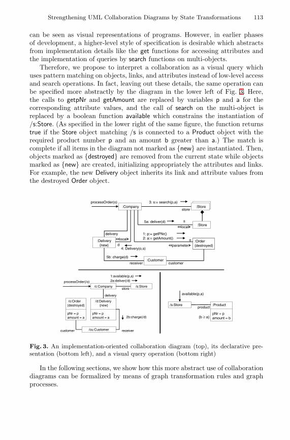
Strengthening UML Collaboration Diagrams by State Transformations 113
can be seen as visual representations of programs. However, in earlier phasesof development, a higher-level style of specification is desirable which abstractsfrom implementation details like the get functions for accessing attributes andthe implementation of queries by search functions on multi-objects.
Therefore, we propose to interpret a collaboration as a visual query whichuses pattern matching on objects, links, and attributes instead of low-level accessand search operations. In fact, leaving out these details, the same operation canbe specified more abstractly by the diagram in the lower left of Fig. 3. Here,the calls to getpNr and getAmount are replaced by variables p and a for thecorresponding attribute values, and the call of search on the multi-object isreplaced by a boolean function available which constrains the instantiation of/s:Store. (As specified in the lower right of the same figure, the function returnstrue if the Store object matching /s is connected to a Product object with therequired product number p and an amount b greater than a.) The match iscomplete if all items in the diagram not marked as {new} are instantiated. Then,objects marked as {destroyed} are removed from the current state while objectsmarked as {new} are created, initializing appropriately the attributes and links.For example, the new Delivery object inherits its link and attribute values fromthe destroyed Order object.
:CompanyprocessOrder(o) 3: s:= search(p,a)
:Store
:Stores
ÿÿlocal ��5a: deliver(d)
1: p:= getPNr()2: a:= getAmount()
:Order{destroyed}ÿÿparameter ��
o
store
deliveryÿÿlocal ��:Delivery
{new}4: Delivery(o,s)
d
:Customer5b: charge(d)
receiver customer
/c:Company /s:Store
/d:Delivery{new}
pNr = pamount = a
/o:Order{destroyed}
pNr = pamount = a
store
delivery
processOrder(/o)
1:available(p,a)2a:deliver(/d)
customer /cu:Customer receiver
2b:charge(/d)
/s:Store :Product
pNr = pamount = b
product
available(p,a)
{b ‡ a}
Fig. 3. An implementation-oriented collaboration diagram (top), its declarative pre-sentation (bottom left), and a visual query operation (bottom right)
In the following sections, we show how this more abstract use of collaborationdiagrams can be formalized by means of graph transformation rules and graphprocesses.
114 R. Heckel and S. Sauer
3 Collaborations as Graph Transformations
A collaboration on specification level is a graph of classifier roles and associationroles which specifies a view of the classes and associations of a class diagramas well as a pattern for objects and links on the instance level. This triangularrelationship, which instantiates the type-specification-instance pattern of Fig. 1for the structural aspect, shall be formalized in the first part of this section.Then, the state transformation aspect shall be described by means of graphtransformations. The interaction aspect is considered in the next section.
Structure. Focusing on the structural aspect first, we use graphs and graph ho-momorphisms (i.e., structure-compatible mappings between graphs) to describethe interrelations between class diagrams and collaboration diagrams on thespecification and the instance level.
The relation between class and instance diagrams is formally captured by theconcept of type and instance graphs [4]. By graphs we mean directed unlabeledgraphs G = 〈GV , GE , srcG, tarG〉 with set of vertices GV , set of edges GE , andfunctions srcG : GE → GV and tarG : GE → GV associating to each edge itssource and target vertex, respectively. A graph homomorphism f : G → H is apair of functions 〈fV : GV → HV , fE : GE → HE〉 compatible with source andtarget, i.e., for all edges e in GE , fV (srcG(e)) = srcH(fE(e)) and fV (tarG(e)) =tarH(fE(e)).
Let TG be the underlying graph of a class diagram, called type graph. Alegal instance graph over TG consists of a graph G together with a typing ho-momorphism g : G → TG associating to each vertex and edge x of G its typeg(x) = t in TG. In UML notation, we write x : t. Observe that the compatibilityof g with source and target ensures that, e.g., the class of the source object ofa link is the source class of the link’s association. Constraints like this can befound in the meta class diagrams and well-formedness rules of the UML metamodel for the meta associations relating classifiers with instances, associationswith links, association ends with link ends, etc. ([24], Sect. 2.9). The typing ofspecification-level graphs is described in a similar way ([24], Sect. 2.10).
An interpretation of a graph homomorphism which is conceptually different,but requires the same notion of structural compatibility, is the occurrence of apattern in a graph. For example, a collaboration on the specification level occursin a collaboration on the instance level if there exists a mapping from classifierroles to instances and from association roles to links preserving the connections.Thus, the existence of a graph homomorphism from a given pattern graph impliesthe presence of a corresponding instance level structure. The occurrence has tobe type-compatible, i.e., if a classifier role is mapped to an instance, both have tobe of the same classifier. This compatibility is captured in the notion of a typedgraph homomorphism between typed graphs, i.e., a graph homomorphism whichpreserves the typing. In our collaboration diagrams, this concept of graphicalpattern matching is used to express visual queries on object structures.
In summary, class and collaboration diagrams have a homogeneous, graph-like structure, and their triangular relationship can be expressed by three com-patible graph homomorphisms. Next, this triangular relation shall be lifted tothe state transformation view.
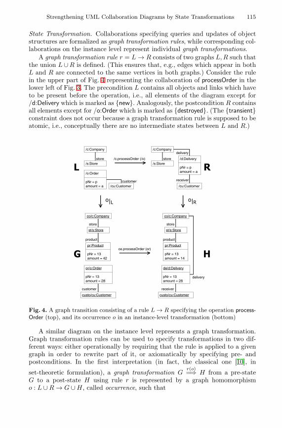
Strengthening UML Collaboration Diagrams by State Transformations 115
State Transformation. Collaborations specifying queries and updates of objectstructures are formalized as graph transformation rules, while corresponding col-laborations on the instance level represent individual graph transformations.
A graph transformation rule r = L → R consists of two graphs L, R such thatthe union L ∪ R is defined. (This ensures that, e.g., edges which appear in bothL and R are connected to the same vertices in both graphs.) Consider the rulein the upper part of Fig. 4 representing the collaboration of processOrder in thelower left of Fig. 3. The precondition L contains all objects and links which haveto be present before the operation, i.e., all elements of the diagram except for/d:Delivery which is marked as {new}. Analogously, the postcondition R containsall elements except for /o:Order which is marked as {destroyed}. (The {transient}constraint does not occur because a graph transformation rule is supposed to beatomic, i.e., conceptually there are no intermediate states between L and R.)
/c:Company
/s:Store/d:Delivery
pNr = pamount = a/o:Order
pNr = pamount = a
store
delivery
/c.processOrder (/o)
/c:Company
/s:Storestore
/cu:Customercustomer receiver
/cu:Customer
/ 5
R_/ R_5
ce.processOrder (or)
co/c:Company
st/s:Store
or/o:Order
pNr = 13amount = 28
store
customer
custo/cu:Customer
pr:Product
pNr = 13amount = 42
product
co/c:Company
st/s:Store
de/d:Delivery
pNr = 13amount = 28
store
receiver
custo/cu:Customer
pr:Product
pNr = 13amount = 14
product
delivery
* +
Fig. 4. A graph transition consisting of a rule L → R specifying the operation process-Order (top), and its occurrence o in an instance-level transformation (bottom)
A similar diagram on the instance level represents a graph transformation.Graph transformation rules can be used to specify transformations in two dif-ferent ways: either operationally by requiring that the rule is applied to a givengraph in order to rewrite part of it, or axiomatically by specifying pre- andpostconditions. In the first interpretation (in fact, the classical one [10], in
set-theoretic formulation), a graph transformation Gr(o)=⇒ H from a pre-state
G to a post-state H using rule r is represented by a graph homomorphismo : L ∪ R → G ∪ H, called occurrence, such that
116 R. Heckel and S. Sauer
1. o(L) ⊆ G and o(R) ⊆ H (i.e., the left-hand side of the rule is matched bythe pre-state and the right-hand side by the post-state),
2. o(L \R) = G \H and o(R \L) = H \G (i.e., all objects of G are {destroyed}that match classifier roles of L not belonging to R and, symmetrically, allobjects of H are {new} that match classifier roles in R not belonging to L).
That is, the transformation creates and destroys exactly what is specified by therule and the occurrence. As a consequence, the rule together with the occurrenceof the left-hand side L in the given graph G determines, up to renaming, thederived graph H, i.e., the approach has a clear operational interpretation, whichis well-suited for visual programming.
In the more liberal, axiomatic interpretation, requirement 2 is weakened to
2′. o(L \ R) ⊆ G \ H and o(R \ L) ⊆ H \ G (i.e., at least the objects of Gare {destroyed} that match classifier roles of L not belonging to R and,symmetrically, at least the objects of H are {new} that match classifier rolesin R not belonging to L).
These so-called graph transitions [19] allow side effects not specified by the rule,like in the example of Fig. 4 where the amount of product pr changes withoutbeing explicitly rewritten by the rule. This is important for high-level modelingwhere specifications of behavior are often incomplete.
In both cases, instance transformations as well as specification-level rules aretyped over the same type graph, and the occurrence homomorphism respectsthese types. This completes the instantiation of the type-specification-instancepattern for the aspect of state transformation.
Summarizing, a collaboration on the specification level represents a patternfor state transformations on the instance level, and the occurrence of this patternrequires, beside the structural match of the pre- and postconditions, (at least)the realization of the described effects. Graph transformations provide a formalmodel for the state transformation aspect which allows to describe the overalleffect of a complex interaction. However, the interaction itself, which decomposesthe global steps into more basic actions, is not modeled. In the next section, thisfiner structure shall be described in terms of the model of concurrency for graphtransformation systems [4].
4 Interactions as Graph Processes
In this section, we shall extend the triangular type-specification-instance patternto the interaction part. First, we describe the formalization of the individualconcepts and then the typing and occurrence relations.
Class diagrams. A class diagram is represented as a graph transformation sys-tem, briefly GTS, G = 〈TG, R〉 consisting of a type graph TG and a set oftransformation rules R. The type graph captures the structural aspect of theclass diagram, like the classes, associations, and attributes, as well as the typesof call and return messages that are sent when an operation is invoked. For the
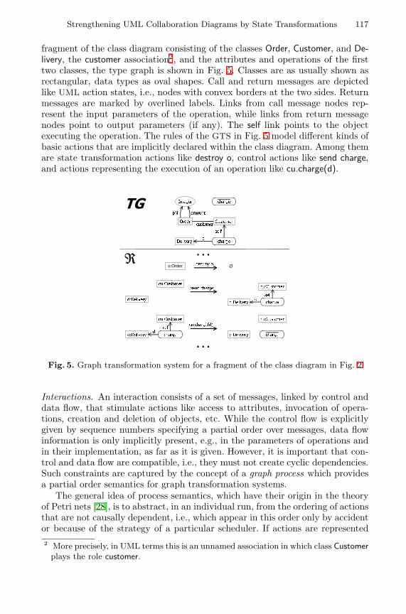
Strengthening UML Collaboration Diagrams by State Transformations 117
fragment of the class diagram consisting of the classes Order, Customer, and De-livery, the customer association2, and the attributes and operations of the firsttwo classes, the type graph is shown in Fig. 5. Classes are as usually shown asrectangular, data types as oval shapes. Call and return messages are depictedlike UML action states, i.e., nodes with convex borders at the two sides. Returnmessages are marked by overlined labels. Links from call message nodes rep-resent the input parameters of the operation, while links from return messagenodes point to output parameters (if any). The self link points to the objectexecuting the operation. The rules of the GTS in Fig. 5 model different kinds ofbasic actions that are implicitly declared within the class diagram. Among themare state transformation actions like destroy o, control actions like send charge,and actions representing the execution of an operation like cu.charge(d).
7*
´
2UGHU &XVWRPHU
,QWHJHU FKDUJH
'HOLYHU\
S1U DPRXQW
VHOI
GFKDUJH
o:Order ˘GHVWUR\ R
�����
VHQG FKDUJH
FX�FKDUJH�G�
�����
FX�&XVWRPHU
G�'HOLYHU\
VHOIG
FKDUJH
FX�&XVWRPHU
G�'HOLYHU\
FX�&XVWRPHU
G�'HOLYHU\
VHOIG
FKDUJH
FX�&XVWRPHU
G�'HOLYHU\ FKDUJH
FXVWRPHU
Fig. 5. Graph transformation system for a fragment of the class diagram in Fig. 2
Interactions. An interaction consists of a set of messages, linked by control anddata flow, that stimulate actions like access to attributes, invocation of opera-tions, creation and deletion of objects, etc. While the control flow is explicitlygiven by sequence numbers specifying a partial order over messages, data flowinformation is only implicitly present, e.g., in the parameters of operations andin their implementation, as far as it is given. However, it is important that con-trol and data flow are compatible, i.e., they must not create cyclic dependencies.Such constraints are captured by the concept of a graph process which providesa partial order semantics for graph transformation systems.
The general idea of process semantics, which have their origin in the theoryof Petri nets [28], is to abstract, in an individual run, from the ordering of actionsthat are not causally dependent, i.e., which appear in this order only by accidentor because of the strategy of a particular scheduler. If actions are represented2 More precisely, in UML terms this is an unnamed association in which class Customer
plays the role customer.
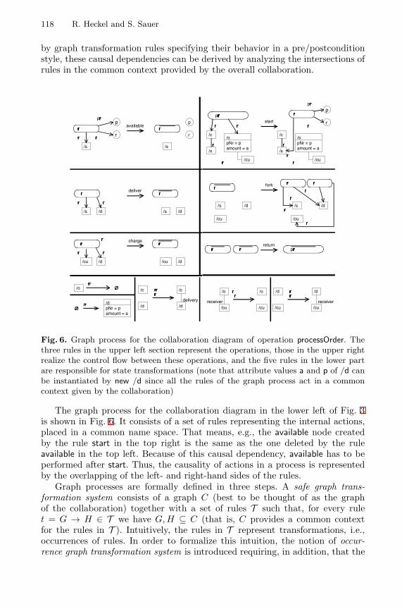
118 R. Heckel and S. Sauer
by graph transformation rules specifying their behavior in a pre/postconditionstyle, these causal dependencies can be derived by analyzing the intersections ofrules in the common context provided by the overall collaboration.
ÿ
�
/s
available
�� ��
ÿ������
� ��� ��
ÿ
�
/s
/s
deliver
�� ��
/d
� � � � � �� �
/s /d
/cu
charge
�� ��
/d
� � � � � �� �
/cu /d
� �� �� ��� �� �� �� ��� �
� � � � � ��
� �� �� ��� �
�� �� ���
��� ������ � ��
start
ÿ
�
/s
fork
/d
/c
� � � �/s
/opNr = pamount = a
��� �� �
ÿ������
/cu
/s /d
/cu
�� ��
�� ��
�� ���� ��
� � � �� �� �
return
�� �� ��� �/cu
�� ��� �� �/cu
� �� � � � �
�� �� �� �
��� ���
�� �� ��
ÿ���� ��� �� ��
ÿ���� ��� ��� �
� �� �� �� ��
� � �� � �� ��
/c
� �� �
/s
/opNr = pamount = a
�� �� �
�� � �� �� �� �
/o ˘
˘/dpNr = pamount = a
/c
/d
/c
/ddelivery
�� ���� � � �
� �� � �
� �� �� ��� �� �� �� �
/d
/cu
/d
/cureceiver
�� � � �� ���� � � �� ��
/o
/cu
/o
/cureceiver
�� ������ ��� �� �� � � ���
Fig. 6. Graph process for the collaboration diagram of operation processOrder. Thethree rules in the upper left section represent the operations, those in the upper rightrealize the control flow between these operations, and the five rules in the lower partare responsible for state transformations (note that attribute values a and p of /d canbe instantiated by new /d since all the rules of the graph process act in a commoncontext given by the collaboration)
The graph process for the collaboration diagram in the lower left of Fig. 3is shown in Fig. 6. It consists of a set of rules representing the internal actions,placed in a common name space. That means, e.g., the available node createdby the rule start in the top right is the same as the one deleted by the ruleavailable in the top left. Because of this causal dependency, available has to beperformed after start. Thus, the causality of actions in a process is representedby the overlapping of the left- and right-hand sides of the rules.
Graph processes are formally defined in three steps. A safe graph trans-formation system consists of a graph C (best to be thought of as the graphof the collaboration) together with a set of rules T such that, for every rulet = G → H ∈ T we have G, H ⊆ C (that is, C provides a common contextfor the rules in T ). Intuitively, the rules in T represent transformations, i.e.,occurrences of rules. In order to formalize this intuition, the notion of occur-rence graph transformation system is introduced requiring, in addition, that the
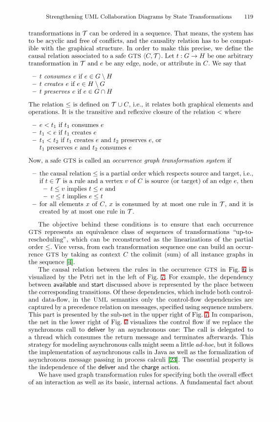
Strengthening UML Collaboration Diagrams by State Transformations 119
transformations in T can be ordered in a sequence. That means, the system hasto be acyclic and free of conflicts, and the causality relation has to be compat-ible with the graphical structure. In order to make this precise, we define thecausal relation associated to a safe GTS 〈C, T 〉. Let t : G → H be one arbitrarytransformation in T and e be any edge, node, or attribute in C. We say that
– t consumes e if e ∈ G \ H– t creates e if e ∈ H \ G– t preserves e if e ∈ G ∩ H
The relation ≤ is defined on T ∪ C, i.e., it relates both graphical elements andoperations. It is the transitive and reflexive closure of the relation < where
– e < t1 if t1 consumes e– t1 < e if t1 creates e– t1 < t2 if t1 creates e and t2 preserves e, or
t1 preserves e and t2 consumes e
Now, a safe GTS is called an occurrence graph transformation system if
– the causal relation ≤ is a partial order which respects source and target, i.e.,if t ∈ T is a rule and a vertex v of C is source (or target) of an edge e, then– t ≤ v implies t ≤ e and– v ≤ t implies e ≤ t
– for all elements x of C, x is consumed by at most one rule in T , and it iscreated by at most one rule in T .
The objective behind these conditions is to ensure that each occurrenceGTS represents an equivalence class of sequences of transformations “up-to-rescheduling”, which can be reconstructed as the linearizations of the partialorder ≤. Vice versa, from each transformation sequence one can build an occur-rence GTS by taking as context C the colimit (sum) of all instance graphs inthe sequence [4].
The causal relation between the rules in the occurrence GTS in Fig. 6 isvisualized by the Petri net in the left of Fig. 7. For example, the dependencybetween available and start discussed above is represented by the place betweenthe corresponding transitions. Of these dependencies, which include both control-and data-flow, in the UML semantics only the control-flow dependencies arecaptured by a precedence relation on messages, specified using sequence numbers.This part is presented by the sub-net in the upper right of Fig. 7. In comparison,the net in the lower right of Fig. 7 visualizes the control flow if we replace thesynchronous call to deliver by an asynchronous one: The call is delegated toa thread which consumes the return message and terminates afterwards. Thisstrategy for modeling asynchronous calls might seem a little ad-hoc, but it followsthe implementation of asynchronous calls in Java as well as the formalization ofasynchronous message passing in process calculi [23]. The essential property isthe independence of the deliver and the charge action.
We have used graph transformation rules for specifying both the overall effectof an interaction as well as its basic, internal actions. A fundamental fact about
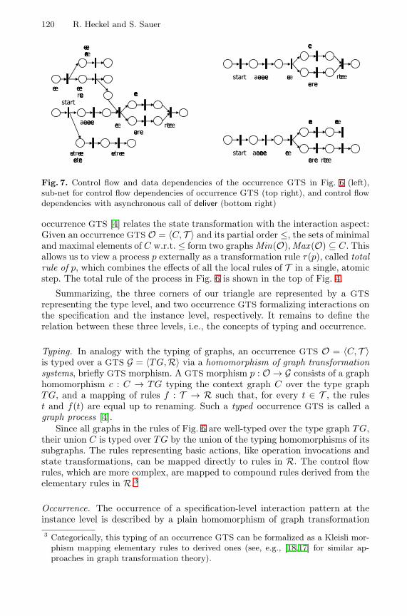
120 R. Heckel and S. Sauer
ÿþýüþ
ý�ý��ý��� � �ü�
� ��� ��ü
��ýü��ü�þ�ü�
��ÿþü�� ��
�� � ��� ��� �� ��ü�
�� � ��� �ü����� �ü
��ÿþü�� �� ��� �ÿþ���ü
��� � �
ÿþýüþ ý�ý��ý��� � �ü�
� ��� ��ü
��ýü��ü�þ�ü�
ÿþýüþ ý�ý��ý��� � �ü�
�� ��� �ü
��ýü�� ü�þ�ü�
� ���ü�
Fig. 7. Control flow and data dependencies of the occurrence GTS in Fig. 6 (left),sub-net for control flow dependencies of occurrence GTS (top right), and control flowdependencies with asynchronous call of deliver (bottom right)
occurrence GTS [4] relates the state transformation with the interaction aspect:Given an occurrence GTS O = 〈C, T 〉 and its partial order ≤, the sets of minimaland maximal elements of C w.r.t. ≤ form two graphs Min(O),Max (O) ⊆ C. Thisallows us to view a process p externally as a transformation rule τ(p), called totalrule of p, which combines the effects of all the local rules of T in a single, atomicstep. The total rule of the process in Fig. 6 is shown in the top of Fig. 4.
Summarizing, the three corners of our triangle are represented by a GTSrepresenting the type level, and two occurrence GTS formalizing interactions onthe specification and the instance level, respectively. It remains to define therelation between these three levels, i.e., the concepts of typing and occurrence.
Typing. In analogy with the typing of graphs, an occurrence GTS O = 〈C, T 〉is typed over a GTS G = 〈TG, R〉 via a homomorphism of graph transformationsystems, briefly GTS morphism. A GTS morphism p : O → G consists of a graphhomomorphism c : C → TG typing the context graph C over the type graphTG, and a mapping of rules f : T → R such that, for every t ∈ T , the rulest and f(t) are equal up to renaming. Such a typed occurrence GTS is called agraph process [4].
Since all graphs in the rules of Fig. 6 are well-typed over the type graph TG,their union C is typed over TG by the union of the typing homomorphisms of itssubgraphs. The rules representing basic actions, like operation invocations andstate transformations, can be mapped directly to rules in R. The control flowrules, which are more complex, are mapped to compound rules derived from theelementary rules in R.3
Occurrence. The occurrence of a specification-level interaction pattern at theinstance level is described by a plain homomorphism of graph transformation3 Categorically, this typing of an occurrence GTS can be formalized as a Kleisli mor-
phism mapping elementary rules to derived ones (see, e.g., [18,17] for similar ap-proaches in graph transformation theory).
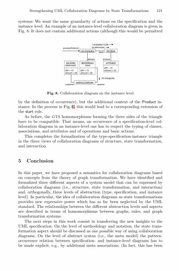
Strengthening UML Collaboration Diagrams by State Transformations 121
systems: We want the same granularity of actions on the specification and theinstance level. An example of an instance-level collaboration diagram is given inFig. 8. It does not contain additional actions (although this would be permitted
co/c:Company st/s:Store
de/d:Delivery {new}
pNr = 13amount = 28
or/o:Order{destroyed}
pNr = 13amount = 28
store
delivery
processOrder(or)
1:available(13,28)2a:deliver(de)
pr:Product
pNr = 13amount = 42
product
customercusto/cu:Customer
receiver
2b:charge(de)
Fig. 8. Collaboration diagram on the instance level
by the definition of occurrence), but the additional context of the Product in-stance. In the process in Fig. 6, this would lead to a corresponding extension ofthe start rule.
As before, the GTS homomorphisms forming the three sides of the trianglehave to be compatible. That means, an occurrence of a specification-level col-laboration diagram in an instance-level one has to respect the typing of classes,associations, and attributes and of operations and basic actions.
This completes the formalization of the type-specification-instance trianglein the three views of collaboration diagrams of structure, state transformation,and interaction.
5 Conclusion
In this paper, we have proposed a semantics for collaboration diagrams basedon concepts from the theory of graph transformation. We have identified andformalized three different aspects of a system model that can be expressed bycollaboration diagrams (i.e., structure, state transformation, and interaction)and, orthogonally, three levels of abstraction (type, specification, and instancelevel). In particular, the idea of collaboration diagrams as state transformationsprovides new expressive power which has so far been neglected by the UMLstandard. The relationships between the different abstraction levels and aspectsare described in terms of homomorphisms between graphs, rules, and graphtransformation systems.
The next steps in this work consist in transferring the new insights to theUML specification. On the level of methodology and notation, the state trans-formation aspect should be discussed as one possible way of using collaborationdiagrams. On the level of abstract syntax (i.e., the meta model) the pattern-occurrence relation between specification- and instance-level diagrams has tobe made explicit, e.g., by additional meta associations. (In fact, this has been
122 R. Heckel and S. Sauer
partly accomplished in the most recent draft of the standard [25].) On the seman-tic level, a representation of the causal dependencies in a collaboration diagramis desirable which captures also the data flow between actions.
It remains to state more precisely the relation between collaboration diagramsas defined by the standard and our extended version. Obviously, although ourcollaboration diagrams are syntactically legal, the collaboration diagrams thatare semantically meaningful according to the UML standard form a strict subsetof our high-level diagrams based on graph matching. An implementation of thismatching by explicit navigation (as it is given, for example, in [14] as part ofa code generation in Java) provides a translation back to the original low-levelstyle. The formal properties of this construction have not been investigate yet.
References
1. Action Semantics Consortium. Precise action semantics for the Unified ModelingLanguage, August 2000. http://www.kc.com/as_site/.
2. P. Bottoni, M. Koch, F. Parisi Presicce, and G. Taentzer. Consistency checkingand visualization of OCL constraints. In Evans et al. [13], pages 294–308.
3. D. Coleman, P. Arnold, S. Bodof, C. Dollin, H. Gilchrist, F. Hayes, and P. Jeremes.Object Oriented Development, The Fusion Method. Prentice Hall, 1994.
4. A. Corradini, U. Montanari, and F. Rossi. Graph processes. Fundamenta Infor-maticae, 26(3,4):241–266, 1996.
5. A. Corradini, U. Montanari, F. Rossi, H. Ehrig, R. Heckel, and M. Lowe. Algebraicapproaches to graph transformation, Part I: Basic concepts and double pushoutapproach. In G. Rozenberg, editor, Handbook of Graph Grammars and Computingby Graph Transformation, Volume 1: Foundations, pages 163–245. World Scientific,1997.
6. D. D’Souza and A. Wills. Components and Frameworks with UML: The CatalysisApproach. Addison-Wesley, 1998.
7. H. Ehrig, G. Engels, H.-J. Kreowski, and G. Rozenberg, editors. Handbook ofGraph Grammars and Computing by Graph Transformation, Volume 2: Applica-tions, Languages, and Tools. World Scientific, 1999.
8. H. Ehrig, G. Engels, H.-J. Kreowski, and G. Rozenberg, editors. Proc. 6thInt. Workshop on Theory and Application of Graph Transformation (TAGT’98),Paderborn, November 1998, volume 1764 of LNCS. Springer-Verlag, 2000.
9. H. Ehrig, H.-J. Kreowski, U. Montanari, and G. Rozenberg, editors. Handbook ofGraph Grammars and Computing by Graph Transformation, Volume 3: Concur-rency and Distribution. World Scientific, 1999.
10. H. Ehrig, M. Pfender, and H.J. Schneider. Graph grammars: an algebraic approach.In 14th Annual IEEE Symposium on Switching and Automata Theory, pages 167–180. IEEE, 1973.
11. G. Engels, J.H. Hausmann, R. Heckel, and St. Sauer. Dynamic meta modeling: Agraphical approach to the operational semantics of behavioral diagrams in UML.In Evans et al. [13], pages 323–337.
12. G. Engels, R. Hucking, St. Sauer, and A. Wagner. UML collaboration diagramsand their transformation to Java. In France and Rumpe [15], pages 473–488.
13. A. Evans, S. Kent, and B. Selic, editors. Proc. UML 2000 – Advancing the Standard,volume 1939 of LNCS. Springer-Verlag, 2000.
Strengthening UML Collaboration Diagrams by State Transformations 123
14. T. Fischer, J. Niere, L. Torunski, and A. Zundorf. Story diagrams: A new graphtransformation language based on UML and Java. In Ehrig et al. [8].
15. R. France and B. Rumpe, editors. Proc. UML’99 – Beyond the Standard, volume1723 of LNCS. Springer-Verlag, 1999.
16. M. Gogolla. Graph transformations on the UML metamodel. In J. D. P. Rolimet al., editors, Proc. ICALP Workshops 2000, Geneva, Switzerland, pages 359–371.Carleton Scientific, 2000.
17. M. Große-Rhode, F. Parisi Presicce, and M. Simeoni. Refinement of graph trans-formation systems via rule expressions. In Ehrig et al. [8], pages 368–382.
18. R. Heckel, A. Corradini, H. Ehrig, and M. Lowe. Horizontal and vertical structuringof typed graph transformation systems. Math. Struc. in Comp. Science, 6(6):613–648, 1996.
19. R. Heckel, H. Ehrig, U. Wolter, and A. Corradini. Double-pullback transitions andcoalgebraic loose semantics for graph transformation systems. Applied CategoricalStructures, 9(1), January 2001.
20. R. Heckel and St. Sauer. Strengthening the semantics of UML collaboration di-agrams. In G. Reggio, A. Knapp, B. Rumpe, B. Selic, and R. Wieringa, editors,UML’2000 Workshop on Dynamic Behavior in UML Models: Semantic Questions,pages 63–69. October 2000. Tech. Report no. 0006, Ludwig-Maximilians-UniversityMunich, Germany.
21. R. Heckel and A. Zundorf. How to specify a graph transformation approach: Ameta model for fujaba. In H. Ehrig and J. Padberg, editors, Uniform Approachesto Graphical Process Specification Techniques, satellite workshop of ETAPS 2001,Genova, Italy, 2001. To appear.
22. A. Knapp. A formal semantics of UML interactions. In France and Rumpe [15],pages 116–130.
23. M. Merro and D. Sangiorgi. On asynchrony in name-passing calculi. In Proc.ICALP’98, volume 1443 of LNCS, pages 856–867. Springer-Verlag, 1998.
24. Object Management Group. UML specification version 1.3, June 1999.http://www.omg.org.
25. Object Management Group. UML specification version 1.4beta R1, November2000. http://www.celigent.com/omg/umlrtf/.
26. G. Overgaard. A formal approach to collaborations in the Unified Modeling Lan-guage. In France and Rumpe [15], pages 99–115.
27. V. Pratt. Modeling concurrency with partial orders. Int. Journal. of ParallelProgramming, 15(1):33–71, February 1986.
28. W. Reisig. Petri Nets, volume 4 of EATCS Monographs on Theoretical ComputerScience. Springer-Verlag, 1985.
29. A. Schurr, A.J. Winter, and A. Zundorf. The PROGRES approach: Language andenvironment. In Ehrig et al. [7], pages 487–550.
Specification of Mixed Systems in Korriganwith the Support of a UML-Inspired Graphical
Notation
Christine Choppy1, Pascal Poizat2, and Jean-Claude Royer2
1 LIPN, Institut Galilee - Universite Paris XIII,Avenue Jean-Baptiste Clement, F-93430 Villetaneuse, France
[email protected] IRIN, Universite de Nantes
2 rue de la Houssiniere, B.P. 92208, F-44322 Nantes cedex 3, France{Pascal.Poizat,Jean-Claude.Royer}@irin.univ-nantes.fr
http://www.sciences.univ-nantes.fr/info/perso/permanents/poizat/
Abstract. Our Korrigan formalism is devoted to the structuredformal specification of mixed systems through a model based on ahierarchy of views [4,20]. In our unifying approach, views are used todescribe the different aspects of a component (both internal and externalstructuring). We propose a semi-formal method with guidelines for thedevelopment of mixed systems, that helps the specifier providing meansto structure the system in terms of communicating subcomponents andto describe the sequential components. While there is growing interestfor having both textual and graphical notations for a given formalism,we introduce composition diagrams, a UML-inspired graphical notationfor Korrigan, associated with the various steps of our method. We shallshow how our method is applied to develop a Korrigan specification(both in textual and graphical notation) and illustrate this approach ona case study.
Keywords: formal specification, mixed specification, graphical notation,symbolic transition systems, Korrigan, UML
1 Introduction
The use of formal specifications is now widely accepted in software developmentto provide abstract, rigorous and complete descriptions of systems. Formal spec-ifications are also essential to prove properties, to prototype the system and togenerate tests.
In the last few years, the need for a separation of concerns with referenceto static (data types) and dynamic aspects (behaviours, communication) ap-peared. This issue was addressed in approaches combining algebraic data typeswith other formalisms (e.g. LOTOS [17] with process algebras or SDL [7] withState/Transition Diagrams), and also more recently in approaches combining Zand process algebras (e.g. OZ-CSP [27] or CSP-OZ [8]). This is also reflected in
H. Hussmann (Ed.): FASE 2001, LNCS 2029, pp. 124–139, 2001.c© Springer-Verlag Berlin Heidelberg 2001
Specification of Mixed Systems in Korrigan 125
object oriented analysis and design approaches such as UML [28] where staticand dynamic aspects are dealt with by different diagrams (class diagrams, in-teraction diagrams, Statecharts). However, the (formal) links and consistencybetween the aspects are not defined, or trivial. This limits either the possibili-ties of reasoning on the whole component or the expressiveness of the formalism.Some approaches encompass both aspects within a single framework (e.g. LTS[24], rewriting logic [19] or TLA [18]). These “homogeneous” approaches easethe verification and the definition of consistency criteria for the integration ofaspects, but at the cost of a loss of expressiveness for one of the aspects or a poorlevel of readability. Moreover, the definition of a method remains an importantlack of most of these approaches.
The Korrigan formalism is devoted to the structured formal specification ofmixed systems through a model based on a hierarchy of views. Our approach aimsat keeping advantage of the languages dedicated to both aspects (i.e. SymbolicTransition Systems for behaviours, algebraic specifications derived from thesediagrams for data parts, and a simple temporal logic and axiom based glue forcompositions) while providing an underlying unifying framework accompaniedby an appropriate semantic model. Moreover, experience has shown that ourformalism leads to expressive and abstract, yet readable specifications.
We propose, in this paper, a semi-formal method with guidelines for the devel-opment of mixed systems with Korrigan. This method helps the specifier pro-viding means to structure the system in terms of communicating subcomponentsand to describe the sequential components. While there is growing interest forhaving both textual and graphical notations for a given formalism (e.g. SDL andUML/XMI), we shall in the following introduce composition diagrams, a UML-inspired graphical notation for Korrigan, associated with the various steps ofour method. We suggest to reuse some UML notation, but we also present someproper Korrigan graphic notations. Since our model is component based wehave an approach which is rather different from UML on communications andconcurrent aspects. Thus we will present specific notations to define the dynamicinterface of a component, its communications with others and concurrency. Weshall show how our method is applied to develop a Korrigan specification (bothin textual and graphical notation) and illustrate this approach on a transit nodecase-study.
The paper is organized as follows. Section 2 presents the Transit Node casestudy. Section 3 gives an overview of Korrigan. It describes briefly the viewmodel and details the associated specification method. Then, in Section 4 wepresent our UML-inspired notation diagrams for interfaces, compositions, be-haviours, and communications. Finally, some related works are discussed in ourconclusion.
2 The Transit Node Case Study
This case study was adapted within the VTT project from one defined in theRACE project 2039 (SPECS: Specification Environment for Communication
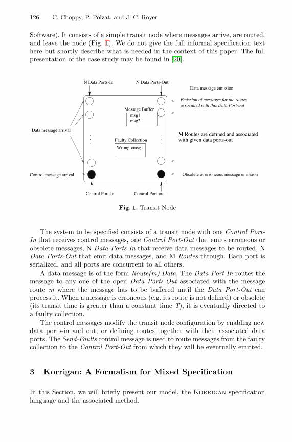
126 C. Choppy, P. Poizat, and J.-C. Royer
Software). It consists of a simple transit node where messages arrive, are routed,and leave the node (Fig. 1). We do not give the full informal specification texthere but shortly describe what is needed in the context of this paper. The fullpresentation of the case study may be found in [20].
.
.
.
.
.
.Faulty Collection
Wrong-cmsg
M Routes are defined and associatedwith given data ports-out
N Data Ports-In N Data Ports-Out
Emission of messages for the routesassociated with this Data Port-out
Message Buffermsg1msg2
Data message emission
Control message arrival Obsolete or erroneous message emission
Control Port-outControl Port-In
Data message arrival
Fig. 1. Transit Node
The system to be specified consists of a transit node with one Control Port-In that receives control messages, one Control Port-Out that emits erroneous orobsolete messages, N Data Ports-In that receive data messages to be routed, NData Ports-Out that emit data messages, and M Routes through. Each port isserialized, and all ports are concurrent to all others.
A data message is of the form Route(m).Data. The Data Port-In routes themessage to any one of the open Data Ports-Out associated with the messageroute m where the message has to be buffered until the Data Port-Out canprocess it. When a message is erroneous (e.g. its route is not defined) or obsolete(its transit time is greater than a constant time T), it is eventually directed toa faulty collection.
The control messages modify the transit node configuration by enabling newdata ports-in and out, or defining routes together with their associated dataports. The Send-Faults control message is used to route messages from the faultycollection to the Control Port-Out from which they will be eventually emitted.
3 Korrigan: A Formalism for Mixed Specification
In this Section, we will briefly present our model, the Korrigan specificationlanguage and the associated method.
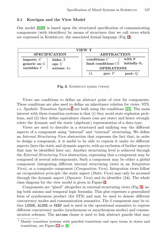
Specification of Mixed Systems in Korrigan 127
3.1 Korrigan and the View Model
Our model [4,20] is based upon the structured specification of communicatingcomponents (with identifiers) by means of structures that we call views whichare expressed in Korrigan, the associated formal language (Fig. 2).
VIEW TSPECIFICATION
imports A′
generic on Gvariables V
hides Aops Σaxioms Ax
ABSTRACTIONconditions Climit conditions Cl
with Φinitially Φ0
OPERATIONS
Oi pre: P post: Q
Fig. 2. Korrigan syntax (views)
Views use conditions to define an abstract point of view for components.These conditions are also used to define an inheritance relation for views. STS,i.e. Symbolic Transition Systems1 are built using the conditions [21]. The maininterest with these transition systems is that (i) they avoid state explosion prob-lems, and (ii) they define equivalence classes (one per state) and hence stronglyrelate the dynamic and the static (algebraic) representation of a data type.
Views are used to describe in a structured and unifying way the differentaspects of a component using “internal” and “external” structuring. We definean Internal Structuring View abstraction that expresses the fact that, in orderto design a component, it is useful to be able to express it under its differentaspects (here the static and dynamic aspects, with no exclusion of further aspectsthat may be identified later on). Another structuring level is achieved throughthe External Structuring View abstraction, expressing that a component may becomposed of several subcomponents. Such a component may be either a globalcomponent (integrating different internal structuring views in an IntegrationView), or a composite component (Composition View). Integration views followan encapsulation principle: the static aspect (Static View) may only be accessedthrough the dynamic aspect (Dynamic View) and its identifier (Id). The wholeclass diagram for the view model is given in Figure 3.
Components are “glued” altogether in external structuring views (Fig. 4) us-ing both axioms and temporal logic formulas. This glue expresses a generalizedform of synchronous product (for STS) and may be used to denote differentconcurrency modes and communication semantics. The δ component may be ei-ther LOOSE, ALONE or KEEP and is used in the operational semantics to expressdifferent concurrency modes (synchronous or asynchronous modes) and commu-nication schemes. The axioms clause is used to link abstract guards that may1 Mainly transition systems with guarded transitions and open terms in states and
transitions, see Figure 12 or [4].
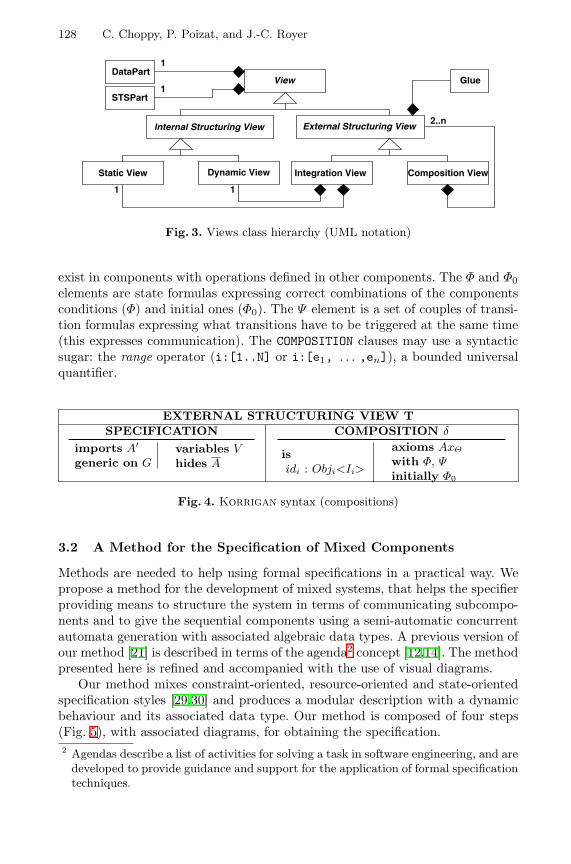
128 C. Choppy, P. Poizat, and J.-C. Royer
Glue
STSPart
Static View Dynamic View
1 1
2..nInternal Structuring View External Structuring View
Composition ViewIntegration View
ViewDataPart
1
1
Fig. 3. Views class hierarchy (UML notation)
exist in components with operations defined in other components. The Φ and Φ0elements are state formulas expressing correct combinations of the componentsconditions (Φ) and initial ones (Φ0). The Ψ element is a set of couples of transi-tion formulas expressing what transitions have to be triggered at the same time(this expresses communication). The COMPOSITION clauses may use a syntacticsugar: the range operator (i:[1..N] or i:[e1, . . . ,en]), a bounded universalquantifier.
EXTERNAL STRUCTURING VIEW TSPECIFICATION
imports A′
generic on Gvariables Vhides A
COMPOSITION δ
isidi : Obji<Ii>
axioms AxΘ
with Φ, Ψinitially Φ0
Fig. 4. Korrigan syntax (compositions)
3.2 A Method for the Specification of Mixed Components
Methods are needed to help using formal specifications in a practical way. Wepropose a method for the development of mixed systems, that helps the specifierproviding means to structure the system in terms of communicating subcompo-nents and to give the sequential components using a semi-automatic concurrentautomata generation with associated algebraic data types. A previous version ofour method [21] is described in terms of the agenda2 concept [12,14]. The methodpresented here is refined and accompanied with the use of visual diagrams.
Our method mixes constraint-oriented, resource-oriented and state-orientedspecification styles [29,30] and produces a modular description with a dynamicbehaviour and its associated data type. Our method is composed of four steps(Fig. 5), with associated diagrams, for obtaining the specification.2 Agendas describe a list of activities for solving a task in software engineering, and are
developed to provide guidance and support for the application of formal specificationtechniques.
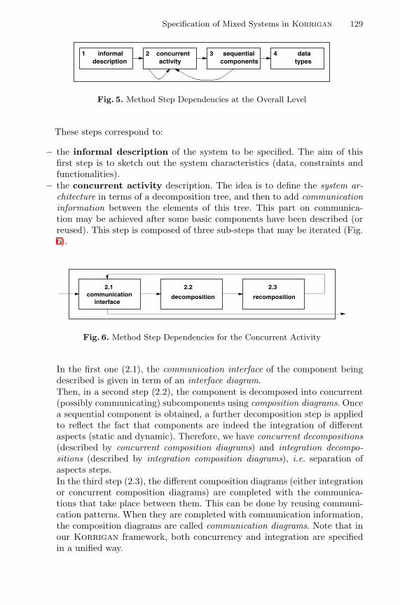
Specification of Mixed Systems in Korrigan 129
1 informaldescription
3 sequentialcomponents
4 datatypes
2 concurrentactivity
Fig. 5. Method Step Dependencies at the Overall Level
These steps correspond to:
– the informal description of the system to be specified. The aim of thisfirst step is to sketch out the system characteristics (data, constraints andfunctionalities).
– the concurrent activity description. The idea is to define the system ar-chitecture in terms of a decomposition tree, and then to add communicationinformation between the elements of this tree. This part on communica-tion may be achieved after some basic components have been described (orreused). This step is composed of three sub-steps that may be iterated (Fig.6).
communication interface
decomposition recomposition
2.1 2.2 2.3
Fig. 6. Method Step Dependencies for the Concurrent Activity
In the first one (2.1), the communication interface of the component beingdescribed is given in term of an interface diagram.Then, in a second step (2.2), the component is decomposed into concurrent(possibly communicating) subcomponents using composition diagrams. Oncea sequential component is obtained, a further decomposition step is appliedto reflect the fact that components are indeed the integration of differentaspects (static and dynamic). Therefore, we have concurrent decompositions(described by concurrent composition diagrams) and integration decompo-sitions (described by integration composition diagrams), i.e. separation ofaspects steps.In the third step (2.3), the different composition diagrams (either integrationor concurrent composition diagrams) are completed with the communica-tions that take place between them. This can be done by reusing communi-cation patterns. When they are completed with communication information,the composition diagrams are called communication diagrams. Note that inour Korrigan framework, both concurrency and integration are specifiedin a unified way.
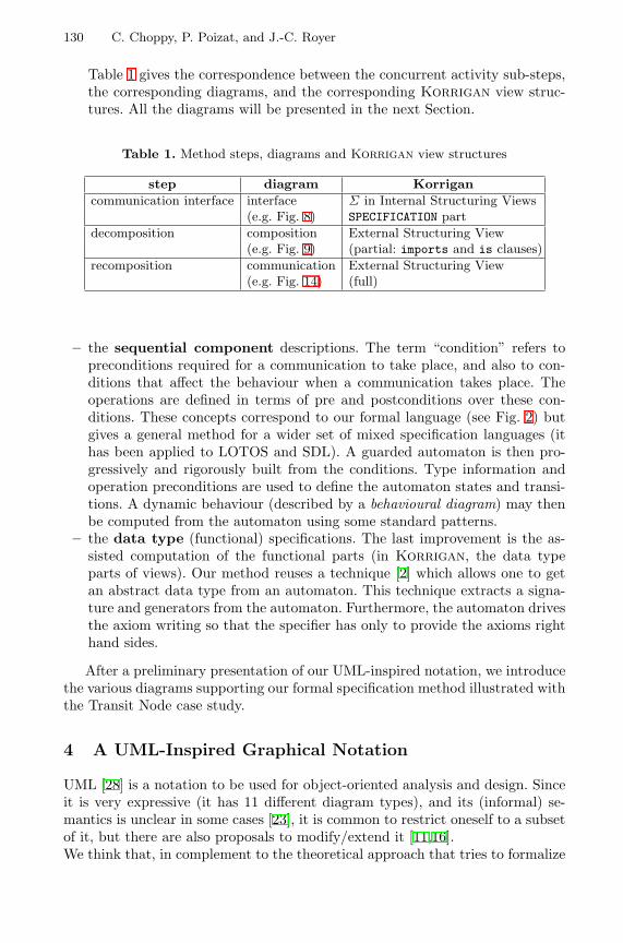
130 C. Choppy, P. Poizat, and J.-C. Royer
Table 1 gives the correspondence between the concurrent activity sub-steps,the corresponding diagrams, and the corresponding Korrigan view struc-tures. All the diagrams will be presented in the next Section.
Table 1. Method steps, diagrams and Korrigan view structures
step diagram Korrigancommunication interface interface Σ in Internal Structuring Views
(e.g. Fig. 8) SPECIFICATION partdecomposition composition External Structuring View
(e.g. Fig. 9) (partial: imports and is clauses)recomposition communication External Structuring View
(e.g. Fig. 14) (full)
– the sequential component descriptions. The term “condition” refers topreconditions required for a communication to take place, and also to con-ditions that affect the behaviour when a communication takes place. Theoperations are defined in terms of pre and postconditions over these con-ditions. These concepts correspond to our formal language (see Fig. 2) butgives a general method for a wider set of mixed specification languages (ithas been applied to LOTOS and SDL). A guarded automaton is then pro-gressively and rigorously built from the conditions. Type information andoperation preconditions are used to define the automaton states and transi-tions. A dynamic behaviour (described by a behavioural diagram) may thenbe computed from the automaton using some standard patterns.
– the data type (functional) specifications. The last improvement is the as-sisted computation of the functional parts (in Korrigan, the data typeparts of views). Our method reuses a technique [2] which allows one to getan abstract data type from an automaton. This technique extracts a signa-ture and generators from the automaton. Furthermore, the automaton drivesthe axiom writing so that the specifier has only to provide the axioms righthand sides.
After a preliminary presentation of our UML-inspired notation, we introducethe various diagrams supporting our formal specification method illustrated withthe Transit Node case study.
4 A UML-Inspired Graphical Notation
UML [28] is a notation to be used for object-oriented analysis and design. Sinceit is very expressive (it has 11 different diagram types), and its (informal) se-mantics is unclear in some cases [23], it is common to restrict oneself to a subsetof it, but there are also proposals to modify/extend it [11,16].We think that, in complement to the theoretical approach that tries to formalize
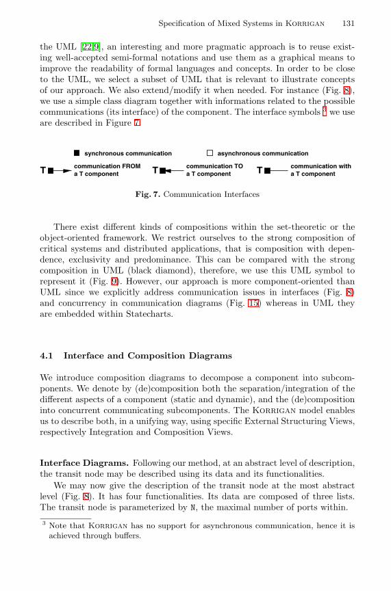
Specification of Mixed Systems in Korrigan 131
the UML [22,9], an interesting and more pragmatic approach is to reuse exist-ing well-accepted semi-formal notations and use them as a graphical means toimprove the readability of formal languages and concepts. In order to be closeto the UML, we select a subset of UML that is relevant to illustrate conceptsof our approach. We also extend/modify it when needed. For instance (Fig. 8),we use a simple class diagram together with informations related to the possiblecommunications (its interface) of the component. The interface symbols 3 we useare described in Figure 7.
synchronous communication asynchronous communication
communication TOa T componentTcommunication FROM
a T componentT communication witha T componentT
Fig. 7. Communication Interfaces
There exist different kinds of compositions within the set-theoretic or theobject-oriented framework. We restrict ourselves to the strong composition ofcritical systems and distributed applications, that is composition with depen-dence, exclusivity and predominance. This can be compared with the strongcomposition in UML (black diamond), therefore, we use this UML symbol torepresent it (Fig. 9). However, our approach is more component-oriented thanUML since we explicitly address communication issues in interfaces (Fig. 8)and concurrency in communication diagrams (Fig. 15) whereas in UML theyare embedded within Statecharts.
4.1 Interface and Composition Diagrams
We introduce composition diagrams to decompose a component into subcom-ponents. We denote by (de)composition both the separation/integration of thedifferent aspects of a component (static and dynamic), and the (de)compositioninto concurrent communicating subcomponents. The Korrigan model enablesus to describe both, in a unifying way, using specific External Structuring Views,respectively Integration and Composition Views.
Interface Diagrams. Following our method, at an abstract level of description,the transit node may be described using its data and its functionalities.
We may now give the description of the transit node at the most abstractlevel (Fig. 8). It has four functionalities. Its data are composed of three lists.The transit node is parameterized by N, the maximal number of ports within.
3 Note that Korrigan has no support for asynchronous communication, hence it isachieved through buffers.
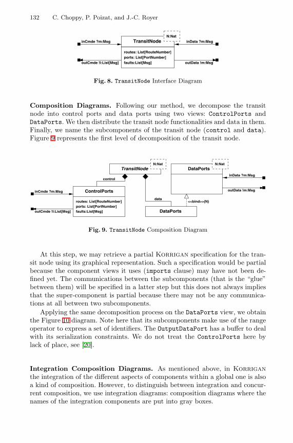
132 C. Choppy, P. Poizat, and J.-C. Royer
TransitNode
outCmde !l:List[Msg]
inCmde ?m:Msg
routes: List[RouteNumber]ports: List[PortNumber]faults:List[Msg]
inData ?m:Msg
outData !m:Msg
N:Nat
Fig. 8. TransitNode Interface Diagram
Composition Diagrams. Following our method, we decompose the transitnode into control ports and data ports using two views: ControlPorts andDataPorts. We then distribute the transit node functionalities and data in them.Finally, we name the subcomponents of the transit node (control and data).Figure 9 represents the first level of decomposition of the transit node.
TransitNode
ControlPorts
routes: List[RouteNumber]ports: List[PortNumber]faults:List[Msg]
inCmde ?m:Msg
outCmde !l:List[Msg]
control
DataPorts
DataPorts
inData ?m:Msg
outData !m:Msg
<<bind>>(N)data
N:Nat N:Nat
Fig. 9. TransitNode Composition Diagram
At this step, we may retrieve a partial Korrigan specification for the tran-sit node using its graphical representation. Such a specification would be partialbecause the component views it uses (imports clause) may have not been de-fined yet. The communications between the subcomponents (that is the “glue”between them) will be specified in a latter step but this does not always impliesthat the super-component is partial because there may not be any communica-tions at all between two subcomponents.
Applying the same decomposition process on the DataPorts view, we obtainthe Figure 10 diagram. Note here that its subcomponents make use of the rangeoperator to express a set of identifiers. The OutputDataPort has a buffer to dealwith its serialization constraints. We do not treat the ControlPorts here bylack of place, see [20].
Integration Composition Diagrams. As mentioned above, in Korriganthe integration of the different aspects of components within a global one is alsoa kind of composition. However, to distinguish between integration and concur-rent composition, we use integration diagrams: composition diagrams where thenames of the integration components are put into gray boxes.
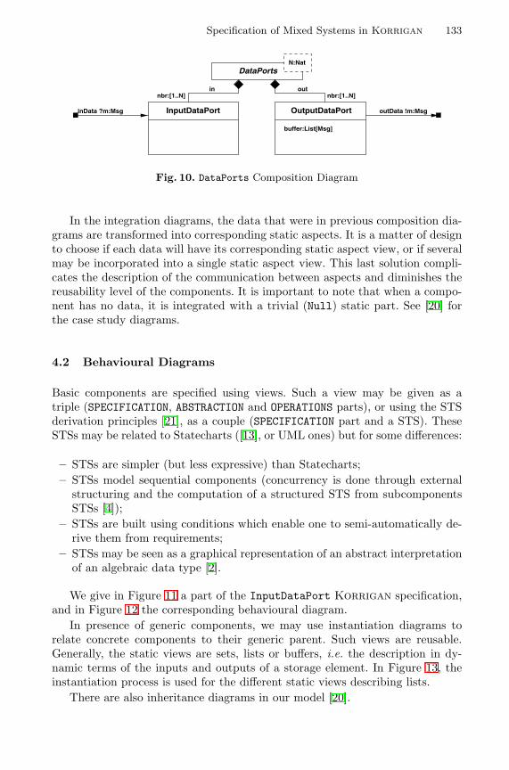
Specification of Mixed Systems in Korrigan 133
DataPorts
OutputDataPortInputDataPortinData ?m:Msg outData !m:Msg
buffer:List[Msg]
nbr:[1..N]nbr:[1..N]in out
N:Nat
Fig. 10. DataPorts Composition Diagram
In the integration diagrams, the data that were in previous composition dia-grams are transformed into corresponding static aspects. It is a matter of designto choose if each data will have its corresponding static aspect view, or if severalmay be incorporated into a single static aspect view. This last solution compli-cates the description of the communication between aspects and diminishes thereusability level of the components. It is important to note that when a compo-nent has no data, it is integrated with a trivial (Null) static part. See [20] forthe case study diagrams.
4.2 Behavioural Diagrams
Basic components are specified using views. Such a view may be given as atriple (SPECIFICATION, ABSTRACTION and OPERATIONS parts), or using the STSderivation principles [21], as a couple (SPECIFICATION part and a STS). TheseSTSs may be related to Statecharts ([13], or UML ones) but for some differences:
– STSs are simpler (but less expressive) than Statecharts;– STSs model sequential components (concurrency is done through external
structuring and the computation of a structured STS from subcomponentsSTSs [4]);
– STSs are built using conditions which enable one to semi-automatically de-rive them from requirements;
– STSs may be seen as a graphical representation of an abstract interpretationof an algebraic data type [2].
We give in Figure 11 a part of the InputDataPort Korrigan specification,and in Figure 12 the corresponding behavioural diagram.
In presence of generic components, we may use instantiation diagrams torelate concrete components to their generic parent. Such views are reusable.Generally, the static views are sets, lists or buffers, i.e. the description in dy-namic terms of the inputs and outputs of a storage element. In Figure 13, theinstantiation process is used for the different static views describing lists.
There are also inheritance diagrams in our model [20].
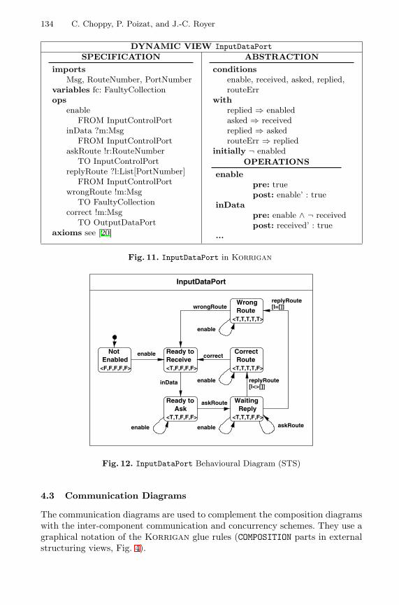
134 C. Choppy, P. Poizat, and J.-C. Royer
DYNAMIC VIEW InputDataPortSPECIFICATION
importsMsg, RouteNumber, PortNumber
variables fc: FaultyCollectionops
enableFROM InputControlPort
inData ?m:MsgFROM InputControlPort
askRoute !r:RouteNumberTO InputControlPort
replyRoute ?l:List[PortNumber]FROM InputControlPort
wrongRoute !m:MsgTO FaultyCollection
correct !m:MsgTO OutputDataPort
axioms see [20]
ABSTRACTION
conditionsenable, received, asked, replied,routeErr
withreplied ⇒ enabledasked ⇒ receivedreplied ⇒ askedrouteErr ⇒ replied
initially ¬ enabledOPERATIONS
enablepre: truepost: enable’ : true
inDatapre: enable ∧ ¬ receivedpost: received’ : true
...
Fig. 11. InputDataPort in Korrigan
NotEnabled
Ready toReceive
Ready toAsk
WaitingReply
Route
Route
<F,F,F,F,F> <T,F,F,F,F>
<T,T,F,F,F> <T,T,T,F,F>
enable
enable enable
enable
enable
inData
askRoute
askRoute
<T,T,T,T,F>
Correct
Wrong
<T,T,T,T,T>
wrongRoute
correct
[l=[]]replyRoute
[l<>[]]replyRoute
InputDataPort
Fig. 12. InputDataPort Behavioural Diagram (STS)
4.3 Communication Diagrams
The communication diagrams are used to complement the composition diagramswith the inter-component communication and concurrency schemes. They use agraphical notation of the Korrigan glue rules (COMPOSITION parts in externalstructuring views, Fig. 4).
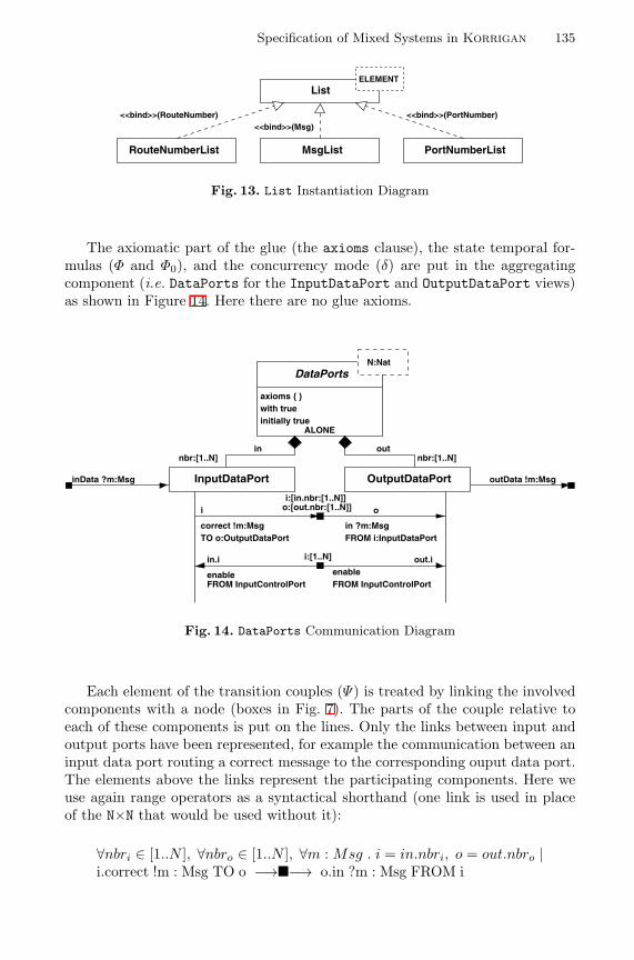
Specification of Mixed Systems in Korrigan 135
PortNumberListMsgList
List
<<bind>>(RouteNumber)<<bind>>(Msg)
<<bind>>(PortNumber)
RouteNumberList
ELEMENT
Fig. 13. List Instantiation Diagram
The axiomatic part of the glue (the axioms clause), the state temporal for-mulas (Φ and Φ0), and the concurrency mode (δ) are put in the aggregatingcomponent (i.e. DataPorts for the InputDataPort and OutputDataPort views)as shown in Figure 14. Here there are no glue axioms.
DataPorts
ALONE
axioms { }with trueinitially true
OutputDataPortInputDataPortinData ?m:Msg outData !m:Msg
correct !m:MsgTO o:OutputDataPort
in ?m:MsgFROM i:InputDataPort
i:[1..N] out.iin.i
enableFROM InputControlPort FROM InputControlPort
enable
i:[in.nbr:[1..N]]o:[out.nbr:[1..N]]i o
nbr:[1..N]nbr:[1..N]in out
N:Nat
Fig. 14. DataPorts Communication Diagram
Each element of the transition couples (Ψ) is treated by linking the involvedcomponents with a node (boxes in Fig. 7). The parts of the couple relative toeach of these components is put on the lines. Only the links between input andoutput ports have been represented, for example the communication between aninput data port routing a correct message to the corresponding ouput data port.The elements above the links represent the participating components. Here weuse again range operators as a syntactical shorthand (one link is used in placeof the N×N that would be used without it):
∀nbri ∈ [1..N ], ∀nbro ∈ [1..N ], ∀m : Msg . i = in.nbri, o = out.nbro |i.correct !m : Msg TO o −→�−→ o.in ?m : Msg FROM i
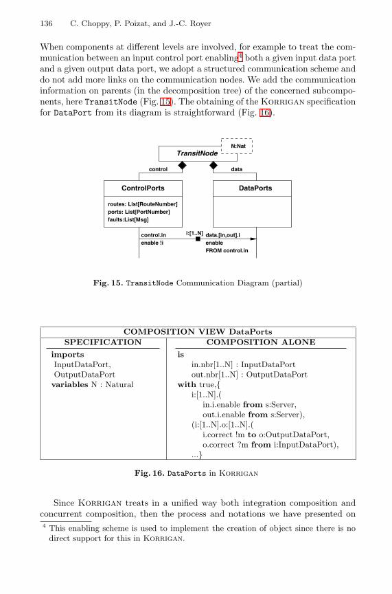
136 C. Choppy, P. Poizat, and J.-C. Royer
When components at different levels are involved, for example to treat the com-munication between an input control port enabling4 both a given input data portand a given output data port, we adopt a structured communication scheme anddo not add more links on the communication nodes. We add the communicationinformation on parents (in the decomposition tree) of the concerned subcompo-nents, here TransitNode (Fig. 15). The obtaining of the Korrigan specificationfor DataPort from its diagram is straightforward (Fig. 16).
control.inenable !i
FROM control.inenabledata.[in,out].ii:[1..N]
TransitNode
ControlPorts DataPorts
routes: List[RouteNumber]ports: List[PortNumber]faults:List[Msg]
control data
N:Nat
Fig. 15. TransitNode Communication Diagram (partial)
COMPOSITION VIEW DataPortsSPECIFICATION
importsInputDataPort,OutputDataPortvariables N : Natural
COMPOSITION ALONE
isin.nbr[1..N] : InputDataPortout.nbr[1..N] : OutputDataPort
with true,{i:[1..N].(
in.i.enable from s:Server,out.i.enable from s:Server),
(i:[1..N].o:[1..N].(i.correct !m to o:OutputDataPort,o.correct ?m from i:InputDataPort),
...}
Fig. 16. DataPorts in Korrigan
Since Korrigan treats in a unified way both integration composition andconcurrent composition, then the process and notations we have presented on4 This enabling scheme is used to implement the creation of object since there is no
direct support for this in Korrigan.
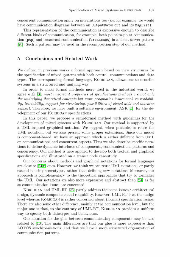
Specification of Mixed Systems in Korrigan 137
concurrent communication apply on integrations too (i.e. for example, we wouldhave communication diagrams between an OutputDataPort and its MsgList).
This representation of the communication is expressive enough to describedifferent kinds of communication, for example, both point-to-point communica-tion (ptp) and broadcast communication (broadcast) in a client-server pattern[20]. Such a pattern may be used in the recomposition step of our method.
5 Conclusions and Related Work
We defined in previous works a formal approach based on view structures forthe specification of mixed systems with both control, communications and datatypes. The corresponding formal language, Korrigan, allows one to describesystems in a structured and unifying way.
In order to make formal methods more used in the industrial world, weagree with [3]: most important properties of specifications methods are not onlythe underlying theoretical concepts but more pragmatics issues such as readabil-ity, tractability, support for structuring, possibilities of visual aids and machinesupport. Therefore, we have built a software environment, ASK [5], for the de-velopment of our Korrigan specifications.
In this paper, we propose a semi-formal method with guidelines for thedevelopment of mixed systems with Korrigan. Our method is supported bya UML-inspired graphical notation. We suggest, when possible, to reuse theUML notation, but we also present some proper extensions. Since our modelis component-based, we have an approach which is rather different from UMLon communications and concurrent aspects. Thus we also describe specific nota-tions to define dynamic interfaces of components, communications patterns andconcurrency. Our method is here applied to develop both textual and graphicalspecifications and illustrated on a transit node case-study.
Our concerns about methods and graphical notations for formal languagesare close to [24,6] ones. However, we think we can reuse UML notations, or partlyextend it using stereotypes, rather than defining new notations. Moreover, ourapproach is complementary to the theoretical approaches that try to formalizethe UML. Our notations are also more expressive and abstract than [24] as faras communication issues are concerned.
Korrigan and UML-RT [25] partly address the same issues : architecturaldesign, dynamic components and reusability. However, UML-RT is at the designlevel whereas Korrigan is rather concerned about (formal) specification issues.There are also some other difference, mainly at the communication level, but themajor one is that, to the contrary of UML-RT, Korrigan provides a uniformway to specify both datatypes and behaviours.
Our notation for the glue between communicating components may be alsorelated to [10]. The main differences are that our glue is more expressive thanLOTOS synchronizations, and that we have a more structured organization ofcommunication patterns.
138 C. Choppy, P. Poizat, and J.-C. Royer
We are now working on validation and verification procedures for our Kor-rigan specifications. Due to the use of STS, i.e. Symbolic Transition Systems,such procedures have to be adapted [15,26]. We also investigate the automatictranslation of Korrigan specifications into PVS following the [1] methodology.
References
1. Michel Allemand. Verification of properties involving logical and physical tim-ing features. In Genie Logiciel & Ingenierie de Systemes & leurs Applications,ICSSEA’2000, 2000.
2. Pascal Andre and Jean-Claude Royer. A First Algebraic Approach to Heteroge-neous Software Systems. 14th International Workshop on Algebraic DevelopmentTechniques (WADT’99), Bonas, France, 1999.
3. M. Broy. Specification and top down design of distributed systems. In H. Ehrig,C. Floyd, M. Nivat, and J. Thatcher, editors, TAPSOFT’85, volume 185 of LectureNotes in Computer Science, pages 4–28. Springer-Verlag, 1985.
4. Christine Choppy, Pascal Poizat, and Jean-Claude Royer. A Global Semantics forViews. In T. Rus, editor, International Conference on Algebraic Methodology AndSoftware Technology (AMAST’2000), volume 1816 of Lecture Notes in ComputerScience, pages 165–180. Springer-Verlag, 2000.
5. Christine Choppy, Pascal Poizat, and Jean-Claude Royer. The Korrigan Envi-ronment. Journal of Universal Computer Science, 2001. Special issue: Tools forSystem Design and Verification, ISSN: 0948-6968. to appear.
6. Eva Coscia and Gianna Reggio. JTN: A Java-Targeted Graphic Formal Notationfor Reactive and Concurrent Systems. In Jean-Pierre Finance, editor, FundamentalApproaches to Software Engineering (FASE’99), volume 1577 of Lecture Notes inComputer Science, pages 77–97. Springer-Verlag, 1999.
7. Jan Ellsberger, Dieter Hogrefe, and Amardeo Sarma. SDL : Formal Object-orientedLanguage for Communicating Systems. Prentice-Hall, 1997.
8. C. Fischer. CSP-OZ: a combination of Object-Z and CSP. In H. Bowman andJ. Derrick, editors, Proc. 2nd IFIP Workshop on Formal Methods for Open Object-Based Distributed Systems (FMOODS), pages 423–438, Canterbury, UK, 1997.Chapman & Hall.
9. R. France and B. Rumpe, editors. UML’99 – The Unified Modelling Language,volume 1723 of Lecture Notes in Computer Science. Springer-Verlag, 1999.
10. Hubert Garavel and Mihaela Sighireanu. A Graphical Parallel Composition Opera-tor for Process Algebras. In Joint International Conference on Formal DescriptionTechniques for Distributed Systems and Communication Protocols, and ProtocolSpecification, Testing, and Verification (FORTE/PSTV’99), 1999.
11. Gianna Reggio and Egidio Astesiano. An extension of UML for modelling the nonpurely reactive behaviour of active objects. Semi-Formal and Formal SpecificationTechniques for Software Systems, Dagstuhl Seminar 00411, Report No. 288, H.Ehrig, G. Engels, F. Orejas, M. Wirsing, October 2000.
12. Wolfgang Grieskamp, Maritta Heisel, and Heiko Dorr. Specifying Embedded Sys-tems with Statecharts and Z: An Agenda for Cyclic Software Components. InEgidio Astesiano, editor, FASE’98, volume 1382 of Lecture Notes in ComputerScience, pages 88–106. Springer-Verlag, 1998.
13. David Harel. On Visual Formalisms. Communications of the ACM, 31(5):514–530,1988.
Specification of Mixed Systems in Korrigan 139
14. Maritta Heisel. Agendas – A Concept to Guide Software Development Activities.In R. N. Horspool, editor, Systems Implementation 2000, pages 19–32. Chapman& Hall, 1998.
15. M. Hennessy and H. Lin. Symbolic Bisimulations. Theoretical Computer Science,138(2):353–389, 1995.
16. Bogumila Hnatkowska and Huzar Zbigniew. Extending the UML with a MulticastSynchronisation. In T. Clark, editor, Proceedings of the third Rigorous Object-Oriented Methods Workshop (ROOM), BCS eWics, ISBN: 1-902505-38-7, 2000.
17. ISO/IEC. LOTOS: A Formal Description Technique based on the Temporal Or-dering of Observational Behaviour. ISO/IEC 8807, International Organization forStandardization, 1989.
18. Leslie Lamport. The Temporal Logic of Actions. ACM Transactions on Program-ming Languages and Systems, 16(3):872–923, 1994.
19. Jose Meseguer. Rewriting logic as a semantic framework for concurrency: a progressreport. In CONCUR’96 : Concurrency Theory, volume 1119 of Lecture Notes inComputer Science, pages 331–372, Pisa, Italy, 1996.
20. Pascal Poizat. Korrigan: a Formalism and a Method for the Structured FormalSpecification of Mixed Systems. PhD thesis, Institut de Recherche en Informatiquede Nantes, Universite de Nantes, December 2000. in French.
21. Pascal Poizat, Christine Choppy, and Jean-Claude Royer. From Informal Require-ments to COOP: a Concurrent Automata Approach. In J.M. Wing, J. Woodcock,and J. Davies, editors, FM’99 - Formal Methods, World Congress on Formal Meth-ods in the Development of Computing Systems, volume 1709 of Lecture Notes inComputer Science, pages 939–962, Toulouse, France, 1999. Springer-Verlag.
22. G. Reggio, M. Cerioli, and E. Astesiano. An Algebraic Semantics of UML Sup-porting its Multiview Approach. In D. Heylen, A. Nijholt, and G. Scollo, editors,Twente Workshop on Language Technology, AMiLP 2000, 2000.
23. G. Reggio and R. Wieringa. Thirty one Problems in the Semantics of UML 1.3Dynamics. In OOPSLA’99 workshop ”Rigorous Modelling and Analysis of theUML: Challenges and Limitations”, 1999.
24. Gianna Reggio and Mauro Larosa. A graphic notation for formal specificationsof dynamic systems. In J. Fitzgerald, C. B. Jones, and P. Lucas, editors, FormalMethods Europe (FME’97), volume 1313 of Lecture Notes in Computer Science,pages 40–61. Springer-Verlag, 1997.
25. Bran Selic and Jim Rumbaugh. Using UML for Modeling Complex Real-TimeSystems. Technical report, Rational Software Corp., 1998.
26. Carron Shankland, Muffy Thomas, and Ed Brinksma. Symbolic Bisimulation forFull LOTOS. In Algebraic Methodology and Software Technology (AMAST’97), vol-ume 1349 of Lecture Notes in Computer Science, pages 479–493. Springer-Verlag,1997.
27. Graeme Smith. A Semantic Integration of Object-Z and CSP for the Specificationof Concurrent Systems. In J. Fitzgerald, C. B. Jones, and P. Lucas, editors, FormalMethods Europe (FME’97), volume 1313 of Lecture Notes in Computer Science,pages 62–81. Springer-Verlag, 1997.
28. Rational Software. Unified Modeling Language, Version 1.3. Technical report,Rational Software Corp., http://www.rational.com/uml, June 1999.
29. Kenneth J. Turner, editor. Using Formal Description Techniques, An introductionto Estelle, LOTOS and SDL. Wiley, 1993.
30. C. A. Vissers, G. Scollo, M. Van Sinderen, and E. Brinksma. Specification Stylesin Distributed Systems Design and Verification. Theoretical Computer Science,89(1):179–206, 1991.
On Use Cases and Their Relationships in theUnified Modelling Language
Perdita Stevens?
Division of InformaticsUniversity of Edinburgh
Abstract. In the Unified Modelling Language, use cases are providedas a way of summarising the requirements on a system. They are de-fined informally as specifications of sets of sequences of actions, and sev-eral relationships between use cases are informally defined. Dependable,tool-supported software development necessitates precise definitions ofall these concepts but the topic has so far received little attention in theliterature, beyond what is present in Catalysis. This paper explores howthese notions can be formalised whilst staying as close as possible to theUML standard, makes some suggestions and raises further questions.
1 Introduction
The Unified Modelling Language has been widely adopted as a standard languagefor modelling the design of (software) systems. Nevertheless, certain aspects ofUML are not yet defined precisely. This paper is concerned with one such aspect:use cases and their relationships. The relationship between a use case and itsconstituent actions, and especially the implications of this for the relationshipsbetween use cases, are a particularly frequent source of confusion; we have notreached the point where a tool could support the use of use cases without makingmajor decisions concerning how to interpret the UML standard.
In this paper we discuss how use cases and their relationships may be for-malised. We aim to use the minimum of formal machinery possible; so, for ex-ample, we model use cases as plain labelled transition systems, rather than asprocesses in some particular process algebra. 1 A major aim of this work is to befaithful to the UML standard wherever possible: UML is a hard-fought compro-mise and it seems sensible to try to formalise what is currently intended ratherthan, or at least before, suggesting improvements to that intention. There are,however, several points at which our formalisation attempt forces us to concludethat the UML standard needs amendment.? Email: [email protected]. Fax: +44 131 667 72091 Given that process algebras are typically explained and given semantics using la-
belled transition systems, working directly with the LTSs is indeed “more basic”,requiring strictly less machinery: it gives us a well-defined notion of what it wouldmean for an alternative translation into a process algebra to be consistent with ourdecisions, without requiring us to enter into the process algebra wars.
H. Hussmann (Ed.): FASE 2001, LNCS 2029, pp. 140–155, 2001.c© Springer-Verlag Berlin Heidelberg 2001
On Use Cases and Their Relationships in the Unified Modelling Language 141
The paper is structured as follows. The remainder of this section includes anote on standards and terminology, and a brief discussion of related work. InSect. 2, we discuss the way UML sees use cases as made up of constituent actions.We model use cases and raise questions concerning their relationship with thesystem that provides them. In Sect. 3, we go on to discuss the “dependency”relationships between use cases, covering �include� in detail. In Sect. 4 weconsider the more controversial relationship, generalisation between use cases;here we fail to find an adequately simple formalisation of UML’s intentions,and indeed expose some problems with even the informal description. Finally inSect. 5 we conclude and discuss future work.
1.1 Note on Standards and Terminology
This paper is based on UML1.3, the current standard at the time of writing. It ishoped that this work may feed into the ongoing construction of UML2.0, a majoraim of which is to increase the precision of UML. The reader is assumed to befamiliar with UML and should, in particular, be aware that UML’s treatment ofuse cases changed significantly between versions 1.1 and 1.3, in response to criti-cisms of UML1.1’s treatment: many UML books, however, still refer to UML1.1.We will refer to [10] as evidence of the intentions of some of the authors of UML,but it is important to note that the definition of UML is the OMG standard[7], not what is contained in any UML book. We cite material from [7] by page;thus, [7] (3-90) indicates page 90 of Sect. 3 of the UML standard, that is, of theNotation Guide.
Catalysis is described principally in [5]. Readers need to be aware that thenotation used there, though UML-like, is not standard UML; and also thatsome technical terms have different meanings in UML and in Catalysis. Unlessotherwise stated, this paper uses the UML notions.
1.2 Related Work
Perhaps surprisingly, given the frequency of mailing list questions and informaldiscussions of use cases and their relationships, there seems to be no previouswork that formalises use cases in a way comparable to the present. In prac-tice, many use case experts such as Alistair Cockburn (see e.g. [4]) advocatean informal approach to use cases, in which use cases are simply considered astasks. This is arguably the right approach for a practitioner to take; but even so,see Sect. 5 for Cockburn’s comment on deficiencies in current understanding ofgeneralisation of use cases. The closest comparator to the present work is Gun-nar Overgaard’s recent PhD thesis [9], which reached the author too late to beconsidered in detail here. At first sight, a major difference is that Overgaard’s for-malisation does not seem to consider fully the implications of the dynamic choicesthat are made by the parties to a use case. The thesis supercedes an earlier paper[8], which formalised some aspects of use cases in UML1.1 and was influential onthe development of UML1.3, considered here. The authors of the development
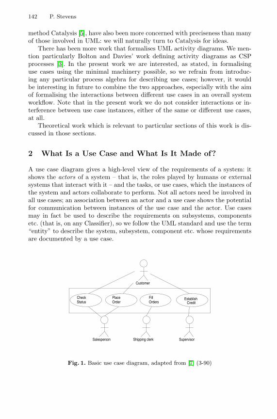
142 P. Stevens
method Catalysis [5], have also been more concerned with preciseness than manyof those involved in UML: we will naturally turn to Catalysis for ideas.
There has been more work that formalises UML activity diagrams. We men-tion particularly Bolton and Davies’ work defining activity diagrams as CSPprocesses [3]. In the present work we are interested, as stated, in formalisinguse cases using the minimal machinery possible, so we refrain from introduc-ing any particular process algebra for describing use cases; however, it wouldbe interesting in future to combine the two approaches, especially with the aimof formalising the interactions between different use cases in an overall systemworkflow. Note that in the present work we do not consider interactions or in-terference between use case instances, either of the same or different use cases,at all.
Theoretical work which is relevant to particular sections of this work is dis-cussed in those sections.
2 What Is a Use Case and What Is It Made of?
A use case diagram gives a high-level view of the requirements of a system: itshows the actors of a system – that is, the roles played by humans or externalsystems that interact with it – and the tasks, or use cases, which the instances ofthe system and actors collaborate to perform. Not all actors need be involved inall use cases; an association between an actor and a use case shows the potentialfor communication between instances of the use case and the actor. Use casesmay in fact be used to describe the requirements on subsystems, componentsetc. (that is, on any Classifier), so we follow the UML standard and use the term“entity” to describe the system, subsystem, component etc. whose requirementsare documented by a use case.
CheckStatus
PlaceOrder
FillOrders Credit
Establish
Customer
Salesperson Shipping clerk Supervisor
Fig. 1. Basic use case diagram, adapted from [7] (3-90)
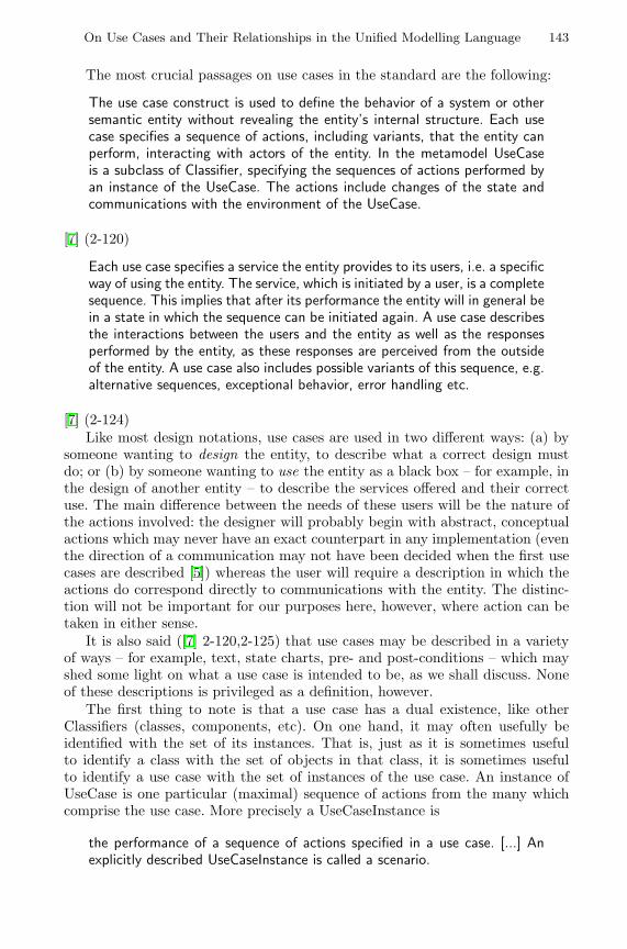
On Use Cases and Their Relationships in the Unified Modelling Language 143
The most crucial passages on use cases in the standard are the following:
The use case construct is used to define the behavior of a system or othersemantic entity without revealing the entity’s internal structure. Each usecase specifies a sequence of actions, including variants, that the entity canperform, interacting with actors of the entity. In the metamodel UseCaseis a subclass of Classifier, specifying the sequences of actions performed byan instance of the UseCase. The actions include changes of the state andcommunications with the environment of the UseCase.
[7] (2-120)
Each use case specifies a service the entity provides to its users, i.e. a specificway of using the entity. The service, which is initiated by a user, is a completesequence. This implies that after its performance the entity will in general bein a state in which the sequence can be initiated again. A use case describesthe interactions between the users and the entity as well as the responsesperformed by the entity, as these responses are perceived from the outsideof the entity. A use case also includes possible variants of this sequence, e.g.alternative sequences, exceptional behavior, error handling etc.
[7] (2-124)Like most design notations, use cases are used in two different ways: (a) by
someone wanting to design the entity, to describe what a correct design mustdo; or (b) by someone wanting to use the entity as a black box – for example, inthe design of another entity – to describe the services offered and their correctuse. The main difference between the needs of these users will be the nature ofthe actions involved: the designer will probably begin with abstract, conceptualactions which may never have an exact counterpart in any implementation (eventhe direction of a communication may not have been decided when the first usecases are described [5]) whereas the user will require a description in which theactions do correspond directly to communications with the entity. The distinc-tion will not be important for our purposes here, however, where action can betaken in either sense.
It is also said ([7] 2-120,2-125) that use cases may be described in a varietyof ways – for example, text, state charts, pre- and post-conditions – which mayshed some light on what a use case is intended to be, as we shall discuss. Noneof these descriptions is privileged as a definition, however.
The first thing to note is that a use case has a dual existence, like otherClassifiers (classes, components, etc). On one hand, it may often usefully beidentified with the set of its instances. That is, just as it is sometimes usefulto identify a class with the set of objects in that class, it is sometimes usefulto identify a use case with the set of instances of the use case. An instance ofUseCase is one particular (maximal) sequence of actions from the many whichcomprise the use case. More precisely a UseCaseInstance is
the performance of a sequence of actions specified in a use case. [...] Anexplicitly described UseCaseInstance is called a scenario.
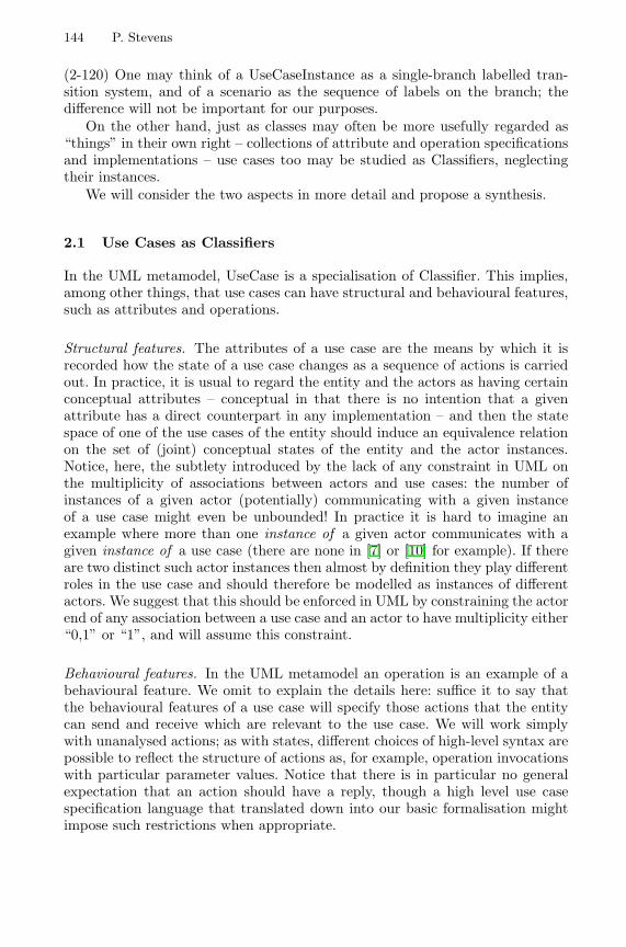
144 P. Stevens
(2-120) One may think of a UseCaseInstance as a single-branch labelled tran-sition system, and of a scenario as the sequence of labels on the branch; thedifference will not be important for our purposes.
On the other hand, just as classes may often be more usefully regarded as“things” in their own right – collections of attribute and operation specificationsand implementations – use cases too may be studied as Classifiers, neglectingtheir instances.
We will consider the two aspects in more detail and propose a synthesis.
2.1 Use Cases as Classifiers
In the UML metamodel, UseCase is a specialisation of Classifier. This implies,among other things, that use cases can have structural and behavioural features,such as attributes and operations.
Structural features. The attributes of a use case are the means by which it isrecorded how the state of a use case changes as a sequence of actions is carriedout. In practice, it is usual to regard the entity and the actors as having certainconceptual attributes – conceptual in that there is no intention that a givenattribute has a direct counterpart in any implementation – and then the statespace of one of the use cases of the entity should induce an equivalence relationon the set of (joint) conceptual states of the entity and the actor instances.Notice, here, the subtlety introduced by the lack of any constraint in UML onthe multiplicity of associations between actors and use cases: the number ofinstances of a given actor (potentially) communicating with a given instanceof a use case might even be unbounded! In practice it is hard to imagine anexample where more than one instance of a given actor communicates with agiven instance of a use case (there are none in [7] or [10] for example). If thereare two distinct such actor instances then almost by definition they play differentroles in the use case and should therefore be modelled as instances of differentactors. We suggest that this should be enforced in UML by constraining the actorend of any association between a use case and an actor to have multiplicity either“0,1” or “1”, and will assume this constraint.
Behavioural features. In the UML metamodel an operation is an example of abehavioural feature. We omit to explain the details here: suffice it to say thatthe behavioural features of a use case will specify those actions that the entitycan send and receive which are relevant to the use case. We will work simplywith unanalysed actions; as with states, different choices of high-level syntax arepossible to reflect the structure of actions as, for example, operation invocationswith particular parameter values. Notice that there is in particular no generalexpectation that an action should have a reply, though a high level use casespecification language that translated down into our basic formalisation mightimpose such restrictions when appropriate.
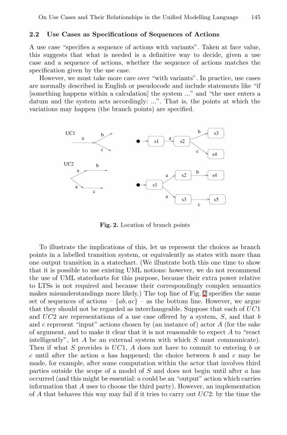
On Use Cases and Their Relationships in the Unified Modelling Language 145
2.2 Use Cases as Specifications of Sequences of Actions
A use case “specifies a sequence of actions with variants”. Taken at face value,this suggests that what is needed is a definitive way to decide, given a usecase and a sequence of actions, whether the sequence of actions matches thespecification given by the use case.
However, we must take more care over “with variants”. In practice, use casesare normally described in English or pseudocode and include statements like “if[something happens within a calculation] the system ...” and “the user enters adatum and the system acts accordingly: ...”. That is, the points at which thevariations may happen (the branch points) are specified.
s1
s1 s2
s2
s3 s5
s4
s4
s3b
c
b
c
a
a
ab
c
a
a
c
b
aUC1
UC2
Fig. 2. Location of branch points
To illustrate the implications of this, let us represent the choices as branchpoints in a labelled transition system, or equivalently as states with more thanone output transition in a statechart. (We illustrate both this one time to showthat it is possible to use existing UML notions: however, we do not recommendthe use of UML statecharts for this purpose, because their extra power relativeto LTSs is not required and because their correspondingly complex semanticsmakes misunderstandings more likely.) The top line of Fig. 2 specifies the sameset of sequences of actions – {ab, ac} – as the bottom line. However, we arguethat they should not be regarded as interchangeable. Suppose that each of UC1and UC2 are representations of a use case offered by a system, S, and that band c represent “input” actions chosen by (an instance of) actor A (for the sakeof argument, and to make it clear that it is not reasonable to expect A to “reactintelligently”, let A be an external system with which S must communicate).Then if what S provides is UC1, A does not have to commit to entering b orc until after the action a has happened; the choice between b and c may bemade, for example, after some computation within the actor that involves thirdparties outside the scope of a model of S and does not begin until after a hasoccurred (and this might be essential: a could be an “output” action which carriesinformation that A uses to choose the third party). However, an implementationof A that behaves this way may fail if it tries to carry out UC2: by the time the
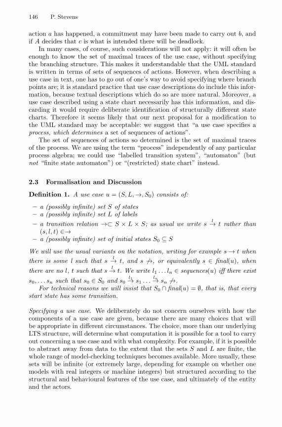
146 P. Stevens
action a has happened, a commitment may have been made to carry out b, andif A decides that c is what is intended there will be deadlock.
In many cases, of course, such considerations will not apply: it will often beenough to know the set of maximal traces of the use case, without specifyingthe branching structure. This makes it understandable that the UML standardis written in terms of sets of sequences of actions. However, when describing ause case in text, one has to go out of one’s way to avoid specifying where branchpoints are; it is standard practice that use case descriptions do include this infor-mation, because textual descriptions which do so are more natural. Moreover, ause case described using a state chart necessarily has this information, and dis-carding it would require deliberate identification of structurally different statecharts. Therefore it seems likely that our next proposal for a modification tothe UML standard may be acceptable: we suggest that “a use case specifies aprocess, which determines a set of sequences of actions”.
The set of sequences of actions so determined is the set of maximal tracesof the process. We are using the term “process” independently of any particularprocess algebra; we could use “labelled transition system”, “automaton” (butnot “finite state automaton”) or “(restricted) state chart” instead.
2.3 Formalisation and Discussion
Definition 1. A use case u = (S,L,→, S0) consists of:
– a (possibly infinite) set S of states– a (possibly infinite) set L of labels– a transition relation →⊂ S × L × S; as usual we write s l→ t rather than
(s, l, t) ∈→– a (possibly infinite) set of initial states S0 ⊆ S
We will use the usual variants on the notation, writing for example s → t whenthere is some l such that s l→ t, and s 6→, or equivalently s ∈ final(u), whenthere are no l, t such that s l→ t. We write l1 . . . ln ∈ sequences(u) iff there exists0, . . . sn such that s0 ∈ S0 and s0
l1→ s1 . . .ln→ sn 6→.
For technical reasons we will insist that S0 ∩ final(u) = ∅, that is, that everystart state has some transition.
Specifying a use case. We deliberately do not concern ourselves with how thecomponents of a use case are given, because there are many choices that willbe appropriate in different circumstances. The choice, more than our underlyingLTS structure, will determine what computation it is possible for a tool to carryout concerning a use case and with what complexity. For example, if it is possibleto abstract away from data to the extent that the sets S and L are finite, thewhole range of model-checking techniques becomes available. More usually, thesesets will be infinite (or extremely large, depending for example on whether onemodels with real integers or machine integers) but structured according to thestructural and behavioural features of the use case, and ultimately of the entityand the actors.
On Use Cases and Their Relationships in the Unified Modelling Language 147
Nevertheless, any way of giving the components should be expected to satisfya sanity condition that the state of the use case “contains no more informationthan” the states of the participants in the use case. Precisely:
Definition 2. Let u = (S,L,→, S0) be a use case for an entity with statespaceE in which the entity communicates with actors with statespaces A1 . . . An.2 Aquotient map of u is a surjective function
h : E ×A1 × . . . An → S.
A specification formalism should include such a quotient map for each use case.Most simply, if the statespace of the use case is constrained to be written interms of a subset of the attributes of the entity and actors involved, the obviousinduced quotient map might be assumed.
Why maximal traces? We have chosen to restrict attention to finite sequencesof actions, where no further action is possible, because there is an assumptionrunning through the UML standard that the sequences of actions that comprise ause case are finite. This does not imply that the process needs to be a tree, or evenacyclic. We could restrict attention to acyclic processes, which would obviouslyfacilitate reasoning about total correctness. However to impose such a restrictionin general would seem unreasonable: there is no obvious objection to reachingthe same state by two different routes, or even several times. Considering onlymaximal traces, in this way, does limit the usefulness of use cases for describingcontinuing behaviour; but this is already a recognised weakness of use cases.This formalisation might provide a basis for remedying the weakness, but thisis beyond our scope here.
Specifying branching structure. As we have argued, branching is a normal featureof use case descriptions. It is normal, however, for the conditions under which thebranches are taken to be underspecified at this stage; the precise conditions maynot be known, or may depend on data of the system and/or the actors whichthe specifier does not choose to model. There is a style of specification (andCatalysis’ recommendations, for example, are close to it) in which the specifierwould add “conceptual” attributes to system and actors and write conditionsin terms of these; but it is far from universal. For simplicity, therefore, we willmodel choices as simple non-determinism in an LTS.
2.4 Use Cases as (Pre- and) Post-Conditions
Pre- and post-conditions (hereinafter PPCs) are suggested in the UML standardas one way of describing a use case, and in the Catalysis method they are themain such method. Evidently they are not sufficient for recording intended con-tracts between the system and its actors which are more complex than a simple2 Notice the use of our restriction that there is at most one instance of a given actor
communicating with a given use case: this enables us to confuse actor instances withactors with impunity, and we shall continue to do so
148 P. Stevens
relation between the states before and after an instance of the use case occurs– they provide no way to talk about the nature of the interaction between thesystem and its actors. Thus two implementations of a use case could in generalsatisfy the same PPC, but not be substitutable for one another from the point ofview of an actor, if, for example, one implementation expected two inputs fromthe actor where the other expected three. (In Catalysis use cases are identifiedwith (joint and/or abstract) actions; use cases are decomposed into sequences(sic) of smaller use cases/actions. This is an interesting approach; however, inUML use cases and actions are quite distinct concepts, so we will not considerit further here.)
PPCs are, however, a very convenient way to specify use cases which aresimple, and/or which should be specified at a very high level. How does thisview interact with the others?
Following Catalysis, we consider PPCs written in terms of conceptual at-tributes of the system and the actors: recall that this is the same informationwhich determines our proposed states of use cases via quotient maps.
Definition 3. Let u = (S,L,→, S0) be a use case for an entity E with actorsA1 . . . An, and let h : E ×A1 × . . . An → S be its quotient map.3
Let a PPC be given as a relation PP ⊆ (E×A1 × . . . An)×(E×A1 × . . . An),where if p fails the pre-condition (p, q) 6∈ PP for any q; we write p fails pre(PP ).Then
1. PP and u are compatible if PP respects h, in the sense that wheneverh(p) = h(p′) and h(q) = h(q′) we have (p, q) ∈ PP ⇔ (p′, q′) ∈ PP .
2. u satisfies PP iff botha) PP and u are compatible, andb) whenever s0 ∈ S0 and s0
l1→ s1 . . .ln→ sn 6→ and h(p) = s0 and h(q) = sn,
we have either (p, q) ∈ PP or p fails pre(PP ).
Intuitively, to say that a use case and a PPC are compatible is to say that thePPC uses no more state than is recorded in the use case. If this is not the case,then the question of whether the use case satisfies the PPC is nonsensical.
Notice that in the simplest case, where the state of a use case is determinedby giving values for a subset of the attributes of the entity and its actors, aPPC written in terms of that same subset of attributes will automatically becompatible with the use case, as expected.
We shall later need the following:
Definition 4. Let u = (S,L,→, S0) be a use case for an entity E with actorsA1 . . . An, and let h : E × A1 × . . . An → S be its quotient map. The inducedpre- and post-condition of u, written PP (u), is
{(p, q) ∈ (E ×A1 × . . . An) × (E ×A1 × . . . An) :h(p) = s0 ∈ S0 and ∃s0 → s1 . . . → sn 6→ such that h(q) = sn}
Lemma 1. Any use case satisfies its induced pre- and post-condition. 2
3 by a slight abuse of notation we use E both for the entity and its state space, etc.
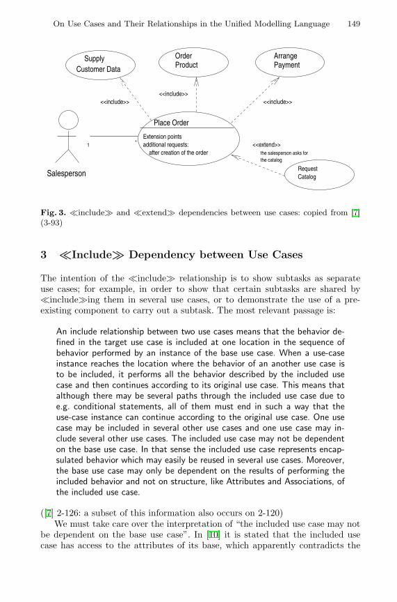
On Use Cases and Their Relationships in the Unified Modelling Language 149
SupplyCustomer Data
OrderProduct
ArrangePayment
Place Order
Extension pointsadditional requests: after creation of the order
RequestCatalog
<<extend>>
<<include>><<include>>
<<include>>
the salesperson asks for the catalog
1 *
Salesperson
Fig. 3. �include� and �extend� dependencies between use cases: copied from [7](3-93)
3 �Include� Dependency between Use Cases
The intention of the �include� relationship is to show subtasks as separateuse cases; for example, in order to show that certain subtasks are shared by�include�ing them in several use cases, or to demonstrate the use of a pre-existing component to carry out a subtask. The most relevant passage is:
An include relationship between two use cases means that the behavior de-fined in the target use case is included at one location in the sequence ofbehavior performed by an instance of the base use case. When a use-caseinstance reaches the location where the behavior of an another use case isto be included, it performs all the behavior described by the included usecase and then continues according to its original use case. This means thatalthough there may be several paths through the included use case due toe.g. conditional statements, all of them must end in such a way that theuse-case instance can continue according to the original use case. One usecase may be included in several other use cases and one use case may in-clude several other use cases. The included use case may not be dependenton the base use case. In that sense the included use case represents encap-sulated behavior which may easily be reused in several use cases. Moreover,the base use case may only be dependent on the results of performing theincluded behavior and not on structure, like Attributes and Associations, ofthe included use case.
([7] 2-126: a subset of this information also occurs on 2-120)We must take care over the interpretation of “the included use case may not
be dependent on the base use case”. In [10] it is stated that the included usecase has access to the attributes of its base, which apparently contradicts the
150 P. Stevens
lack of dependence; but indeed, it is not clear in what sense an included usecase can have a result if it is not allowed to affect the state of its parent! Weinterpret the lack of dependence as meaning simply that the included use casemakes sense, that is, is a valid use case, in its own right. Now as an included usecase can define its own attributes as well as having access to those of its parent,we conclude that its quotient map should induce a possibly finer equivalence onthe state of the entity and actors than its parent did.
Definition 5. A use case v = (S′, L′,→′, S′0) with quotient map hv is suitable
for inclusion in u = (S,L,→, S0) with quotient map hu if
1. hv is finer than hu; that is, hv(p) = hv(q) ⇒ hu(p) = hu(q);2. |hv(h−1
u (s)) ∩ S′0| ≤ 1 for all s ∈ S.
We write huv for the unique surjective map S′ → S such that huv ◦ hv = hu
In terms of attributes, condition 2 amounts to saying that if the included use casedefines a new attribute, then given values for the attributes already present inthe base use case there must be a single (“default”) value for the new attribute.This avoids the need to invent data for the extra attribute(s). If there are nonew attributes, that is, if hu = hv, the condition is vacuous.
We interpret the instruction that the base use case must depend only onthe result of the included use case as meaning that the base use case must bedescribable in terms which allow the substitution of any use case with the sameinduced PPC as the intended one. We restrict the circumstances under whichinclusion is allowed, for convenience and to reflect the intention that �include�(unlike �extend�) is used for unconditional, once-only inclusion of behaviour.Thus we define:
Definition 6. A use case u = (S,L,→, S0) with quotient map hu includes usecase v = (S′, L′,→′, S′
0) with quotient map hv via Source I→ Target if
1. v is suitable for inclusion in u;2. I ∈ L \ L′;3. Source, Target, S0 are pairwise disjoint subsets of S;4. hu(p) I→ hu(q) is a transition in u exactly when all of: (p, q) ∈ PP (v),
hu(p) ∈ Source, hu(q) ∈ Target hold;5. any element of sequences(u) includes at most one occurrence of I;6. the only transitions out of Source or into Target are those labelled I.
Such a use case depends only on the result of a suitable v, not on its details.To get a fully described use case including v itself we replace the source-targetgap by the actual behaviour of v, identifying source states with the appropriatestart states of v and target states with the appropriate final states; precisely:
On Use Cases and Their Relationships in the Unified Modelling Language 151
Definition 7. If u includes v via Source I→ Target then the composite use caseinclude(u, v, I) = (S′′, L′′,→′′, S′′
0 ) where
1. S′′ = S \ Source \ Target.∪ S′
2. L′′ = L \ {I} .∪ L′3. For s and t in S′′, s →′′ t iff one of the following holds:
– s → t in u (note that by insisting s, t are in S′′ we automatically discardtransitions to Source or from Target)
– s → s′ ∈ Source in u and t ∈ hv(h−1u (s′)) ∩ S′
0 (that is, t is a start stateof v corresponding to a source in u)
– t′ ∈ Target and t′ → t in u and t′ = huv(s) (that is, s is a final state ofv corresponding to a target in u)
– s →′ t in v4. S′′
0 = S0
The easy result that relates this process view to the trace inclusion viewfound in the standard is:
Lemma 2. If l1 . . . ln ∈ sequences(include(u, v, I)), then either
– l1 . . . ln ∈ sequences(u); or– for some 1 < m ≤ p ≤ n we have l1 . . . lmIlp . . . ln ∈ sequences(u) andlm+1 . . . lp−1 ∈ sequences(v).
2
We make no formal restriction on when the first case can occur, but to staywithin the spirit of the �include� relation this should indicate that somethingexceptional happened “before” the “inclusion point” of v. Because use cases areallowed to include exceptional or erroneous cases, in which the use case instancemight be “aborted” before v becomes relevant, it does not seem sensible to takeliterally the view that every trace of the composite use case should include atrace of v. One could make this artificially the case by writing v to include atrivial “not applicable” trace to be included at the end of any trace of u on whichv is never truly reached, but this seems pointless.
The �extend� relationship between use cases is similar; it is more complexbut raises no substantially new issues. For reasons of space we omit a detailedtreatment.
4 Generalisation of Use Cases
This is the most controversial of UML’s relationships between use cases. (Cock-burn writes, for example “In general, the problem with the generalizes relation isthat the professional community has not yet reached an understanding of whatit means to subtype and specialize behavior...” [4] p241.) The Notation Guidecontains no example of generalisation of use cases, and says only the “A gener-alization from use case A to use case B indicates that A is a specialization of B”(3-92). The example pictured above is taken from [10] and is typical of the waythe relationship is used: the idea is that the child use case should be a more fullydescribed version of its parent. The Semantics Guide appears more helpful:
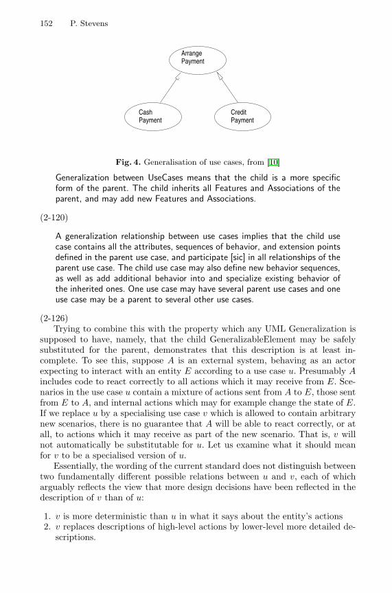
152 P. Stevens
ArrangePayment
CashPayment
CreditPayment
Fig. 4. Generalisation of use cases, from [10]
Generalization between UseCases means that the child is a more specificform of the parent. The child inherits all Features and Associations of theparent, and may add new Features and Associations.
(2-120)
A generalization relationship between use cases implies that the child usecase contains all the attributes, sequences of behavior, and extension pointsdefined in the parent use case, and participate [sic] in all relationships of theparent use case. The child use case may also define new behavior sequences,as well as add additional behavior into and specialize existing behavior ofthe inherited ones. One use case may have several parent use cases and oneuse case may be a parent to several other use cases.
(2-126)Trying to combine this with the property which any UML Generalization is
supposed to have, namely, that the child GeneralizableElement may be safelysubstituted for the parent, demonstrates that this description is at least in-complete. To see this, suppose A is an external system, behaving as an actorexpecting to interact with an entity E according to a use case u. Presumably Aincludes code to react correctly to all actions which it may receive from E. Sce-narios in the use case u contain a mixture of actions sent from A to E, those sentfrom E to A, and internal actions which may for example change the state of E.If we replace u by a specialising use case v which is allowed to contain arbitrarynew scenarios, there is no guarantee that A will be able to react correctly, or atall, to actions which it may receive as part of the new scenario. That is, v willnot automatically be substitutable for u. Let us examine what it should meanfor v to be a specialised version of u.
Essentially, the wording of the current standard does not distinguish betweentwo fundamentally different possible relations between u and v, each of whicharguably reflects the view that more design decisions have been reflected in thedescription of v than of u:
1. v is more deterministic than u in what it says about the entity’s actions2. v replaces descriptions of high-level actions by lower-level more detailed de-
scriptions.
On Use Cases and Their Relationships in the Unified Modelling Language 153
Each of these points requires further analysis. (2) is essentially what we didwith �include�, though a more flexible treatment would be useful. The mainthing to notice about (1) is that it only makes sense if we know which actionsare chosen by the entity and which by an actor. So far, we have not needed tomake such a distinction, and indeed we pointed out that it is sometimes desirableto describe use cases before such decisions have been taken. From the point ofview of an actor for whom v should be substitutable for u, it would be quitereasonable for v to include fewer transitions chosen by the entity, or indeed byother actors, but it would be unreasonable to include fewer transitions chosenby A. Again, A may have been coded to assume that it is permitted to take acertain transition, and might break if v forbade this. From a theoretical pointof view the most obviously appealing formalism to use to reflect this questionof where choices are made would be the alternating transition systems of [2];but as remarked before this conflicts with our desire to use minimal machinery– especially as we would need to do at least a little adaptation to deal withthe presence of more than the two choice-makers considered there. Perhaps thereactive module work of [1], might help. For now we adapt an approach dueto Jackson in [6], and say that from the point of view of a given actor A, theactions that make up a use case may be classified into inputs (actions initiatedby A affecting E), outputs (actions initiated by E affecting A) and all others(including internal actions by E and communications between E and actors otherthan A: recall that UML does not permit direct communication between actors,so this list is exhaustive). To what extent does an actor care about more thanits own input/output? It presumably does care about the PPC of the use case;after all, this is what specifies what the use case actually achieves. For simplicityin these early explorations, let us assume that u and v have identical label-setsand a bijection f from the start-states of v to the start-states of u.
From the point of view of an actor A who sees the actions of a use case uas FromMe
.∪ ToMe.∪ Other, write l⇒ for l→ preceded or followed by arbitrarily
many Other transitions. Then a candidate definition is:
Definition 8. v = (S′, L,→′, S′0) specialises u = (S,L,→, S0), iff the following
all hold:
– v satisfies PP (u)– there is some relation �⊆ S′ × S such that sv � su implies
– whenever i ∈ FromMe and sui⇒ s′
u is a transition in u, then there is a
transition sv
i
⇒′ s′v in v such that s′
v � s′u;
– whenever o ∈ ToMe and sv
o
⇒′ s′v is a transition in v, then there is a
transition suo⇒ s′
u in u such that s′v � s′
u;– s′
0 � f(s′0) for all s′
0 ∈ S′0.
A point that follows on from this is that if u involves several actors, which usecases v are specialisations of u depends on from which actor’s point of view wesee the relationship. What is the relation that results from insisting that v be aspecialisation from the point of view of all (beneficiary) actors? What difference
154 P. Stevens
does it make if actors are assumed capable of cooperation? Can these relationsbe put in a testing framework? Given appropriate high-level syntax, can theybe computed? We have abandoned the total correctness aspects of [6] (becausethe assumptions seem too strong for our context); can we recover somethinguseful when we want it? For these or some similar definitions, do �include�and generalisation interact cleanly, for example, is there some sense in which youcan be permitted to include a more specialised version of what you expected,and is the resulting composite use case a more specialised version of what youwould have had with the more general included use case? This may be too muchto hope.
5 Conclusions and Further Work
It is possible, and often pragmatically advisable, to use UML use cases in a com-pletely informal way, to describe the tasks to be carried out with the help of thesystem. Sometimes, however, we would like to have the option of relating usecases to the design of the system that implements them – or to that of anothersystem that uses them – in a soundly-based, tool-supportable way. Moreover, re-gardless of whether users of UML choose to describe their use cases in full detail,it seems reasonably to expect that the UML standard’s informal explanations ofwhat would be the case if one did, would be formalisable. In this paper we havebegun an attempt to provide, using the minimum of formal machinery, such aformalisation. It is surprising (at least to the author), given the modest scope ofthe present work, how much already has to be done. Directions of future workmight include, besides the answering of questions left open here:
High level formalisms for describing use cases. We have deliberately avoidedchoosing a high-level formalism for defining use cases, preferring to work at thebasic level of labelled transition systems or processes. These can for example bedefined using any process algebra or any kind of automata that has a labelledtransition system semantics; alternatively, they could be defined using (a suit-able formalisation of) statecharts. We suggest that it is probably impractical tostandardise on one such language within UML, at least at this point; were aformalisation of statecharts to be agreed in UML2.0, this would be an obviouscandidate, but others might be more appropriate in different circumstances. Itseems more appropriate to use the minimal notion of labelled transition systemin the UML standard.
Interference. We should consider interactions and interference between use caseinstances, both of the same use case and of different use cases. Pace [7]’s state-ment “This implies that after its performance the entity will in general be in a statein which the sequence can be initiated again.”, ordering dependencies between usecases often exist and are sometimes modelled with activity diagrams; how canthis be formalised? What is the relationship between the set of all use casesand the entity itself? [7] (2-124) says “The complete set of use cases specifies alldifferent ways to use the entity, i.e. all behaviour of the entity is expressed by its usecases.”; in what formal sense can this be true?
On Use Cases and Their Relationships in the Unified Modelling Language 155
Acknowledgements. I am grateful to the British Engineering and PhysicalSciences Research Council for funding in the form of an Advanced ResearchFellowship, and also to the referees for constructive comments.
References
[1] Rajeev Alur and Thomas A. Henzinger. Reactive modules. Formal Methods inSystem Design, 15:7–48, 1999.
[2] Rajeev Alur, Thomas A. Henzinger, Orna Kupferman, , and Moshe Y. Vardi.Alternating refinement relations. In Proceedings of the Ninth International Con-ference on Concurrency Theory (CONCUR 1998), number 1466 in LNCS, pages163–178. Springer-Verlag, 1998.
[3] C. Bolton and J. Davies. Activity graphs and processes. In Proceedings of IFM2000, 2000.
[4] Alistair Cockburn. Writing Effective Use Cases. Addison-Wesley, 2001.[5] Desmond D’Souza and Alan Cameron Wills. Catalysis: Objects, Frameworks and
Components in UML. Addison-Wesley, 1998.[6] Paul B. Jackson. Total correctness refinement for sequential reactive systems. In
proceedings of TPHOLs 2000. (13th International Conference on Theorem Provingin Higher Order Logics), number 1869 in LNCS, pages 320–337. Springer-Verlag,August 2000.
[7] OMG. Unified Modeling Language Specification version 1.3, June 1999. OMGdocument 99-06-08 available from www.omg.org.
[8] G. Overgaard and K. Palmkvist. A Formal Approach to Use cases and theirRelationships. In P.-A. Muller and J. Bezivin, editors, Proceedings of �UML�’98:Beyond the Notation, pages 309–317. Ecole Superieure des Sciences Appliqueespour l’Ingenieur – Mulhouse, Universite de Haut-Alsace, France, June 1998.
[9] Gunnar Overgaard. Formal Specification of Object-Oriented Modelling Concepts.PhD thesis, Department of Teleinformatics, Royal Institute of Technology, Stock-holm, Sweden, 2000.
[10] James Rumbaugh, Ivar Jacobson, and Grady Booch. The Unified Modeling Lan-guage Reference Manual. Addison Wesley, 1998.
H. Hussmann (Ed.): FASE 2001, LNCS 2029, pp. 156-170, 2001.© Springer-Verlag Berlin Heidelberg 2001
On the Importance of Inter-scenarioRelationships in Hierarchical State Machine
Design
Francis Bordeleau and Jean-Pierre Corriveau
School of Computer Science, Carleton University, Ottawa, Canada{francis, jeanpier}@scs.carleton.ca
Abstract. One of the most crucial and complicated phases of systemdevelopment lies in the transition from system behavior (generally specifiedusing scenario models) to the detailed behavior of the interacting components(typically captured by means of communicating hierarchical finite statemachines). This transition constitutes the focus of this paper. Our standpoint isthat in order to succeed with this transition, it is not sufficient to grasp thedetails of individual scenarios, but also to understand the relationships that existbetween the scenarios. Our claim is that different types of scenario relationshipsresult in different hierarchical state machine structures. We identify and describefour different types of scenario relationships: containment dependency,alternative dependency, temporal dependency, and functional dependency. Wealso illustrate how such scenario relationships can be expressed in UML usingstereotypes and how they guide the design of the corresponding hierarchicalstate machines.
1 Introduction
In current object-oriented modeling methodologies [1,2], systems are generallymodeled using three apparently orthogonal ‘views’ namely: structure, behavior, andinteractions. Semantically, however, these three views overlap considerably [3,4].That is, they present much of the same conceptual information from differentperspectives and with varying levels of detail. In particular, the behavioral viewexpresses the complete behavior of each component (or class) of a system in terms ofstates and transitions, typically organized into hierarchical state machines [5].Conversely, the interactions view captures how system requirements map ontosequences of responsibilities to be executed by components [3,4,6]. Such sequencesare generally referred to as scenarios. In UML, such scenarios can be captured atdifferent levels of abstraction using use cases, activity diagrams, sequence diagrams,and collaboration diagrams [7]. In our terminology, we use the term scenario to referto one of the different paths of execution captured within a single use case. That is,each scenario forms a specific sequence of responsibilities. We argue in section 2 forthe importance of a scenario-driven, as opposed to a use case-driven approach to thedesign of component behavior.
In a scenario-driven approach to object-oriented modeling [e.g., 8], thescenarios of a system constitute the foundation for the design of the completebehavior of the individual components of this system. That is, whereas each scenarioillustrates the behavior of (one or more instances of) a component (viz. class) in aspecific context, the state machine associated with this component captures the
On the Importance of Inter-scenario Relationships 157
behavior of that component across all the contexts to which (instances of) itparticipates. We consider the transition needed to go from scenario models tocommunicating hierarchical state machine models to be one of the most crucial andcomplex steps of object-oriented system design. Factors that contribute to thecomplexity of this transition include:� Large number of scenarios. Typical object-oriented systems are composed of
very large sets of scenarios, and each component is usually involved in theexecution of many different scenarios. A component’s behavior needs to handleeach of the scenarios in which this component is involved.
� Concurrency and interactions between scenarios. This point follows from theprevious one. Scenarios can be concurrent and may interact with each other (e.g.,one aborts another or is an alternative to it). This is an aspect of object-orientedsystems that makes them particularly complex and difficult to design. Morespecifically, it is not sufficient to address only the temporal ordering of scenarios.In fact, it is their functional (or equivalently, logical) ordering, and in particulartheir causal ordering, that must be taken into account in the specification ofcomponent behaviors.
� Scenarios of different types. Object-oriented systems generally implementscenarios of different types. For example, one may categorize scenarios into thosethat tackle normal executions (‘primary’ scenarios), and those that capturealternatives (‘secondary’ scenarios). Another categorization scheme may focus onthe functional aspects of scenarios: control, configuration, service interruption,failure, error recovery, maintenance, etc. Identifying such scenario types mayimpact on the structuring of component behavior.
� Maintainability and extensibility of components. Since most industrial systemshave a long lifecycle, it is very important to build system components so that theycan be easily maintained and extended. Thus, it is not sufficient to definecomponent behaviors that satisfy the current requirements. It is also desirable todefine them so that they facilitate future modifications. Indeed, we contend that thestructuring of the behavior of a component is one of the most important factorscontributing to component maintainability and extensibility. This constitutes animportant nonfunctional requirement that must be considered by designers.
The transition between scenario models and hierarchical state machines constitutesthe focus of our work [4,9]. Our standpoint is that in order to successfully proceedfrom scenarios to state machines, it is not sufficient to grasp the details of individualscenarios, but also to understand the relationships that exist between these scenarios.We believe that understanding the relationships that exist between a set of scenariosthat are to be implemented in a communicating hierarchical state machine model isone of the fundamentals steps in the design of complex object-oriented systems.
Our thesis is that different types of scenario relationships result in differenthierarchical state machine structures [Ibid.]. More precisely, for a component x, thesemantic relationship between two scenarios S1 and S2 to which x participates shouldguide the designer in integrating the behavior associated with x in S1 with thebehavior of x in S2. Indeed, we have proposed elsewhere [Ibid.] a hierarchy ofbehavior integration patterns used to provide a systematic approach to the transitionfrom scenarios to hierarchical state machines.
In this paper, we sketch out the scenario relationships at the basis of thesepatterns. We first summarize, in section 2, our pattern-based approach to the transition
158 F. Bordeleau and J.-P. Corriveau
from scenarios to state machines. We then introduce, in section 3, a simple exampleused to illustrate the scenario relationships from which this transition proceeds. Eachof these relationships is defined and overviewed in section 4. We review other relatedapproaches in section 5 and discuss the issue of automation. We conclude with a briefdiscussion of some of the advantages of our approach.
2 Proposed Approach
In order to design the (possibly hierarchical) state machine of a complex component,the modeling strategy we propose draws on both the relationships and details ofscenarios. The exact notation used for the specification of scenarios (e.g., messagesequence charts (MSCs) [10], sequence diagrams [1,7]) does not play a significantrole in the use of our integration patterns. However, we remark that, except for UseCase Maps (UCMs) [4,6], few notations explicitly capture inter-scenariorelationships. And yet we have found that such explicit relationships do simplify theapplication of the integration patterns we suggest.
Our thesis, we repeat, is that, for some component x, the integration of a newscenario S1 (in which x participates) into the existing state machine f of x mustdepend on the pair-wise relationships existing between S1 and the scenarios alreadyhandled by f. This aspect of our work will be discussed in section 4. For now, wewant to summarize the overall approach we are proposing for going from scenarios tostate machines. This approach, summarized in Figure 1, consists of three steps:
First, the designer must capture scenarios and their inter-relationships. Recallthat a use case may capture a multitude of different scenarios, that is, a multitude ofdifferent paths of execution. Thus, a relationship between two use cases expresses asemantic dependency between sets of scenarios, rather than between specificscenarios. Our thesis is that specific inter-scenario relationships play a major role inthe design of the hierarchical state machines of the components involved in thesescenarios. The exact nature of these relationships is of little import in most existingUML-based modeling processes. In contrast, in the first step of our approach, we arerecommending that a designer start by identifying the pair-wise relationships betweenscenarios. From our standpoint, the exact classification of these relationships is notessential to the application of our strategy; only that each inter-scenario relationshiphas a specific impact on the design of the state machines associated with the relevantscenario components. In other words, the set of inter-scenario relationships introducedin section 4 is not to be taken as sufficient or complete, but merely as representative.Indeed, we will briefly demonstrate, in that section, that each of the four inter-scenario relationships we put forth has a direct impact on the organization of the statemachines of the relevant components.
In UML, scenarios are first captured by means of use cases. The latter are notmeant to exist in complete independence from one another: a use case diagram is tocapture their relationships, which take the form of unidirectional associations. User-defined stereotypes can be specified for these associations (as for any associations inUML). UML currently proposes four built-in stereotypes [1,7] for use cases, none fortheir relationships. Moreover, use case relationships are not our primary concern.Instead, we focus firstly on scenario relationships. But use case and scenariorelationships clearly overlap semantically.
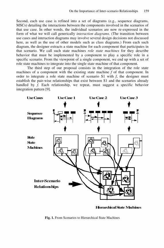
On the Importance of Inter-scenario Relationships 159
Second, each use case is refined into a set of diagrams (e.g., sequence diagrams,MSCs) detailing the interactions between the components involved in the scenarios ofthat use case. In other words, the individual scenarios are now re-expressed in theform of what we will call generically interaction diagrams. (The transition betweenuse cases and interaction diagrams may involve several design decisions not discussedhere, as well as the use of other models such as class diagrams.) From each suchdiagram, the designer extracts a state machine for each component that participates inthat scenario. We call such state machines role state machines for they describebehavior that must be implemented by a component to play a specific role in aspecific scenario. From the viewpoint of a single component, we end up with a set ofrole state machines to integrate into the single state machine of that component.
The third step of our proposal consists in the integration of the role statemachines of a component with the existing state machine f of that component. Inorder to integrate a role state machine of scenario S1 with f, the designer mustestablish the pair-wise relationships that exist between S1 and the scenarios alreadyhandled by f. Each relationship, we repeat, must suggest a specific behaviorintegration pattern [9].
Hierarchical State Machines
Role
SequenceDiagrams
State
Machines
Inter-Scenario
Relationships
Use Cases Use Case 2Use Case 1 Use Case 3
Fig. 1. From Scenarios to Hierarchical State Machines
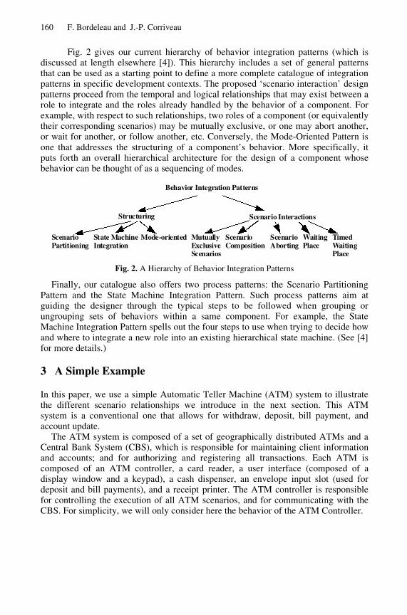
160 F. Bordeleau and J.-P. Corriveau
Fig. 2 gives our current hierarchy of behavior integration patterns (which isdiscussed at length elsewhere [4]). This hierarchy includes a set of general patternsthat can be used as a starting point to define a more complete catalogue of integrationpatterns in specific development contexts. The proposed ‘scenario interaction’ designpatterns proceed from the temporal and logical relationships that may exist between arole to integrate and the roles already handled by the behavior of a component. Forexample, with respect to such relationships, two roles of a component (or equivalentlytheir corresponding scenarios) may be mutually exclusive, or one may abort another,or wait for another, or follow another, etc. Conversely, the Mode-Oriented Pattern isone that addresses the structuring of a component’s behavior. More specifically, itputs forth an overall hierarchical architecture for the design of a component whosebehavior can be thought of as a sequencing of modes.
Behavior Integration Patterns
Structuring Scenario Interactions
Scenario Partitioning
Mode-oriented MutuallyExclusiveScenarios
State MachineIntegration
ScenarioComposition
ScenarioAborting
WaitingPlace
TimedWaitingPlace
Fig. 2. A Hierarchy of Behavior Integration Patterns
Finally, our catalogue also offers two process patterns: the Scenario PartitioningPattern and the State Machine Integration Pattern. Such process patterns aim atguiding the designer through the typical steps to be followed when grouping orungrouping sets of behaviors within a same component. For example, the StateMachine Integration Pattern spells out the four steps to use when trying to decide howand where to integrate a new role into an existing hierarchical state machine. (See [4]for more details.)
3 A Simple Example
In this paper, we use a simple Automatic Teller Machine (ATM) system to illustratethe different scenario relationships we introduce in the next section. This ATMsystem is a conventional one that allows for withdraw, deposit, bill payment, andaccount update.
The ATM system is composed of a set of geographically distributed ATMs and aCentral Bank System (CBS), which is responsible for maintaining client informationand accounts; and for authorizing and registering all transactions. Each ATM iscomposed of an ATM controller, a card reader, a user interface (composed of adisplay window and a keypad), a cash dispenser, an envelope input slot (used fordeposit and bill payments), and a receipt printer. The ATM controller is responsiblefor controlling the execution of all ATM scenarios, and for communicating with theCBS. For simplicity, we will only consider here the behavior of the ATM Controller.
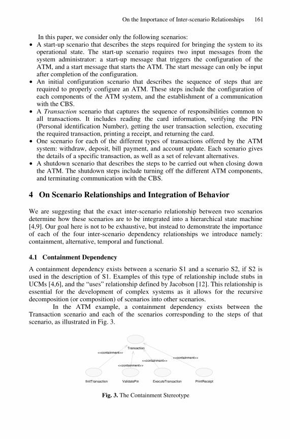
On the Importance of Inter-scenario Relationships 161
In this paper, we consider only the following scenarios:� A start-up scenario that describes the steps required for bringing the system to its
operational state. The start-up scenario requires two input messages from thesystem administrator: a start-up message that triggers the configuration of theATM, and a start message that starts the ATM. The start message can only be inputafter completion of the configuration.
� An initial configuration scenario that describes the sequence of steps that arerequired to properly configure an ATM. These steps include the configuration ofeach components of the ATM system, and the establishment of a communicationwith the CBS.
� A Transaction scenario that captures the sequence of responsibilities common toall transactions. It includes reading the card information, verifying the PIN(Personal identification Number), getting the user transaction selection, executingthe required transaction, printing a receipt, and returning the card.
� One scenario for each of the different types of transactions offered by the ATMsystem: withdraw, deposit, bill payment, and account update. Each scenario givesthe details of a specific transaction, as well as a set of relevant alternatives.
� A shutdown scenario that describes the steps to be carried out when closing downthe ATM. The shutdown steps include turning off the different ATM components,and terminating communication with the CBS.
4 On Scenario Relationships and Integration of Behavior
We are suggesting that the exact inter-scenario relationship between two scenariosdetermine how these scenarios are to be integrated into a hierarchical state machine[4,9]. Our goal here is not to be exhaustive, but instead to demonstrate the importanceof each of the four inter-scenario dependency relationships we introduce namely:containment, alternative, temporal and functional.
4.1 Containment Dependency
A containment dependency exists between a scenario S1 and a scenario S2, if S2 isused in the description of S1. Examples of this type of relationship include stubs inUCMs [4,6], and the “uses” relationship defined by Jacobson [12]. This relationship isessential for the development of complex systems as it allows for the recursivedecomposition (or composition) of scenarios into other scenarios.
In the ATM example, a containment dependency exists between theTransaction scenario and each of the scenarios corresponding to the steps of thatscenario, as illustrated in Fig. 3.
Fig. 3. The Containment Stereotype
IInitTransaction ValidatePin ExecuteTransaction PrintReceipt
Transaction <<containment>>
<<containment>> <<containment>>
<<containment>>
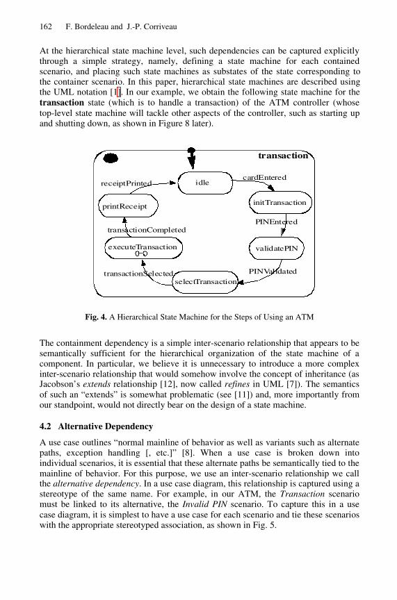
162 F. Bordeleau and J.-P. Corriveau
At the hierarchical state machine level, such dependencies can be captured explicitlythrough a simple strategy, namely, defining a state machine for each containedscenario, and placing such state machines as substates of the state corresponding tothe container scenario. In this paper, hierarchical state machines are described usingthe UML notation [1]. In our example, we obtain the following state machine for thetransaction state (which is to handle a transaction) of the ATM controller (whosetop-level state machine will tackle other aspects of the controller, such as starting upand shutting down, as shown in Figure 8 later).
validatePIN
idle
selectTransaction
transactionI
initTransaction
executeTransaction
printReceipt
transactionSelected PINValidated
PINEntered
cardEntered
transactionCompleted
receiptPrinted
Fig. 4. A Hierarchical State Machine for the Steps of Using an ATM
The containment dependency is a simple inter-scenario relationship that appears to besemantically sufficient for the hierarchical organization of the state machine of acomponent. In particular, we believe it is unnecessary to introduce a more complexinter-scenario relationship that would somehow involve the concept of inheritance (asJacobson’s extends relationship [12], now called refines in UML [7]). The semanticsof such an “extends” is somewhat problematic (see [11]) and, more importantly fromour standpoint, would not directly bear on the design of a state machine.
4.2 Alternative Dependency
A use case outlines “normal mainline of behavior as well as variants such as alternatepaths, exception handling [, etc.]” [8]. When a use case is broken down intoindividual scenarios, it is essential that these alternate paths be semantically tied to themainline of behavior. For this purpose, we use an inter-scenario relationship we callthe alternative dependency. In a use case diagram, this relationship is captured using astereotype of the same name. For example, in our ATM, the Transaction scenariomust be linked to its alternative, the Invalid PIN scenario. To capture this in a usecase diagram, it is simplest to have a use case for each scenario and tie these scenarioswith the appropriate stereotyped association, as shown in Fig. 5.
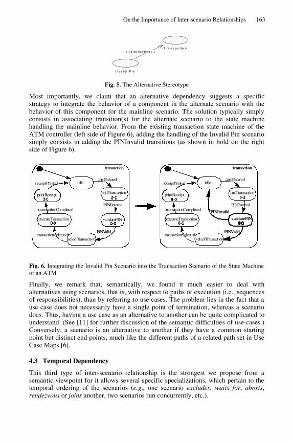
On the Importance of Inter-scenario Relationships 163
In va li d P i n
T ra n s a c t i o n< < a lte r n a t i v e > >
Fig. 5. The Alternative Stereotype
Most importantly, we claim that an alternative dependency suggests a specificstrategy to integrate the behavior of a component in the alternate scenario with thebehavior of this component for the mainline scenario. The solution typically simplyconsists in associating transition(s) for the alternate scenario to the state machinehandling the mainline behavior. From the existing transaction state machine of theATM controller (left side of Figure 6), adding the handling of the Invalid Pin scenariosimply consists in adding the PINInvalid transitions (as shown in bold on the rightside of Figure 6).
validatePIN
idle
selectTransaction
transactionI
initTransaction
executeTransaction
printReceipt
transactionSelectedPINValid
PINEntered
cardEntered
transactionCompleted
receiptPrinted
PINInvalid
validatePIN
idle
selectTransaction
transactionI
initTransaction
executeTransaction
printReceipt
transactionSelectedPINValid
PINEntered
cardEntered
transactionCompleted
receiptPrinted
Fig. 6. Integrating the Invalid Pin Scenario into the Transaction Scenario of the State Machineof an ATM
Finally, we remark that, semantically, we found it much easier to deal withalternatives using scenarios, that is, with respect to paths of execution (i.e., sequencesof responsibilities), than by referring to use cases. The problem lies in the fact that ause case does not necessarily have a single point of termination, whereas a scenariodoes. Thus, having a use case as an alternative to another can be quite complicated tounderstand. (See [11] for further discussion of the semantic difficulties of use-cases.)Conversely, a scenario is an alternative to another if they have a common startingpoint but distinct end points, much like the different paths of a related path set in UseCase Maps [6].
4.3 Temporal Dependency
This third type of inter-scenario relationship is the strongest we propose from asemantic viewpoint for it allows several specific specializations, which pertain to thetemporal ordering of the scenarios (e.g., one scenario excludes, waits for, aborts,rendezvous or joins another, two scenarios run concurrently, etc.).
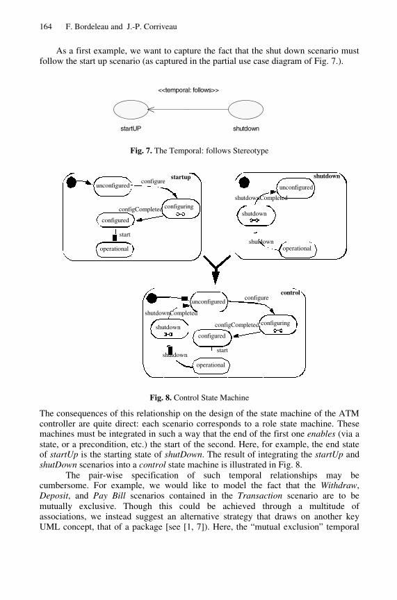
164 F. Bordeleau and J.-P. Corriveau
As a first example, we want to capture the fact that the shut down scenario mustfollow the start up scenario (as captured in the partial use case diagram of Fig. 7.).
Fig. 7. The Temporal: follows Stereotype
configuring configCompleted
unconfigured
operational
control I
shutdown
shutdown
configure
configured start
configuring configCompleted
unconfigured
operational
startup I configure
start
unconfigured
operational
shutdown I
shutdown
shutdown
shutdownCompleted
configured
shutdownCompleted
Fig. 8. Control State Machine
The consequences of this relationship on the design of the state machine of the ATMcontroller are quite direct: each scenario corresponds to a role state machine. Thesemachines must be integrated in such a way that the end of the first one enables (via astate, or a precondition, etc.) the start of the second. Here, for example, the end stateof startUp is the starting state of shutDown. The result of integrating the startUp andshutDown scenarios into a control state machine is illustrated in Fig. 8.
The pair-wise specification of such temporal relationships may becumbersome. For example, we would like to model the fact that the Withdraw,Deposit, and Pay Bill scenarios contained in the Transaction scenario are to bemutually exclusive. Though this could be achieved through a multitude ofassociations, we instead suggest an alternative strategy that draws on another keyUML concept, that of a package [see [1, 7]). Here, the “mutual exclusion” temporal
shutdownstartUP
<<temporal: follows>>
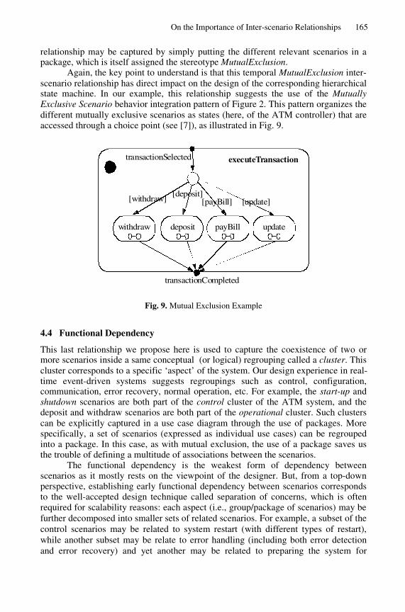
On the Importance of Inter-scenario Relationships 165
relationship may be captured by simply putting the different relevant scenarios in apackage, which is itself assigned the stereotype MutualExclusion.
Again, the key point to understand is that this temporal MutualExclusion inter-scenario relationship has direct impact on the design of the corresponding hierarchicalstate machine. In our example, this relationship suggests the use of the MutuallyExclusive Scenario behavior integration pattern of Figure 2. This pattern organizes thedifferent mutually exclusive scenarios as states (here, of the ATM controller) that areaccessed through a choice point (see [7]), as illustrated in Fig. 9.
executeTransactionI
withdraw updatepayBilldeposit
[withdraw][deposit]
[payBill] [update]
transactionSelected
transactionCompleted
Fig. 9. Mutual Exclusion Example
4.4 Functional Dependency
This last relationship we propose here is used to capture the coexistence of two ormore scenarios inside a same conceptual (or logical) regrouping called a cluster. Thiscluster corresponds to a specific ‘aspect’ of the system. Our design experience in real-time event-driven systems suggests regroupings such as control, configuration,communication, error recovery, normal operation, etc. For example, the start-up andshutdown scenarios are both part of the control cluster of the ATM system, and thedeposit and withdraw scenarios are both part of the operational cluster. Such clusterscan be explicitly captured in a use case diagram through the use of packages. Morespecifically, a set of scenarios (expressed as individual use cases) can be regroupedinto a package. In this case, as with mutual exclusion, the use of a package saves usthe trouble of defining a multitude of associations between the scenarios.
The functional dependency is the weakest form of dependency betweenscenarios as it mostly rests on the viewpoint of the designer. But, from a top-downperspective, establishing early functional dependency between scenarios correspondsto the well-accepted design technique called separation of concerns, which is oftenrequired for scalability reasons: each aspect (i.e., group/package of scenarios) may befurther decomposed into smaller sets of related scenarios. For example, a subset of thecontrol scenarios may be related to system restart (with different types of restart),while another subset may be relate to error handling (including both error detectionand error recovery) and yet another may be related to preparing the system for
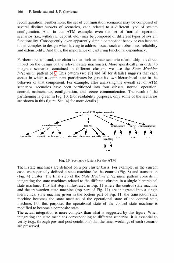
166 F. Bordeleau and J.-P. Corriveau
reconfiguration. Furthermore, the set of configuration scenarios may be composed ofseveral distinct subsets of scenarios, each related to a different type of systemconfiguration. And, in our ATM example, even the set of ‘normal’ operationscenarios (i.e., withdraw, deposit, etc.) may be composed of different types of systemfunctionality. Consequently, even apparently simple component behavior can becomerather complex to design when having to address issues such as robustness, reliabilityand extensibility. And thus, the importance of capturing functional dependency.
Furthermore, as usual, our claim is that such an inter-scenario relationship has directimpact on the design of the relevant state machine(s). More specifically, in order tointegrate scenarios contained in different clusters, we use the State MachineIntegration pattern of 0. This pattern (see [9] and [4] for details) suggests that eachaspect in which a component participates be given its own hierarchical state in thebehavior of that component. For example, after analyzing the overall set of ATMscenarios, scenarios have been partitioned into four subsets: normal operation,control, maintenance, configuration, and secure communication. The result of thepartitioning is given in Fig. 10. (For readability purposes, only some of the scenariosare shown in this figure. See [4] for more details.)
overall set of ATM system scenarios
normal operation control
transaction deposit withdraw ... start-up reconfig
maintenance config
...shutdown errorhandling
...
communication
......
Fig. 10. Scenario clusters for the ATM
Then, state machines are defined on a per cluster basis. For example, in the currentcase, we separately defined a state machine for the control (Fig. 8) and transaction(Fig. 4) cluster. The final step of the State Machine Integration pattern consists inintegrating the state machines related to the different clusters in a single hierarchicalstate machine. This last step is illustrated in Fig. 11 where the control state machineand the transaction state machine (top part of Fig. 11) are integrated into a singlehierarchical state machine given in the bottom part of Fig. 11: the transaction statemachine becomes the state machine of the operational state of the control statemachine. For this purpose, the operational state of the control state machine ismodified to become a composite state.The actual integration is more complex than what is suggested by this figure. Whenintegrating the state machines corresponding to different scenarios, it is essential toverify (e.g., through pre- and post-conditions) that the inner workings of each scenarioare preserved.
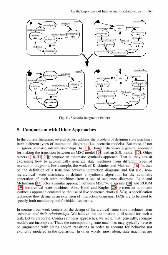
On the Importance of Inter-scenario Relationships 167
configuringconfigCompleted
unconfigured
ope rational
c ontrolI
shutdown
shutdown
configure
configured
start
shutdownCompleted
configuringconfigCompleted
unconfigured
operational
control
shutdown
shutdown
configure
configured
start
shutdownCompleted
validatePIN
idle
selectTransaction
operationalI
initTransaction
executeTransaction
printReceipt
transactionSelectedPINValid
PINEntered
cardEntered
transactionCompleted
receiptPrinted
PINInvalid
validatePIN
idle
selectTransaction
transactionI
initTransaction
executeTransaction
printReceipt
transactionSelectedPINValid
PINEntered
cardEntered
transactionCompleted
receiptPrinted
PINInvalid
Fig. 11. Scenario Integration Pattern
5 Comparison with Other Approaches
In the current literature, several papers address the problem of defining state machinesfrom different types of interaction diagrams (i.e., scenario models). But most, if notal, ignore scenario inter-relationships. In [13], Haugen discusses a general approachfor making the transition between an MSC model [14] and an SDL model [15]. Otherpapers ([16, 17, 20]) propose an automatic synthesis approach. That is, they aim atexplaining how to automatically generate state machines from different types ofinteraction diagrams. For example, the work of Koskimies and Makinen [16] focuseson the definition of a transition between interaction diagrams and flat (i.e., non-hierarchical) state machines. It defines a synthesis algorithm for the automaticgeneration of such state machines from a set of sequence diagrams. Leue andMehrmann [17] offer a similar approach between MSC’96 diagrams [18] and ROOM[19] hierarchical state machines. Also, Harel and Kugler [20] present an automaticsynthesis approach centered on the use of live sequence charts (LSCs), a specificationtechnique they define as an extension of interaction diagrams. LCSs are to be used tospecify both mandatory and forbidden scenarios.
In contrast, our work centers on the design of hierarchical finite state machines fromscenarios and their relationships. We believe that automation is ill-suited for such atask. Let us elaborate. Contra synthesis approaches, we recall that, generally, scenariomodels are incomplete. Thus, the corresponding state machines may typically have tobe augmented with states and/or transitions in order to account for behavior notexplicitly modeled in the scenarios. In other words, most often, state machines are
168 F. Bordeleau and J.-P. Corriveau
not semantically equivalent to the scenarios from which they proceed, but in factconstitute ‘semantic extensions’ to these scenarios. But the very nature of statemachines makes them difficult to modify: for example, one new transition maygenerate indeterminism. Thus, we repeat, it is essential to immediately structurecomponent behavior for extensibility. And, in our opinion, this is not achieved insynthesis approaches. That is, we believe that an automatically generated statemachine is seldom ‘semantically customizable’. This is especially true for flat statemachines.
The generation of a flat state machine from some algorithm is undoubtedlyuseful for activities such as validation and verification. However, we find it absolutelycrucial to use hierarchical state machines for designing components: hierarchical statemachines not only enable iterative development of the behavior of a component, butalso promote its understandability, testability and scalability. Whereas a flat statemachine, regardless of its number of states, is suitable for exhaustive path analysis,hierarchical state machines allow for the clustering of different behavioral facets of acomponent (often referred to as roles) into distinct hierarchical states of thiscomponent. Such a separation of concern is required for the understanding of complexbehavior, and for its evolution, two essential characteristics of a good design. Putanother way, we need hierarchical states to decouple clusters of states from each otherin order to i) understand their corresponding roles and ii) ease the evolution of eachsuch role (in particular with respect to behavior not explicitly captured in scenariomodels).
Subsuming this argumentation, we find our conviction that component designis an act of creation guided by a multitude of decisions typically lost in the automaticgeneration of a (typically flat) state machine from some other (often incomplete)model or specification.
The idea of patterns ([22, 23, 24]) has been put forth in several subfields ofsoftware engineering (e.g., analysis, architecture, design, testing) as a means todocument typical sets of decisions. Work on behavioral patterns (e.g., Gamma et al.[23]) has mostly focus on inter-component behavior. Indeed, few researchers havefocused on patterns for the design of the behavior of a component. Douglass's workon dynamic modeling (chapter 12 of [25]) is a noticeable exception: he is concernedwith “useful ways to structure states rather than objects” (Ibid., p.588). And he clearlyadvocates hierarchical state machines to do this: “many of the state patterns useorthogonal components to separate out independent aspects of the state machine.”(Ibid., p.589).
The 18 state behavior patterns put forth by Douglass form a catalogue oftypical behaviors for a component. Let us consider, for example, the Polling StatePattern. “Many problems require active, periodic data acquisition. The objectprocessing this data often has states associated with the problem semantics that areunrelated to the acquisition of data... The Polling State Pattern solves this problem byorganizing the state machine into two distinct orthogonal components. The firstacquires the data periodically. The second component manages the object state... Thisallows data handling to scale up to more complex state behavior.” (Ibid., p.593).
Such a description, and in particular the need for hierarchical states and the goal ofconventionalizing behavior, emphasizes the closeness of Douglass's work to ours. Butthere is a significant difference between our approaches: his catalogue of patternsproceeds from his identification of a set of typical behaviors (viz., detailed roles)
On the Importance of Inter-scenario Relationships 169
often encountered in components of object-oriented systems (e.g., polling, waitingrendezvous, balking rendezvous, timed rendezvous, random state, etc.). In contrast,we do not try to catalogue typical behaviors of a component but insteadconventionalize the transition from scenarios to hierarchical state machines. Moreprecisely, we start with a set of scenarios that express (albeit perhaps partlyimplicitly) the behavior of their components. We do not assume that the behavior of acomponent is necessarily typical, that is, that it matches a specific detailed role.Instead, we assemble the behavior of a component from the scenarios in which it isused, leaving room for the combination of detailed roles within a same component, aswell as for semantic customization. Furthermore, our approach is iterative: we do notrequire that all relevant scenarios be known before starting to design the behavior of acomponent. Instead, new roles can be progressively integrated into the behavior of anexisting component.
6 Conclusions
In this paper, we have presented a three-step approach to a systematic transition fromscenarios to hierarchical state machines. This approach rests on the definition of inter-scenario relationships (such as containment, alternative, temporal and functionaldependency) and of the corresponding families of behavior integration patterns, whichwe have very briefly introduced but discuss at length elsewhere ([4]).
We are currently working on formalizing scenario temporal and functionaldependency. For the former, existing work on temporal logic and notations such asLOTOS [25] serves as a starting point. Our goal is to focus on temporal expressionsthat have direct impact on state machine design. Similarly, for functional dependency,existing work on causal relationships (in particular in Artificial Intelligence) isscrutinized in order to find forms that bear on state machine design.
Industrial experience with the approach we propose suggests the following benefits:� Reducing the time required to design complex component behavior� Increasing the quality of the design of complex component behavior� Reducing the time required to test complex component behavior� Reducing undesired scenario interactions� Increasing traceability between scenarios and detailed component behavior
To conclude, let us remark that the approach described in this paper is constantlyevolving as a result of its use in industry, as well as in academia. In particular, ourmethod is followed by the Versatel group of CML Technologies, as well as by oursoftware engineering students at Carleton University. It is also at the basis of a recentuniversity-industry NSERC funding initiative with Nortel Networks to define astandard development process in the context of the Wireless Intelligent Networkss(WIN) standard definition.
References
1. Object Management Group: OMG Unified Modeling Language Specification.2. Henderson-Sellers, B. and Firesmith, D.: The Open Modeling Language Reference
Manual, Cambridge University Press, 1998.
170 F. Bordeleau and J.-P. Corriveau
3. Corriveau, J.-P.: Traceability and Process for Large OO projects, IEEE Computer, pp. 63-68, 1996 (also available in a longer version in: Technology of Object-Oriented Languagesand Systems (TOOLS-USA-96), Santa-Barbara, August 1996.
4. Bordeleau, F.: A Systematic and Traceable Progression from Scenario Models toCommunicating Hierarchical State Machines. Ph.D. Thesis, Department of Systems andComputer Engineering, Carleton University, Ottawa, Canada, 1999. (Available athttp//www.scs.carleton.ca/~francis)
5. Harel, D.: StateCharts: A Visual Formalism for Complex Systems, Science of ComputerProgramming, Vol. 8, pp. 231-274, 1987.
6. Buhr, R. J. A. and Casselman R. S.: Use Case Maps for Object-Oriented Systems, PrenticeHall, 1996.
7. Rumbaugh, J., Jacobson, I., Booch, G.: The Unified Modeling Language ReferenceManual, Addison-Wesley, 1999.
8. Kruchten, P.: The Rational Unified Process: An Introduction, Addison-Wesley, 1999.9. Bordeleau, F., Corriveau, J.-P., Selic, B.: A Scenario-Based Approach for Hierarchical
State Machine Design, Proceedings of the 3rd IEEE International Symposium on Object-Oriented Real-time Distributed Computing (ISORC’2000), Newport Beach, California,March 15 - 17, 2000.
10. ITU (1996) : Message Sequence Charts (MSC’96), Recommendation Z.120, Geneva.11. Firesmith, D.: The Pros and Cons of Use Cases, ROAD, May 1996.12. Jacobson, I. et al.: Object Oriented Software Engineering, Addison-Wesley, 1994.13. Haugen, O.: MSC Methodology, SISU II Report L-1313-7, Oslo, Norway, 1994.14. ITU (1993) : Message Sequence Charts (MSC’93). Recommendation Z.120, Geneva.15. ITU (1992): Specification and Description Language (SDL’92), Recommendation Z.100,
Geneva.16. Koskimies, K., Makinen, E.: Automatic Synthesis of State Machines from Trace
Diagrams, Software-Practice and Experience, vol. 24, No. 7, pp. 643-658 (July 1994).17. Leue, S., Mehrmann, L., Rezai M.: Synthesizing ROOM Models From Message Sequence
Charts Specifications, TR98-06, Department of Electrical and Computer Engineering,University of Waterloo, Waterloo, Canada, 1998.
18. ITU (1996) : Message Sequence Charts (’96), Recommendation Z.120, Geneva.19. Selic, B., Gullickson, G., and Ward, P.T.: Real-time Object-Oriented Modeling, Wiley,
1994.20. Harel, D., Kugler, H.: Synthesizing State-Based Object Systems from LSC Specifications,
Proceedings of Fifth International Conference on Implementation and Application ofAutomata (CIAA2000), Le
21. tutre Notes in Computer Science, Springer-Verlag, July 2000.22. Buschmann, F., Meunier, R., Rohnert, H., Sommerlad, P., Stal, M.: A System of Patterns,
Wiley, 1996.23. Gamma, E., Helm, R., Johnson, R., Vlissides, J.: Design Patterns-Elements of Reusable
Object-Oriented Software, Addison-Wesley, 1994.24. Vlissides, J., Coplien, J.O., Kerth, N.L.: Pattern Languages of Program Design, Addison-
Wesley, 1996.25. Douglass, B.: Doing Hard Time. Addison-Wesley, 2000.26. ISO LOTOS standard: IS 8807 (http://www.iso.ch/cate/d16258.html)
Towards a Rigorous Semantics of UMLSupporting Its Multiview Approach?
Gianna Reggio, Maura Cerioli, and Egidio Astesiano
DISI - Universita di Genova (Italy)email: {reggio,cerioli,astes}@disi.unige.it
Abstract. We discuss the nature of the semantics of the UML. Contraryto the case of most languages, this task is far from trivial. Indeed, not onlythe UML notation is complex and its informal description is incompleteand ambiguous, but we also have the UML multiview aspect to take intoaccount. We propose a general schema of the semantics of the UML,where the different kinds of diagrams within a UML model are givenindividual semantics and then such semantics are composed to get thesemantics on the overall model. Moreover, we fill part of such a schema,by using the algebraic language Casl as a metalanguage to describethe semantics of class diagrams, state machines and the complete UMLformal systems.
1 Introduction
UML is the object-oriented notation for modelling software systems recentlyproposed as a standard by the OMG (Object Management Group), see e.g., [12,14]. The semantics of the UML, which has been given informally in the originaldocumentation, is a subject of hot debate and of lot of efforts, much encouragedby the OMG itself. Not only users and tool developers badly need a precisesemantics, but the outcome of the clarification about semantics is seen of greatvalue for the new version of UML to come.
A most notable effort, which likely preludes to a proposal for semantics tothe OMG, is a very recent feasibility study in [3] for an OO meta modellingapproach. There are serious reasons why that kind of approach seems the rightone for an official semantic definition, if any; in particular the need of seeingUML as an evolving family of evolving languages (that requires a very modularapproach) and the request of a notation well-known to the UML users (in thiscase the meta language would be part of UML).
What we present here is not a proposal for a standard definition and is partlyorthogonal and partly complementary to the above direction of work; we evenbelieve, as we will argue later on, that it provides insights and techniques thatcan be used to fill some scenes in the big fresco of [3].
? Partially supported by Murst - Programma di Ricerca Scientifica di Rilevante Inter-esse Nazionale Saladin and by CoFI WG, ESPRIT Working Group 29432.
H. Hussmann (Ed.): FASE 2001, LNCS 2029, pp. 171–186, 2001.c© Springer-Verlag Berlin Heidelberg 2001
172 G. Reggio, M. Cerioli, and E. Astesiano
Essentially our contribution is twofold:
– we propose a general schema of what a semantics for UML should providefrom a logical viewpoint, combining the local view of a single diagram withthe general view of an overall UML model;
– we give hints on how to fill some relevant parts of that schema, especiallyshowing how the dynamic aspects fit in.
In this work we adopt rather classical techniques, like modelling processes aslabelled transition systems as in CCS et similia, and algebraic specification tech-niques, supported by a recently proposed family of languages, the CoFI family1
[6]. In particular, since we have to model also the behavioural aspects, we useCasl-Ltl [8], which is an extension of Casl, the basic CoFI language, especiallydesigned for specifying behaviours and concurrent systems.
We are convinced that explaining the semantics of the UML in terms ofwell-known techniques helps the understanding of the UML; indeed, as we haveshown already in [10], this analysis can easily lead to discover ambiguities andinconsistencies, as well as to highlight peculiarities.
Apart from the work already mentioned [3], several attempts at formalizingthe UML have been and are currently under development. Usually they dealwith only a part of the UML, with no provision for an integration of the indi-vidual diagram semantics toward a formal semantics of the overall UML models,because their final aim is the application of existing techniques and tools to theUML (see [4,13] and the report on a recent workshop on the topic of the UMLsemantics for the behavioural part [11], also for more references).
In Sect. 2 we will discuss our understanding of the nature of the expectedsemantics for the UML. In Sect. 3 and 4 we will sketch the semantics of classdiagrams and state machines, illustrating our techniques on a running examplewhich is a fragment of an invoice system. Then, in Sect. 5 we will summarize thenon-trivial combination of the Casl-Ltl specifications representing the seman-tics of individual diagrams, to get the overall semantics for a UML model.
We want to emphasize that the main contributions of the work presented hereare not bound to the particular metalanguage that we used, namely Casl-Ltl;what is essential is the overall structure of the semantics and the use of labelledtransition systems for modelling behaviour. Still the nice structuring features ofCasl-Ltl have much facilitated our investigation.
2 A View of the Overall Semantics
A UML model consists of a bunch of diagrams of different kinds, expressingproperties on different aspects of a system. In the following we will call UML-systems the “real world” systems modeled by using the UML (some instancesare information systems, software systems, business organizations). Thus a UMLmodel plays the role of a specification, but in a more pragmatic context.1 See the site http://www.brics.dk/Projects/CoFI
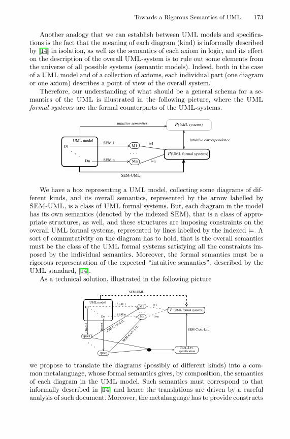
Towards a Rigorous Semantics of UML 173
Another analogy that we can establish between UML models and specifica-tions is the fact that the meaning of each diagram (kind) is informally describedby [14] in isolation, as well as the semantics of each axiom in logic, and its effecton the description of the overall UML-system is to rule out some elements fromthe universe of all possible systems (semantic models). Indeed, both in the caseof a UML model and of a collection of axioms, each individual part (one diagramor one axiom) describes a point of view of the overall system.
Therefore, our understanding of what should be a general schema for a se-mantics of the UML is illustrated in the following picture, where the UMLformal systems are the formal counterparts of the UML-systems.
P(UML formal systems)
P(UML systems)intuitive semantics
intuitive correspondence
. . .Mn
UML model
D1
Dn
|=1
|=n
M1
. . .
SEM-UML
SEM 1
SEM n
We have a box representing a UML model, collecting some diagrams of dif-ferent kinds, and its overall semantics, represented by the arrow labelled bySEM-UML, is a class of UML formal systems. But, each diagram in the modelhas its own semantics (denoted by the indexed SEM), that is a class of appro-priate structures, as well, and these structures are imposing constraints on theoverall UML formal systems, represented by lines labelled by the indexed |=. Asort of commutativity on the diagram has to hold, that is the overall semanticsmust be the class of the UML formal systems satisfying all the constraints im-posed by the individual semantics. Moreover, the formal semantics must be arigorous representation of the expected “intuitive semantics”, described by theUML standard, [14].
As a technical solution, illustrated in the following picture
Mn
SEM-CASL-LTL
P (UML formal systems)
CASL-LTLspecification
spec1
|=1
|=n
M1
tran
s1
tran
sn
specn
SEM-UML
SEM 1
SEM n
SEM-C
ASL-LTL
SEM-CASL-LTL
UML model
D1 . . .Dn
. . .
. . .
we propose to translate the diagrams (possibly of different kinds) into a com-mon metalanguage, whose formal semantics gives, by composition, the semanticsof each diagram in the UML model. Such semantics must correspond to thatinformally described in [14] and hence the translations are driven by a carefulanalysis of such document. Moreover, the metalanguage has to provide constructs
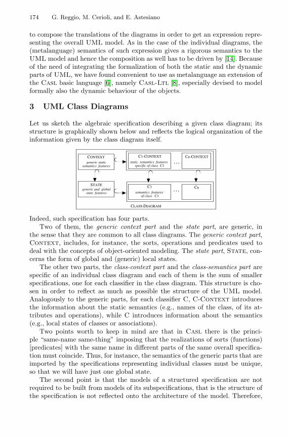
174 G. Reggio, M. Cerioli, and E. Astesiano
to compose the translations of the diagrams in order to get an expression repre-senting the overall UML model. As in the case of the individual diagrams, the(metalanguage) semantics of such expression gives a rigorous semantics to theUML model and hence the composition as well has to be driven by [14]. Becauseof the need of integrating the formalization of both the static and the dynamicparts of UML, we have found convenient to use as metalanguage an extension ofthe Casl basic language [6], namely Casl-Ltl [8], especially devised to modelformally also the dynamic behaviour of the objects.
3 UML Class Diagrams
Let us sketch the algebraic specification describing a given class diagram; itsstructure is graphically shown below and reflects the logical organization of theinformation given by the class diagram itself.
CONTEXT
generic staticsemantics features
STATEgeneric and global
state features
C1-CONTEXT
static semantics features specific of class C1
. . .Cn-CONTEXT
C1
semantics features of class C1
Cn. . .
CLASS-DIAGRAM
Indeed, such specification has four parts.Two of them, the generic context part and the state part, are generic, in
the sense that they are common to all class diagrams. The generic context part,Context, includes, for instance, the sorts, operations and predicates used todeal with the concepts of object-oriented modeling. The state part, State, con-cerns the form of global and (generic) local states.
The other two parts, the class-context part and the class-semantics part arespecific of an individual class diagram and each of them is the sum of smallerspecifications, one for each classifier in the class diagram. This structure is cho-sen in order to reflect as much as possible the structure of the UML model.Analogously to the generic parts, for each classifier C, C-Context introducesthe information about the static semantics (e.g., names of the class, of its at-tributes and operations), while C introduces information about the semantics(e.g., local states of classes or associations).
Two points worth to keep in mind are that in Casl there is the princi-ple “same-name same-thing” imposing that the realizations of sorts (functions)[predicates] with the same name in different parts of the same overall specifica-tion must coincide. Thus, for instance, the semantics of the generic parts that areimported by the specifications representing individual classes must be unique,so that we will have just one global state.
The second point is that the models of a structured specification are notrequired to be built from models of its subspecifications, that is the structure ofthe specification is not reflected onto the architecture of the model. Therefore,
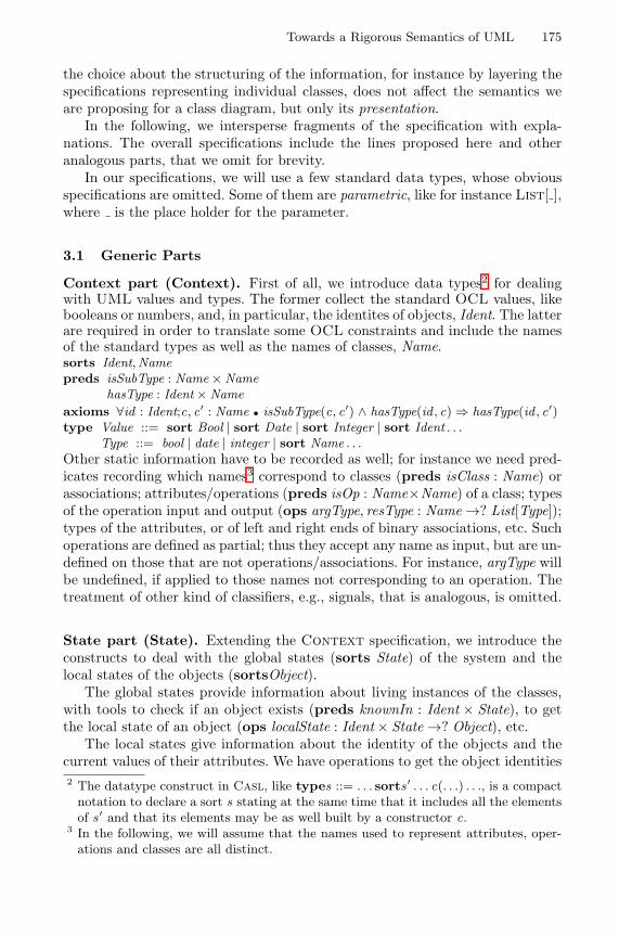
Towards a Rigorous Semantics of UML 175
the choice about the structuring of the information, for instance by layering thespecifications representing individual classes, does not affect the semantics weare proposing for a class diagram, but only its presentation.
In the following, we intersperse fragments of the specification with expla-nations. The overall specifications include the lines proposed here and otheranalogous parts, that we omit for brevity.
In our specifications, we will use a few standard data types, whose obviousspecifications are omitted. Some of them are parametric, like for instance List[ ],where is the place holder for the parameter.
3.1 Generic Parts
Context part (Context). First of all, we introduce data types2 for dealingwith UML values and types. The former collect the standard OCL values, likebooleans or numbers, and, in particular, the identites of objects, Ident. The latterare required in order to translate some OCL constraints and include the namesof the standard types as well as the names of classes, Name.sorts Ident,Namepreds isSubType : Name × Name
hasType : Ident × Nameaxioms ∀id : Ident;c, c′ : Name • isSubType(c, c′) ∧ hasType(id , c) ⇒ hasType(id , c′)type Value ::= sort Bool | sort Date | sort Integer | sort Ident . . .
Type ::= bool | date | integer | sort Name . . .Other static information have to be recorded as well; for instance we need pred-icates recording which names3 correspond to classes (preds isClass : Name) orassociations; attributes/operations (preds isOp : Name×Name) of a class; typesof the operation input and output (ops argType, resType : Name →? List[Type]);types of the attributes, or of left and right ends of binary associations, etc. Suchoperations are defined as partial; thus they accept any name as input, but are un-defined on those that are not operations/associations. For instance, argType willbe undefined, if applied to those names not corresponding to an operation. Thetreatment of other kind of classifiers, e.g., signals, that is analogous, is omitted.
State part (State). Extending the Context specification, we introduce theconstructs to deal with the global states (sorts State) of the system and thelocal states of the objects (sortsObject).
The global states provide information about living instances of the classes,with tools to check if an object exists (preds knownIn : Ident × State), to getthe local state of an object (ops localState : Ident × State →? Object), etc.
The local states give information about the identity of the objects and thecurrent values of their attributes. We have operations to get the object identities2 The datatype construct in Casl, like types ::= . . . sorts ′ . . . c(. . .) . . ., is a compact
notation to declare a sort s stating at the same time that it includes all the elementsof s ′ and that its elements may be as well built by a constructor c.
3 In the following, we will assume that the names used to represent attributes, oper-ations and classes are all distinct.
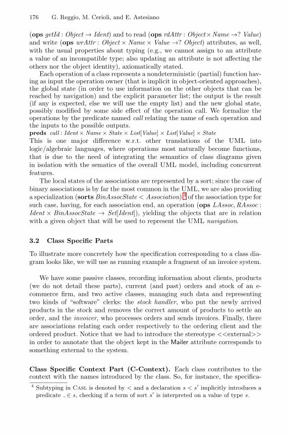
176 G. Reggio, M. Cerioli, and E. Astesiano
(ops getId : Object → Ident) and to read (ops rdAttr : Object×Name →? Value)and write (ops wrAttr : Object × Name × Value →? Object) attributes, as well,with the usual properties about typing (e.g., we cannot assign to an attributea value of an incompatible type; also updating an attribute is not affecting theothers nor the object identity), axiomatically stated.
Each operation of a class represents a nondeterministic (partial) function hav-ing as input the operation owner (that is implicit in object-oriented approaches),the global state (in order to use information on the other objects that can bereached by navigation) and the explicit parameter list; the output is the result(if any is expected, else we will use the empty list) and the new global state,possibly modified by some side effect of the operation call. We formalize theoperations by the predicate named call relating the name of each operation andthe inputs to the possible outputs.preds call : Ident × Name × State × List[Value] × List[Value] × StateThis is one major difference w.r.t. other translations of the UML intologic/algebraic languages, where operations most naturally become functions,that is due to the need of integrating the semantics of class diagrams givenin isolation with the sematics of the overall UML model, including concurrentfeatures.
The local states of the associations are represented by a sort; since the case ofbinary associations is by far the most common in the UML, we are also providinga specialization (sorts BinAssocState < Association) 4 of the association type forsuch case, having, for each association end, an operation (ops LAssoc,RAssoc :Ident × BinAssocState → Set[Ident]), yielding the objects that are in relationwith a given object that will be used to represent the UML navigation.
3.2 Class Specific Parts
To illustrate more concretely how the specification corresponding to a class dia-gram looks like, we will use as running example a fragment of an invoice system.
We have some passive classes, recording information about clients, products(we do not detail these parts), current (and past) orders and stock of an e-commerce firm, and two active classes, managing such data and representingtwo kinds of “software” clerks: the stock handler, who put the newly arrivedproducts in the stock and removes the correct amount of products to settle anorder, and the invoicer, who processes orders and sends invoices. Finally, thereare associations relating each order respectively to the ordering client and theordered product. Notice that we had to introduce the stereotype <<external>>in order to annotate that the object kept in the Mailer attribute corresponds tosomething external to the system.
Class Specific Context Part (C-Context). Each class contributes to thecontext with the names introduced by the class. So, for instance, the specifica-4 Subtyping in Casl is denoted by < and a declaration s < s ′ implicitly introduces a
predicate ∈ s, checking if a term of sort s ′ is interpreted on a value of type s.
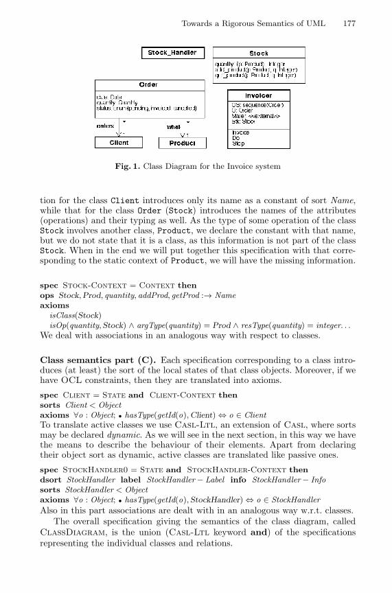
Towards a Rigorous Semantics of UML 177
Fig. 1. Class Diagram for the Invoice system
tion for the class Client introduces only its name as a constant of sort Name,while that for the class Order (Stock) introduces the names of the attributes(operations) and their typing as well. As the type of some operation of the classStock involves another class, Product, we declare the constant with that name,but we do not state that it is a class, as this information is not part of the classStock. When in the end we will put together this specification with that corre-sponding to the static context of Product, we will have the missing information.
spec Stock-Context = Context thenops Stock,Prod, quantity, addProd, getProd :→ Nameaxioms
isClass(Stock)isOp(quantity, Stock) ∧ argType(quantity) = Prod ∧ resType(quantity) = integer. . .
We deal with associations in an analogous way with respect to classes.
Class semantics part (C). Each specification corresponding to a class intro-duces (at least) the sort of the local states of that class objects. Moreover, if wehave OCL constraints, then they are translated into axioms.
spec Client = State and Client-Context thensorts Client < Objectaxioms ∀o : Object; • hasType(getId(o),Client) ⇔ o ∈ ClientTo translate active classes we use Casl-Ltl, an extension of Casl, where sortsmay be declared dynamic. As we will see in the next section, in this way we havethe means to describe the behaviour of their elements. Apart from declaringtheir object sort as dynamic, active classes are translated like passive ones.
spec StockHandler0 = State and StockHandler-Context thendsort StockHandler label StockHandler − Label info StockHandler − Infosorts StockHandler < Objectaxioms ∀o : Object; • hasType(getId(o), StockHandler) ⇔ o ∈ StockHandlerAlso in this part associations are dealt with in an analogous way w.r.t. classes.
The overall specification giving the semantics of the class diagram, calledClassDiagram, is the union (Casl-Ltl keyword and) of the specificationsrepresenting the individual classes and relations.
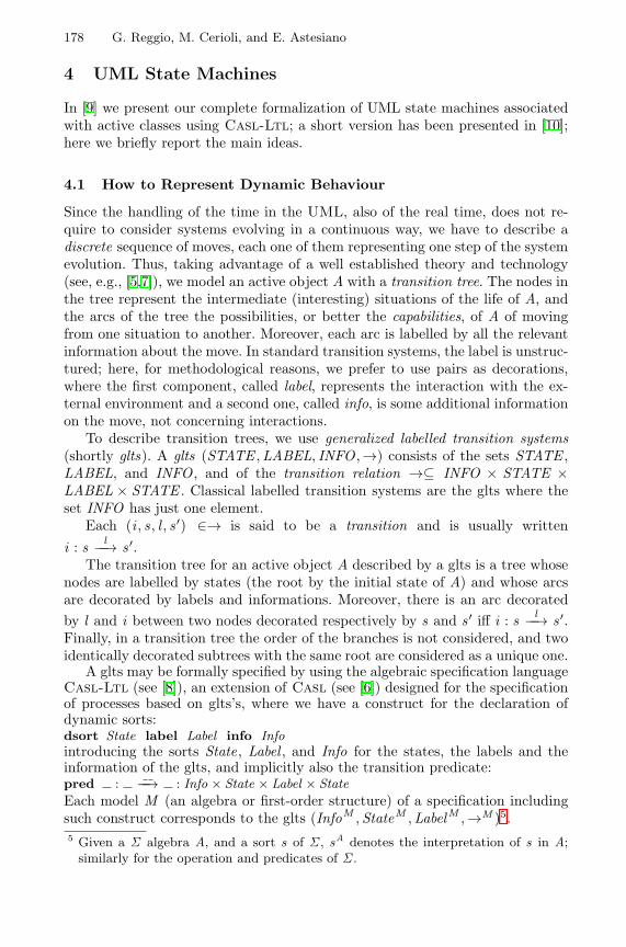
178 G. Reggio, M. Cerioli, and E. Astesiano
4 UML State Machines
In [9] we present our complete formalization of UML state machines associatedwith active classes using Casl-Ltl; a short version has been presented in [10];here we briefly report the main ideas.
4.1 How to Represent Dynamic Behaviour
Since the handling of the time in the UML, also of the real time, does not re-quire to consider systems evolving in a continuous way, we have to describe adiscrete sequence of moves, each one of them representing one step of the systemevolution. Thus, taking advantage of a well established theory and technology(see, e.g., [5,7]), we model an active object A with a transition tree. The nodes inthe tree represent the intermediate (interesting) situations of the life of A, andthe arcs of the tree the possibilities, or better the capabilities, of A of movingfrom one situation to another. Moreover, each arc is labelled by all the relevantinformation about the move. In standard transition systems, the label is unstruc-tured; here, for methodological reasons, we prefer to use pairs as decorations,where the first component, called label, represents the interaction with the ex-ternal environment and a second one, called info, is some additional informationon the move, not concerning interactions.
To describe transition trees, we use generalized labelled transition systems(shortly glts). A glts (STATE ,LABEL, INFO ,→) consists of the sets STATE ,LABEL, and INFO , and of the transition relation →⊆ INFO × STATE ×LABEL × STATE . Classical labelled transition systems are the glts where theset INFO has just one element.
Each (i , s, l , s ′) ∈→ is said to be a transition and is usually writteni : s l−−→ s ′.
The transition tree for an active object A described by a glts is a tree whosenodes are labelled by states (the root by the initial state of A) and whose arcsare decorated by labels and informations. Moreover, there is an arc decoratedby l and i between two nodes decorated respectively by s and s ′ iff i : s l−−→ s ′.Finally, in a transition tree the order of the branches is not considered, and twoidentically decorated subtrees with the same root are considered as a unique one.
A glts may be formally specified by using the algebraic specification languageCasl-Ltl (see [8]), an extension of Casl (see [6]) designed for the specificationof processes based on glts’s, where we have a construct for the declaration ofdynamic sorts:dsort State label Label info Infointroducing the sorts State, Label , and Info for the states, the labels and theinformation of the glts, and implicitly also the transition predicate:pred : −−→ : Info × State × Label × StateEach model M (an algebra or first-order structure) of a specification includingsuch construct corresponds to the glts (InfoM ,StateM ,LabelM ,→M )5.5 Given a Σ algebra A, and a sort s of Σ , sA denotes the interpretation of s in A;
similarly for the operation and predicates of Σ .
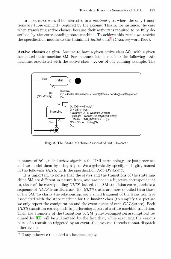
Towards a Rigorous Semantics of UML 179
In most cases we will be interested in a minimal glts, where the only transi-tions are those explicitly required by the axioms. This is, for instance, the casewhen translating active classes, because their activity is required to be fully de-scribed by the corresponding state machine. To achieve this result we restrictthe specification models to the (minimal) initial ones6 (Casl keyword free).
Active classes as glts. Assume to have a given active class ACL with a givenassociated state machine SM. For instance, let us consider the following statemachine, associated with the active class Invoicer of our running example. The
Initial
Invoicing
Invoice /OS = Order.allInstances-> Select(status = pending)->asSequence;Do;
Do [OS->noEmpty] /O = OS -> first;if Quantity(O) <= Quantity(O.what) {Stk.get_Product(Quantity(O);O.what); Mailer.SEND_INVOICE( ......);};OS = OS->excluding(O);Do;
Do [OS->Empty]
Stop
Stop
Fig. 2. The State Machine Associated with Invoicer
instances of ACL, called active objects in the UML terminology, are just processesand we model them by using a glts. We algebraically specify such glts, namedin the following GLTS, with the specification Acl-Dynamic.
It is important to notice that the states and the transitions of the state ma-chine SM are different in nature from, and are not in a bijective correspondenceto, those of the corresponding GLTS. Indeed, one SM-transition corresponds to asequence of GLTS-transitions and the GLTS-states are more detailed than thoseof the SM. To clarify the relationship, see a small fragment of the transition treeassociated with the state machine for the Invoicer class (to simplify the picturewe only report the configuration and the event queue of each GLTS-state). EachGLTS-transition corresponds to performing a part of a state machine transition.Then the atomicity of the transitions of SM (run-to-completion assumption) re-quired by [14] will be guaranteed by the fact that, while executing the variousparts of a transition triggered by an event, the involved threads cannot dispatchother events.6 If any, otherwise the model set becomes empty.
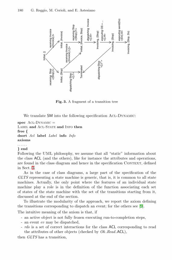
180 G. Reggio, M. Cerioli, and E. Astesiano
Initi
al, {
}
Initi
al, {
Invo
ice}
Initi
al, {
Sto
p}
Initi
al, {
Invo
ice,
Sto
p}
Invo
icin
g, {
Sto
p}
rece
ivin
g In
voic
e<
{Inv
oice
},t>
rece
ivin
g S
top
<{S
top}
,t1>
exec
utin
g O
S =
...
<{}
,t4>
disp
atch
ing
Sto
p<
{},t"
’>
rece
ivin
g S
top
<{S
top}
,t>
disp
atch
ing
Sto
p<
{},t’
>
Ter
min
ated
disp
atch
ing
Invo
ice
<{}
,t2>
exec
utin
g s
end(
Do)
<{D
o},t3
>
Invo
icin
g, {
Sto
p}
Invo
icin
g, {
Sto
p, D
o}
rece
ivin
g In
voic
e<
{Inv
oice
},t,{
}>
Fig. 3. A fragment of a transition tree
We translate SM into the following specification Acl-Dynamic:
spec Acl-Dynamic =Label and Acl-State and Info thenfree {dsort Acl label Label info Infoaxioms. . . . . .} endFollowing the UML philosophy, we assume that all “static” information aboutthe class ACL (and the others), like for instance the attributes and operations,are found in the class diagram and hence in the specification Context, definedin Sect. 3.
As in the case of class diagrams, a large part of the specification of theGLTS representing a state machine is generic, that is, it is common to all statemachines. Actually, the only point where the features of an individual statemachine play a role is in the definition of the function associating each setof states of the state machine with the set of the transitions starting from it,discussed at the end of the section.
To illustrate the modularity of the approach, we report the axiom definingthe transitions corresponding to dispatch an event; for the others see [9].The intuitive meaning of the axiom is that, if
- an active object is not fully frozen executing run-to-completion steps,- an event ev may be dispatched,- rds is a set of correct interactions for the class ACL corresponding to read
the attributes of other objects (checked by Ok Read ACL),then GLTS has a transition,
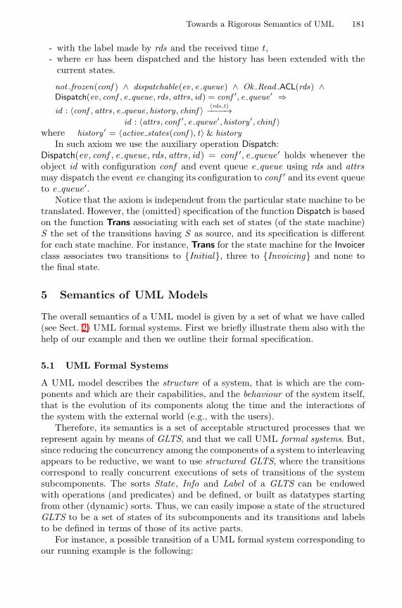
Towards a Rigorous Semantics of UML 181
- with the label made by rds and the received time t ,- where ev has been dispatched and the history has been extended with the
current states.
not frozen(conf ) ∧ dispatchable(ev , e queue) ∧ Ok Read ACL(rds) ∧Dispatch(ev , conf , e queue, rds, attrs, id) = conf ′, e queue ′ ⇒id : 〈conf , attrs, e queue, history , chinf 〉 〈rds,t〉−−−−→
id : 〈attrs, conf ′, e queue ′, history ′, chinf 〉where history ′ = 〈active states(conf ), t〉 & history
In such axiom we use the auxiliary operation Dispatch:Dispatch(ev , conf , e queue, rds, attrs, id) = conf ′, e queue ′ holds whenever theobject id with configuration conf and event queue e queue using rds and attrsmay dispatch the event ev changing its configuration to conf ′ and its event queueto e queue ′.
Notice that the axiom is independent from the particular state machine to betranslated. However, the (omitted) specification of the function Dispatch is basedon the function Trans associating with each set of states (of the state machine)S the set of the transitions having S as source, and its specification is differentfor each state machine. For instance, Trans for the state machine for the Invoicerclass associates two transitions to {Initial}, three to {Invoicing} and none tothe final state.
5 Semantics of UML Models
The overall semantics of a UML model is given by a set of what we have called(see Sect. 2) UML formal systems. First we briefly illustrate them also with thehelp of our example and then we outline their formal specification.
5.1 UML Formal Systems
A UML model describes the structure of a system, that is which are the com-ponents and which are their capabilities, and the behaviour of the system itself,that is the evolution of its components along the time and the interactions ofthe system with the external world (e.g., with the users).
Therefore, its semantics is a set of acceptable structured processes that werepresent again by means of GLTS, and that we call UML formal systems. But,since reducing the concurrency among the components of a system to interleavingappears to be reductive, we want to use structured GLTS, where the transitionscorrespond to really concurrent executions of sets of transitions of the systemsubcomponents. The sorts State, Info and Label of a GLTS can be endowedwith operations (and predicates) and be defined, or built as datatypes startingfrom other (dynamic) sorts. Thus, we can easily impose a state of the structuredGLTS to be a set of states of its subcomponents and its transitions and labelsto be defined in terms of those of its active parts.
For instance, a possible transition of a UML formal system corresponding toour running example is the following:
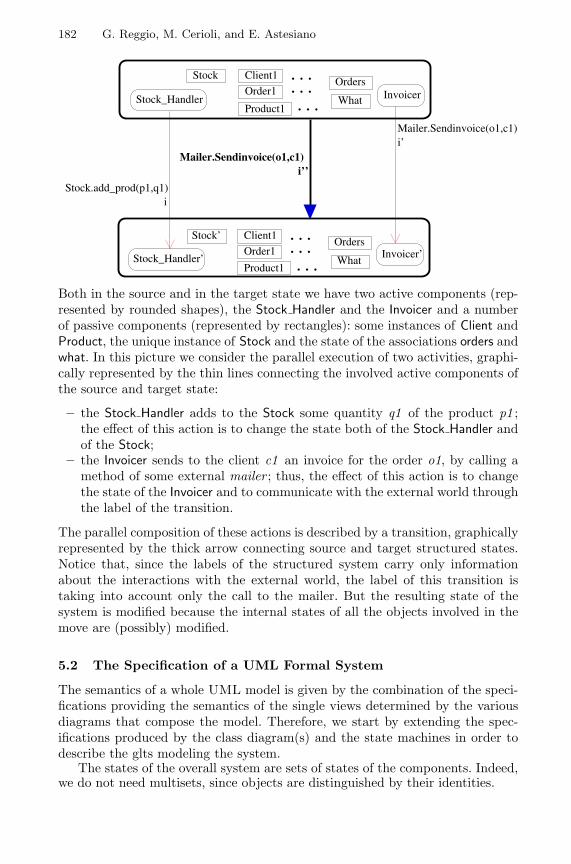
182 G. Reggio, M. Cerioli, and E. Astesiano
Stock.add_prod(p1,q1)i
Mailer.Sendinvoice(o1,c1)i’
Stock_Handler
. . .Order1
Stock Client1
Product1
Orders
What. . .. . .
Stock_Handler’
. . .Order1
Stock’ Client1
Product1
Orders
What. . .. . .
Mailer.Sendinvoice(o1,c1)i’’
Invoicer’
Invoicer
Both in the source and in the target state we have two active components (rep-resented by rounded shapes), the Stock Handler and the Invoicer and a numberof passive components (represented by rectangles): some instances of Client andProduct, the unique instance of Stock and the state of the associations orders andwhat. In this picture we consider the parallel execution of two activities, graphi-cally represented by the thin lines connecting the involved active components ofthe source and target state:
– the Stock Handler adds to the Stock some quantity q1 of the product p1 ;the effect of this action is to change the state both of the Stock Handler andof the Stock;
– the Invoicer sends to the client c1 an invoice for the order o1, by calling amethod of some external mailer ; thus, the effect of this action is to changethe state of the Invoicer and to communicate with the external world throughthe label of the transition.
The parallel composition of these actions is described by a transition, graphicallyrepresented by the thick arrow connecting source and target structured states.Notice that, since the labels of the structured system carry only informationabout the interactions with the external world, the label of this transition istaking into account only the call to the mailer. But the resulting state of thesystem is modified because the internal states of all the objects involved in themove are (possibly) modified.
5.2 The Specification of a UML Formal System
The semantics of a whole UML model is given by the combination of the speci-fications providing the semantics of the single views determined by the variousdiagrams that compose the model. Therefore, we start by extending the spec-ifications produced by the class diagram(s) and the state machines in order todescribe the glts modeling the system.
The states of the overall system are sets of states of the components. Indeed,we do not need multisets, since objects are distinguished by their identities.
Towards a Rigorous Semantics of UML 183
type State ::= Λ | sort Object | sort Association | || (State; State)op || : State × State → State assoc, comm, idem, unit: ΛThe specification of the labels of the system (System-Label), based on theinteractions with the external environment, is omitted. The informations of thegeneralized transitions will be a set of stimuli. Indeed, to be able to evaluatethe satisfaction of a sequence diagram by a UML formal system M we needto record for each transition of M which are the stimuli exchanged during suchtransition. The specification Stimulus, describing the stimuli, that is the thetrivial translation into Casl of the UML stimuli (see [14] p. 2-86) is omitted aswell.
In a context extending the specifications Class Diagram, Acl-Dynamic1 ,. . . , Acl-Dynamicp , System-Label and FiniteSet[Stimulus], we can de-scribe the dynamics of the elements of sort Statedsort State label System-Label info FinSet [Stimulus]
It is worth noting that to state the behavioural axioms we need some temporallogic combinators available in Casl-Ltl that we have no space to illustrate here.The expressive power of such temporal logic will be also crucial for the translationof sequence diagrams, though they are not discussed here.
Though most of the identifications needed are already given by the “same-name same-thing” principle of Casl, we also need axioms stating that an identityis known in a system state iff it corresponds to a component of the system, thatcan be easily inductively defined, or axioms stating that for active classes gettingthe identity corresponds to selecting the identity component of their state tuples.There are several such axioms, that, though quite trivial to be expressed, wouldproduce a long boring list.
Much more interesting are the axioms describing the transitions of the over-all system. For instance, we can state that we can add to the source and thetarget of a transition any number of components that do not participate intothe transition: axiom inf : s l−−→ s ′ ⇒ inf : s||s0 l−−→ s ′||s0 .
Let us now show how to compose the transitions of the individual activecomponents, using several auxiliary functions, whose axiomatization we omit forlack of room. Assume that we have, as part of a state s, a group of active ob-jects ai which may perform some transitions infi : ai
li−−→ a ′i , accordingly to the
specification of their active classes. Then, we can compose such transitions intoa transition of s only if the interactions appearing on the li ’s, and on the label lof the resulting transition are pairwise matched, i.e., any thing sent is receivedby the addressee, including the external environment, and only sent things arereceived (this is checked by the predicate Ok Labels) and the interactions corre-sponding to read the attributes of passive objects are in agreement with theiractual values (this is checked by the predicate Read Attributes). If these condi-tions are satisfied, then the system can move into a new state where the activeobjects are evolved into the a ′
i ’s, the passive components of s are updated andsome new components may be possibly added.
184 G. Reggio, M. Cerioli, and E. Astesiano
∧ni=1 infi : ai
li−−→ a ′i ∧
Ok Labels(l1 . . . ln l) ∧Read Attributes(l1 . . . ln l , pss) ∧Updated(l1 . . . ln l , pss) = pss ′ ∧Created(l1 . . . ln l) = oss ⇒Stimuli Of(l1 . . . ln l , inf1 , . . . , infn) : a1 || . . . ||an ||pss l−−→ a ′
1 || . . . ||a ′n ||pss ′||oss
It is interesting to note that there is no guarantee that the specification of theoverall system is consistent. Indeed, if, for instance, the constraints imposed bythe class diagrams are not met by the behaviour described by the state machines,then the UML model corresponds to no systems and this is shown by the factthat the overall specification is inconsistent (i.e., it has no models).
6 Conclusion
Our work stems from the belief, supported by concrete experience, that analysingthe UML with different techniques helps the understanding, especially when anofficial formal definition of its semantics is lacking and many proposal for im-provements and extensions are under way. Indeed, this kind of analysis is ex-plicitly encouraged by some members of the OMG involved in the definition ofUML (Bran Selic during the discussion at the <<UML>> 2000 Workshop “Dy-namic Behaviour in UML Models: Semantic Questions”, York, October 2000).Moreover, we have already shown in [10] how this kind of analysis can lead tospot problematic points and offer various alternatives for a precise definition.
With respect to the proposal of a standard definition by an OO metamod-elling approach, like the one advocated by [3], our work is complementary, intwo senses. First of all, it provides a basic technique for modelling dynamic be-haviour, which is based on the twenty years long and successful experience ofCCS and the like (labelled transition systems), already used for the full formaldefinition of Ada ([1]). That technique is adequate for modelling all dynamicfeatures of UML; for example by this technique we are currently working onsequence diagrams; some other kinds of diagrams that we have partly analyzed,and that we conjecture can be added to our schema without major problems,are
– the collaboration diagrams, being rather similar to the sequence diagrams;– the activity diagrams, as they are a specialization of the statechart diagrams.
Thus it would be interesting to explore the possibility of adopting this tech-nique as a basis in the so called dynamic-core sketched in [3], which is admittedlyrather preliminary. For a proposal in that direction see [2]. A point that we wantto stress again is that our approach is supporting the multiview philosophy, inthe sense that each part of a UML model has a proper formalization that isintegrated with those of the other parts. Moreover, we are considering full UMLand this is quite important, because it is often the case that the semantics givenfor a restricted part of UML in isolation is useless when trying to uplift it tothe full UML.
Towards a Rigorous Semantics of UML 185
For instance, even from this partial work concerning just two kinds of dia-grams, it results clear that the separation of concerns apparently achieved byusing class diagrams to describe the system structure and state machines tocapture the system dynamics is limited. Indeed, the class diagram imposes re-strictions on the dynamic behaviour of the objects, through the constraints onthe operations and on the classes. Vice versa, a state machine cannot be con-sidered in isolation, as we need to know whether it is associated with an activeor with a passive class and which are the operations/signals/attributes of suchclass and of the other classes. Moreover, we have also found that we need toknow how a UML model interacts with its external environment, in order todescribe the labels of the overall system (see Sect. 5.2).
We expect that furthering our investigation to other kinds of diagrams morerelationships among the parts of a UML model will be exposed, deepening ourunderstanding of the UML and paving the way for better new versions and astandard complete definition of its semantics.
References
1. E. Astesiano, C. Bendix Nielsen, N. Botta, A. Fantechi, A. Giovini, P. Inverardi,E. Karlsen, F. Mazzanti, J. Storbank Pedersen, G. Reggio, and E. Zucca. TheDraft Formal Definition of Ada. Deliverable, CEC MAP project: The Draft FormalDefinition of ANSI/STD 1815A Ada, 1986.
2. E. Astesiano and G. Reggio. A Proposal of a Dynamic Core for UML Metamod-elling with MML. Technical Report DISI-TR-01-1, DISI – Universita di Genova,Italy, 2001.ftp://ftp.disi.unige.it/person/ReggioG/AstesianoReggio01a.pdf.
3. T. Clark, A. Evans, S. Kent, S. Brodsky, and S. Cook. A Feasibility Study inRearchitecting UML as a Family of Languages using a Precise OO Meta-ModelingApproach - Version 1.0. (September 2000). Available athttp://www.cs.york.ac.uk/puml/mmf.pdf., 2000.
4. R. France and B. Rumpe, editors. <<UML>>’99 - The Unified Modelling Lan-guage. Number 1723 in Lecture Notes in Conputer Science. Springer Verlag, 1999.
5. R. Milner. Communication and Concurrency. Prentice Hall, London, 1989.6. The CoFI Task Group on Language Design. Casl Summary. Version 1.0. Technical
report, 1998. Available onhttp://www.brics.dk/Projects/CoFI/Documents/CASL/Summary/.
7. G. Plotkin. An Operational Semantics for CSP. In D. Bjorner, editor, Proc. IFIPTC 2-Working conference: Formal description of programming concepts. North-Holland, Amsterdam, 1983.
8. G. Reggio, E. Astesiano, and C. Choppy. Casl-Ltl : A Casl Extension for Dy-namic Reactive Systems – Summary. Technical Report DISI-TR-99-34, DISI –Universita di Genova, Italy, 1999.ftp://ftp.disi.unige.it/person/ReggioG/ReggioEtAll99a.ps.
9. G. Reggio, E. Astesiano, C. Choppy, and H. Hussmann. A Casl Formal Definitionof UML Active Classes and Associated State Machines. Technical Report DISI-TR-99-16, DISI – Universita di Genova, Italy, 1999. Revised March 2000. Availableat ftp://ftp.disi.unige.it/person/ReggioG/Reggio99b.ps.

186 G. Reggio, M. Cerioli, and E. Astesiano
10. G. Reggio, E. Astesiano, C. Choppy, and H. Hussmann. Analysing UML ActiveClasses and Associated State Machines – A Lightweight Formal Approach. InT. Maibaum, editor, Proc. FASE 2000 - Fundamental Approaches to Software En-gineering, number 1783 in Lecture Notes in Computer Science. Springer Verlag,Berlin, 2000.
11. G. Reggio, A. Knapp, B. Rumpe, B. Selic, and R. Wieringa (editors). Dy-namic Behaviour in UML Models: Semantic Questions. Technical report, Ludwig-Maximilian University, Munich (Germany), 2000.
12. J. Rumbaugh, I. Jacobson, and G. Booch. The Unified Modeling Language Refer-ence Manual. Object Technology Series. Addison-Wesley, 1999.
13. S.Kent, A.Evans, and B. Rumpe. UML Semantics FAQ . In A. Moreira andS. Demeyer, editors, ECOOP’99 Workshop Reader. Springer Verlag, Berlin, 1999.
14. UML Revision Task Force. OMG UML Specification, 1999. Available athttp://uml.shl.com.
Towards Development of Secure SystemsUsing UMLsec
Jan Jurjens?
Computing Laboratory, University of Oxford, GB
Abstract. We show how UML (the industry standard in object-orientedmodelling) can be used to express security requirements during systemdevelopment. Using the extension mechanisms provided by UML, we in-corporate standard concepts from formal methods regarding multi-levelsecure systems and security protocols. These definitions evaluate dia-grams of various kinds and indicate possible vulnerabilities.On the theoretical side, this work exemplifies use of the extension mecha-nisms of UML and of a (simplified) formal semantics for it. A more prac-tical aim is to enable developers (that may not be security specialists) tomake use of established knowledge on security engineering through themeans of a widely used notation.
1 Introduction
There is presently an increased need to consider security aspects when develop-ing systems (that may e.g. communicate over untrusted networks). This is notalways met by adequate knowledge on the side of the developer. This is prob-lematic since in practice, security is compromised most often not by breakingthe dedicated mechanisms (such as encryption or security protocols), but byexploiting weaknesses in the way they are being used [And94]. Thus securitymechanisms cannot be “blindly” inserted into a security-critical system, but theoverall system development must take security aspects into account.
Object-oriented systems offer a very suitable framework for considering se-curity due to their encapsulation and modularisation principles.
The Unified Modeling Language (UML) [RJB99] is an industry standardfor specifying object-oriented software systems. Compared to other modellinglanguages, UML is very precisely defined.
The aim of this work is to use UML to encapsulate knowledge on prudentsecurity engineering and thereby make it available to developers not specialisedin security.
This work profits from a work towards a formal semantics for UML e. g. in[EFLR99,RACH00]. Its aim is to make formalism have an impact in the actualsoftware development process, [Huß99,AR00].? http://www.jurjens.de/jan – [email protected] - Supported by the Studien-
stiftung des deutschen Volkes and the Computing Laboratory.
H. Hussmann (Ed.): FASE 2001, LNCS 2029, pp. 187–200, 2001.c© Springer-Verlag Berlin Heidelberg 2001
188 J. Jurjens
For space limitations, we present our results in the framework of a simplifiedfragment of UML (in its current version 1.3 [For99]), the extension to the wholeof the actual UML is under development [Jur01b].
After presenting some background and related work in the following subsec-tion, we summarise our use of UML in the next section. In the later sectionswe show how to use four central kinds of diagrams of UML to develop security-critical systems. We end with a conclusion and indicate future work.
1.1 Background and Related Work
A traditional way of ensuring security in computer systems is to design multi-level secure systems (LaPadula, Bell 1973). There are levels of sensitivity of data(usually high and low). To ensure confidentiality of data, one enforces the policythat information always flows up: low data may influence high data, but notvc. vs. (the opposite of this condition provides data integrity ; thus also integrityis implicitly covered by our approach). To avoid covert channels one can usethe notion of noninterference (Goguen, Meseguer 1982; cf. e. g. [Jur00]). Securecommunication over untrusted networks requires specific mechanisms such asencryption and cryptographic protocols.
There has been much work on security using formal methods (e. g. [BAN89,RWW94,Low96,AJ00,Jur01c]), mostly about security protocols or secure infor-mation flow.
[And94] suggests to use software engineering techniques to ensure security.[DS00] proposes to “extend the syntax and semantics of standards such as UMLto address security concerns”. We are not aware of any published work towardsthis goal.
Our work depends on concepts from the considerable work towards providinga formal semantics for UML (e. g. [BGH+98,EFLR99,GPP98,RCA00,RACH00,BD00,Ove00]). In particular the security notions concerning behaviour cannotbe formulated at the level of abstract syntax, requiring a formal semantics toexpress and reason about the security requirements. As a formal semantics forUML is subject of ongoing research, we use a (simplified) semantics tailored toour needs for the time being. It would be preferable to employ a universallydefined formal semantics, therefore our work may contribute to exemplify theneed for a formal semantics for UML.
2 Developing Secure Systems with UML
UML consists of diagram types describing views on a system (an excellent in-troduction is [SP00]). We use an extension of UML (called UMLsec) to specifystandard security requirements on security-critical systems. Our results may beused with any process; security-critical systems usually require an iterative ap-proach (e. g. the “Spiral”) [And94].
We concentrate on the most important kinds of diagrams for describingobject-oriented software systems (following [RACH00]):
Towards Development of Secure Systems Using UMLsec 189
Class diagrams define the static structure of the system: classes with at-tributes and operations/signals and relationships between classes. We usethem to ensure that exchange of data obeys security levels.
Statechart diagrams give the dynamic behaviour of an individual object:events may cause state in change or actions. We use them to prevent in-direct information flow from high to low values within an object.
Interaction diagrams describe interaction between objects via message ex-change. We use sequence diagrams to ensure correctness of security-criticalinteraction between objects (especially in distributed object systems).
Since security of a software system depends on the security of the underlyingphysical layer, we additionally use deployment diagrams to ensure that secu-rity requirements on communication are met by the physical layer.
To specify security levels we use the UML extension construct of a tag toindicate model elements with high security level.
We formulate our concepts at this point on the level of abstract syntax asfar as possible (i. e. those concerning static aspects), given in set-theoreticalterms for brevity. Behavioural aspects (modeled using statechart and sequencediagrams) can not be treated this way. In absence of a general formal semanticswe use a specifically defined one which covers just the aspects needed and to theneeded degree of detail, to follow space restrictions (a more complete account isto be found in [Jur01b]).
We stress that the aspects that are left out (such as association and general-isation in the case of class diagrams) can and should be used in the context ofour usage of UML; they do not appear in our presentation simply because theyare not needed to specify the considered properties (and for lack of space).
It should also be stressed that the formal semantics is used here only toconvey our ideas on how to model security aspects of systems using UML andnot to provide a semantics for general use. We will translate our definitions to agenerally defined formal semantics when available.
3 Classes and State
We give the abstract syntax for class models. Besides the usual information onattributes and operations/signals we also have interfaces. Additionally, the tag{high} is used to mark data items (attributes, arguments of operations or signalsor return values of operations) of the corresponding security level (absence of thistag is interpreted as the level low).1 In the concrete syntax, these tags are writtenbehind the data types. Following [RACH00] we assume that the attributes arefully encapsulated by the operations, i. e. an attribute of a class can be read andupdated only by the class operations.
1 More precisely, UML provides tag-value pairs. Here we use the convention that wherethe values are supposed to be boolean values, they need not be written (then presenceof the label denotes the value true, and absence denotes false).
190 J. Jurjens
For brevity, our abstract syntax only gives the aspects we use to specify oursecurity condition. [EFLR99] has a more complete account.
An attribute specification A = (att name, att type, init value, att tags) is givenby a name att name, a type att tags, an initial value init value2 and a set of tagsatt tags (here we only care if it contains the tag {high} or not, determining thesecurity level of the attribute).
An operation specification O = (op name, Arguments, op type, re tags) is givenby a name op name, a set of Arguments, the type op type of the return value anda set re tags of tags denoting the security level of the return value. The set ofarguments may be empty and the return type may be the empty type ∅ denotingabsence of a return value. An argument A = (arg name, arg type, arg tags) isgiven by its name arg name, its type arg type and a set arg tags denoting thesecurity level of the argument.
A signal specification is like an operation specification, except that there isno return type and no corresponding set of tags.
An interface I = (int name, Operations, Signals) is given by a name int nameand sets of operation names Operations and signal names Signals giving theoperations and signals that can be called or sent through it.
A class model C = (class name, AttSpecs, OpSpecs, SigSpecs, Interfaces, State)is given by a name class name, a set of attribute specifications AttSpecs, a setof operation specifications OpSpecs, a set of signal specifications SigSpecs, a setof class interfaces Interfaces and a statechart diagram State giving the objectbehaviour. We require that in the set of attribute specifications, the attributenames are mutually distinct, so that an attribute is uniquely specified by its nameand the name of its class (and similarly for operation and signal specificationsand class interfaces).
3.1 Statechart Diagrams
We fix a set Var of (typed) variables x, z, y, . . . used in statechart diagrams. Atthis point, we only consider simple states with one thread of execution, becausethe formal semantics of more complex features raises some questions [RACH00].
We define the notion of a statechart diagram for a given class model C: Astatechart diagram S = (States, init state, Transitions) is given by a set of States(that includes the initial state init state) and a set of Transitions. (On the levelof concrete syntax, the initial state is the state with an in-going transition fromthe start marker.)
A statechart transition t = (source, event, guard, Actions, target) has a sourcestate, an event, a guard, a list of Actions and a target state. Here an event is thename of an operation or signal with a list of distinct variables as arguments thatis assumed to be well-typed (e. g. op(x, y, z)). Let the set Assignments consistof all partial functions that assign to each variable and each attribute of theclass C a value of its type (partiality arises from the fact that variables maybe undefined). A guard is a function g : Assigments → Bool evaluating each2 We assume that these are specified in the class rather than by the creating object.
Towards Development of Secure Systems Using UMLsec 191
assignment to a boolean value. (On the level of UML’s concrete syntax, it isleft open how to write such guards; often it is done in OCL.) An action can beeither to assign a value v to an attribute a (written a := v), to call an operationop resp. to send a signal sig with values v1, . . . , vn (written op(v1, . . . , vn) resp.sig(v1, . . . , vn)), or to return values v1, . . . , vn as a response to an earlier callof the operation op (written returnop(v1, . . . , vn)). In each case, the values canbe constants, variables or attributes (and need to be well-typed). In the case ofoutput actions (calling an operation or sending a signal) we include the types ofthe arguments (and possibly of the return value) together with any security tags.(This is not necessary in the usual UML syntax; we need this extra informationlater.)
Interpreting statechart diagrams. To define our security condition on statechartdiagrams we need to interpret them as state machines. Due to space constraintswe can only sketch this interpretation, a detailed account is in [Jur01b].
Suppose we are given a class model C with a statechart diagram S. We definethe associated state machine MS
def= (S, i, T ) to consist of
– a set of states S def= States × Assignments,– an initial state i
def= (init state, init as) (where the initial assignment init asmaps each attribute to its initial value and is undefined on the set of vari-ables) and
– a set T of state machine transitions t = (s, e, A, s′) (for states s, s′, a triggere and a list of actions A) defined as follows. A trigger is the name of anoperation or signal with a list of (suitably typed) values as arguments.
Firstly, for any assignment function φ, a list of variable or attribute namesx = (x1, . . . , xn) and a list of values v = (v1, . . . , vn) of the correspondingtypes, we define φ[x 7→ v] by φ[x 7→ v](z) def= φ(z) for an attribute or variable z
not in x and φ[x 7→ v](xi)def= vi for i = 1, . . . , n.
Suppose we are given a transition t = (source, event, guard, Actions, target) ∈Transitions in the statechart diagram (where the event has the list of vari-ables x = (x1, . . . , xn)), a corresponding list of values v = (v1, . . . , vn) andan assignment φ such that guard(φ[x 7→ v]) = true. Denote the list of at-tributes that are assigned new values in the list of Actions by a and thecorresponding list of values by w. We define the state machine transitiontv,φ
def= ((source, φ), event(v), Actions′, (target, φ[x 7→ v][a 7→ w])) where event(v)is the trigger obtained from event by substituting the values v for the variablesx and Actions′ is the list of actions obtained from Actions by removing theattribute assignments and by instantiating any variables or attributes appear-ing as parameters using the assignment (φ[x 7→ v])[a 7→ w]. Then we defineT def= {tv,φ : guard(φ[x 7→ v]) = true}.
Assume for the moment that the state machine under consideration is deter-ministic in the sense that at any state, any given trigger can fire at most onetransition. Any state s of the state machine defines a function [s] from sequences
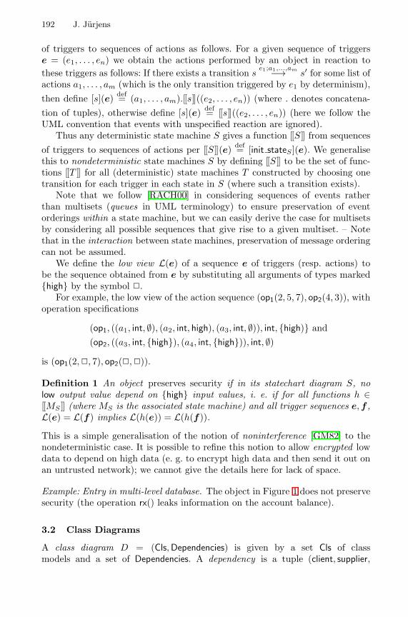
192 J. Jurjens
of triggers to sequences of actions as follows. For a given sequence of triggerse = (e1, . . . , en) we obtain the actions performed by an object in reaction tothese triggers as follows: If there exists a transition s
e1;a1,...,am−→ s′ for some list ofactions a1, . . . , am (which is the only transition triggered by e1 by determinism),then define [s](e) def= (a1, . . . , am).[[s ]] ((e2, . . . , en)) (where . denotes concatena-tion of tuples), otherwise define [s](e) def= [[s ]] ((e2, . . . , en)) (here we follow theUML convention that events with unspecified reaction are ignored).
Thus any deterministic state machine S gives a function [[S ]] from sequencesof triggers to sequences of actions per [[S ]] (e) def= [init stateS ](e). We generalisethis to nondeterministic state machines S by defining [[S ]] to be the set of func-tions [[T ]] for all (deterministic) state machines T constructed by choosing onetransition for each trigger in each state in S (where such a transition exists).
Note that we follow [RACH00] in considering sequences of events ratherthan multisets (queues in UML terminology) to ensure preservation of eventorderings within a state machine, but we can easily derive the case for multisetsby considering all possible sequences that give rise to a given multiset. – Notethat in the interaction between state machines, preservation of message orderingcan not be assumed.
We define the low view L(e) of a sequence e of triggers (resp. actions) tobe the sequence obtained from e by substituting all arguments of types marked{high} by the symbol 2.
For example, the low view of the action sequence (op1(2, 5, 7), op2(4, 3)), withoperation specifications
(op1, ((a1, int, ∅), (a2, int, high), (a3, int, ∅)), int, {high)} and(op2, ((a3, int, {high}), (a4, int, {high})), int, ∅)
is (op1(2,2, 7), op2(2,2)).
Definition 1 An object preserves security if in its statechart diagram S, nolow output value depend on {high} input values, i. e. if for all functions h ∈[[MS ]] (where MS is the associated state machine) and all trigger sequences e,f ,L(e) = L(f) implies L(h(e)) = L(h(f)).
This is a simple generalisation of the notion of noninterference [GM82] to thenondeterministic case. It is possible to refine this notion to allow encrypted lowdata to depend on high data (e. g. to encrypt high data and then send it out onan untrusted network); we cannot give the details here for lack of space.
Example: Entry in multi-level database. The object in Figure 1 does not preservesecurity (the operation rx() leaks information on the account balance).
3.2 Class Diagrams
A class diagram D = (Cls, Dependencies) is given by a set Cls of classmodels and a set of Dependencies. A dependency is a tuple (client, supplier,
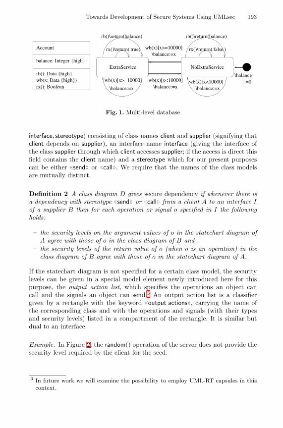
Towards Development of Secure Systems Using UMLsec 193
Account
balance: Integer {high}
wb(x: Data {high})rb(): Data {high}
rx(): Boolean
ExtraService NoExtraService
wb(x)[x>=10000]
\balance:=xwb(x)[x<10000]
\balance:=x
rx()\return( )true rx()\return( )false
rb()\return(balance)rb()\return(balance)
\balance:=xwb(x)[x<10000]
wb(x)[x>=10000]\balance:=x
\balance:=0
Fig. 1. Multi-level database
interface, stereotype) consisting of class names client and supplier (signifying thatclient depends on supplier), an interface name interface (giving the interface ofthe class supplier through which client accesses supplier; if the access is direct thisfield contains the client name) and a stereotype which for our present purposescan be either 〈〈send〉〉 or 〈〈call〉〉. We require that the names of the class modelsare mutually distinct.
Definition 2 A class diagram D gives secure dependency if whenever there isa dependency with stereotype 〈〈send〉〉 or 〈〈call〉〉 from a client A to an interface Iof a supplier B then for each operation or signal o specified in I the followingholds:
– the security levels on the argument values of o in the statechart diagram ofA agree with those of o in the class diagram of B and
– the security levels of the return value of o (when o is an operation) in theclass diagram of B agree with those of o in the statechart diagram of A.
If the statechart diagram is not specified for a certain class model, the securitylevels can be given in a special model element newly introduced here for thispurpose, the output action list, which specifies the operations an object cancall and the signals an object can send.3 An output action list is a classifiergiven by a rectangle with the keyword 〈〈output actions〉〉, carrying the name ofthe corresponding class and with the operations and signals (with their typesand security levels) listed in a compartment of the rectangle. It is similar butdual to an interface.
Example. In Figure 2, the random() operation of the server does not provide thesecurity level required by the client for the seed.
3 In future work we will examine the possibility to employ UML-RT capsules in thiscontext.
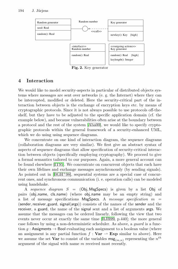
194 J. Jurjens
Random generator
seed: Real
random(): Real
Random number
newkey(): Key
Key generator
{high}
<<outgoing actions>>Key generator
random(): Real
keylength(): Integer
{high}random(): Real
Random number«interface>>
<<call>>
Fig. 2. Key generator
4 Interaction
We would like to model security-aspects in particular of distributed objects sys-tems where messages are sent over networks (e. g. the Internet) where they canbe intercepted, modified or deleted. Here the security-critical part of the in-teraction between objects is the exchange of encryption keys etc. by means ofcryptographic protocols. Since it is not always possible to use protocols off-the-shelf, but they have to be adjusted to the specific application domain (cf. theexample below), and because vulnerabilities often arise at the boundary betweena protocol and the rest of the system [Aba00], we would like to specify crypto-graphic protocols within the general framework of a security-enhanced UML,which we do using using sequence diagrams.
We concentrate on one kind of interaction diagram, the sequence diagrams(collaboration diagrams are very similar). We first give an abstract syntax ofaspects of sequence diagrams that allow specification of security-critical interac-tion between objects (specifically employing cryptography). We proceed to givea formal semantics tailored to our purposes. Again, a more general account canbe found elsewhere [IT95]. We concentrate on concurrent objects that each havetheir own lifelines and exchange messages asynchronously (by sending signals).As pointed out in [BGH+98], sequential systems are a special case of concur-rent ones, and synchronous communication (i. e. operation calls) can be modeledusing handshake.
A sequence diagram S = (Obj, MsgSpecs) is given by a list Obj ofpairs (obj name, cls name) (where obj name may be an empty string) anda list of message specifications MsgSpecs. A message specification m =(sender, receiver, guard, signal(args)) consists of the names of the sender and thereceiver, a guard, the name of the signal sent and a list of arguments args. Weassume that the messages can be ordered linearly, following the view that twoevents never occur at exactly the same time [RJB99, p.440]; the more generalcase follows by using a non-deterministic scheduler. As above, a guard is a func-tion g : Assigments → Bool evaluating each assignment to a boolean value (wherean assignment is any partial function f : Var ⇀ Exp similar to above). Herewe assume the set Var to consist of the variables msg(m,n) representing the nth
argument of the signal with name m received most recently.
Towards Development of Secure Systems Using UMLsec 195
We define the data type Exp of cryptographic messages that can be ex-changed during the interaction. We assume a set D of basic data values. The setExp contains the expressions defined inductively by the grammar
E ::= expressiond data value (d ∈ D)K key (K ∈ Keys)x variable (x ∈ Var)E1 :: E2 concatenation{E}e encryption (e ∈ Keys ∪ Var)Dece(E) decryption (e ∈ Keys ∪ Var)
Here we consider asymmetric encryption, so the set Keys is the disjoint unionof the sets of private and public keys, where the private keys correspondingto a public key K is denoted K−1. We assume DecK−1({E}K) = E, and forthe following example (for RSA signing) also {DecK−1(E)}K = E (for all E ∈Exp, K, K−1 ∈ Keys), and that no other equations except those implied bythese hold. We write Msg for the set of messages of the form sig(E1, . . . , En)where sig is a signal with n arguments of type Exp.
KC
KCA
:client :server
[{msg } =C::msg
[{msg } =S::k
(msg )}resp,2
init(NC C
S K−1S
KCSxchd({m} )
init,2init,3
C−1,K ,Dec (C::K ))
resp,3
{DecCK−1 =k k’::N ]C
C K
CCS C K K S
CA−1
resp(N ,{Dec (K :::N )} ,Dec (S::K ))
Fig. 3. Variant of TLS
Example: Proposed variant of TLS. The protocol in Figure 3 has been proposedin [APS99] as a variant of the handshake protocol of TLS (the successor ofthe Internet protocol SSL) to satisfy certain performance constraints (for moredetails cf. [Jur01c]).
4.1 Interpreting Sequence Diagrams
To specify security properties we give a formal interpretation of sequence di-agrams in the specification framework Focus [BS00] which was suggested in[BGH+98] for a formal semantics of UML and was used e. g. in [Jur01c,AJ00]to reason about security. In Focus, one can model concurrently executing sys-tems interacting by transmitting sequences of data values over unidirectional
196 J. Jurjens
FIFO communication channels. Communication is asynchronous in the sensethat transmission of a value cannot be prevented by the receiver. Focus usesstreams and stream-processing functions defined in the following.
For a set C we write StreamCdef= (Msgω)C for the set of C-indexed tuples
of (finite or infinite) sequences of messages, the (untimed) streams. A functionf : StreamI → P(StreamO) from streams to sets of streams represents areactive system that receives an input stream s on the input channels in I andnondeterministically sends out an output stream (from the set of possible outputstreams f(s)) on the output channels in O.
The composition f1 ⊗ f2 : StreamI → P(StreamO) of two functions fi :StreamIi → P(StreamOi) (i = 1, 2) (with O1∩O2 = ∅, I = (I1∪I2)\(O1∪O2)and O = (O1 ∪ O2) \ (I1 ∪ I2)), linking input and output channels, is defined byf1 ⊗ f2(s) def= {t�O: t ∈ StreamI∪O ∧ t�I= s�I ∧∀i.t�Oi
∈ fi(s�Ii)}.
Interpretation. Again we can only sketch the interpretation, details are in[Jur01b]. Suppose we have a sequence diagram S = (Objects, Messages). For ev-ery O ∈ Object we will define a function [[O ]] : Stream{inO} → P(Stream{outO}):Let MsgSpecsO be the sublist of MsgSpecs of message specifications with Oas sender. Any s ∈ Stream{inO} defines an assignment ass(s) by sending thevariable msg(m,n) to the nth argument of the signal named m received mostrecently. Let [[O ]] (s) be the singleton set consisting of the sequence of thosemessages signal(arguments) from MsgSpecsO for which g(ass(s)) = true for thecorresponding guard g.
4.2 Secrecy
We say that a stream-processing function f : StreamI → P(StreamO) mayeventually output an expression E ∈ Exp if there exist streams s ∈ StreamI
and t ∈ f(s), a channel c ∈ O and an index j ∈ N such that E is an argumentof the message (t(c))j .
The following definition uses the notion of an adversary from [Jur01c], whichis a specific kind of stream-processing function that captures the capabilitiesof an adversary intercepting the communication link between the distributedobjects (the exact definition of “adversary” and “without access” have to be leftout here for space limitations but can be found in [Jur01c]).
Definition 3 We say that a system modeled by a sequence diagram S leaks asecret d ∈ D ∪ Keys if there is an adversary A without access to d such that[[S ]]⊗[[A]] may eventually output d. Otherwise we say that S preserves the secrecyof d.
S preserves the secrecy of d if no adversary can find out d in interaction withthe system modeled by S, following the approach of Dolev and Yao (1983), cf.[Aba00,Jur01c].
Example (continued). It has been shown in [Jur01c] that the proposed variantof the TLS handshake protocol given above does not preserve the secrecy of d.
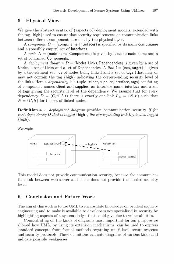
Towards Development of Secure Systems Using UMLsec 197
5 Physical View
We give the abstract syntax of (aspects of) deployment models, extended withthe tag {high} used to ensure that security requirements on communication linksbetween different components are met by the physical layer.
A component C = (comp name, Interfaces) is specified by its name comp nameand a (possibly empty) set of Interfaces.
A node N = (node name, Components) is given by a name node name and aset of contained Components.
A deployment diagram D = (Nodes, Links, Dependencies) is given by a set ofNodes, a set of Links and a set of Dependencies. A link l = (nds, target) is givenby a two-element set nds of nodes being linked and a set of tags (that may ormay not contain the tag {high} indicating the corresponding security level ofthe link). Here a dependency is a tuple (client, supplier, interface, tags) consistingof component names client and supplier, an interface name interface and a setof tags giving the security level of the dependency. We assume that for everydependency D = (C, S, I, t) there is exactly one link LD = (N, t′) such thatN = {C, S} for the set of linked nodes.
Definition 4 A deployment diagram provides communication security if foreach dependency D that is tagged {high}, the corresponding link LD is also tagged{high}.
Example
browser
get_passwordclient <<high>> webserver
access_control
This model does not provide communication security, because the communica-tion link between web-server and client does not provide the needed securitylevel.
6 Conclusion and Future Work
The aim of this work is to use UML to encapsulate knowledge on prudent securityengineering and to make it available to developers not specialised in security byhighlighting aspects of a system design that could give rise to vulnerabilities.
Concentrating on the kinds of diagrams most important for our purpose weshowed how UML, by using its extension mechanisms, can be used to expressstandard concepts from formal methods regarding multi-level secure systemsand security protocols. These definitions evaluate diagrams of various kinds andindicate possible weaknesses.
198 J. Jurjens
In absence of a general formal semantics we use a specifically defined onewhich covers the aspects needed and to the required degree of detail. It is not areplacement for a general formal semantics but rather exemplifies the need forone.
In further work [Jur01a], we have used UMLsec to reason about audit-securityin a smart-card based payment scheme.
In future work, we will consider the remaining kinds of diagrams and movecloser to the unabridged standard of UML by bringing in more detail. In par-ticular, we will explore the use of profiles or prefaces [CKM+99]. Also, we willtry to link the various views on a system given by different diagrams to gainadditional information on the system that may be security-relevant. To increaseusability, we will consider how to automatically derive security annotations fromusual modelling information.
To enable tool support, we aim to find efficiently checkable conditions equiv-alent to the ones given here and to give proof-techniques.
Further case-studies are planned, e. g. regarding development of multilateralsecurity platforms such as [PSW+98].
Acknowledgements. This idea for this work arose when doing security con-sulting for a project lead by S. Nagaraswany during a research visit with M.Abadi at Bell Labs (Lucent Tech.), Palo Alto, whose hospitality is gratefullyacknowledged. This work was presented at the summer school “Foundationsof Security Analysis and Design 2000” (Bertinoro), the Computing Laboratoryat the University of Oxford, the Department of Computer Science at the TUMunchen, and the Department of Computer Science at the TU Dresden. Com-ments from S. Abramsky, C. Bolton, M. Broy, J. Davis, G. Lowe, H. Muccini, G.Wimmel, the anonymous referees, and especially A. Pfitzmann, B. Rumpe andP. Stevens are gratefully acknowledged.
References
[Aba00] M. Abadi. Security protocols and their properties. In F.L. Bauer andR. Steinbrueggen, editors, Foundations of Secure Computation, pages 39–60. IOS Press, 2000. 20th Int. Summer School, Marktoberdorf, Germany.
[AJ00] M. Abadi and Jan Jurjens. Formal eavesdropping and its computationalinterpretation, 2000. submitted.
[And94] R. Anderson. Why cryptosystems fail. Communications of the ACM,37(11):32–40, November 1994.
[APS99] V. Apostolopoulos, V. Peris, and D. Saha. Transport layer security: Howmuch does it really cost ? In Conference on Computer Communications(IEEE Infocom), New York, March 1999.
[AR00] E. Astesiano and G. Reggio. Formalism and method, 2000. to appear inTheoretical Computer Science.
[BAN89] M. Burrows, M. Abadi, and R. Needham. A logic of authentication. Pro-ceedings of the Royal Society of London A, 426:233–271, 1989.
[BD00] C. Bolton and J. Davies. Using relational and behavioural semantics inthe verification of object models. In C. Talcott and S. Smith, editors,Proceedings of FMOODS. Kluwer, 2000.
Towards Development of Secure Systems Using UMLsec 199
[BGH+98] R. Breu, R. Grosu, F. Huber, B. Rumpe, and W. Schwerin. Systems,views and models of UML. In M. Schader and A. Korthaus, editors, TheUnified Modeling Language, Technical Aspects and Applications, pages 93–109. Physica Verlag, Heidelberg, 1998.
[BS00] M. Broy and K. Stølen. Specification and Development of InteractiveSystems. Springer, 2000. (to be published).
[CKM+99] S. Cook, A. Kleppe, R. Mitchell, B. Rumpe, J. Warmer, and A. Wills.Defining UML family members using prefaces. In Ch. Mingins andB. Meyer, editors, TOOLS’99 Pacific. IEEE Computer Society, 1999.
[DS00] P. Devanbu and S. Stubblebine. Software engineering for security: aroadmap. In The Future of Software Engineering, 2000. Special Volume(ICSE 2000).
[EFLR99] A. Evans, R. France, K. Lano, and B. Rumpe. The UML as a formalmodeling notation. In J. Bezivin and P.-A. Muller, editors, The UnifiedModeling Language - Workshop UML’98: Beyond the Notation, LNCS.Springer, 1999.
[For99] UML Revision Task Force. OMG UML Specification 1.3. Available athttp : //www.omg.org/uml, 1999.
[GM82] J. Goguen and J. Meseguer. Security policies and security models. InSymposium on Security and Privacy, pages 11–20. IEEE Computer Soci-ety, 1982.
[GPP98] M. Gogolla and F. Parisi-Presicce. State diagrams in UML: A for-mal semantics using graph transformations. In M. Broy, D. Coleman,T. Maibaum, and B. Rumpe, editors, PSMT’98. TU Munchen, TUM-I9803, 1998.
[Huß99] H. Hußmann. Formale Beschreibungstechniken und praktische Soft-waretechnik – eine ungluckliche Verbindung ? In K. Spies and B. Schatz,editors, Formale Beschreibungstechniken ’99, pages 1–6. Herbert Utz Ver-lag, 1999.
[IT95] ITU-T. Z.120 B – Message Sequence Chart Algebraic Semantics. ITU-T,Geneva, 1995.
[Jur00] Jan Jurjens. Secure information flow for concurrent processes. InC. Palamidessi, editor, CONCUR 2000 (11th International Conferenceon Concurrency Theory), volume 1877 of LNCS, pages 395–409, Pennsyl-vania, 2000. Springer.
[Jur01a] Jan Jurjens. Object-oriented modelling of audit security – a smart-cardcase study. 2001. submitted.
[Jur01b] Jan Jurjens. Principles of Secure Systems Design. PhD thesis, OxfordUniversity Computing Laboratory, 2001. in preparation.
[Jur01c] Jan Jurjens. Secrecy-preserving refinement. In J. Fiadeiro and P. Zave,editors, Formal Methods Europe, LNCS. Springer, 2001. to be published.
[Low96] G. Lowe. Breaking and fixing the Needham-Schroeder Public-Key Proto-col using FDR. In Margaria and Steffen, editors, TACAS, volume 1055 ofLNCS, pages 147–166. Springer, 1996.
[Ove00] G. Overgaard. Formal specification of object-oriented meta-modelling. InFASE2000, volume 1783 of LNCS. Springer, 2000.
[PSW+98] A. Pfitzmann, A. Schill, A. Westfeld, G. Wicke, G. Wolf, and J. Zollner.A Java-based distributed platform for multilateral security. In IFIP/GIWorking Conference ”Trends in Electronic Commerce”, volume 1402 ofLNCS, pages 52–64. Springer, 1998.

200 J. Jurjens
[RACH00] G. Reggio, E. Astesiano, C. Choppy, and H. Hußmann. Analysing UMLactive classes and associated state machines – A lightweight formal ap-proach. In FASE2000, volume 1783 of LNCS. Springer, 2000.
[RCA00] G. Reggio, M. Cerioli, and E. Astesiano. An algebraic semantics of UMLsupporting its multiview approach. In D. Heylen, A. Nijholt, and G. Scollo,editors, AMiLP 2000, 2000.
[RJB99] J. Rumbaugh, I. Jacobson, and G. Booch. The Unified Modeling LanguageReference Manual. Addison-Wesley, 1999.
[RWW94] A. Roscoe, J. Woodcock, and L. Wulf. Non-interference through deter-minism. In ESORICS 94, volume 875 of LNCS. Springer, 1994.
[SP00] P. Stevens and R. Pooley. Using UML. Addison-Wesley, 2000.
Grammar Testing
Ralf Lammel
CWI, Kruislaan 413, NL-1098 SJ AmsterdamVrije Universiteit, De Boelelaan 1081a, NL-1081 HV Amsterdam
Email: [email protected]: http://www.cwi.nl/˜ralf/
Abstract. Grammar testing is discussed in the context of grammar en-gineering (i.e., software engineering for grammars). We propose a gen-eralisation of the known rule coverage for grammars, that is, context-dependent branch coverage. We investigate grammar testing, especiallycoverage analysis, test set generation, and integration of testing andgrammar transformations. Grammar recovery is chosen as a subfield ofgrammar engineering to illustrate the developed concepts. Grammar re-covery is concerned with the derivation of a language’s grammar fromsome available resource such as a semi-formal language reference.
1 IntroductionGrammar engineering. Grammars are omnipresent in software development.They are used for the definition of syntax, exchange formats and others. Sev-eral important kinds of software rely on grammars, e.g., compilers, debuggers,profilers, slicing tools, pretty printers, (re-) documentation tools, language ref-erence manuals, browsers and IDEs, software analysis tools, code preprocessingtools, and software modification tools. The common practice of grammar de-velopment does not quite reflect this importance of grammars. In practice, themost important property of a grammar is to be implementable with a certaintool (e.g., YACC). This focus leads to what we call “grammar hacking”, whereissues like testing and disciplined adaptation of grammars play a minor role.Companies, which crucially rely on grammars, suffer from this lack of engineer-ing discipline. Grammar hacking now sees a renaissance in the XML-age. Wetake a different point of view: Grammars are regarded as proper software en-gineering artifacts (cf. [15,3,12,5] for a similar attitude). We envision grammarengineering, where the development, the maintenance, the recovery, and the im-plementation of grammars are based on well-founded concepts. The technique ofgeneralised LR-parsing [14] (as opposed to LALR(1)), for example, covers the fullclass of context-free grammars. Thereby, it enables a declarative style of gram-mar specification, and it removes the gap between specification and (YACC-)implementation. Thus, generalised LR-parsing facilitates the method of modularsyntax definition because the absence of grammar class restrictions allows us totake unions of grammar modules.
Grammar testing. There are several concepts which contribute to grammar en-gineering. Not all of them have been sufficiently covered in the literature or
H. Hussmann (Ed.): FASE 2001, LNCS 2029, pp. 201–216, 2001.c© Springer-Verlag Berlin Heidelberg 2001
202 R. Lammel
adopted as common practice. Fields of grammar engineering which are mean-while reasonably understood are, for example, grammar implementation andgrammar reengineering [15]. Fields which lack fundamental underpinnings aregrammar adaptation, grammar maintenance, grammar recovery, and grammartesting. The present paper is concerned with grammar testing. From a softwareengineering perspective, grammars are specifications (describing languages), orprograms (serving as compiler compiler input and others). Testing is one stan-dard way to validate specifications or programs (formal analysis is another). Theapproach to grammar testing described in the sequel covers various technical andpragmatic aspects such as coverage notions, test set generation, correctness andcompleteness claims for grammars or parsers, and integration of testing andgrammar transformations.
Structure of the paper. In Section 2, the contributions of the paper are motivatedby a subfield of grammar engineering, namely grammar recovery. In the twosubsequent technical sections, grammar recovery serves for illustrative purposes.In Section 3, the notion of context-dependent branch-coverage is developed. Itimproves on the previously known notion of rule coverage. In Section 4, derivedconcepts for grammar testing are discussed, e.g., automated coverage analysisand test set generation. In Section 5, the paper is concluded.
Acknowledgement. This work was supported, in part, by NWO, in the project“Generation of Program Transformation Systems”. I am grateful for the com-ments by the FASE’01 anonymous referees. I am also grateful to Jeremy Gibbons,Jorg Harm, Jan Heering, Paul Klint, Chris Verhoef and Dave Wile for encour-aging discussions, and for helpful suggestions. Some results from the presentpaper have been presented at the 54th IFIP WG2.1 (“Algorithmic Languagesand Calculi”) meeting in Blackheath, London, April, 3th–7th, 2000, and at the2nd Workshop Software-Reengineering, Bad Honnef, May, 11th–12th, 2000.
2 Motivation: Grammar Recovery
The following discussion of grammar recovery motivates grammar testing andother grammar engineering concepts. Grammar recovery comprises the conceptsinvolved in the derivation of a language’s grammar from some available resourcelike a language reference, or compiler source code. In [12], a more general accounton grammar recovery is given.
2.1 One Scenario
There are several sensible scenarios for grammar recovery. In the present paper,we restrict ourselves to the scenario characterised as follows.
Lack of an approved grammar for a language L. If we want to renovate code insome language L, e.g., in a dialect of an ancient language like COBOL, a suitablegrammar is a pre-condition for certain forms of tool support, e.g., grammar-basedsoftware modification tools. The compiler vendor might not provide us with thegrammar for the language, or the sources for the compiler. Also, the sources
Grammar Testing 203
might not be immediately useful for an extraction of the grammar, e.g., in thecase of manually implemented frontends. It is also conceivable that the compilersource code and the vendor are not accessible altogether.
Approximative grammar γ0 for the intended language L. We assume that thereis an approximative grammar γ0 for L. The grammar could be obtained froma semi-formal language reference, or some grammar-based tool the sources ofwhich are available. By approximative we mean that we accept that γ0 is proba-bly incomplete and incorrect w.r.t. L to a certain extent. This is the challengingaspect of the scenario. Thereby, grammar recovery goes beyond grammar reengi-neering in the narrow sense, where one is merely concerned with the extractionof the base-line grammar from the sources of a reference implementation, andits refactoring [15]. Let us define the terms incorrectness and incompleteness.
Definition 1. A grammar G is incorrect w.r.t. an (intended) language L, ifL 6⊇ L(G). Here, L(G) denotes the language generated by G, i.e., all terminalstrings derivable from the start symbol of G. The grammar G is incomplete w.r.t.L if L 6⊆ L(G).
The definition is inspired by a point of view as favoured in the diagnosis of logicprograms (cf. [6]). The problem with the definition is that the intended languageL is not directly accessible. Also, we need to know how to locate incorrect orincomplete phrases in the grammar, and how to correct and complete them.Finally, incorrectness and incompleteness are intertwined. An incorrect phraseoften causes some incompleteness. Correcting the phrase also contributes to thecompletion of the grammar. We should point out that our model of correct andcomplete grammars is a bit naive (for brevity). In practice, one has usually toconsider correctness and completeness of parsers. Thereby, further requirementsmight be implied, e.g., suitable and correct parse trees, grammar class restric-tions, disambiguation, and others.
Representative trusted test set C written in L. By trusted we mean that thecode base C is known to comply with L because it is accepted by a referenceimplementation I such as a parser or a compiler for L. Note that we do notnecessarily need I physically. It might also be sufficient if C was approved bysomeone else who applied I, or by the corresponding standardisation board, orby the compiler vendor. Besides legal issues, it is not clear if re-compilation isa valid option in order to obtain a useful grammar from a compiler or anotherlanguage implementation, if it is only available in binary form. By representativewe mean that C should be large enough to experience all possible constructs ofthe intended language L in some sense.
Derivation of a relatively complete and correct grammar γn for L. The overallidea is to parse more and more programs from C, and to resolve the upcom-ing incompleteness problems indicated by failure of parsing by specific grammartransformations, e.g., by generalising phrases in the grammar accordingly. Dueto the intertwined character of incompleteness and incorrectness, the correctnesswill also be improved in that process because usually the grammar is modified
204 R. Lammel
and not just extended. This stepwise process which results in intermediate gram-mars γ1, γ2, . . . is stopped with γn if C has been parsed. In each step, a grammartransformation ti is used to address a particular error or omission. Since we con-sider γ0 as an approximation of L, the structure of γ0 should be preserved in γn
as much as possible.
2.2 Case Study
We use VS COBOL II as case study. Its grammar was recovered from IBM’sreference [10]. As for the test set involved in the project, 2 millions lines ofcode from several software projects were used. The raw grammar extracted fromIBM’s reference was corrected and completed by about 300 small transformationsteps. The recovered grammar has been published in December 1999 [11]. It isused by COBOL practioners, tool developers, compiler writers and others sincethen. The grammar is the first publically available quality COBOL grammar.It was obtained in just a few weeks based on a reproducable process for gram-mar recovery described in [12]. This figure is in strong contrast to other knownfigures for (unpublished) quality COBOL grammars. It takes some engineeringknowledge or a lot of money to come up with good grammars.
From diagrams to the raw grammar. The IBM reference contains large portionsof the VS COBOL II syntax in a graphical notation of so-called syntax diagrams.Some diagrams are not even syntactically correct in the sense of the underlyingdiagram notation. Other diagrams are semantically incorrect in the sense thatthey do not generate the intended language. Many diagrams are not correctand complete in the sense that the reference uses informal notes to relax or torestrict the diagrams. Using a dedicated parser for syntax diagrams, the rawVS COBOL II grammar was extracted from the reference. This raw grammarprovides the initial and approximative grammar γ0 according to the scenariosketched above. A fragment of the raw VS COBOL II grammar is shown inFig. 1 using extended BNF notation.
Data-description-entry =Level-number (Data-name | "FILLER")? Redefines-clause?Blank-when-zero-clause? External-clause? Global-clause?Justified-clause? Occurs-clause? Picture-clause? Sign-clause?Synchronized-clause? Usage-clause? Value-clause?
Redefines-clause =Level-number (Data-name | "FILLER")? "REDEFINES" Data-name
Fig. 1. Fragment of raw grammar extracted from [10]
Incorrectness. The fragment in Fig. 1 provides a good example for an incor-rectness of the raw extracted grammar. The format of Redefines-clause doesactually cover more than just the structure of the clause itself. We might assumethat the correction is performed by a grammar transformation which simply
Grammar Testing 205
deletes the obsolete part of the incorrect definition from the raw grammar. Theproper definition Redefines-clause is the following:
Redefines-clause = "REDEFINES" Data-name
Error detection by parsing. In general, an incorrectness might go undetectedif only parsing is used for diagnosis because incorrectness means that the lan-guage generated by a grammar contains words which are not contained in theintended language. The above incorrectness (and many others) will be realisedwhen approved code is parsed, if the code experiences Redefines-clause. Thisis implied by the intertwined character of incorrectness and incompleteness. Theincorrect definition of Redefines-clause is in conflict with the correct form.
Incompleteness. The most basic form of incompleteness is that some nontermi-nals are not defined altogether. This form of incompleteness can be recognizedstatically. Otherwise, incompleteness means that certain phrases in the gram-mar are too restricted, i.e., they do not cover the corresponding construct in fullgenerality. This form of incompleteness can be uncovered by parsing if the testset experiences the corresponding construct as assumed for a representative testset. The IBM reference, for example, contains an informal note that the orderof the clauses in a data description entry is immaterial. In fact, actual COBOLcode experiences different orders. The sequence of clauses in Fig. 1 should beturned into a permutation phrase.
2.3 Challenges
There are certain questions the answers to which affect the process of grammarrecovery in an essential manner. How do we assess the quality of the code baseC? How do we precisely know that C is representative? What does it mean forγn to be complete and correct? A completeness relative to C can be claimed ifC ⊆ L(γn), that is, if C can be parsed. According to Definition 1, correctnessin a narrow sense means that L ⊇ L(γn). However, L is not directly accessible.So what is a realistic requirement for the relative correctness of γn? Besidescompleteness and correctness of γn, what is the relationship between γ0 andγn? The latter question is concerned with the stepwise process of correction andcompletion. In general, we might ask what kind of properties can be requiredfor the transformations ti for the steps. What does it mean for ti to correct orto complete resp. the grammar?
In order to answer these questions thoroughly, concepts for testing grammarsare worked out in the following two sections. These concepts are not only use-ful for grammar recovery but also for other grammar-dependent problems, e.g.,parser testing, grammar maintenance, and automated software modification.
3 Context-Dependent Branch Coverage
We discuss the notion of context-dependent branch coverage obtained as an es-sential generalisation of rule coverage [13]. Firstly, rule coverage will be revisited.Secondly, a context-dependent generalisation is developed. Finally, the use ofthe coverage notion is illustrated in grammar recovery.
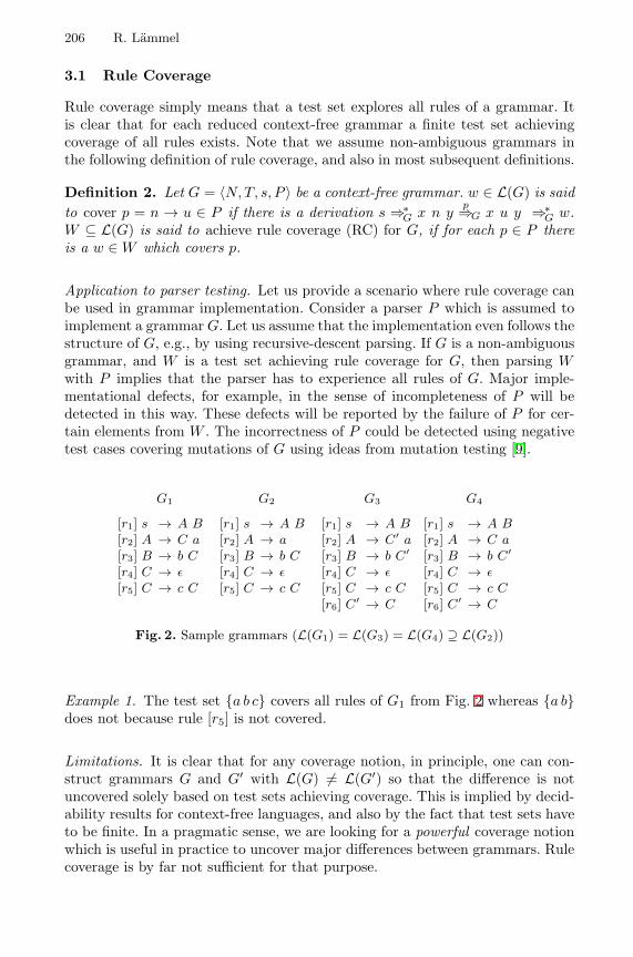
206 R. Lammel
3.1 Rule Coverage
Rule coverage simply means that a test set explores all rules of a grammar. Itis clear that for each reduced context-free grammar a finite test set achievingcoverage of all rules exists. Note that we assume non-ambiguous grammars inthe following definition of rule coverage, and also in most subsequent definitions.
Definition 2. Let G = 〈N, T, s, P 〉 be a context-free grammar. w ∈ L(G) is saidto cover p = n → u ∈ P if there is a derivation s ⇒∗
G x n yp⇒G x u y ⇒∗
G w.W ⊆ L(G) is said to achieve rule coverage (RC) for G, if for each p ∈ P thereis a w ∈ W which covers p.
Application to parser testing. Let us provide a scenario where rule coverage canbe used in grammar implementation. Consider a parser P which is assumed toimplement a grammar G. Let us assume that the implementation even follows thestructure of G, e.g., by using recursive-descent parsing. If G is a non-ambiguousgrammar, and W is a test set achieving rule coverage for G, then parsing Wwith P implies that the parser has to experience all rules of G. Major imple-mentational defects, for example, in the sense of incompleteness of P will bedetected in this way. These defects will be reported by the failure of P for cer-tain elements from W . The incorrectness of P could be detected using negativetest cases covering mutations of G using ideas from mutation testing [9].
G1
[r1] s → A B[r2] A → C a[r3] B → b C[r4] C → ε[r5] C → c C
G2
[r1] s → A B[r2] A → a[r3] B → b C[r4] C → ε[r5] C → c C
G3
[r1] s → A B[r2] A → C′ a[r3] B → b C′
[r4] C → ε[r5] C → c C[r6] C′ → C
G4
[r1] s → A B[r2] A → C a[r3] B → b C′
[r4] C → ε[r5] C → c C[r6] C′ → C
Fig. 2. Sample grammars (L(G1) = L(G3) = L(G4) ⊇ L(G2))
Example 1. The test set {a b c} covers all rules of G1 from Fig. 2 whereas {a b}does not because rule [r5] is not covered.
Limitations. It is clear that for any coverage notion, in principle, one can con-struct grammars G and G′ with L(G) 6= L(G′) so that the difference is notuncovered solely based on test sets achieving coverage. This is implied by decid-ability results for context-free languages, and also by the fact that test sets haveto be finite. In a pragmatic sense, we are looking for a powerful coverage notionwhich is useful in practice to uncover major differences between grammars. Rulecoverage is by far not sufficient for that purpose.
Grammar Testing 207
Example 2. G1 and G2 from Fig. 2 do not generate the same language becauseG2 lacks the occurrence of C in [r2]. Note that L(G1) ⊃ L(G2) because ε isderivable from C. The set {a b c} covers all rules of G1 and G2. Thus, rulecoverage does not uncover the incompleteness of G2 w.r.t. G1.
Let us rephrase the above example in the context of parser testing. Suppose,G1 serves as specification, but an actual parser accidentally implements G2. Atest set achieving rule coverage for the specification G1 does not necessarilyuncover the incompleteness of the parser implementing G2. Any testing methodas opposed to formal verification is limited in the sense that errors can onlybe found to a certain extent. The above example illustrates that rule coverageexplores a grammar’s structure in a rather weak sense.
3.2 Context-Dependent Rule Coverage
We propose a generalisation of rule coverage, where the context in which a ruleis covered is taken into account. This idea is easy to formalise.
Definition 3. Let G = 〈N, T, s, P 〉 be a context-free grammar. If m → u n v ∈P , where m, n ∈ N , u, v ∈ (N∪T )?, then m → u n v is called direct occurrenceof n in G. Occs(G, n) denotes the set of all direct occurrences of n in G.
Example 3. All direct occurrences of G1 from Fig. 2 are listed:
Occs(G1, s) = ∅Occs(G1, A) = {[r1] s → A B}Occs(G1, B) = {[r1] s → A B }Occs(G1, C) = {[r2] A → C a, [r3] B → b C , [r5] C → c C }
Definition 4. Let G = 〈N, T, s, P 〉 be a context-free grammar. w ∈ L(G) issaid to cover the rule p = n → z ∈ P for the occurrence m → u n v ifthere is a derivation s ⇒∗
G x m yq⇒G x u n v y
p⇒G x u z v y ⇒∗G w with
q = m → u n v ∈ P . W ⊆ L(G) is said to cover p = n → z ∈ P for alloccurrences, if there is a w ∈ W for all occurrences o ∈ Occs(G, n) such that wcovers p for o. W is said to achieve context-dependent rule coverage (CDRC)for G, if W covers all p ∈ P for all occurrences.
Example 4. CDRC separates the grammars G1 and G2 from Fig. 2. Every test setW achieving CDRC for G1, e.g., W = {a b, c c a b c} must explore both rules forC in all occurrences of C. Thus, the incompleteness of G2 w.r.t. G1 is uncovered.
Theorem 1. For all reduced context-free grammars G = 〈N, T, s, P 〉, if Wachieves context-dependent rule coverage of G, then W also achieves rule cov-erage of G provided the following side condition holds: Occs(G, s) 6= ∅, or s isdefined by a single rule.
208 R. Lammel
Proof. In a reduced context-free grammar, each rule n → z ∈ P with n 6= s hasat least one occurrence. Thereby, the rule is covered per pre-condition (for evenall occurrences). If s is defined by a single rule, this rule will be covered sincederivation starts from s. Otherwise, per side condition we know that there areoccurrences of s. Then, the rules defining s are covered like all other rules.
Sensitivity. There is a problem with the context-dependent coverage notion as itstands now. The given definition is very sensitive to chain rules and fold/unfoldmanipulations. These concepts are useful to improve the structure of a givengrammar. By sensitivity we mean that the fact if a test set achieves coverageor not is dependent on the existence of chain rules, and it varies for grammarswhich are equivalent modulo fold/unfold manipulations. First, we identify somerelevant terms. Then, we indicate a solution for the sensitivity problem.
Definition 5. The nonterminal n is said to be non-branching in a context-freegrammar G if there is exactly one defining rule for n in G. NB(G) denotes theset of non-branching nonterminals in G. A rule is said to be an injection, if itis of the form n → n′, where both n and n′ are nonterminals. A rule is said tobe a chain rule, if it is an injection, and the nonterminal on the left-hand sideis non-branching.
Example 5. Although L(G1) = L(G3) = L(G4), CDRC of G3 can already beachieved with W = {a b c c} whereas W is not sufficient for G1 and G4. Thethree grammars are structurally equivalent under chain rule elimination. G1 doesnot contain chain rules. G3 and G4 contain the chain rule [r6] C ′ → C. Notethat we can also understand the structural differences between the grammars interms of fold/unfold manipulations. Coverage for G3 does not imply that therules defining C are covered for the two occurrences of C ′. Therefore, coverageis easier to achieve for G3. The chain rule in G4 does not affect coverage becauseC ′ has only one occurrence, and thus the rules for C will be exhausted via thedefinition of C ′.
The sensitivity of context-dependent rule coverage can be decreased considerably,if non-branching nonterminals are handled in a special way. We can considerindirect occurrences as opposed to direct occurrences in Definition 3 where rulesof non-branching nonterminals are involved for intermediate derivation steps. Weuse sequences of direct occurrences in order to represent indirect occurrences.
Definition 6. Let G be a context-free grammar. The sequence of direct occur-rences 〈n0 → u1 n1 v1, . . . , nm−1 → um nm vm, 〉 for m > 1 is called indirectoccurrence of nm in G reachable via M ⊆ N if n1, . . . , nm−1 ∈ M , and n1, . . . ,nm are pairwise distinct.
We can update the notation Occs(G, n) to refer to both direct and indirectoccurrences. Definition 4 is also easy to generalise. We use CDRCM to denote therefinement of CDRC to take indirect occurrences reachable via M into account.The described sensitivity problem is solved if NB(G) is chosen for M .
Grammar Testing 209
Example 6. Recall the problem from Example 5. The set {a b c c} is not sufficientto achieve CDRC∗ for G3, although it was sufficient to achieve CDRC.
Note that the simple CDRC is harder to achieve, if non-branching nonterminalsare eliminated before coverage is considered. As for chain rules, this normali-sation corresponds to chain rule elimination being one of the steps involved inthe folklore algorithm for obtaining Chomsky Normal Form. For more generalnon-branching nonterminals, a simple unfold step is usually sufficient. The rea-son why we do not attempt such a normalisation is that we want to considercoverage of the original grammar. If some rule is not experienced in a certaincontext, for example, then, for traceability, the corresponding analysis shouldrefer to the original grammar rather than to a normalised grammar.
Both rule coverage and the context-dependent generalisation of it were statedfor pure context-free grammars, that is, basic BNF notation. Often extendedBNF (EBNF) notation is used. One way to look at EBNF is that other constructsfor branching than just multiple rules for a nonterminal are provided. In thissense, we are looking for slight generalisations of the defined coverage notions,namely branch coverage and the context-dependent generalisation (CDBC) ofit. We do not work out these generalisations in the present paper.
3.3 Application to Grammar Recovery
Recall the scenario for grammar recovery from Section 2.2. It is instructive tonotice that an uncovered part of an intermediate grammar γi, which acceptssome code base C ′ available at this point in the process, provides an indicationof either insufficiency of C ′ or incorrectness of γi. If full coverage is achieved, wemight claim that both the ultimate C has been accumulated, and a correct andcomplete γn has been found. In practice, it is difficult to accumulate a code basewhich achieves full coverage, at least for a challenging criterion like CDBC. Thus,in a sense the quality of the code base C ′ and correctness of γi are measured inan intertwined manner.
The value of CDBC. The non-trivial coverage notion CDBC as opposed to sim-ple rule coverage adds precision. Consider, for example, the following three rulesA → B, A → C, and A → D defining A. If in some occurrence, A is used whereB, C or D is intended instead, a trusted test set cannot cover the correspondingoccurrence. Let us consider an example from the VS COBOL II recovery project.In COBOL, data names can be qualified for nested group fields (records). More-over, a qualification with a file name can be performed. Thus, we have thefollowing syntax:
qualified-data-name =data-name (("IN"|"OF") data-name)* (("IN"|"OF") file-name)?
IBM’s reference for VS COBOL II is imprecise about where non-qualified asopposed to qualified data names are to be used. A decent test set will un-cover if data-name is too specific for some occurrence. CDBC prevents us fromgeneralising the occurrences of data-name more than intended.
210 R. Lammel
4 Grammar Testing
Based on the basic notion of context-dependent coverage introduced in the previ-ous section, further concepts for grammar testing can be supplied. In this section,coverage analysis, test set generation, and integration of testing and transforma-tion are discussed. We want to mention that these concepts for grammar testingare certainly also useful for other formalisms than grammars. We can think of,for example, signatures, algebraic data types, or document type definitions inthe XML context.
4.1 Coverage Analysis
Given a test set W and a grammar G, a coverage analyser is supposed to returnsome representation of the coverage of G by W . As for CDBC, we are interestedin the branches which are (not) covered for certain occurrences. We will work outthe idea of coverage analysis for basic BNF and direct occurrences. As for therepresentation of coverage, we assume that the coverage of G by W correspondsto a subset of the full coverage set defined as follows.
Definition 7. Given a context-free grammar G = 〈N, T, s, P 〉, the full coverageset FCS(G) for G is the following:
FCS(G) ={
〈p, o〉∣∣∣∣ p ∈ P,
o ∈ Occs(G, n),where p is of the form n → u
}
Derivation of coverage analysers. We use attribute grammars to formalise cover-age analysers. Actually, a scheme to derive an attribute grammar CA(G) imple-menting the coverage analyser for G is supplied. Essentially, CA(G) synthesizesa coverage set from a given test set W . Therefore, W is parsed as a list byCA(G). The context-free grammar underlying CA(G) is essentially G but witha new start symbol s′ to model lists of words in the sense of G:
〈N ∪ {s′}, T, s′, P ∪ {s′ → ε, s′ → s s′}〉
We want to synthesize an attribute c for all non-terminals to capture the coverageof G by the parsed test set. All nonterminals n (but s′) carry an inheritedattribute o of type Occs(G, n) where we consider a special value 2 to encode thetop level application of rules for s. The following computations are associatedwith the rules defining the new start symbol s′.
s′ → εs′.c := ∅
s′0 → s s′
1s.o := 2
s′0.c := s.c ∪ s′
1.c
Their interpretation is straightforward. The coverage of the empty list is the“empty coverage”, whereas the coverage of a non-empty list is obtained by takingthe union of head’s and tail’s coverage. The computation for the rules in P follow
Grammar Testing 211
a common scheme. Given a rule p ∈ P with p = l → x1 · · · xn and l ∈ N ,xi ∈ N ∪ T for i = 1, . . . , n, the following computations are associated with p:
xi1 .o := l → x1 · · ·xi1−1 xi1 xi1+1 · · ·xn
· · ·xim
.o := l → x1 · · ·xim−1 ximxim+1 · · ·xn
l.c := xi1 .c ∪ · · · ∪ xim.c ∪ {〈p, l.o〉}
The xi1 , . . . , xim correspond to the nonterminals on the right-hand side of p. Theintention of the computations is simply to propagate the actual occurrence andto combine coverage from all the nonterminals on the right side of a rule whileadding the coverage of the particular rule for the inherited occurrence.
Example 7. CA(G1) (refer to Fig. 2 for G1) synthesizes a coverage for a b andc a b c, where only the element 〈C → c C, C → c C 〉 is missing from the fullcoverage set FCS(G1). Thus, the rule C → c C has not been used for therecursive occurrence of C in C → c C.
There are two useful refinements of the above scheme. Firstly, one can countactual applications of rules for the various occurrences. For that purpose, it issufficient to allow the attributes c to carry multi-sets. Secondly, CDRCM can beaccomplished by propagating indirect occurrences with the attributes o.
4.2 Test Set Generation
A test set generator is a program which computes a test set achieving the desiredcoverage criterion. Test set generation is useful, for example, in language design,and parser testing. Returning to the application scenario of parser testing inSection 3.1, test set generation automates testing the parser P w.r.t. a referencegrammar G.
The generative application of context-free grammars is reasonably under-stood. Some fundamental algorithms are developed in [13], e.g., shortest deriva-tions to reach a certain nonterminal, and the derivation of tests sets achievingrule coverage. One approach to test set generation is the following. Given acontext-free rule, a shortest completion is computed. Thereby, it is possible tocompute a small test set of words with short derivations achieving rule coverage.When grammars are applied for the syntax definition of languages, the choice ofshortest completions is beneficial for debugging purposes. One can also favouran even smaller test set of words with longer derivations to cover as many rulesin one derivation as possible. The context-dependent generalisation of rule cov-erage does not introduce any complication: Rules occurring in certain contextsare completed instead of just rules.
4.3 Integration with Transformation
Grammars need to be adapted during recovery, maintenance, and elsewhere.Grammar transformations are useful for an operational and formal model of cor-responding adaptations. We separate grammar refactorings which do not change
212 R. Lammel
the generated language, and transformations for construction and destructionwhich go beyond simple semantics-preserving transformations (in terms of thegenerated language). An application scenario for grammar refactoring is DeY-ACCification and modularisation which are useful in grammar reengineering inorder to go from YACC-like pure BNF notation to a richer notation (cf. [15])including constructs for extended BNF and modules as, for example, in SDF[8]. The steps to correct or to complete a grammar in grammar recovery can bemodelled by constructing or destructing transformations. We want to study therelation between grammar transformations and grammar testing.
An operator suite. Let G denote the set of all context-free grammars. Then, agrammar transformation is a partial function on G. Partial functions have to beconsidered because of applicability conditions. The operators are explained bydescribing their effect on an input grammar G = 〈N, T, s, P 〉. Some transforma-tions are applied in a focus F ⊆ N , that is, the transformations are supposedto affect only the definitions of nonterminals F . There are the following opera-tors. introduce n as u adds the rule n → u to G. The operator is applicable ifn 6∈ N . fold u to n replaces the phrase u ∈ (N ∪ T )? in the rules defining F byn, e.g., n′ → x u y is turned into n′ → x n y. The operator is applicable if n isa non-branching nonterminal defined by the rule n → u. unfold n replaces theright-hand side occurrences of the nonterminal n in the rules defining F by thedefinition of n, e.g., n′ → x n y is turned into n′ → x u y if G contains the rulen → u. The operator is applicable if n is non-branching in P . eliminate n removesall rules defining the nonterminal n from G. The operator is applicable if n is notreachable from s. The operators for introduction, folding, unfolding, and elimi-nation facilitate grammar refactoring without changing the generated language.The remaining two operators are constructive or destructive resp. in the sensethat they increase and decrease of the generated language. include u for n addsthe rule n → u to G. The operator is applicable if n is defined in G, that is, thereis at least one rule with n on the left-hand side in G. exclude u from n removesthe rule n → u from G. The operator is applicable if there are two or more rulesdefining n, one of the form n → u.
Coverage-related relations on grammars. The impact of grammar transforma-tions regarding coverage can be conceived in terms of some relations on gram-mars, e.g., the property if two grammars are covered by the same test sets.
Definition 8. We use R(G) to denote the reduced sub-grammar of G which isobtained by removing rules which are not reachable, or which are not terminated.Given two context-free grammars G and G′, and a coverage criterion α, we sayα for G implies α for G′ if for W ⊆ (L(R(G))∩L(R(G′))) holds that W achievesα-coverage for R(G) implies W achieves α-coverage for R(G′). G and G′ arecalled α-equivalent if α for G implies α for G′ and vice versa.
Properties of transformations. Based on the above grammar relations, transfor-mations can be characterised w.r.t. coverage as follows.
Grammar Testing 213
Definition 9. A partial function f : G ◦→ G is said to improve (v.s. hamper) thecoverage criterion α if α for G implies α for f(G) (or vice versa for hampering)for all G ∈ G where f(G) is defined. If G and f(G) are α-equivalent, f is saidto preserve α.
The following theorem states properties of the above operators w.r.t. CDRCM .The overall conclusion is that refactoring of grammars does not cause sensitiv-ity problems for coverage. The constructing and destructing operators hamperor improve resp. coverage, since they are essentially concerned with adding orremoving branches.
Theorem 2.
1. fold u to n and unfold n preserve CDRC∗.2. eliminate n and introduce n as u preserve CDRC and CDRC∗.3. include u for n hampers CDRC and CDRCNB(G)∪{n}.4. exclude u from n improves CDRC and CDRCNB(G)∪{n}.
Proof. (Sketch)1. Direct occurrences become indirect occurrences and vice versa.2. R(·) neutralizes the eliminated / introduced rule.3. The included rule has to be covered for Occs(G, n).4. The excluded rule has not to be covered anymore.
As for the fold operator and the unfold operator, the consideration of CDRC∗, isessential according to the discussion in Section 3.2 (cf. Example 5 in particular).Note that the property of the include operator and the exclude operator tohamper or to improve coverage does not hold for CDRC∗. We indeed have toconsider indirect occurrences reachable via NB(G) ∪ {n} because by includingor excluding a rule the defined nonterminal n might change its status to be anon-branching or a branching nonterminal, respectively.
4.4 Application to Grammar Recovery
Approval of uncovered branches. At any point in the process, coverage analysiscan be used to compute the coverage of γi w.r.t. the currently available andparsed code base C ′. Still there is the problem that uncovered branches (in somecontext) are either an indication of the insufficiency of C ′ or the incorrectness ofγi. Let us assume that a reference implementation I for the intended languageL is available. Test set generation can be used to generate a test set W fromγi. We might prefer to generate only programs which improve on the coverageof C ′. W can be checked if it is contained in the intended language, i.e., if it isparsed by I. Besides the availability of I, the only pre-condition is that the errormessages produced by I are sufficient to separate parsing errors and violationsof static semantics. If W is accepted by I, then the phrases corresponding to allbranches in all contexts are feasible in L. Thereby, we can approve uncoveredbranches without even relying on a code base experiencing them.
214 R. Lammel
Correctness and completeness. The above approach suggests a correctness claimw.r.t. CDBC. If I accepts W , the grammar γn can be said to be correct w.r.t.CDBC. In this claim, C is not involved. By contrast, completeness is relative toC, that is, γn is said to be complete w.r.t. C. In a sense, the ultimate code base Cis more important for completing γ0, whereas test set generation is more relevantto claim correctness of γn. Of course, even if I is available to gain confidencein the correctness of γn by parsing generated test cases, full correctness cannotbe claimed. The property L(γn) ⊆ L cannot be checked by repeatedly applyingI which models membership test for L. For similar reasons, the completenessclaim is inherently relative.
Preservation of structure. Assuming that the extracted raw grammar γ0 is auseful approximation of L, we want to preserve its structure as much as possible.Both destruction and construction, that is, removal and addition of branches,should be defensive. That is enforced if the transformation sequence t1, . . . , tnsatisfies the following requirements:
– Incorrect phrases are removed by destructing transformations.– Missing phrases are added by constructing transformations.– Branches of the grammar which can be covered are not removed.– Added branches are ultimately covered.
The relative completeness and correctness claims for γn are strengthened in thisway because γn can be regarded as a refactored variant of γ0 with some removedand added branches. The removal and the addition of these branches was solelytriggered by C. Context-dependency of coverage is relevant here if branches areto be added or removed only for certain occurrences of a nonterminal.
5 Concluding Remarks
Contribution and applications. Context-dependent branch coverage and derivedconcepts for coverage analysis, test set generation, and the integration of test-ing and transformation were developed. These testing concepts are meant as acontribution to grammar engineering. The paper illustrated that more involvedcoverage criteria than the previously known rule coverage are needed. Our ex-amples were concerned with parser testing and grammar recovery. The papersuggested original relative correctness and completenss claims for parsers andgrammars. Several further applications are conceivable, e.g., language design,and grammar minimalisation for automated software renovation.
Related work. Certain rather pragmatic forms of coverage analysis have beensuggested by others, e.g., in [2], it was suggested to count rule applications for aYACC-grammar. Previous approaches to test set generation (for testing languageprocessors) are based on either rule coverage or randomized test sets (cf. [1]).Burgess [4] compiled a survey on compiler testing. A challenging problem intesting compilers or other language processors is the generation of semanticallycorrect programs. Thereby, generation of test sets and feasibility of coverage is
Grammar Testing 215
considerably more complicated. One can think of coverage in two dimensionsfor the language definitions specified, for exampple, with attribute grammars:a syntactical dimension corresponding to the underlying context-free grammar,and a semantical dimension corresponding to the attributes, their types, and thecomputations associated with the productions. This issue is examined in somedepth in [7] based on a related coverage criterion.
Perspective. We are working on adequate tool support for coverage analysis,coverage visualisation, test set generation, and grammar transformation. Thisproject is challenged by the fact that the tools should scale up for complexgrammars and huge test sets. We would also like to apply our concepts to docu-ment type definitions in the XML context. At the conceptual level, there are thefollowing directions for future work. Our relative notions of grammar correct-ness and completeness can definitely be further improved or complemented. Onewould like to consider metrics, for example, to quantify the structure preserva-tion for the raw grammar γ0. Our relative correctness claim for γn was based onthe generation of positive test cases from the grammar to see if they are parsedby a reference implementation. Dually, we could use negative test cases, whichhad to be refused by the reference implementation, for a stronger completenessclaim. Negative test cases could be obtained via mutation testing [9].
References
1. D. L. Bird and C. U. Munoz. Automatic generation of random self-checking testcases. IBM Systems Journal, 22(3):229–245, 1983.
2. A. Boujarwah and K. Saleh. Compiler test suite: evaluation and use in an auto-mated test environment. Information and Software Technology, 36(10):607–614,1994.
3. M. Brand, M. Sellink, and C. Verhoef. Current parsing techniques in softwarerenovation considered harmful. In S. Tilley and G. Visaggio, editors, Proceedingsof the sixth International Workshop on Program Comprehension, pages 108–117,1998.
4. C. J. Burgess. The Automated Generation of Test Cases for Compilers. SoftwareTesting, Verification and Reliability, 4(2):81–99, jun 1994.
5. M. de Jonge and J. Visser. Grammars as Contracts. In Proc. of GCSE 2000,LNCS, Erfurt, Germany, 2001. Springer-Verlag. to appear.
6. G. Ferrand. The Notions of Symptom and Error in Declarative Diagnosis of LogicPrograms. In P. Fritzon, editor, Automated and Algorithmic Debugging, FirstInternational Workshop, AADEBUG’93, volume 749 of Lecture Notes in ComputerScience, pages 40–57. Springer-Verlag, 3–5 May 1993.
7. J. Harm and R. Lammel. Two-dimensional Approximation Coverage. Informatica,24(3), 2000.
8. J. Heering, P. R. H. Hendriks, P. Klint, and J. Rekers. The syntax definitionformalism SDF — Reference manual. SIGPLAN Notices, 24(11):43–75, 1989.
9. W. E. Howden. Weak mutation testing and completeness of test sets. IEEETransactions on Software Engineering, 8(4):371–379, July 1982.
10. IBM Corporation. VS COBOL II Application Programming Language Reference,1993. Release 4, Document number GC26-4047-07.

216 R. Lammel
11. R. Lammel and C. Verhoef. VS COBOL II Grammar Version 1.0.3.http://www.cwi.nl/˜ralf/grammars, 1999–2001.
12. R. Lammel and C. Verhoef. Semi-automatic Grammar Recovery. Submitted,available at http://www.cwi.nl/˜ ralf/, July 2000.
13. P. Purdom. A sentence generator for testing parsers. BIT, 12(3):366–375, 1972.14. J. Rekers. Parser Generation for Interactive Environments. PhD thesis, University
of Amsterdam, 1992.15. M. Sellink and C. Verhoef. Development, assessment, and reengineering of lan-
guage descriptions. In J. Ebert and C. Verhoef, editors, Proceedings of the FourthEuropean Conference on Software Maintenance and Reengineering, pages 151–160.IEEE Computer Society, March 2000.
Debugging via Run-Time Type Checking
Alexey Loginov, Suan Hsi Yong, Susan Horwitz, and Thomas Reps
Computer Sciences Department, University of Wisconsin-Madison1210 West Dayton Street, Madison, WI 53706 USA
{alexey, suan, horwitz, reps}@cs.wisc.eduFax: (608) 262-9777
Abstract. This paper describes the design and implementation of a toolfor C programs that provides run-time checks based on type information.The tool instruments a program to monitor the type stored in each mem-ory location. Whenever a value is written into a location, the location’srun-time type tag is updated to match the type of the value. Also, thelocation’s static type is compared with the value’s type; if there is a mis-match, a warning message is issued. Whenever the value in a location isused, its run-time type tag is checked, and if the type is inappropriate inthe context in which the value is being used, an error message is issued.The tool has been used to pinpoint the cause of bugs in several Solarisutilities and Olden benchmarks, usually providing information that issuccinct and precise.
1 Introduction
Java programmers have the security of knowing that errors like out-of-boundsarray indexes or attempts to dereference a null pointer will be detected andreported at runtime. Java also provides security via its strong type system. Forexample:
– There are no union types in Java, so it is not possible for a program to writeinto a field of one type and then access that value via a field of a differenttype.
– Only very restricted kinds of casting are allowed; for example, it is not pos-sible to treat a pointer as if it were an integer or vice versa.
– When an object is down-cast to a subtype, a run-time check is performed toensure that the actual type of the object is consistent with the cast.
C and C++ programmers are not so lucky. These languages are more liberalthan Java in what they allow programmers to express; the static type system isweaker; and the run-time system provides little in the way of protection fromerrors caused by misuse of casts, bad pointer dereferences, or array out-of-boundserrors. Programmers can use Purify[1], Safe-C[2], and shadow processing[3] tohelp detect bad memory accesses, but those tools provide no help with the manyadditional kinds of errors that can be introduced into C and C++ programs dueto their weak type systems.
H. Hussmann (Ed.): FASE 2001, LNCS 2029, pp. 217–232, 2001.c© Springer-Verlag Berlin Heidelberg 2001
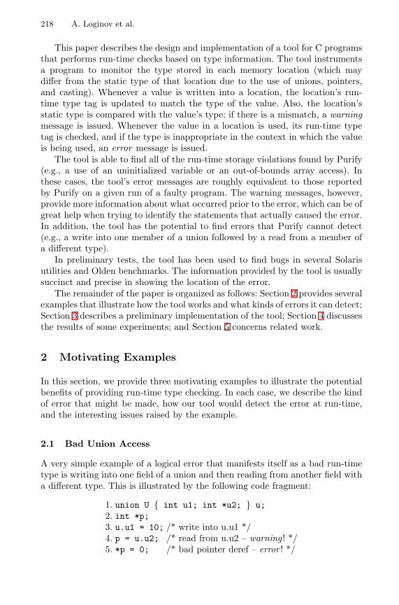
218 A. Loginov et al.
This paper describes the design and implementation of a tool for C programsthat performs run-time checks based on type information. The tool instrumentsa program to monitor the type stored in each memory location (which maydiffer from the static type of that location due to the use of unions, pointers,and casting). Whenever a value is written into a location, the location’s run-time type tag is updated to match the type of the value. Also, the location’sstatic type is compared with the value’s type; if there is a mismatch, a warningmessage is issued. Whenever the value in a location is used, its run-time typetag is checked, and if the type is inappropriate in the context in which the valueis being used, an error message is issued.
The tool is able to find all of the run-time storage violations found by Purify(e.g., a use of an uninitialized variable or an out-of-bounds array access). Inthese cases, the tool’s error messages are roughly equivalent to those reportedby Purify on a given run of a faulty program. The warning messages, however,provide more information about what occurred prior to the error, which can be ofgreat help when trying to identify the statements that actually caused the error.In addition, the tool has the potential to find errors that Purify cannot detect(e.g., a write into one member of a union followed by a read from a member ofa different type).
In preliminary tests, the tool has been used to find bugs in several Solarisutilities and Olden benchmarks. The information provided by the tool is usuallysuccinct and precise in showing the location of the error.
The remainder of the paper is organized as follows: Section 2 provides severalexamples that illustrate how the tool works and what kinds of errors it can detect;Section 3 describes a preliminary implementation of the tool; Section 4 discussesthe results of some experiments; and Section 5 concerns related work.
2 Motivating Examples
In this section, we provide three motivating examples to illustrate the potentialbenefits of providing run-time type checking. In each case, we describe the kindof error that might be made, how our tool would detect the error at run-time,and the interesting issues raised by the example.
2.1 Bad Union Access
A very simple example of a logical error that manifests itself as a bad run-timetype is writing into one field of a union and then reading from another field witha different type. This is illustrated by the following code fragment:
1. union U { int u1; int *u2; } u;2. int *p;3. u.u1 = 10; /* write into u.u1 */4. p = u.u2; /* read from u.u2 – warning ! */5. *p = 0; /* bad pointer deref – error ! */

Debugging via Run-Time Type Checking 219
In this example, an integer value is written into variable u (on line 3), andis subsequently read as a pointer (on line 4). The value that is read from u isstored in variable p, which is then dereferenced (on line 5). The symptom of theerror is the attempt to use the value 10 as an address on line 5; however, theactual point of the error can be said to be on line 4, when a value of one type isread as if it were another type (i.e., the run-time type of u.u2 is not the sameas its static type).
A tool like Purify would report an error when line 5 was executed; however,it would not be able to point to line 4 as the source of the error.
Recall that our tool instruments the program to track the run-time types ofmemory locations. In the example, the single location that corresponds to bothu.u1 and u.u2 would have an associated run-time type. That type would be setto int after the assignment u.u1 = 10 on line 3. On line 4, the location is read,and its value is assigned to a pointer; this is a type mismatch, and therefore ourtool would produce a warning message when line 4 is executed (as well as anerror message reporting the run-time type violation at line 5).
2.2 Heterogeneous Arrays
C programmers sometimes try to avoid the overhead of the malloc and freefunctions by writing their own dynamic memory-management functions. Forexample, a programmer might allocate a large chunk of memory using a singlecall to malloc via an assignment like the following:
char *myMemory = (char *)malloc(BLOCKSIZE);
(where BLOCKSIZE is some large integer value). Subsequently, when new memoryis needed, a call to a user-defined function, e.g., myMalloc, is made, rather thana call to malloc. The myMalloc function returns a pointer to an appropriatepart of the myMemory “chunk”. Similarly, calls to free are replaced by calls tomyFree, which updates appropriate data structures to keep track of which partsof myMemory are currently in use.
The myMemory “chunk” could be used as a heterogeneous array; i.e., differ-ent parts of the array could contain values of different types. For example, theprogrammer’s code might include the following declarations and calls:
1. struct node { int data; struct node *next; } *n, *tmp;2. int *p = (int *) myMalloc(100 * sizeof(int));3. n = (struct node *) myMalloc(sizeof(struct node));
The call on line 2 allocates an array of 100 integers, and the call on line 3allocates one node for a linked list.
Now suppose that there is a bug in the programmer’s memory-allocation codethat causes it to return overlapping chunks of memory. In particular, assume thatthe value assigned to variable n on line 3 is the same as the address of p[98]. Inaddition, assume that pointers and integers both take 4 bytes, and that there isno padding between the two fields of struct node. In this case, after the call to
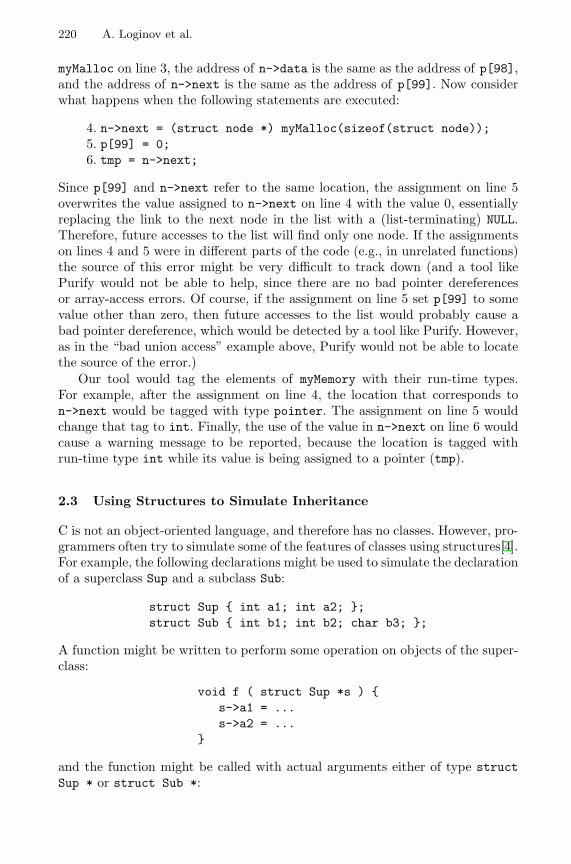
220 A. Loginov et al.
myMalloc on line 3, the address of n->data is the same as the address of p[98],and the address of n->next is the same as the address of p[99]. Now considerwhat happens when the following statements are executed:
4. n->next = (struct node *) myMalloc(sizeof(struct node));5. p[99] = 0;6. tmp = n->next;
Since p[99] and n->next refer to the same location, the assignment on line 5overwrites the value assigned to n->next on line 4 with the value 0, essentiallyreplacing the link to the next node in the list with a (list-terminating) NULL.Therefore, future accesses to the list will find only one node. If the assignmentson lines 4 and 5 were in different parts of the code (e.g., in unrelated functions)the source of this error might be very difficult to track down (and a tool likePurify would not be able to help, since there are no bad pointer dereferencesor array-access errors. Of course, if the assignment on line 5 set p[99] to somevalue other than zero, then future accesses to the list would probably cause abad pointer dereference, which would be detected by a tool like Purify. However,as in the “bad union access” example above, Purify would not be able to locatethe source of the error.)
Our tool would tag the elements of myMemory with their run-time types.For example, after the assignment on line 4, the location that corresponds ton->next would be tagged with type pointer. The assignment on line 5 wouldchange that tag to int. Finally, the use of the value in n->next on line 6 wouldcause a warning message to be reported, because the location is tagged withrun-time type int while its value is being assigned to a pointer (tmp).
2.3 Using Structures to Simulate Inheritance
C is not an object-oriented language, and therefore has no classes. However, pro-grammers often try to simulate some of the features of classes using structures[4].For example, the following declarations might be used to simulate the declarationof a superclass Sup and a subclass Sub:
struct Sup { int a1; int a2; };struct Sub { int b1; int b2; char b3; };
A function might be written to perform some operation on objects of the super-class:
void f ( struct Sup *s ) {s->a1 = ...s->a2 = ...
}
and the function might be called with actual arguments either of type structSup * or struct Sub *:
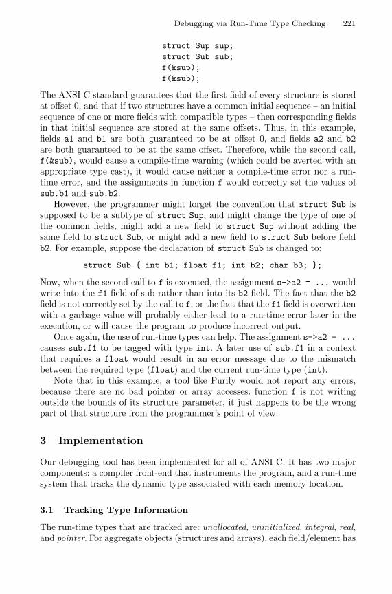
Debugging via Run-Time Type Checking 221
struct Sup sup;struct Sub sub;f(&sup);f(&sub);
The ANSI C standard guarantees that the first field of every structure is storedat offset 0, and that if two structures have a common initial sequence – an initialsequence of one or more fields with compatible types – then corresponding fieldsin that initial sequence are stored at the same offsets. Thus, in this example,fields a1 and b1 are both guaranteed to be at offset 0, and fields a2 and b2are both guaranteed to be at the same offset. Therefore, while the second call,f(&sub), would cause a compile-time warning (which could be averted with anappropriate type cast), it would cause neither a compile-time error nor a run-time error, and the assignments in function f would correctly set the values ofsub.b1 and sub.b2.
However, the programmer might forget the convention that struct Sub issupposed to be a subtype of struct Sup, and might change the type of one ofthe common fields, might add a new field to struct Sup without adding thesame field to struct Sub, or might add a new field to struct Sub before fieldb2. For example, suppose the declaration of struct Sub is changed to:
struct Sub { int b1; float f1; int b2; char b3; };
Now, when the second call to f is executed, the assignment s->a2 = ... wouldwrite into the f1 field of sub rather than into its b2 field. The fact that the b2field is not correctly set by the call to f, or the fact that the f1 field is overwrittenwith a garbage value will probably either lead to a run-time error later in theexecution, or will cause the program to produce incorrect output.
Once again, the use of run-time types can help. The assignment s->a2 = ...causes sub.f1 to be tagged with type int. A later use of sub.f1 in a contextthat requires a float would result in an error message due to the mismatchbetween the required type (float) and the current run-time type (int).
Note that in this example, a tool like Purify would not report any errors,because there are no bad pointer or array accesses: function f is not writingoutside the bounds of its structure parameter, it just happens to be the wrongpart of that structure from the programmer’s point of view.
3 Implementation
Our debugging tool has been implemented for all of ANSI C. It has two majorcomponents: a compiler front-end that instruments the program, and a run-timesystem that tracks the dynamic type associated with each memory location.
3.1 Tracking Type Information
The run-time types that are tracked are: unallocated, uninitialized, integral, real,and pointer. For aggregate objects (structures and arrays), each field/element has
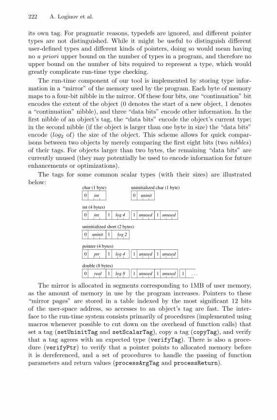
222 A. Loginov et al.
its own tag. For pragmatic reasons, typedefs are ignored, and different pointertypes are not distinguished. While it might be useful to distinguish differentuser-defined types and different kinds of pointers, doing so would mean havingno a priori upper bound on the number of types in a program, and therefore noupper bound on the number of bits required to represent a type, which wouldgreatly complicate run-time type checking.
The run-time component of our tool is implemented by storing type infor-mation in a “mirror” of the memory used by the program. Each byte of memorymaps to a four-bit nibble in the mirror. Of these four bits, one “continuation” bitencodes the extent of the object (0 denotes the start of a new object, 1 denotesa “continuation” nibble), and three “data bits” encode other information. In thefirst nibble of an object’s tag, the “data bits” encode the object’s current type;in the second nibble (if the object is larger than one byte in size) the “data bits”encode (log2 of) the size of the object. This scheme allows for quick compar-isons between two objects by merely comparing the first eight bits (two nibbles)of their tags. For objects larger than two bytes, the remaining “data bits” arecurrently unused (they may potentially be used to encode information for futureenhancements or optimizations).
The tags for some common scalar types (with their sizes) are illustratedbelow:
1 1unused unused10
0
0 1
10 1 1unused unused
0 1 1 1unused unused 1 . . .
0
int
int (4 bytes)
int
char (1 byte)
log 4
uninitialized short (2 bytes)
pointer (4 bytes)
double (8 bytes)
ptr log 4
uninit log 2
real log 8
uninitialized char (1 byte)
uninit
The mirror is allocated in segments corresponding to 1MB of user memory,as the amount of memory in use by the program increases. Pointers to these“mirror pages” are stored in a table indexed by the most significant 12 bitsof the user-space address, so accesses to an object’s tag are fast. The inter-face to the run-time system consists primarily of procedures (implemented usingmacros whenever possible to cut down on the overhead of function calls) thatset a tag (setUninitTag and setScalarTag), copy a tag (copyTag), and verifythat a tag agrees with an expected type (verifyTag). There is also a proce-dure (verifyPtr) to verify that a pointer points to allocated memory beforeit is dereferenced, and a set of procedures to handle the passing of functionparameters and return values (processArgTag and processReturn).
Debugging via Run-Time Type Checking 223
3.2 Source-Level Instrumentation
To instrument a program, the tool performs a source-to-source transformationon the C source files using Ckit[5], a C front end written in ML. Working at thesource level gives the tool access to all the source-level type information it needs.Also, the flexibility of the comma operator in C makes it possible to preservethe ANSI C semantics of the original program while retaining portability: aninstrumented C file can, in principle, be compiled on multiple platforms.1
Handling the C language was non-trivial because a number of C’s featuresmake correct instrumentation difficult. The following summary of the instru-mentation actions that the tool performs highlights some of the issues:
main: Every occurrence of main is renamed to prog main. Our run-timesystem defines its own main function, which performs some initialization be-fore calling prog main. This way, we can filter out command-line arguments forthe run-time system, and initialize the tags for the argv arrays. Also, this wayrecursive calls to main do not cause any problems.
statements and expressions: Each program statement and its componentexpressions are instrumented via a set of syntax-directed transformations. Codefor setting, copying, or verifying tags is added to expressions; the instrumentedcode makes extensive use of the comma operator (see Section 3.3 for an example).
locals: Local variables are initially tagged uninitialized. A local variable thatis initialized is processed as if the initialization expression were assigned to thatvariable. Because the instrumentation code needs to be able to take the addressof all variables, register variables are demoted to auto variables. Also, tags forbit fields are not initialized because C does not allow the address of a bit fieldto be taken; instead, bit fields remain tagged as uninitialized. This still triggerstype-violation warnings and errors if a bit field is used in a type-unsafe manner.
globals: Tags for global variables are initialized in a special init function;one such function is created per source file. Our main function calls each of theseinit functions before calling prog main. The list of init functions from thedifferent source files is collected at link time.
externs: extern variables that are not defined in any of the instrumentedsource files are treated specially. To allow instrumented source files to be linkedwith uninstrumented object code (most commonly library modules), we assumethat extern variables are “well-behaved”, and so initialize their tags to containtheir declared types. However, the tool is limited by what is visible to it. Inparticular, it cannot initialize the tags for incomplete array types (e.g., externint a[];) because the size of the array is not visible.
calls: To handle function calls, the tags of the function’s parameters must becommunicated between the caller and the callee. At the callsite, code is addedto store the tags for the actual parameters in an array, whose address is kept ina global pointer, globalArgTags. At the head of the function definition, code is1 Note: the Ckit front end does not currently support C-preprocessor directives, so at
present we can only instrument preprocessed C code. This limits portability to someextent, but is not a fundamental limitation of our approach.
224 A. Loginov et al.
added to extract the tags of the parameters passed to the function. The samemechanism is used to pass the tag of the return value back to the callsite. Toallow a mix of instrumented and uninstrumented functions to work properly,including where instrumented functions are invoked via callbacks from uninstru-mented functions, the instrumented caller stores the address of the callee in aglobal pointer, globalCallTarget, while the instrumented callee compares itsown address with globalCallTarget. If the addresses match, it means that thecaller is instrumented, so the tags for function arguments and return value areprocessed as described above. If the addresses do not match, however, it meansthat the caller is uninstrumented, so tags for function parameters cannot beextracted from globalArgTags.
return: At a return statement and at the end of a function f, the mirrorfor the entire stack frame of f must be cleared to unallocated. This is done byprocessReturn, a procedure in our run-time system. The start of the stack framefor f is assumed to be the greatest2 of the addresses of f ’s formal parameters (ifany) and the first local variable declared in f (a variable specially added by ourinstrumentation process). Since the call to processReturn itself has advancedthe stack-frame pointer beyond the end of f ’s stack frame, a lower bound onthe end of f ’s stack frame is obtained by taking the address of a local variabledeclared within processReturn itself.
3.3 Instrumentation Example
A C program is instrumented by transforming the statements contained in thebodies of the program’s functions. Expressions in each statement are replacedby the result of a call to the instrumentation function instr-expr, which takes asarguments (1) exp, the expression to be instrumented, (2) a boolean flag enforce,and (3) an optional pointer argument tagptr.
The enforce flag specifies whether the expression’s run-time type must matchits static type, i.e., if the expression is used in a context that is sensitive to itstype. For example, in the expression e1 + e2, the data in both e1 and e2 need toreflect their respective static types, so enforce must be true when instrumentingboth e1 and e2. On the other hand, for the expression &e, the type of the datain e is not relevant to the type-safety of &e, so e would be instrumented withenforce=false.
The presence of the optional pointer argument tagptr indicates, when instru-menting an expression e, that an enclosing expression needs access to e’s type.In such a case, tagptr is used to convey this information.
The output of applying instr-expr to three common expressions (e1 = e2, id,and ∗e), is shown in Table 1.3
2 Assuming that the stack grows downwards in memory (from high to low addresses).For stacks that grow upwards, we use the lowest of the addresses of f ’s formalparameters and its first local variable.
3 We omit some details that would only complicate the example. For instance, weactually perform slightly different actions for instrumenting lvalues and rvalues. Also,
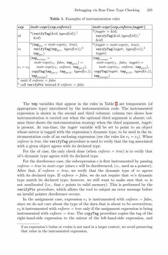
Debugging via Run-Time Type Checking 225
Table 1. Examples of instrumentation rules
exp instr-expr(exp,enforce) instr-expr(exp,enforce,tagptr)
id*(verifyTag(&id, typeof(id)),1
&id)
*(tagptr = &id,verifyTag(&id, typeof(id)),1
&id)
∗e*(tmpptr = instr-expr(e, true),verifyTag(tmpptr, typeof(∗e)),2tmpptr)
*(tagptr = instr-expr(e, true),verifyTag(tagptr, typeof(∗e)),2tagptr)
e1 = e2
(tmpassign =instr-expr(e1, false, tmpptr1) =instr-expr(e2, enforce, tmpptr2),
copyTag(tmpptr1, tmpptr2, typeof(e1)),tmpassign)
(tmpassign =instr-expr(e1, false, tagptr) =instr-expr(e2, enforce, tmpptr2),
copyTag(tagptr, tmpptr2, typeof(e1)),tmpassign)
1 omit if enforce = false2 call verifyPtr instead if enforce = false
The tmp variables that appear in the rules in Table 1 are temporaries (ofappropriate type) introduced by the instrumentation code. The instrumentedexpression is shown in the second and third columns: column two shows howinstrumentation is carried out when the optional third argument is absent; col-umn three shows the instrumentation strategy when the third argument, tagptr,is present. At run-time, the tagptr variable will be set to point to an objectwhose mirror is tagged with the expression’s dynamic type, to be used in the in-strumentation code of an enclosing expression (see the rules for e1 = e2). Whenenforce is true, the verifyTag procedure is used to verify that the tag associatedwith a given object agrees with its declared type.
For the id case, the only check done (when enforce = true) is to verify thatid ’s dynamic type agrees with its declared type.
For the dereference case, the subexpression e is first instrumented by passingenforce = true to instr-expr (since e will be dereferenced, i.e., used as a pointer).After that, if enforce = true, we verify that the dynamic type of ∗e agreeswith its declared type. If enforce = false, we do not require that ∗e’s dynamictype match its declared type; however, we still want to make sure that ∗e isnot unallocated (i.e., that e points to valid memory). This is performed by theverifyPtr procedure, which allows the tool to output an error message beforean invalid pointer dereference occurs.
In the assignment case, expression e1 is instrumented with enforce = false,since we do not care about the type of the data that is about to be overwritten;e2 is instrumented with enforce = true only if the assignment expression is beinginstrumented with enforce = true. The copyTag procedure copies the tag of theright-hand-side expression to the mirror of the left-hand-side expression, and
if an expression’s lvalue or rvalue is not used in a larger context, we avoid preservingthat value in the instrumented expression.
226 A. Loginov et al.
also issues a warning message if the type of the right-hand-side expression is notcompatible with the static type of the left-hand-side expression.
For the id and ∗e cases, the instrumented code has the form *(...,ptr); thisis so that the instrumented expression is a valid lvalue. An assignment expressionis not an lvalue, and so does not need to be instrumented in this way. However,if an assignment is used as an rvalue in a larger context, we must still makesure that the instrumented expression preserves the correct rvalue, which is thepurpose of tmpassign.
Now consider instrumenting the statement x = *p;. Since this assignmentdoes not occur in a context that uses its value, its type need not be verified,and the assignment is instrumented with enforce = false. Also, since there isno enclosing expression that needs access to the assignment’s type, the optionaltagptr argument is not needed. Assuming x is of type int and p is of type int *,the result of instr-expr(x = *p, false) is shown in Figure 1. Notice that the tmpvariable at the outermost level (for the assignment expression) has been omittedbecause in this case, the assignment’s rvalue does not need to be preserved.
*(tmp1 = &x, &x) =*(tmp2 = *(verifyTag(&p, pointer_type),
&p),verifyPtr(tmp2, sizeof(int)),tmp2),
copyTag(tmp1, tmp2, int_type)
Fig. 1. Output of instr-expr(x = *p, false)
3.4 Other Features
In order to perform proper type checking, the tool needs to handle memory-management functions specially. We replace each call to malloc (and its rela-tives) with our own version that, upon successfully allocating a block of memory,initializes the mirror for that memory block with the uninitialized tag. Similarly,our free function resets the mirror to be of unallocated type. Our versions ofthese functions do their own bookkeeping so we know how many bytes are beingfreed by a call on free at run-time. Our version of malloc also adds paddingbetween allocated blocks to decrease the likelihood of a stray pointer jumpingfrom one block to another (this is the approach used by Purify). For the stackallocation function alloca, we instrument the callsites to additionally invokeprocedures to initialize the newly allocated stack space.
Another routine that is handled specially is the variable argument routineva arg (usually implemented as a macro). Our portable solution assumes thatthe argument obtained is properly typed, so we instrument each invocation ofva arg to return a tag of the expression’s static type.
Debugging via Run-Time Type Checking 227
As mentioned in Section 3.2, the approach we have taken allows us to linkinstrumented modules with uninstrumented ones, with the only requirementbeing that the program’s main function must be renamed to prog main. Thisflexibility is useful if, for example, a programmer only wants to debug one smallcomponent of a large program: they can instrument just the files of interest, andlink them in with the other uninstrumented object modules. A caveat when doingthis, however, is that it may lead to the reporting of spurious warning and errormessages because the uninstrumented parts of the code do not maintain typeinformation. For example, if a reference to a valid object in the uninstrumentedportion of the program is passed to an instrumented function, the tool will thinkthat the object is unallocated, and may output spurious errors and warnings.
This problem extends, in general, to library modules. For example, the flowof values in a function like memcpy, the initialization of values from input in afunction like fgets, and the types of the data in a static buffer returned by afunction like ctime would not be captured. To handle these, we have created acollection of instrumented versions of common library functions that affect typeflow. These are wrappers of the original functions, hand-written to perform thenecessary tag-update operations to capture their type behavior.
Finally, our tool lends itself naturally to interactive debugging. When a warn-ing or error message is issued, a signal (SIGUSR1) is sent, and can be interceptedby an interactive debugger like GDB[6]. The user is then able to examine mem-ory locations, including the mirror, and make use of GDB’s features to bettertrack down the cause of an error.
4 Experiments
To test the effectiveness of our debugging tool, we used Fuzz[7] to find Solarisutilities that crash on some inputs, and instrumented five such programs fortesting (nroff, plot, ul, units, col). We also tracked down bugs that appear intwo programs from the Olden benchmark suite (health, voronoi). A summaryof what our tool revealed about these runs is given below.
nroff: An array of pointers is accessed with a negative index, and the re-trieved word, when dereferenced, causes a segmentation fault. The instrumentedprogram, before crashing, warns that the retrieved word that is about to bedereferenced actually contains an array of characters.
plot: A rogue pointer, after passing beyond the bounds of a local array,walks up the stack, writing bytes as it goes. It eventually attempts to write toinvalid memory, at which point the program crashes. The instrumented programoutputs a long list of warning messages signaling these writes to unallocatedmemory, accurately identifying the line of code where this occurs.
ul: The original program crashes during a call to fgetwc, while the instru-mented program crashes during a call to fprintf as our instrumentation codeis attempting to write a warning message. The cause of the crash in the origi-nal program was difficult to diagnose, but “accessing unallocated memory” errormessages generated by our instrumented program led us to the cause of the crash:
228 A. Loginov et al.
a pointer, after passing beyond the bounds of an array, walks through the bsssection and eventually overwrites part of the global iob array (which containsinformation about stdin, stdout, and stderr). This causes the subsequent callto fgetwc in the original code, and fprintf in the instrumented code, to crash.
units: In the original program, an errant pointer manages to corrupt the“save” area of the call stack, resulting in bizarre behavior that was difficult totrack down without our tool. The instrumented program issues a type-violationerror message after the character pointer cp is set to point to itself, and issubsequently used to write a character value onto itself. The next dereference ofcp generates another error message, and then the program crashes.
col: The original program crashes on a dereference of a bad pointer, but ourinstrumented program does not crash; instead, it fails to terminate (at least,after two hours we stopped waiting for it to terminate). The first of many errormessages generated by our instrumented program signals a dereference into un-allocated memory, and points to the line in the program where the crash occurs(in the uninstrumented code). The point where the error message was generatedis close to where the pointer first stepped out of bounds of the global array towhich it pointed.
health: In the semantics of C, memory allocated by malloc, unlike calloc,is not required to be zero-initialized, although many programmers assume thatit is. In this program, the pointer fields in two recursive data structures arenot initialized after allocation via malloc. While traversing these structures, theoriginal program counts on the pointer fields being NULL to indicate the absenceof a substructure. The instrumented program warns of an access to uninitializedmemory each time the program checks to see if one of these pointer fields is NULL.On our testing platform, all the memory allocated with malloc in this programhappen to be zero-initialized and so the program does not crash. However, theerroneous assumption about malloc is a program flaw that may cause a crashon a different execution (or when the program is run on a different platform).
voronoi: Some bit-level manipulations are performed on a pointer to a struct,yielding a pointer to a “field” that does not belong to the struct, since someassumptions made by voronoi about the size of the struct do not hold on ourtest machine. A subsequent assignment of this pointer (as a function argument)generates a warning message stating that an unallocated object is being passed.Later, when the pointer (which happens to be NULL) is actually dereferenced, theinstrumented program gives an “accessing unallocated memory” error messagebefore crashing.
In most cases, crashes in the test programs were found to have been caused bya pointer (or array index) that had gone astray. In every case, our tool was ableto detect the out-of-bounds memory accesses because the type of the pointed-to memory was different from the expected type. While these results are veryencouraging, these kinds of errors would also be detected by Purify.
We can easily create examples (such as the ones given in Section 2) for whichour tool is able to detect errors that are not detected by Purify; however, we havenot yet found examples of those kinds of bugs in real programs. We suspect that
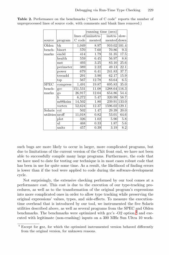
Debugging via Run-Time Type Checking 229
Table 2. Performance on the benchmarks (“Lines of C code” reports the number ofunpreprocessed lines of source code, with comments and blank lines removed.)
running time (secs)lines of uninstru- instru- slow-
source program C code mented mented downOlden bh 1,049 8.97 910.02 101.4bench- bisort 570 7.60 70.86 9.3marks em3d 414 1.79 31.35 17.5
health 559 6.45 56.97 8.8mst 493 3.25 83.10 25.6perimeter 389 2.22 49.13 22.1power 679 6.41 241.83 37.7treeadd 291 3.90 62.17 15.9tsp 567 12.78 83.64 6.5
SPEC compress 1,491 19.87 695.83 35.0bench- gcc 151,531 11.08 1288.64 116.3marks go 26,917 12.04 654.86 54.4
li 6,272 5.47 320.99 58.7m88ksim 14,502 1.80 239.91 133.0vortex 52,624 12.37 1596.02 129.1
Solaris col 502 1.47 29.39 20.0utilities nroff 11,018 0.82 53.01 64.6
plot 326 1.02 5.90 5.8ul 468 0.33 1.87 5.6units 457 0.39 3.19 8.2
such bugs are more likely to occur in larger, more complicated programs, butdue to limitations of the current version of the Ckit front end, we have not beenable to successfully compile many large programs. Furthermore, the code thatwe have used to date for testing our technique is in most cases robust code thathas been in use for quite some time. As a result, the likelihood of finding errorsis lower than if the tool were applied to code during the software-developmentcycle.
Not surprisingly, the extensive checking performed by our tool comes at aperformance cost. This cost is due to the execution of our type-tracking pro-cedures, as well as to the transformation of the original program’s expressionsinto more complicated ones in order to allow type tracking while preserving theoriginal expressions’ values, types, and side-effects. To measure the execution-time overhead that is introduced by our tool, we instrumented the five Solarisutilities described above, as well as several programs from the SPEC and Oldenbenchmarks. The benchmarks were optimized with gcc’s -O2 option,4 and exe-cuted with legitimate (non-crashing) inputs on a 300 MHz Sun Ultra 10 work-
4 Except for gcc, for which the optimized instrumented version behaved differentlyfrom the original version, for unknown reasons.
230 A. Loginov et al.
station with 256 MB of RAM and 1.1 GB of virtual memory. The sizes of thebenchmarks, as well as the execution times (user+system time, in seconds) andslowdowns are reported in Table 2.
The slowdowns we observe on these benchmarks range from about 6 timesto 130 times, with a median of 23.8. As a point of comparison, the slowdownfactor for Purify tends to be in the range of 10 to 20. The exorbitant slowdownfor bh is due mainly to the program making many assignments of structures,for which our tag-copying procedure copyTag performs an inefficient nibble-by-nibble copy. For the SPEC benchmarks, as well as for nroff, the performancedegradation is largely due to the overhead of writing out spurious warning anderror messages. These mainly result from the tool’s inability to cleanly capturethe type behavior of calloc-initialized memory and incomplete array types (inparticular, the ctype array, which is used by ctype.h macros), and also fromsome of these programs performing masking operations which treat integers asarrays of characters – technically a type violation.
Future work includes using the results of static analysis to reduce the amountof instrumentation introduced by our tool (thus reducing its overhead). For ex-ample, if the value in a location is used multiple times, and there is no possibilitythat its type is modified between the uses, then only the first use needs to bechecked.
5 Related Work
Run-time type-checking is not a new idea. It has been implemented in functional-style languages like LISP and Scheme, and object-oriented languages like Java,Smalltalk and Objective-C. However, designing dynamic type-checking for a lan-guage like C that includes unions, structures, arrays without bounds checking,casting and pointer arithmetic is a large undertaking. Additionally, there is asubtle difference in approach. Traditional dynamic type-checking attaches tagsto data, while our approach separates the tag space from the data space. Bothapproaches attain good spatial locality of accesses (in the case of separated tagsand data, the locality of tag accesses mirrors the locality of data accesses). How-ever, if checking of some of the tags can be eliminated based on static analysis,the locality of accesses to data does not suffer as it does in the case of co-locatedtags and data.
Another significant advantage is the fact that the tags can be protectedfrom erroneous accesses by the user code. User code is simply less likely tomake erroneous accesses to the separated tag space, and if better guaranteesare required, memory-protecting hardware can be used to shield the tag spaceduring the execution of user code.
The concept of soft typing [8,9] was introduced in an effort to combine thebenefits of static and dynamic typing for functional-style languages. In this ap-proach, static typing is employed to identify program statements that do notstatically type check. These statements are subsequently instrumented to bedynamically type-checked. The earlier work [8] concentrates on presenting aframework for soft typing on a restricted class of programming languages; the
Debugging via Run-Time Type Checking 231
latter work [9] extends this work to handle realistic languages like Scheme. Byaddressing a traditionally dynamically typed language, the emphasis was puton the application of soft typing as a way of lowering the run-time overheadof type-checking. While this body of work is similar to ours in its approach totype-checking, the differences in the languages handled by the two approachesis significant.
Approaches to detection of errors in C programs by means of executing a pro-gram instrumented to perform run-time checks have been developed in the past.Safe-C[2] provides run-time detection of array access and pointer dereferenceerrors, such as array out-of-bounds errors, stale-pointer accesses, and accessesresulting from erroneous pointer arithmetic. This is done by keeping track ofattributes of the referent of each pointer by transforming C code to C++ code,and taking advantage of operator overloading to perform appropriate checkswhenever certain operators are applied. Purify[1] detects errors similar to thosefound by Safe-C, and, in addition, identifies uninitialized memory reads andmemory leaks. Purify performs these checks by instrumenting object files andmodifying the layout of heap-allocated memory in order to catch access errors.Our approach catches all of these errors in addition to run-time type violationsthat are not covered by Purify and Safe-C. Furthermore, the warning messagesprovided by our tool provide a history of suspicious type propagation that canaid in pinpointing the true cause of an error.
In the realm of security, tools have been developed to prevent “stack smash-ing” (where the return address in the activation record is modified by a maliciousagent to obtain control of the program)[10,11]. Our tool also detects such at-tacks, which fall under the general category of “type errors” detected by ourtool.
A technique to enable efficient checking of array-access and pointer-dereference errors in a multiprocessor environment was presented in [3]. Theyachieve low-cost checking by creating a version of the program that contains onlycomputations that affect pointer and array accesses, instrumenting that version,and running it in parallel with the original program. We may be able to use thistechnique to improve our tool’s performance.
There have also been a number of efforts to address the problem of identifyingerrors in C programs due to out-of-bounds array indexes and misuses of typecasts based on the use of static analysis. Work on static analysis that can beapplied to checking for out-of-bounds array accesses includes [12,13,14,15,16].Algorithms for points-to analysis that distinguish among fields of structures [17,18] and for so-called “physical type checking” [19] can also be used to performstatic safety checks. However, most of the work based on static analysis citedabove has used flow-insensitive techniques, which is likely to cause an enormousnumber of warnings of possible misuses to be generated when applied to safetychecking of real-life C programs. The advantage of a dynamic type-checkingtool like the one reported in this paper is the ability to obtain more accurateinformation about type misuses and access errors, albeit only for ones that occurduring a given run of the program.
232 A. Loginov et al.
References
1. R. Hasting and B. Joyce. Purify: Fast detection of memory leaks and access errors.In Proceedings of the Winter Usenix Conference, 1992.
2. T. Austin, S. Breach, and G. Sohi. Efficient detection of all pointer and array accesserrors. In ACM SIGPLAN ’94 Conference on Programming Language Design andImplementation, 1994.
3. H. Patil and C. Fischer. Low-cost, concurrent checking of pointer and array accessesin C programs. Software–Practice and Experience, 27(27):87–110, 1997.
4. M. Siff, S. Chandra, T. Ball, K. Kunchithapadam, and T. Reps. Coping withtype casts in C. In Proc. of ESEC/FSE ’99: Seventh European Softw. Eng. Conf.and Seventh ACM SIGSOFT Symp. on the Found. of Softw. Eng., pages 180–198,September 1999.
5. Ckit. http://cm.bell-labs.com/cm/cs/what/ smlnj/doc/ckit/.6. R. Stallman and R. Pesch. Using GDB: A Guide to the GNU Source-Level Debug-
ger. July 1991.7. B. Miller, D. Koski, C.P. Lee, V. Maganty, R. Murthy, A. Natarajan, and J. Steidl.
Fuzz revisited: A re-examination of the reliability of UNIX utilities and services.Technical report, University of Wisconsin-Madison, 1995.
8. M. Fagan. Soft typing: An approach to type checking for dynamically typed lan-guages. Technical Report TR92-184, Department of Comp. Sci., Rice Univ., Hous-ton, TX, USA, March 1998.
9. A. Wright. Practical soft typing. Technical Report TR94-236, Department ofComp. Sci., Rice Univ., Houston, TX, USA, April 1998.
10. Immunix stack guard. http://immunix.org/stackguard.html.11. Stack shield. http://www.angelfire.com/sk/stackshield/info.html.12. P. Cousot and N. Halbwachs. Automatic discovery of linear restraints among
variables of a program. In Conf. Rec. of the Fifth annual ACM Symp. on Princ.of Prog. Lang., pages 84–96. ACM, January 1978.
13. C. Verbrugge, P. Co, and L.J. Hendren. Generalized constant propagation: A studyin C. In 6th Int. Conf. on Compiler Construction, volume 1060 of Lec. Notes inComp. Sci., pages 74–90. Springer, April 1996.
14. R. Rugina and M. Rinard. Symbolic bounds analysis of pointers, array indices, andaccessed memory regions. In SIGPLAN Conf. on Prog. Lang. Design and Impl.,pages 182–195, New York, NY, 2000. ACM Press.
15. R. Bodik, R. Gupta, and V. Sarkar. ABCD: Eliminating array bounds checks ondemand. In SIGPLAN Conf. on Prog. Lang. Design and Impl., pages 321–333,New York, NY, 2000. ACM Press.
16. D. Wagner, J.S. Foster, E.A. Brewer, and A. Aiken. A first step towards auto-mated detection of buffer overrun vulnerabilities. In Symposium on Network andDistributed Systems Security (NDSS ’00), pages 3–17, San Diego, CA, February2000.
17. B. Steensgaard. Points-to analysis by type inference of programs with structuresand unions. In 6th Int. Conf. on Compiler Construction, volume 1060 of Lec. Notesin Comp. Sci., pages 136–150. Springer, April 1996.
18. S. Yong, S. Horwitz, and T. Reps. Pointer analysis for programs with structuresand casting. In ACM SIGPLAN ’99 Conference on Programming Language Designand Implementation, pages 91–103, May 1999.
19. S. Chandra and T. Reps. Physical type checking for C. In Proc. of PASTE ’99:SIGPLAN-SIGSOFT Workshop on Program Analysis for Softw. Tools and Eng.,pages 66–75, New York, NY, 1999. ACM.
Library-Based Design and Consistency Checkingof System-Level Industrial Test Cases
Oliver Niese1, Bernhard Steffen2, Tiziana Margaria1, Andreas Hagerer1,Georg Brune3, and Hans-Dieter Ide3
1 METAFrame Technologies GmbH, Dortmund, Germany{ONiese, TMargaria, AHagerer}@METAFrame.de
2 Chair of Programming Systems, University of Dortmund, [email protected]
3 Siemens AG, Witten{Georg.Brune, Hans-Dieter.Ide}@wit.siemens.de
Abstract. In this paper we present a new coarse grain approach to auto-mated integrated (functional) testing, which combines three paradigms:library-based test design, meaning construction of test graphs by combi-nation of test case components on a coarse granular level, incrementalformalization, through successive enrichment of a special-purpose envi-ronment for application-specific test development and execution, andlibrary-based consistency checking, allowing continuous verification ofapplication- and aspect-specific properties by means of model checking.These features and their impact for the test process and the test engineersare illustrated along an industrial application: an automated integratedtesting environment for CTI-Systems.
1 Introduction
The increasing complexity of today’s testing scenarios for telephony systemsdemands for an integrated, open and flexible approach to support the manage-ment of the overall test process, i.e. specification of tests, execution of tests andanalysis of test results. Furthermore, systems under test (SUT) become com-posite (e.g. including Computer Telephony Integrated (CTI) platform aspects),embedded (due to hardware/software codesign practices), reactive, and run ondistributed architectures (e.g. client/server architectures). As a consequence, itbecomes increasingly unrealistic to restrict the consideration of the testing ac-tivities to single units of the systems, since complex subsystems affect each otherand require scalable, integrated test methodologies.
The requirements discussed in this paper exceed the capabilities of today’stesting tools. To our knowledge there exist neither commercial nor academictools providing comprehensive support for the whole system-level test process.In particular, most research on test automation for telecommunication systemsconcentrates on the generation of test cases and test suites on the basis of aformal model of the system: academic tools, like TORX [22], TGV [2], Autolink[13], and commercial ones like Telelogic Tau [21] presuppose the existence of
H. Hussmann (Ed.): FASE 2001, LNCS 2029, pp. 233–248, 2001.c© Springer-Verlag Berlin Heidelberg 2001
234 O. Niese et al.
fine-granular system models in terms of either automata or SDL descriptions,and aim at supporting the generation of corresponding test cases and test suites.This approach failed to enter practice in the scenario we are considering here,because it did not fit the current test design practice, in particular because theredoes not exist any fine granular formal model of the involved systems.
Therefore in our approach we aim at a formal methods-controlled,component-based test design on top of a library of elementary but intuitively un-derstandable test case fragments. This establishes a coarse-granular ‘meta-level’on which
– test engineers are used to think,– test cases and test suites can be easily composed,– test scenarios can be configured and initialized,– critical consistency requirements including version compatibility and frame
conditions for executability are easily formulated (see Section 5), and– consistency is fully automatically enforced via model checking and error di-
agnosis.
Already after a few months of cooperation this coarse-granular test manage-ment support was successfully put into practice, drastically strengthening thepre-existing test environment. We are not aware of any other test environmentsystematically addressing the needs of coordinating the highly heterogeneoustest process, let alone on the basis of formal methods.
The paper is organized as follows: Sect. 2 describes our application domain,system level testing of telephony systems, presents a concrete scenario, and in-troduces the requirements to the corresponding integrated testing environment.Sect. 3 presents our test coordinator tool, Sect. 4 describes the formal founda-tions of its design and analysis core, Sect. 5 shows the aspect-oriented characterof the automated verification by discussing concrete classes of constraints, andSect. 6 discusses the impact of the new environment on the test developmentpractice. Finally Sect. 7 draws our conclusions.
2 System-Level Testing of Telephony Systems
As a typical example of an integrated CTI platform, Fig. 1 shows a midrangetelephone switch and its environment. The switch is connected to the ISDNtelephone network or, more generally, to the public service telephone network(PSTN), and acts as a “normal” telephone switch to the phones. Additionally,it communicates directly via a LAN or indirectly via an application server withCTI applications that are executed on PCs. Like the phones, CTI applicationsare active components: they may stimulate the switch (e.g. initiate calls), andthey react to stimuli sent by the switch (e.g. notify incoming calls). In a systemlevel test it is therefore necessary to investigate the interaction between suchsubsystems.
Typically, each participating subsystem requires an individual test tool (seeSect. 3). Thus in order to test systems composed of several independent sub-systems that communicate with each other, one must be able to coordinate a
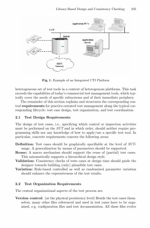
Library-Based Design and Consistency Checking 235
Fig. 1. Example of an Integrated CTI Platform
heterogeneous set of test tools in a context of heterogenous platforms. This taskexceeds the capabilities of today’s commercial test management tools, which typ-ically cover the needs of specific subsystems and of their immediate periphery.
The remainder of this section explains and structures the corresponding cen-tral requirements for practice-oriented test management along the typical cor-responding lifecycle: test case design, test organization, and test coordination.
2.1 Test Design Requirements
The design of test cases, i.e., specifying which control or inspection activitiesmust be performed on the SUT and in which order, should neither require pro-gramming skills nor any knowledge of how to apply/use a specific test tool. Inparticular, concrete requirements concern the following areas:
Definition: Test cases should be graphically specifiable at the level of SUT-usage. A generalization by means of parameters should be supported.
Reuse: A macro mechanism should support the reuse of (partial) test cases.This automatically supports a hierarchical design style.
Validation: Consistency checks of tests cases at design time should guide thedesigner towards building (only) plausibile test cases.
Variation: Rule-based controlled as well as randomized parameter variationshould enhance the expressiveness of the test results.
2.2 Test Organization Requirements
The central organizational aspects of the test process are:
Version control: (at the physical persistency level) Beside the test cases them-selves, many other files referenced and used in test cases have to be orga-nized, e.g. configuration files and test documentation. All these files evolve
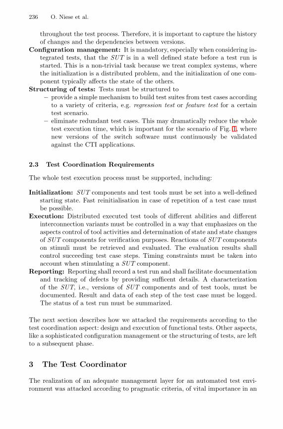
236 O. Niese et al.
throughout the test process. Therefore, it is important to capture the historyof changes and the dependencies between versions.
Configuration management: It is mandatory, especially when considering in-tegrated tests, that the SUT is in a well defined state before a test run isstarted. This is a non-trivial task because we treat complex systems, wherethe initialization is a distributed problem, and the initialization of one com-ponent typically affects the state of the others.
Structuring of tests: Tests must be structured to– provide a simple mechanism to build test suites from test cases according
to a variety of criteria, e.g. regression test or feature test for a certaintest scenario.
– eliminate redundant test cases. This may dramatically reduce the wholetest execution time, which is important for the scenario of Fig. 1, wherenew versions of the switch software must continuously be validatedagainst the CTI applications.
2.3 Test Coordination Requirements
The whole test execution process must be supported, including:
Initialization: SUT components and test tools must be set into a well-definedstarting state. Fast reinitialisation in case of repetition of a test case mustbe possible.
Execution: Distributed executed test tools of different abilities and differentinterconnection variants must be controlled in a way that emphasizes on theaspects control of tool activities and determination of state and state changesof SUT components for verification purposes. Reactions of SUT componentson stimuli must be retrieved and evaluated. The evaluation results shallcontrol succeeding test case steps. Timing constraints must be taken intoaccount when stimulating a SUT component.
Reporting: Reporting shall record a test run and shall facilitate documentationand tracking of defects by providing sufficent details. A characterizationof the SUT, i.e., versions of SUT components and of test tools, must bedocumented. Result and data of each step of the test case must be logged.The status of a test run must be summarized.
The next section describes how we attacked the requirements according to thetest coordination aspect: design and execution of functional tests. Other aspects,like a sophisticated configuration management or the structuring of tests, are leftto a subsequent phase.
3 The Test Coordinator
The realization of an adequate management layer for an automated test envi-ronment was attacked according to pragmatic criteria, of vital importance in an
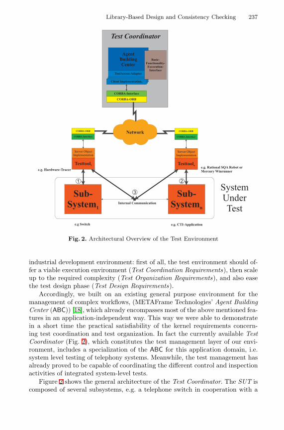
Library-Based Design and Consistency Checking 237
Fig. 2. Architectural Overview of the Test Environment
industrial development environment: first of all, the test environment should of-fer a viable execution environment (Test Coordination Requirements), then scaleup to the required complexity (Test Organization Requirements), and also easethe test design phase (Test Design Requirements).
Accordingly, we built on an existing general purpose environment for themanagement of complex workflows, (METAFrame Technologies’ Agent BuildingCenter (ABC)) [18], which already encompasses most of the above mentioned fea-tures in an application-independent way. This way we were able to demonstratein a short time the practical satisfiability of the kernel requirements concern-ing test coordination and test organization. In fact the currently available TestCoordinator (Fig. 2), which constitutes the test management layer of our envi-ronment, includes a specialization of the ABC for this application domain, i.e.system level testing of telephony systems. Meanwhile, the test management hasalready proved to be capable of coordinating the different control and inspectionactivities of integrated system-level tests.
Figure 2 shows the general architecture of the Test Coordinator. The SUT iscomposed of several subsystems, e.g. a telephone switch in cooperation with a
238 O. Niese et al.
CTI application. Each subsystem is controlled via its own test tools1. The testtools have access to external interfaces ( 1©, 2©) as well as to some internal ones( 3©). They are steered by the Test Coordinator. For more details concerning theintegration process of the test tools see [8].
Up to now, the effort in the project was mainly devoted to the supportof test design and to the handling of advanced coordination and organizationrequirements.
3.1 ABC’s Enabling Characteristics
The following characteristics of the ABC proved to be of major importance,due to the heterogeneous composition of the team (researchers, developers, andprospective industrial users coming from different groups within Siemens, withdifferent focus on the project).
Behaviour-Oriented Development: In general, application development in theABC, which goes far beyond the domain of CTI applications [18,17], consistsof behaviour-oriented combination of building blocks on a coarse granular level.Building blocks are identified on a functional basis, understandable to appli-cation experts, and usually encompass a number of ‘classical’ programmingunits (be they procedures, classes, modules, or functions). They are organizedin application-specific collections (palettes). In contrast to (other) component-based approaches, e.g., for object-oriented program development, ABC focusseson the dynamic behaviour: (complex) functionalities are graphically stuck to-gether to yield flow graph-like structures embodying the application behaviourin terms of control. This graph structure is independent of the paradigm of theunderlying programming language. In particular, we view this flow-graph struc-ture as a control-oriented coordination layer on top of data-oriented communi-cation mechanisms enforced, e.g., via RMI, CORBA or (D)COM. Concretely,the test management layer communicates with individual test tools by means ofCORBA [10]. Accordingly, the purely graphical combination of building blocks’behaviours happens at a more abstract level.
Incremental Formalization: The successive enrichment of the application-specificdevelopment environment is two-dimensional. Beside the library of application-specific building blocks, which dynamically grows whenever new functionalitiesare made available, ABC supports the dynamic growth of a hierarchically orga-nized library of constraints, controlling and governing the adequate use of thesebuilding blocks within application programs. This library is intended to growwith the experience gained while using the environment, e.g., detected errors,strengthened policies, and new building blocks may directly impose the additionof constraints. It is the possible looseness of these constraints which makes the1 Test tools can be e.g. proprietary hardware tracer for testing the switch or GUI
test tools such as Rational SQA Robot [12] or Mercury Winrunner [7] for the test ofapplications.
Library-Based Design and Consistency Checking 239
constraints highly reusable and intuitively understandable. Here we consciouslyprivilege understandability and practicality of the specification mechanisms overtheir completeness.
Library-Based Consistency Checking: Throughout the behaviour-oriented devel-opment process, ABC offers access to mechanisms for the verification of librariesof constraints via model checking. The model checker individually checks hun-dreds of typically very small and application- and purpose-specific constraintsover the flow graph structure. This allows concise and comprehensible diagnosticinformation in the case of a constraint violation, in particular as the informationis given at the application rather than at the programming level.
Taken together, these characteristics of the basic tool were actually the realenablers for the project results, in particular, as they provided a means to seam-lessly coordinate the cooperation between ABC team, CTI expert, test designers,and test engineers.
4 Domain Modelling
This section summarizes the effort for instantiating the ABC as required for theCTI application. This mainly consists of the design of some application-specificbuilding blocks, and the formulation of the frame conditions which must beenforced during test case design and test suite design.
4.1 Test Building Blocks
The ABC team, the CTI experts and the test designers define and also classifythe building blocks occurring in the testing experiments, typically accordingto technical criteria like version or specific hardware or software requirements,origin (where they were developed) and, here, most importantly, according totheir intent for the specific application area.
The resulting classification scheme is a simplified version of the taxonomiesused in [6] and [17]. At this stage, the building blocks occurring in the test casesare organized in palettes, accessible from the Test Coordinator’s GUI (see Fig.3,left), which are the basis for the test designers to graphically construct test casesby drag-and-drop. The test case design is completed by
– connecting the test blocks by edges, and– configuring the internal parameters.
The resulting test graphs are directly executable for test purposes, and, at thesame time, they constitute the models for our verification machinery by meansof model checking. Figure 3 shows a typical test graph for illustration.
The palettes are thus central to build the models, and they constitute avocabulary for the constraint definition in terms of modal formulas. Typically, thedesign of the classification scheme and of the constraints goes hand in hand withthe definition of aspect-specific views and filters: both are mutually supportivemeans to an application specific structuring of the design process.
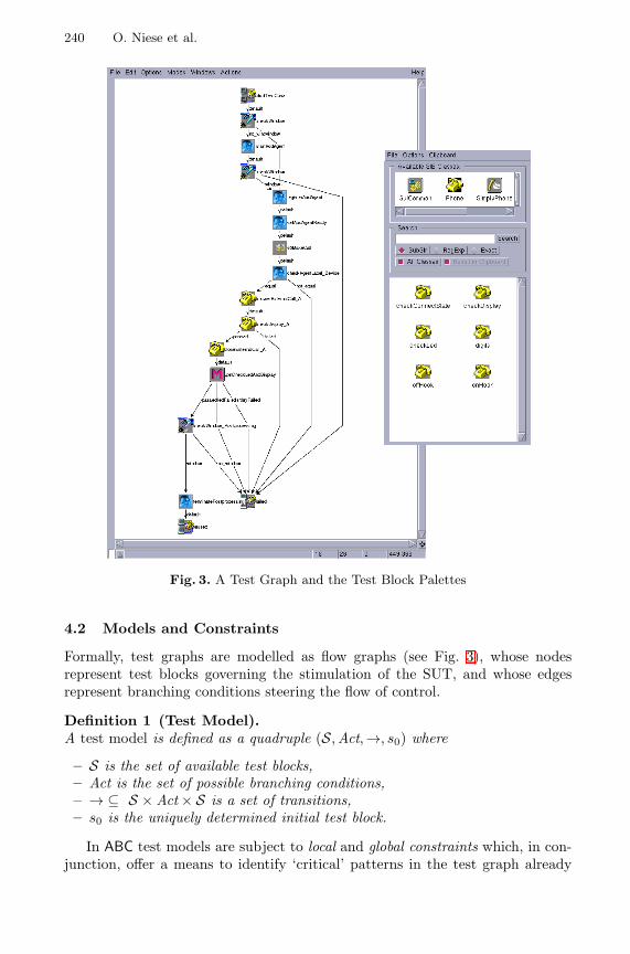
240 O. Niese et al.
Fig. 3. A Test Graph and the Test Block Palettes
4.2 Models and Constraints
Formally, test graphs are modelled as flow graphs (see Fig. 3), whose nodesrepresent test blocks governing the stimulation of the SUT, and whose edgesrepresent branching conditions steering the flow of control.
Definition 1 (Test Model).A test model is defined as a quadruple (S,Act,→, s0) where
– S is the set of available test blocks,– Act is the set of possible branching conditions,– → ⊆ S × Act × S is a set of transitions,– s0 is the uniquely determined initial test block.
In ABC test models are subject to local and global constraints which, in con-junction, offer a means to identify ‘critical’ patterns in the test graph already
Library-Based Design and Consistency Checking 241
during the early design phase. The classification of constraints into local andglobal is important, since each kind requires a specific treatment. The on-lineverification during the design of a new test, however, captures both kinds ofconstraints.
Local Constraints. Local constraints specify single test blocks in the context oftheir immediate neighbours: they capture a test block’s branching potential aswell as its admissible subsequent parameterization. Their correctness is checkedby means of specific algorithms, which can be activated at need. The verificationof local constraints is invoked automatically during the verification process ofglobal properties.
Global Constraints: The Temporal Aspect. Global constraints allow users to spec-ify causality, eventuality and other relationships between test blocks, which maybe necessary in order to guarantee frame conditions for e.g., executability andversion compatibility.
A test property is global if it does not only involve the immediate neighbour-hood of a test block in the test model2, but also relations between test blockswhich may be arbitrarily distant and separated by arbitrarily heterogeneoussubmodels (see Section 5 for concrete examples).
The treatment of global properties is required in order to capture the essenceof the expertise of designers about do’s and don’ts of test creation, e.g. whichtest blocks are incompatible, or which can or cannot occur before/after someother test blocks. Such properties are rarely straightforward, sometimes theyare documented as exceptions in thick user manuals, but more often they arenot documented at all, and have been discovered at a hard price as bugs ofpreviously developed tests. They are perfect examples of the kind of preciousdomain-specific knowledge that expert designers accumulate over the years, andwhich is therefore particularly worthwhile to include in the test design environ-ment for successive automatic reuse.
In the presented environment such properties are gathered as SLTL formu-las (see below) in Constraint Libraries (see Fig. 4, right), which can be easilyupdated and which are automatically accessed by our model checker during theverification.
Definition 2 (SLTL).
The syntax of Semantic Linear-time Temporal Logic (SLTL) is given in BNFformat by:
Φ ::= A | ¬Φ | (Φ ∧ Φ) | < c > Φ | G(Φ) | (ΦUΦ)
where A represents the set of atomic propositions overS, and c a possible branch-ing condition expressed as a propositional logic formula over Act.2 The neighbourhood consists of the set of all the predecessors/successors of a test
block along all paths in the model.
242 O. Niese et al.
The SLTL formulas are interpreted over the set of all legal test sequences, i.e.alternating sequences of test blocks and conditions which start and end with testblocks. The semantics of SLTL formulas is now intuitively defined as follows:3
– A is satisfied by every test sequence whose first element (a test block)satisfies the atomic proposition A. Atomic propositions capture local testblock specifications formulated as simple propositional logic formulas.
– Negation ¬ and conjunction ∧ are interpreted in the usual fashion.
– Next-time operator < > :< c > Φ is satisfied by all test sequences whose second element (the firstcondition) satisfies c and whose continuation4 satisfies Φ. In particular,< tt > Φ is satisfied by every test sequence whose continuation satisfies Φ.
– Generally operator G:G(Φ) requires that Φ is satisfied for every suffix.
– Until operator U:(ΦUΨ) expresses that the property Φ holds at all test blocks of the sequence,until a position is reached where the corresponding continuation satisfies theproperty Ψ . Note that ΦUΨ guarantees that the property Ψ holds eventually(strong until).
The definitions of continuation and suffix may seem complicated at first. How-ever, thinking in terms of paths within a flow graph clarifies the situation: asubpath always starts with a node (a test block) again (see also Fig. 3).
The interpretation of the logic over test models is defined path-wise: a testmodel satisfies a SLTL formula if all its paths do.
The introduction of derived operators supports a modular and intuitiveformulation of complex properties. Convenient are the dual operators:
Disjunction: Φ ∨ Ψ =df ¬ (¬Φ ∧ ¬Ψ)Eventually: F(Φ) =df ¬G(¬Φ) = (tt U Φ)
5 Typical Constraints
This section summarizes some typical constraints in order to illustrate the styleand common patterns in temporal constraint specification for test cases. Techni-cally, the following examples comprise modalities and examples for constraintswritten in our first-order extension of SLTL [3]. From the application point ofview, we distinguish classes of constraints concerning different aspects of the ap-plication domain, which in particular differ in their scoping, i.e. not necessarilyevery test case must fulfill all constraints because it depends on the test purpose,which constraints are bound to the test case, see Sect. 6.3 A formal definition of the semantics, complete with taxonomies, can be found in [17].4 This continuation is simply the test sequence starting from the second test block.
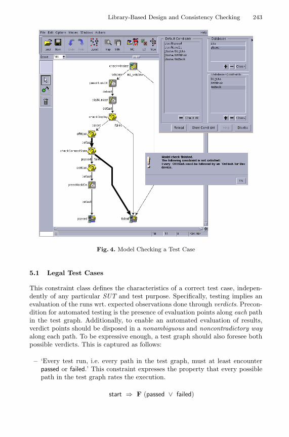
Library-Based Design and Consistency Checking 243
Fig. 4. Model Checking a Test Case
5.1 Legal Test Cases
This constraint class defines the characteristics of a correct test case, indepen-dently of any particular SUT and test purpose. Specifically, testing implies anevaluation of the runs wrt. expected observations done through verdicts. Precon-dition for automated testing is the presence of evaluation points along each pathin the test graph. Additionally, to enable an automated evaluation of results,verdict points should be disposed in a nonambiguous and noncontradictory wayalong each path. To be expressive enough, a test graph should also foresee bothpossible verdicts. This is captured as follows:
– ‘Every test run, i.e. every path in the test graph, must at least encounterpassed or failed.’ This constraint expresses the property that every possiblepath in the test graph rates the execution.
start ⇒ F (passed ∨ failed)

244 O. Niese et al.
– ‘Every test graph must contain at least one path which encounters passed.’This constraint captures the intuition that every test graph must provide thepossibility to exit successfully, i.e., with verdict passed. Since we here con-sider linear time logic, in this paper we must express this property indirectlyby disproving5
start ⇒ G (¬ passed)
– ‘Once a verdict is assigned it cannot be changed.’ This constraint ensuresthat verdict points should be disposed in a nonambiguous and noncontradic-tory way along each path, where
passed ∨ failed ⇒ < tt > G (¬passed ∨ ¬failed)
Usually, such constraints are not explicitly formulated anywhere, since they aremostly obvious for test engineers. However, being able to formulate them in anautomatically verifiable way changes this situation, because it is no longer amatter of mere understanding but of a drastically reduced search effort.
5.2 POTS Test Cases
This constraint class defines the characteristics of correct functioning of PlainOld Telephone Services (POTS), which build the basis of any CTI applicationbehaviour. This constraint class is still very general, and in practice relevantfor each specific test scenario we consider. In the following, we consider someconstraints explaining the end-user level behaviour of telephones:
– ‘Digits test blocks are only allowed to appear after a corresponding offHooktest block’, making sure that the phone is always properly initialized.
∀n. start ⇒ ( ¬digits(n)U offHook(n) )
– ‘Every offHook must be followed by an onHook for this device’.
∀n. offHook(n) ⇒ F ( onHook(n) )
– ‘An onHook can only be executed when an offHook was initiated for thisdevice before’.
∀n. start ⇒ ( ¬onHook(n)U offHook(n) )
In fact Fig. 4 demonstrates a model checker-produced counterexample forthe second property in terms of a violating path.
Other constraints of this class concern the different signalling and commu-nication channels of a modern phone with an end user: signalling via tones,5 Our model checker actually also covers the full mu-calculus and could therefore
address a direct formulation of this property.
Library-Based Design and Consistency Checking 245
messaging via display, optic signalling via LEDs, vibration alarm. They must allconvey correct and consistent information, and possible degradation of servicein exceptional cases must respect consistency and follow a set of well-definedprecedence rules. For example, tones have highest priority, and in case of furtherurgent signalling a display message may be suppressed but not overtaken.
Many other, somewhat more technical, constraints arise as soon as we con-sider also the switch side of the system. They concern, e.g.:
– details of the communication protocols which regulates the communicationbetween the switch and peripherals (here simple telephones),
– the specific kind (analog, digital) of the protocol (e.g. ISDN, X25,...)– the layer in the protocol stack– variations of the protocol implementation specific to the vendor (here, Sie-
mens), maybe even specific to single products or product lines.
One sees immediately that manageable organization of the constraints is akey characteristic of a practicable solution.
5.3 Service Specific Test Cases
Modern midrange telephone systems for private use or in small businesses al-ready include an amazing number of additional services in addition to POTS.For example: signalling of an additional incoming call (a feature known as CallWaiting), for ISDN systems the display of the caller’s number for incoming calls(Calling Number Delivery), conference calls (Three Way Calling), forwardingto other single or groups of numbers (Call Forwarding), embedded answeringmachine functionality (Voice Mail), and many more.
Testing such a telephone system means evaluating the correct behaviour ofa set of phones in the context of one or more of those activated features, whichcan be again described as a collection of sets of constraints [4,5].
5.4 SUT Specific Test Cases
Considering concrete CTI settings like the one described in Fig. 2, we addition-ally need constraints about the correct initialization and functioning
– of the single units of the SUT (e.g. single CTI applications, or the switch),– of the corresponding test tools,– and of their interplay.
To give an idea of the complexity of the testing scenarios considered in prac-tice, the concrete application already investigated in depth includes settings witha switch, up to eight phones of different nature, a complex CTI application witha server PC and a client PC serving several end-users, a running applicationsuite, consisting of five programs, where the phones and the PC clients interact,and two test tools. The scenario is described in more detail in [9].
246 O. Niese et al.
6 Test Suite Development in the Integrated TestingEnvironment
The resulting overall lifecycle for test development using the ABC-based TestCoordinator is two-dimensional: both the application and the environment cangrow and be enriched during the development process.
6.1 Test Case and Test Suite Development
Based on libraries of test blocks and constraints, an initial test graph is graphi-cally constructed via drag-and-drop from the test block palette and subsequentlyvalidated either via graph tracing or under model checking control. In discussionswith test engineers and test designers it turned out that only very few simplepatterns of constraints are required in order to express most of the desired prop-erties. Thus, end users of the testing environment should be able to input theirown constraints on the basis of very few corresponding templates without re-quiting the help of experts in temporal logic. Test suites are then composed ofsuitable sets of test cases to cover a certain application.
In the environment, distinct Constraint Libraries concern different aspects ofthe application: Figure 4, on the right, shows that the generic test library (ite)and the POTS libraries (phone) are currently loaded, and the specific constraintsfrom those libraries have been selected for checking.
Typically, a test graph is built and modified by test designers in an aspect-driven fashion: the testing expert chooses one or more constraints of interest,expressing single aspects of the test case under construction, checks online thecorrectness of the current test graph and modifies it in case of mistakes. Thiscycle is iterated until all relevant aspects have been treated. Due to the on-line verification with the model checker, constraint violations are immediatelydetected.
6.2 Strengthening the Testing Environment
The test graph and test suite development is superposed by an orthogonal pro-cess of incremental strengthening of the application-specific environment: thishappens by successively adding further test blocks and consistency constraints.Both strengthenings proceed naturally, on demand, along the evolution of needs.
Strengthening the Model. Entire new palettes of test blocks may turn out tobecome necessary when the environment or the application grow, e.g. to accom-modate new test tools or new SUT’s (e.g., peripherals to the switch, mobilephones, applications, ...). Sometimes new single test blocks may also be needede.g. when new releases of subsystems modify or extend their functionality.
New test blocks are also defined for the purpose of better test organization(when it becomes clear that certain test graph fragments have a high potentialfor reuse). The latter situation is supported by ABC’s macro facility [19], which
Library-Based Design and Consistency Checking 247
essentially allows test designers to encapsulate (fragments of) test graphs assingle, reusable test blocks. In the further development process, these blocks canbe used just as ‘ordinary’ test blocks as shown in Fig. 3 (left): the test blockmarked with ‘M’ contains the full subgraph for Led and Display checks.
Strengthening the Constraints. New constraints naturally arise when consideringsingle new aspects of the current systems, and new Constraint Libraries whenconsidering new applications or ways of interactions. Here we use SLTL con-straints to describe in an abstract and loose way single aspects of the behaviourof a complex, distributed, heterogeneous system, which we can access only in ablackbox or at best graybox fashion. This looseness is essential as most of thehardware is sealed, and most of the software is third party.
7 Conclusions
We have presented a new coarse grain approach to automated integrated testing,which combines library-based test design, incremental formalization, and library-based consistency checking via model checking. The impact of these features forthe overall test process has been illustrated along an industrial application: anautomated integrated testing environment for CTI-Systems. In fact, the gentleentry into practice due to incremental formalization was a ‘conditio sine qua non’for the acceptance of the environment, because there has been some negativeexperience with formal methods in the past. The main reason for the failure ofthe prior approaches was their need of a full (formal) description of the SUT,which does not exists. Together with the early prototyping ability of the ABC,which allowed us to present a small running application within a couple of weeks,this won overall confidence for a long-term cooperation. Now, nine months afterthe first meeting, a prototype installation is already used by test engineers inSiemens’ test laboratories.
We are convinced that our system will significantly reduce the testing effort,as already the untrained use of the only partially instantiated integrated testenvironment (ITE) led to noticeable reduction of the originally manual testingtime. We are currently enforcing both training of the testers on the ITE, andrefined instantiation with more test blocks, version information, and configura-tion constraints. This does not require any changes on the ITE itself, and weare optimistic that we will be able to give evidence in the very near future thatthese improvements indeed dramatically strengthen the impact of the ITE. Gen-eralizations of the currently considered functional tests to other forms of testinglike performance tests and stress tests are also possible, but require more effortand are planned for a successive project phase.
References
1. V. Braun, T. Margaria, B. Steffen, H. Yoo: Automatic Error Location for IN ServiceDefinition, Proc. AIN’97, 2nd Int. Workshop on Advanced Intelligent Networks,Cesena, 1997.
248 O. Niese et al.
2. J.-C. Fernandez, C. Jard, T. Jeron and C. Viho: An Experiment in AutomaticGeneration of Test Suites for Protocols with Verification Technology, Science ofComputer Programming, 29, 1997.
3. J. Hofmann: Program Dependent Abstract Interpretation, Diplomarbeit, Fakultatfur Mathematik und Informatik, Universitat Passau, August 1997.
4. B. Jonsson, T. Margaria, G. Naeser, J. Nystrom, B. Steffen: On Modelling FeatureInteractions in Telecommunications, Proc. of Nordic Workshop on ProgrammingTheory, eds. B. Victor and W. Yi, 1999.
5. B. Jonsson, T. Margaria, G. Naeser, J. Nystrom, B. Steffen: Incremental Require-ments Specification of Evolving Systems, Feature Interactions in Telecommunica-tions and Software Systems VI, eds. M. Calder and E. Magill, ISO Press, 2000.
6. T. Margaria, B. Steffen: Backtracking-free Design Planning by Automatic Synthesisin METAFrame Proc. FASE’98, Int. Conf. on Fundamental Aspects of SoftwareEngineering, Lisbon, Apr. 1998, LNCS 1382, pp.188-204, Springer Verlag.
7. Mercury Interactive: Winrunner. http://www.winrunner.com8. O. Niese, T. Margaria, M. Nagelmann, B. Steffen, G. Brune, H.-D. Ide: An open
Environment for Automated Integrated Testing, 4th Int. Conf. on Software andInternet Quality Week Europe (QWE’00), Brussels (Belgium), November 2000,CD-ROM Proccedings, pp 584-593.
9. O. Niese, M. Nagelmann, A. Hagerer, K. Strunck, W. Goerigk, A. Erochok, B.Hammelmann: Demonstration of an Automated Integrated Testing Environmentfor CTI Systems, Proc. FASE 2001, this volume. Genova (I), 2001.
10. Object Management Group: The Common Object Request Broker: Architecture andSpecification, Revision 2.3, Object Management Group, 1999.
11. The Raise Project homepage. http://dream.dai.ed.ac.uk/raise/12. Rational: The Rational Suite description. http://www.rational.com/products.13. M. Schmitt, B. Koch, J. Grabowski, and D. Hogrefe, Autolink - A Tool for Au-
tomatic and Semi-automatic Test Generation from SDL-Specifications, TechnicalReport A-98-05, Medical Univ. of Lubeck, Germany, 1998.
14. ITU-T Recommendation Z.100, CCITT specification and description language, ’93.15. Sun: Java Remote Method Invocation. http://java.sun.com/products/jdk/rmi.16. B. Steffen, T. Margaria, A. Claßen, V. Braun: Incremental Formalization: a Key
to Industrial Success, in “Software: Concepts and Tools”, Vol.17(2), pp. 78-91,Springer Verlag, July 1996.
17. B. Steffen, T. Margaria, V. Braun: The Electronic Tool Integration Platform: Con-cepts and Design Int. Journ. on Software Tools for Technology Transfer (STTT),Vol. 1 N. 1+2, Springer Verlag, November 1997, pp. 9-30.
18. B. Steffen, T. Margaria: METAFrame in Practice: Intelligent Network Service De-sign, In Correct System Design – Issues, Methods and Perspectives, LNCS 1710,Springer Verlag, 1999, pp.390-415.
19. B. Steffen, T. Margaria, V. Braun, and N. Kalt: Hierarchical service definition,Annual Review of Communication, Int. Engineering Consortium (IEC), Chicago(USA), pages 847–856, 1997.
20. C. Stirling: Modal and Temporal Logics, In Handbook of Logics in Computer Sci-ence, Vol. 2, pp. 478 – 551, Oxford Univ. Press, 1995.
21. Telelogic: Telelogic Tau. http://www.telelogic.com.22. J. Tretmans and A. Belinfante: Automatic testing with formal methods, In Eu-
roSTAR’99: 7th European Int. Conference on Software Testing, Analysis & Review.EuroStar Conferences, Galway, Ireland, November 8–12, 1999.
Demonstration of an Automated IntegratedTesting Environment for CTI Systems
Oliver Niese1, Markus Nagelmann1, Andreas Hagerer1,Klaus Kolodziejczyk-Strunck2, Werner Goerigk3,Andrei Erochok3, and Bernhard Hammelmann3
1 METAFrame Technologies GmbH, Dortmund, Germany{ONiese, MNagelmann, AHagerer}@METAFrame.de
2 HeraKom GmbH, Essen, [email protected]
3 Siemens AG, Witten, Germany{Werner.Goerigk, Andrei.Erochok, Bernhard.Hammelmann}@wit.siemens.de
1 An Integrated Testing Environment Based on ABC
We demonstrate the Integrated Testing Environment, ITE, an environment forautomated and integrated testing at system level. A companion paper [4] de-scribes the problem of systems integrated testing in its conceptual applicationmodelling focus. Here and in [5], the concept’s implementation is exemplifiedin case of automated integrated testing of a Computer Telephony Integration(CTI) system. The CTI system consists of a switch, an automatic call distribu-tor, and a suite of applications forming a call center and supporting the tasks ofa center’s human agent, e.g., applications that enable an agent to log-on/log-offat the call distributor, or to initiate conference calls with other agents.
In the ITE, each hardware and software component of the CTI system is con-trolled by its own test tool, e.g., a proprietary hardware tracer for the switch or aGUI test tool such as Rational SQA Robot [6] for the applications. Coordinatingwhich action has to be performed by which test tool is under responsibility ofthe Test Coordinator, a tool built on top of METAFrame Technologies’ AgentBuilding Center (ABC) [2], a general-purpose environment for specification andverification of complex workflows.
As outlined in the following sections, the ITE supports the design of testcases including the verification of their consistency, the interactive combinationof test cases resulting in test scenarios, and the execution of test cases and testscenarios in the heterogenous processing environment of CTI systems.
2 Design Support Features
System testing is characterized by focussing on inter-components cooperation.For the design of appropriate system-level test cases it is necessary to know whatfeatures the system provides, how to operate the system in order to stimulatea feature, and how to determine if features work. This information is gathered
H. Hussmann (Ed.): FASE 2001, LNCS 2029, pp. 249–252, 2001.c© Springer-Verlag Berlin Heidelberg 2001
250 O. Niese et al.
and after identification of the system’s controllable and observable interfaces itis transformed into a set of stimuli (inputs) and verification actions (inspectionof outputs, investigation of components’ states). For each action a test block isprepared: a name and a class characterizing the block are specified and a set offormal parameters is defined to enable a more general usage of the block. In thisway, for the CTI system to be tested a library of test blocks has been issued thatincludes test blocks representing and implementing, e.g.
Common actions. Initialization of test tools, system components, test casesand general reporting functions,
Switch-specific actions. Initialization of switches of different extensions,Call-related actions. Initiation and pick up of calls via a PBX-network or a
local switch,CTI application-related actions. Miscellaneous actions to operate a CTI
application via its graphical user interface, e.g., log-on/log-off of an agent,establish a conference party, initiate a call via a GUI, or check labels ofGUI-elements.
The library of test blocks grows dynamically whenever new actions are madeavailable.The design of test cases consists in the behaviour-oriented combination of testblocks. This combination is done graphically, i.e., icons representing test blocksare graphically stuck together to yield test graph structures that embody thetest behaviour in terms of control.
3 Verification Support Features
As explained thoroughly in [4], design of test cases is constantly accompaniedby online verification of the global correctness and consistency of the test cases’control flow logic. During the design phase, vital properties concerning the usageof parameters (local properties) and concerning the interplay between the stimuliand verification actions of a test case (global properties) can be verified. Designdecisions that conflict with the constraints and consistency conditions of theintended system are thus immediately detected.
Local properties specified imperatively are used to check that the param-eters are correctly set. Global properties concerning the interactions betweenarbitrarily distant test blocks of a test graph are expressed in a user-friendlyspecification language based on the Semantic Linear-time Temporal Logic [3],and are gathered in a constraint library accessed by the environment’s modelchecker during verification. Basic constraints have been formulated for the CTIsystem, e.g., if a test graph includes an action “hook-on”, this must be precededby an action “hook-off”.
If the model checker detects an inconsistency, a plain text explanation of theviolated constraint appears. In addition, test blocks violating a local propertyas well as paths violating a global property are marked.
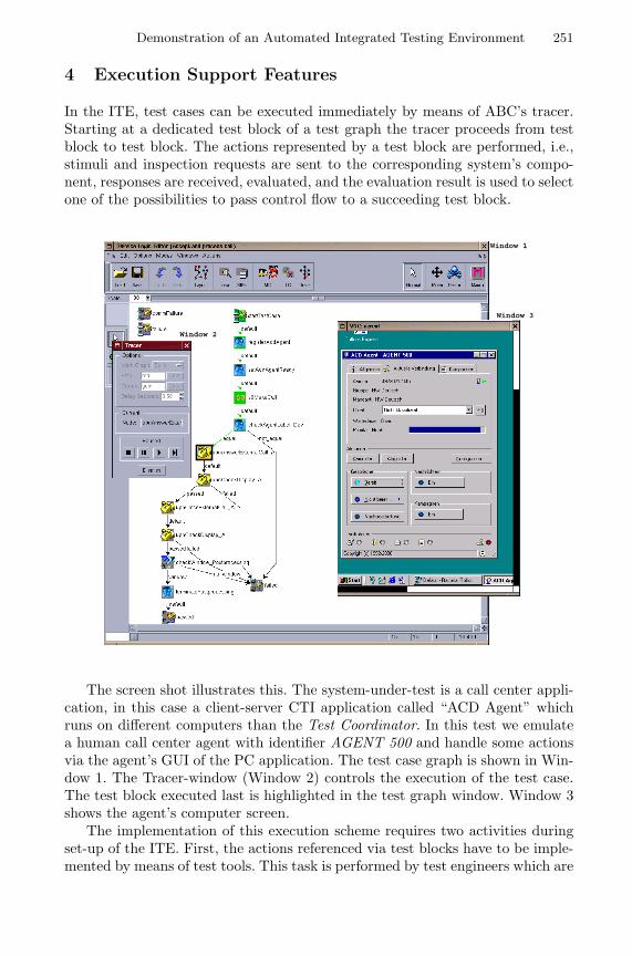
Demonstration of an Automated Integrated Testing Environment 251
4 Execution Support Features
In the ITE, test cases can be executed immediately by means of ABC’s tracer.Starting at a dedicated test block of a test graph the tracer proceeds from testblock to test block. The actions represented by a test block are performed, i.e.,stimuli and inspection requests are sent to the corresponding system’s compo-nent, responses are received, evaluated, and the evaluation result is used to selectone of the possibilities to pass control flow to a succeeding test block.
Window 3
Window 1
Window 2
The screen shot illustrates this. The system-under-test is a call center appli-cation, in this case a client-server CTI application called “ACD Agent” whichruns on different computers than the Test Coordinator. In this test we emulatea human call center agent with identifier AGENT 500 and handle some actionsvia the agent’s GUI of the PC application. The test case graph is shown in Win-dow 1. The Tracer-window (Window 2) controls the execution of the test case.The test block executed last is highlighted in the test graph window. Window 3shows the agent’s computer screen.
The implementation of this execution scheme requires two activities duringset-up of the ITE. First, the actions referenced via test blocks have to be imple-mented by means of test tools. This task is performed by test engineers which are
252 O. Niese et al.
familiar with test tools, their handling and programming. For each action, thetest engineers has to specify instructions to be executed by the test tool deter-mined to support the specific action, e.g., via recording GUI-activities. Second,specific tracer code that is assigned to the action’s test block and that will beexecuted by the tracer has to be developed. Experience with the CTI systemshows that this code can be generated automatically for most actions. Man-ual development is necessary only if the test block shall initiate the executionof multiple actions in order to meet real-time requirements or if more complexevaluation of information about a component’s state or reaction is required.
To communicate with different test tools, a flexible CORBA-based interfacehas been designed for the ITE. This interface comprises basic methods which alltest tools have to support as well as special features of tools added by means ofspecializations. In the Test Coordinator, these methods are wrapped in a uniformway and are provided for implementation of tracer code in form of adapters. Theextensibility of the ITE by additional adapters for other test tools is the key of theapproach. On the test tool’s side, the interface functionality has to be providedeither by implementing a plug-in including a CORBA object request broker orby implementing a separate server process that communicates with the test toolvia a dedicated interface (e.g., COM/DCOM).
At the moment, two test tools have been made accessible in the ITE: Ra-tional SQA Robot [6] for driving an application’s GUI and a proprietary toolHipermon developed by HeraKom GmbH. This tool controls a device simulatorthat communicates with the switch and that is able to accurately emulate calls.
Finally, when executing a test graph, a detailed protocol is prepared. For eachtest block the tracer executes, all relevant data (its execution time, its name, theversion of the files associated with the test block, the block’s parameter values,and the processed data) are written to the protocol.
References
1. S. Gladstone: Testing Computer Telephony Systems and Networks, Telecom Books,1996.
2. B. Steffen, T. Margaria, V. Braun, N. Kalt: Hierarchical Service Definition, An-nual Review of Communic., Vol. 51, Int. Engineering Consortium, Chicago, 1997,pp.847-856.
3. T. Margaria, B. Steffen: Backtracking-free Design Planning by Automatic Synthesisin METAFrame Proc. FASE’98, Int. Conf. on Fundamental Aspects of SoftwareEngineering, Lisbon, LNCS 1382, Springer Verlag, 1998, pp.188-204.
4. O. Niese, B. Steffen, T. Margaria, A. Hagerer, G. Brune, H.-D. Ide: Library-basedDesign and Consistency Checking of System-level Industrial Test Cases, FASE2001, this volume.
5. O. Niese, T. Margaria, A. Hagerer, M. Nagelmann, B. Steffen, G. Brune, H.-D. Ide:An Automated Testing Environment for CTI Systems Using Concepts for Specifi-cation and Verification of Workflows, accepted for publication in Annual Reviewof Communic., Vol. 54, Int. Engineering Consortium, Chicago, 2000.
6. Rational, Inc.: The Rational Suite description,http://www.rational.com/products.
Semantics of Architectural Specifications in CASL
Lutz Schroder1, Till Mossakowski1, Andrzej Tarlecki2,3,Bartek Klin4, and Piotr Hoffman2
1 BISS, Department of Computer Science, Bremen University2 Institute of Informatics, Warsaw University
3 Institute of Computer Science, Polish Academy of Sciences4 BRICS, Arhus University
Abstract. We present a semantics for architectural specifications inCasl, including an extended static analysis compatible with model-theoretic requirements. The main obstacle here is the lack of amalgama-tion for Casl models. To circumvent this problem, we extend the Casllogic by introducing enriched signatures, where subsort embeddings forma category rather than just a preorder. The extended model functor hasamalgamation, which makes it possible to express the amalgamabilityconditions in the semantic rules in static terms. Using these concepts,we develop the semantics at various levels in an institution-independentfashion.
1 Introduction
A common feature of present-day algebraic specification languages (see e.g.[Wir86,EM85,GHG+93,CoFI96,SW99]) is the provision of operations for build-ing large specifications in a structured fashion from smaller and simpler ones[BG77]. For the quite different purpose of describing the modular structure ofsoftware systems under development [SST92], architectural specifications havebeen introduced as a comparatively novel feature in the algebraic specificationlanguage Casl recently developed by the CoFI group [CoF,CoF99a,Mos99].
The main idea is that architectural specifications describe branching pointsin system development by indicating units (modules) to be independently de-veloped and showing how these units, once developed, are to be put togetherto produce the overall result. Semantically, units are viewed as given modelsof specifications, to be used as building blocks for models of more complexspecifications, e.g. by amalgamating units or by applying parametrized units.Architectural specifications have been introduced and motivated in [BST99].
The aim of the present paper is to outline the semantics of architecturalspecifications at various levels. We use a simple subset of Casl architecturalspecifications, which is expressive enough to study the main mechanisms andfeatures of the semantics. A crucial prerequisite for a semantics of architecturalspecifications is the amalgamation property, which allows smaller models to becombined into larger ones under statically checkable conditions. Somewhat in-formally, the amalgamation property ensures that whenever two models ‘share’
H. Hussmann (Ed.): FASE 2001, LNCS 2029, pp. 253–268, 2001.c© Springer-Verlag Berlin Heidelberg 2001
254 L. Schroder et al.
components in the intersection of their signatures, they can be unambiguouslyput together to form a model of the union of their signatures. Many standardlogical systems (like multisorted equational [EM85] and first-order logic [MT93]with the respective standard notions of model) admit amalgamation, so quiteoften this property is taken for granted in work on specification formalisms (cf.e.g. [ST88]). However, the expected amalgamation property fails to hold for thelogical system underlying Casl.
We develop a three-step semantics that circumvents this problem. The firststep is a purely model-theoretic semantics. Here, amalgamability is just requiredwhenever it is needed. This makes the definition of the semantics as straightfor-ward and permissive as possible, but leaves the task of actually checking thesemodel-theoretic requirements. Thus, the natural second step is to give a seman-tics of architectural specifications in terms of diagrams which express the sharingthat is present in the unit declarations and definitions. This allows us to reformu-late the model-theoretic amalgamability conditions in ‘almost’ static terms. Asuitable amalgamation property is needed to make the static character of theseconditions explicit. The trick used in the third step to achieve this is to embedthe Casl logic into a richer logic that does have amalgamation. This makes itpossible to restate the amalgamability conditions as entirely static factorizationproperties of signature morphisms.
These three steps of the semantics are in fact independent of the details ofthe underlying Casl logical system: we present them in the framework of anarbitrary logical system formalized as an institution [GB92]. As a result, thefactorization properties to which we reduce the amalgamation conditions arestill relatively abstract. A calculus for checking these factorization propertiesin the case of the specificic logic underlying Casl is developed in a separatepaper [KHT+].
We refer to [Mac97,AHS90] for categorical terminology left unexplained here.
2 Architectural Specifications
As indicated above, architectural specifications in Casl provide a means of stat-ing how implementation units are used as building blocks for larger components.(Dynamic interaction between modules and dynamic changes of software struc-ture are currently beyond the scope of this approach.)
Units are represented as names to which a specification is assigned. Such anamed unit is to be thought of as a given model of the specification. Units may beparametrized, where specifications are assigned to both the parameters and theresult. The result specification is required to extend the parameter specifications.A parametrized unit is to be understood as a function which, given models ofthe parameter specifications, outputs a model of the result specification; thisfunction is required to be persistent, i.e. reducing the result to the parametersignatures reproduces the parameters.
Units can be assembled via unit expressions which may contain operationssuch as renaming or hiding of symbols, amalgamation of units, and application
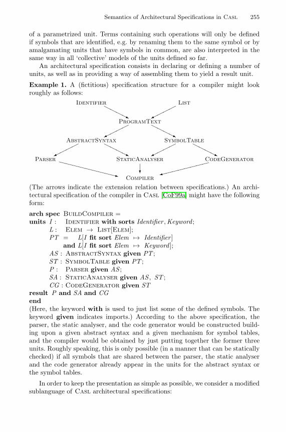
Semantics of Architectural Specifications in Casl 255
of a parametrized unit. Terms containing such operations will only be definedif symbols that are identified, e.g. by renaming them to the same symbol or byamalgamating units that have symbols in common, are also interpreted in thesame way in all ‘collective’ models of the units defined so far.
An architectural specification consists in declaring or defining a number ofunits, as well as in providing a way of assembling them to yield a result unit.
Example 1. A (fictitious) specification structure for a compiler might lookroughly as follows:
Identifier ListHHHHj �����
ProgramText
����� HHHHjAbstractSyntax SymbolTable
����� HHHHj ����� HHHHjParser StaticAnalyser CodeGeneratorXXXXXXXXXz 9��������
Compiler?
(The arrows indicate the extension relation between specifications.) An archi-tectural specification of the compiler in Casl [CoF99a] might have the followingform:
arch spec BuildCompiler =units I : Identifier with sorts Identifier ,Keyword ;
L : Elem → List[Elem];PT = L[I fit sort Elem 7→ Identifier ]
and L[I fit sort Elem 7→ Keyword ];AS : AbstractSyntax given PT ;ST : SymbolTable given PT ;P : Parser given AS ;SA : StaticAnalyser given AS , ST ;CG : CodeGenerator given ST
result P and SA and CGend(Here, the keyword with is used to just list some of the defined symbols. Thekeyword given indicates imports.) According to the above specification, theparser, the static analyser, and the code generator would be constructed build-ing upon a given abstract syntax and a given mechanism for symbol tables,and the compiler would be obtained by just putting together the former threeunits. Roughly speaking, this is only possible (in a manner that can be staticallychecked) if all symbols that are shared between the parser, the static analyserand the code generator already appear in the units for the abstract syntax orthe symbol tables.
In order to keep the presentation as simple as possible, we consider a modifiedsublanguage of Casl architectural specifications:
256 L. Schroder et al.
Architectural specifications: ASP ::= arch spec UDD∗ result T ;UDD ::= Dcl | DfnAn architectural specification consists of a list of unit declarations and defi-nitions followed by a unit result term.
Unit declarations: Dcl ::= U :SP | U :SP1τ−→SP2
A unit declaration introduces a unit name with its type, which is eithera specification or a specification of a parametrized unit, determined by aspecification of its parameter and its result, which extends the parameter viaa signature morphism τ — we assume that the definition of specifications andsome syntactic means to present signature morphisms are given elsewhere.(By resorting to explicit signature morphisms, we avoid having to discussthe details of signature inclusions.)
Unit definitions: Dfn ::= U = TA unit definition introduces a (non-parametrized) unit and gives its valueby a unit term.
Unit terms: T ::= U | U [T fit σ] | T1 with σ1 and T2 with σ2A unit term is either a (non-parametrized) unit name, or a unit applicationwith an argument that fits via a signature morphism σ, or an amalgamationof units via signature morphisms σ1 and σ2. We require that σ1 and σ2 forman episink (have a common target signature and are jointly epi); we thusslightly generalize the amalgamation operation of Casl here, again avoidingthe need to present the details of signature unions (cf. [Mos00]).
Imports as used in Example 1 can be regarded as syntactical sugar for aparametrized unit which is instantiated only once.
3 Institutions and Amalgamation
The semantic considerations ahead rely on the notion of institution [GB92]. Aninstitution I consists of a category Sign of signatures, a model functor
Mod : Signop → CAT,
where CAT denotes the quasicategory of categories and functors [AHS90], andfurther components which formalize sentences and satisfaction. In this context,we need only the model functor. For a signature Σ, Mod(Σ) is referred to asthe category of models for Σ, and for a signature morphism σ : Σ1 → Σ2,Mod(σ) : Mod(Σ2) → Mod(Σ1) is called the reduct functor. Mod(σ)(M) isoften written as M |σ.
A cocone for a diagram in Sign is called amalgamable if it is mapped to alimit under Mod. I has the (finite) amalgamation property if (finite) colimitcocones are amalgamable, i.e. if Mod preserves (finite) limits.
The underlying logic of Casl is formalized by the institution SubPCFOL(for ‘subsorted partial first order logic with sort generation constraints’); theassociated signature category is denoted by CASLsign [CoF99b,Mos]. As men-tioned above, SubPCFOL does not have the finite amalgamation property (cf.Example 3).
Semantics of Architectural Specifications in Casl 257
4 Basic Architectural Semantics
We now proceed to give a basic semantics of the architectural language definedin Section 2 similarly as for full Casl [CoF99b]. We use the natural semanticsstyle, by presenting rules for the static semantics, with judgements written as
` � , and for the model semantics, with judgements written as `⇒ (where the blank spaces represent, in this order, a context of some
kind, a syntactical object, and a semantical object). We simplify the rules of themodel semantics by assuming a successful application of the corresponding rulesof the static semantics, with symbols introduced there available for the modelsemantics as well. Moreover, we will regard Mod(Σ) as a class of models forthe purposes of the model semantics.
The static semantics for an architectural specification yields a static contextdescribing the signatures of the units declared or defined within the specificationand the signature of its result unit. Thus, a static context Cst = (Pst ,Bst)consists of two finite maps: Pst from unit names to parametrized unit signatures,which in turn are signature morphisms τ : Σ1 → Σ2, and Bst from unit names tosignatures (for non-parametrized units). We require the domains of Pst and Bstto be disjoint. The empty static context that consists of two empty maps willbe written as C ∅
st . Given an initial static context, the static semantics for unitdeclarations and definitions produces a static context by adding the signaturefor the newly introduced unit, and the static semantics for unit terms determinesthe signature for the resulting unit.
In terms of the model semantics, a (non-parametrized) unit M over a sig-nature Σ is just a model M ∈ Mod(Σ). A parametrized unit F over aparametrized unit signature τ : Σ1 → Σ2 is a persistent partial functionF : Mod(Σ1) ⇀ Mod(Σ2) (i.e. F (M)|τ = M for each M ∈ dom F ); thedomain of F is determined by the argument specification.
The model semantics for architectural specifications yields a unit context C,which is a class of unit environments E, i.e. finite maps from unit names to unitsas introduced above, and a unit evaluator UEv , a function that yields a unit whengiven a unit environment in the unit context. The unconstrained unit context,which consists of all environments, will be written as C∅. The model semanticsfor unit declarations and definitions enlarges unit contexts as expected. Finally,the model semantics for a unit term yields a unit evaluator, given a unit context.
The complete semantics is given in Figure 1, where we use some auxiliarynotation: given a unit context C, a unit name U and a class of units V,
C × {U 7→ V} := {E + {U 7→ V } | E ∈ C,V ∈ V},where E + {U 7→ V } maps U to V and otherwise behaves like E . Moreover,given a unit context C, a unit name U and a unit evaluator UEv ,
C ⊗ {U 7→ UEv} := {E + {U 7→ UEv(E )} | E ∈ C}.We assume that the signature category is equipped with a partial selection
of pushouts (σR : Σ1 → ΣR, τR : Σ2 → ΣR, ΣR) for spans (σ : Σ → Σ1, τ : Σ →
258 L. Schroder et al.
Σ2) of signature morphisms (where (σ, τ) may fail to have a selected pushouteven when has a pushout). In Casl, the selected pushouts would be the ones thatcan be expressed by signature translations and simple syntactic unions. We alsoassume that the semantics for specifications is given elsewhere, with ` SP � Σand ` SP ⇒ M implying M ⊆ Mod(Σ).
Perhaps the only points in the semantics that require some discussion arethe rules of the model semantics for unit application and amalgamation.
In the rule for application of a parametrized unit U , we have the requirement
for each E ∈ C,UEv(E )|σ ∈ domE (U ),
where UEv denotes the unit evaluator and C the unit context. This is just thestatement that the fitting morphism correctly ‘fits’ the actual parameter as anargument for the parametrized unit. To verify this requirement, one typicallyhas to prove that σ is a specification morphism from the argument specificationto the specification of the actual parameter (which, in the general case, has tobe constructed from the relevant unit term by means of a suitable calculus). Ingeneral, this requires some semantic or proof-theoretic reasoning.
The situation is different with the conditions marked with a (∗) in Figure 1.These ‘amalgamability conditions’ are typically expected to be at least par-tially discharged by some static analysis — similarly to the sharing require-ments present in some programming languages (cf. e.g. Standard ML [Pau96]).Of course, the basic static analysis given here is not suited for this purpose, sinceno information is stored about dependencies between units. This will be takencare of in the second level of the semantics.
5 Extended Static Architectural Semantics
As a solution to the problem just outlined, we now introduce an extended staticanalysis that keeps track of sharing among the units by means of a diagram ofsignatures; the idea here is that a symbol shares with any symbol to which it ismapped under some morphism in the diagram.
For our purposes, it suffices to regard a diagram as a graph morphism D :I → Sign, where I is a directed graph called the scheme of the diagram. We usecategorical terminology for I, i.e. we call its nodes ‘objects’, its edges ‘morphisms’etc., and we write Ob I for the set of objects.
We will use the usual notion of extension for diagrams. Two diagrams D1, D2disjointly extend D if both D1 and D2 extend D and moreover, the intersectionof their schemes is the scheme of D. If this is the case then the union D1 ∪ D2is well-defined.
The judgements of the extended static semantics are written as ` �� .Most of the rules differ only formally from the rules for the static semantics; theessential differences are in the rules for unit terms. The extended static semanticsadditionally carries around the said diagram of signatures. Signatures for unitterms are associated to distinguished objects in the diagram scheme.
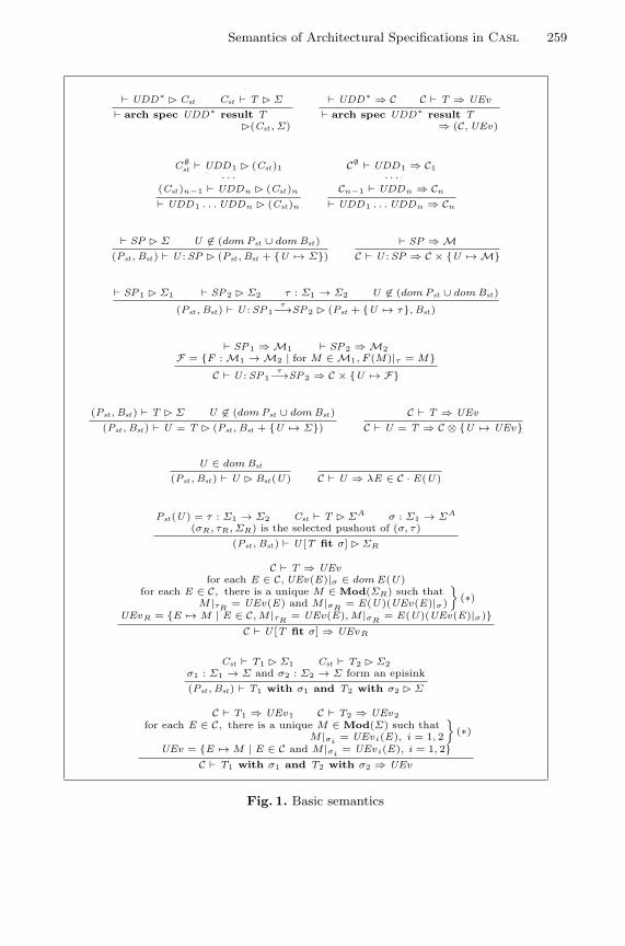
Semantics of Architectural Specifications in Casl 259
` UDD∗ � Cst Cst ` T � Σ
` arch spec UDD∗ result T�(Cst , Σ)
` UDD∗ ⇒ C C ` T ⇒ UEv` arch spec UDD∗ result T
⇒ (C, UEv)
C∅st ` UDD1 � (Cst )1
· · ·(Cst )n−1 ` UDDn � (Cst )n
` UDD1 . . . UDDn � (Cst )n
C∅ ` UDD1 ⇒ C1· · ·
Cn−1 ` UDDn ⇒ Cn
` UDD1 . . . UDDn ⇒ Cn
` SP � Σ U 6∈ (dom Pst ∪ dom Bst )(Pst , Bst ) ` U :SP � (Pst , Bst + {U 7→ Σ})
` SP ⇒ MC ` U :SP ⇒ C × {U 7→ M}
` SP1 � Σ1 ` SP2 � Σ2 τ : Σ1 → Σ2 U 6∈ (dom Pst ∪ dom Bst )
(Pst , Bst ) ` U :SP1τ−→SP2 � (Pst + {U 7→ τ}, Bst )
` SP1 ⇒ M1 ` SP2 ⇒ M2F = {F : M1 → M2 | for M ∈ M1, F (M)|τ = M}
C ` U :SP1τ−→SP2 ⇒ C × {U 7→ F}
(Pst , Bst ) ` T � Σ U 6∈ (dom Pst ∪ dom Bst )(Pst , Bst ) ` U = T � (Pst , Bst + {U 7→ Σ})
C ` T ⇒ UEvC ` U = T ⇒ C ⊗ {U 7→ UEv}
U ∈ dom Bst
(Pst , Bst ) ` U � Bst (U ) C ` U ⇒ λE ∈ C · E(U )
Pst (U ) = τ : Σ1 → Σ2 Cst ` T � ΣA σ : Σ1 → ΣA
(σR, τR, ΣR) is the selected pushout of (σ, τ)(Pst , Bst ) ` U [T fit σ] � ΣR
C ` T ⇒ UEvfor each E ∈ C, UEv(E)|σ ∈ dom E(U )
for each E ∈ C, there is a unique M ∈ Mod(ΣR) such thatM |τR
= UEv(E) and M |σR= E(U )(UEv(E)|σ)
}(∗)
UEvR = {E 7→ M | E ∈ C, M |τR= UEv(E), M |σR
= E(U )(UEv(E)|σ)}C ` U [T fit σ] ⇒ UEvR
Cst ` T1 � Σ1 Cst ` T2 � Σ2σ1 : Σ1 → Σ and σ2 : Σ2 → Σ form an episink(Pst , Bst ) ` T1 with σ1 and T2 with σ2 � Σ
C ` T1 ⇒ UEv1 C ` T2 ⇒ UEv2for each E ∈ C, there is a unique M ∈ Mod(Σ) such that
M |σi= UEvi(E), i = 1, 2
}(∗)
UEv = {E 7→ M | E ∈ C and M |σi= UEvi(E), i = 1, 2}
C ` T1 with σ1 and T2 with σ2 ⇒ UEv
Fig. 1. Basic semantics
260 L. Schroder et al.
Explicitly, an extended static context Cst = (Pst ,Bst , D) consists of a map Pstthat assigns unit signatures to parametrized unit names (as before), a signaturediagram D, and a map Bst that assigns objects of the diagram scheme to (non-parametrized) unit names. As before, we require that the domains of Pst and Bstare disjoint. Cst determines a static context ctx (Cst) formed by extracting thesignature information for non-parametrized unit names from the diagram andforgetting the diagram itself. The empty extended static context, which consistsof two empty maps and the empty diagram, is written as C∅
st . The extended staticsemantics for unit declarations and definitions expands the given extended staticcontext; for unit terms, it extends the signature diagram and indicates an objectin the scheme that represents the result.
The diagrams enable us to restate the amalgamability conditions in a staticway: for any diagram D : I → Sign, 〈Mi〉i∈Ob I is called consistent with Dif for each i ∈ Ob I, each Mi ∈ Mod(D(i)), and for each m : i → j in I,Mi = Mj |D(m). We denote the class of all model families that are consistentwith D by Mod(D). Then D ensures amalgamability for D′, where D′ extendsD, if any family in Mod(D) can be uniquely extended to a family in Mod(D′).
Although we have formulated this property in terms of model families, itis essentially static: the class of model families considered is not restricted byaxioms, but only by morphisms between signatures. The static nature of thiscondition will be made explicit in Section 7.
The rules of the extended static semantics are listed in Figure 2; given theheuristics provided above, they should be largely self-explanatory. However, therelationship between the basic static and model semantics and the extendedstatic semantics requires a few comments.
Since, as stated at the end of the previous section, the correctness conditionfor arguments of parametrized units cannot be disposed of statically, one cannotexpect that the extended static semantics is stronger than the model semantics,i.e. that its successful application guarantees that the model sematics will succeedas well. However, this is almost true in the sense that argument fitting is theonly point that is left entirely to the model semantics. Formally, this can becaptured by the statement that, assuming a successful run of the extended staticsemantics, the conditions marked with a (∗) in the rules of the model semantics(cf. Figure 1) can be removed.
Calling the combination of the extended static semantics and the thus sim-plified model semantics extended semantics, we now indeed have:
Theorem 2. If the extended semantics of an architectural specification is de-fined, then the basic semantics is defined as well and yields the same result.
Of course, no completeness can be expected here: even if the basic semantics issuccessful for a given phrase, the extended semantics may fail. This happens if themodel-theoretic amalgamability conditions hold due to axioms in specificationsrather than due to static properties of the involved constructions.
An additional source of failures of the extended static semantics is that wehave deliberately chosen a so-called generative static analysis: the results of ap-plications of parametrized units ‘share’ with other units in the signature diagram
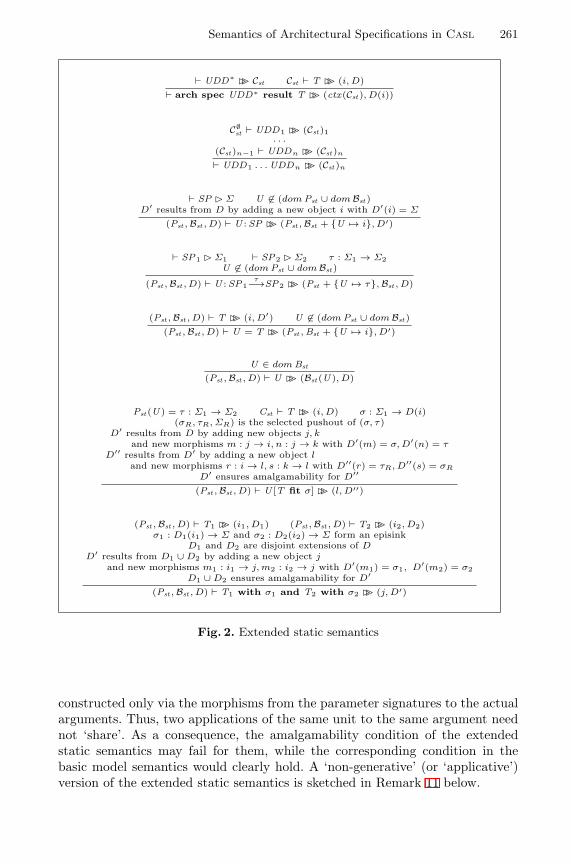
Semantics of Architectural Specifications in Casl 261
` UDD∗ �� Cst Cst ` T �� (i, D)` arch spec UDD∗ result T �� (ctx(Cst ), D(i))
C∅st ` UDD1 �� (Cst )1
· · ·(Cst )n−1 ` UDDn �� (Cst )n
` UDD1 . . . UDDn �� (Cst )n
` SP � Σ U 6∈ (dom Pst ∪ dom Bst )D′ results from D by adding a new object i with D′(i) = Σ
(Pst , Bst , D) ` U :SP �� (Pst , Bst + {U 7→ i}, D′)
` SP1 � Σ1 ` SP2 � Σ2 τ : Σ1 → Σ2U 6∈ (dom Pst ∪ dom Bst )
(Pst , Bst , D) ` U :SP1τ−→SP2 �� (Pst + {U 7→ τ}, Bst , D)
(Pst , Bst , D) ` T �� (i, D′) U 6∈ (dom Pst ∪ dom Bst )(Pst , Bst , D) ` U = T �� (Pst , Bst + {U 7→ i}, D′)
U ∈ dom Bst
(Pst , Bst , D) ` U �� (Bst (U ), D)
Pst (U ) = τ : Σ1 → Σ2 Cst ` T �� (i, D) σ : Σ1 → D(i)(σR, τR, ΣR) is the selected pushout of (σ, τ)
D′ results from D by adding new objects j, kand new morphisms m : j → i, n : j → k with D′(m) = σ, D′(n) = τ
D′′ results from D′ by adding a new object land new morphisms r : i → l, s : k → l with D′′(r) = τR, D′′(s) = σR
D′ ensures amalgamability for D′′
(Pst , Bst , D) ` U [T fit σ] �� (l, D′′)
(Pst , Bst , D) ` T1 �� (i1, D1) (Pst , Bst , D) ` T2 �� (i2, D2)σ1 : D1(i1) → Σ and σ2 : D2(i2) → Σ form an episink
D1 and D2 are disjoint extensions of DD′ results from D1 ∪ D2 by adding a new object j
and new morphisms m1 : i1 → j, m2 : i2 → j with D′(m1) = σ1, D′(m2) = σ2D1 ∪ D2 ensures amalgamability for D′
(Pst , Bst , D) ` T1 with σ1 and T2 with σ2 �� (j, D′)
Fig. 2. Extended static semantics
constructed only via the morphisms from the parameter signatures to the actualarguments. Thus, two applications of the same unit to the same argument neednot ‘share’. As a consequence, the amalgamability condition of the extendedstatic semantics may fail for them, while the corresponding condition in thebasic model semantics would clearly hold. A ‘non-generative’ (or ‘applicative’)version of the extended static semantics is sketched in Remark 11 below.
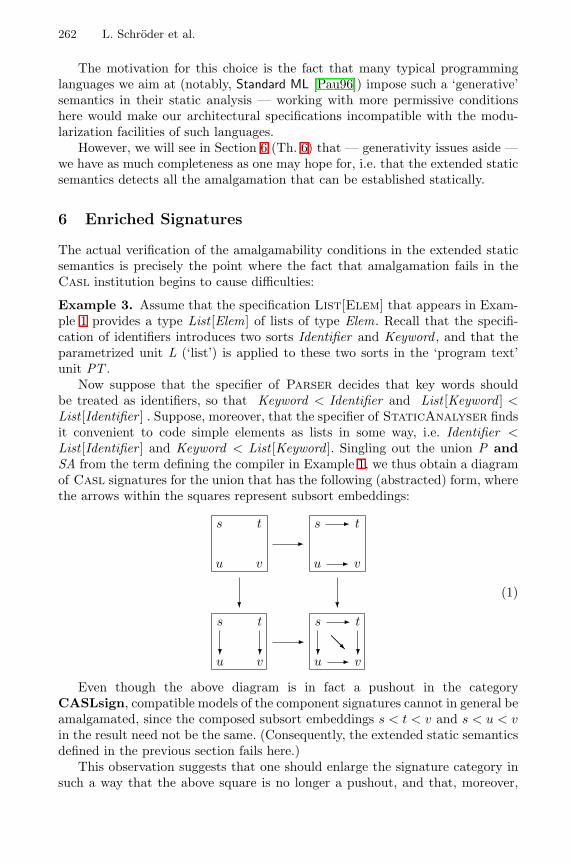
262 L. Schroder et al.
The motivation for this choice is the fact that many typical programminglanguages we aim at (notably, Standard ML [Pau96]) impose such a ‘generative’semantics in their static analysis — working with more permissive conditionshere would make our architectural specifications incompatible with the modu-larization facilities of such languages.
However, we will see in Section 6 (Th. 6) that — generativity issues aside —we have as much completeness as one may hope for, i.e. that the extended staticsemantics detects all the amalgamation that can be established statically.
6 Enriched Signatures
The actual verification of the amalgamability conditions in the extended staticsemantics is precisely the point where the fact that amalgamation fails in theCasl institution begins to cause difficulties:
Example 3. Assume that the specification List[Elem] that appears in Exam-ple 1 provides a type List [Elem] of lists of type Elem. Recall that the specifi-cation of identifiers introduces two sorts Identifier and Keyword , and that theparametrized unit L (‘list’) is applied to these two sorts in the ‘program text’unit PT .
Now suppose that the specifier of Parser decides that key words shouldbe treated as identifiers, so that Keyword < Identifier and List [Keyword ] <List [Identifier ] . Suppose, moreover, that the specifier of StaticAnalyser findsit convenient to code simple elements as lists in some way, i.e. Identifier <List [Identifier ] and Keyword < List [Keyword ]. Singling out the union P andSA from the term defining the compiler in Example 1, we thus obtain a diagramof Casl signatures for the union that has the following (abstracted) form, wherethe arrows within the squares represent subsort embeddings:
s t
u v
-s - t
u - v
s t
u?
v?
?
-s - t
@@Ru? - v
?
?(1)
Even though the above diagram is in fact a pushout in the categoryCASLsign, compatible models of the component signatures cannot in general beamalgamated, since the composed subsort embeddings s < t < v and s < u < vin the result need not be the same. (Consequently, the extended static semanticsdefined in the previous section fails here.)
This observation suggests that one should enlarge the signature category insuch a way that the above square is no longer a pushout, and that, moreover,
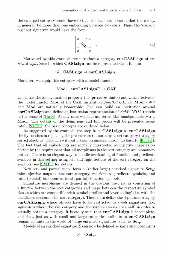
Semantics of Architectural Specifications in Casl 263
the enlarged category would have to take the fact into account that there may,in general, be more than one embedding between two sorts. Thus, the ‘correct’pushout signature would have the form
s - t
@@R@@Ru? - v
?. (2)
Motivated by this example, we introduce a category enrCASLsign of en-riched signatures in which CASLsign can be represented via a functor
Φ : CASLsign → enrCASLsign.
Moreover, we equip this category with a model functor
Mode : enrCASLsignop → CAT
which has the amalgamation property (i.e. preserves limits) and which ‘extends’the model functor Mod of the Casl institution SubPCFOL, i.e. Mode ◦ Φop
and Mod are naturally isomorphic. One can build an institution aroundenrCASLsign and define an institution representation of SubPCFOL thereinin the sense of [Tar96]. At any rate, we shall use terms like ‘amalgamable’ w.r.t.Mode. The details of the definitions and full proofs will be presented sepa-rately [SMT+]; the basic concepts are outlined below.
As suggested by the example, the step from CASLsign to enrCASLsignchiefly consists in replacing the preorder on the sorts by a sort category (categorysorted algebras, although without a view on amalgamation, go back to [Rey80]).The fact that all embeddings are actually interpreted as injective maps is re-flected by the requirement that all morphisms in the sort category are monomor-phisms. There is an elegant way to handle overloading of function and predicatesymbols in this setting using left and right actions of the sort category on thesymbols; see [SMT+] for details.
Now sets and partial maps form a (rather large) enriched signature Setp:take injective maps as the sort category, relations as predicate symbols, andtotal (partial) functions as total (partial) function symbols.
Signature morphisms are defined in the obvious way, i.e. as consisting ofa functor between the sort categories and maps between the respective symbolclasses which are compatible with symbol profiles and ‘overloading’ (i.e. with thementioned actions of the sort category). These data define the signature categoryenrCASLsign, where objects have to be restricted to small signatures (i.e.signatures where the sort category and the symbol classes are small) in order toactually obtain a category. It is easily seen that enrCASLsign is cocomplete,and that, just as with small and large categories, colimits in enrCASLsignremain colimits in the world of ‘large enriched signatures’ such as Setp.
Models of an enriched signature Σ can now be defined as signature morphisms
Σ → Setp.
264 L. Schroder et al.
Model morphisms are defined by the standard homomorphy conditions. Signa-ture morphisms induce reduct functors in the opposite direction via composition;this defines the model functor Mode.
The functor Φ : CASLsign → enrCASLsign acts on Casl signatures byinterpreting the sort preorder as a thin category (and by completing the symbolsets as required by the mentioned actions; cf. [SMT+]).
Now it is easily verified that one indeed has a natural isomorphism Mode ◦Φop → Mod. Thus:
Proposition 4. A cocone in CASLsign is amalgamable in SubPCFOL iff itsimage under Φ is amalgamable w.r.t. Mode.
Thanks to the way models are defined, amalgamation for enriched signaturescomes almost for free: models are given by a representable functor (namely,hom( ,Setp)), which automatically preserves limits; little more considerationhas to be given to model morphisms. Explicitly:
Proposition 5. Mode has the amalgamation property.
Moreover, the ‘converse’ of amalgamation holds as well:
Theorem 6. Mode reflects isomorphisms.
Since Mode preserves limits and enrCASLsignop is complete, it follows thatMode reflects limits. Explicitly, a cocone in enrCASLsign is amalgamableiff it is a colimit. This is essentially what is meant by the ‘optimal degree ofcompleteness’ statement in Section 5: a cocone in CASLsign is amalgamableiff it is mapped to a colimit under Φ.
7 Static Analysis via Enriched Signatures
We are now ready to translate the amalgamation conditions that appear inthe rules for unit application and amalgamation in the extended static se-mantics to entirely static conditions. To this end, we assume that we havea cocomplete category EnrSign of enriched signatures with a model functorMode : EnrSignop → CAT which has the amalgamation property and reflectsisomorphisms (limits) and a functor Φ : Sign → EnrSign such that Mode ◦Φop
and Mod : Signop → CAT are naturally isomorphic. For the Casl institutionSubPCFOL, these data have been constructed above.
Recall that the said amalgamation conditions required diagrams to ensureamalgamability for certain extensions, which was defined as unique extendabilityof consistent families of models. By the assumption on the model functors, thisrequirement is equivalent to the corresponding statement for the translationsof the diagrams via Φ. By the amalgamation property, a consistent family ofmodels for a diagram D in EnrSign is essentially the same as a model of thecolimit signature colim D. Thus we have
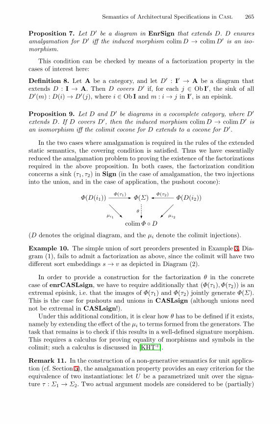
Semantics of Architectural Specifications in Casl 265
Proposition 7. Let D′ be a diagram in EnrSign that extends D. D ensuresamalgamation for D′ iff the induced morphism colim D → colim D′ is an iso-morphism.
This condition can be checked by means of a factorization property in thecases of interest here:
Definition 8. Let A be a category, and let D′ : I′ → A be a diagram thatextends D : I → A. Then D covers D′ if, for each j ∈ Ob I′, the sink of allD′(m) : D(i) → D′(j), where i ∈ Ob I and m : i → j in I′, is an episink.
Proposition 9. Let D and D′ be diagrams in a cocomplete category, where D′
extends D. If D covers D′, then the induced morphism colim D → colim D′ isan isomorphism iff the colimit cocone for D extends to a cocone for D′.
In the two cases where amalgamation is required in the rules of the extendedstatic semantics, the covering condition is satisfied. Thus we have essentiallyreduced the amalgamation problem to proving the existence of the factorizationsrequired in the above proposition. In both cases, the factorization conditionconcerns a sink (τ1, τ2) in Sign (in the case of amalgamation, the two injectionsinto the union, and in the case of application, the pushout cocone):
Φ(D(i1))Φ(τ1)- Φ(Σ) �Φ(τ2)
Φ(D(i2))
@@µi1 R �
�µi2
colim Φ ◦ D
θ
?
........
(D denotes the original diagram, and the µi denote the colimit injections).
Example 10. The simple union of sort preorders presented in Example 3, Dia-gram (1), fails to admit a factorization as above, since the colimit will have twodifferent sort embeddings s → v as depicted in Diagram (2).
In order to provide a construction for the factorization θ in the concretecase of enrCASLsign, we have to require additionally that (Φ(τ1), Φ(τ2)) is anextremal episink, i.e. that the images of Φ(τ1) and Φ(τ2) jointly generate Φ(Σ).This is the case for pushouts and unions in CASLsign (although unions neednot be extremal in CASLsign!).
Under this additional condition, it is clear how θ has to be defined if it exists,namely by extending the effect of the µi to terms formed from the generators. Thetask that remains is to check if this results in a well-defined signature morphism.This requires a calculus for proving equality of morphisms and symbols in thecolimit; such a calculus is discussed in [KHT+].
Remark 11. In the construction of a non-generative semantics for unit applica-tion (cf. Section 5), the amalgamation property provides an easy criterion for theequivalence of two instantiations: let U be a parametrized unit over the signa-ture τ : Σ1 → Σ2. Two actual argument models are considered to be (partially)
266 L. Schroder et al.
equivalent if they reduce (via fitting morphisms σi : Σ1 → D(ji), i = 1, 2, whereD denotes the present context diagram) to the same model of the parameter sig-nature Σ1. This will be the case for all pairs of models that appear in consistentfamilies for D if
µj1 ◦ Φ(σ1) = µj2 ◦ Φ(σ2),
where µ is the colimit cocone for Φ ◦ D. In this case, we can use the same edgeof the diagram scheme to represent τ in both applications of U ; this has theeffect that the two results with signatures Σ1
R and Σ2R share to exactly the right
degree via the maps Σ2 → ΣiR, i = 1, 2, that appear in the defining pushouts.
8 Conclusions and Future Work
We have presented and discussed the semantics of a small and modified butquite representative subset of Casl architectural specifications in an institution-independent way. Besides the basic static and model semantics, we have laidout an extended static analysis, where sharing information between models isstored as a diagram of signatures. This has allowed us to formulate the requiredamalgamability conditions ‘almost’ statically, i.e. without referring to particularmodels constructed. In institutions with amalgamation, these conditions can bereplaced by literally static ones; this may require representing the given institu-tion in one that has the amalgamation property.
We have demonstrated how such a representation can be defined for the stan-dard Casl institution; the main point here was that one has to admit categoriesof subsort embeddings instead of just preorders in the signatures. Computa-tional aspects of the amalgamability conditions for this specific institution arediscussed separately [KHT+]. It is known that these conditions are in generalundecidable. However, decision procedures can be developed for important spe-cial cases; for instance, orders (rather than preorders) of sorts admit decidingthe amalgamability conditions by a polynomial algorithm [Kli00]. For the gen-eral case, it seems that an approximative algorithm that restricts the length of‘cells’ involved in the proofs will suffice in practically relevant cases.
The technique for the extended static analysis with colimits of enriched sig-natures providing a way to statically reformulate amalgamability conditions isgeneral enough to be readily available for other design specification frameworkswhere amalgamation causes problems. In fact, we conjecture that any institutioncan be canonically extended to an institution with the amalgamation propertyby adding formal colimits of signatures.
The work presented here is independent of the logical structure of institu-tions — sentences and satisfaction do not play any explicit role here (except forbeing used implicitly in basic specifications, of course). However, the sentencesbecome relevant as soon as we discuss further issues of verification in architec-tural specifications (represented here by the remaining fitting condition in thesemantics of unit applications). As proposed in [Hof00], formal proof obligationscan be extracted from such conditions using colimits of specification diagrams,
Semantics of Architectural Specifications in Casl 267
but only if the underlying institution has the amalgamation property. The tech-nique proposed here should allow us to circumvent this requirement: specificationdiagrams can be translated to the enriched signature category and put togetherthere, opening a way also for the development of tools supporting validation andverification of Casl (architectural) specifications.
Acknowledgements. Partial support by the CoFI Working Group (ESPRITWG 29432) is gratefully acknowledged, as well as the work of the CoFI Lan-guage and Semantics Task Groups. Moreover, we wish to thank Michel Bidoitand Donald Sannella for collaboration on architectural specifications and MauraCerioli for pointing out the lack of amalgamation for Casl models.
References
[CoFI96] CoFI. Catalogue of existing frameworks. Catalogue.html, in [CoF], 1996.[AHS90] J. Adamek, H. Herrlich, and G. E. Strecker. Abstract and Concrete Cat-
egories. Wiley Interscience, New York, 2nd edition, 1990.[BG77] R. M. Burstall and J. A. Goguen. Putting theories together to make
specifications. In Proc. 5th Intl. Joint Conf. on Artificial Intelligence,pages 1045–1058. Carnegie-Mellon University, 1977.
[BST99] M. Bidoit, D. Sannella, and A. Tarlecki. Architectural specificationsin Casl. In 7th Intl. Conference on Algebraic Methodology and Soft-ware Technology (AMAST’98), volume 1548 of LNCS, pages 341–357.Springer, 1999.
[CoF] CoFI. The Common Framework Initiative for algebraic specification anddevelopment, electronic archives. Notes and Documents accessible byWWW1 and FTP2.
[CoF99a] CoFI Language Design Task Group. Casl – The CoFI Algebraic Speci-fication Language – Summary, version 1.0. Documents/CASL/Summary,in [CoF], July 1999.
[CoF99b] CoFI Semantics Task Group. Casl – The CoFI Algebraic SpecificationLanguage – Semantics. Note S-9 (version 0.96), in [CoF], July 1999.
[EM85] H. Ehrig and B. Mahr. Fundamentals of Algebraic Specification 1. Equa-tions and Initial Semantics. Springer, 1985.
[GB92] J. Goguen and R. Burstall. Institutions: Abstract model theory for spec-ification and programming. Journal of the Association for ComputingMachinery, 39:95–146, 1992.
[GHG+93] J. V. Guttag, J. J. Horning, S. J. Garland, K. D. Jones, A. Modet,and J. M. Wing. Larch: Languages and Tools for Formal Specification.Springer, 1993.
[Hof00] P. Hoffman. Semantics of architectural specifications (in Polish). Master’sthesis, Warsaw University, 2000.
[KHT+] B. Klin, P. Hoffman, A. Tarlecki, T. Mossakowski, and L. Schroder.Checking amalgamability conditions for Casl architectural specifica-tions. Work in progress; see also [Kli00].
1 http://www.brics.dk/Projects/CoFI2 ftp://ftp.brics.dk/Projects/CoFI
268 L. Schroder et al.
[Kli00] B. Klin. An implementation of static semantics for architectural specifi-cations in Casl (in Polish). Master’s thesis, Warsaw University, 2000.
[Mac97] S. Mac Lane. Categories for the Working Mathematician. Springer,Berlin, 2nd edition, 1997.
[Mos] T. Mossakowski. Relating Casl with other specification languages: theinstitution level. Theoretical Computer Science. To appear.
[Mos99] P. D. Mosses. Casl: A guided tour of its design. In 13th Workshopon Abstract Datatypes WADT 98, volume 1589 of LNCS, pages 216–240.Springer, 1999.
[Mos00] T. Mossakowski. Specification in an arbitrary institution with symbols. In14th Workshop on Abstract Datatypes WADT 99, volume 1827 of LNCS,pages 252–270. Springer, 2000.
[MT93] K. Meinke and J. V. Tucker, editors. Many-sorted Logic and its Applica-tions. Wiley, 1993.
[Pau96] L. C. Paulson. ML for the Working Programmer. Cambridge UniversityPress, New York, 2nd edition, 1996.
[Rey80] J. C. Reynolds. Using category theory to design implicit conversionsand generic operators. In Semantics-Directed Compiler Generation, vol-ume 94 of LNCS, pages 211–258. Springer, 1980.
[SMT+] L. Schroder, T. Mossakowski, A. Tarlecki, P. Hoffman, and B. Klin. Amal-gamation via enriched signatures. Work in progress.
[SST92] D. Sannella, S. Soko lowski, and A. Tarlecki. Towards formal develop-ment of programs from algebraic specifications: Parameterisation revis-ited. Acta Informatica, 29:689–736, 1992.
[ST88] D. Sannella and A. Tarlecki. Specifications in an arbitrary institution.Information and Computation, 76:165–210, 1988.
[SW99] D. Sannella and M. Wirsing. Specification languages. In A. Astesiano,H.-J. Kreowski, and B. Krieg-Bruckner, editors, Algebraic Foundationsof Systems Specifications, pages 243–272. Springer, 1999.
[Tar96] A. Tarlecki. Moving between logical systems. In 11th Workshop onSpecification of Abstract Data Types, volume 1130 of LNCS, pages 478–502. Springer, 1996.
[Wir86] M. Wirsing. Structured algebraic specifications: A kernel language. The-oretical Computer Science, 42:123–249, 1986.
Extending Development Graphs with Hiding
Till Mossakowski1, Serge Autexier2, and Dieter Hutter3
1 BISS, Dept. of Computer Science, University of Bremen, P.O. Box 330 440,D 28334 Bremen, [email protected], Fax: +49 421 218 3054
2 FR 6.2 Informatik, Saarland University, P.O. Box 15 11 50, D 66041 Saarbrucken,[email protected], Fax: +49 681 302 2235
3 DKFI GmbH, Stuhlsatzenhausweg 3, D 66123 Saarbrucken, [email protected],Fax: +49 681 302 2235
Abstract. Development graphs are a tool for dealing with structuredspecifications in a formal program development in order to ease the man-agement of change and reusing proofs. In this work, we extend develop-ment graphs with hiding (e.g. hidden operations). Hiding is a particularlydifficult to realize operation, since it does not admit such a good decom-position of the involved specifications as other structuring operationsdo. We develop both a semantics and proof rules for development graphswith hiding. The rules are proven to be sound, and also complete relativeto an oracle for conservative extensions. We also show that an absolutecomplete set of rules cannot exist. The whole framework is developedin a way independent of the underlying logical system (and thus alsodoes not prescribe the nature of the parts of a specification that may behidden).
1 Introduction
It has long been recognized that specifications in the large are only manage-able if they are built in a structured way. Specification languages, like Casl
[CASL98], provide various mechanisms to combine basic specifications to struc-tured specifications. Analogously, verification tools have to provide appropriatemechanisms to structure the corresponding logical axiomatizations. In practice,a formal program development is an evolutionary process [VSE96]. Specificationand verification are mutually intertwined. Failed proofs give rise to changes ofthe specification which in turn will render previously found proofs invalid. Forpractical purposes it is indispensable to restrict the effects of such changes to aminimum in order to preserve as much proof effort as possible after a change ofthe specification.
Various structuring operations have been proposed (e.g. [DGS91,ST88,ST92])in order to modularize specifications and proof systems have been described todeal with them (e.g. [CM97,HWB97]). Traditionally, the main motivations formodularization have been the sharing of sub-specifications within one specifi-cation, the reuse of specifications, and the structuring of proof obligations aswell as applicable lemmas. However, the structure of specifications can also beexploited when the effects of changes are analyzed.
H. Hussmann (Ed.): FASE 2001, LNCS 2029, pp. 269−283, 2001.Ó Springer-Verlag Berlin Heidelberg 2001
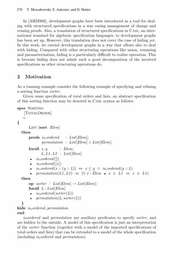
In [AHMS00], development graphs have been introduced as a tool for deal-ing with structured specifications in a way easing management of change andreusing proofs. Also, a translation of structured specifications in Casl, an inter-national standard for algebraic specification languages, to development graphshas been set up. However, this translation does not cover the case of hiding yet.In this work, we extend development graphs in a way that allows also to dealwith hiding. Compared with other structuring operations like union, renamingand parameterization, hiding is a particularly difficult to realize operation. Thisis because hiding does not admit such a good decomposition of the involvedspecifications as other structuring operations do.
2 Motivation
As a running example consider the following example of specifying and refininga sorting function sorter.
Given some specification of total orders and lists, an abstract specificationof this sorting function may be denoted in Casl syntax as follows:
spec Sorting
[TotalOrder]=
{List [sort Elem ]
then
preds is ordered : List [Elem];permutation : List [Elem] × List [Elem];
forall x , y : Elem;L,L1 ,L2 : List [Elem]
• is ordered([])• is ordered([x ])• is ordered(x :: (y :: L)) ⇔ x ≤ y ∧ is ordered(y :: L)• permutation(L1 ,L2 ) ⇔ (∀ x : Elem • x ∈ L1 ⇔ x ∈ L2 )
then
op sorter : List [Elem] → List [Elem];forall L : List [Elem]• is ordered(sorter(L))• permutation(L, sorter(L))
}hide is ordered , permutationend
is ordered and permutation are auxiliary predicates to specify sorter, andare hidden to the outside. A model of this specification is just an interpretationof the sorter function (together with a model of the imported specifications oftotal orders and lists) that can be extended to a model of the whole specification(including is ordered and permutation).
270 T. Mossakowski, S. Autexier, and D. Hutter
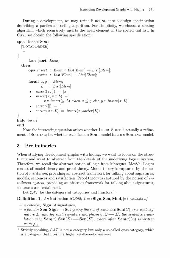
During a development, we may refine Sorting into a design specificationdescribing a particular sorting algorithm. For simplicity, we choose a sortingalgorithm which recursively inserts the head element in the sorted tail list. InCasl we obtain the following specification:
spec InsertSort
[TotalOrder]=
{List [sort Elem ]
thenops insert : Elem × List [Elem] → List [Elem];
sorter : List [Elem] → List [Elem];
forall x , y : Elem;L : List [Elem]
• insert(x , []) = [x ]• insert(x , y :: L) =
x :: insert(y ,L) when x ≤ y else y :: insert(x ,L)
• sorter([]) = []• sorter(x :: L) = insert(x , sorter(L))
}hide insertend
Now the interesting question arises whether InsertSort is actually a refine-ment of Sorting; i.e. whether each InsertSort-model is also a Sorting-model.
3 Preliminaries
When studying development graphs with hiding, we want to focus on the struc-turing and want to abstract from the details of the underlying logical system.Therefore, we recall the abstract notion of logic from Meseguer [Mes89]. Logicsconsist of model theory and proof theory. Model theory is captured by the no-tion of institution, providing an abstract framework for talking about signatures,models, sentences and satisfaction. Proof theory is captured by the notion of en-tailment system, providing an abstract framework for talking about signatures,sentences and entailment.
Let CAT be the category of categories and functors.1
Definition 1. An institution [GB92] I = (Sign,Sen,Mod, |=) consists of
– a category Sign of signatures,– a functor Sen: Sign−→Set giving the set of sentences Sen(Σ) over each sig-
nature Σ, and for each signature morphism σ:Σ−→Σ′, the sentence trans-lation map Sen(σ): Sen(Σ)−→Sen(Σ′), where often Sen(σ)(ϕ) is writtenas σ(ϕ),
1 Strictly speaking, CAT is not a category but only a so-called quasicategory, whichis a category that lives in a higher set-theoretic universe.
271Extending Development Graphs with Hiding
– a functor Mod: Signop−→CAT giving the category of models over a givensignature, and for each signature morphism σ:Σ−→Σ′, the reduct functorMod(σ): Mod(Σ′) −→ Mod(Σ), where often Mod(σ)(M′) is written asM ′|σ,
– a satisfaction relation |=Σ ⊆ |Mod(Σ)| × Sen(Σ) for each Σ ∈ Sign,
such that for each σ:Σ −→Σ′ in Sign M ′ |=Σ′ σ(ϕ) ⇔ M ′|σ |=Σ ϕ holds foreach M ′ ∈ Mod(Σ′) and ϕ ∈ Sen(Σ) (satisfaction condition).
Definition 2. An entailment system E = (Sign,Sen,`) consists of a categorySign of signatures, a functor Sen: Sign −→ Set giving the set of sentencesover a given signature, and for each Σ ∈ |Sign|, an entailment relation Σ⊆|Sen(Σ)| × Sen(Σ) such that the following properties are satisfied:
1. reflexivity: for any ϕ ∈ Sen(Σ), {ϕ} `Σ ϕ,2. monotonicity: if Γ `Σ ϕ and Γ ′ ⊇ Γ then Γ ′ `Σ ϕ,3. transitivity: if Γ `Σ ϕi, for i ∈ I, and Γ ∪ {ϕi | i ∈ I} `Σ ψ, then Γ `Σ ψ,4. `-translation: if Γ `Σ ϕ, then for any σ:Σ−→Σ′ in Sign, σ[Γ ] `Σ′ σ(ϕ).
We write Γ`Σ for {ϕ |Γ `Σ ϕ}.
Definition 3. A logic is a 5-tuple LOG = (Sign,Sen,Mod,`, |=) such that:
1. (Sign,Sen,`) is an entailment system (denoted by ent(LOG)),2. (Sign,Sen,Mod, |=) is an institution (denoted by inst(LOG)), and3. the following soundness condition is satisfied: for any Σ ∈ |Sign|, Γ ⊆
Sen(Σ) and ϕ ∈ Sen(Σ), Γ `Σ ϕ implies Γ |=Σ ϕ
A logic is complete if, in addition, Γ |=Σ ϕ implies Γ `Σ ϕ.
Throughout the rest of the paper, we will work with an arbitrary but fixedlogic LOG = (Sign,Sen,Mod,`, |=) such that Sign has finite colimits, andLOG admits weak amalgamation, i.e. Mod maps finite colimits to weak limits.
Given a diagram D: I−→Sign, let us call a family (mi)i∈|I| consistent withI , if for each i ∈ |I |, mi ∈ Mod(D(i)), and for each l: i−→j ∈ I , mj |D(l) = mi.
The weak amalgamation property can now be reformulated as follows: LOGadmits weak amalgamation iff for each diagram D: I −→Sign and each family(mi)i∈|I| consistent with I , there exists a model m ∈ Colim D with m|µi = mi,where µi:D(i)−→Colim D are the colimit injections.
There are plenty of logics satisfying the above requirements, e.g. many-sortedequational logic, many-sorted first-order logic, various temporal and object-oriented logics etc. The logic underlying Casl, subsorted partial first-order logicwith sort generation constraints, does not admit weak amalgamation. However,the Casl logic can be embedded into a logic with a richer signature categoryand a model functor admitting (weak) amalgamation [SMHKT01]. Hence, theresults of this paper also are applicable for CASL, if colimits are taken in thericher signature category.
272 T. Mossakowski, S. Autexier, and D. Hutter
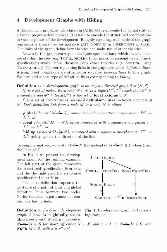
4 Development Graphs with Hiding
A development graph, as introduced in [AHMS00], represents the actual state ofa formal program development. It is used to encode the structured specificationsin various phases of the development. Roughly speaking, each node of the graphrepresents a theory like for instance List, Sorting or InsertSort in Casl.The links of the graph define how theories can make use of other theories.
Leaves in the graph correspond to basic specifications, which do not makeuse of other theories (e.g. Total order). Inner nodes correspond to structuredspecifications which define theories using other theories (e.g. Sorting usingTotal order). The corresponding links in the graph are called definition links.Arising proof obligations are attached as so-called theorem links to this graph.We here add a new type of definition links corresponding to hiding.
Definition 4. A development graph is an acyclic, directed graph S = 〈N ,L〉.N is a set of nodes. Each node N ∈ N is a tuple (ΣN , ΦN ) such that ΣN is
a signature and ΦN ⊆ Sen(ΣN ) is the set of local axioms of N .L is a set of directed links, so-called definition links, between elements of
N . Each definition link from a node M to a node N is either
– global (denoted M σ N), annotated with a signature morphism σ : ΣM →ΣN , or
– local (denoted M σ N), again annotated with a signature morphism σ :ΣM → ΣN , or
– hiding (denoted M σhN), annotated with a signature morphism σ : ΣN →
ΣM going against the direction of the link.
To simplify matters, we write M σ N ∈ S instead of M σ N ∈ L when L arethe links of S.
List+Order
Perm+OrderDef InsertSortDef
SorterProps
Sorting InsertSort
c
h
h
id
Fig. 1. Development graph for the sort-ing example
In Fig. 1 we present the develop-ment graph for the running example:The left part of the graph representsthe structured specification Sorting,and the the right part the structuredspecification InsertSort.
The next definition captures theexistence of a path of local and globaldefinition links between two nodes.Notice that such a path must not con-tain any hiding links.
Definition 5. Let S be a developmentgraph. A node M is globally reach-able from a node N via a mapping σ,N σ M ∈ S for short, iff either N = M and σ = λ, or N σ′
K ∈ S, andK σ′′
M ∈ S, with σ = σ′′ ◦ σ′.
273Extending Development Graphs with Hiding
A node M is locally reachable from a node N via a mapping σ, N σ M ∈S for short, iff N σ M ∈ S or there is a nodeK with N σ′
K ∈ S, K σ′′M ∈
S, such that σ = σ′′ ◦ σ′.
Obviously global reachability implies local reachability since the theory of anode is defined with the help of local axioms.
Definition 6. Let S = 〈N ,L〉 be a development graph. A node N ∈ N is flat-able iff for all nodes M ∈ N with incoming hiding definition links, it holds thatN is not reachable from M .
The models of flatable nodes does not depend on existing hiding links. Thuswe use the original approach of defining the theory of a node:
Definition 7. Let S = 〈N ,L〉 be a development graph. For N ∈ N , the theoryThS(N) of N wrt. a development graph S is defined by
ThS(N) =
[ΦN ∪
⋃K
σN∈S
σ(ThS(K)) ∪⋃
Kσ
N∈Sσ(ΦK)
]`ΣN
For flatable nodes N , ThS(N) captures N completely. However, this is notthe case for nodes that are not flatable. Therefore, we cannot define a proof-theoretic semantics of development graphs as in [AHMS00]. Rather, we have touse a model-theoretic semantics. In Sect. 5 we will show how this model-theoreticsemantics relates to the proof theoretic semantics given in [AHMS00].
Definition 8. Given a node N ∈ N , its associated class ModS(N) of models(or N -models for short) consists of those ΣN -models n for which
– n satisfies the local axioms ΦN ,– for each K σ N ∈ S, n|σ is a K-model,– for each K σ N ∈ S, n|σ satisfies the local axioms ΦK , and– for each K σ
hN ∈ S, n has a σ-expansion k (i.e. k|σ = n) that is a K-
model.
Complementary to definition links, which define the theories of related nodes,we introduce the notion of a theorem link with the help of which we are able topostulate relations between different theories. Theorem links are the central datastructure to represent proof obligations arising in formal developments. Againwe distinguish between local and global theorem links (denoted by N σ M andN σ M respectively). We also need theorem links N σ θM (where for someΣ, θ:Σ −→ΣN and σ:Σ −→ΣM) involving hiding. The semantics of theoremlinks is given by the next definition.
Definition 9. Let S be a development graph and N , M nodes in S.S implies a global theorem link N σ M (denoted S |= N σ M) iff for all
m ∈ ModS(M), m|σ ∈ ModS(N).S implies a local theorem link N σ M (denoted S ` N σ M) iff for all
m ∈ ModS(M), m|σ |= φ for all φ ∈ ΦN .S implies a hiding theorem link N σ θM (denoted S |= N σ θM) iff for
all m ∈ ModS(M), m|σ has a θ-expansion to some N -model.
274 T. Mossakowski, S. Autexier, and D. Hutter
E.g. consider the development graph of the running example (cf. Fig. 1): Thetheorem link from Sorting to InsertSort expresses the postulation that thelatter is a refinement of the former. Furthermore, common proof obligations in aformal development can be encoded into properties that specific global theoremlinks are implied by the actual development graph.
A global definition link M σ N in a development graph is a conservativeextension, if every M -model can be expanded along σ to an N -model. We willallow to annotate a global definition link as M σ
c N , which shall express thatit is a conservative extension. These annotations can be seen as another kind ofproof obligations.
5 Rules for Development Graphs with Hiding
The rules for theorem proving in development graphs given in [AHMS00] allowto decompose a global theorem link into local theorem links. Unfortunately, it isnot possible to decompose global theorem links starting from nodes with hidingdefinition links going (directly or indirectly) into them. This is because hiding issome kind of existential quantification, and in general it is not possible to decom-pose an existential quantification of a conjunction into existential quantificationsof the conjuncts.
We therefore have to extend the set of rules from [AHMS00] to deal withhiding. We have two kinds of rules:
1. Rules for hiding and conservative extension. These rules are suited to pushtheorem links along the hidings inside the development graph, such that theyeventually can be decomposed into local theorem links.
2. Decomposition rules from [AHMS00]. They allow to split global theoremlinks into local and hiding theorem links.
5.1 Rules for Hiding and Conservative Extension
We now come to the rules for hiding and conservative extension. We introducetwo rules to shift theorem links over hiding, one dealing with hiding links on theleft hand side of a theorem link, and the other one with hiding links on the righthand side of a theorem link.
Since the first rule is quite powerful, we need some preliminary notions.Given a node N in a development graph S = 〈N ,L〉, the idea is that we unfoldthe subgraph below N into a tree and form a diagram with this tree. Moreformally, define the diagram D: I −→ Sign associated with N together with amap G: |I |−→N inductively as follows:
– 〈N〉 is an object in I , with D(〈N〉) = NΣ. Let G(〈N〉) be just N .
– if i = 〈 Ml1 . . . ln
N 〉 is an object in I with l1, . . . , ln non-local linksin L, and l = K σ M is a (global or local) definition link in L, then
j = 〈 K lM
l1 . . . lnN 〉
275Extending Development Graphs with Hiding
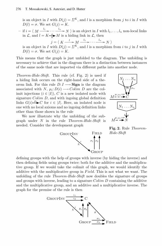
is an object in I with D(j) = ΣK , and l is a morphism from j to i in I withD(l) = σ. We set G(j) = K.
– if i = 〈 Ml1 . . . ln
N 〉 is an object in I with l1, . . . , ln non-local linksin L, and l = K σ
hM is a hiding link in L, then
j = 〈 K lM
l1 . . . lnN 〉
is an object in I with D(j) = ΣK , and l is a morphism from i to j in I withD(l) = σ. We set G(j) = K.
This means that the graph is just unfolded to the diagram. The unfolding isnecessary to achieve that in the diagram there is a distinction between instancesof the same node that are imported via different paths into another node.
N1 . . . Nn
N
M Cµ〈N〉◦σ
µ1 µn
N1 . . . Nn
M Nµ〈N〉◦σ
θh
Fig. 2. Rule Theorem-Hide-Shift
Theorem-Hide-Shift. This rule (cf. Fig. 2) is used ifa hiding link occurs on the right-hand side of a the-orem link. For this rule D: I −→ Sign is the diagramassociated with N , µi:D(i) −→ Colim D are the col-imit injections (i ∈ |I |), C is a new isolated node withsignature Colim D, and with ingoing global definitionlinks G(i)
µi C for i ∈ |I |. Here, an isolated node isone with no local axioms and no ingoing definition linksother than those shown in the rule
We now illustrate why the unfolding of the sub-graph under N in the rule Theorem-Hide-Shift isneeded. Consider the development graph
GroupInv Field
Group
ιh
σ1 σ2
defining groups with the help of groups with inverse (by hiding the inverse) andthen defining fields using groups twice: both for the additive and the multiplica-tive group. If we would take the colimit of this graph, we would identify theadditive with the multiplicative group in Field. This is not what we want. Theunfolding of the rule Theorem-Hide-Shift now doubles the signature of groupsand groups with inverse, leading to a signature Colim D containing the additiveand the multiplicative group, and an additive and a multiplicative inverse. Thegraph for the premise of the rule is then
GroupInv C
Group Field
ιh
ι1ι2
θ1 θ2
σ1
σ2
θ
276 T. Mossakowski, S. Autexier, and D. Hutter
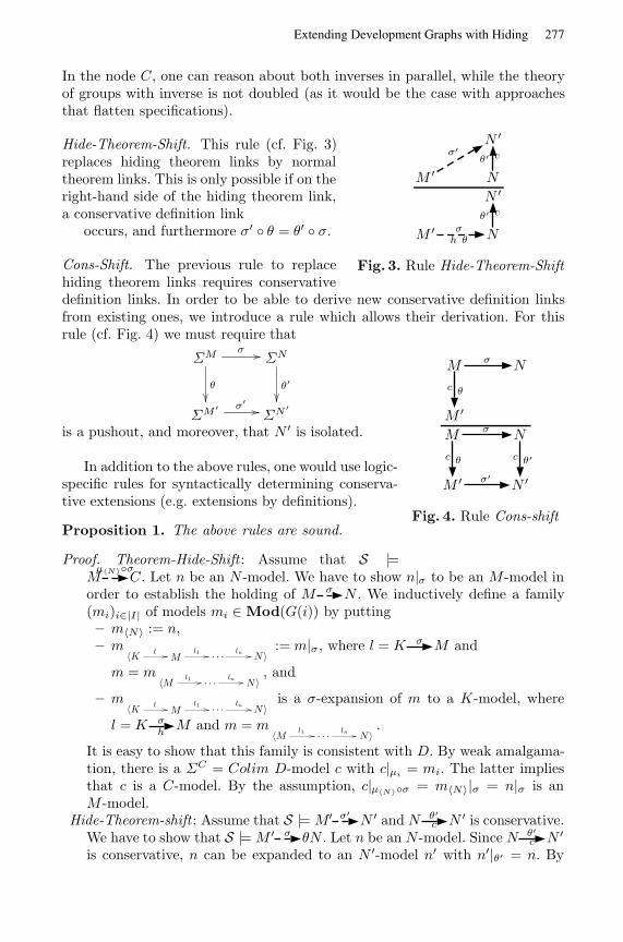
In the node C, one can reason about both inverses in parallel, while the theoryof groups with inverse is not doubled (as it would be the case with approachesthat flatten specifications).
N ′
M ′ N
σ′θ′ c
N ′
M ′ Nσ
h θ
θ′ c
Fig. 3. Rule Hide-Theorem-Shift
Hide-Theorem-Shift. This rule (cf. Fig. 3)replaces hiding theorem links by normaltheorem links. This is only possible if on theright-hand side of the hiding theorem link,a conservative definition link
occurs, and furthermore σ′ ◦ θ = θ′ ◦ σ.
Cons-Shift. The previous rule to replacehiding theorem links requires conservativedefinition links. In order to be able to derive new conservative definition linksfrom existing ones, we introduce a rule which allows their derivation. For thisrule (cf. Fig. 4) we must require that
M N
M ′
σ
θc
M N
M ′ N ′
σ
θc
σ′
θ′c
Fig. 4. Rule Cons-shift
ΣM
θ
σΣN
θ′
ΣM′ σ′ΣN ′
is a pushout, and moreover, that N ′ is isolated.
In addition to the above rules, one would use logic-specific rules for syntactically determining conserva-tive extensions (e.g. extensions by definitions).
Proposition 1. The above rules are sound.
Proof. Theorem-Hide-Shift : Assume that S |=Mµ〈N〉◦σ
C. Let n be an N -model. We have to show n|σ to be an M -model inorder to establish the holding of M σ N . We inductively define a family(mi)i∈|I| of models mi ∈ Mod(G(i)) by putting– m〈N〉 := n,– m
〈K lM
l1 . . . lnN〉
:= m|σ, where l = K σ M and
m = m〈M l1 . . . ln
N〉, and
– m〈K l
Ml1 . . . ln
N〉is a σ-expansion of m to a K-model, where
l = K σhM and m = m
〈M l1 . . . lnN〉
.
It is easy to show that this family is consistent with D. By weak amalgama-tion, there is a ΣC = Colim D-model c with c|µi = mi. The latter impliesthat c is a C-model. By the assumption, c|µ〈N〉◦σ = m〈N〉|σ = n|σ is anM -model.
Hide-Theorem-shift : Assume that S |= M′ σ′N ′ and N θ′
c N ′ is conservative.We have to show that S |= M ′ σ θN . Let n be an N -model. Since N θ′
c N ′
is conservative, n can be expanded to an N ′-model n′ with n′|θ′ = n. By
277Extending Development Graphs with Hiding

the assumption, n′|σ′ is an M ′-model. Thus, n′|σ′◦θ = n′|θ′◦σ = n|σ has aθ-expansion to an M ′-model.
Cons-shift : Assume that M θc M ′ is conservative. We have to prove that
N θ′c N ′ is conservative as well. Let n be an N -model. Since M θ M ′ is
conservative, n|σ has a θ-expansion m′ being an M ′-model. By weak amal-gamation, there is some ΣN ′
-model n′ with n′|σ′ = m′ and n′|θ′ = n. SinceN ′ is isolated, n′ is an N ′-model.
5.2 Rules for Decomposition
The rules for decomposition are taken from [AHMS00]. The ruleGlob-Decomposition has to be changed. It nowdecomposes a global theorem link from N to M into local theorem links into
M from those nodes from which N is reachable and into hiding theorem linksinto M from those nodes which are the source of a hiding link going into somenode from which N is reachable.
Moreover, we have added a subsumption rule, stating that global reachabilitysuffices to establish a global theorem link.
Glob-Decomposition:⋃K σ′
N{Kσ◦σ′M} ∪
⋃L
θh
K and K σ′N{Lσ◦σ′
θM}N σ M
Subsumption:N σ M
N σ M
Since the other rules have not changed, we just recall them here for sake ofcompleteness.
Loc-Decomposition I :
K σ L
K σ′′M
if L σ′M and σ′′(Φ(K)) = σ′(σ(Φ(K)))
Loc-Decomposition II :
N σ Mif N σ′
M and σ(Φ(N)) = σ′(Φ(N))
Basic Inference:ThS(M) ` σ(φ) for each φ ∈ ΦN
N σ M
Given a development graph containing some theorem links that have to beproved, the intention is that the above rules will be applied in a backwards man-ner as long as possible. The rules for hiding allow to shift the (global) theoremlinks to nodes without hiding involved, while the rules for decomposition allowto decompose the global theorem links into local ones. With Basic Inference,local theorem links can be proved using the entailment relation of the base logicLOG.
278 T. Mossakowski, S. Autexier, and D. Hutter
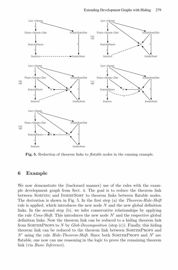
List+Order
Perm+Order+Def InsertSortDef
SorterProps
Sorting InsertSort
c
h
h
(a)⇒
List+Order
Perm+Order+Def InsertSortDef
SorterProps N
Sorting InsertSort
c
h
h
(b)⇒
List+Order
Perm+Order+Def InsertSortDef
SorterProps N’ N
Sorting InsertSort
c
h
hc
(c)⇒
List+Order
Perm+Order+Def InsertSortDef
SorterProps N’ N
Sorting InsertSort
c
h
hc
h
(d)⇒
List+Order
Perm+Order+Def InsertSortDef
SorterProps N’ N
Sorting InsertSort
c
h
hc
Fig. 5. Reduction of theorem links to flatable nodes in the running example.
6 Example
We now demonstrate the (backward manner) use of the rules with the exam-ple development graph from Sect. 4. The goal is to reduce the theorem linkbetween Sorting and InsertSort to theorem links between flatable nodes.The derivation is shown in Fig. 5. In the first step (a) the Theorem-Hide-Shiftrule is applied, which introduces the new node N and the new global definitionlinks. In the second step (b), we infer conservative relationships by applyingthe rule Cons-Shift. This introduces the new node N′ and the respective globaldefinition links. Now the theorem link can be reduced to a hiding theorem linkfrom SorterProps to N by Glob-Decomposition (step (c)). Finally, this hidingtheorem link can be reduced to the theorem link between SorterProps andN ′ using the rule Hide-Theorem-Shift. Since both SorterProps and N′ areflatable, one now can use reasoning in the logic to prove the remaining theoremlink (via Basic Inference).
279Extending Development Graphs with Hiding
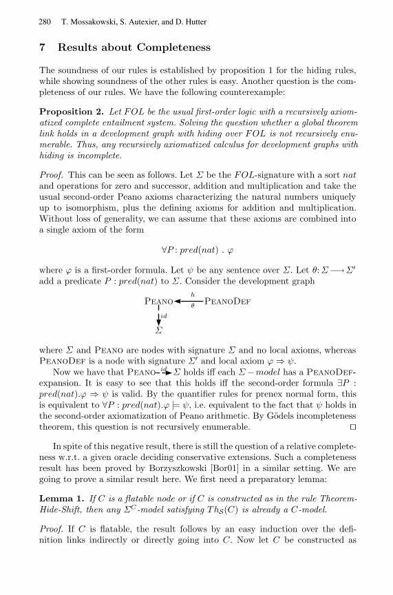
7 Results about Completeness
The soundness of our rules is established by proposition 1 for the hiding rules,while showing soundness of the other rules is easy. Another question is the com-pleteness of our rules. We have the following counterexample:
Proposition 2. Let FOL be the usual first-order logic with a recursively axiom-atized complete entailment system. Solving the question whether a global theoremlink holds in a development graph with hiding over FOL is not recursively enu-merable. Thus, any recursively axiomatized calculus for development graphs withhiding is incomplete.
Proof. This can be seen as follows. Let Σ be the FOL-signature with a sort natand operations for zero and successor, addition and multiplication and take theusual second-order Peano axioms characterizing the natural numbers uniquelyup to isomorphism, plus the defining axioms for addition and multiplication.Without loss of generality, we can assume that these axioms are combined intoa single axiom of the form
∀P : pred(nat) . ϕ
where ϕ is a first-order formula. Let ψ be any sentence over Σ. Let θ:Σ−→Σ′
add a predicate P : pred(nat) to Σ. Consider the development graph
Peano PeanoDef
Σ
θ
h
id
where Σ and Peano are nodes with signature Σ and no local axioms, whereasPeanoDef is a node with signature Σ′ and local axiom ϕ ⇒ ψ.
Now we have that Peanoid Σ holds iff each Σ−model has a PeanoDef-
expansion. It is easy to see that this holds iff the second-order formula ∃P :pred(nat).ϕ ⇒ ψ is valid. By the quantifier rules for prenex normal form, thisis equivalent to ∀P : pred(nat).ϕ |= ψ, i.e. equivalent to the fact that ψ holds inthe second-order axiomatization of Peano arithmetic. By Godels incompletenesstheorem, this question is not recursively enumerable. ut
In spite of this negative result, there is still the question of a relative complete-ness w.r.t. a given oracle deciding conservative extensions. Such a completenessresult has been proved by Borzyszkowski [Bor01] in a similar setting. We aregoing to prove a similar result here. We first need a preparatory lemma:
Lemma 1. If C is a flatable node or if C is constructed as in the rule Theorem-Hide-Shift, then any ΣC-model satisfying ThS(C) is already a C-model.
Proof. If C is flatable, the result follows by an easy induction over the defi-nition links indirectly or directly going into C. Now let C be constructed as
280 T. Mossakowski, S. Autexier, and D. Hutter
in the rule Theorem-Hide-Shift. We use the notation introduced in connectionwith the construction of C. For i ∈ |I |, let len(i) be the length of the pathi, and let p be the maximum of all len(i), i ∈ |I |. We prove by inductionover p − len(i) that for all i ∈ |I |, c|µi is a G(i)-model. Since C contains no
local axioms, the result then follows. Let i = 〈Ml1 . . . ln
N 〉 ∈ |I |.By induction hypothesis, for each ingoing link K l M , c|µj is a K-model for
j = 〈 K lM
l1 . . . lnN 〉. Now if l = K σ M , c|µi◦σ = c|µj , while
if l = K σhM , c|µj◦σ = c|µi . In the former case, c|µi reduces to a K-model,
while in the latter case, c|µi expands to a K-model. Hence in both cases, thelink l is satisfied by c|µi . Since c satisfies ThS(C) and N = G(i)
µi C, c|µi alsosatisfies the local axioms in M . Hence, c|µi is a model of M = G(i). ut
Theorem 1. Assume that the underlying logic LOG is complete. Then the rulesystem for development graphs with hiding is complete relative to an oracle forconservative extensions.
Proof. Assume S |= M σ N . We show that there is some faithful extension S1of S (i.e. new nodes and new definition links are added, but the latter go onlyinto new nodes) such that S1 `M σ N .
Let D: I −→Sign and C be as in the rule Theorem-Hide-Shift, and let c bea ΣC-model satisfying ThS(C). By Lemma 1, c is a C-model. Hence, c|µ〈N〉 isan N -model, and by the assumption S |= M σ N , c|µ〈N〉◦σ is an M -model. Wenow have for any K θ M :
1. c|µ〈N〉◦σ◦θ |= ΦK . By the satisfaction condition for institutions, we get c |=µ〈N〉(σ(θ(ΦK ))). By completeness of the underlying logic, we get ThS(C) `µ〈N〉(σ(θ(ΦK ))). By Basic Inference, S ` Kµ〈N〉◦σ◦θ
C.2. For L τ
hK, form the pushout
ΣK
τ
µ〈N〉◦σ◦θΣC
τ ′
ΣLµ′
Σ′
and obtain a new development graph S′ from S by introducing a new node L′
with signatureΣ′ and two ingoing definition links Lµ′
L′ and C τ ′L′. The
latter link is conservative: for any C-model c1, c1|µ〈N〉◦σ◦θ has a τ -expansionto an L-model c2, and by weak amalgamation, there is some Σ′-model c3with c3|τ ′ = c1 and c3|µ′ = c2, which is hence an L′-model. By the oraclefor conservativity, we get C τ ′
c L′. Now S′ ` L µ′L′ by Subsumption. By
Hide-Theorem-Shift, we get S′ ` Lµ〈N〉◦σ◦θτC.
Let S1 be the union of all the S′ constructed in step 2 above (assuming that allthe added nodes are distinct). By Glob-Decomposition, we get S1 `Mµ〈N〉◦σ
C. ByTheorem-Hide-Shift, we get S1 `M σ N . ut
281Extending Development Graphs with Hiding
Corollary 1. If LOG is complete, the decomposition rules are complete for prov-ing theorem links between flatable nodes.
Proof. By inspecting the proof of Theorem 1, one can see that for theorem linksbetween flatable nodes, case 2 is never entered, and thus neither the rules Cons-Shift and Hide-Theorem-Shift nor the oracle for conservativeness are needed.Since Lemma 1 also holds for flatable nodes, one can replace the node C in theproof of Theorem 1 with the node N , thus also avoiding the use of Theorem-Hide-Shift. ut
8 Conclusion and Related Work
We have extended the notion of development graph [AHMS00] to deal also withhiding. We have developed a semantics and a proof system for developmentgraphs with hiding. The proof system can easily shown to be sound.
Concerning completeness, with a counterexample, we show that there canbe no complete recursively axiomatized proof system for development graphswith hiding. However, we have shown our proof rules to be complete relative toa given oracle for detecting conservative extensions. We thus have achieved thesame degree of completeness as Borzyszkowski [Bor01] rule system for structuredspecifications. In one sense our system is more complete than Borzyszkowski’s:since our Theorem-Hide-Shift rule simulates something like Borzyszkowski’s nor-mal forms, we do not have to rely on the Craig interpolation property. For ex-ample, it is possible to solve a counterexample showing incompleteness in case offailure of interpolation in [Bor01] with our rules. Borzyszkowski refrains from do-ing normal form inference because with his way of computing normal forms, thestructure of the specification is lost. Note that this is not the case with our rules,since they just extend the structure of the development graph, while the axiomsare kept locally. One can even further optimize the rule Theorem-Hide-Shift byreducing the constructed diagram to those nodes that are really necessary, whichcan be achieved by taking the so-called final subcategory [AR94].
Compared with the rules in [Bor01], we have fewer but more complex rules.Our rules involve colimit computations that may be tedious for humans usingthe rules directly, but that are no problem for computer assisted proofs. Indeed,by exploiting the graph structure, development graphs with hiding can lead tomuch more efficient proofs than possible when using the usual proof rules forstructured specifications as in [Bor01].
Moreover, we expect no difficulty when extending the management of changedeveloped in [AHMS00] to the case of development graphs with hiding in orderto integrate the presented approach into the development graph system of INKA5.0 [AHMS99]. Then it will be possible to support the maintenance of changesin developments by machine also when hiding are present.
In [AHMS00], we have described a translation from CASL structured spec-ifications to development graphs. It should be straightforward to extend thistranslation to structured specifications with hiding.
282 T. Mossakowski, S. Autexier, and D. Hutter
References
[AHMS00] S. Autexier, D. Hutter, H. Mantel, and A. Schairer. Towards an evolu-tionary formal software-development using CASL. In C. Choppy, D. Bert,and P. Mosses, (Eds.), Recent Developments in Algebraic DevelopmentTechniques, 14th International Workshop, WADT’99, Bonas, France,LNCS 1827, page 73–88, Springer-Verlag, 2000.
[AHMS99] S. Autexier, D. Hutter, H. Mantel, A. Schairer. System Description: Inka5.0 - A Logic Voyager. In H. Ganzinger, (Ed.), Proceedings of CADE-16,Trento, Italy, LNAI 1632, Springer-Verlag, 1999.
[AR94] J. Adamek, J. Rosicky. Locally Presentable and Accessible Categories,Cambridge University Press, 1994.
[Bor01] T. Borzyszkowski. Logical systems for structured specifications. Theo-retical Computer Science. To appear.
[CASL98] CoFI Language Design Task Group. The Common Algebraic SpecificationLanguage (Casl) – Summary, Version 1.0 and additional Note S-9 onSemantics, available from http://www.brics.dk/Projects/CoFI, 1998.
[CM97] M. Cerioli, J. Meseguer. May I borrow your logic?, Theoretical ComputerScience, 173:311–347, 1997.
[DGS91] R. Diaconescu, J. Goguen, P. Stefaneas. Logical support for modulariza-tion, In G. Huet, G. Plotkin, (Eds), Workshop on Logical Frameworks,1991.
[GB92] J. A. Goguen and R. M. Burstall: Institutions: Abstract model theoryfor specification and programming, Journal of the Association for Com-puting Machinery, 39:95–146, 1992. Predecessor in: LNCS 164, 221–256,1984.
[HWB97] R. Hennicker, M. Wirsing, M. Bidoit. Proof systems for structured spec-ifications with observability operators, Theoretical Computer Science,173(2):393–443, 1997.
[HST94] R. Harper, D. Sannella, A. Tarlecki. Structured presentations and logicrepresentations, In Annals of Pure and Applied Logic, 67:113-160, 1994.
[Mes89] J. Meseguer. General logics, In Logic Colloquium 87, pages 275–329,North Holland, 1989.
[MKK97] T. Mossakowski, Kolyang, B. Krieg-Bruckner. Static semantic analysisand theorem proving for CASL, In 12th Workshop on Algebraic De-velopment Techniques, Tarquinia, LNCS 1376, pages 333–348, Springer-Verlag, 1998.
[ST88] D. Sannella, A. Tarlecki. Specifications in an arbitrary institution, In-formation and Computation, 76(2-3):165-210, 1988.
[ST92] D. Sannella, A. Tarlecki. Towards Formal Development of Programs fromAlgebraic Specifications: Model-Theoretic Foundations, 19th ICALP,Springer, LNCS 623, pages 656–671, Springer-Verlag, 1992.
[SMHKT01] L. Schroder, T. Mossakowski, P. Hoffman, B. Klin, and A. Tarlecki. Se-mantics for architectural specifications in CASL, In H. Hußmann, (Ed.),Proceedings of Fundamental Approaches to Software Engineering (FASE2001), Genova, Italy, 2001.
[VSE96] D. Hutter et. al. Verification Support Environment (VSE), Journal ofHigh Integrity Systems, Vol. 1, pages 523–530, 1996.
283Extending Development Graphs with Hiding
A Logic for the Java Modeling Language JML
Bart Jacobs and Erik Poll
Dept. Computer Science, Univ. Nijmegen,P.O. Box 9010, 6500 GL Nijmegen, The Netherlands.
{bart,erikpoll}@cs.kun.nl http://www.cs.kun.nl/∼{bart,erikpoll}
Abstract. This paper describes a specialised logic for proving speci-fications in the Java Modeling Language (JML). JML is an interfacespecification language for Java. It allows assertions like invariants, con-straints, pre- and post-conditions, and modifiable clauses as annotationsto Java classes, in a design-by-contract style. Within the LOOP projectat the University of Nijmegen JML is used for specification and verifi-cation of Java programs. A special compiler has been developed whichtranslates Java classes together with their JML annotations into logicaltheories for a theorem prover (PVS or Isabelle). The logic for JML thatwill be described here consists of tailor-made proof rules in the higherorder logic of the back-end theorem prover for verifying translated JMLspecifications. The rules efficiently combine partial and total correctness(like in Hoare logic) for all possible termination modes in Java, in a singlecorrectness formula.
1 Introduction
JML (for Java Modeling Language) [15,14] is a specification language tailoredto Java, primarily developed at Iowa State University. It allows assertions tobe included in Java code, specifying for instance pre- and postconditions andinvariants in the style of Eiffel and the design-by-contract approach [18]. JML hasbeen integrated with the specification language used for ESC/Java, the extendedstatic checker developed at Compaq System Research Center [17,27].
At Nijmegen, a formal denotational semantics has been developed for essen-tially all of sequential Java. A compiler has been built, the LOOP tool [5], whichtranslates a Java program into logical theories describing its semantics [13,4,10,9,12,8,26]. These logical theories are in a format that can serve as input for the-orem provers, which can then be used to prove properties of the Java program,thus achieving a high level of reliability for this program. The LOOP tool sup-ports output for the theorem provers PVS [20] and Isabelle [21]. This approachto verification of Java has demonstrated its usefulness for instance with the proofof a non-trivial invariant for the Vector class in the standard Java API [11]. Thecurrent main application area is JavaCard [1], see [24,25]. The LOOP tool isbeing extended to JML, so that it can be used to verify JML-annotated Javasource code. At the moment this works for a kernel of JML.
H. Hussmann (Ed.): FASE 2001, LNCS 2029, pp. 284–299, 2001.c© Springer-Verlag Berlin Heidelberg 2001
A Logic for the Java Modeling Language JML 285
One advantage of using a formal specification language is that tool supportbecomes possible. Work on tool support for JML focuses on the generation of run-time checks on preconditions for testing, at Iowa State University [6] extendedstatic checking, at Compaq System Research Center, and verification using theLOOP tool, at the University of Nijmegen. This offers a wide range of validationoptions—a key advantage of JML.
This paper presents a logic for reasoning about (sequential) Java programswhich is the result of several years of experience in this area. The semantical andlogical approach to Java within the LOOP project is bottom-up: it starts froman (automatic) translation of Java programs into what is ultimately a series oflow level get- and put-operations on a suitable memory model [4]. From thispoint onwards, several steps have been taken up the abstraction ladder.
1. At first, the results to be proved (about the Java program under consider-ation) were formulated in the higher order logic of the back-end theoremprover (PVS or Isabelle), and proved by fully unpacking their meaning interms of the low level (get and put) operations on the memory. Only rel-atively small programs can be handled like this, despite the usefulness ofautomatic rewriting.
2. Next a suitable Hoare logic for Java was introduced (in PVS and Isabelle) [10]for compositional reasoning about programs at a higher level of abstraction.This logic has different Hoare triples, corresponding to partial / total cor-rectness for each of the possible termination modes of Java statements andexpressions (normal / exception / return / break / continue). In theory thislogic is appropriate, but in practice it involves too many rules and leadsto too many duplications of proof obligations (for the different terminationmodes).
3. In a further abstraction step, the results to be proved were no longer for-mulated in PVS or Isabelle, but in a suitable specification language forJava, namely JML [14]. JML makes it possible to write specifications forJava programs without the need to know the details of these programs inPVS/Isabelle. Again, the translation from (a kernel of) JML to PVS/Isabelleis done automatically.
4. In a final step—the topic of this paper—a tailor-made logic is devel-oped for proving (in PVS/Isabelle) these JML specifications. This logic in-volves syntax-driven rules (in PVS/Isabelle), supported by appropriate proofstrategies, enabling the user to go step-by-step through a method body. Thelogic combines partial and total correctness together with the five differenttermination modes in a single correctness formula, resembling JML methodspecifications. This makes the logic both powerful and efficient in its use.Soundness of all these rules has been proved on the basis of the underly-ing semantics for Java. Most of the proofs are easy and just involve manycase distinctions. The soundness of the while rule, see Subsection 5.6, isnon-trivial.
The rules we describe below only handle the standard, imperative part of(sequential) Java, and not its typically object-oriented features (dealing for ex-
286 B. Jacobs and E. Poll
ample with dynamic binding), as in [22,19]. We do not need these rules becausewe can always fall back on our low level semantics where these issues are han-dled automatically [9]. This is a crucial point. Our logic for JML is not useddirectly at the Java source code level—as is standard in Hoare logics, see [3,16,7,22]—but at the translated Java code in the back-end theorem prover, i.e. onthe semantical level. But since the translation performed by the LOOP tool iscompositional, there is not much difference: during proofs in the logic for JMLone still follows the original code structurally. In a forward approach (followingthe execution order) one typically peels off the leading statements step-by-step,adapting the precondition in a suitable way. In every step one has to prove thisadaptation of the precondition, as a result of the leading statement. In our ap-proach the latter is typically done without the logic for JML, by going downto the lowest semantical level (as in 1 above), making efficient use of automaticrewriting. As mentioned, this works well for small programs. Note that an im-portant consequence of working at the semantic level
This combination of high level proof rules and low level automatic rewritingon the basis of the underlying semantics forms the strength of our pragmaticapproach, where we only introduce logical rules when this really suits us, in orderto achieve a higher level of abstraction in proofs. A consequence of working atthe semantical level is that we cannot really define a notion of completeness forour higher level rules (like in [19]), because completeness can only be defined fora syntactic level w.r.t. some lower semantic level.
In this paper we shall only talk about proving JML specifications for cer-tain Java implementations. We shall not use this here, but in certain cases theseproofs may actually rely on other JML specifications, for example for methodswhich are native (implemented in some other language than Java), or which maybe overridden. In the latter case one cannot rely on a specific implementation,because it may be different in subclasses. In a behavioural approach to subtyp-ing [2] (see also [23]) one then assumes that all implementations in subclassessatisfy the specification in the class in which the method is first introduced. Thisspecification will form the basis for verifications.
In order to explain our logic for JML, the paper will have to introduce quitea few languages: Java and its JML annotations (Section 2), higher order logic(as used in PVS and Isabelle) and the representation of Java statements andexpressions therein (Section 3), the meaning of JML method specifications inlogic (Section 4), and finally the rules themselves. Necessarily we cannot describeall details, and are forced to concentrate on the essentials. The paper involvesan example specification in JML, verified in PVS using the logic for JML. It isthe same example as in [10]—this time not on abstraction level 2 but on level 4,as described above.
2 Class and Method Specifications in JML
This section gives a brief impression of JML, concentrating on method spec-ifications. For more information, see [15,14]. JML adds assertions to Java by
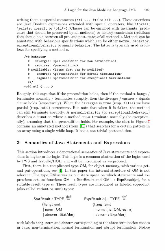
A Logic for the Java Modeling Language JML 287
writing them as special comments (/*@ ... @*/ or //@ ...). These assertionsare Java Boolean expressions extended with special operators, like \forall,\exists, \result or \old(-). Classes can be enriched with invariants (predi-cates that should be preserved by all methods) or history constraints (relationsthat should hold between all pre- and post-states of all methods). Methods can beannotated with behaviour specifications which can be either normal behavior,exceptional behavior or simply behavior. The latter is typically used as fol-lows for specifying a method m.
/*@ behavior@ diverges: <pre-condition for non-termination>@ requires: <precondition>@ modifiable: <items that can be modified>@ ensures: <postcondition for normal termination>@ signals: <postcondition for exceptional termination>@*/
void m() { ... }
Roughly, this says that if the precondition holds, then if the method m hangs /terminates normally / terminates abruptly, then the diverges / ensures / signalsclause holds (respectively). When the diverges is true (resp. false) we havepartial (resp. total) correctness. But note that when it is false, the methodcan still terminate abruptly. A normal behavior (or exceptional behavior)describes a situation where a method must terminate normally (or exception-ally), assuming that the precondition holds. For example, the class in Figure 1contains an annotated method (from [10]) that searches for a certain pattern inan array using a single while loop. It has a non-trivial postcondition.
3 Semantics of Java Statements and Expressions
This section introduces a denotational semantics of Java statements and expres-sions in higher order logic. This logic is a common abstraction of the logics usedby PVS and Isabelle/HOL, and will be introduced as we proceed.
First, there is a complicated type OM, for object memory, with various get-and put-operations, see [4]. In this paper the internal structure of OM is notrelevant. The type OM serves as our state space on which statements and ex-pressions act, as functions OM → StatResult and OM → ExprResult[α], for asuitable result type α. These result types are introduced as labeled coproduct(also called variant or sum) types:
StatResult : TYPE def={hang : unit| norm : OM| abnorm : StatAbn}
ExprResult[α] : TYPE def={hang : unit| norm : [ns : OM, res : α]| abnorm : ExprAbn}
with labels hang, norm and abnorm corresponding to the three termination modesin Java: non-termination, normal termination and abrupt termination. Notice
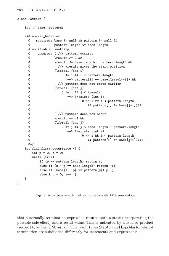
288 B. Jacobs and E. Poll
class Pattern {
int [] base, pattern;
/*@ normal_behavior@ requires: base != null && pattern != null &&@ pattern.length <= base.length;@ modifiable: \nothing;@ ensures: ( /// pattern occurs;@ \result >= 0 &&@ \result <= base.length - pattern.length &&@ /// \result gives the start position@ (\forall (int i)@ 0 <= i && i < pattern.length@ ==> pattern[i] == base[\result+i]) &&@ /// pattern does not occur earlier@ (\forall (int j)@ 0 <= j && j < \result@ ==> (\exists (int i)@ 0 <= i && i < pattern.length@ && pattern[i] != base[j+i])))@ ||@ ( /// pattern does not occur@ \result == -1 &&@ (\forall (int j)@ 0 <= j && j < base.length - pattern.length@ ==> (\exists (int i)@ 0 <= i && i < pattern.length@ && pattern[i] != base[j+i])));@*/
int find_first_occurrence () {int p = 0, s = 0;while (true)
if (p == pattern.length) return s;else if (s + p == base.length) return -1;else if (base[s + p] == pattern[p]) p++;else { p = 0; s++; }
}}
Fig. 1. A pattern search method in Java with JML annotation
that a normally termination expression returns both a state (incorporating thepossible side-effect) and a result value. This is indicated by a labeled product(record) type [ ns : OM, res : α ]. The result types StatAbn and ExprAbn for abrupttermination are subdivided differently for statements and expressions:
A Logic for the Java Modeling Language JML 289
StatAbn : TYPE def={ excp : [ es : OM, ex : RefType ]| rtrn : OM| break : [ bs : OM, blab : lift[string] ]| cont : [ cs : OM, clab : lift[string] ] }
ExprAbn : TYPE def=[ es : OM, ex : RefType ]
The type RefType is used for references, containing either the null-reference or apointer to a memory location. It describes the reference to an exception object,in case an exception is thrown. The lift type constructor adds a bottom elementbot to an arbitrary type, and keeps all original elements a as up a. It is usedbecause break and continue statements in Java can be used both with andwithout label (represented as string).
On the basis of this representation of statements and expressions all languageconstructs from (sequential) Java are formalised in type theory (and used in thetranslation performed by the LOOP tool). For instance, the composition of twostatements s, t : OM → StatResult is defined as:
(s ; t) def= λx : OM. CASES s · x OF { hang 7→ hang| norm y 7→ t · y
| abnorm a 7→ abnorm a }
where · is used for function application, and CASES for pattern matching on thelabels of the StatResult coproduct type. What is important to note is that if thestatement s hangs or terminates abruptly, then so does the composition s ; t.
There is no space to describe all these constructs in detail. We mention someof them that will be used later. Sometimes we need to execute an expressiononly for its side-effect (if any). This is done via the function E2S, defined as:
E2S · e : OM → StatResult def=λx : OM. CASES e · x OF {
hang 7→ hang| norm y 7→ norm(y.ns)| abnorm a 7→ abnorm(excp(es = a.es, ex = a.ex)) }
for e : OM → ExprResult[α]. The notation y.ns describes field selection associatedwith y in the labeled product [ ns : OM, res : α ]. In the last line an expressionabnormality (an exception) is transformed into a statement abnormality. Java’sif-then-else becomes:
IF-THEN-ELSE · c · s · t : OM → StatResult def=λx : OM. CASES c · x OF {
hang 7→ hang| norm y 7→ IF y.resTHEN s · (y.ns)ELSE t · (y.ns)| abnorm a 7→ abnorm(excp(es = a.es, ex = a.ex)) }
290 B. Jacobs and E. Poll
for c : OM → ExprResult[bool] and s, t : OM → StatResult. The formalisation ofJava’s return statement (without argument) is:
RETURN : OM → StatResult def= λx : OM. abnorm(rtrnx)
This statement produces an abnormal “return” state. Such a return abnormalitycan be undone, via appropriate catch-return functions. In our translation of Javaprograms, such a function CATCH-RETURN is wrapped around every methodbody that returns void. First the method body is executed. This may resultin an abnormal state, because of a return. In that case the function CATCH-RETURN turns the state back to normal again. Otherwise, it leaves everythingunchanged.
CATCH-RETURN · s : OM → StatResult[OM] def=λx : OM. CASES s · x OF {
hang 7→ hang| norm y 7→ norm y
| abnorm a 7→ CASES a OF {excp e 7→ abnorm(excp e)
| rtrn z 7→ norm z
| break b 7→ abnorm(break b)| cont c 7→ abnorm(cont c) } }
The formalisation of creating and catching break and continue abnormalitiesworks similarly, via function CATCH-BREAK and CATCH-CONTINUE.
4 Semantics of Method Specifications
To start we define two labeled product types incorporating appropriately typedpredicates for the various termination modes of statements and expressions.
StatBehaviorSpec : TYPE def=[ diverges : OM → boolean,
requires : OM → boolean,
statement : OM → StatResult,ensures : OM → boolean,
signals : OM → RefType → boolean,
return : OM → boolean,
break : OM → lift[string] → boolean,
continue : OM → lift[string] → boolean ]
ExprBehaviorSpec[α] : TYPE def=[ diverges : OM → boolean,
requires : OM → boolean,
expression : OM→ExprResult[α],ensures : OM → α → boolean,
signals : OM → RefType→ boolean ]
Notice that the StatBehaviorSpec type has more entries than ExprBehaviorSpecprecisely because a statement in Java can terminate abruptly for more reasonsthan an expression.
A Logic for the Java Modeling Language JML 291
There are associated predicates which give the “obvious” meaning.
SB · sbs : boolean def=∀x ∈ OM. sbs.requires · x =⇒
CASES sbs.statement · x OF {hang 7→ sbs.diverges · x
| norm y 7→ sbs.ensures · y
| abnorm a 7→ CASES a OF {excp e 7→ sbs.signals · (e.es) · (e.ex)
| rtrn z 7→ sbs.return · z
| break b 7→ sbs.break · (b.bs) · (b.blab)| cont c 7→ sbs.continue · (c.cs) · (c.clab) } }
EB · ebs : boolean def=∀x ∈ OM. ebs.requires · x =⇒
CASES ebs.expression · x OF {hang 7→ ebs.diverges · x
| norm y 7→ ebs.ensures · (y.ns) · (y.res)| abnorm a 7→ ebs.signals · (a.es) · (a.ex) }
for sbs : StatBehaviorSpec and ebs : ExprBehaviorSpec[α]. Notice that the divergespredicate is evaluated in the pre-state, in case the statement/expression hangs,because in that case there is simply no post-state. All other predicates are eval-uated in the post-state.
The LOOP compiler translates JML method specifications into elements ofStatBehaviorSpec and ExprBehaviorSpec, depending on whether the method pro-duces a result or not. The additional entries in StatBehaviorSpec which do notoccur in JML specifications (the three last ones) are filled with default values.They may be filled with other values during proofs, typically because of catchingof abnormalities, see Subsection 5.4.
For example, consider a JML method specification
/*@ behavior@ diverges: d;@ requires: p;@ modifiable: mod;@ ensures: q;@ signals: (E e) r;@*/
void m() { ... }
292 B. Jacobs and E. Poll
in a class with invariant I. This specification gets translated (by the LOOPcompiler) into:
∀z : OM. SB · ( diverges = [[ d ]],requires = λx : OM. [[ I ]] · x ∧ [[ p ]] · x ∧ z = x,
statement = [[ m ]],ensures = λx : OM. [[ I ]] · x ∧ [[ q ]] · x · z ∧ z ≈mod x,
signals = λx : OM. λa : RefType. [[ I ]] · x ∧[[ a instanceof E ]] ∧[[ r ]] · x · z · a ∧ z ≈mod x,
return = λx : OM. false,break = λx : OM. λl : lift[string]. false,continue = λx : OM. λl : lift[string]. false )
The variable z is a logical variable which records the pre-state. It is neededbecause the normal and exceptional postconditions q and r may involve anoperator \old(e), requiring evaluation of e in the pre-state. The term z ≈mod xis an appropriate translation of the modifiable clause, expressing that x and zare almost the same, except for the fields that are mentioned in the modifiableclause1.
When translating a normal behavior the diverges and signals fields are set tothe constant predicate false; similarly, in an exceptional behavior the divergesand ensures fields become false.
5 Rules for Proving Method Specifications
This section discusses a representative selection of the inference rules that areused for verifying JML method specifications. Some of these rules are bureau-cratic, but most of them are “syntax driven”. In a goal-oriented view they shouldbe read up-side-down.
5.1 Diverges
Usually, the diverges clause in JML is constant, i.e. either true or false. Someof the rules below—for example, the composition rule in Figure 3—actuallyrequire it to be constant. This can always be enforced via the following rule—atthe expense of duplication of the number of proof obligations, see Figure 2.
We illustrate the soundness of this rule. We assume therefore that the as-sumptions above the line hold. In order to prove the conclusion, we have todistinguish three main cases, for an arbitrary state x : OM, satisfying p · x:
– s · x hangs. According to the definition of SB, we have to prove d · x. But¬d · x, leads to false by the second assumption.
1 Often it is convenient to weaken the precondition to λx : OM. [[ I ]] · x ∧ [[ p ]] · x ∧z ≈mod x, to obtain a more symmetric correctness formula.
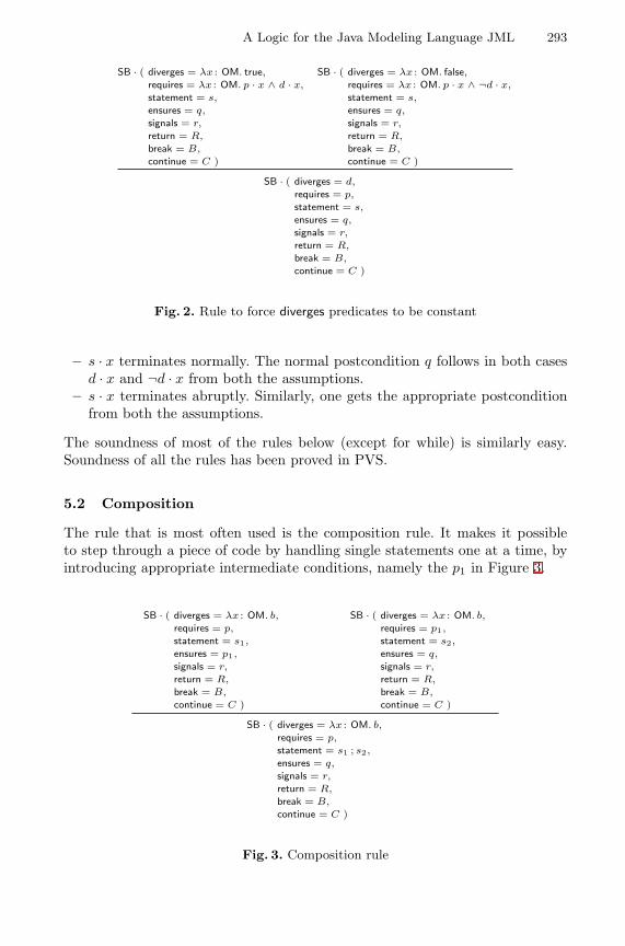
A Logic for the Java Modeling Language JML 293
SB · ( diverges = λx : OM. true,requires = λx : OM. p · x ∧ d · x,
statement = s,
ensures = q,
signals = r,
return = R,
break = B,
continue = C )
SB · ( diverges = λx : OM. false,requires = λx : OM. p · x ∧ ¬d · x,
statement = s,
ensures = q,
signals = r,
return = R,
break = B,
continue = C )
SB · ( diverges = d,
requires = p,
statement = s,
ensures = q,
signals = r,
return = R,
break = B,
continue = C )
Fig. 2. Rule to force diverges predicates to be constant
– s · x terminates normally. The normal postcondition q follows in both casesd · x and ¬d · x from both the assumptions.
– s · x terminates abruptly. Similarly, one gets the appropriate postconditionfrom both the assumptions.
The soundness of most of the rules below (except for while) is similarly easy.Soundness of all the rules has been proved in PVS.
5.2 Composition
The rule that is most often used is the composition rule. It makes it possibleto step through a piece of code by handling single statements one at a time, byintroducing appropriate intermediate conditions, namely the p1 in Figure 3.
SB · ( diverges = λx : OM. b,
requires = p,
statement = s1,
ensures = p1,
signals = r,
return = R,
break = B,
continue = C )
SB · ( diverges = λx : OM. b,
requires = p1,
statement = s2,
ensures = q,
signals = r,
return = R,
break = B,
continue = C )
SB · ( diverges = λx : OM. b,
requires = p,
statement = s1 ; s2,
ensures = q,
signals = r,
return = R,
break = B,
continue = C )
Fig. 3. Composition rule
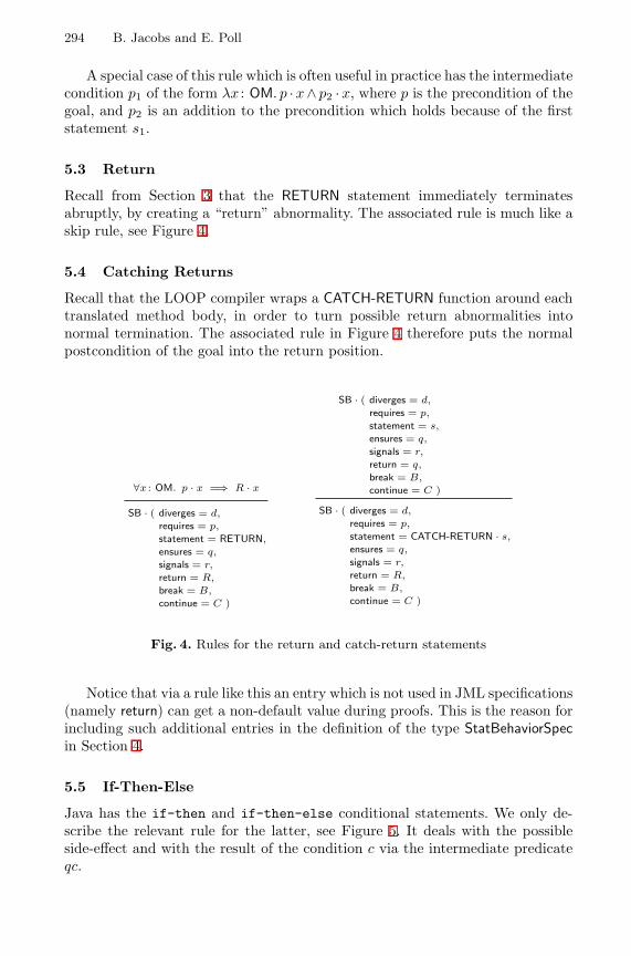
294 B. Jacobs and E. Poll
A special case of this rule which is often useful in practice has the intermediatecondition p1 of the form λx : OM. p · x ∧ p2 · x, where p is the precondition of thegoal, and p2 is an addition to the precondition which holds because of the firststatement s1.
5.3 Return
Recall from Section 3 that the RETURN statement immediately terminatesabruptly, by creating a “return” abnormality. The associated rule is much like askip rule, see Figure 4.
5.4 Catching Returns
Recall that the LOOP compiler wraps a CATCH-RETURN function around eachtranslated method body, in order to turn possible return abnormalities intonormal termination. The associated rule in Figure 4 therefore puts the normalpostcondition of the goal into the return position.
∀x : OM. p · x =⇒ R · x
SB · ( diverges = d,
requires = p,
statement = RETURN,
ensures = q,
signals = r,
return = R,
break = B,
continue = C )
SB · ( diverges = d,
requires = p,
statement = s,
ensures = q,
signals = r,
return = q,
break = B,
continue = C )
SB · ( diverges = d,
requires = p,
statement = CATCH-RETURN · s,
ensures = q,
signals = r,
return = R,
break = B,
continue = C )
Fig. 4. Rules for the return and catch-return statements
Notice that via a rule like this an entry which is not used in JML specifications(namely return) can get a non-default value during proofs. This is the reason forincluding such additional entries in the definition of the type StatBehaviorSpecin Section 4.
5.5 If-Then-Else
Java has the if-then and if-then-else conditional statements. We only de-scribe the relevant rule for the latter, see Figure 5. It deals with the possibleside-effect and with the result of the condition c via the intermediate predicateqc.
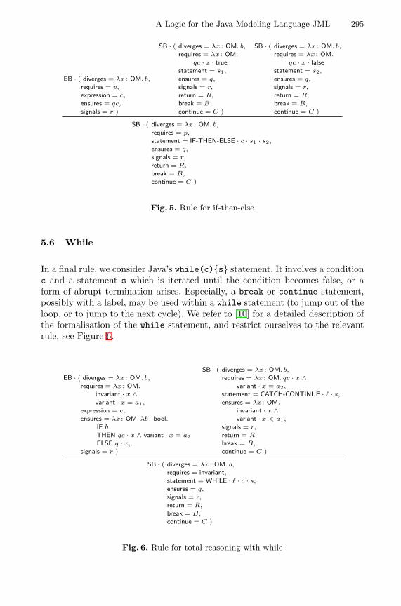
A Logic for the Java Modeling Language JML 295
EB · ( diverges = λx : OM. b,
requires = p,
expression = c,
ensures = qc,
signals = r )
SB · ( diverges = λx : OM. b,
requires = λx : OM.
qc · x · truestatement = s1,
ensures = q,
signals = r,
return = R,
break = B,
continue = C )
SB · ( diverges = λx : OM. b,
requires = λx : OM.
qc · x · falsestatement = s2,
ensures = q,
signals = r,
return = R,
break = B,
continue = C )
SB · ( diverges = λx : OM. b,
requires = p,
statement = IF-THEN-ELSE · c · s1 · s2,
ensures = q,
signals = r,
return = R,
break = B,
continue = C )
Fig. 5. Rule for if-then-else
5.6 While
In a final rule, we consider Java’s while(c){s} statement. It involves a conditionc and a statement s which is iterated until the condition becomes false, or aform of abrupt termination arises. Especially, a break or continue statement,possibly with a label, may be used within a while statement (to jump out of theloop, or to jump to the next cycle). We refer to [10] for a detailed description ofthe formalisation of the while statement, and restrict ourselves to the relevantrule, see Figure 6.
EB · ( diverges = λx : OM. b,
requires = λx : OM.
invariant · x ∧variant · x = a1,
expression = c,
ensures = λx : OM. λb : bool.IF b
THEN qc · x ∧ variant · x = a2
ELSE q · x,
signals = r )
SB · ( diverges = λx : OM. b,
requires = λx : OM. qc · x ∧variant · x = a2,
statement = CATCH-CONTINUE · ` · s,
ensures = λx : OM.
invariant · x ∧variant · x < a1,
signals = r,
return = R,
break = B,
continue = C )
SB · ( diverges = λx : OM. b,
requires = invariant,statement = WHILE · ` · c · s,
ensures = q,
signals = r,
return = R,
break = B,
continue = C )
Fig. 6. Rule for total reasoning with while
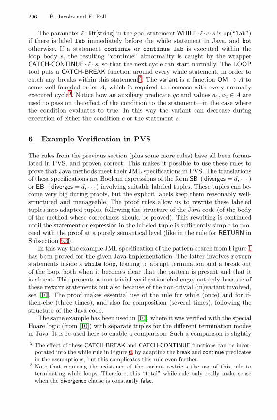
296 B. Jacobs and E. Poll
The parameter ` : lift[string] in the goal statement WHILE ·` ·c ·s is up(“lab”)if there is label lab immediately before the while statement in Java, and bototherwise. If a statement continue or continue lab is executed within theloop body s, the resulting “continue” abnormality is caught by the wrapperCATCH-CONTINUE · ` · s, so that the next cycle can start normally. The LOOPtool puts a CATCH-BREAK function around every while statement, in order tocatch any breaks within this statement2. The variant is a function OM → A tosome well-founded order A, which is required to decrease with every normallyexecuted cycle3. Notice how an auxiliary predicate qc and values a1, a2 ∈ A areused to pass on the effect of the condition to the statement—in the case wherethe condition evaluates to true. In this way the variant can decrease duringexecution of either the condition c or the statement s.
6 Example Verification in PVS
The rules from the previous section (plus some more rules) have all been formu-lated in PVS, and proven correct. This makes it possible to use these rules toprove that Java methods meet their JML specifications in PVS. The translationsof these specifications are Boolean expressions of the form SB ·( diverges = d, · · · )or EB · ( diverges = d, · · · ) involving suitable labeled tuples. These tuples can be-come very big during proofs, but the explicit labels keep them reasonably well-structured and manageable. The proof rules allow us to rewrite these labeledtuples into adapted tuples, following the structure of the Java code (of the bodyof the method whose correctness should be proved). This rewriting is continueduntil the statement or expression in the labeled tuple is sufficiently simple to pro-ceed with the proof at a purely semantical level (like in the rule for RETURN inSubsection 5.3).
In this way the example JML specification of the pattern-search from Figure 1has been proved for the given Java implementation. The latter involves returnstatements inside a while loop, leading to abrupt termination and a break outof the loop, both when it becomes clear that the pattern is present and that itis absent. This presents a non-trivial verification challenge, not only because ofthese return statements but also because of the non-trivial (in)variant involved,see [10]. The proof makes essential use of the rule for while (once) and for if-then-else (three times), and also for composition (several times), following thestructure of the Java code.
The same example has been used in [10], where it was verified with the specialHoare logic (from [10]) with separate triples for the different termination modesin Java. It is re-used here to enable a comparison. Such a comparison is slightly2 The effect of these CATCH-BREAK and CATCH-CONTINUE functions can be incor-
porated into the while rule in Figure 6, by adapting the break and continue predicatesin the assumptions, but this complicates this rule even further.
3 Note that requiring the existence of the variant restricts the use of this rule toterminating while loops. Therefore, this “total” while rule only really make sensewhen the divergence clause is constantly false.
A Logic for the Java Modeling Language JML 297
tricky because when the proof was re-done with the proof rules for JML, boththe variant and invariant were already known. Also, no time had to be spenton formulating the required correctness property in PVS, because this could allbe done (more conveniently) in JML. Taking this into account, the new rulesstill give a considerable speed-up of the proof. The verification is no longer amatter of days, but has become a matter of hours. The main reason is that thecorrectness formulas in the new logic for JML combine all termination modes ina single formula, and thus requires only one rule per language construct, withfewer assumptions.
7 Conclusion
In this paper JML method specification have been transformed into correctnessformulas in an associated logic. These formulas extend standard Hoare triples(and those from [10]) by combining all possible termination modes for Java, nat-urally following the (coalgebraic) representation of statements and expressions.The correctness formulas capture all essential ingredients for an axiomatic se-mantics for Java. In combination with the underlying low-level, memory-basedsemantics of Java, these rules for JML provide an efficient, powerful and flexiblesetting for tool-assisted verification of Java programs with JML annotations.
Acknowledgements. Thanks are due to Joachim van den Berg and MariekeHuisman for discussing various aspects of the rules for JML.
References
1. JavaCard API 2.1. http://java.sun.com/products/javacard/htmldoc/.2. P. America. Designing an object-oriented language with behavioural subtyping.
In J.W. de Bakker, W.P. de Roever, and G. Rozenberg, editors, Foundations ofObject-Oriented Languages, number 489 in Lect. Notes Comp. Sci., pages 60–90.Springer, Berlin, 1990.
3. K.R. Apt. Ten years of Hoare’s logic: A survey—part I. ACM Trans. on Progr.Lang. and Systems, 3(4):431–483, 1981.
4. J. van den Berg, M. Huisman, B. Jacobs, and E. Poll. A type-theoretic memorymodel for verification of sequential Java programs. In D. Bert, C. Choppy, andP. Mosses, editors, Recent Trends in Algebraic Development Techniques, number1827 in Lect. Notes Comp. Sci., pages 1–21. Springer, Berlin, 2000.
5. J. van den Berg and B. Jacobs. The LOOP compiler for Java and JML. Techn.Rep. CSI-R0019, Comput. Sci. Inst., Univ. of Nijmegen. To appear at TACAS’01.,2000.
6. A. Bhorkar. A run-time assertion checker for Java using JML. Techn. Rep. 00-08,Dep. of Comp. Science, Iowa State Univ.(http://www.cs.iastate.edu/∼leavens/JML.html), 2000.
7. F.S. de Boer. A WP-calculus for OO. In W. Thomas, editor, Foundations ofSoftware Science and Computation Structures, number 1578 in Lect. Notes Comp.Sci., pages 135–149. Springer, Berlin, 1999.
298 B. Jacobs and E. Poll
8. M. Huisman. Reasoning about JAVA Programs in higher order logic with PVS andIsabelle. PhD thesis, Univ. Nijmegen, 2001.
9. M. Huisman and B. Jacobs. Inheritance in higher order logic: Modeling and rea-soning. In M. Aagaard and J. Harrison, editors, Theorem Proving in Higher OrderLogics, number 1869 in Lect. Notes Comp. Sci., pages 301–319. Springer, Berlin,2000.
10. M. Huisman and B. Jacobs. Java program verification via a Hoare logic withabrupt termination. In T. Maibaum, editor, Fundamental Approaches to SoftwareEngineering, number 1783 in Lect. Notes Comp. Sci., pages 284–303. Springer,Berlin, 2000.
11. M. Huisman, B. Jacobs, and J. van den Berg. A case study in class library verifi-cation: Java’s Vector class. Techn. Rep. CSI-R0007, Comput. Sci. Inst., Univ. ofNijmegen. To appear in Software Tools for Technology Transfer, 2001.
12. B. Jacobs. A formalisation of Java’s exception mechanism. Techn. Rep. CSI-R0015,Comput. Sci. Inst., Univ. of Nijmegen. To appear at ESOP’01., 2000.
13. B. Jacobs, J. van den Berg, M. Huisman, M. van Berkum, U. Hensel, and H. Tews.Reasoning about classes in Java (preliminary report). In Object-Oriented Pro-gramming, Systems, Languages and Applications (OOPSLA), pages 329–340. ACMPress, 1998.
14. G.T. Leavens, A.L. Baker, and C. Ruby. JML: A notation for detailed design. InH. Kilov and B. Rumpe, editors, Behavioral Specifications of Business and Systems,pages 175–188. Kluwer, 1999.
15. G.T. Leavens, A.L. Baker, and C. Ruby. Preliminary design of JML: A behavioralinterface specification language for Java. Techn. Rep. 98-06, Dep. of Comp. Sci.,Iowa State Univ. (http://www.cs.iastate.edu/∼leavens/JML.html), 1999.
16. K.R.M. Leino. Toward Reliable Modular Programs. PhD thesis, California Inst. ofTechn., 1995.
17. K.R.M. Leino, J.B. Saxe, and R. Stata. Checking java programs via guarded com-mands. In B. Jacobs, G. T. Leavens, P. Muller, and A. Poetzsch-Heffter, editors,Formal Techniques for Java Programs. Proceedings of the ECOOP’99 Workshop.Techn. Rep. 251, Fernuniversitat Hagen, 1999. Also as Technical Note 1999-002,Compaq Systems Research Center, Palo Alto.
18. B. Meyer. Object-Oriented Software Construction. Prentice Hall, 2nd rev. edition,1997.
19. D. von Oheimb. Axiomatic semantics for Java`ight in Isabelle/HOL. TechnicalReport CSE 00-009, Oregon Graduate Inst., 2000. TPHOLS 2000 SupplementalProceedings.
20. S. Owre, S. Rajan, J.M. Rushby, N. Shankar, and M. Srivas. PVS: Combiningspecification, proof checking, and model checking. In R. Alur and T.A. Henzinger,editors, Computer Aided Verification, number 1102 in Lect. Notes Comp. Sci.,pages 411–414. Springer, Berlin, 1996.
21. L.C. Paulson. Isabelle: A Generic Theorem Prover. Number 828 in Lect. NotesComp. Sci. Springer, Berlin, 1994.
22. A. Poetzsch-Heffter and P. Muller. A programming logic for sequential Java. InS.D. Swierstra, editor, Programming Languages and Systems, number 1576 in Lect.Notes Comp. Sci., pages 162–176. Springer, Berlin, 1999.
23. E. Poll. A coalgebraic semantics of subtyping. In H. Reichel, editor, CoalgebraicMethods in Computer Science, number 33 in Elect. Notes in Theor. Comp. Sci.Elsevier, Amsterdam, 2000.

A Logic for the Java Modeling Language JML 299
24. E. Poll, J. van den Berg, and B. Jacobs. Specification of the JavaCard API in JML.In J. Domingo-Ferrer, D. Chan, and A. Watson, editors, Smart Card Research andAdvanced Application, pages 135–154. Kluwer Acad. Publ., 2000.
25. E. Poll, J. van den Berg, and B. Jacobs. Formal specification of the JavaCard APIin JML: the APDU class. Comp. Networks Mag., 2001. To appear.
26. Loop Project. http://www.cs.kun.nl/∼bart/LOOP/.27. Extended static checker ESC/Java. Compaq System Research Center.
http://www.research.digital.com/SRC/esc/Esc.html.
A Hoare Calculus for Verifying Java Realizationsof OCL-Constrained Design Models
Bernhard Reus1, Martin Wirsing2, and Rolf Hennicker2
1 School of Cognitive and Computing Sciences, University of Sussex at [email protected], Fax +44 1273 671 320
2 Institut fur Informatik, Ludwig-Maximilians-Universitat Munchen[hennicke|wirsing]@informatik.uni-muenchen.de
Abstract. The Object Constraint Language OCL offers a formal nota-tion for constraining the modelling elements occurring in UML diagrams.In this paper we apply OCL for developing Java realizations of UML de-sign models and introduce a new Hoare-Calculus for Java classes whichuses OCL as assertion language. The Hoare rules are as usual for whileprograms, blocks and (possibly recursive) method calls. Update of in-stance variables is handled by an explicit substitution operator whichalso takes care of aliasing. For verifying a Java subsystem w.r.t. a de-sign subsystem specified using OCL constraints we define an appropriaterealization relation and illustrate our approach by an example.
1 Introduction
Program verification is a dream which has not yet been realized in practicalsoftware development. With UML [17] the possibilities for achieving this dreamhave improved: UML allows one to express semantic constraints using OCLand offers notations such as the “realizes” relation for expressing correctnessrelationships between different diagrams on different levels of abstraction. Theobject constraint language OCL [23] offers a formal notation to constrain theinterpretation of modelling elements occurring in UML diagrams. OCL is sys-tematically used for rigorous software development in the Catalysis Approach[11]. The OCL notation is particularly suited to constrain class diagrams sinceOCL expressions allow one to navigate along associations and to describe con-ditions for object attributes in invariants and pre- and post-conditions of theoperations. The “realizes” relationship asserts that classes (written in a pro-gramming language) “realize” the requirements formulated in a more abstractclass diagram with constraints. It allows the programmer to express the cor-rectness of its implementations w.r.t. UML designs. However, to our knowledge,there is up to date no formal definition of the “realizes” relationship and also nopossibility of verification.
The aim of this paper is to close this gap. We propose a formalization ofthe “realizes” relationship w.r.t. Java implementations. For this purpose we firstdefine the syntactic and semantic requirements induced by a design model that
H. Hussmann (Ed.): FASE 2001, LNCS 2029, pp. 300–317, 2001.c© Springer-Verlag Berlin Heidelberg 2001
A Hoare Calculus for Verifying Java Realizations 301
is given by a UML class diagram and associated OCL constraints. The semanti-cal requirements are presented by Hoare formulas which express pre- and post-conditions for the method implementations. We verify these requirements usingthe axioms and rules of a new Hoare calculus for Java-like sequential programsproposed in [20]. Even if in practice such proofs will not be done in full ourapproach provides a tool for verifying the critical and important parts of a real-ization relationship.
Our work has been influenced by several other calculi. A Hoare calculusfor Java has been proposed by Poetzsch-Heffter and Muller [18,19]. We see asa main drawback that loc.cit. use an explicit representation of state in theircalculus which is thus not suited for OCL. Similarly the calculi of Abadi andLeino [1,15] do not fit to Java and OCL. Our calculus avoids this problem andis directly tuned to OCL. In this sense we follow rather the ideas of Gries andDe Boer who handle arrays and references by explicit substitution [10]. Otherrelevant work on Hoare-calculi includes a calculus of records [7] and treatmentof recursion [22].
The JML approach [14] extends the Java language such that programs (in-cluding exceptions) can be annotated by specifications. Proof obligations aregenerated but proofs can only be performed after a translation into a volumi-nous semantic description of Java that does not make use of a Hoare-logic butis of denotational flavour instead.
Our calculus extends the usual rules for while programs with blocks by rulesfor update of instance variables – handled by an explicit substitution operatorwhich also takes care of aliasing –, for creation of objects – using a specialconstant –, for recursive method specifications – taking care of inheritance –,and method calls.
2 The General Method
During the development of complex software systems various documents on dif-ferent levels of abstraction are produced ranging from analysis models to concreteimplementations (in terms of some programming language code). In this paperwe focus on the (formal) relationship between system design and implementa-tion.
2.1 The Design Model
Following the Unified Process (cf. [21]) a design model can be presented by adesign subsystem. We assume that the subsystem contains classes, inheritanceand association relations such that any association is directed and equipped witha role name and a multiplicity at the association end. As an essential ingredientof our approach the elements of a design model will be equipped with OCLconstraints for specifying properties like invariants of classes and pre- and post-conditions for the operations.
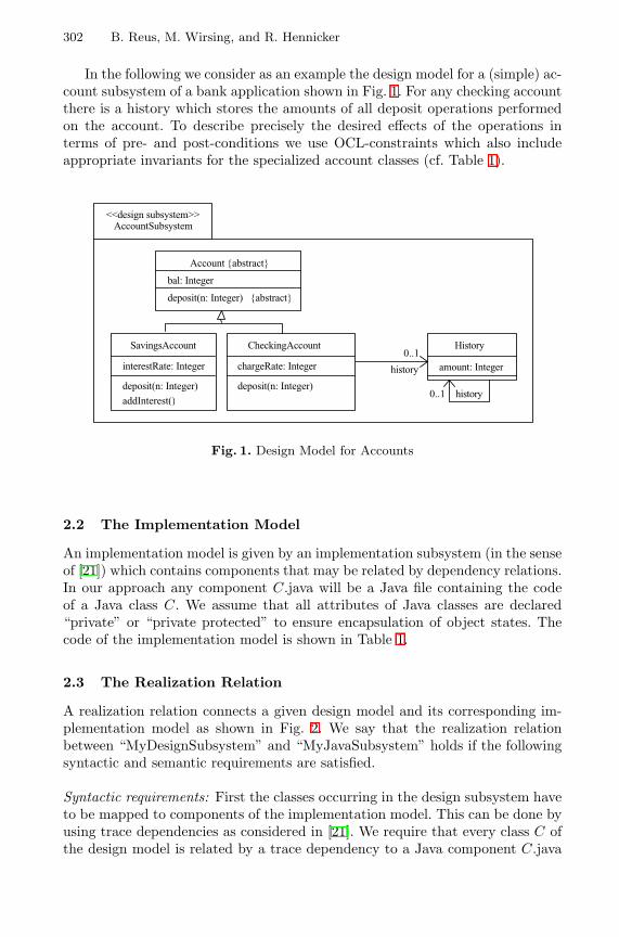
302 B. Reus, M. Wirsing, and R. Hennicker
In the following we consider as an example the design model for a (simple) ac-count subsystem of a bank application shown in Fig. 1. For any checking accountthere is a history which stores the amounts of all deposit operations performedon the account. To describe precisely the desired effects of the operations interms of pre- and post-conditions we use OCL-constraints which also includeappropriate invariants for the specialized account classes (cf. Table 1).
<<design subsystem>>
AccountSubsystem
0..1
history
History
amount: Integer
0..1 history
CheckingAccount
chargeRate: Integer
deposit(n: Integer)
Account {abstract}
bal: Integer
deposit(n: Integer) {abstract}
SavingsAccount
interestRate: Integer
deposit(n: Integer)
addInterest()
Fig. 1. Design Model for Accounts
2.2 The Implementation Model
An implementation model is given by an implementation subsystem (in the senseof [21]) which contains components that may be related by dependency relations.In our approach any component C.java will be a Java file containing the codeof a Java class C. We assume that all attributes of Java classes are declared“private” or “private protected” to ensure encapsulation of object states. Thecode of the implementation model is shown in Table 1.
2.3 The Realization Relation
A realization relation connects a given design model and its corresponding im-plementation model as shown in Fig. 2. We say that the realization relationbetween “MyDesignSubsystem” and “MyJavaSubsystem” holds if the followingsyntactic and semantic requirements are satisfied.
Syntactic requirements: First the classes occurring in the design subsystem haveto be mapped to components of the implementation model. This can be done byusing trace dependencies as considered in [21]. We require that every class C ofthe design model is related by a trace dependency to a Java component C.java
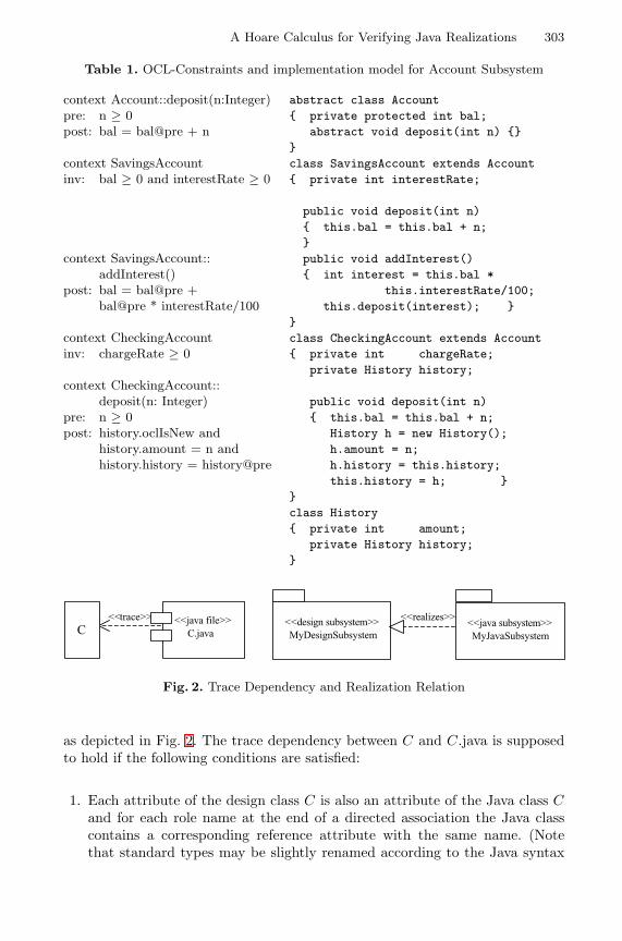
A Hoare Calculus for Verifying Java Realizations 303
Table 1. OCL-Constraints and implementation model for Account Subsystem
context Account::deposit(n:Integer)pre: n ≥ 0post: bal = bal@pre + n
context SavingsAccountinv: bal ≥ 0 and interestRate ≥ 0
context SavingsAccount::addInterest()
post: bal = bal@pre +bal@pre * interestRate/100
context CheckingAccountinv: chargeRate ≥ 0
context CheckingAccount::deposit(n: Integer)
pre: n ≥ 0post: history.oclIsNew and
history.amount = n andhistory.history = history@pre
abstract class Account{ private protected int bal;
abstract void deposit(int n) {}}class SavingsAccount extends Account{ private int interestRate;
public void deposit(int n){ this.bal = this.bal + n;}public void addInterest(){ int interest = this.bal *
this.interestRate/100;this.deposit(interest); }
}class CheckingAccount extends Account{ private int chargeRate;
private History history;
public void deposit(int n){ this.bal = this.bal + n;
History h = new History();h.amount = n;h.history = this.history;this.history = h; }
}class History{ private int amount;
private History history;}
<<trace>>
C<<java file>>
C.java
<<realizes>><<java subsystem>>
MyJavaSubsystem
<<design subsystem>>
MyDesignSubsystem
Fig. 2. Trace Dependency and Realization Relation
as depicted in Fig. 2. The trace dependency between C and C.java is supposedto hold if the following conditions are satisfied:
1. Each attribute of the design class C is also an attribute of the Java class Cand for each role name at the end of a directed association the Java classcontains a corresponding reference attribute with the same name. (Notethat standard types may be slightly renamed according to the Java syntax
304 B. Reus, M. Wirsing, and R. Hennicker
and that role names with multiplicity greater than one map to referenceattributes of some container type.)
2. For each operation m specified in the design class C there is a method dec-laration in the Java class C and vice versa (up to an obvious syntacticmodification of the signature). The operation m of the design model has theproperty { abstract } iff the method m is an abstract method.
3. The design class C is a (direct) subclass of a design class A iff the Java classC extends the Java class A.
These conditions guarantee (in particular) that the OCL expressions used asconstraints for the design model can be interpreted in the implementation modelwhich is necessary to define the semantical requirements. Moreover, note thatthe above conditions are satisfied by usual code generators for Java classes fromUML class diagrams.
Semantic requirements: Let us first stress that the semantic requirements con-sidered in the following are derived solely from the OCL constraints attachedto the design model. This means that constraints imposed by the UML classdiagram itself (like multiplicities or { query } properties of operations) and anykind of frame assumption will not be considered here if not explicitly expressedby an OCL constraint.
For the formulation of the semantic requirements we assume that the syn-tactic requirements from above are satisfied. Let us first discuss the role of in-variants. According to [23] an invariant INV-C defined in the context of a classC means that INV-C evaluates to true for all instances of C at any moment oftime. Since, by assumption, all attributes occurring in an implementation modelare private or private protected the state of an object can only be modified bymethod invocations. Therefore the basic idea is to require that the invariantis preserved by any method invocation1 for objects of C and that the invari-ant holds also for any object of C after its creation. These conditions, however,are not sufficient if there is a superclass A of C which has also an associatedinvariant, say INV-A. Then, in order to satisfy Liskov’s substitution principlefor subtypes [16], INV-A should be inherited by C. Hence, in general, we haveto consider for any class C the conjunction of INV-C and all invariants INV-Aassociated to a superclass A of C. For any design class C, this conjunction willbe denoted in the following by INV-conj-C. 2
For dealing with object creation we transform any post-condition POST oc-curring in the design model into the expression POST+ where any occurrenceof an OCL expression “t.oclIsNew” with some term t of some type C is replacedby “t.oclIsNew and INV-conj-C[t/this]”.
1 For simplicity, we assume that all methods are public. Otherwise the approach couldbe easily extended to take into account UML visibility markers in the design modelwhich then should be preserved by the trace dependency.
2 Obviously, if INV-C is stronger than INV-A for any superclass A then INV-conj-Cis equivalent to INV-C.
A Hoare Calculus for Verifying Java Realizations 305
Having the above definitions in mind we require that for each design class Cthe following conditions are satisfied:
1. Pre- and post-conditions associated to operations of C are respected bycorresponding method implementations. This means that for each operationm specified in the design class C with OCL-constraint
context C:: m(p1 : T1, . . . ,pn : Tn)pre : PRE post : POST
the given Java subsystem satisfies the Hoare formula
{PRE and INV-conj-C} C::m(p1 : T1, . . . , pn : Tn) {POST+}
where C denotes the Java class with method m defined in the componentC.java. The formal basis of this proof obligation will be provided in the nextsections. In particular, according to Definitions 5 and 6, the satisfaction ofthe above Hoare formula means that any method body of m provided in Cor in a subclass C ′ of C (which eventually overrides m) respects the givenpre- and post-condition. Thus Liskov’s substitution principle is satisfied.Note that it may also be the case that in the design model there is a subclassC ′ of the design class C which redefines m in the sense that it provides anadditional OCL constraint with pre- and post-conditions PRE ′ and POST ′
for m. In this case the realization relation requires that both Hoare formulas
{PRE and INV-conj-C} C::m(p1 : T1, . . . , pn : Tn) {POST+}{PRE ′ and INV-conj-C ′} C ′::m(p1 : T1, . . . , pn : Tn) {POST ′+}
must be satisfied by the Java subsystem. For instance, the pre- and post-conditions in our example lead to the proof obligations (1-3) of Table 2.
2. Invariants are preserved by method implementations. This means that foreach operation m specified in the design class C or in a superclass of C thegiven Java subsystem satisfies the Hoare formula
{PRE and INV-conj-C} C::m(p1 : T1, . . . , pn : Tn) {INV-conj-C}
where PRE denotes the pre-condition required for m (if any). For instance,considering the invariants of the account example we obtain the proof obli-gations (4-6) of Table 2.
3 OCLlight
OCLlight is a representative kernel of OCL which should be easily extendible tofull OCL. Yet, it deliberately differs from OCL in some minor syntactic pointsexplained below.
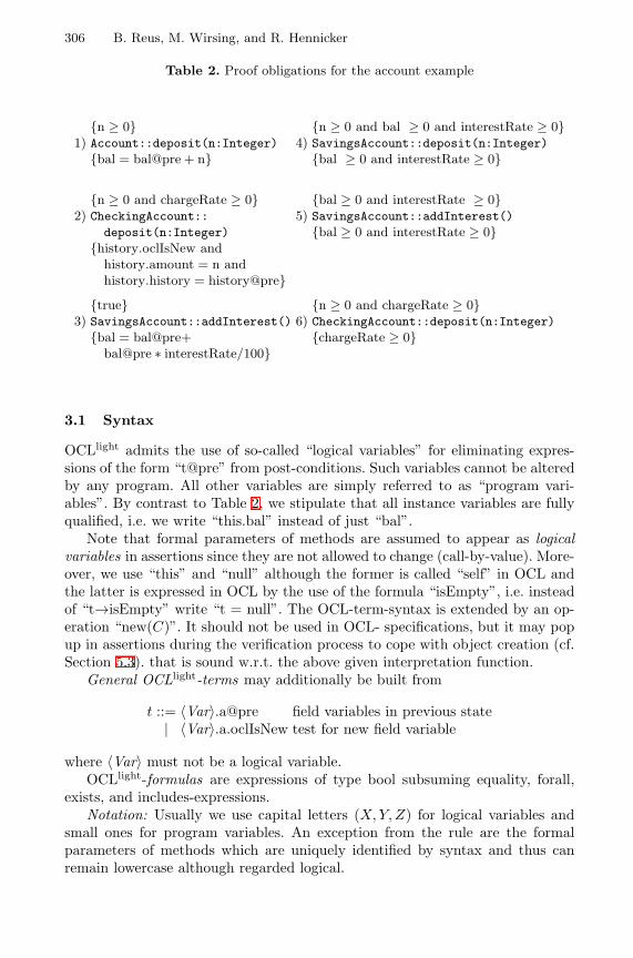
306 B. Reus, M. Wirsing, and R. Hennicker
Table 2. Proof obligations for the account example
{n ≥ 0} {n ≥ 0 and bal ≥ 0 and interestRate ≥ 0}1) Account::deposit(n:Integer) 4) SavingsAccount::deposit(n:Integer)
{bal = bal@pre + n} {bal ≥ 0 and interestRate ≥ 0}
{n ≥ 0 and chargeRate ≥ 0} {bal ≥ 0 and interestRate ≥ 0}2) CheckingAccount:: 5) SavingsAccount::addInterest()
deposit(n:Integer) {bal ≥ 0 and interestRate ≥ 0}{history.oclIsNew and
history.amount = n andhistory.history = history@pre}
{true} {n ≥ 0 and chargeRate ≥ 0}3) SavingsAccount::addInterest() 6) CheckingAccount::deposit(n:Integer)
{bal = bal@pre+ {chargeRate ≥ 0}bal@pre ∗ interestRate/100}
3.1 Syntax
OCLlight admits the use of so-called “logical variables” for eliminating expres-sions of the form “t@pre” from post-conditions. Such variables cannot be alteredby any program. All other variables are simply referred to as “program vari-ables”. By contrast to Table 2, we stipulate that all instance variables are fullyqualified, i.e. we write “this.bal” instead of just “bal”.
Note that formal parameters of methods are assumed to appear as logicalvariables in assertions since they are not allowed to change (call-by-value). More-over, we use “this” and “null” although the former is called “self” in OCL andthe latter is expressed in OCL by the use of the formula “isEmpty”, i.e. insteadof “t→isEmpty” write “t = null”. The OCL-term-syntax is extended by an op-eration “new(C)”. It should not be used in OCL- specifications, but it may popup in assertions during the verification process to cope with object creation (cf.Section 5.3). that is sound w.r.t. the above given interpretation function.
General OCLlight-terms may additionally be built from
t ::= 〈Var〉.a@pre field variables in previous state| 〈Var〉.a.oclIsNew test for new field variable
where 〈Var〉 must not be a logical variable.OCLlight-formulas are expressions of type bool subsuming equality, forall,
exists, and includes-expressions.Notation: Usually we use capital letters (X, Y, Z) for logical variables and
small ones for program variables. An exception from the rule are the formalparameters of methods which are uniquely identified by syntax and thus canremain lowercase although regarded logical.
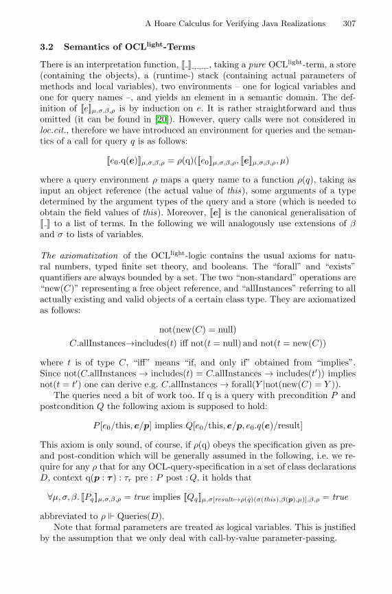
A Hoare Calculus for Verifying Java Realizations 307
3.2 Semantics of OCLlight-Terms
There is an interpretation function, [[ ]] , , , , taking a pure OCLlight-term, a store(containing the objects), a (runtime-) stack (containing actual parameters ofmethods and local variables), two environments – one for logical variables andone for query names –, and yields an element in a semantic domain. The def-inition of [[e]]µ,σ,β,ρ is by induction on e. It is rather straightforward and thusomitted (it can be found in [20]). However, query calls were not considered inloc.cit., therefore we have introduced an environment for queries and the seman-tics of a call for query q is as follows:
[[e0.q(e)]]µ,σ,β,ρ = ρ(q)([[e0]]µ,σ,β,ρ, [[e]]µ,σ,β,ρ, µ)
where a query environment ρ maps a query name to a function ρ(q), taking asinput an object reference (the actual value of this), some arguments of a typedetermined by the argument types of the query and a store (which is needed toobtain the field values of this). Moreover, [[e]] is the canonical generalisation of[[ ]] to a list of terms. In the following we will analogously use extensions of βand σ to lists of variables.
The axiomatization of the OCLlight-logic contains the usual axioms for natu-ral numbers, typed finite set theory, and booleans. The “forall” and “exists”quantifiers are always bounded by a set. The two “non-standard” operations are“new(C)” representing a free object reference, and “allInstances” referring to allactually existing and valid objects of a certain class type. They are axiomatizedas follows:
not(new(C) = null)C.allInstances→includes(t) iff not(t = null) and not(t = new(C))
where t is of type C, “iff” means “if, and only if” obtained from “implies”.Since not(C.allInstances → includes(t) = C.allInstances → includes(t′)) impliesnot(t = t′) one can derive e.g. C.allInstances → forall(Y |not(new(C) = Y )).
The queries need a bit of work too. If q is a query with precondition P andpostcondition Q the following axiom is supposed to hold:
P [e0/this, e/p] implies Q[e0/this, e/p, e0.q(e)/result]
This axiom is only sound, of course, if ρ(q) obeys the specification given as pre-and post-condition which will be generally assumed in the following, i.e. we re-quire for any ρ that for any OCL-query-specification in a set of class declarationsD, context q(p : τ ) : τr pre : P post :Q, it holds that
∀µ, σ, β. [[Pq]]µ,σ,β,ρ = true implies [[Qq]]µ,σ[result 7→ρ(q)(σ(this),β(p),µ)],β,ρ = true
abbreviated to ρ Queries(D).Note that formal parameters are treated as logical variables. This is justified
by the assumption that we only deal with call-by-value parameter-passing.
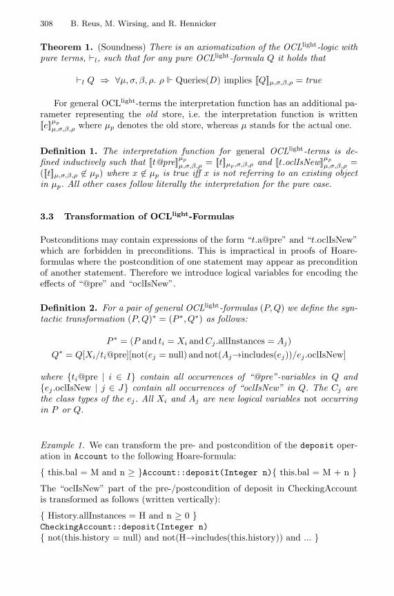
308 B. Reus, M. Wirsing, and R. Hennicker
Theorem 1. (Soundness) There is an axiomatization of the OCLlight-logic withpure terms, `l, such that for any pure OCLlight-formula Q it holds that
`l Q ⇒ ∀µ, σ, β, ρ. ρ Queries(D) implies [[Q]]µ,σ,β,ρ = true
For general OCLlight-terms the interpretation function has an additional pa-rameter representing the old store, i.e. the interpretation function is written[[e]]µp
µ,σ,β,ρ where µp denotes the old store, whereas µ stands for the actual one.
Definition 1. The interpretation function for general OCLlight-terms is de-fined inductively such that [[t@pre]]µp
µ,σ,β,ρ = [[t]]µp,σ,β,ρ and [[t.oclIsNew]]µp
µ,σ,β,ρ =([[t]]µ,σ,β,ρ 6∈ µp) where x 6∈ µp is true iff x is not referring to an existing objectin µp. All other cases follow literally the interpretation for the pure case.
3.3 Transformation of OCLlight-Formulas
Postconditions may contain expressions of the form “t.a@pre” and “t.oclIsNew”which are forbidden in preconditions. This is impractical in proofs of Hoare-formulas where the postcondition of one statement may appear as preconditionof another statement. Therefore we introduce logical variables for encoding theeffects of “@pre” and “oclIsNew”.
Definition 2. For a pair of general OCLlight-formulas (P, Q) we define the syn-tactic transformation (P, Q)∗ = (P ∗, Q∗) as follows:
P ∗ = (P and ti = Xi andCj .allInstances = Aj)Q∗ = Q[Xi/ti@pre][not(ej = null) and not(Aj→includes(ej))/ej .oclIsNew]
where {ti@pre | i ∈ I} contain all occurrences of “@pre”-variables in Q and{ej .oclIsNew | j ∈ J} contain all occurrences of “oclIsNew” in Q. The Cj arethe class types of the ej. All Xi and Aj are new logical variables not occurringin P or Q.
Example 1. We can transform the pre- and postcondition of the deposit oper-ation in Account to the following Hoare-formula:
{ this.bal = M and n ≥ }Account::deposit(Integer n){ this.bal = M + n }The “oclIsNew” part of the pre-/postcondition of deposit in CheckingAccountis transformed as follows (written vertically):
{ History.allInstances = H and n ≥ 0 }CheckingAccount::deposit(Integer n){ not(this.history = null) and not(H→includes(this.history)) and ... }
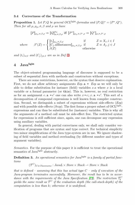
A Hoare Calculus for Verifying Java Realizations 309
3.4 Correctness of the Transformation
Proposition 1. Let P, Q be general OCLlight-formulas and (P, Q)∗ = (P ∗, Q∗).Then for all µ, µp, σ, β and ρ we have
[[P ]]µp,σ,β,ρ ⇒ [[Q]]µp
µ,σ,β,ρ iff [[P ∗]]µp,σ,β∗,ρ ⇒ [[Q∗]]µ,σ,β∗,ρ
where β∗(Z) =
[[ti]]µp,σ,β,ρ if Z ≡ Xi, i ∈ I[[Cj .allInstances]]µp,σ,β,ρ if Z ≡ Aj , j ∈ Jβ(Z) otherwise
and (ti)i∈I and (Cj)j∈J are as in Def. 2.
4 Javalight
The object-oriented programming language of discourse is supposed to be asubset of sequential Java with methods and constructors without exceptions.
There are some restrictions, however, on the syntax that deserve explanation.First, we do not allow arbitrary assignments Exp.a = Exp as we will only beable to define substitution for instance (field) variables x.a where x is a localvariable or a formal parameter (or this). This is, however, no real restrictionas for an assignment e.a = e′ one can also write x = e;x.a = e′. This sort of adecomposition of compound expressions is well known from compiler construc-tion. Second, we distinguish a subset of expressions without side-effects (Exp)and with possible side-effects (Sexp). The first forms a proper subset of OCLlight-expressions and can thus be substituted for (instance) variables. This is why allthe arguments of a method call must be side-effect free. The restricted syntaxfor expressions is still sufficient since, again, one can decompose any expressionusing auxiliary variables.
In general, dealing with partial correctness only, we shall only consider ver-ification of programs that are syntax and type correct. For technical simplicitytwo minor simplifications of the Java type-system are in use. We ignore shadow-ing of field variables and method overloading (by different number and types ofargument variables).
Semantics. For the purpose of this paper it is sufficient to treat the operationalsemantics of Javalight abstractly.
Definition 3. An operational semantics for Javalight is a family of partial func-tions
(T C)C∈Classname : JavaL × Store × Stack ⇀ Store × Stack
that is defined – assuming that this has actual type C – only if execution of theJava-program terminates successfully. Moreover, the result has to be in accor-dance with the requirements of the Java Specification [12]. The restriction T C
k
yields the same result as T C if the evaluation depth (the call-stack-depth) of thecomputation is less than k; otherwise it is undefined.
310 B. Reus, M. Wirsing, and R. Hennicker
This restriction is necessary to give a sound interpretation to specifications ofrecursive methods (see also [22,20]).
A possible operational semantics that fits can be found in [8,9,2]).
5 Hoare Calculus
In this section we present a Hoare calculus for Javalight with assertions writtenin pure OCLlight. This calculus extends the well-known Hoare calculi one canfind in any textbook (see e.g. [4] or the original text [13]) by a few rules coveringassignment to instance variables, object creation (see also [6,7]), method call,and method specification (inheritance).
5.1 Syntax
Because object-oriented programs are structured by means of classes which inturn break down to fields and methods, we introduce two different Hoare-likejudgements, where the one for methods is considered as a special abbreviation:
Definition 4. We first distinguish between two types of Hoare-triples, those forstatements {P} S {Q} and those for methods (also called method specifications){P} C :: m(p : τ ) {Q} where S is a Javalight-statement, C is a class type, P andQ are pure OCLlight formulas. For method specifications, all program variablesappearing in Q must be “this” or “result”. Recall that the formal parametersp are assumed to appear as logical variables since we assume a call-by-valueparameter mechanism. The judgments of the Hoare calculus are then as follows:
1. Derivable Statement TriplesΓ `C
D {P} S {Q} where Γ denotes a context being empty or consisting ofone method specification, D is the whole set of declarations, i.e. the completeJava-package of discourse, and C is the assumed class type of this (whichmay not be uniquely derivable from the statement S alone).
2. Derivable Method Triples`D {P} C :: m(p : τ ) {Q} where C and D are as above.
The context for Hoare triples is necessary for the treatment of recursive methodspecifications. For mutual recursive methods the context must be generalized tosets of method triples.
We omit the indices D and C if they can be derived from the context.
5.2 Semantics
The following definition of validity of triples holds for general OCLlight-assertionsP and Q.
Definition 5. Let T denote a semantic function for Javalight. Then Hoare-triples are said to hold relatively to evaluation depth smaller than k if the fol-lowing holds:
A Hoare Calculus for Verifying Java Realizations 311
1. Statement Triples (partial correctness of statements)|=D,C
k {P} S {Q}, if for any µ, σ, β we have
[[P ]]µ,σ,β,ρ = true ∧ T Ck (S, µ, σ) = (µ′, σ′) ⇒ [[Q]]µσ′,µ′,β,ρ = true
where ρ is defined as follows for any query of D defined in class Cq:
ρ(q)(o,a, µ) = (T Cq
k (body(Cq, q, D), µ, ∅[this 7→ o][p 7→ a])1(result)
2. Method Triples (partial correctness of methods)|=D
k {P} C::m(p : τ) {Q} if ∀C ′ ≤ C. |=D,C′k {P} body(C ′, m, D) {Q}
where body(C ′, m, D) is the body of m defined in class C ′ of program packageD. If C ′ just inherits m from some superclass C ′′ then body(C ′, m, D) =body(C ′′, m, D).
Note that it is not clear a priori that ρ Queries(D), but it will follow fromthe proof of `D {P} C::q( . . . ) {Q} for each query q with pre-condition P andpost-condition Q.
Definition 6. A triple T is valid in a context Γ , i.e. Γ |=D,C T , iff
∀k ∈ N. |=Dk Γ ⇒ |=D,C
k+1 T
5.3 Inductive Definition of the Hoare Calculus
In this section we present the rules (i.e. the calculus) for deriving correct speci-fications for Javalight programs in a purely syntactic way. The rules and axiomsbelow define inductively a relation `D
C , i.e. the derivable statement specifications.To this end we may make use of the axioms and rules for the OCLlight-
language (i.e. `l, cf. Theorem 1) and of the “classical” rules of the Hoare calculusfor While-languages which are not repeated here (cf. [13,3]).
In the following we present the rules that deal with object-oriented features.
Field Assignment
{P [e/x.a]} x.a = e {P} e ∈ Exp (Field variable assignment)
where t[e/x.a] is the substitution for field variables defined inductively as follows:
Definition 7. Define e′[e/x.a] by structural induction on e′, the only interestingnon-trivial case being (in other cases just push substitution through):
(t.b)[e/x.a] ,{
t[e/x.a].b if b 6= aif (t[e/x.a] = x) then e else t[e/x.a].b otherwise
312 B. Reus, M. Wirsing, and R. Hennicker
Example 2. The following Hoare-triple is an instance of the field variable assign-ment axiom for the body of the deposit operation in SavingsAccount:
{ ( if (this = this) then (this.bal + n) else this.bal ) = M + n}this.bal = this.bal + n{ this.bal = M + n }which by the Weakening Rules reduces to
{this.bal + n = M + n} this.bal = this.bal + n {this.bal = M + n}
Again by weakening we obtain the correctness of the body of the method depositof class SavingsAccount w.r.t. the transformed OCLlight-pre/post-condition ofdeposit given in the superclass Account (cf. (1) of Table 2).
Object creation. Let Q[δC.a/x.a] abbreviate the simultaneous substitution of allfield variables x.ai occurring in Q by a default value of appropriate type. Thisdefault value has to be the one that Javalight uses for initialisation (e.g. 0 forintegers and null for class types).
{Q[δC.a/x.a][new(C)/x, C.allInstances→including(new(C))/C.allInstances]}x=newC() (new){Q}where Q does not contain any query calls nor new(C).
Recall that “new(C)” and query calls can be eliminated using the consequencerule of standard Hoare calculus and the axioms mentioned in Section 3.2.
Example 3. The correctness of deposit in CheckingAccount involves provingthe following Hoare-formula (*):
{ H = History.allInstances }History h = new History(){ not(H→includes(h)) and not(h = null) }Using the axiom for object creation the derived precondition is
(∗∗) not(H→includes(new(History))) and not(new(History) = null)
Because of the axioms for “new(History)” and “History.allInstances” the pre-condition of (*) implies (**). Thus by the weakening rule, the Hoare-formula (*)is proven.
return-statement. Returning a value means assigning it to variable result.
{Q[e/result]} return e {Q} (return)
Method specifications. The partial correctness of a method specification for m inclass C can be derived from the partial correctness of all bodies of m in C and
A Hoare Calculus for Verifying Java Realizations 313
in any subclass of C where for dealing with recursion the partial correctness ofthe method specification can be assumed.
∀C ′ ≤ C. {P} C::m(p:τ) {Q} `DC′ {P} body(C ′, m, D) {Q}
{P} C :: m(p : τ ) {Q} (MethodSpec)
Example 4. By proving the correctness of the method bodies of deposit inSavingsAccount (cf. Example 2) and CheckingAccount i.e.
`AccountJavaSubsystemSavingsAccount { this.bal = M and n ≥ 0 }
body(SavingsAccount,deposit,AccountJavaSubsystem){ this.bal = M + n } and
`AccountJavaSubsystemCheckingAccount { this.bal = M and n ≥ 0 }
body(CheckingAccount,deposit,AccountJavaSubsystem){ this.bal = M + n }
we conclude the correctness of deposit w.r.t. its transformed OCL-constraintby rule (MethodSpec).
`AccountJavaSubsystem { this.bal = M and n ≥ 0 }Account::deposit(n : Integer){ this.bal = M + n }
Method Call. The rules for the method call must take into consideration themethod dispatch of the programming language. This is ensured by using themethod specification in the premise.
{P} type(e0)::m(p:τ) {Q} `l Q[e0/this] impliesR[result/x]{P [e0/this] and p = e} x = e0.m(e) {R} (Call)
Note that one cannot simplify the rule by dropping the implication in the hy-pothesis and changing the postcondition in the conclusion to Q[e0/ this, x/result]since this would blur the distinction between x before and after execution of themethod call and thus lead to an unsound rule. For the very same reason thearguments e cannot be substituted into Q.
Logical variables can be replaced by special side-effect free expressions.
{P} x = e0.m(e) {Q}{P [e′/Z]} x = e0.m(e) {Q[e′/Z]} if e′ ∈ Exp, x 6∈ LV (e′), IV (e′) = ∅
(Call Invariance)
where LV (e′) and IV (e′) denote the local variables and the instance variablesoccurring in vector e′, respectively, and Z is a vector of logical variables (thusnot occurring in any program). The variable conditions ensure that e′ is notchanged by the method invocation.
For method calls with return type void there is an analogous rule.
{P} type(e0)::m(p:τ) {Q}{P [e0/this] andp = e} e0.m(e) {Q[e0/this]} (CallVoid)
We omit the analogous invariance rule for methods with return type.
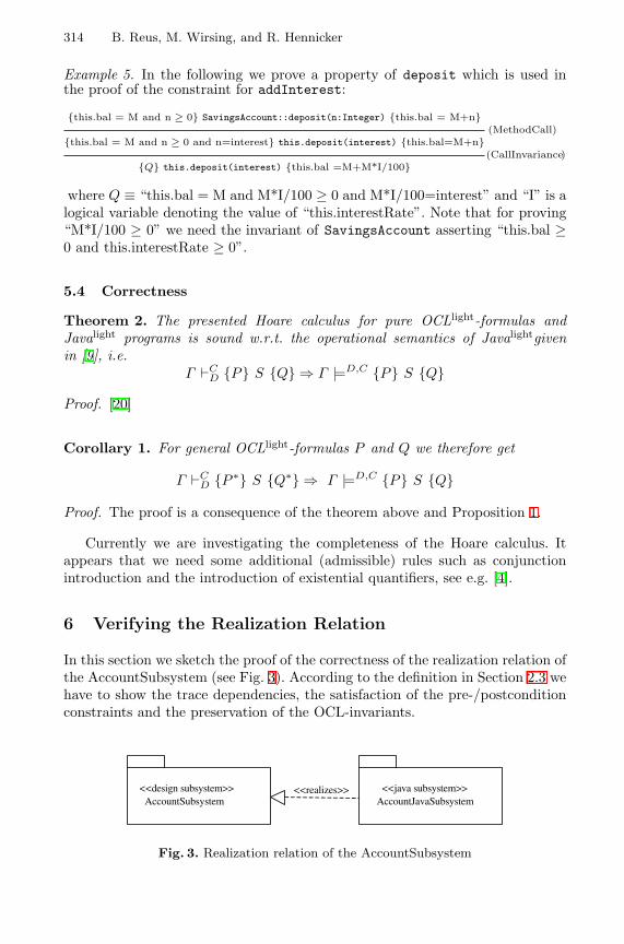
314 B. Reus, M. Wirsing, and R. Hennicker
Example 5. In the following we prove a property of deposit which is used inthe proof of the constraint for addInterest:
{this.bal = M and n ≥ 0} SavingsAccount::deposit(n:Integer) {this.bal = M+n}(MethodCall)
{this.bal = M and n ≥ 0 and n=interest} this.deposit(interest) {this.bal=M+n}(CallInvariance)
{Q} this.deposit(interest) {this.bal =M+M*I/100}
where Q ≡ “this.bal = M and M*I/100 ≥ 0 and M*I/100=interest” and “I” is alogical variable denoting the value of “this.interestRate”. Note that for proving“M*I/100 ≥ 0” we need the invariant of SavingsAccount asserting “this.bal ≥0 and this.interestRate ≥ 0”.
5.4 Correctness
Theorem 2. The presented Hoare calculus for pure OCLlight-formulas andJavalight programs is sound w.r.t. the operational semantics of Javalightgivenin [9], i.e.
Γ `CD {P} S {Q} ⇒ Γ |=D,C {P} S {Q}
Proof. [20]
Corollary 1. For general OCLlight-formulas P and Q we therefore get
Γ `CD {P ∗} S {Q∗} ⇒ Γ |=D,C {P} S {Q}
Proof. The proof is a consequence of the theorem above and Proposition 1.
Currently we are investigating the completeness of the Hoare calculus. Itappears that we need some additional (admissible) rules such as conjunctionintroduction and the introduction of existential quantifiers, see e.g. [4].
6 Verifying the Realization Relation
In this section we sketch the proof of the correctness of the realization relation ofthe AccountSubsystem (see Fig. 3). According to the definition in Section 2.3 wehave to show the trace dependencies, the satisfaction of the pre-/postconditionconstraints and the preservation of the OCL-invariants.
<<realizes>> <<java subsystem>>AccountJavaSubsystem
<<design subsystem>>AccountSubsystem
Fig. 3. Realization relation of the AccountSubsystem
A Hoare Calculus for Verifying Java Realizations 315
Trace dependencies. The trace dependencies are obviously satisfied: for eachclass of AccountSubsystem there exists a corresponding Java class in Accoun-tJavaSubsystem so that the attributes, methods and inheritance relations arepreserved.
Satisfaction of pre-/postconditions. The proof obligations (1-3) of Table 2 shownin Section 2.3 have to be verified. For this purpose, according to Corollary 1, itis sufficient to consider their transformations which can be proved as sketchedin Example 4 (for (1)), Example 3 (for (2)), and Example 5 (for (3)).
Preservation of invariants. The AccountSubsystem contains invariants for Sav-ingsAccount and CheckingAccount. It is easy to prove the associated conditions(4-6) shown in Section 2.3.
7 Concluding Remarks
We have presented a new formal approach for verifying the realization of UMLdesign models by Java subsystems and a new Hoare calculus for a sequentialsubset of Java and a subset of OCL as assertion language. This is a first steptowards the goal of providing a basis for formal software development with UML.But one can see several necessary extensions of our approach, for the UML partas well as for the Hoare calculus. In this paper we have restricted the designmodels to classes and their relationships. In the following we plan to consideralso interfaces. Here, our approach of [5] where we propose a constraint languagefor interfaces may provide a good basis for the extension. Another importantquestion concerns the composability of subsystems: Under which conditions isthe correctness of the realizes relationship preserved if two subsystems withcorrect realizations are composed? Concerning the Hoare calculus it should beeasy to extend semantics, calculus, and soundness proof to the full OCL-language(with bags, sequences and many operations on them). In order to analyse thepracticability of our calculus we also need to carry out further case studies. Thoseexamples might then propose additional admissible or derived proof-rules for theHoare calculus in order to support the verification process, i.e. to simplify thereasoning.
Acknowledgement. Thanks to Hubert Baumeister for useful discussions onthe realization relation and Alexander Knapp for helping with the conversion ofthe diagrams.
References
1. M. Abadi and K.R.M. Leino. A logic of object-oriented programs. In Michel Bidoitand Max Dauchet, editors, Theory and Practice of Software Development: Proceed-ings / TAPSOFT ’97, 7th International Joint Conference CAAP/FASE, volume1214 of Lecture Notes in Computer Science, pages 682–696. Springer-Verlag, 1997.
316 B. Reus, M. Wirsing, and R. Hennicker
2. J. Alves-Foss, editor. Formal Syntax and Semantics of Java, volume 1523 of Lect.Notes Comp. Sci. Springer, Berlin, 1999.
3. K.R. Apt. Ten Years of Hoare’s Logic: A Survey – Part I. TOPLAS, 3(4):431–483,1981.
4. K.R. Apt and E.R. Olderog. Verification of Sequential and Concurrent Programs.Springer, 1991.
5. M. Bidoit, R. Hennicker, F. Tort, and M. Wirsing. Correct realizations of interfaceconstraints with OCL. In UML’99, The Unified Modeling Language - Beyond theStandard, Fort Collins, USA, volume 1723 of Lecture Notes in Computer Science.Springer-Verlag, 1999.
6. R. Bornat. Pointer aliasing in Hoare logic. In Mathematics of Program Construc-tion, volume 1837 of Lecture Notes in Computer Science, pages 102–126. Springer-Verlag, 2000.
7. C. Calcagno, S. Ishtiaq, and P.W. O’Hearn. Semantic analysis of pointer aliasing,allocation and disposal in Hoare logic. In Principles and Practice of DeclarativeProgramming. ACM Press, 2000.
8. P. Cenciarelli, A. Knapp, B. Reus, and M. Wirsing. From Sequential to Multi-Threaded Java: An Event-Based Operational Semantics. In M. Johnson, editor,Proc. 6th Int. Conf. Algebraic Methodology and Software Technology, volume 1349of Lect. Notes Comp. Sci., pages 75–90, Berlin, 1997. Springer.
9. P. Cenciarelli, A. Knapp, B. Reus, and M. Wirsing. An Event-Based StructuralOperational Semantics of Multi-Threaded Java. In Alves-Foss [2], pages 157–200.
10. F.S. de Boer. A WP-calculus for OO. In W. Thomas, editor, Foundations ofSoftware Science and Computations Structures, volume 1578 of Lecture Notes inComputer Science. Springer-Verlag, 1999.
11. D. D’Souza and A.C. Wills. Objects, components and frameworks with UML: theCatalysis approach. Addison–Wesley, Reading, Mass., etc., 1998.
12. James Gosling, Bill Joy, and Guy Steele. The Java Language Specification.Addison–Wesley, Reading, Mass., 1996.
13. C.A.R. Hoare. An axiomatic basis for computer programming. Comm. ACM,12:576–583, 1969.
14. Gary T. Leavens, K. Rustan M. Leino, Erik Poll, Clyde Ruby, and Bart Jacobs.JML: notations and tools supporting detailed design in Java. In Object OrientedProgramming: Systems, Languages and Applications (OOPSLA), volume 35, pages208–228. ACM SIGPLAN Notices, 2000.
15. K. Rustan M. Leino. Ecstatic: An object-oriented programming language with anaxiomatic semantics. Technical Report KRML 65-0, SRC, 1996.
16. B. Liskov and J. Wing. A behavioral notion of subtyping. ACM Transactions onProgramming Languages and Systems, 16(6):1811–1841, 1994.
17. Object Management Group. Unified Modeling Language – Object Con-straint Language Specification. Technical report, available at http://www-4.ibm.com/software/ad/standards/ad970808 UML11 OCL.pdf, 1998.
18. A. Poetzsch-Heffter and P. Muller. A logic for the verification of object-orientedprograms. In R. Berghammer and F. Simon, editors, Programming Languagesand Fundamentals of Programming, Lecture Notes in Computer Science. Springer-Verlag, 1997.
19. A. Poetzsch-Heffter and P. Muller. A programming logic for sequential Java. InS. D. Swierstra, editor, European Symposium on Programming (ESOP), LectureNotes in Computer Science. Springer-Verlag, 1999.
20. B. Reus and M. Wirsing. A Hoare-Logic for Object-oriented Programs. Technicalreport, LMU Munchen, 2000.

A Hoare Calculus for Verifying Java Realizations 317
21. J. Rumbaugh, I. Jacobson, and G. Booch. The Unified Modeling Language Refer-ence Manual. Addison–Wesely, Reading, Mass., etc., 1998.
22. D. von Oheimb. Hoare logic for mutual recursion and local variables. In V. RamanC. Pandu Rangan and R. Ramanujam, editors, Found. of Software Techn. andTheoret. Comp. Sci., volume 1738 of LNCS, pages 168–180. Springer, 1999.
23. J. Warmer and A. Kleppe. The Object Constraint Language. Addison–Wesley,Reading, Mass., etc., 1999.
A Formal Object-Oriented Analysis for SoftwareReliability: Design for Verification
Natasha Sharygina1, James C. Browne2, and Robert P. Kurshan1
1 Bell Laboratories, 600 Mountain Ave.,Murray Hill, NJ, USA 07974
{natali,k}@research.bell-labs.com2 The University of Texas at Austin, Computer Science Department,
Austin, TX, USA [email protected]
Abstract. This paper presents the OOA design step in a methodology which in-tegrates automata-based model checking into a commercially supported OO soft-ware development process. We define and illustrate a set of design rules for OOAmodels with executable semantics, which lead to automata models with tractablestate spaces. The design rules yield OOA models with functionally structureddesigns similar to those of hardware systems. These structures support model-checking through techniques known to be feasible for hardware. The formal OOAmethodology, including the design rules, was applied to the design of NASA robotcontrol software. Serious logical design errors that had eluded prior testing, werediscovered in the course of model-checking.
1 Introduction
Problem Statement. Software systems used for control of modern devices are typ-ically both complex and concurrent. Object-Oriented (OO) development methods areincreasingly employed to cope with the complexity of these software systems. OO de-velopment systems still largely depend on conventional testing to validate correctness ofsystem behaviors, however. This is simply not adequate to attain the needed reliability,for complex systems, on account of the intrinsic incompleteness of conventional testing.
Formal verification of system behavior through model checking [4], on the otherhand, formally verifies that a given system satisfies a desired behavioral property throughexhaustive search of ALL states reachable by the system. Model checking has beenwidely and successfully applied to verification of hardware systems. Application ofmodel checking to software systems, has, in contrast, been much less successful. Toapply model checking to software systems the software systems must be translated fromprogramming or specification languages to representations to which model checking canbe applied. The resulting representation for model checking must have a tractable statespace if model checking is to be successful. Translation of software systems designed byconventional development processes and even by OO development processes to repre-sentations to which model checking can be applied have generally resulted in very largeinterconnected state spaces.
H. Hussmann (Ed.): FASE 2001, LNCS 2029, pp. 318–332, 2001.c© Springer-Verlag Berlin Heidelberg 2001
Design for Verification 319
A principal result reported in this paper is a set of design rules (Section 3) fordevelopment of OO software systems that when translated to representations to whichmodel checking can be applied, yield manageable state spaces. These design rules arethe critical initial step in the methodology for integration of formal verification by modelchecking into OO development processes.
Approach. The validity and usefulness of design rules and the effectiveness of theintegration of formal verification into object-oriented software development can be eval-uated only in the context of their application.
This paper reports a case study in re-engineering the control subsystem for a NASArobotics software system. The goal of the project was to increase the subsystem’s reliabil-ity. This goal was achieved, as serious logical design errors were discovered, through theapplication of model-checking. This case study motivates and demonstrates the designrules for "design for verifiability" and the application of formal verification by modelchecking to a substantial software system.
The robot control subsystem was originally implemented by a conventional devel-opment process in a procedural OO programming language (C++) generally followingthe Booch methodology [1]. In the re-engineering project, a four-step process to obtaina reliable system was planned:
1. Re-implement the control subsystem as an executable specification in the formof an Object-Oriented Analysis (OOA) model (in the Shlaer-Mellor (SM) methodology[26]);
2. Validate this executable specification as thoroughly as possible by testing;3. Apply model checking to the OOA model to validate its behavior at all possible
states of the system;4. Generate the control software by compilation of the validated and verified OOA
model.The application of the SM OOA method captures the robotic domain entities in
terms of classes/objects and relate them using the relationships diagrams. Testing andevaluation of the execution behavior of the constructed system was greatly simplified dueto the fact that the OOA classes were represented as a set of attributes, confined to simpletypes, and that the behavior of the system was state machine specified. Such an OOAmodel can be viewed as being designed for testability. This executable specification canalso be translated by a code generation system to C++ code. A commercially supportedsoftware system, SES/Objectbench (OB) [25] was used in this step.
OOA models with executable semantics are representations of software system,which should be amenable to model-based verification techniques. An OOA modelrepresents the program at a higher level of abstraction than a conventional program-ming language. The OOA model partitions the system into well-defined classes. But,attempts to apply model checking to these apparently highly modular OOA models ledto intractably large state spaces for the robot control system model. The cause for thisproblem is suggested by examining hardware systems. In hardware, the “calling” moduleand “called” module are separated spatially and communicate through a clean interfaceand a specified protocol. This “spatial modularity” supports divide-and-conquer ana-lytical techniques, as each module can be analyzed in isolation. This is essential forsuccessful model-checking because it resolves a fundamental problem of the state space
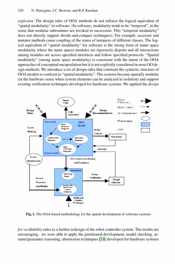
320 N. Sharygina, J.C. Browne, and R.P. Kurshan
explosion. The design rules of OOA methods do not enforce the logical equivalent of“spatial modularity” in software. (In software, modularity tends to be “temporal”, in thesense that modular subroutines are invoked in succession. This “temporal modularity”does not directly support divide-and-conquer techniques). For example, accessor andmutator methods cause coupling of the states of instances of different classes. The log-ical equivalent of “spatial modularity” for software is the strong form of name spacemodularity where the name spaces modules are rigorously disjoint and all interactionsamong modules are across specified interfaces and follow specified protocols. “Spatialmodularity” (strong name space modularity) is consistent with the intent of the OOAapproaches of conceptual encapsulation but it is not explicitly considered in most OO de-sign methods. We introduce a set of design rules that constrain the syntactic structure ofOOA models to conform to “spatial modularity”. The systems become spatially modular(in the hardware sense when system elements can be analyzed in isolation) and supportexisting verification techniques developed for hardware systems. We applied the design
Fig. 1. The OOA-based methodology for the spatial development of software systems
for verifiability rules to a further redesign of the robot controller system. The results areencouraging - we were able to apply the partitioned development, model checking, as-sume/guarantee reasoning, abstraction techniques [14] developed for hardware systems
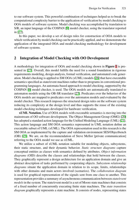
Design for Verification 321
to our software system. This powerful combination of techniques helped us to break thecomputational complexity barrier to the application of verification by model checking toOOA models of software systems. Model checking was accomplished by translation toS/R, an input language of the COSPAN [9] model checker, using the translator reportedin [27].
In this paper, we develop a set of design rules for construction of OOA models towhich verification by model checking can be practically applied, and we demonstrate theapplication of the integrated OOA and model-checking methodology for developmentof software systems.
2 Integration of Model Checking with OO Development
A methodology for integration of OOA and model checking shown in Figure 1 is pre-sented in [27]. Overall, this model fulfills the need for a sound foundation in rigorousrequirements modeling, design analysis, formal verification, and automated code gener-ation. Model checking is applied to SM OOA (xUML) models [26] that have executablesemantics specified as state/event machines rather than to programs in conventional pro-gramming languages. An automata-based approach to model checking, supported by theCOSPAN [9] model checker, is used. The OOA models are automatically translated toautomaton models using the OB-SR translator [27]. Predicates over the behavior of theOOA models are mapped to predicates over the automaton models and evaluated by themodel checker. This research imposes the structural design rules on the software systemreducing its complexity at the design level and thus supports the reuse of the existingmodel-checking techniques developed for hardware verification.
xUML Notation. Use of OOA models with executable semantics is moving into themainstream of OO software development. The Object Management Group (OMG) [20]has adopted a standard action language for the Unified Modeling Language (UML) [21].This action language and SM OOA semantics represented in UML notation define anexecutable subset of UML (xUML). The OOA representation used in this research is theSM OOA as implemented by the capture and validation environment SES/Objectbench(OB) [25]. We are, on the recommendation of Steve Mellor [private communication]referring to the OOA model we use as xUML.
We utilize a subset of xUML notation suitable for modeling objects, subsystems,their static structure, and their dynamic behavior. Static structure diagrams captureconceptual entities as classes with semantics defined by attributes. Object informationdiagrams (OID) describe the classes and relationships that hold between the classes.They graphically represent a design architecture for an application domain and give anabstract description of tasks performed by cooperating objects. Subsystem relationshipdiagrams situate the application domain in relation to its scope, limits, relationshipswith other domains and main actors involved (scenarios). The collaboration diagramis used for graphical representation of the signals sent from one class to another. Thisrepresentation provides a summary of asynchronous communication between state/eventmodels in the system. The state/event model is a set of Moore state machines that consistsof a fixed number of concurrently executing finite state machines. The state transitiondiagram graphically represents a state machine. It consists of nodes, representing states
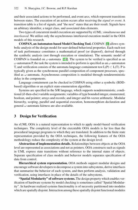
322 N. Sharygina, J.C. Browne, and R.P. Kurshan
and their associated actions to be performed, and event arcs, which represent transitionsbetween states. The execution of an action occurs after receiving the signal or event. Atransition table is a list of signals, and "the next" states that are their result. Signals havean arbitrary identifier, a target class, and associated data elements.
Two types of concurrent model execution are supported by xUML: simultaneous andinterleaved. We utilize only the asynchronous interleaved execution model in the OOAmodels of this research.
COSPAN, an Automaton-based Model Checking Tool. COSPAN [9] allows sym-bolic analysis of the design model for user-defined behavioral properties. Each such testof task performance constitutes a mathematical proof (or disproof), derived throughthe symbolic analysis (not through execution or simulation). The semantic model ofCOSPAN is founded on ω-automata [14]. The system to be verified is specified as anω-automaton P, the task the system is intended to perform is specified as an ω-automatonT, and verification consists of the automata language containment test L(P) ⊂ L(T). P istypically given as the synchronous parallel composition of component processes, spec-ified as ω-automata. Asynchronous composition is modeled through nondeterministicdelay in the components.
Language containment can be checked in COSPAN using either a symbolic (BDD-based) algorithm or an explicit state-enumeration algorithm.
Systems are specified in the S/R language, which supports nondeterministic, condi-tional (if-then-else) variable assignments; variables of type bounded integer, enumerated,boolean, and pointer; arrays and records; and integer and bit-vector arithmetic. Modularhierarchy, scoping, parallel and sequential execution, homomorphism declaration andgeneral ω-automata fairness are also available.
3 Design for Verification
An xUML OOA is a natural representation to which to apply model-based verificationtechniques. The complexity level of the executable OOA models is far less than theprocedural language programs to which they are translated. In addition to the finite staterepresentation provided by the OOA techniques, the following features of the OOAmethodology reduce the complexity of the system at the design level:
Abstraction of implementation details. Relationships between objects at the OOAlevel are represented as associations and not as pointers. OOA constructs such as signalsin UML express state transitions without reference to the internal states of objects.Separate specification of class models and behavior models separates specification ofdata from control.
Hierarchical system representation. OOA methods support modular designs andencourage software developers to decompose a system into subsystems, derive interfacesthat summarize the behavior of each system, and then perform analysis, validation andverification, using interfaces in place of the details of the subsystems.
“Spatial Modularity” of software systems. The design property which enables ver-ification of hardware systems by model checking is sometimes called “Spatial Modular-ity”. In hardware realized systems functionality is of necessity partitioned into moduleswhich are spatially disjoint. Interaction among these spatially disjoint functional modules
Design for Verification 323
must take place across precisely defined interfaces and follow precisely defined proto-cols. The spatial partitioning of hardware modules across well-defined static interfacessupports the application of divide-and-conquer techniques, necessary to circumvent thegenerally infeasible computation problem inherent in model-checking.
The logical equivalent of “spatial modularity” for software is the strong form ofname space modularity where the name spaces of all modules are disjoint and all inter-actions between functional modules are across specified interfaces and follow specifiedprotocols. The strong name space modularity is conceptually consistent with the method-ology of separation of concerns advocated by the OOA approaches. It is however is notexplicitly specified in any OO design methods.
Structural design rules. We developed a set of design rules and recommendationsthat constrain the structural design of the OOA models to conform to “spatial modu-larity”. The systems become spatially modular (in the hardware sense where systemelements can be analyzed in isolation) and support existing verification techniques de-veloped for hardware systems. These design rules for OOA models are similar to thosegiven for development of truly OO programs in OO procedural languages such as C++.
Design Rule 1. Write access to attributes of one class by another class must be madethrough the event mechanism.
The attributes of a class should be local to the class. Change of values of a class in-stance should be performed only through the event mechanism. This precludes couplingof internal states of classes.
Design Rule 2. Attribute values which are shared by multiple classes should bedefined in separate class and accessed only through the event mechanism.
This design rule also avoids coupling of internal states of classes.Design Rule 3. Declaration and definition of functional entities must be performed
within the same component.A component may have dependencies on other components. To prevent the situation
when functionality of one component can be changed by other components any logicalconstruct that a component declares should be defined entirely within that component.
Design Rule 4. Inheritance must be confined to extensions of supertypes. Modifica-tion of the behavior of supertypes (overriding of supertype methods) is prohibited.
This means to follow a meaning of subtyping, along the lines of Liskov’s [17]:“A type hierarchy is composed of subtypes and supertypes. The intuitive idea of a
subtype is one whose objects provide all the behavior of another type (the supertype)plus something extra. What is wanted here is something like the following substitutionproperty: If for every object o1: S there is o2: T such that for all programs P definedin terms of T, the behavior of P is unchanged when o1 is substituted for o2, then S is asubtype of T”.
Rule 4 enables reasoning about the correctness of newly derived subtype classesbased on the verification results of previously existing subtype classes.
Recommendation. Creating modular systems the linking between the modules/ sub-systems should be minimized.
Subsystems are fundamentally open systems but for verification must be closed with adefinition of the environment in which they will execute. Simulation of the environmentbehavior is performed by assuming a sequence of events defined on the subsystem’s
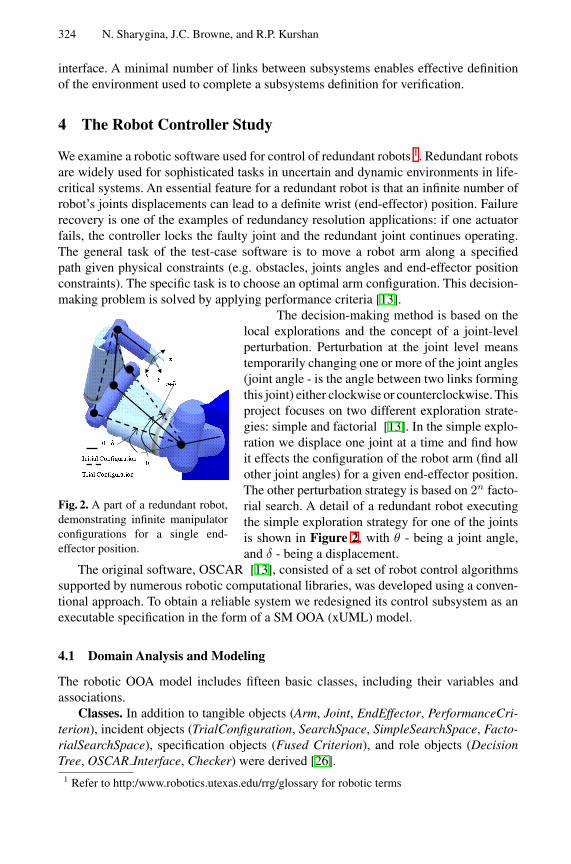
324 N. Sharygina, J.C. Browne, and R.P. Kurshan
interface. A minimal number of links between subsystems enables effective definitionof the environment used to complete a subsystems definition for verification.
4 The Robot Controller Study
We examine a robotic software used for control of redundant robots 1. Redundant robotsare widely used for sophisticated tasks in uncertain and dynamic environments in life-critical systems. An essential feature for a redundant robot is that an infinite number ofrobot’s joints displacements can lead to a definite wrist (end-effector) position. Failurerecovery is one of the examples of redundancy resolution applications: if one actuatorfails, the controller locks the faulty joint and the redundant joint continues operating.The general task of the test-case software is to move a robot arm along a specifiedpath given physical constraints (e.g. obstacles, joints angles and end-effector positionconstraints). The specific task is to choose an optimal arm configuration. This decision-making problem is solved by applying performance criteria [13].
The decision-making method is based on the
Fig. 2. A part of a redundant robot,demonstrating infinite manipulatorconfigurations for a single end-effector position.
local explorations and the concept of a joint-levelperturbation. Perturbation at the joint level meanstemporarily changing one or more of the joint angles(joint angle - is the angle between two links formingthis joint) either clockwise or counterclockwise. Thisproject focuses on two different exploration strate-gies: simple and factorial [13]. In the simple explo-ration we displace one joint at a time and find howit effects the configuration of the robot arm (find allother joint angles) for a given end-effector position.The other perturbation strategy is based on 2n facto-rial search. A detail of a redundant robot executingthe simple exploration strategy for one of the jointsis shown in Figure 2, with θ - being a joint angle,and δ - being a displacement.
The original software, OSCAR [13], consisted of a set of robot control algorithmssupported by numerous robotic computational libraries, was developed using a conven-tional approach. To obtain a reliable system we redesigned its control subsystem as anexecutable specification in the form of a SM OOA (xUML) model.
4.1 Domain Analysis and Modeling
The robotic OOA model includes fifteen basic classes, including their variables andassociations.
Classes. In addition to tangible objects (Arm, Joint, EndEffector, PerformanceCri-terion), incident objects (TrialConfiguration, SearchSpace, SimpleSearchSpace, Facto-rialSearchSpace), specification objects (Fused Criterion), and role objects (DecisionTree, OSCAR Interface, Checker) were derived [26].
1 Refer to http:/www.robotics.utexas.edu/rrg/glossary for robotic terms
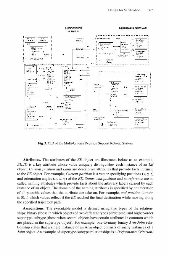
Design for Verification 325
Fig. 3. OID of the Multi-Criteria Decision Support Robotic System
Attributes. The attributes of the EE object are illustrated below as an example.EE ID is a key attribute whose value uniquely distinguishes each instance of an EEobject. Current position and Limit are descriptive attributes that provide facts intrinsicto the EE object. For example, Current position is a vector specifying positions (x, y, z)and orientation angles (α, β, γ) of the EE. Status, end position and ee reference are socalled naming attributes which provide facts about the arbitrary labels carried by eachinstance of an object. The domain of the naming attributes is specified by enumerationof all possible values that the attribute can take on. For example, end position domainis (0,1) which values reflect if the EE reached the final destination while moving alongthe specified trajectory path.
Associations. The executable model is defined using two types of the relation-ships: binary (those in which objects of two different types participate) and higher-ordersupertype-subtype (those when several objects have certain attributes in common whichare placed in the supertype object). For example, one-to-many binary Arm-Joint rela-tionship states that a single instance of an Arm object consists of many instances of aJoint object. An example of supertype-subtype relationships is a PerformanceCriterion-
326 N. Sharygina, J.C. Browne, and R.P. Kurshan
ConstraintCriterion relationship. In this construct one real-world instance is presentedby the combination of an instance of the supertype and an instance of exactly one subtype.
Robotic Decision-Support Domain Architecture. The application domain archi-tecture was divided into computational and optimization subsystems. The input for theoptimization subsystem is one or more trial arm configurations from which the opti-mization system will either select the best one or provide the computational system withsuggestions on what an optimal arm configuration should be.
The computational subsystem includes kinematics algorithms and interfaces to thecomputational libraries of the OSCAR system. There are two methods for the compu-tational system to define a base point of the optimization search. The first method is tocalculate an EndEffector (EE) position given initial Joint (J) angles of all joints and,thus, find an initial arm configuration. The second method depicts an EE position as anew base point from the Trajectory path specified by the user.
A collaboration diagram of the abstracted Kinematics unit which verification resultswe discuss in the next section is represented in Figure 6. The control algorithm startswith defining an initial end-effector position given the initial joint angles. This is doneby solving a forward kinematics problem [13]. The next step is to get a new end-effectorposition from a predefined path. The system calculates the joint angles for this position,providing the solution of the inverse kinematics problem [13] and configures the arm. Ateach of the steps described above, a number of physical constraints has to be satisfied.The constraints include limits on the angles of joints. If a joint angle limit is not satisfied,a fault recovery is performed. The faulty joint is locked within the limit value. Then, thevalue of the angle of another joint is recalculated for the same end-effector position. If theend-effector position exceeds the limit, the algorithm registers the undesired position,which serves as a flag to stop the execution. A Checker class controls the joints that passor fail the constraints check. If all the joints meet the constraints, the Checker issues thecommand to move the end-effector to a new position. Otherwise it either starts a faultrecovery algorithm or stops execution of the program (if fault recovery is not possible).
The optimization subsystem implements the decision-making strategy by applyingdecision-making techniques identifying a solution to the multi-criteria problem. It buildsa SearchSpace (SS), which generates sets of JointConfigurations (JC) around a base pointsupplied by the computational subsystem. JC instances initiate creation of TrialConfig-uration (TC) instances that normalize a robot arm configuration for any perturbed joint.A DecisionTree (DT) selects the best TC given a set of PerformanceCriteria (PC) anda number of physical constraints that are globally defined by the user. The found solu-tion serves as the next base point for another pattern of local exploration. The searchstops when no new solutions are found. The system returns control to the computationalsubsystem which changes the position of the EE following the specified trajectory anddetermines a new base point for the search.
4.2 Compliance to the Design Rules
During the construction of the robot control design we followed the design rules specifiedin Section 3.
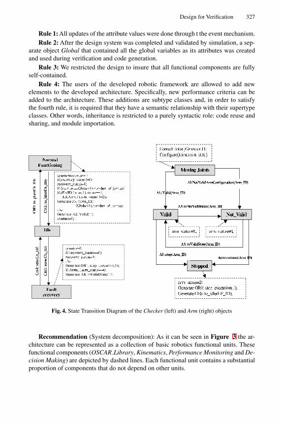
Design for Verification 327
Rule 1: All updates of the attribute values were done through t the event mechanism.Rule 2: After the design system was completed and validated by simulation, a sep-
arate object Global that contained all the global variables as its attributes was createdand used during verification and code generation.
Rule 3: We restricted the design to insure that all functional components are fullyself-contained.
Rule 4: The users of the developed robotic framework are allowed to add newelements to the developed architecture. Specifically, new performance criteria can beadded to the architecture. These additions are subtype classes and, in order to satisfythe fourth rule, it is required that they have a semantic relationship with their supertypeclasses. Other words, inheritance is restricted to a purely syntactic role: code reuse andsharing, and module importation.
Fig. 4. State Transition Diagram of the Checker (left) and Arm (right) objects
Recommendation (System decomposition): As it can be seen in Figure 3 the ar-chitecture can be represented as a collection of basic robotics functional units. Thesefunctional components (OSCAR Library, Kinematics, Performance Monitoring and De-cision Making) are depicted by dashed lines. Each functional unit contains a substantialproportion of components that do not depend on other units.
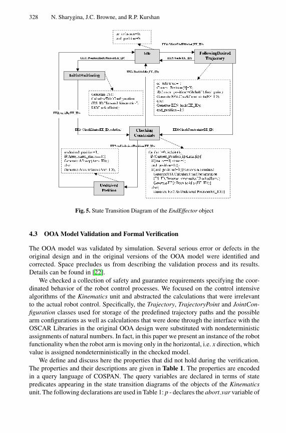
328 N. Sharygina, J.C. Browne, and R.P. Kurshan
Fig. 5. State Transition Diagram of the EndEffector object
4.3 OOA Model Validation and Formal Verification
The OOA model was validated by simulation. Several serious error or defects in theoriginal design and in the original versions of the OOA model were identified andcorrected. Space precludes us from describing the validation process and its results.Details can be found in [22].
We checked a collection of safety and guarantee requirements specifying the coor-dinated behavior of the robot control processes. We focused on the control intensivealgorithms of the Kinematics unit and abstracted the calculations that were irrelevantto the actual robot control. Specifically, the Trajectory, TrajectoryPoint and JointCon-figuration classes used for storage of the predefined trajectory paths and the possiblearm configurations as well as calculations that were done through the interface with theOSCAR Libraries in the original OOA design were substituted with nondeterministicassignments of natural numbers. In fact, in this paper we present an instance of the robotfunctionality when the robot arm is moving only in the horizontal, i.e. x direction, whichvalue is assigned nondeterministically in the checked model.
We define and discuss here the properties that did not hold during the verification.The properties and their descriptions are given in Table 1. The properties are encodedin a query language of COSPAN. The query variables are declared in terms of statepredicates appearing in the state transition diagrams of the objects of the Kinematicsunit. The following declarations are used in Table 1: p - declares the abort var variable of
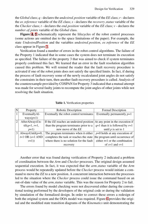
Design for Verification 329
the Global class; q - declares the undesired position variable of the EE class; r - declaresthe ee reference variable of the EE class; s - declares the recovery status variable of thethe Checker class; t - declares the end position variable of the EE class; v - declares thenumber of joints variable of the Global class.
Figure 4, 5 schematically represent the lifecycles of the robot control processes(some actions are omitted due to the space limitations of the paper). For example, thestate UndesiredPosition and the variables undesired position, ee reference of the EEclass appear in Figure 5.
Verification found a number of errors in the robot control algorithms. The failure ofthe Property 1 indicated that in some cases the system does not terminate its executionas specified. The failure of the property 3 that was aimed to check if system terminatesproperly confirmed this fact. We learned that an error in the fault resolution algorithmcaused this problem. We will remind the reader that the fault recovery procedure isactivated if one of the robot joints does not satisfy the specified limits. In fact, if duringthe process of fault recovery some of the newly recalculated joint angles do not satisfythe constraints in their turn, then another fault recovery procedure is called. Analysis ofthe counterexample provided by COSPAN for Property 3 indicated that a mutual attemptwas made for several faulty joints to recompute the joint angles of other joints while notresolving the fault situation.
Table 1. Verification properties
N Property Robotic Description Formal Description1 EventuallyAl-
ways(p=1)Eventually the robot control terminates Eventually permanently p=1
2 AfterAlwaysUn-til(q=1, r=1,
p=1)
If the EE reaches an undesired positionthan the program terminates prior to a
new move of the EE
At any point in the execution ifq=1 than it is followed by r=1
until p is set to 13 AlwaysUntil(p=0,
t=1 OR (s=1 ANDv=1))
The program terminates when it eithercompletes the task or reaches the statewhere there is no solution for the fault
recovery
p=0 holds at any execution ofthe program until occurrence ofeither t=1 or the combination
of s=1 and v=1
Another error that was found during verification of Property 2 indicated a problemof coordination between the Arm and Checker processes. The original design assumedsequential execution. In fact, it was expected that the arm status variable of the Armprocess would be repeatedly updated before the Checker process would initiate a com-mand to move the EE to a new position. A concurrent interaction between the processesled to the situation where the Checker process could issue the command based on anout-of-date value of the arm status variable. This was the reason for Property 2 to fail.
The errors found by model checking were not discovered either during the conven-tional testing performed by the developers of the original code or during the validationby simulation of the formalized design. In order to correct these errors a redesign ofboth the original system and the OOA model was required. Figure 6 provides the origi-nal and the modified state transition diagrams of the Kinematics unit demonstrating the
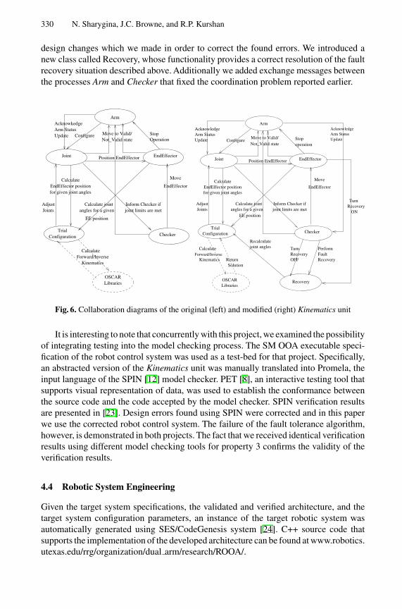
330 N. Sharygina, J.C. Browne, and R.P. Kurshan
design changes which we made in order to correct the found errors. We introduced anew class called Recovery, whose functionality provides a correct resolution of the faultrecovery situation described above. Additionally we added exchange messages betweenthe processes Arm and Checker that fixed the coordination problem reported earlier.
Move
EndEffector
Calculate jointangles for a given
EE position
for given joint angles
OSCAR
TrialConfiguration Checker
CalculateEndEffector position
Inform Checker if
AcknowkedgeArm StatusUpdate Move to Valid/
Not_Valid state
Libraries
joint limits are metAdjustJoints
CalculateForward/Inverse
Kinematics
Position EndEffector
Stop Operation
Arm
Configure
EndEffectorJoint
KinematicsSolution
Return
Recovery
Turnjoint anglesRecalculate
EE position
Calculate
Inform Checker ifangles for a given
Calculate joint
EndEffector
joint limits are met
LibrariesOSCAR
JointsAdjust
Recovery
Stop operation
Move to Valid/Not_Valid state
Forward/Inverse
UpdateArm StatusAcknowledge
Update
ONRecoveryTurn
OFF
Perform
Arm StatusAcknowledge
RecoveryFault
Move
Joint Position EndEffector
TrialConfiguration
for given joint anglesEndEffector position
Calculate
Checker
EndEffector
Configure
Arm
Fig. 6. Collaboration diagrams of the original (left) and modified (right) Kinematics unit
It is interesting to note that concurrently with this project, we examined the possibilityof integrating testing into the model checking process. The SM OOA executable speci-fication of the robot control system was used as a test-bed for that project. Specifically,an abstracted version of the Kinematics unit was manually translated into Promela, theinput language of the SPIN [12] model checker. PET [8], an interactive testing tool thatsupports visual representation of data, was used to establish the conformance betweenthe source code and the code accepted by the model checker. SPIN verification resultsare presented in [23]. Design errors found using SPIN were corrected and in this paperwe use the corrected robot control system. The failure of the fault tolerance algorithm,however, is demonstrated in both projects. The fact that we received identical verificationresults using different model checking tools for property 3 confirms the validity of theverification results.
4.4 Robotic System Engineering
Given the target system specifications, the validated and verified architecture, and thetarget system configuration parameters, an instance of the target robotic system wasautomatically generated using SES/CodeGenesis system [24]. C++ source code thatsupports the implementation of the developed architecture can be found at www.robotics.utexas.edu/rrg/organization/dual arm/research/ROOA/.
Design for Verification 331
5 Conclusions and Related Work
This paper gives a feasibility demonstration for the application of verification by modelchecking to a substantial control intensive application developed in a commercially sup-ported and widely used OO development process. The results of the demonstration arehighly encouraging. Verification of significant behavioral properties of the robot controlsubsystem were carried out. The importance of verification to OOA model design anddevelopment has been shown. Design rules leading to xUML OOA models to which ver-ification by model checking can be practically applied have been proposed and applied.
Previous work on application of model checking to software systems has mainly beeneither to software systems written in procedural languages or to abstract models extractedfrom programs in procedural languages. Feaver [11] targets software systems writtenin C while [2], [3] focus on applying model checking on SDL programs. Havelund andPressburger [10] apply model checking to Java programs. Corbett, et.al [5] extract finitestate machines from Java programs to which to apply model checking. The results ofverification of a safety critical railroad control system which complexity is comparableto our test-case study are presented in [7].
Model-checking has been also applied to verification of concurrently executingstate/event machines. Lind-Nielsen, et al. [16] applied SMV [18] for verification ofhardware systems represented by VisualState state machines. Dependency analysis wasused to decompose a large but naturally spatially modular systems. Chan, et al. [6] ver-ified a complex aircraft collision software. They reported that their ad hoc solutions forthe manual system partitioning frequently caused invalid results. None approaches theissues of the system redesign prior to model-checking.
Design guidelines for constructing testable and maintainable programs in object-oriented procedural languages have been proposed and discussed by a number of re-searchers [15], [17]. Moors [19] has proposed similar design criteria for communicationprotocols. However, there is no an effort known to us that would address a problem ofdeveloping the OOA design rules that support resolution of the state-explosion problemat the design level.
Acknowledgement. This research was partially supported by the Robotics ResearchGroup of the University of Texas at Austin.
References
1. Booch, G., Object-Oriented Analysis and Design with Applications, Benjamin/Cummings,Redwood City, CA (1994)
2. Bounimova, E., Levin, V., Basbugoglu, O., and Inan, K., A Verification Engine for SDL Spec.Of Comm. Protocols, In Proc. of the 1st Symp. on Computer Networks, Istanbul, Turkey,(1996) 16-25
3. Bosnacki, D., Damm, D., Holenderski, L.,and Sidorova, N., Model checking SDL with Spin,In Proc. of TACAS2000, Berlin, Germany, (2000) 363-377
4. Clarke, E.M., and Emerson, E.A.: Design and synthesis of synchronization skeletons usingbranching time temporal logic,Workshop on Logic of Programs,Yorktown Heights, NY. LNCS,Vol. 131, (1981) 52-71
332 N. Sharygina, J.C. Browne, and R.P. Kurshan
5. Corbett, J., Dwyer, M., Hatcliff, J., Laubach, S., Pasareanu, C., Bandera: Extracting finite-statemodels for Java source code, In Proc. of 22nd ICSE (2000)
6. Chan, W., Anderson, R., Beame, P., Burns, S., Modugno, F., Notkin, D., Reese, J., ModelChecking Large Software Specifications, In Proc. of IEEE Transaction on Software Engi-neering (1998) 498-519
7. Gnesi, S., Lenzini, G.,Abbaneo, C., Latella, D.,Amendola,A., Marmo, P.,AnAutomatic SPINValidation of a Safety Critical Railway Control System, In Proc. of Int. Conf. on DependableSystems and Networks, (2000) 119-124
8. Gunter, E., and Peled D., Path Exploration Tool, In Proc. of TACAS 1999, Amsterdam, TheNetherlands (1999) 405-419
9. Hardin R., Har’El, Z., and Kurshan, R.P., COSPAN, In Proc., CAV’96, LNCS, Vol. 1102,(1996) 423-427
10. Havelund, K., and Pressburger, T., Model Checking Java Programs Using Java PathFinder, InProc. 4’th SPIN workshop (1998)
11. Holzmann, G., and Smith, M., Feaver: Automating software feature verification, Bell LabsTechnical Journal, Vol. 5, 2, (2000) 72-87
12. Holzmann, G., The Model Checker SPIN, IEEE Trans. on Software Engineering, Vol. 5(23),(1997) 279-295
13. Kapoor, C., and Tesar, D.: A Reusable Operational Software Architecture for AdvancedRobotics (OSCAR), The University of Texas at Austin, Report to DOE, Grant No. DE-FG0194EW37966 and NASA Grant No. NAG 9-809 (1998)
14. Kurshan, R., Computer-Aided Verification of Coordinating Processes - The Automata-Theoretic Approach, Princeton University Press, Princeton, NJ (1994)
15. Lano, K., Formal Object-Oriented Development, Springer (1997)16. Lind-Nielsen, J, Andersen H., R., etc., Verification of large State/Event Systems using Com-
positionality and Depenedency Analysis, In Proc. of TACAS’98, Portugal (1998) 201-21617. Liskov, B., Data Abstraction and Hierarchy, In Proc. of OOPSLA conference (1987)18. McMillan, K. Symbolic Model Checking, Kluwer (1993)19. Moors, T., Protocol Organs: Modularity should reflect function, not timing, In Proc. OPE-
NARCH98, (1998) 91-10020. Object Management Group (OMG), Action Semantic for the UML, OMG (2000)21. Rumbaugh, J., Jacobson, I. and Booch, G., The Unified Modeling Language Reference Man-
ual, Object Technology Series, Addison-Wesley (1999)22. Sharygina, N., and Browne, J., Automated Rob. Decision Support Software Reverse Engi-
neering, Tech. Rep., The Univ. of Texas at Austin, Robotics Research Croup (1999)23. Sharygina, N., and Peled, D., A Combined Testing and Verification Approach for Software
Reliability, In Proc. of FME2001 (to appear), Berlin (2001)24. SES Inc., CodeGenesis User Reference Manual, SES Inc. (1998)25. SES inc., ObjectBench Technical Reference, SES Inc. (1998)26. Shlaer, S., and Mellor, S., Object Lifecycles: Modeling the World in States, Prentice-Hall, NJ
(1992)27. Xie, F., Levin, V., Browne, J., Integrating model checking into object-oriented software de-
velopment process, Techn.Rep., University of Texas at Austin, Comp. Science Dept. (2000)
Specification and Analysis of theAER/NCA Active Network Protocol Suite in
Real-Time Maude
Peter Csaba Olveczky1,4, Mark Keaton2, Jose Meseguer1,Carolyn Talcott3, and Steve Zabele2
1 Computer Science Laboratory, SRI International, Menlo Park, CA 940252 Litton-TASC Inc., Reading, MA 01867
3 Computer Science Department, Stanford University, Stanford, CA 943054 Department of Informatics, University of Oslo, Norway
Abstract. This paper describes the application of the Real-Time Maudetool and the Maude formal methodology to the specification and analy-sis of the AER/NCA suite of active network multicast protocol compo-nents. Because of the time-sensitive and resource-sensitive behavior andthe composability of its components, AER/NCA poses challenging newproblems for its formal specification and analysis. Real-Time Maude is anatural extension of the Maude rewriting logic language and tool for thespecification and analysis of real-time object-based distributed systems.It supports a wide spectrum of formal methods, including: executablespecification; symbolic simulation; and infinite-state model checking oftemporal logic formulas. These methods complement those offered byfinite-state model checkers and general-purpose theorem provers. Real-Time Maude has proved to be well-suited to meet the AER/NCA model-ing challenges, and its methods have been effective in uncovering subtleand important errors in the informal use case specification.
1 Introduction
This paper describes the application of the Real-Time Maude tool [14] and theMaude formal methodology [4] to the specification and analysis of the AER/NCAsuite of active network communication protocol components [8,1] which collec-tively implement a scalable and reliable multicast capability using active ele-ments in the network. Being a very advanced and sophisticated suite of protocolsthat run in a highly distributed and modular fashion, the AER/NCA suite poseschallenging new problems for formal specification and analysis including:
– Time-sensitive behavior, including delay, delay estimation, timers, ordering,and resource contention;
– Resource-sensitive behavior, including capacity, latency, congestion/cross-traffic, and buffering;
H. Hussmann (Ed.): FASE 2001, LNCS 2029, pp. 333–347, 2001.c© Springer-Verlag Berlin Heidelberg 2001
334 P.C. Olveczky et al.
– Both performance and correctness are critical metrics;– Composability issues: modeling and analyzing both individual protocol com-
ponents and their aggregate behavior; and supporting reuse for developingalternative protocols.
Maude is a language and high-performance system based on rewriting logic [3].As such it naturally supports specification and analysis of object-based dis-tributed systems by supporting a wide spectrum of formal methods [4,11], in-cluding executable specification; symbolic simulation; model checking; and for-mal proof. Real-Time Maude naturally extends Maude to support the aboveformal methodology to distributed real-time and hybrid systems [14,12].
Real-Time Maude has proved to be well-suited to meet the above challenges.The active network and performance aspects have been naturally addressed bythe flexibility of the Maude’s distributed object model that made it easy toinclude active elements and resources as objects. The time- and resource-sensitivebehavior is expressed naturally by timed rewrite rules. The composability issueswere well addressed by Maude’s support for multiple class inheritance.
The starting point of the formal specification effort was an informal specificationconsisting of a set of use cases. Although use cases are widely used as a softwaredesign technique, the experience gained from the present work indicates thatthey are not well suited for modeling complex distributed systems. To under-stand the system behavior, state transition diagrams had to be developed by theprotocol designers. The Maude specification provided a natural formalization ofthe informal state transition diagrams and followed closely the designers’ intu-itions. In hindsight, it seems clear that, for distributed applications of this kind,the executable state-transition style of the Maude specification is a much moreeffective starting point for an implementation than use cases.
The Maude formal methodology complements other formal methods approachessuch as model checking tools [7,2,9,18] and general purpose theorem provers [16,17,6]. It provides a flexible middle ground extending the advantages of modelchecking to a wide range of infinite state systems. Furthermore, the simple for-mal semantics of rewriting logic and the underlying equational and rewritingtechniques provide a natural basis for a range of automated and interactive de-duction techniques.
2 Specifying and Analyzing Real-Time Systems inRewriting Logic
In rewriting logic [10] distributed systems are specified by rewrite theories of theform (Σ,E ,R), with (Σ,E ) an equational theory specifying the system’s statespace as an algebraic data type, and R a collection of rewrite rules specifyingthe system’s local transitions. This specification style can be specialized to dis-tributed real-time and hybrid systems by using real-time rewrite theories [15].The Real-Time Maude language and tool [14,12] can then be used for specifying,simulating, and analyzing such systems.
The AER/NCA Active Network Protocol Suite in Real-Time Maude 335
2.1 Real-Time Rewrite Theories
In [15] we have proposed modeling real-time and hybrid systems in rewritinglogic as real-time rewrite theories. These are rewrite theories containing:
– a specification of a Time data type specifying the time domain;– a sort System with no subsorts, and a free constructor { } : State → System
(for State the sort of the global state) with the intended meaning that {t}denotes the whole system, which is in state t ;
– instantaneous rewrite rules that model instantaneous change and are as-sumed to take zero time; and
– tick (rewrite) rules that model the elapse of time on a system, and have theform
[l ] : {t(x1, . . . , xn)} τl (x1,... ,xn)−→ {t ′(x1, . . . , xn)} if cond ,
with τl(x1, . . . , xn) a term of sort Time denoting the rule’s duration. Theuse of the operator { } in the tick rules ensures uniform time advance bythe global state always having the form {t}.
In [15] we have shown that a wide range of models of real-time and hybrid systemscan be expressed quite naturally and directly as real-time rewrite theories. Wehave also shown in [15] that real-time rewrite theories can be reduced to ordinaryrewrite theories by adding an explicit clock to the global state in a way thatpreserves all their expected properties. This transformation introduces a newconstructor 〈 , 〉 : System Time → ClockedSystem, replaces each tick rule of theform [l ] : {t} τl−→ {t ′} if cond with a rule of the form [l ] : 〈 {t}, x 〉 −→ 〈 {t ′}, x+τl〉 if cond (for x a new variable), and leaves the rest of the theory unchanged.
2.2 Real-Time Maude
The Real-Time Maude specification language and analysis tool [12,14] is builton top of the rewriting logic language Maude [3]. Real-Time Maude supports thespecification of real-time rewrite theories in timed modules and object-orientedtimed modules, which are transformed into equivalent Maude modules.
2.3 Specifying Concurrent Objects
Real-Time Maude extends Full Maude [5,3]. We recall how concurrent objectsare specified in object-oriented modules in Full Maude. A class declaration
class C | att1 : s1, ... , attn : sn .
336 P.C. Olveczky et al.
declares a class C with attributes att1 to attn of sorts s1 to sn . An object of classC is represented as a term < O : C | att1 : val1, ..., attn : valn >, where O is theobject’s name or identifier, and where val1 to valn are the current values of theattributes att1 to attn . In a concurrent object-oriented system, the state, which isusually called a configuration, has typically the structure of a multiset made upof objects and messages, and where multiset union is denoted by an associativeand commutative juxtaposition operator (empty syntax). The dynamic behaviorof concurrent object systems is axiomatized by specifying each of its concurrenttransition patterns by a rewrite rule. For example, the rule
rl [l] : m(O,w) < O : C | a1 : x, a2 : y, a3 : z > =>< O : C | a1 : x + w, a2 : y, a3 : z > m’(y,x)
defines a (family of) transition(s) in which a message m having arguments O and wis consumed by an object O of class C, with the effect of altering the attribute a1 ofthe object and of generating a new message m’(y,x). By convention, attributes,such as a3 in our example, whose values do not change and do not affect thenext state of other attributes need not be mentioned in a rule. Attributes likea2 whose values influence the next state of other attributes or the values inmessages, but are themselves unchanged, may be omitted from righthand sides.
2.4 Specification of Object-Oriented Real-Time Systems
In Real-Time Maude, tick rules of the form [l ] : {t} τl−→ {t ′} if cond are writtenwith the syntax
crl [l] : {t} => {t′} in time τl if cond .
(and with similar syntax for unconditional rules). We recall here some of thetechniques outlined in [15] for specifying object-oriented real-time systems usedin this case study. Such systems are specified as timed object-oriented modulesin Real-Time Maude. The single tick rule in the AER/NCA specification is
var OC : ObjConf .crl [tick] : {OC} => {delta(OC, mte(OC))} in time mte(OC)
if mte(OC) =/= INF and mte(OC) =/= 0 .
The use of the variable OC of sort ObjConf (denoting configurations consistingof objects only) requires that the global state only consists of objects when thetick rule is applied, and therefore forces messages to be treated without delay,because the above rule will not match and therefore time will not advance whenthere are messages present in the state.
The function delta models the effect of time elapse on a state, the function mtedenotes the maximal time elapse possible before some instantaneous action mustbe taken, and INF is an infinity value. The functions delta and mte distributeover the objects in a configuration as follows:
The AER/NCA Active Network Protocol Suite in Real-Time Maude 337
op delta : Configuration Time -> Configuration .op mte : Configuration -> TimeInf .
vars NECF NECF’ : NEConfiguration . var R : Time .eq delta(none, R) = none .eq delta(NECF NECF’, R) = delta(NECF, R) delta(NECF’, R) .eq mte(none) = INF .eq mte(NECF NECF’) = min(mte(NECF), mte(NECF’)) .
To completely specify these functions, they must then be defined for single ob-jects as illustrated in Section 4.3.
2.5 Rapid Prototyping and Formal Analysis in Real-Time Maude
The Real-Time Maude analysis tool supports a wide range of techniques forformally analyzing timed modules which we summarize below.
Rapid Prototyping. The Real-Time Maude tool transforms timed modulesinto ordinary Maude modules that can be immediately executed using Maude’sdefault interpreter, which simulates one behavior—up to a given number ofrewrite steps to perform—from a given initial state. The tool also has a defaulttimed execution strategy which controls the execution by taking the elapsed timein the rewrite path into account.
Model Checking. Real-Time Maude provides a variety of search and modelchecking commands for further analyzing timed modules by exploring all possi-ble behaviors—up to a given number of rewrite steps, duration, or satisfaction ofother conditions—that can be nondeterministically reached from the initial state.In particular, the tool provides model checking facilities for model checking cer-tain classes of real-time temporal formulas [14]. In this paper we will model checktemporal properties of the form p UStable≤r p′, where p and p′ are patterns,and UStable≤r is a temporal “until/stable” operator. A pattern is either theconstant noTerm (which is not matched by any term), the constant anyPattern(which is matched by any term), a term (possibly) containing variables, or hasthe form t(x ) where cond(x ). The temporal property p UStable≤r p′ is satis-fied by a real-time rewrite theory with respect to an initial term t0 if and onlyif for each infinite sequence and each non-extensible finite sequence
〈t0, 0〉 −→ 〈t1, r1〉 −→ 〈t2, r2〉 −→ · · ·of one-step sequential ground rewrites [10] in the transformed “clocked” rewritetheory (see Section 2.1), there is a k with rk ≤ r such that tk matches p′, andti matches p for all 0 ≤ i < k , and, furthermore, if tj matches p′ then so does tlfor each l > j with rl ≤ r . That is, each state in a computation matches p untilp′ is matched for the first time (by a state with total time elapse less than orequal to r), and, in addition, p′ is matched by all subsequent states with totaltime elapse less than or equal to r .
338 P.C. Olveczky et al.
Application-Specific Analysis Strategies. A Real-Time Maude specifica-tion can be further analyzed by using Maude’s reflective features to defineapplication-specific analysis strategies. For that purpose, Real-Time Maude pro-vides a library of strategies—including the strategies needed to execute Real-Time Maude’s search and model checking commands—specifically designed foranalyzing real-time specifications. These strategies are available in the Real-Time Maude module TIMED-META-LEVEL, allowing the strategy library to bereused in modules importing TIMED-META-LEVEL. Section 5.2 gives an exampleof an application-specific strategy which was easily defined (in 35 lines of Maudecode) by reusing key functions from TIMED-META-LEVEL.
3 The AER/NCA Protocol Suite
The AER/NCA protocol suite [1,8] is a new and sophisticated protocol suitefor reliable multicast in active networks. The suite consists of a collection ofcomposable protocol components supporting active error recovery (AER) andnominee-based congestion avoidance (NCA) features, and makes use of the pos-sibility of having some processing capabilities at “active nodes” between thesender and the receivers to achieve scalability and efficiency.
The goal of reliable multicast is to send a sequence of data packets from a senderto a group of receivers. Packets may be lost due to congestion in the network,and it must be ensured that each receiver eventually receives each data packet.Existing multicast protocols are either not scalable or do not guarantee delivery.To achieve both reliability and scalability, Kasera et al. [8] have suggested the useof active services at strategic locations inside the network. These active servicescan execute application-level programs inside routers, or on servers co-locatedwith routers along the physical multicast distribution tree. By caching packets,these active services can subcast lost packets directly to “their” receivers, therebylocalizing error recovery and making error recovery more efficient. Such an activeservice is called a repair server . If a repair server does not have the missing packetin its cache, it aggregates all the negative acknowledgments (NAKs) it receives,and sends only one request for the lost packet towards the sender, solving theproblem of feedback implosion at the sender.
3.1 Informal Description of the Protocol
The protocol suite consists of the following four composable components:
– The repair service (RS) component deals with packet losses and tries to en-sure that each packet is eventually received by each receiver in the multicastgroup.
– Rate control (RC): The loss of a substantial number of packets indicatesover-congestion due to a too high frequency in the sending of packets. Therate control component dynamically adjusts the rate by which the sender
The AER/NCA Active Network Protocol Suite in Real-Time Maude 339
sends new packets, so that the frequency decreases when many packets arelost, and increases when few packet losses are detected.
– Finding the nominee receiver (NOM): The sender needs feedback about dis-covered packet losses to adjust its sending rate. However, letting all receiversreport their loss rates would result in too many messages being sent around.The protocol tries to find the “worst” receiver, based on the loss rates andthe distance to the sender. Then the sender takes only the losses reportedfrom this nominee receiver into account when determining the sending rate.
– Finding round trip time values (RTT): To determine the sending rate, thenominee, and how frequently to check for missing packets, knowledge aboutthe various round trip times (the time it takes for a packet to travel from agiven node to another given node, and back) in the network is needed.
These four components are defined separately, each by a set of use cases, in theinformal specification [1,12], and are explained in [12,8]. In our formal specifica-tion the rewrite rules closely correspond to the use cases.
4 Formal Specification of the AER/NCA Protocol Suitein Real-Time Maude
We summarize in this section the Real-Time Maude specification of theAER/NCA protocol suite, which is described in its entirety in [12,13]. Althoughthe four protocol components are closely inter-related, it is nevertheless impor-tant to analyze each component separately, as well as in combination.
4.1 Modeling Communication and the Communication Topology
We abstract away from the passive nodes in the network, and model the multicastcommunication topology by the multicast distribution tree which has the senderas its root, the receivers in the multicast group as its leaf nodes, and the repairservers as its internal nodes. The appropriate classes for these objects are definedas follows, where the sorts OidSet and DefOid denote, respectively, sets of objectidentifiers and the object identifiers extended with a default value noOid:
class Sendable | children : OidSet .class Receivable | repairserver : DefOid .class Sender . subclass Sender < Sendable .class Receiver . subclass Receiver < Receivable .class Repairserver . subclass Repairserver < Sendable Receivable .
Packets are sent through links, which model edges in a multicast distributiontree. The time it takes for a packet to arrive at a link’s target node depends onthe size of the packet, the number of packets already in the link, and the speedand propagation delay of the link. All these factors affect the degree of congestionand must be modeled to faithfully analyze the AER/NCA protocol. The class
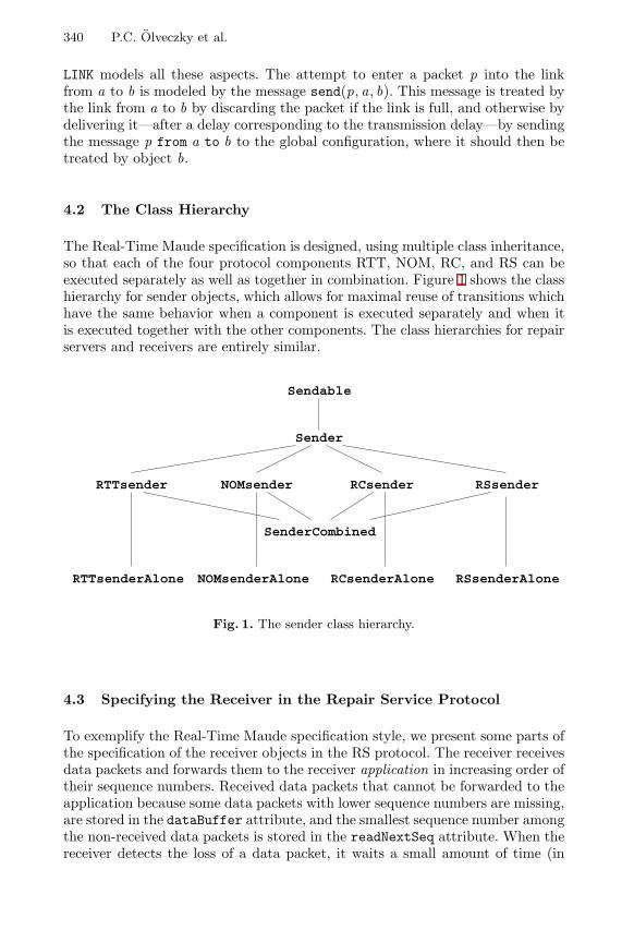
340 P.C. Olveczky et al.
LINK models all these aspects. The attempt to enter a packet p into the linkfrom a to b is modeled by the message send(p, a, b). This message is treated bythe link from a to b by discarding the packet if the link is full, and otherwise bydelivering it—after a delay corresponding to the transmission delay—by sendingthe message p from a to b to the global configuration, where it should then betreated by object b.
4.2 The Class Hierarchy
The Real-Time Maude specification is designed, using multiple class inheritance,so that each of the four protocol components RTT, NOM, RC, and RS can beexecuted separately as well as together in combination. Figure 1 shows the classhierarchy for sender objects, which allows for maximal reuse of transitions whichhave the same behavior when a component is executed separately and when itis executed together with the other components. The class hierarchies for repairservers and receivers are entirely similar.
Sendable
Sender
RTTsender NOMsender RCsender RSsender
RTTsenderAlone NOMsenderAlone RCsenderAlone RSsenderAlone
SenderCombined
Fig. 1. The sender class hierarchy.
4.3 Specifying the Receiver in the Repair Service Protocol
To exemplify the Real-Time Maude specification style, we present some parts ofthe specification of the receiver objects in the RS protocol. The receiver receivesdata packets and forwards them to the receiver application in increasing order oftheir sequence numbers. Received data packets that cannot be forwarded to theapplication because some data packets with lower sequence numbers are missing,are stored in the dataBuffer attribute, and the smallest sequence number amongthe non-received data packets is stored in the readNextSeq attribute. When thereceiver detects the loss of a data packet, it waits a small amount of time (in
The AER/NCA Active Network Protocol Suite in Real-Time Maude 341
case some of its “siblings” or its repair server also have detected the loss) beforesending a NAK-request for the lost packet to its repair server. The repair serverthen either subcasts the data packet from its cache or forwards the requestupstream. The receiver retransmits its request for the missing data packet if itdoes not receive a response to the repair request within a reasonable amount oftime.
We store, for each missing data packet, the information about the recovery at-tempts for the missing data packets in a term
info(seqNo, supprTimer , retransTimer ,NAKcount),
where seqNo is the sequence number of the data packet, supprTimer is thevalue of the suppression timer for the data packet (this value is either the valuenoTimeValue when the timer is turned off, or the time remaining until the timerexpires), retransTimer is the value of the retransmission timer of the data packet,and NAKcount is the NAK count of the data packet, denoting how many timesa repair for the data packet has been attempted. Elements of a sort DataInfoare multisets of info terms, where multiset union is denoted by an associativeand commutative juxtaposition operator.
The receiver class in the RS component is declared as follows:
class RSreceiver |fastRepairFlag : Bool,readNextSeq : NzNat, *** first missing data packetretransTO : Time, *** time before resending NAK packetdataBuffer : MsgConf, *** buffered dataPackets...dataInfo : DataInfo . *** store info about repairs
subclass RSreceiver < Receiver .
class RSreceiverAlone . subclass RSreceiverAlone < RSreceiver .
As an example of the modeling of the use cases in the informal specification,we show the use case and corresponding rule that describes what happens whenthe suppression timer for a missing data packet expires. That is, when the sec-ond parameter of an info-term is 0. The use case in the informal AER/NCAspecification is given as follows:
B.5 This use case begins when the NAK suppression timer for a missingdata packet expires. The following processing is performed (seqis the sequence number of the missing data packet):
if ((data packet seq is currently buffered) OR (seq < readNextSeq)){ End Use Case }if (NAK count for data packet seq > 48){ Error, connection is broken, cannot continue }Unicast a NAK packet for data packet seq with the receiver’s NAK
count and fastRepairFlag to repairServerStart a NAK retransmission timer for data packet seq with a
duration of retransTO
342 P.C. Olveczky et al.
This use case is modeled in Real-Time Maude as follows:
vars Q Q’ : Oid . vars NZN NZN’ : NzNat . var X : Bool .var MC : MsgConf . vars DI DI’ : DataInfo . var N : Nat .var DT : DefTime . var CF : Configuration . var R : Time .op ERROR : -> Configuration .
rl [B5] :{< Q : RSreceiver | readNextSeq : NZN, fastRepairFlag : X,
dataBuffer : MC, repairserver : Q’, retransTO : R,dataInfo : (info(NZN’, 0, DT, N) DI) > CF }
=>{if (NZN’ seqNoIn MC) or (NZN’ < NZN) then(< Q : RSreceiver | dataInfo : (info(NZN’, noTimeValue, DT, N) DI) > CF)else (if 48 < N then ERROR
else (< Q : RSreceiver | dataInfo :(info(NZN’, noTimeValue, R, N) DI) >
send(NAKPacket(NZN’, N, X), Q, Q’) CF) fi) fi} .
The functions mte and delta define the “timed” behavior of receiver objectsof class RSreceiverAlone as follows. The only time-dependent values are thetwo timers in the information state for each missing data packet. The functionmte ensures that the tick rule in Section 2.4 stops the time advance when atimer expires, and the function delta updates the timers according to the timeelapsed:
eq mte(< Q : RSreceiverAlone | dataInfo : DI >) = mte(DI) .op mte : DataInfo -> TimeInf .eq mte((none).DataInfo) = INF .ceq mte(DI DI’) = min(mte(DI), mte(DI’)) if DI =/= none and DI’ =/= none .eq mte(info(NZN, DT, DT’, N)) =
min(if DT =/= noTimeValue then DT else INF fi,if DT’ =/= noTimeValue then DT’ else INF fi) .
eq delta(< Q : RSreceiverAlone | dataInfo : DI >, R) =< Q : RSreceiverAlone | dataInfo : delta(DI, R) > .
op delta : DataInfo Time -> DataInfo ....
5 Formal Analysis of the AER/NCA Protocol Suite inReal-Time Maude
This section illustrates how the AER/NCA protocol has been subjected to rapidprototyping and formal analysis. The analysis is described in full detail in [12].
5.1 Rapid Prototyping
To execute the repair service protocol we added a sender application object anda number of receiver application objects, and defined an initial state RSstate.The sender was supposed to use the protocol to multicast 21 data packets tothe receiver applications. Rewriting this initial state should have led to a statewhere all receiver applications had received all packets. Instead, the executiongave the following result:Maude> (rew- [3000] RSstate .)
result ClockedSystem : {ERROR} in time 17841
The AER/NCA Active Network Protocol Suite in Real-Time Maude 343
By executing fewer rewrites we could follow the execution leading to the ERROR-state, and could easily find the errors in the formal and informal specifications.Executing the repair service protocol with a different initial state revealed an-other undesirable behavior where a lost packet was never repaired, and we couldagain easily trace the error.
The other protocol components, as well as the composite protocol, have beenprototyped by executing initial states, with the desired results:
– Prototyping the RTT protocol resulted in states having the expected valuesof the round trip times the protocol was supposed to find.
– The NOM protocol was prototyped by placing in the environment object(which defines the interface to the other components when a component isexecuted and analyzed separately) the set of data packets which would bereceived by the receivers. That way, we knew which object should be thenominee receiver at any time, and executing the protocol indeed producedstates having the expected nominees.
– The rate control protocol was prototyped by attempting to send a new datapacket every millisecond, and by recording in the state the time stamp ofeach new data packet sent. The list of sending times could then be inspectedto get a feeling for the sending rate, which, as expected, grew (seemingly)exponentially in the beginning.
– The composite protocol was executed with the initial state having the sametopology as the one for which execution of the stand-alone RS protocol failed.However, the composite protocol managed to deliver all data packets to eachreceiver. This was due to the presence of the rate control component, thatadjusted the sending rate to avoid the packet losses which led to the faultybehavior in the execution of the RS protocol component.
5.2 Formal Analysis
To substantially increase our confidence in the specifications before costly at-tempts at formal proofs of correctness, the specifications can be subjected tofurther formal analysis using the search and model checking commands and themeta-programming features of Real-Time Maude.
For example, the RTT protocol should find in the sourceRTT attribute the roundtrip times from each node to the sender. Likewise, each receiver or repair servershould have a maxUpRTT value equal to the maximal round trip time from anyof its “siblings” to its immediate upstream node. As already mentioned, exe-cuting some initial states using Real-Time Maude’s default interpreter indeedresulted in states with the expected values of these attributes. To gain furtherassurance about the correctness of the specification, we have explored not justone behavior, arbitrarily chosen by Real-Time Maude’s default interpreter, butall possible behaviors—relative to certain conditions—starting from the initialstate. The main property the stand-alone RTT protocol should satisfy is that,as long as at most one packet travels in the same direction in the same link atthe same time, the following properties hold:
344 P.C. Olveczky et al.
– each rewrite path will reach a state with the desired sourceRTT andmaxUpRTT values within given time and depth limits (reachability); and
– once these desired values have been found, they will not change within thegiven time limit (stability).
We defined an initial test configuration RTTstate with nodes ’a, ’b, . . . , ’g,and where, in otherwise empty links, the round trip times to the source fromthe nodes ’c, ’d, and ’e are, respectively, 58, 106, and 94, and the maxUpRTTvalues of these nodes are, respectively, 58, 48, and 48. In a module varRTTwhich extends the specification of the RTT protocol with the declaration of thevariables ATTS1, ATTS2, and ATTS3 of the sort AttributeSet of sets of objectattributes, the following pattern is matched by all states where the nodes ’c,’d, and ’e have the above sourceRTT and maxUpRTT values:
{< ’c : RTTrepairserverAlone | sourceRTT : 58, maxUpRTT : 58, ATTS1 >< ’d : RTTrepairserverAlone | sourceRTT : 106, maxUpRTT : 48, ATTS2 >< ’e : RTTreceiverAlone | sourceRTT : 94, maxUpRTT : 48, ATTS3 > CF}.
The desired property that the RTT protocol should satisfy can therefore be givenby the following temporal formula, where P abbreviates the above pattern:
anyPattern UStable≤timeLimit P .
Although this property can be model checked by giving a Real-Time Maudecommand, the tool executes the command too slowly, because it is too generaland performs tests which are not necessary in our specification. Instead, wecan reuse Real-Time Maude’s strategy library to easily define a model checkingfunction ustable in a module extending the module TIMED-META-LEVEL, where
ustable(mod , t0,n, timeLimit , pattern)
gives the set of terms representing rewrite paths using the module mod , startingfrom the initial term t0, which invalidate the reachability-and-stability propertyanyPattern UStable≤timeLimit pattern, and which have maximal bound n onthe number of rewrites in the path (with 0 meaning unbounded). To furtherenhance efficiency, ustable does not return all “bad” states, but only the firststate(s) found which invalidate the property. The search returns emptyTermSetif the property holds for all paths satisfying the given length bound.
Using Full Maude’s up function to get the meta-representation of a term, we cancheck whether the above desired property holds in all rewrite paths having totaltime elapse less than or equal to 400, starting from state RTTstate:
Maude> (red ustable(varRTT, up(varRTT, RTTstate), 0, {’400}’Nat,up(varRTT,
{< ’c : RTTrepairserverAlone | sourceRTT : 58, maxUpRTT : 58, ATTS1 >< ’d : RTTrepairserverAlone | sourceRTT : 106, maxUpRTT : 48, ATTS2 >< ’e : RTTreceiverAlone | sourceRTT : 94, maxUpRTT : 48, ATTS3 > CF})) .)
...result TermSet : emptyTermSet
The AER/NCA Active Network Protocol Suite in Real-Time Maude 345
No path not satisfying the desired property was found, increasing our confidencein the correctness of the protocol. To gain further assurance, we could analyzeexecutions starting with other states.
The search function ustable has also been used to show the undesired prop-erty that there is a behavior—after some receiver has been nominated and isaware of it—in which no receiver has its isNominee flag set to true. This prop-erty can be shown by finding a counterexample to the opposite claim, namelyanyPattern UStable≤∞ P ′, where P ′ is a pattern stating that some receiverhas its isNominee flag set to true. In the module varNOM, which extends theNOM protocol with a declaration of a variable ATTS1 of sort AttributeSet, thepattern {< Q : NOMreceiverAlone | isNominee : true, ATTS1 > CF} is thedesired pattern P ′, which is matched by receivers whose nominee flag is set totrue. The property anyPattern UStable≤∞ P ′ does not hold, and is refuted byproviding a counterexample:
Maude> (down varNOM : red ustable(varNOM, up(varNOM, NOMstate), 0, noTerm,up(varNOM, {< Q : NOMreceiverAlone | isNominee : true, ATTS1 > CF})) .)
result ClockedSystem :{< ’e : NOMreceiverAlone | isNominee : false, ... >< ’a : NOMsenderAlone | csmNominee : ’e, ... >< ’b : NOMreceiverAlone | isNominee : false, ... >< ’f : NOMreceiverAlone | isNominee : false, ... >< ’g : NOMreceiverAlone | isNominee : false, ... >(NAMPacket(true) from ’a to ’e) ... } in time 19504
The NOM protocol has been subjected to further analysis where we have modelchecked the liveness property that a nominee receiver is always found within acertain amount of time.
6 Conclusions
The work presented in this paper has tested the Real-Time Maude tool andMaude formal methodology with a challenging distributed real-time application,uncovering subtle and important errors in the informal specification. Two keyissues for adequate formalization and analysis are the appropriateness and use-fulness of the resulting specification, and the adequacy of the tool support. Inparticular, the formalization needs to be at the right level of abstraction torepresent the essential features—including in this case resource contention andreal-time behavior—without being overwhelmed by the complex nature of thesystem being modeled. In this regard, the modularity and composability of thespecifications for each component made it easy to understand and analyze indi-vidual component and aggregate system behaviors. Furthermore, the flexibilityand extensibility of the Real-Time Maude strategy library made it easy to carryout complex analyses tailored to the specific application that would have beeninfeasible using general purpose algorithms.
There are a number of interesting directions for future work. One is further exten-sions and optimizations of the Real-Time Maude tool. Another direction involves
346 P.C. Olveczky et al.
developing module calculi suitable for composition of protocol components, pro-viding additional composition mechanisms beyond multiple inheritance. A thirdresearch direction is providing additional analytical capabilities, including ab-straction transformations that can map some problems into decidable problems,and proof techniques for reasoning about an even richer class of properties.
Acknowledgments. The authors would like to thank S. Bhattacharyya forhis help in the initial stages of designing the Maude specification, and NarcisoMartı-Oliet for his comments on earlier versions of this paper. This work hasbeen supported by DARPA through Rome Labs. Contract F30602-97-C-0312,by ONR Contract N00014-99-C-0198, and by NSF grants CCR-9900334 andCCR-9900326.
References
1. Active error recovery (AER): AER/NCA software release version 1.1.http://www.tascnets.com/panama/AER/, May 2000.
2. E. Clarke, O. Grumberg, and D. Long. Verification tools for finite-state concurrentsystems. In A Decade of Concurrency - Reflections and Perspectives, volume 803of Lecture Notes in Computer Science. Springer, 1994.
3. M. Clavel, F. Duran, S. Eker, P. Lincoln, N. Martı-Oliet, J. Meseguer, and J. Que-sada. Maude: Specification and Programming in Rewriting Logic. Computer ScienceLaboratory, SRI International, Menlo Park, 1999. http://maude.csl.sri.com.
4. G. Denker, J. Meseguer, and C. L. Talcott. Formal specification and analysis ofactive networks and communication protocols: The Maude experience. In DARPAInformation Survivability Conference and Exposition (DISCEX 2000). IEEE, 2000.
5. F. Duran. A Reflective Module Algebra with Applications to the Maude Language.PhD thesis, University of Malaga, 1999.
6. M. J. C. Gordon and T. F. Melham. Introduction to HOL: A theorem provingenvironment for higher order logic. Cambridge University Press, 1993.
7. G. J. Holzmann. The model checker SPIN. IEEE Trans. on Software Engineering,23(5):279–295, 1997.
8. S. Kasera, S. Bhattacharyya, M. Keaton, D. Kiwior, J. Kurose, D. Towsley, andS. Zabele. Scalable fair reliable multicast using active services. Technical ReportTR 99-44, University of Massachusetts, Amherst, CMPSCI, 1999.
9. K. G. Larsen, P. Pettersson, and W. Yi. Uppaal in a nutshell. Software Tools forTechnology Transfer, 1(1–2):134–152, October 1997. See also Uppaal home-pageat http://www.uppaal.com/.
10. J. Meseguer. Conditional rewriting logic as a unified model of concurrency. Theo-retical Computer Science, 96:73–155, 1992.
11. J. Meseguer. Rewriting logic and Maude: a wide-spectrum semantic framework forobject-based distributed systems. In S. Smith and C.L. Talcott, editors, FormalMethods for Open Object-based Distributed Systems, FMOODS 2000, pages 89–117.Kluwer, 2000.
12. P. C. Olveczky. Specification and Analysis of Real-Time and Hybrid Systems inRewriting Logic. PhD thesis, University of Bergen, 2000. Available athttp://maude.csl.sri.com/papers.

The AER/NCA Active Network Protocol Suite in Real-Time Maude 347
13. P. C. Olveczky. Specifying and analyzing the AER/NCA active network protocolsin Real-Time Maude. http://www.csl.sri.com/˜peter/AER/AER.html, 2000.
14. P. C. Olveczky and J. Meseguer. Real-Time Maude: A tool for simulating and an-alyzing real-time and hybrid systems. In Third International Workshop on Rewrit-ing Logic and its Applications, 2000. To appear in Electronic Notes in TheoreticalComputer Science.
15. P. C. Olveczky and J. Meseguer. Specification of real-time and hybrid systems inrewriting logic. To appear in Theoretical Computer Science. Available athttp://maude.csl.sri.com/papers, September 2000.
16. S. Owre, J. Rushby, and N. Shankar. PVS: A prototype verification system. InAutomated Deduction–CADE-11, volume 607 of Lecture Notes in Artificial Intelli-gence, pages 748–752, 1992.
17. L. C. Paulson. Isabelle, volume 828 of Lecture Notes in Computer Science. SpringerVerlag, 1994.
18. S. Yovine. Kronos: A verification tool for real-time systems. Software Tools forTechnology Transfer, 1(1/2), 1997. See also Kronos home-page athttp://www-verimag.imag.fr/TEMPORISE/kronos/.

Author Index
Astesiano, Egidio 171Autexier, Serge 269
Bordleau, Francis 156Browne, James C. 318Brune, Georg 233
Cerioli, Maura 171Choppy, Christine 124Clark, Tony 17Corriveau, Jean-Pierre 156
Ehrich, Hans-Dieter 32Erochok, Andrei 249Eshuis, Rik 76Evans, Andy 17
Fischer, Clemens 91
Goerigk, Werner 249
Hagerer, Andreas 233, 249Hammelmann, Bernhard 249Heckel, Reiko 109Hennicker, Rolf 300Hoffman, Piotr 253Horwitz, Susan 217Hutter, Dieter 269
Ide, Hans-Dieter 233Inverardi, Paola 60
Jacobs, Bart 284Jurjens, Jan 187
Keaton, Mark 333Kent, Stuart 17Klin, Bartek 253Kolodziejczyk-Strunck, Klaus 249Kurshan, Robert P. 318
Lammel, Ralf 201Loginov, Alexey 217
Margaria, Tiziana 233Meseguer, Jose 333Mossakowski, Till 253, 269
Nagelmann, Markus 249Niese, Oliver 233, 249
Olveczky, Peter C. 333Olderog, Ernst-Rudiger 91Ostroff, Jonathan S. 2
Paige, Richard F. 2Pinger, Ralf 32Poizat, Pascal 124Poll, Erik 284
Reed, Joy N. 45Reggio, Gianna 171Reps, Thomas 217Reus, Bernhard 300Royer, Jean-Claude 124
Sauer, Stefan 109Schroder, Lutz 253Selic, Bran 1Sharygina, Natasha 318Sinclair, Jane E. 45Steffen, Bernhard 233Stevens, Perdita 140
Talcott, Carolyn 333Tarlecki, Andrzej 253
Uchitel, Sebastian 60
Wehrheim, Heike 91Wieringa, Roel 76Wirsing, Martin 300
Yong, Suan Hsi 217
Zabele, Steve 333