Embed Size (px)
Citation preview

8/3/2019 Lecture No.8
http://slidepdf.com/reader/full/lecture-no8 1/49
8/3/2019 Lecture No.8
http://slidepdf.com/reader/full/lecture-no8 2/49

8/3/2019 Lecture No.8
http://slidepdf.com/reader/full/lecture-no8 3/49
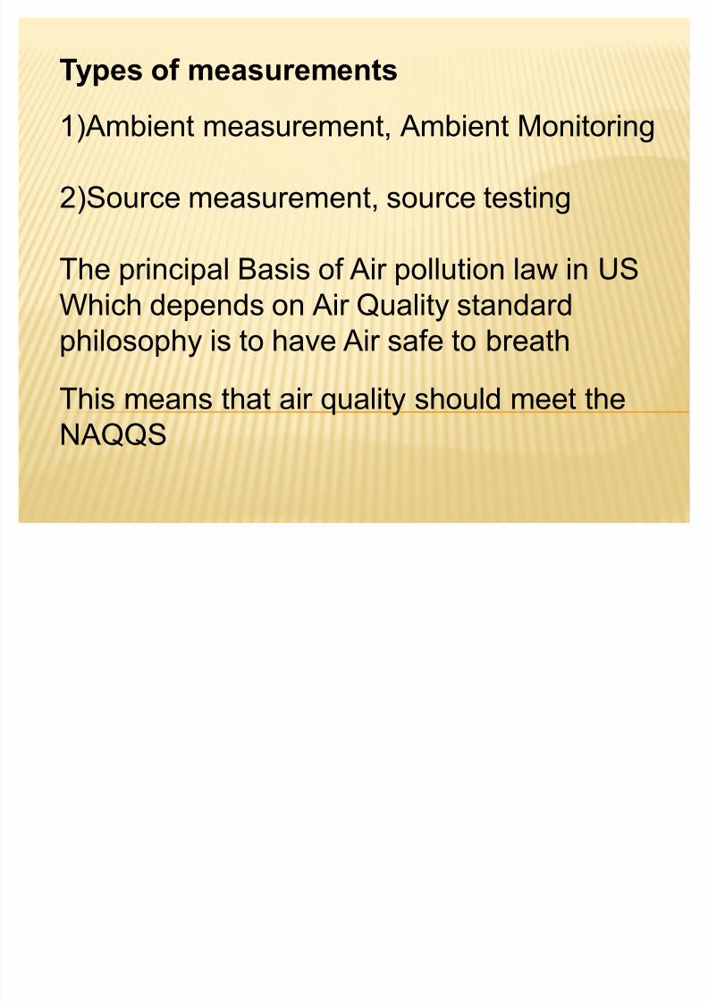
To achieve that :
Control and Monitoring of Air pollutants should
be implemented
To control pollutant concentrationsThe time, the place, and the amount of
emissions, should be regulated
Hence, The emission rates of various sources
of air pollutants«.must be regulated and
measured

8/3/2019 Lecture No.8
http://slidepdf.com/reader/full/lecture-no8 4/49
Why measurements are needed?
1) Legal Requirements
2) Evaluation of air pollution control devices
N ote: The control devices should be bought with Guarantee,
and final payments should be after, demonstration that the
device is installed ,calibrated and in good performance
situation.

8/3/2019 Lecture No.8
http://slidepdf.com/reader/full/lecture-no8 5/49
In most air pollution control agencies the
monitoring and source testing are done bydifferent people, Whose different terminologies
But all Air pollution measuring devices
(ambient or source) have some or all of thevarious parts shown in the figure 4.1.
WHAT IS THE AIM OF SAMPLING ?

8/3/2019 Lecture No.8
http://slidepdf.com/reader/full/lecture-no8 6/49

8/3/2019 Lecture No.8
http://slidepdf.com/reader/full/lecture-no8 7/49
The major components of most sampling
systems are
1) An inlet manifold
2) An Air mover
3) A collection medium
4 ) Flow measurement device

8/3/2019 Lecture No.8
http://slidepdf.com/reader/full/lecture-no8 8/49
(1) The inlet manifold transports the material from the
ambient atmosphere to the collection medium or
analytical device in an unaltered condition, all inlet of
ambient air must be rainproof
(2) The air mover provides the force to create a
vacuum or lower pressure at the end of the sampling
system (pumps)
(3) The collecting medium, may be solid or liquid
sorbent for dissolving gases a filter surface for
collecting particles or a chamber to contain an aliquotof air for analysis
(4)The flow device measures the volume of air
associated with the sampling system

8/3/2019 Lecture No.8
http://slidepdf.com/reader/full/lecture-no8 9/49

8/3/2019 Lecture No.8
http://slidepdf.com/reader/full/lecture-no8 10/49
A Representative sample
In Air measurements there are two importantproblems
1)To obtain the suitable representative sample
2)The determination of the concentration of the
pollutant of interest in it correctly
which is harder 1-or-2?
The representative ambient air sample hasbeen the topic of legal and technical
controversy
H ow?

8/3/2019 Lecture No.8
http://slidepdf.com/reader/full/lecture-no8 11/49
(1) The air inside the parking structure normally
contains much more CO than the NAQQS
(2) If the sample was taken from inside the parkingstructure, the result will show grate violation of
NAAQS
(3) If the sample is taken directly across the street
from such a structure, in a most cases theconcentration will be an order of magnitude less than
inside the structure
(4) A block away, the concentration will be even less
(5) On the side walk directly adjacent to the structure,the concentration will be may twice as high as on the
opposite side of the street.

8/3/2019 Lecture No.8
http://slidepdf.com/reader/full/lecture-no8 12/49

8/3/2019 Lecture No.8
http://slidepdf.com/reader/full/lecture-no8 13/49
Which of these locations is suitable for
obtaining a sample of ambient air?
Generally the ambient air sampler should be
located at the place to which the public has
free access where the pollutant concentrationis highest
This means that all indoor spaces, which thepublic has no access are excluded

8/3/2019 Lecture No.8
http://slidepdf.com/reader/full/lecture-no8 14/49
Where we can put an ambient air monitor ?
In Place:
1- has the power
2- shelter from rain and snow3- constant temp. and pressure
4- easy access from monitoring personnel
5- protection from vandalism
6- if possible free rent place

8/3/2019 Lecture No.8
http://slidepdf.com/reader/full/lecture-no8 15/49
In the previous case, the suitable place is theroof of county health building or of the county
courthouse. However the concentration of theouter-related pollutants measured there ismuch lower than at street levels at the busiest
intersection downtown.There are EPA guidelines for the properplacement of intake of air samples that are to
represent ambient air.i.e. CO measurements must be made at street level, downtown.
or in the same manner

8/3/2019 Lecture No.8
http://slidepdf.com/reader/full/lecture-no8 16/49
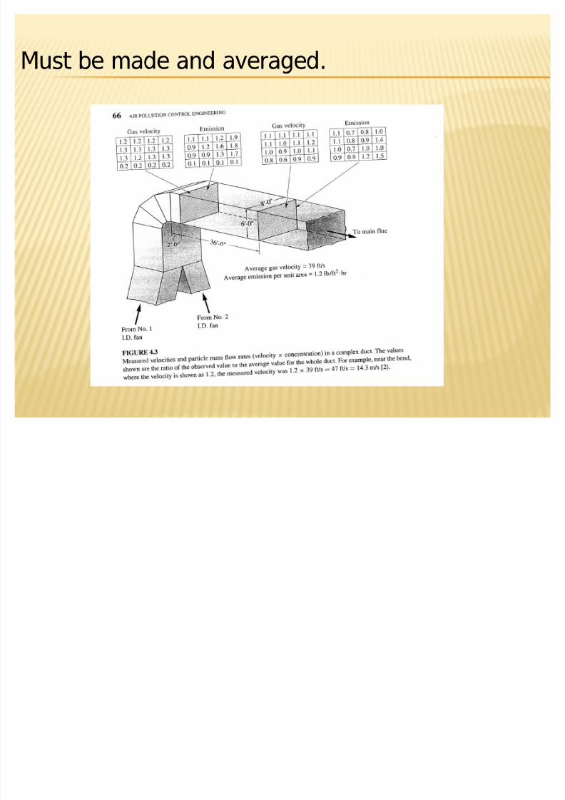
In source testing:
The representative sample problem is equallydifficult
1- if the gas flow in large industrial smokestack
is steady, well mixed across the diameter of thestack. It can be taken a representative sampleany time and at any place.
2- most of such stacks have variation invelocities and concentrations from point topoint, and from time to time.
In this case, many separate measurements
8/3/2019 Lecture No.8
http://slidepdf.com/reader/full/lecture-no8 17/49
Must be made and averaged.

8/3/2019 Lecture No.8
http://slidepdf.com/reader/full/lecture-no8 18/49

8/3/2019 Lecture No.8
http://slidepdf.com/reader/full/lecture-no8 19/49
Presumably, if one can went for enough
down stream in this duct, one would findthat the flow velocities and particleconcentrations had become uniform. If onecould do that,
He should do that.
But more typical sampling situation is shown
in figure 4.4. In such ducts, one cannot finda place from downstream from any changeof direction or other flow disturbance.

8/3/2019 Lecture No.8
http://slidepdf.com/reader/full/lecture-no8 20/49
In newer plants, designers have sometimesconsidered the problems of obtaining a
uniform gas flow and have provided accessand a suitable location for the sourcesampler to place the required instruments.

8/3/2019 Lecture No.8
http://slidepdf.com/reader/full/lecture-no8 21/49

8/3/2019 Lecture No.8
http://slidepdf.com/reader/full/lecture-no8 22/49
4.2: Getting the representative sample to
the detector-Many sampling instruments have some kind
device on the inlet to exclude unwanted
materials. i.e.- Insects sucked into a particulate samplernozzle lead to erroneously high readings
- Dust particles of less health concern that weigh more than all of the fine particles in thesame air sample, which is of serious health
concern.

8/3/2019 Lecture No.8
http://slidepdf.com/reader/full/lecture-no8 23/49
Consistency between inlet excludingmaterials and modification of analysis.
i.e. in table 2.3, EPA modified its particulatesamplers in 1987 and in 1997.
Before 1987, the sampler inlet was designed toexclude all particles larger than 50 micron, thequantity sampled was called Total Suspendedparticulate ( TSP).
The 1987 modification changed the inlet toexclude all particles larger than 10 micron, thequantity sampled is called PM10 (particulate matter 10
micron or smaller)

8/3/2019 Lecture No.8
http://slidepdf.com/reader/full/lecture-no8 24/49
The 1997 modification changed the inlet againto exclude all particles larger than 2.5 micron.(PM2.5 or smaller). The 1997 modification alsochanged the flow rate.
-In sampling device, gases may condense inthe sampling device, or react with the solidsencounter there.
-Many combustion stack gases have a highwater content and will condense on the wallsof unheated sampling probe. In such cases,probes are normally heated to prevent this.

8/3/2019 Lecture No.8
http://slidepdf.com/reader/full/lecture-no8 25/49
-Acid gases like SO2 will react with alkalinesolids on a filter, thus increasing the weight of solids on the filter.
-If a grab sample is to be brought to the labfor analysis, the sample container should befrom appropriate material and well pretreatedaccording to the analyte type .
i.e. even glass containers can react with someair pollutants.

8/3/2019 Lecture No.8
http://slidepdf.com/reader/full/lecture-no8 26/49
4.3 Concentration Determination
After sampling representatively and correctly,determination of analyte concentration isfollowed.
For some pollutants, can be measured easilyby real time instruments.
Most of these operate optically, due to
absorbance and transmittance at a particulatewavelength.
i.e. Spectrophotometric methods.

8/3/2019 Lecture No.8
http://slidepdf.com/reader/full/lecture-no8 27/49
The problem of interferences
The interferences problem in air pollutantsmeasurements is not trivial
Even in the spectrophotometric methods, some
interferences gases can be absorbed on thesame wavelength.
i.e.
Measuring SO2 gas in N2 gas is easy, due to thereaction

8/3/2019 Lecture No.8
http://slidepdf.com/reader/full/lecture-no8 28/49
SO2 + 2NaOH Na2SO3 + H2O
And measuring the change in NaOHconcentration by simple acid base titration.However, if the problem is to measure SO2 inair, CO2 in the air will also react as the
following reaction:
CO2 + 2NaOH Na2CO3 + H2O
if CO2 concentration in air in this case issteady and known, so a correction could bemade in principle (but not in practice).
But in the other cases, the interfering of the

8/3/2019 Lecture No.8
http://slidepdf.com/reader/full/lecture-no8 29/49
other components may be not known.
i.e. the US EPA adopted a new method formeasuring NO2 and had to withdraw it, whenbecame clear that the method was not adequately protected from such interferences.
4.4: Averaging
Measuring ambient air quality with real time
instruments, generally the averageconcentration over some period of time isgiven, i.e.

8/3/2019 Lecture No.8
http://slidepdf.com/reader/full/lecture-no8 30/49
Average concentration = Cavg= 1/t c.dt
C= the instantaneous concentration
t= the time of measurement
Most of real-time instruments present their
results as an electronic signal that can beeasily averaged by built-in electronics for anysuitable chosen averaging time.
The older instruments for gases as well asthe current instruments, for particulate not real time instruments, but rather are
averaging instruments.

8/3/2019 Lecture No.8
http://slidepdf.com/reader/full/lecture-no8 31/49
For example:
In EPA method for PM2.5 sampling, it consistsof:
- Special inlet that exclude particles >2.5micron in diameter
-A filter
-A fan
-A flow measuring device
-Suitable housing
Collection is for 24 hrs

8/3/2019 Lecture No.8
http://slidepdf.com/reader/full/lecture-no8 32/49
Average Concentration =
increase in filter weight / air flow rate x t
Example 4.2:
In the example 4.2:
-- The sample size is small
-The average value 21 µg/m3 is 84% of the
annual avg NAAQS.-Measured change in filter weight is 0.5 mg.
-high quality weighing and sample humidity
control is needed

8/3/2019 Lecture No.8
http://slidepdf.com/reader/full/lecture-no8 33/49
-The resulting statistical errors percentages,can be high
- The resulting measurements are upon 24hours period, which means that this type of instruments is not suitable for determining
hourly variations or trends as the real timeinstruments.
Efforts to develop a suitable real timeinstruments for PM2.5 have so far not beencompletely successful.

8/3/2019 Lecture No.8
http://slidepdf.com/reader/full/lecture-no8 34/49
Older measuring schemes for gas pollutants
have the principles of:1-Reaction of known solution with the gaseouspollutant itself rather than the interferences
2- titration of the solution to determine theconcentration of the gas
N1 V1 = N2 V2
3- Or measuring the color of the solution,spectrophotometrically.

8/3/2019 Lecture No.8
http://slidepdf.com/reader/full/lecture-no8 35/49
Many source devices use the cumulativemeasuring schemes
For example:
The EPA recommended sampling train formeasuring the concentration of SO2 gas in astack

8/3/2019 Lecture No.8
http://slidepdf.com/reader/full/lecture-no8 36/49

8/3/2019 Lecture No.8
http://slidepdf.com/reader/full/lecture-no8 37/49

8/3/2019 Lecture No.8
http://slidepdf.com/reader/full/lecture-no8 38/49
4.5 Standard Analytical Methods
EPA has standard methods for variouspollutants. (often one for source and other forambient air)
These methods define the pollutant.
i.e.
SO2 is defined as the material which is detectedby the SO2 method shown in EPA STTANDARDMETHODS FOR M AJOR AIR POLLUTANTS IN
AMBIENT AIR (table 4.1)

8/3/2019 Lecture No.8
http://slidepdf.com/reader/full/lecture-no8 39/49
However, in powerplant stack SO2 is defined asthat material that is detected by (Method 6, Fig.4.5) which is chemically quite different from theWest Gaeke method.

8/3/2019 Lecture No.8
http://slidepdf.com/reader/full/lecture-no8 40/49
Test methods for major air pollutants inambient air
Reference methods
Equivalent methods
- TSP, PM10, PM2.5
3 standard methods, differ in the excluding in
the inlet .
Collecting on a filter for 24 hours
Averaging the results (weight difference)
8/3/2019 Lecture No.8
http://slidepdf.com/reader/full/lecture-no8 41/49
-SO2: West-Gaeke Method
Known volume of air bubbled through asolution of sodium tetrachloro mercurate(TCM) formin a complex with SO2.
Then, the solution is treated severaly, endingwith pararosaniline to form intensity coloredpararosaniline methyl sulfonic acid,
The concentration is determined colorimetric,at wavelength 548 nm.
8/3/2019 Lecture No.8
http://slidepdf.com/reader/full/lecture-no8 42/49
-Ozone
(chemioluminscence by etheylene)The air is mixed with ethylene, which reactswith ozone in a light-emitting reaction
(chemioluminscence reaction).
The light is measured with a photomultipliertube related to concentration of the Ozone
reacted.

8/3/2019 Lecture No.8
http://slidepdf.com/reader/full/lecture-no8 43/49
- CO
Nondispersive IR photometry (NDIR) Absorption of IR radiation by CO
Detection due to energy difference signal
Note:
This method is sensitive for water vaporinterferences.

8/3/2019 Lecture No.8
http://slidepdf.com/reader/full/lecture-no8 44/49
-Hydrocarbons (non methane)
Gas is passed through FDI, where HC isburned in a hydrogen flame.
HC cause more ionization than H2 and this
ionization is detected electronically.Part of the sample is diverted fordetermination of direct CH4 by GC.
Note:
HC determination is important even it is not NAAQS, for ozone control program

8/3/2019 Lecture No.8
http://slidepdf.com/reader/full/lecture-no8 45/49
-NO2
NO2 is converted to NONO is reacted with O3 (chemioluminscencereaction).
NO + O3 NO*2 + O2
NO*2 NO2 + h (photons)
In parallel, sample is reacted with O3 to quantify NO in air in order to subtract and find NO2.

8/3/2019 Lecture No.8
http://slidepdf.com/reader/full/lecture-no8 46/49
-Lead
Using TSP filter Analysis in lab using AAS or ICP

8/3/2019 Lecture No.8
http://slidepdf.com/reader/full/lecture-no8 47/49

8/3/2019 Lecture No.8
http://slidepdf.com/reader/full/lecture-no8 48/49

8/3/2019 Lecture No.8
http://slidepdf.com/reader/full/lecture-no8 49/49