Embed Size (px)
Citation preview
Lecture Computer Networks
Ethernet and FDDI
Prof. Dr. Hans Peter Großmann mit M. Rabel sowieH. Hutschenreiter und T. Nau | Sommersemester 2012 |Institut für Organisation und Management von Informationssystemen
Thomas Nau, kiz
Computer Networks | Ethernet and FDDI | Sommersemester 2012Page 2
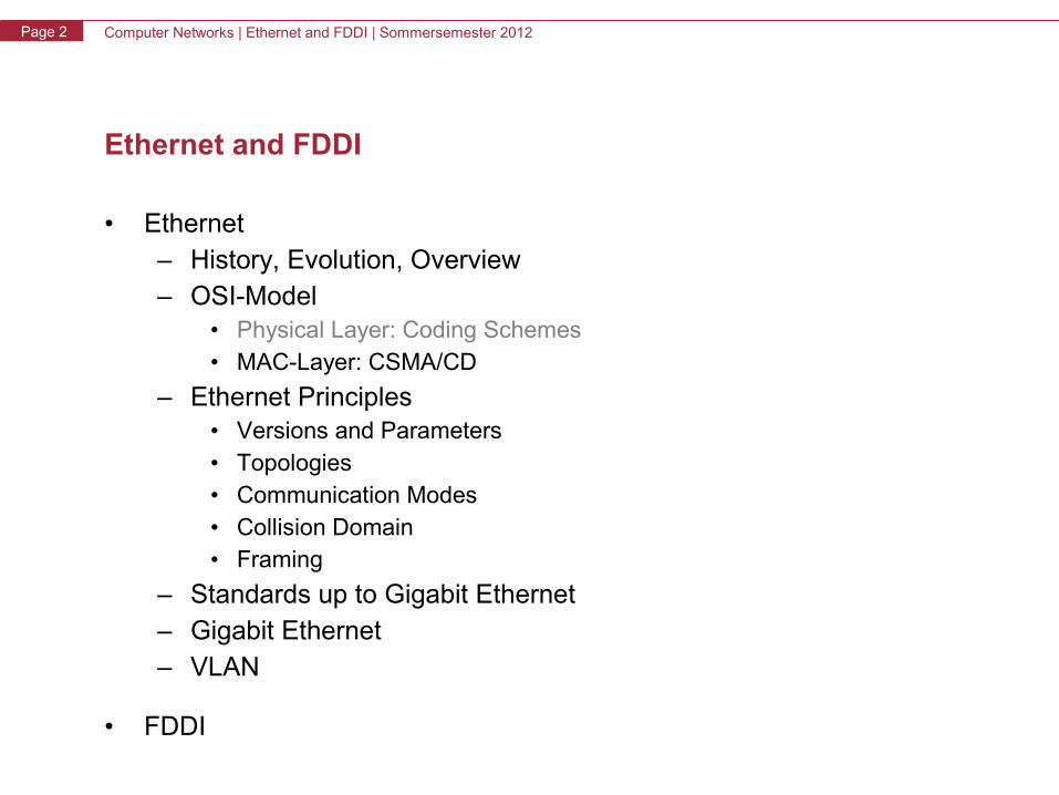
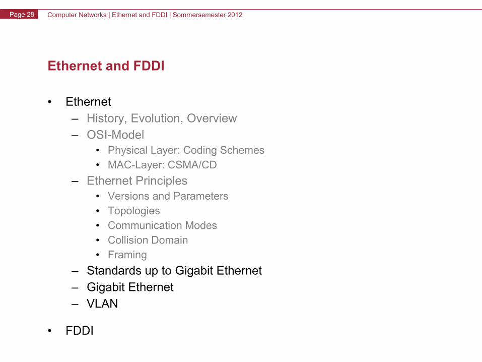
Ethernet and FDDI
• Ethernet– History, Evolution, Overview– OSI-Model
• Physical Layer: Coding Schemes• MAC-Layer: CSMA/CD
– Ethernet Principles• Versions and Parameters• Topologies• Communication Modes• Collision Domain• Framing
– Standards up to Gigabit Ethernet– Gigabit Ethernet– VLAN
• FDDI
Computer Networks | Ethernet and FDDI | Sommersemester 2012Page 3
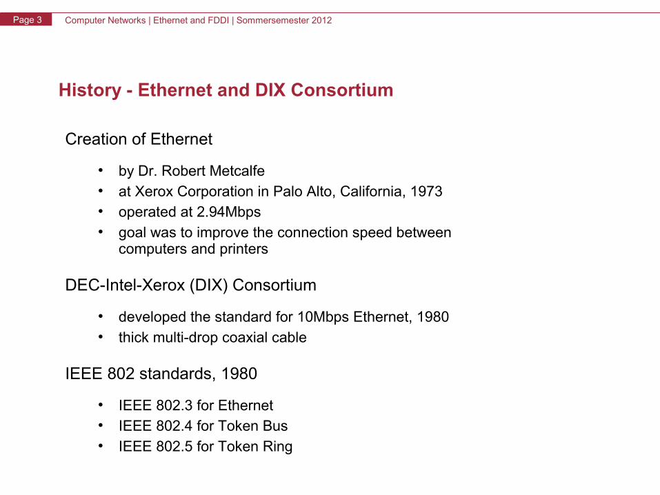
History - Ethernet and DIX Consortium
Creation of Ethernet
• by Dr. Robert Metcalfe• at Xerox Corporation in Palo Alto, California, 1973• operated at 2.94Mbps• goal was to improve the connection speed between
computers and printers
DEC-Intel-Xerox (DIX) Consortium
• developed the standard for 10Mbps Ethernet, 1980• thick multi-drop coaxial cable
IEEE 802 standards, 1980
• IEEE 802.3 for Ethernet• IEEE 802.4 for Token Bus• IEEE 802.5 for Token Ring
Computer Networks | Ethernet and FDDI | Sommersemester 2012Page 4
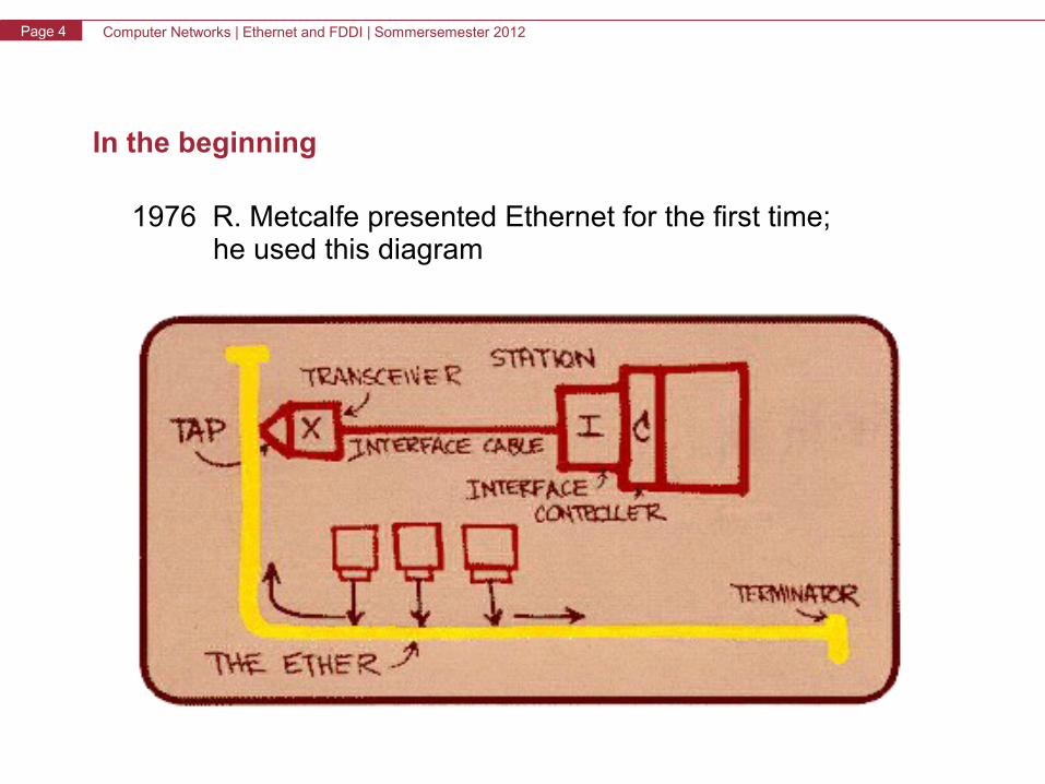
In the beginning
1976 R. Metcalfe presented Ethernet for the first time; he used this diagram
Computer Networks | Ethernet and FDDI | Sommersemester 2012Page 5
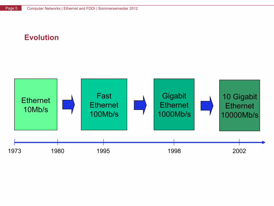
Evolution
Ethernet10Mb/s
FastEthernet100Mb/s
GigabitEthernet
1000Mb/s
1973 1998
10 GigabitEthernet
10000Mb/s
200219951980
Computer Networks | Ethernet and FDDI | Sommersemester 2012Page 6
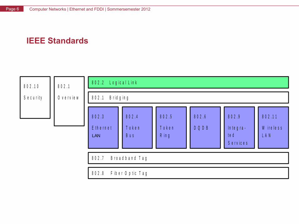
IEEE Standards
8 0 2 . 7 B r o a d b a n d T a g
8 0 2 . 8 F i b e r O p t i c T a g
L A NW i r e l e s s
8 0 2 . 1 18 0 2 . 9
D Q D B
8 0 2 . 6
R i n g
8 0 2 . 48 0 2 . 3
E t h e r n e tLAN B u s
T o k e n
8 0 2 . 1 B r i d g i n g
8 0 2 . 2 L o g i c a l L i n k8 0 2 . 1
S e c u r i t y O v e r v i e w
8 0 2 . 1 0
8 0 2 . 5
T o k e n
S e r v i c e s
I n t e g r a -t e d
Computer Networks | Ethernet and FDDI | Sommersemester 2012Page 7
Ethernet and FDDI
• Ethernet– History, Evolution, Overview– OSI-Model
• Physical Layer: Coding Schemes• MAC-Layer: CSMA/CD
– Ethernet Principles• Versions and Parameters• Topologies• Communication Modes• Collision Domain• Framing
– Standards up to Gigabit Ethernet– Gigabit Ethernet– VLAN
• FDDI
Computer Networks | Ethernet and FDDI | Sommersemester 2012Page 8
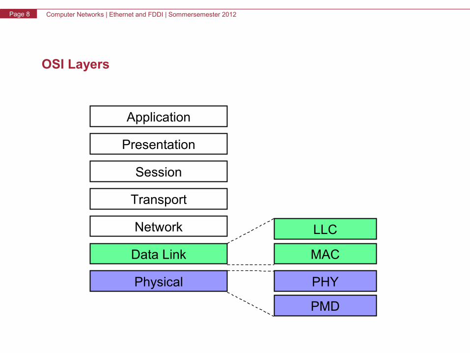
OSI Layers
Application
Presentation
Session
Transport
Data Link
Network
Physical
LLC
MAC
PHY
PMD
Computer Networks | Ethernet and FDDI | Sommersemester 2012Page 9
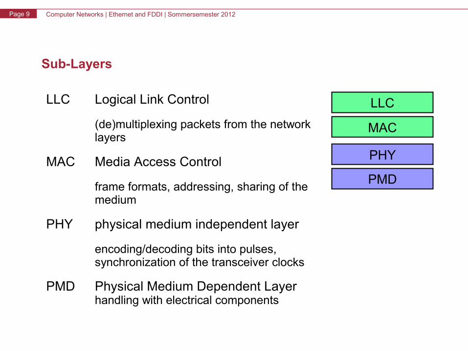
Sub-Layers
LLC Logical Link Control
(de)multiplexing packets from the network layers
MAC Media Access Control
frame formats, addressing, sharing of the medium
PHY physical medium independent layer
encoding/decoding bits into pulses, synchronization of the transceiver clocks
PMD Physical Medium Dependent Layer handling with electrical components
LLC
MAC
PHY
PMD
Computer Networks | Ethernet and FDDI | Sommersemester 2012Page 10
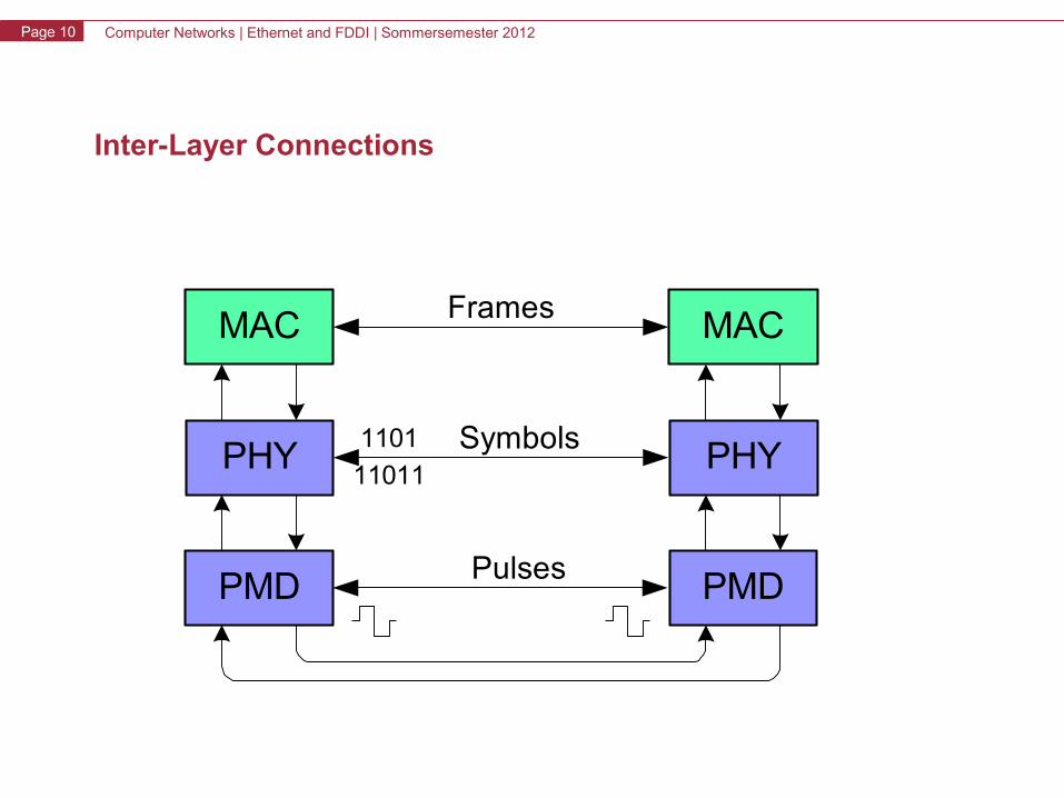
Inter-Layer Connections
MAC
PHY
PMD
MAC
PHY
PMD
Frames
Symbols
Pulses
1101
11011
Computer Networks | Ethernet and FDDI | Sommersemester 2012Page 11
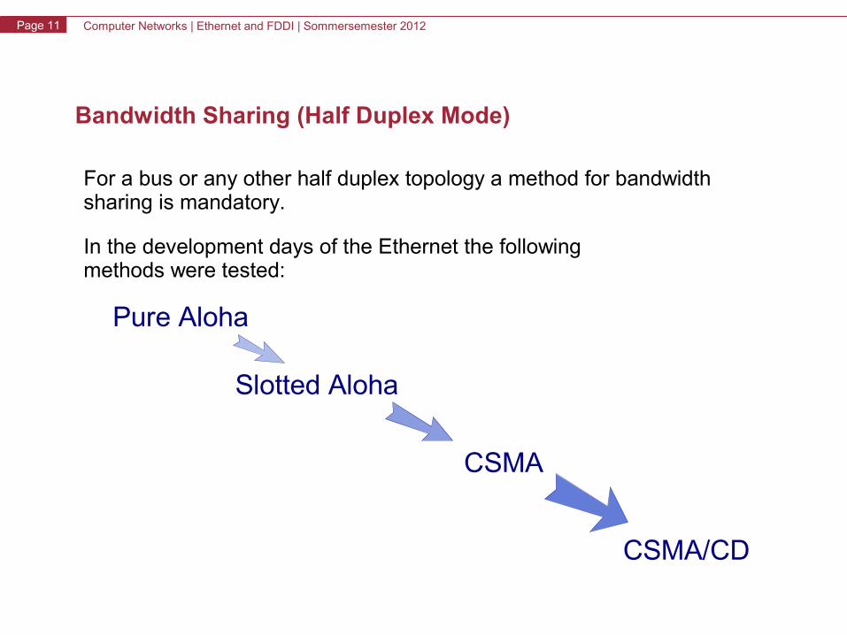
Bandwidth Sharing (Half Duplex Mode)
For a bus or any other half duplex topology a method for bandwidth sharing is mandatory.
In the development days of the Ethernet the followingmethods were tested:
Pure Aloha
Slotted Aloha
CSMA
CSMA/CD
Computer Networks | Ethernet and FDDI | Sommersemester 2012Page 12
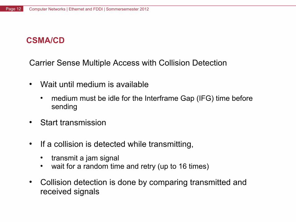
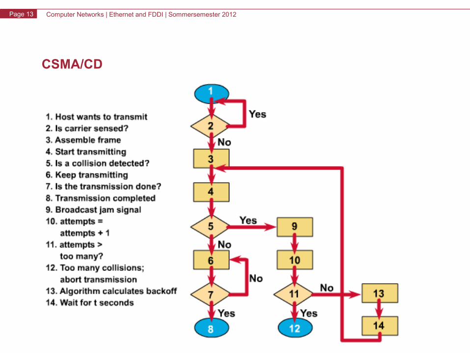
CSMA/CD
Carrier Sense Multiple Access with Collision Detection
• Wait until medium is available
• medium must be idle for the Interframe Gap (IFG) time before sending
• Start transmission
• If a collision is detected while transmitting,
• transmit a jam signal • wait for a random time and retry (up to 16 times)
• Collision detection is done by comparing transmitted and received signals
Computer Networks | Ethernet and FDDI | Sommersemester 2012Page 13
CSMA/CD
Computer Networks | Ethernet and FDDI | Sommersemester 2012Page 14
Ethernet and FDDI
• Ethernet– History, Evolution, Overview– OSI-Model
• Physical Layer: Coding Schemes• MAC-Layer: CSMA/CD
– Ethernet Principles• Versions and Parameters• Topologies• Communication Modes• Collision Domain• Framing
– Standards up to Gigabit Ethernet– Gigabit Ethernet– VLAN
• FDDI
Computer Networks | Ethernet and FDDI | Sommersemester 2012Page 15
Ethernet Versions
Two incompatible versions:
• Ethernet II (DIX - consortium of the companies DEC, Intel and Xerox)
• Ethernet 802.3 (standard of IEEE)
• PMD, PHY, and MAC layers are covered in the standard IEEE 802.3
• LLC - covered in the standard IEEE 802.2 (general standard, not only for Ethernet)
Computer Networks | Ethernet and FDDI | Sommersemester 2012Page 16
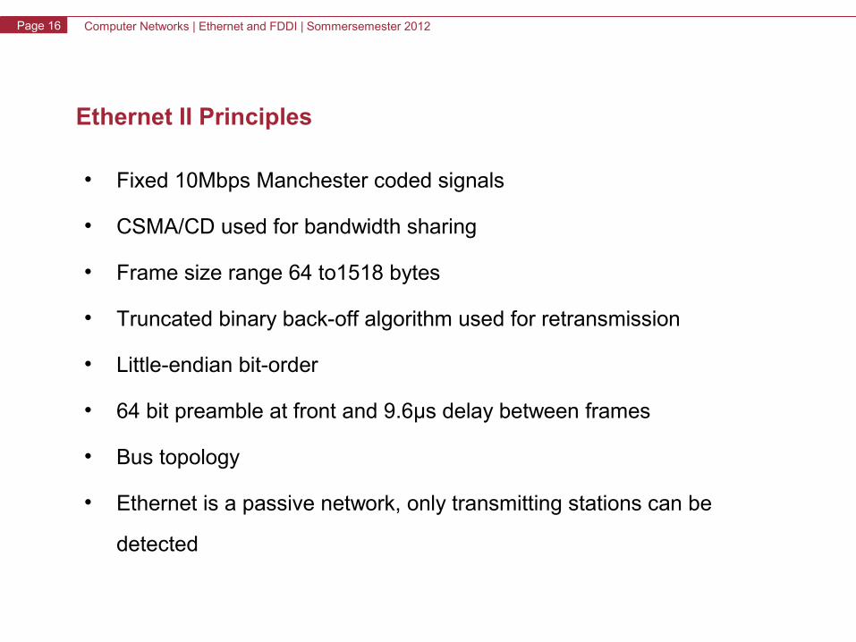
Ethernet II Principles
• Fixed 10Mbps Manchester coded signals
• CSMA/CD used for bandwidth sharing
• Frame size range 64 to1518 bytes
• Truncated binary back-off algorithm used for retransmission
• Little-endian bit-order
• 64 bit preamble at front and 9.6μs delay between frames
• Bus topology
• Ethernet is a passive network, only transmitting stations can be
detected
Computer Networks | Ethernet and FDDI | Sommersemester 2012Page 17
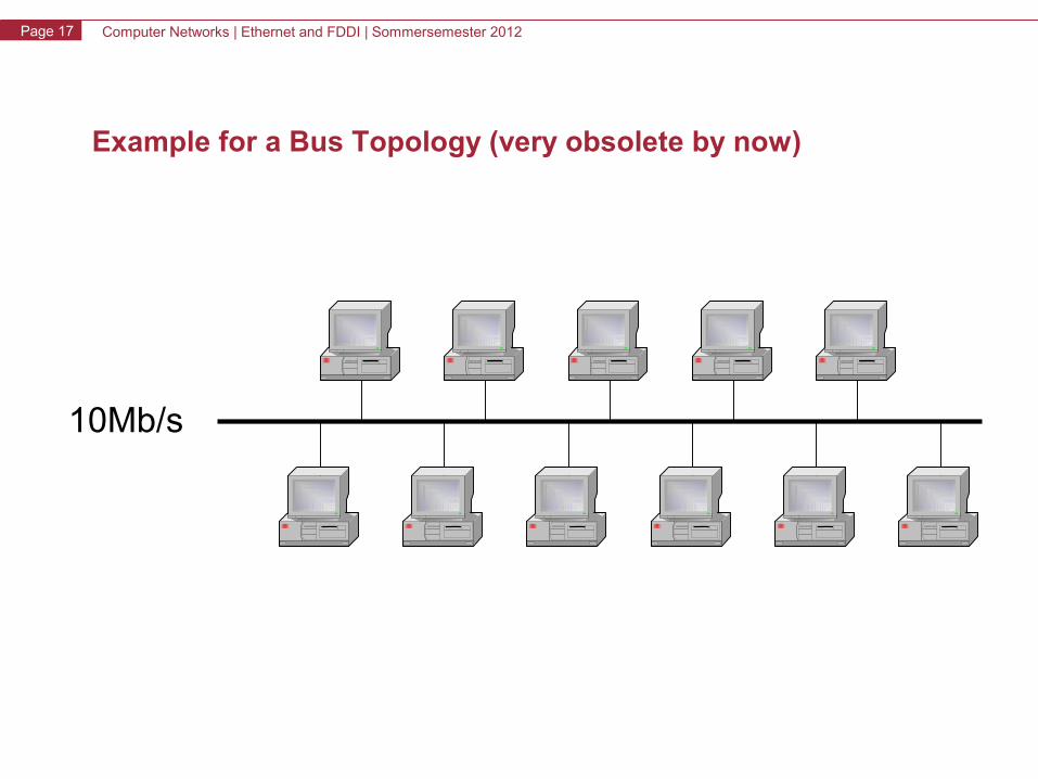
Example for a Bus Topology (very obsolete by now)
10Mb/s
Computer Networks | Ethernet and FDDI | Sommersemester 2012Page 18
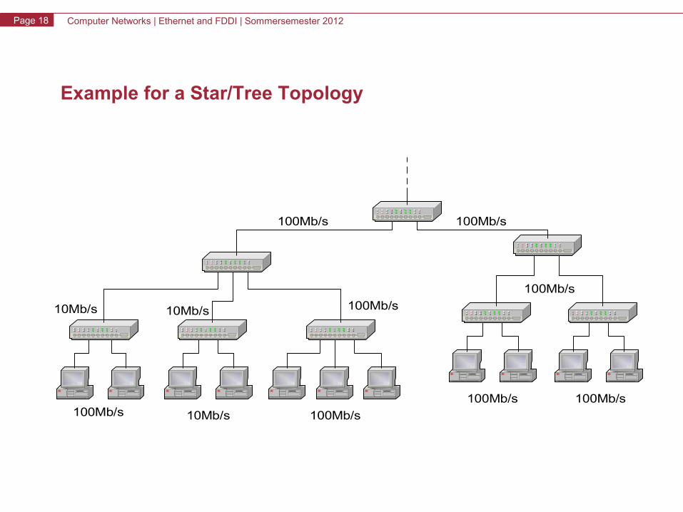
Example for a Star/Tree Topology
100Mb/s 100Mb/s
100Mb/s
100Mb/s 100Mb/s
100Mb/s10Mb/s
100Mb/s 10Mb/s 100Mb/s
10Mb/s
Computer Networks | Ethernet and FDDI | Sommersemester 2012Page 19
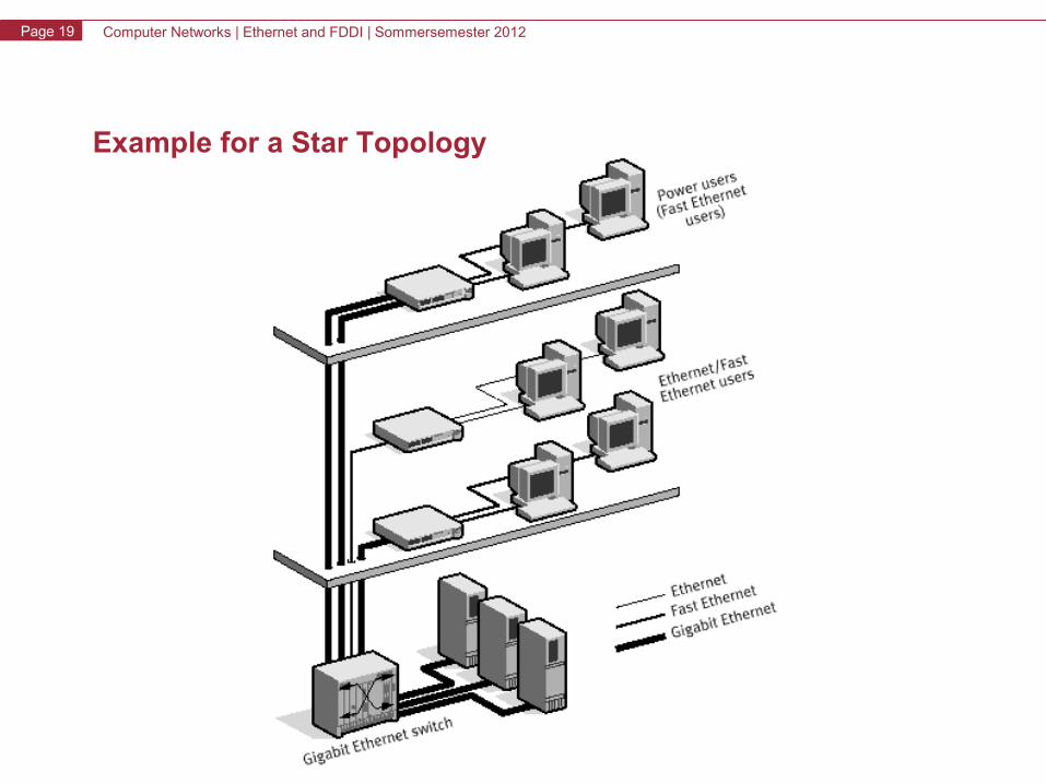
Example for a Star Topology
Computer Networks | Ethernet and FDDI | Sommersemester 2012Page 20
Half-duplex Mode
• Stations share a single Ethernet channel by using a medium access control protocol (see CSMA/CD)
• Only one station can send data over the channel at any given time
• Disadvantage: segment length is limited by timing requirement caused by requirements of collision detection mechanism
Computer Networks | Ethernet and FDDI | Sommersemester 2012Page 21
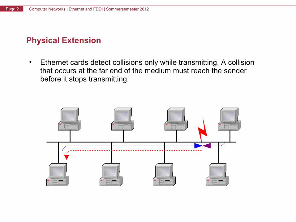
Physical Extension
• Ethernet cards detect collisions only while transmitting. A collision that occurs at the far end of the medium must reach the sender before it stops transmitting.
Computer Networks | Ethernet and FDDI | Sommersemester 2012Page 22
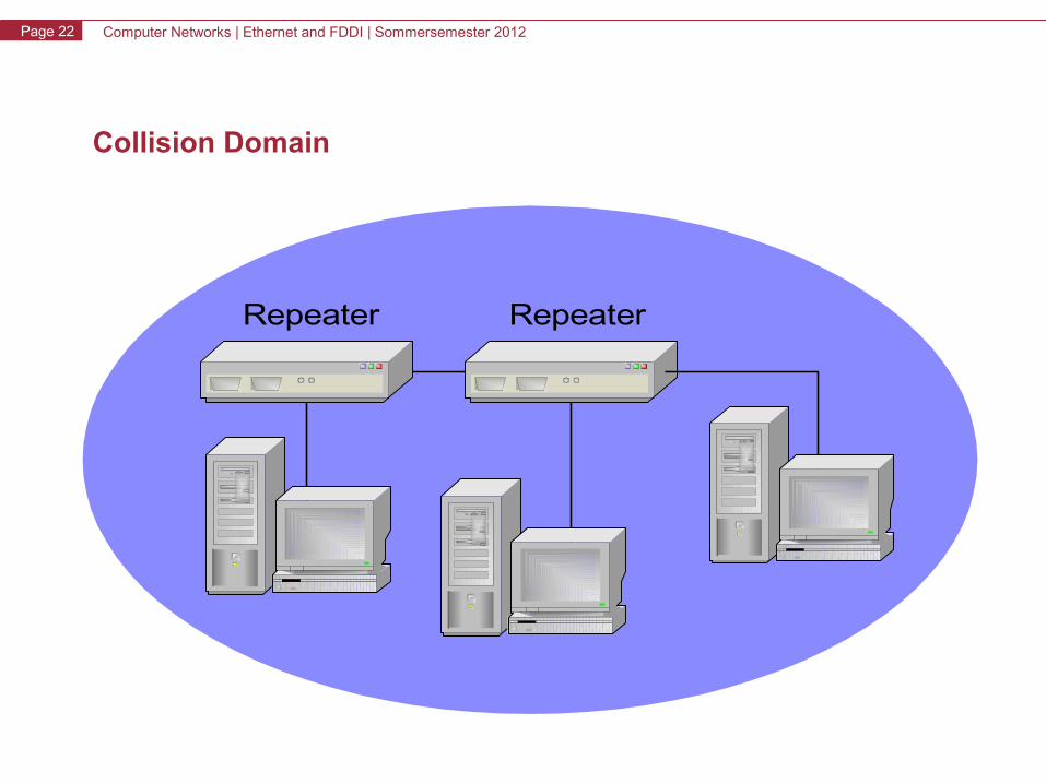
Collision Domain
RepeaterRepeater
Computer Networks | Ethernet and FDDI | Sommersemester 2012Page 23
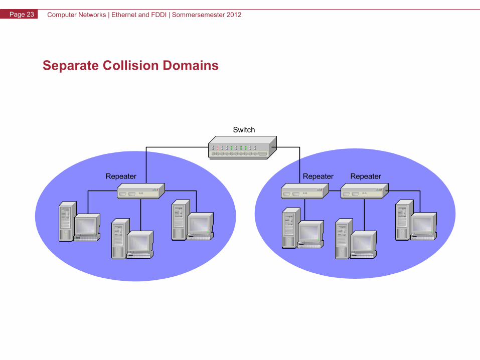
Separate Collision Domains
Repeater
Switch
RepeaterRepeater
Computer Networks | Ethernet and FDDI | Sommersemester 2012Page 24
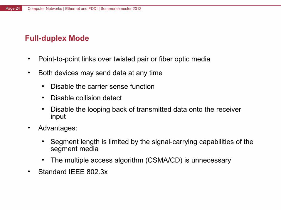
Full-duplex Mode
• Point-to-point links over twisted pair or fiber optic media
• Both devices may send data at any time
• Disable the carrier sense function
• Disable collision detect
• Disable the looping back of transmitted data onto the receiver input
• Advantages:
• Segment length is limited by the signal-carrying capabilities of the segment media
• The multiple access algorithm (CSMA/CD) is unnecessary
• Standard IEEE 802.3x
Computer Networks | Ethernet and FDDI | Sommersemester 2012Page 25
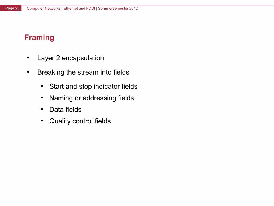
Framing
• Layer 2 encapsulation
• Breaking the stream into fields
• Start and stop indicator fields
• Naming or addressing fields
• Data fields
• Quality control fields
Computer Networks | Ethernet and FDDI | Sommersemester 2012Page 26
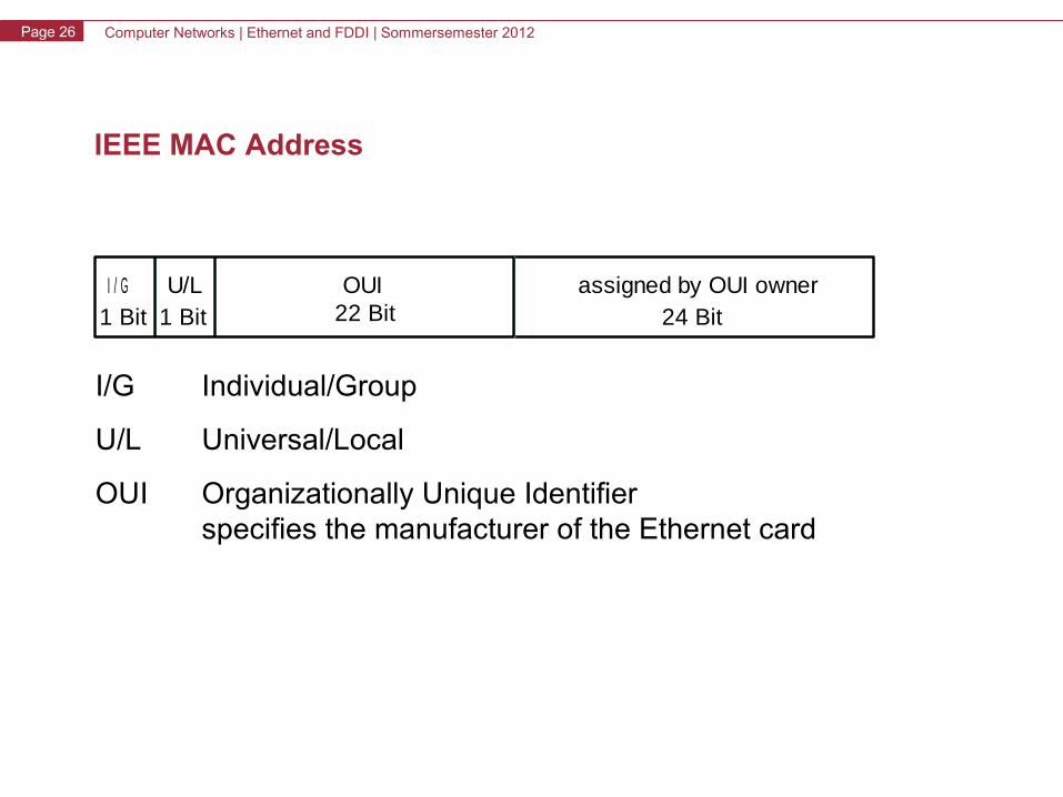
IEEE MAC Address
I/G Individual/Group
U/L Universal/Local
OUI Organizationally Unique Identifierspecifies the manufacturer of the Ethernet card
I / G U/L1 Bit1 Bit
OUI22 Bit
assigned by OUI owner24 Bit
Computer Networks | Ethernet and FDDI | Sommersemester 2012Page 27
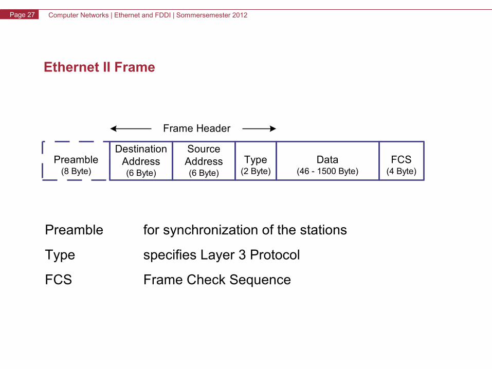
Ethernet II Frame
Preamble for synchronization of the stations
Type specifies Layer 3 Protocol
FCS Frame Check Sequence
Frame Header
FCS(4 Byte)
Data(46 - 1500 Byte)
DestinationAddress(6 Byte)
Preamble(8 Byte)
SourceAddress(6 Byte)
Type(2 Byte)
Computer Networks | Ethernet and FDDI | Sommersemester 2012Page 28
Ethernet and FDDI
• Ethernet– History, Evolution, Overview– OSI-Model
• Physical Layer: Coding Schemes• MAC-Layer: CSMA/CD
– Ethernet Principles• Versions and Parameters• Topologies• Communication Modes• Collision Domain• Framing
– Standards up to Gigabit Ethernet– Gigabit Ethernet– VLAN
• FDDI
Computer Networks | Ethernet and FDDI | Sommersemester 2012Page 29
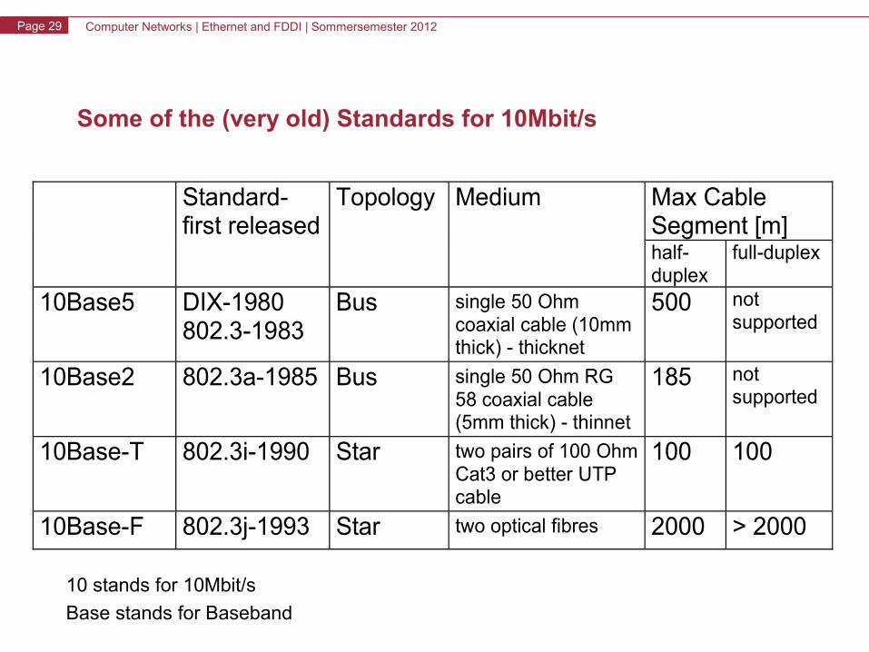
Some of the (very old) Standards for 10Mbit/s
Standard-first released
Topology Medium Max Cable Segment [m] half-duplex
full-duplex
10Base5 DIX-1980 802.3-1983
Bus single 50 Ohm coaxial cable (10mm thick) - thicknet
500 not supported
10Base2 802.3a-1985 Bus single 50 Ohm RG 58 coaxial cable (5mm thick) - thinnet
185 not supported
10Base-T 802.3i-1990 Star two pairs of 100 Ohm Cat3 or better UTP cable
100 100
10Base-F 802.3j-1993 Star two optical fibres 2000 > 2000
10 stands for 10Mbit/s
Base stands for Baseband
Computer Networks | Ethernet and FDDI | Sommersemester 2012Page 30
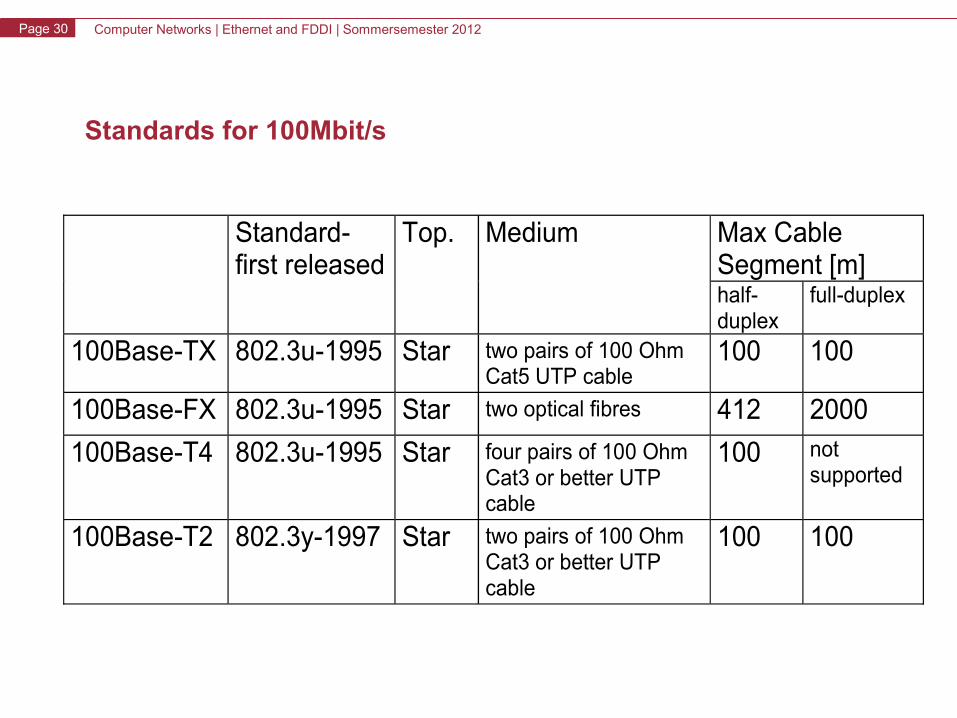
Standards for 100Mbit/s
Standard-first released
Top. Medium Max Cable Segment [m] half-duplex
full-duplex
100Base-TX 802.3u-1995 Star two pairs of 100 Ohm Cat5 UTP cable
100 100
100Base-FX 802.3u-1995 Star two optical fibres 412 2000
100Base-T4 802.3u-1995 Star four pairs of 100 Ohm Cat3 or better UTP cable
100 not supported
100Base-T2 802.3y-1997 Star two pairs of 100 Ohm Cat3 or better UTP cable
100 100
Computer Networks | Ethernet and FDDI | Sommersemester 2012Page 31
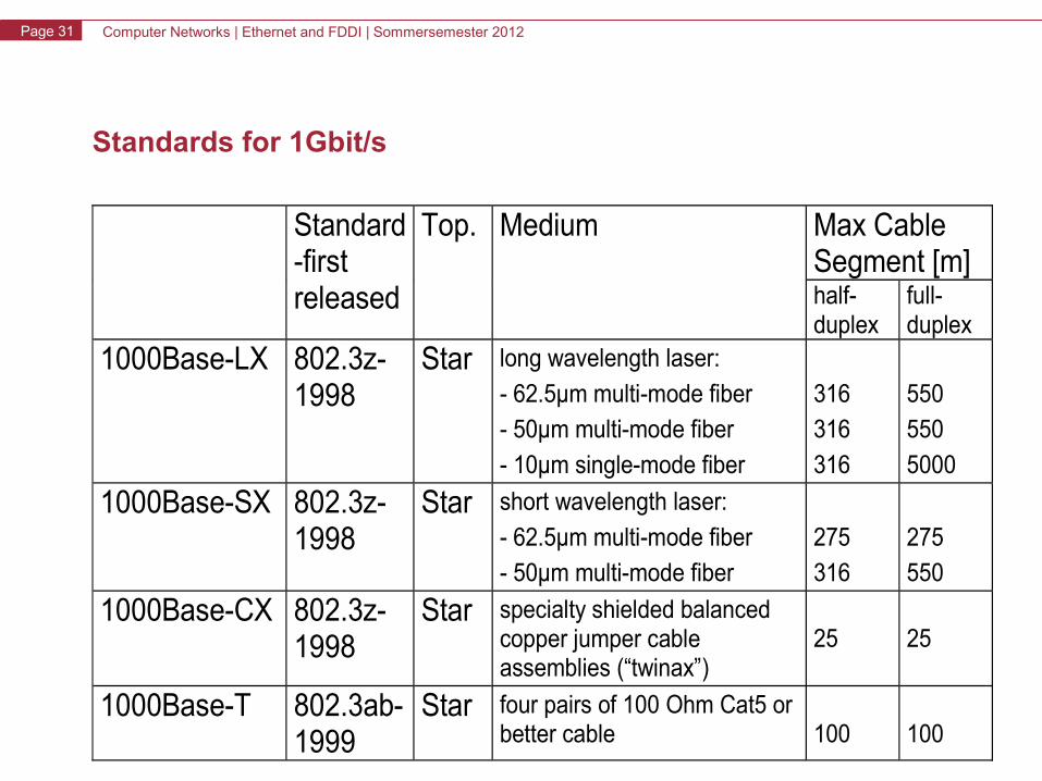
Standards for 1Gbit/s
Standard-first released
Top. Medium Max Cable Segment [m] half-duplex
full-duplex
1000Base-LX 802.3z-1998
Star long wavelength laser:
- 62.5μm multi-mode fiber
- 50μm multi-mode fiber
- 10μm single-mode fiber
316
316
316
550
550
5000
1000Base-SX 802.3z-1998
Star short wavelength laser:
- 62.5μm multi-mode fiber
- 50μm multi-mode fiber
275
316
275
550
1000Base-CX 802.3z-1998
Star specialty shielded balanced copper jumper cable assemblies (“twinax”)
25
25
1000Base-T 802.3ab-1999
Star four pairs of 100 Ohm Cat5 or better cable
100
100
Computer Networks | Ethernet and FDDI | Sommersemester 2012Page 32
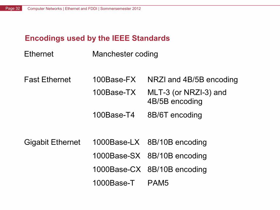
Encodings used by the IEEE Standards
Ethernet Manchester coding
Fast Ethernet 100Base-FX NRZI and 4B/5B encoding
100Base-TX MLT-3 (or NRZI-3) and4B/5B encoding
100Base-T4 8B/6T encoding
Gigabit Ethernet 1000Base-LX 8B/10B encoding
1000Base-SX 8B/10B encoding
1000Base-CX 8B/10B encoding
1000Base-T PAM5
Computer Networks | Ethernet and FDDI | Sommersemester 2012Page 33
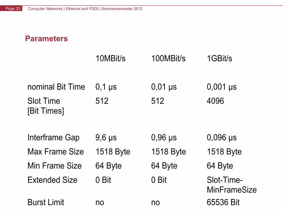
Parameters
10MBit/s 100MBit/s 1GBit/s
nominal Bit Time 0,1 μs 0,01 μs 0,001 μs
Slot Time [Bit Times]
512 512 4096
Interframe Gap 9,6 μs 0,96 μs 0,096 μs
Max Frame Size 1518 Byte 1518 Byte 1518 Byte
Min Frame Size 64 Byte 64 Byte 64 Byte
Extended Size 0 Bit 0 Bit Slot-Time-MinFrameSize
Burst Limit no no 65536 Bit
Computer Networks | Ethernet and FDDI | Sommersemester 2012Page 34
Ethernet and FDDI
• Ethernet– History, Evolution, Overview– OSI-Model
• Physical Layer: Coding Schemes• MAC-Layer: CSMA/CD
– Ethernet Principles• Versions and Parameters• Topologies• Communication Modes• Collision Domain• Framing
– Standards up to Gigabit Ethernet– Gigabit Ethernet– VLAN
• FDDI
Computer Networks | Ethernet and FDDI | Sommersemester 2012Page 35
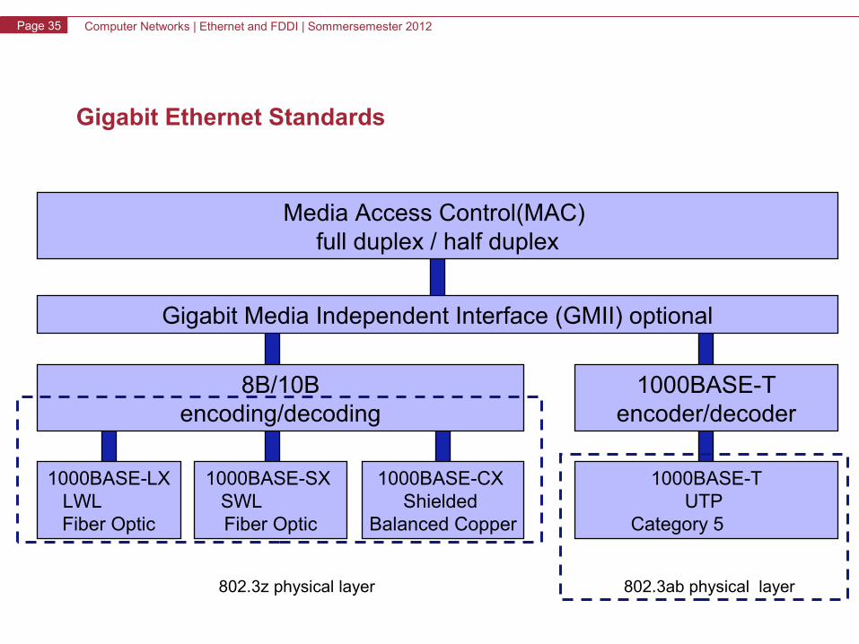
Gigabit Ethernet Standards
Media Access Control(MAC) full duplex / half duplex
Gigabit Media Independent Interface (GMII) optional
8B/10Bencoding/decoding
1000BASE-Tencoder/decoder
1000BASE-LX LWL Fiber Optic
1000BASE-SX SWL Fiber Optic
1000BASE-CX Shielded
Balanced Copper
1000BASE-TUTP
Category 5
802.3z physical layer 802.3ab physical layer
Computer Networks | Ethernet and FDDI | Sommersemester 2012Page 36
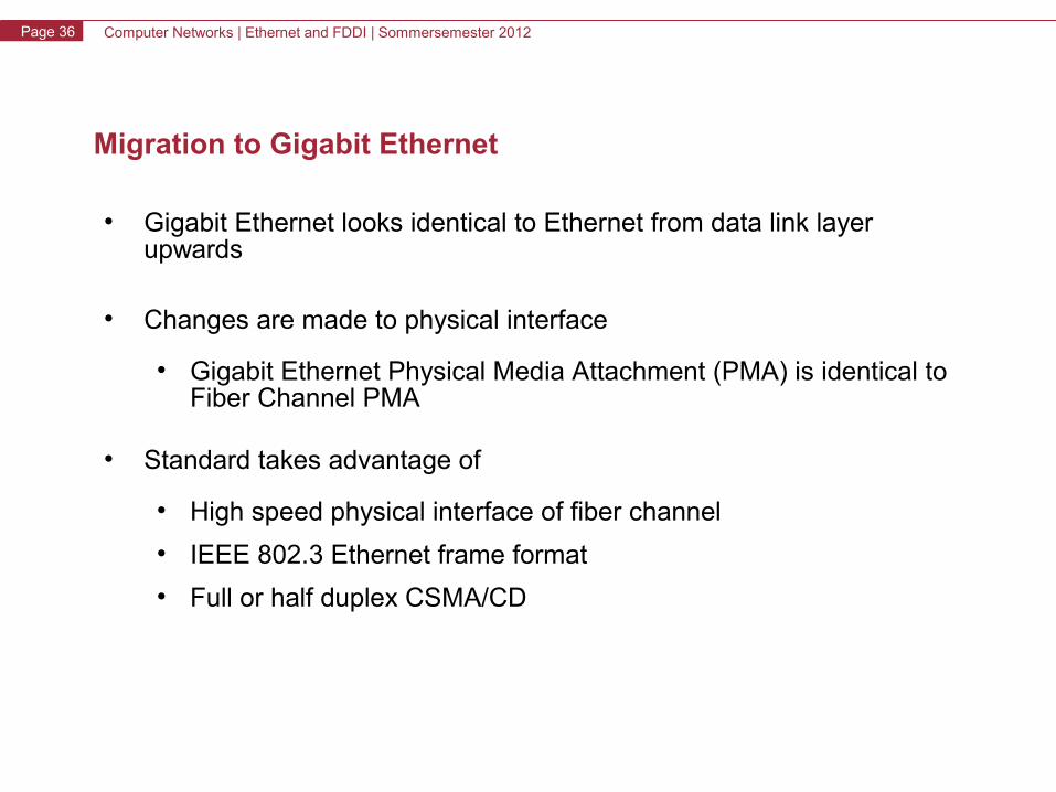
Migration to Gigabit Ethernet
• Gigabit Ethernet looks identical to Ethernet from data link layer upwards
• Changes are made to physical interface
• Gigabit Ethernet Physical Media Attachment (PMA) is identical to Fiber Channel PMA
• Standard takes advantage of
• High speed physical interface of fiber channel
• IEEE 802.3 Ethernet frame format
• Full or half duplex CSMA/CD
Computer Networks | Ethernet and FDDI | Sommersemester 2012Page 37
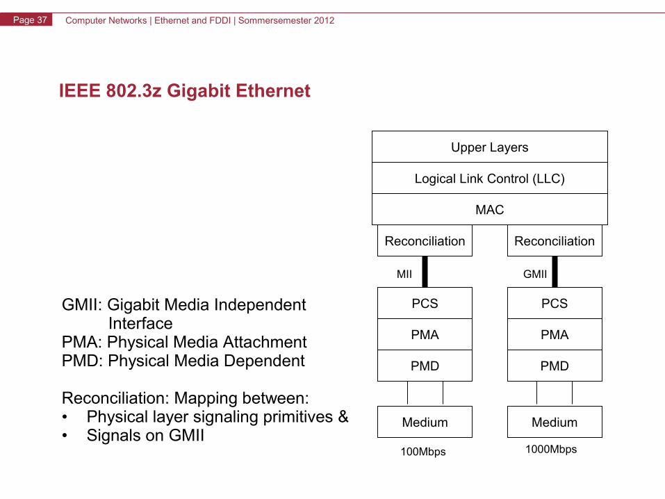
IEEE 802.3z Gigabit Ethernet
Upper Layers
Logical Link Control (LLC)
MAC
ReconciliationReconciliation
PCSPCS
PMA
PMD
PMA
PMD
Medium Medium
100Mbps 1000Mbps
MII GMII
GMII: Gigabit Media Independent InterfacePMA: Physical Media AttachmentPMD: Physical Media Dependent
Reconciliation: Mapping between:• Physical layer signaling primitives &• Signals on GMII
Computer Networks | Ethernet and FDDI | Sommersemester 2012Page 38
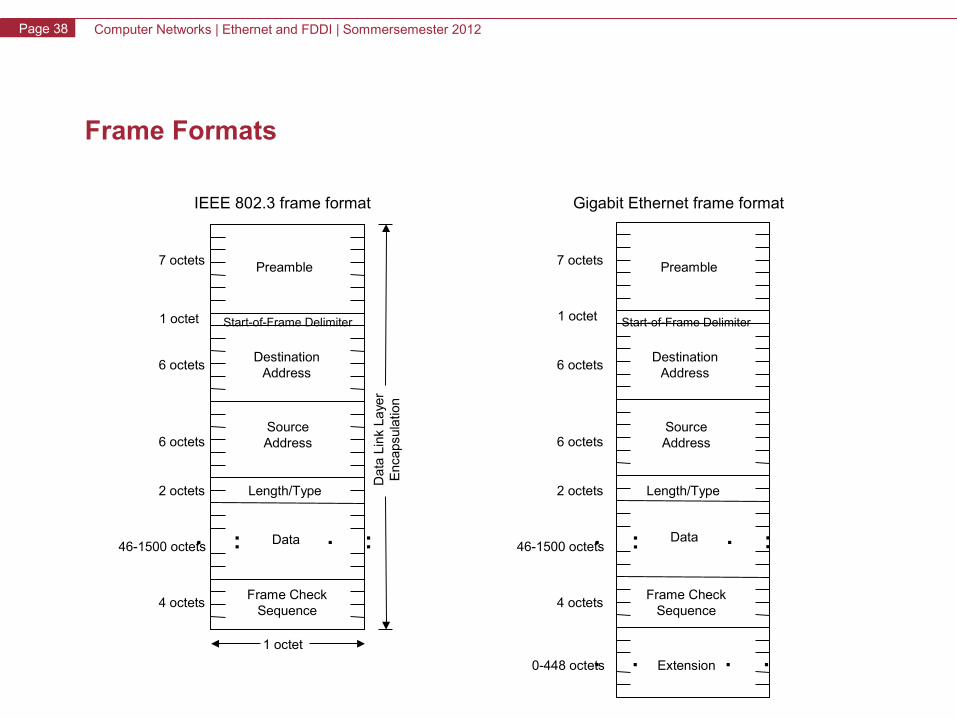
Frame Formats
... ...
.. ..
... ...
Preamble
Da
ta L
ink
Laye
rE
ncap
sula
tion
Start-of-Frame Delimiter
DestinationAddress
SourceAddress
Length/Type
Data
Frame CheckSequence
7 octets
1 octet
6 octets
6 octets
2 octets
46-1500 octets
4 octets
Preamble
Start-of-Frame Delimiter
DestinationAddress
SourceAddress
Length/Type
Data
Frame CheckSequence
7 octets
1 octet
6 octets
6 octets
2 octets
46-1500 octets
4 octets
1 octet
IEEE 802.3 frame format Gigabit Ethernet frame format
0-448 octets Extension
Computer Networks | Ethernet and FDDI | Sommersemester 2012Page 39
Problems with Gigabit Ethernet
In half-duplex mode, the physical extension would - without further
measures - be less than 20 meters
Reason: dependence between minimum sized frames, speed and physical extension
The minimum CSMA/CD carrier time and the Ethernet slot time have been extended to 512 bytes.
Packets 512 bytes are not modified
Packets < 512 bytes have a carrier extension field following the CRC field
Computer Networks | Ethernet and FDDI | Sommersemester 2012Page 40
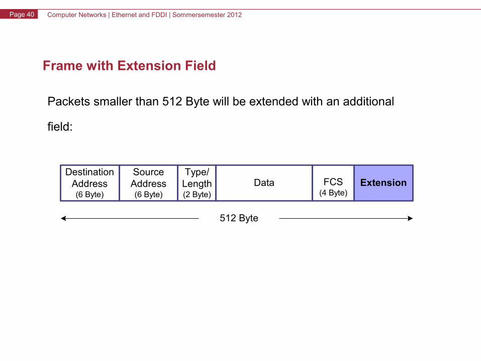
Frame with Extension Field
Packets smaller than 512 Byte will be extended with an additional
field:
FCS(4 Byte)
DataDestination
Address(6 Byte)
SourceAddress(6 Byte)
Type/Length(2 Byte)
Extension
512 Byte
Computer Networks | Ethernet and FDDI | Sommersemester 2012Page 41
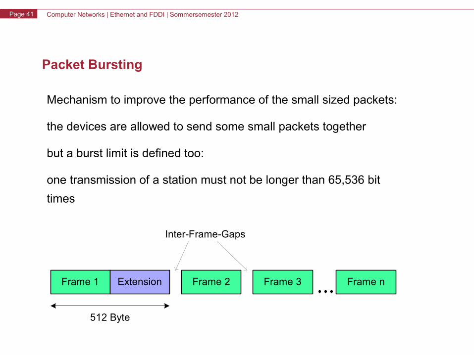
Packet Bursting
Mechanism to improve the performance of the small sized packets:
the devices are allowed to send some small packets together
but a burst limit is defined too:
one transmission of a station must not be longer than 65,536 bit
times
512 Byte
Frame 1 Extension Frame 2 Frame 3 Frame n
Inter-Frame-Gaps
Computer Networks | Ethernet and FDDI | Sommersemester 2012Page 42
Ethernet and FDDI
• Ethernet– History, Evolution, Overview– OSI-Model
• Physical Layer: Coding Schemes• MAC-Layer: CSMA/CD
– Ethernet Principles• Versions and Parameters• Topologies• Communication Modes• Collision Domain• Framing
– Standards up to Gigabit Ethernet– Gigabit Ethernet– VLAN
• FDDI
Computer Networks | Ethernet and FDDI | Sommersemester 2012Page 43
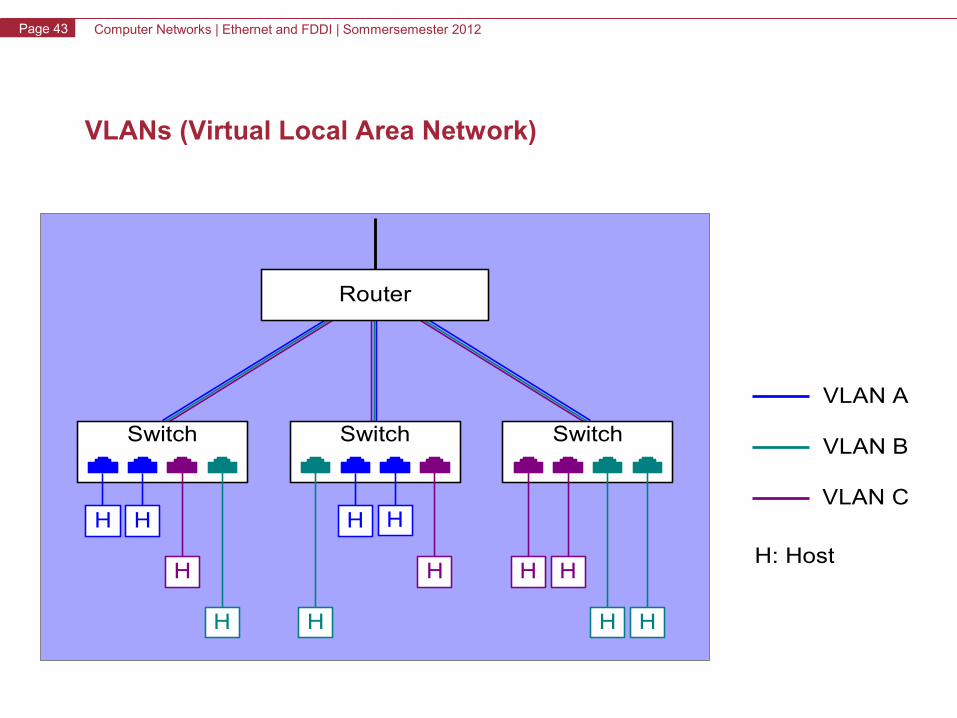
VLANs (Virtual Local Area Network)
Router
VLAN A
VLAN B
VLAN C
SwitchSwitchSwitch
H H
HH
HHH
HH
H
HH
H: Host
Computer Networks | Ethernet and FDDI | Sommersemester 2012Page 44
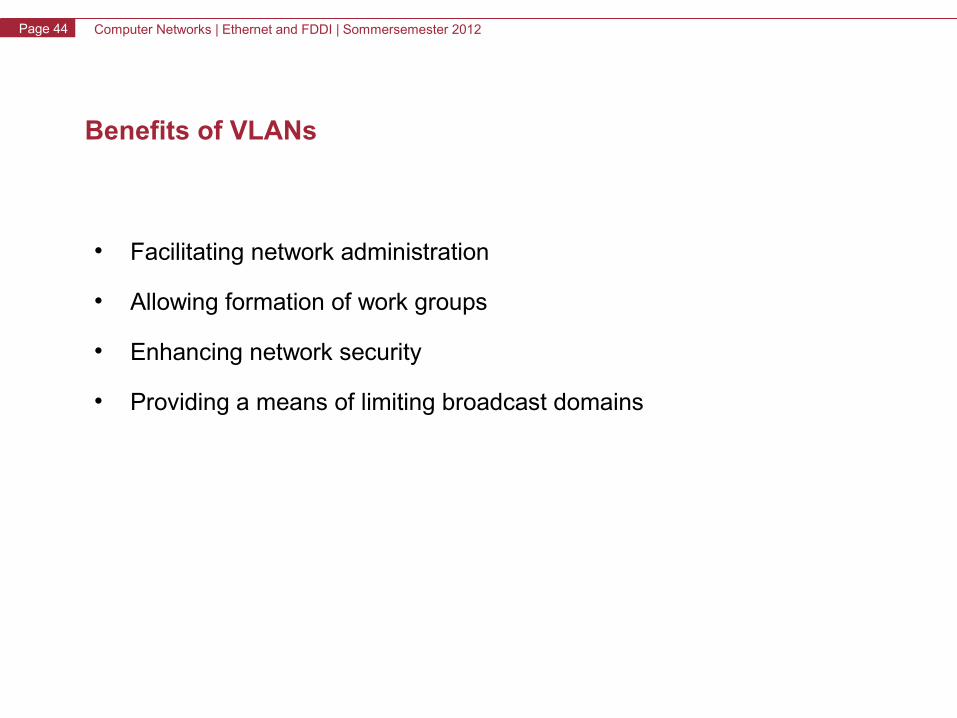
Benefits of VLANs
• Facilitating network administration
• Allowing formation of work groups
• Enhancing network security
• Providing a means of limiting broadcast domains
Computer Networks | Ethernet and FDDI | Sommersemester 2012Page 45
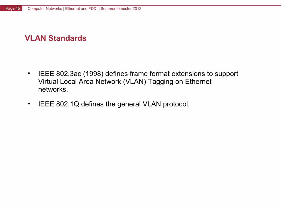
VLAN Standards
• IEEE 802.3ac (1998) defines frame format extensions to support Virtual Local Area Network (VLAN) Tagging on Ethernetnetworks.
• IEEE 802.1Q defines the general VLAN protocol.
Computer Networks | Ethernet and FDDI | Sommersemester 2012Page 46
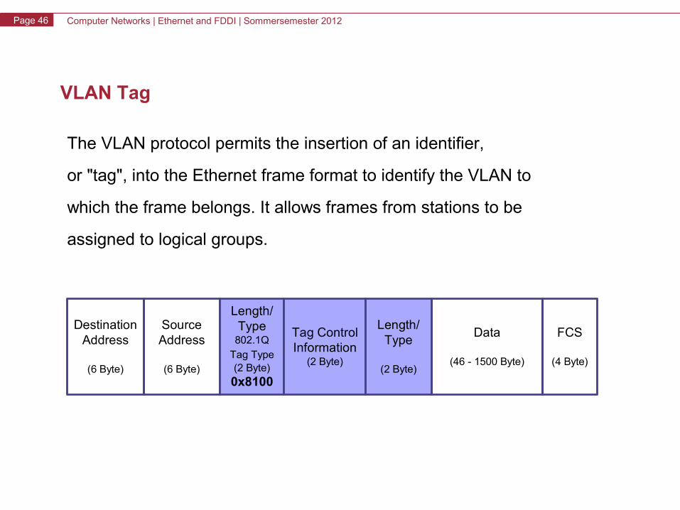
VLAN Tag
The VLAN protocol permits the insertion of an identifier,
or "tag", into the Ethernet frame format to identify the VLAN to
which the frame belongs. It allows frames from stations to be
assigned to logical groups.
FCS
(4 Byte)
Data
(46 - 1500 Byte)
DestinationAddress
(6 Byte)
SourceAddress
(6 Byte)
Length/Type
802.1QTag Type(2 Byte)0x8100
Tag ControlInformation
(2 Byte)
Length/Type
(2 Byte)
Computer Networks | Ethernet and FDDI | Sommersemester 2012Page 47
Ethernet and FDDI
• Ethernet– History, Evolution, Overview– OSI-Model
• Physical Layer: Coding Schemes• MAC-Layer: CSMA/CD
– Ethernet Principles• Versions and Parameters• Topologies• Communication Modes• Collision Domain• Framing
– Standards up to Gigabit Ethernet– Gigabit Ethernet– VLAN
• FDDI
Computer Networks | Ethernet and FDDI | Sommersemester 2012Page 48
FDDI (Fiber Distributed Data Interface)
• 100Mbps bandwidth
• Up to 500 stations in one network
• Up to 60km between two stations
• Total length 200km
• Guaranteed waiting time
• Redundancy in topology
Computer Networks | Ethernet and FDDI | Sommersemester 2012Page 49
FDDI Summary
• Fixed 125Mbps 4b/5b coded signals
• Timed token rotation used for bandwidth sharing
• Frame size 3...4500 bytes
• Topology: dual ring of trees
• Big-endian bit order
• Offers synchronous and asynchronous transmissions
• Stations have station-management duties
Computer Networks | Ethernet and FDDI | Sommersemester 2012Page 50
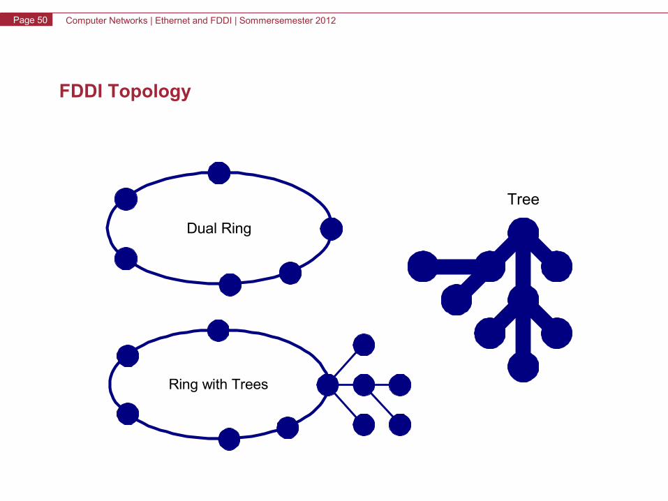
FDDI Topology
Dual Ring
Ring with Trees
Tree
Computer Networks | Ethernet and FDDI | Sommersemester 2012Page 51
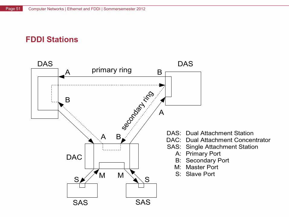
FDDI Stations
primary ringDASDAS
DAC
SAS SAS
B
B
BA
A
A
MMSS
DAS: Dual Attachment StationDAC: Dual Attachment ConcentratorSAS: Single Attachment Station
A: Primary PortB: Secondary PortM: Master PortS: Slave Port
Computer Networks | Ethernet and FDDI | Sommersemester 2012Page 52
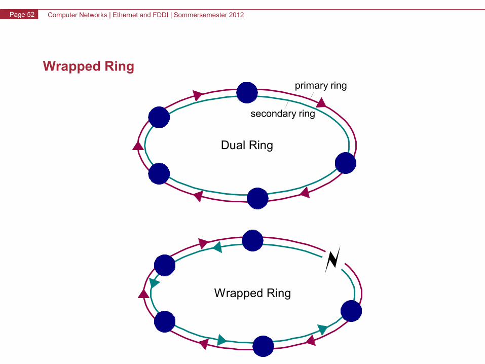
Wrapped Ring
Dual Ring
primary ring
secondary ring
Wrapped Ring
Computer Networks | Ethernet and FDDI | Sommersemester 2012Page 53
FDDI Frame
StartingDelimiter(2 symbols)
Information
(<= 8956)
DestinationAddress
(12 symbols)
FrameControl
(2 symbols)
SourceAddress
(12 symbols)
EndingDelimiter(1 symbol)
FrameStatus
(3 symbols)
ErrorDetected(1 symbol)
FrameCopied
(1 symbol)
AddressRecognized
(1 symbol)
C L F F Z Z Z Z
Type of Frame
Length of Address0=16bits, 1=48bits
Class of Service0=asynchronous, 1=synchronous
Computer Networks | Ethernet and FDDI | Sommersemester 2012Page 54
Access Method
Computer Networks | Ethernet and FDDI | Sommersemester 2012Page 55
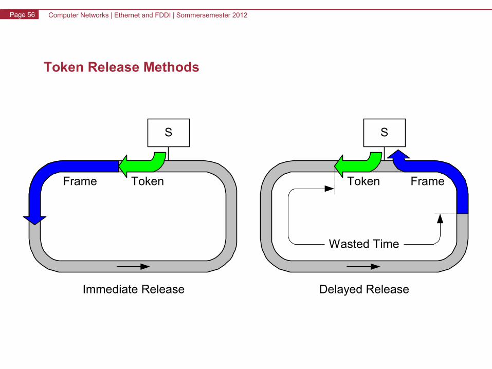
FDDI Access Method
• There are 2 types of transfers: synchronous and asynchronous
• Synchronous transfers can be done whenever the station gets the
token; was never really used
• Asynchronous traffic can be started whenever the station gets a
token that is not late
• The last frame is always allowed to complete
• The token is immediately released after transmission
• The transmitting station removes its own data
Computer Networks | Ethernet and FDDI | Sommersemester 2012Page 56
Token Release Methods
S
TokenFrame
Immediate Release
S
Token Frame
Delayed Release
Wasted Time
Computer Networks | Ethernet and FDDI | Sommersemester 2012Page 57
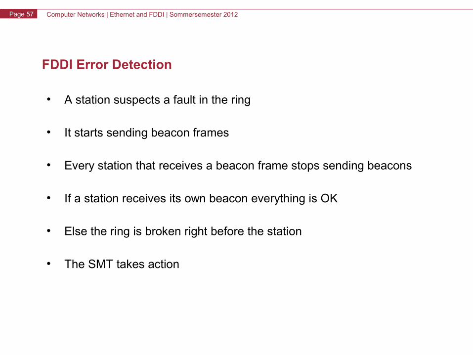
FDDI Error Detection
• A station suspects a fault in the ring
• It starts sending beacon frames
• Every station that receives a beacon frame stops sending beacons
• If a station receives its own beacon everything is OK
• Else the ring is broken right before the station
• The SMT takes action
Computer Networks | Ethernet and FDDI | Sommersemester 2012Page 58
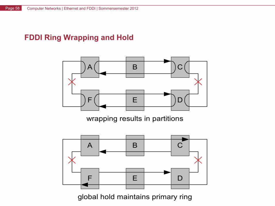
FDDI Ring Wrapping and Hold
F E D
A CB
wrapping results in partitions
F E D
A CB
global hold maintains primary ring