Embed Size (px)
Citation preview

Release 2015.0 May 6, 2015 1 © 2015 ANSYS, Inc.
2015.0 Release
Lecture 9: Unit Cell Analysis (Infinite Array)
ANSYS HFSS for Antenna Design

Release 2015.0 May 6, 2015 2 © 2015 ANSYS, Inc.
Array Overview
• Phased Array • A group of antenna elements in which the relative amplitudes and phases are varied to construct an effective radiation pattern by
constructive and destructive interference
• Beam shape can be controlled by adjusting the amplitude of each element
• Beam can be steered by applying a progressing phase shift across the array.
• Mutual coupling plays a key role in an element’s pattern and input impedance.
• It is necessary to analyze the arrays performance over frequency and scan volume.
Amplitude
Phase
n
n
n
rjkj
oonooarray Er
eeAE
no
oon ),(),(),,,(),(
n
nmj
oom
j
oonoom S
eA
eAS
oom
oon
,),(
),(
),(
),(),(

Release 2015.0 May 6, 2015 3 © 2015 ANSYS, Inc.
Analysis Approaches
Unit Cell
• Uses Master/Slave boundaries • models a single element as if it were
in an infinite array environment
• Infinite array environment accounted
for by enforcing field periodicity
through master/slave boundary pairs.
• Reduces RAM
• Reduces solve time
• Infinite Array Approx. • Edge affects ignored
• Uniform magnitude excitation
• Single scan angle solved at a time
(Distributed Solve Option Parallelizes)
Finite Array
Explicit • Entire array analyzed
• Accounts for edge affects and
edge treatments
• Provides mutual coupling
terms
• Allows magnitude taper
• Most flexible • Fewest assumptions
• Adaptive meshing performed
on entire model
• Complex Geometry • Every element needs to be
drawn
• Large number of excitations
• Complicated meshing process
Finite Array DDM • Entire array analyzed
• Accounts for edge affects
• Provides mutual coupling
terms
• Allows magnitude taper
• Adaptive meshing performed
on single unit cell
• Uses Domain Decomposition
to minimize and distribute
compute resources
• Distributes RAM
• Reduces solve time
• Periodic assumption • Geometry must be purely
periodic in the XY plane

Release 2015.0 May 6, 2015 4 © 2015 ANSYS, Inc.
Unit Cell Analysis with Master / Slave Boundaries
Release 2015.0 May 6, 2015 5 © 2015 ANSYS, Inc.
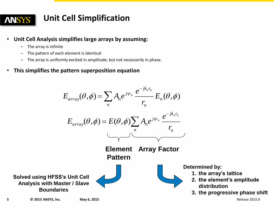
Unit Cell Simplification
• Unit Cell Analysis simplifies large arrays by assuming: – The array is infinite
– The pattern of each element is identical
– The array is uniformly excited in amplitude, but not necessarily in phase.
• This simplifies the pattern superposition equation
n
n
n
rjkj
narray Er
eeAE
no
n ),(),(
n n
rjkj
narrayr
eeAEE
no
n ),(),(
Element
Pattern
Array Factor
Determined by:
1. the array’s lattice
2. the element’s amplitude
distribution
3. the progressive phase shift
Solved using HFSS’s Unit Cell
Analysis with Master / Slave
Boundaries

Release 2015.0 May 6, 2015 6 © 2015 ANSYS, Inc.
Master/Slave Boundaries
• Used to model unit cell of periodic structures
• Master and slave boundaries are always paired • Fields on master surface are mapped to slave surface with a phase shift enforcing a periodicity in the fields.
• Constraints • Master and slave surfaces must be identical in shape and size
• Coordinate systems must be created to identify point-to-point correspondence
Unit Cell Model
of Waveguide Array
WG Port
(bottom)
Master
Boundary
Slave
Boundary
V-axis
U-axis

Release 2015.0 May 6, 2015 7 © 2015 ANSYS, Inc.
Unit Cell Creation
• Unit Cell shape describes the array’s lattice • The shape should recreate the array’s periodicity
Rectangular Lattice Triangular Lattice
Rectangle Hexagon Rectangle Parallelogram

Release 2015.0 May 6, 2015 8 © 2015 ANSYS, Inc.
What if the Lattice is Triangular
• Triangular Lattice • A and B vectors should point from one element to the next adjacent element.
• Alternatively they should point from a master boundary to its corresponding slave boundary (or visa versa).

Release 2015.0 May 6, 2015 9 © 2015 ANSYS, Inc.
Verifying the Unit Cell Geometry
• When an element is duplicated along a periodicity the Master boundary should make contact with the adjacent cell’s slave boundary
M1 M2
M3
S1 S2
S3
M1 M2
M3
S1 S2
S3
M1 M2
M3
S1 S2
S3
M1 M2
M3
S1 S2
S3
M1 M2
M3
S1 S2
S3
M1
M2
M3
S1 S2
S3
M1
M2
M3
S1 S2
S3

Release 2015.0 May 6, 2015 10 © 2015 ANSYS, Inc.
Floquet Ports Overview
• Floquet Port • Excites and terminates waves propagating down the unit cell
• Always Linked to Master/Slave Boundaries
– Establishes field periodicity of the array
• Only for surfaces exposed to the background
• Replaces radiation boundary and PML for free space field absorption
• How do Floquet Ports Excite and Terminate Power • Decomposes the fields on the Floquet Port into
Floquet Modes
– Set of TE and TM modes in which the power travels
– Similar concept to Waveguide Modes
• Floquet Ports only absorb the modes that are defined on the port
– All other modes are short circuited back into the model
• Post-Processing Floquet Ports • Supports multiple modes and de-embedding
• Computes Generalized S-Parameters
– Frequency dependent characteristic impedance (Zo)
– Frequency dependent propagation constant
– Perfectly matched at every frequency and every scan angle
All significant mode need to be defined in the Floquet Port Setup to obtain accurate solutions.

Release 2015.0 May 6, 2015 11 © 2015 ANSYS, Inc.
Floquet Mode Visualization
• Each floquet mode: 1. is a plane wave propagating in a given direction
2. represents a main beam or grating lobe of the array
Dominant Mode
(Main Beam)
Scanned to (,) = (45o,0o)
Higher Order Mode
(Grating Lobe)
Scanned to (,) = (-45o,0o)
Power Flow
Unit Cell
Transmission Line
Axis

Release 2015.0 May 6, 2015 12 © 2015 ANSYS, Inc.
Floquet Port Setup
• Affects 3D Refinement • Determines which modes are excited during 3D Refinement
– Modes excluded have NO impact on the mesh density
• Eliminating an excitation from the 3D Refinement Process
– Simplifies the analysis
– Can overcome convergence issues
• For phased array element analysis uncheck all the modes.
– The primary purpose of the Floquet Port is to terminate the array’s radiated power and determine how the element transmits power to different Floquet Modes.
– The transmission terms from the antenna to the Floquet Modes will be accurate because the antenna’s ports are always included in the 3D Refinement process.
– The only questionable results will be the transmission and reflection terms where the power emanates from the Floquet Port itself.
Port 1
Po
rt 2
Port 3
Po
rt 4
Mesh for Random
Multiport Device
Port 1
Po
rt 2
Port 3
Po
rt 4
Regions Requiring
Mesh Refinement
Port 1
Po
rt 2
Port 3
Po
rt 4
Regions Requiring Mesh
Refinement with Port 3 Excluded


![[Array, Array, Array, Array, Array, Array, Array, Array, Array, Array, Array, Array]](https://img.pdfslide.us/doc/110x75/56816460550346895dd63b8b/array-array-array-array-array-array-array-array-array-array-array.jpg)