Embed Size (px)
Citation preview
520/530/580.495 Microfabrication Laboratory
and520.773
Advanced Topics inFabrication and Microengineering
Lecture 9
Dry Etching
Reading for this lecture:(1) May, Chapter 5.2(2) Williams paper
HW #6: Due Nov. 6
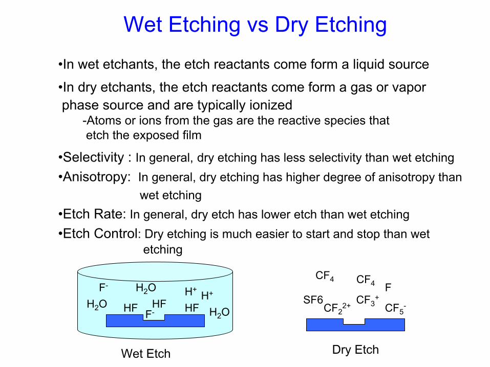
HFH+F-
H2OF-
H+H2O
H2OHFHF
Wet Etch
CF4
CF5-CF2
2+
CF4
SF6F
CF3+
Dry Etch
Wet Etching vs Dry Etching
•In wet etchants, the etch reactants come form a liquid source
•In dry etchants, the etch reactants come form a gas or vapor phase source and are typically ionized
-Atoms or ions from the gas are the reactive species that etch the exposed film
•Selectivity : In general, dry etching has less selectivity than wet etching•Anisotropy: In general, dry etching has higher degree of anisotropy than
wet etching•Etch Rate: In general, dry etch has lower etch than wet etching•Etch Control: Dry etching is much easier to start and stop than wet
etching
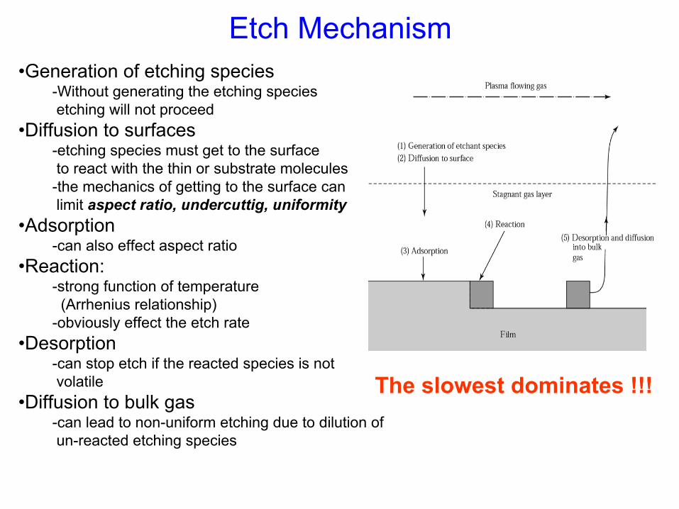
Etch Mechanism
The slowest dominates !!!
•Generation of etching species-Without generating the etching speciesetching will not proceed
•Diffusion to surfaces-etching species must get to the surfaceto react with the thin or substrate molecules
-the mechanics of getting to the surface can limit aspect ratio, undercuttig, uniformity
•Adsorption -can also effect aspect ratio
•Reaction:-strong function of temperature
(Arrhenius relationship)-obviously effect the etch rate
•Desorption-can stop etch if the reacted species is not volatile
•Diffusion to bulk gas-can lead to non-uniform etching due to dilution ofun-reacted etching species
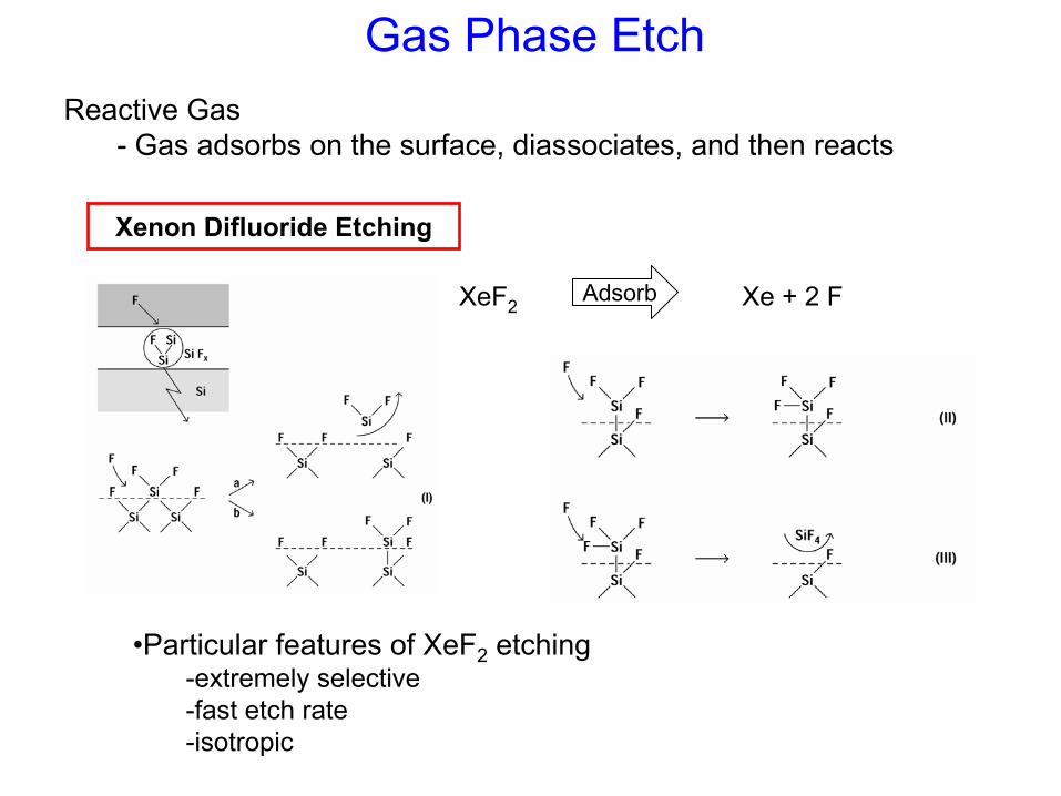
Gas Phase EtchReactive Gas
- Gas adsorbs on the surface, diassociates, and then reacts
Xenon Difluoride Etching
XeF2Adsorb Xe + 2 F
•Particular features of XeF2 etching-extremely selective-fast etch rate-isotropic
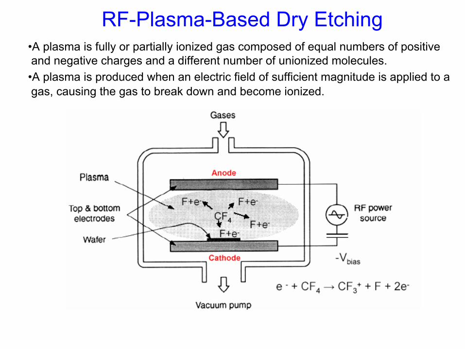
RF-Plasma-Based Dry Etching•A plasma is fully or partially ionized gas composed of equal numbers of positive and negative charges and a different number of unionized molecules.•A plasma is produced when an electric field of sufficient magnitude is applied to a gas, causing the gas to break down and become ionized.
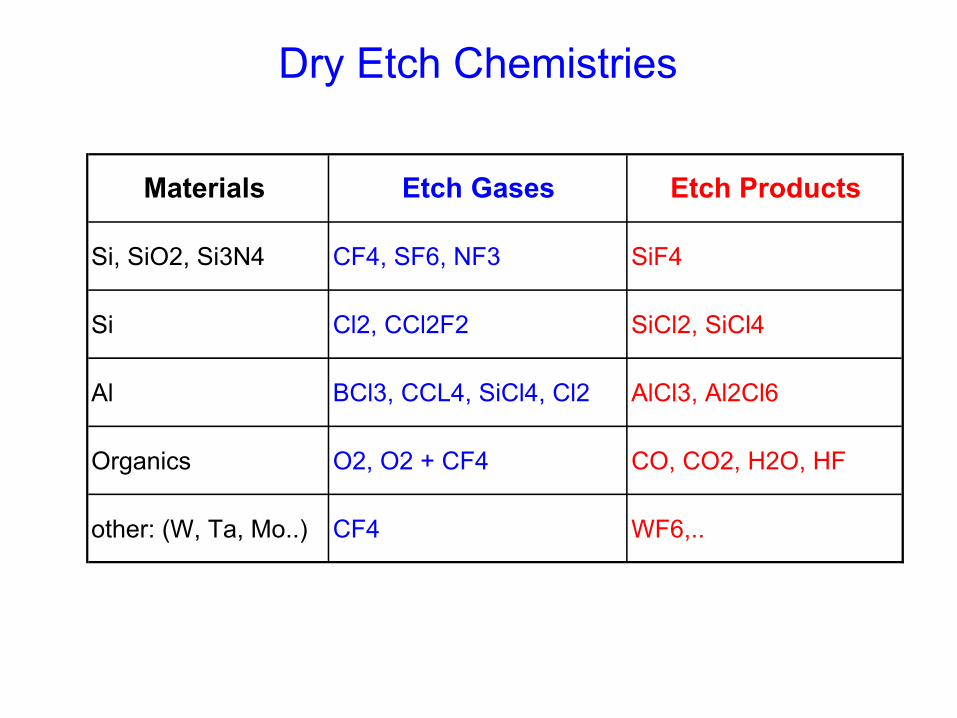
Materials Etch Gases Etch Products
Si, SiO2, Si3N4 CF4, SF6, NF3 SiF4
Si Cl2, CCl2F2 SiCl2, SiCl4
Al BCl3, CCL4, SiCl4, Cl2 AlCl3, Al2Cl6
Organics O2, O2 + CF4 CO, CO2, H2O, HF
other: (W, Ta, Mo..) CF4 WF6,..
Dry Etch Chemistries
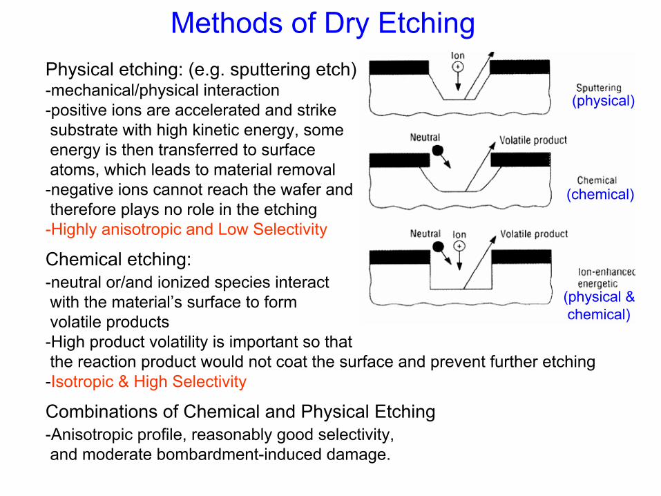
Methods of Dry Etching
(physical)
(physical &chemical)
(chemical)
Physical etching: (e.g. sputtering etch)-mechanical/physical interaction-positive ions are accelerated and strike substrate with high kinetic energy, some energy is then transferred to surfaceatoms, which leads to material removal-negative ions cannot reach the wafer and therefore plays no role in the etching -Highly anisotropic and Low Selectivity
Chemical etching: -neutral or/and ionized species interactwith the material’s surface to form volatile products-High product volatility is important so thatthe reaction product would not coat the surface and prevent further etching-Isotropic & High Selectivity
Combinations of Chemical and Physical Etching-Anisotropic profile, reasonably good selectivity, and moderate bombardment-induced damage.
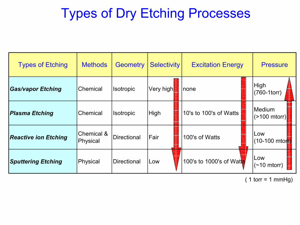
Types of Dry Etching Processes
( 1 torr = 1 mmHg)
Types of Etching Methods Geometry Selectivity Excitation Energy Pressure
Gas/vapor Etching Chemical Isotropic Very high none High (760-1torr)
Plasma Etching Chemical Isotropic High 10's to 100's of Watts Medium (>100 mtorr)
Reactive ion Etching Chemical & Physical Directional Fair 100's of Watts Low
(10-100 mtorr)
Sputtering Etching Physical Directional Low 100's to 1000's of Watts Low (~10 mtorr)
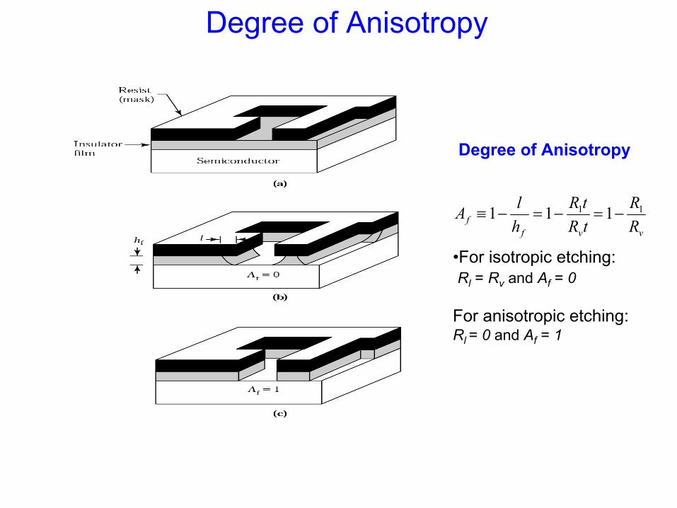
Degree of Anisotropy
Degree of Anisotropy
vvff R
RtRtR
hlA 11 111 −=−=−≡
•For isotropic etching:Rl = Rv and Af = 0
For anisotropic etching:Rl = 0 and Af = 1
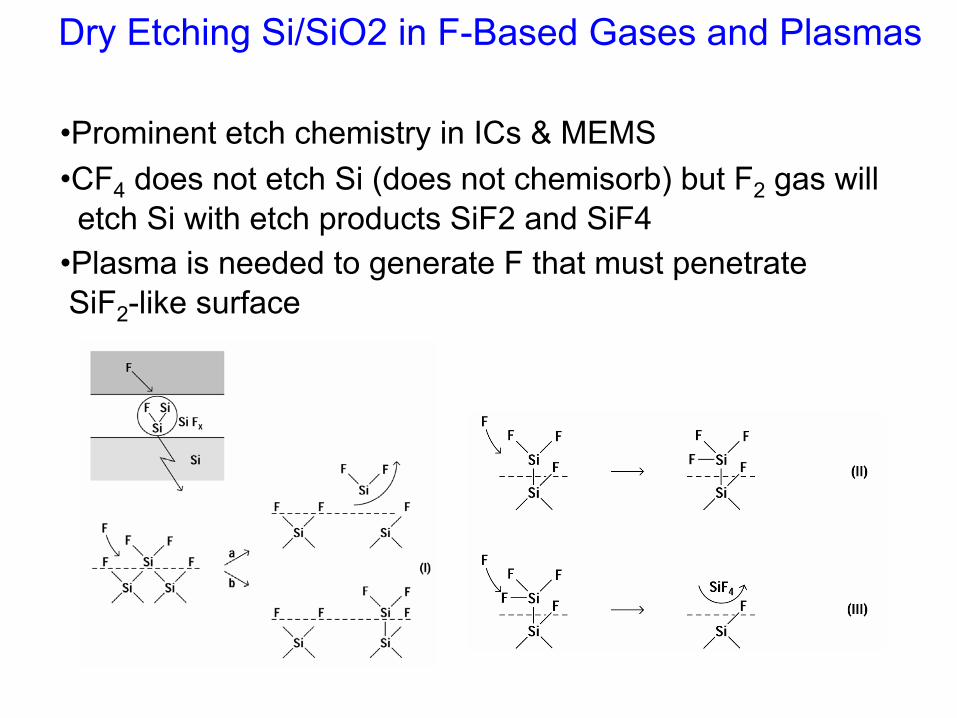
Dry Etching Si/SiO2 in F-Based Gases and Plasmas
•Prominent etch chemistry in ICs & MEMS•CF4 does not etch Si (does not chemisorb) but F2 gas will etch Si with etch products SiF2 and SiF4
•Plasma is needed to generate F that must penetrate SiF2-like surface
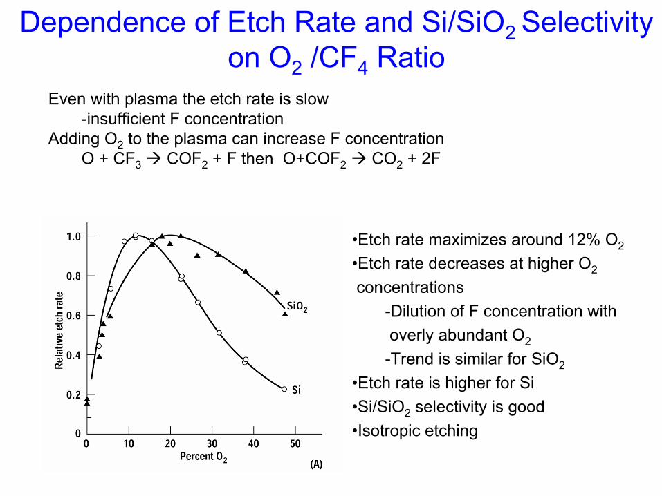
Dependence of Etch Rate and Si/SiO2 Selectivityon O2 /CF4 Ratio
Even with plasma the etch rate is slow-insufficient F concentration
Adding O2 to the plasma can increase F concentrationO + CF3 COF2 + F then O+COF2 CO2 + 2F
•Etch rate maximizes around 12% O2
•Etch rate decreases at higher O2
concentrations-Dilution of F concentration with overly abundant O2
-Trend is similar for SiO2
•Etch rate is higher for Si•Si/SiO2 selectivity is good•Isotropic etching
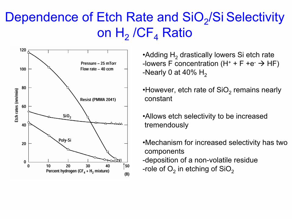
•Adding H2 drastically lowers Si etch rate-lowers F concentration (H+ + F +e- HF)-Nearly 0 at 40% H2
•However, etch rate of SiO2 remains nearly constant
•Allows etch selectivity to be increased tremendously
•Mechanism for increased selectivity has twocomponents-deposition of a non-volatile residue-role of O2 in etching of SiO2
Dependence of Etch Rate and SiO2/Si Selectivityon H2 /CF4 Ratio
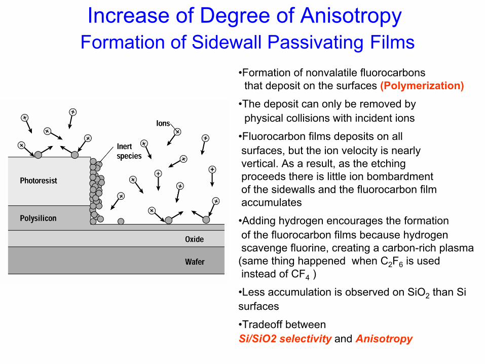
Increase of Degree of Anisotropy Formation of Sidewall Passivating Films
•Formation of nonvalatile fluorocarbons that deposit on the surfaces (Polymerization)
•The deposit can only be removed byphysical collisions with incident ions
•Fluorocarbon films deposits on all surfaces, but the ion velocity is nearlyvertical. As a result, as the etchingproceeds there is little ion bombardment of the sidewalls and the fluorocarbon film accumulates
•Adding hydrogen encourages the formationof the fluorocarbon films because hydrogenscavenge fluorine, creating a carbon-rich plasma(same thing happened when C2F6 is used instead of CF4 )
•Less accumulation is observed on SiO2 than Sisurfaces
•Tradeoff between Si/SiO2 selectivity and Anisotropy
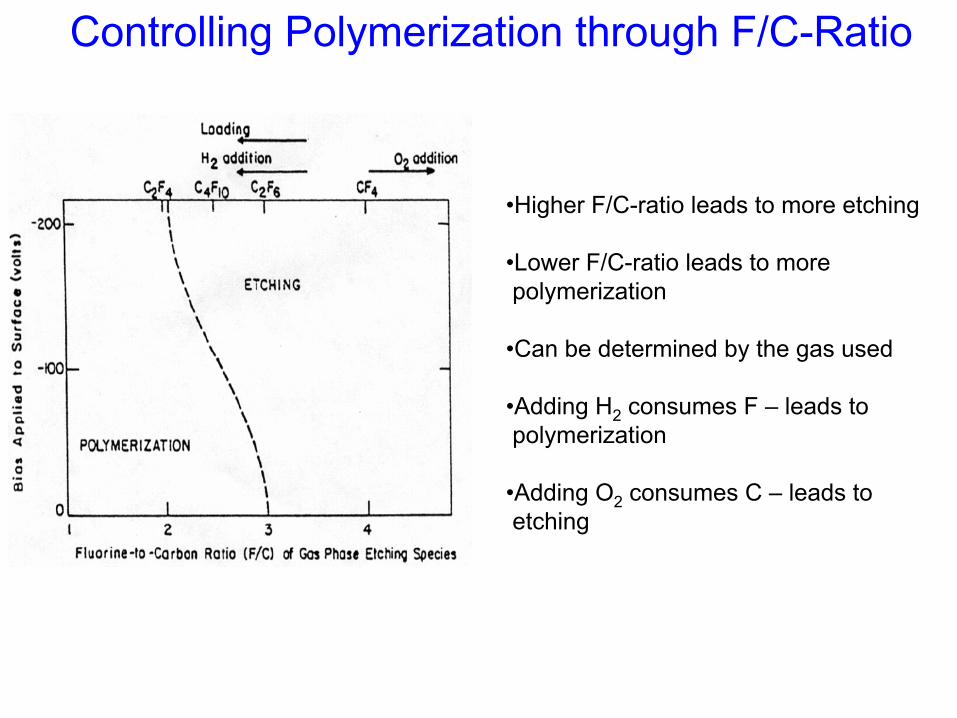
Controlling Polymerization through F/C-Ratio
•Higher F/C-ratio leads to more etching
•Lower F/C-ratio leads to more polymerization
•Can be determined by the gas used
•Adding H2 consumes F – leads to polymerization
•Adding O2 consumes C – leads to etching
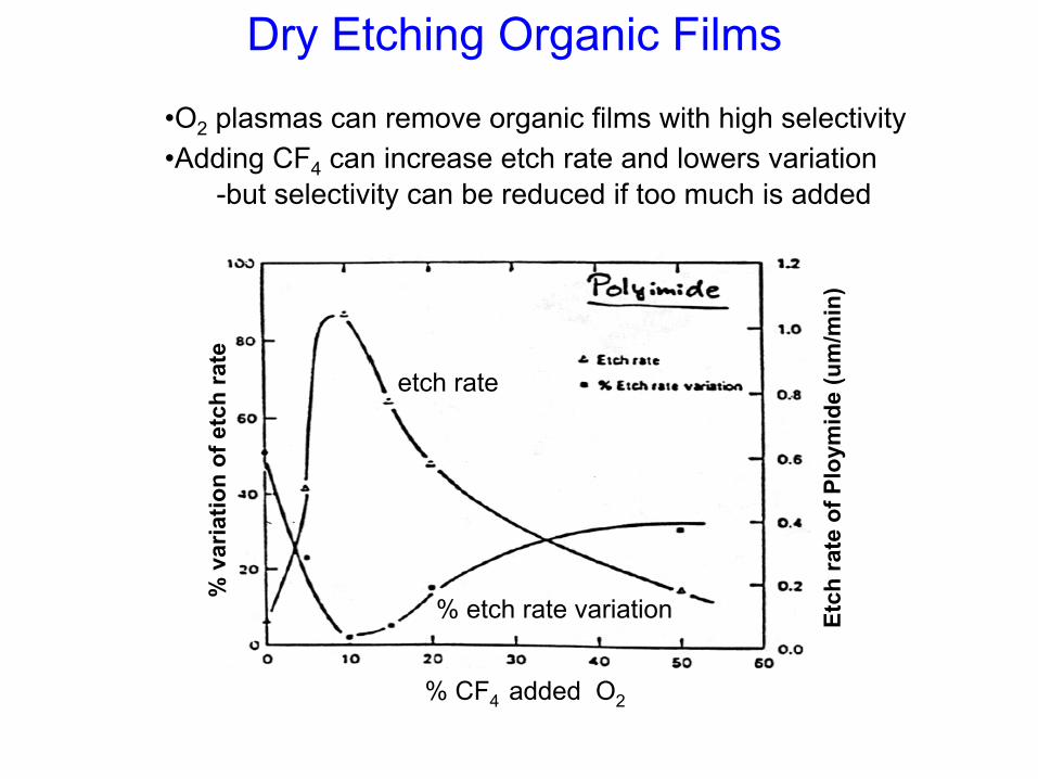
Dry Etching Organic Films
•O2 plasmas can remove organic films with high selectivity•Adding CF4 can increase etch rate and lowers variation
-but selectivity can be reduced if too much is added
Etch
rate
of P
loym
ide
(um
/min
)
% v
aria
tion
of e
tch
rate
etch rate
% etch rate variation
% CF4 added O2
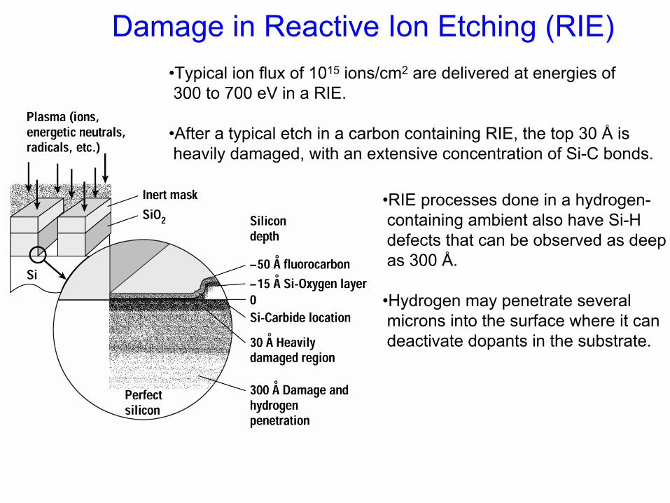
Damage in Reactive Ion Etching (RIE)•Typical ion flux of 1015 ions/cm2 are delivered at energies of 300 to 700 eV in a RIE.
•After a typical etch in a carbon containing RIE, the top 30 Å is heavily damaged, with an extensive concentration of Si-C bonds.
•RIE processes done in a hydrogen-containing ambient also have Si-H defects that can be observed as deepas 300 Å.
•Hydrogen may penetrate several microns into the surface where it candeactivate dopants in the substrate.