Embed Size (px)
Citation preview

DEE 1050 Computer OrganizationLecture 8: Storage, networks, and other
peripherals
Dr. Tian-Sheuan [email protected]. Electronics EngineeringNational Chiao-Tung University
Dept. Electronics Engineering,N
ational Chiao T
ung University

1DEE 1050 Lecture 1: Introduction
Institute of Electronics,National C
hiao Tung U
niversity
Outline
• Disk Storage and Dependability
DEE 1050 Lecture 1: Introduction
Institute of Electronics,National C
hiao Tung U
niversity
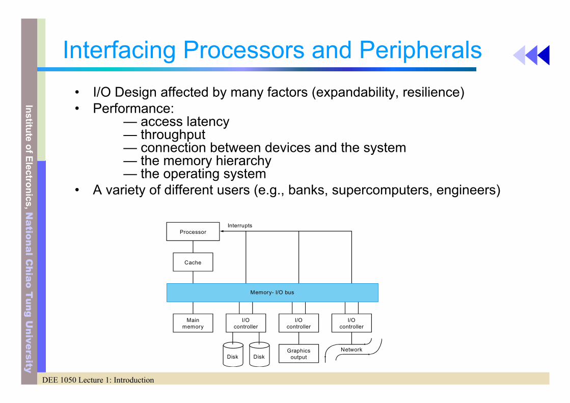
Interfacing Processors and Peripherals• I/O Design affected by many factors (expandability, resilience)• Performance:
— access latency — throughput— connection between devices and the system— the memory hierarchy— the operating system
• A variety of different users (e.g., banks, supercomputers, engineers)
Disk Disk
Processor
Cache
Memory- I/O bus
Mainmemory
I/Ocontroller
I/Ocontroller
I/Ocontroller
Graphicsoutput
Network
Interrupts

DEE 1050 Lecture 1: Introduction
Institute of Electronics,National C
hiao Tung U
niversity
I/O Devices
• Very diverse devices— behavior (i.e., input vs. output)— partner (who is at the other end?)— data rate

DEE 1050 Lecture 1: Introduction
Institute of Electronics,National C
hiao Tung U
niversity
I/O Example: Disk Drives•
• To access data:— seek: position head over the proper track (3 to 14 ms. avg.)— rotational latency: wait for desired sector (.5 / RPM)— transfer: grab the data (one or more sectors) 30 to 80 MB/sec
Platter
Track
Platters
Sectors
Tracks

5DEE 1050 Lecture 1: Introduction
Institute of Electronics,National C
hiao Tung U
niversity
Dependability
• Two system states– Service accomplishment
• Reliability– Measure of time to failure from a reference point– MTTF: mean time to failure
– Service interruption• MTTR: mean time to repair
– MTBF: MTTR+ MTTF, mean time between failure
• Availability– Measure of the service accomplishment with respect to the
alternation between the two states of accomplishment and interruption
– Availability = MTTF /( MTTF + MTTR)

6DEE 1050 Lecture 1: Introduction
Institute of Electronics,National C
hiao Tung U
niversity
MTTF
• To increase MTTF– Fault avoidance
• Prevent fault occurrence by construction
– Fault tolerance• Use redundancy to allow the service to comply with the service
specification despite faults occurring, which applies primarily to hardware faults
– Fault forecasting• Predict the presence and creation of faults, which applies to
hardware and software faults

7DEE 1050 Lecture 1: Introduction
Institute of Electronics,National C
hiao Tung U
niversity
RAID
• In 1987, – Patterson, Gibson and Katz at the University of California Berkeley,
published a paper entitled "A Case for Redundant Arrays of Inexpensive Disks (RAID)"
• The basic idea of RAID– To combine multiple small, inexpensive disk drives into an array
of disk drives which yields performance exceeding that of a Single Large Expensive Drive (SLED).
– Additionally, this array of drives appears to the computer as a single logical storage unit or drive.
• Mean Time Between Failure (MTBF) of the array– = MTBF of an individual drive / number of drives in the array– Because of this, the MTBF of an array of drives would be too low
for many application requirements. However, disk arrays can be made fault-tolerant by redundantly storing information in various ways

8DEE 1050 Lecture 1: Introduction
Institute of Electronics,National C
hiao Tung U
niversity
RAID
• RAID: redundant arrays of inexpensive disks• Why small inexpensive disks
– Many small disk has better read performance– Advantages in cost, power and floor space
• Why redundancy– May more smaller disks has lower reliability than a few
large disks

9DEE 1050 Lecture 1: Introduction
Institute of Electronics,National C
hiao Tung U
niversity
What I/O Performance Crisis?
• Existing huge gap in performance– 1000X disk/DRAM– Gap is increasing due to Moore’s law
• Cache-ineffective applications stress hierarchy– Video, data mining, digital library
• Remember “Amdahl’s law”

10DEE 1050 Lecture 1: Introduction
Institute of Electronics,National C
hiao Tung U
niversity
Introduction to RAID
• RAID: Redundant Array of Inexpensive Disks. – RAID is the organization of multiple disks into a large, high
performance logical disk.
• Basic technique: Data striping– Disk arrays stripe data across multiple disks and access them in
parallel to achieve:
– Higher data transfer rates on large data accesses and – Higher I/O rates on small data accesses. – Data striping also results in uniform load balancing across all of
the disks, eliminating hot spots that otherwise saturate a smallnumber of disks, while the majority of disks sit idle.

11DEE 1050 Lecture 1: Introduction
Institute of Electronics,National C
hiao Tung U
niversity
But....
• Large disk arrays, however are highly vulnerable to disk failures. – A disk array with a hundred disks is a hundred times
more likely to fail than a single disk. An MTTF (mean-time-to-failure) 500,000 hours for a single disk implies an MTTF of 500,000/100 i.e. 5000 hours for a disk array with a hundred disks.

12DEE 1050 Lecture 1: Introduction
Institute of Electronics,National C
hiao Tung U
niversity
So.... • The solution to the problem of lower reliability in disk arrays is to
improve the availability of the system. – This can be achieved by employing redundancy in the form of error-
correcting codes to tolerate disk failures. A redundant disk array can now retain data for much longer time than an unprotected single disk.
Do not confuse between reliability and availability. • Reliability
– is how well a system can work without any failures in its components. If there is a failure, the system was not reliable.
• Availability – is how well a system can work in times of a failure. If a system is able to
work even in the presence of a failure of one or more system components, the system is said to be available.
• Redundancy improves the availability of a system, but cannot improve the reliability. Reliability can only be increased by improving manufacturing technologies or using lesser individual components in a system.

13DEE 1050 Lecture 1: Introduction
Institute of Electronics,National C
hiao Tung U
niversity
Disadvantages due to Redundancy
• Bad write performance due extra writes– Every time there is a write operation, there is a change
of data. This change also, has to be reflected in the disks storing redundant information. This worsens the performance of writes in redundant disk arrays significantly compared to the performance of writes in non redundant disk arrays.
• Redundant information consistency– Also, keeping the redundant information consistent in
the presence of concurrent I/O operation and the possibility of system crashes can be difficult.

14DEE 1050 Lecture 1: Introduction
Institute of Electronics,National C
hiao Tung U
niversity
The Need for RAID
• Two keywords: Redundant and Array
• Array:– An array of multiple disks accessed in parallel will give greater
throughput than a single disk.
• Redundant– Redundant data on multiple disks provides fault tolerance. – You can still run your system when you replace a crashed disk
• Performance gain– true parallel accesses on multiple drives

15DEE 1050 Lecture 1: Introduction
Institute of Electronics,National C
hiao Tung U
niversity
To create an optimal cost-effective RAID
• 3 goals– Maximize the number of disks being accessed in
parallel. – Minimize the amount of disk space being used for
redundant data. – Minimize the overhead required to achieve the above
goals.

16DEE 1050 Lecture 1: Introduction
Institute of Electronics,National C
hiao Tung U
niversity
Data striping and Redundancy
• 2 important concepts to be understood in the design and implementation of disk arrays: – Data striping, for improved performance.– Redundancy for improved reliability.

17DEE 1050 Lecture 1: Introduction
Institute of Electronics,National C
hiao Tung U
niversity
Data Striping• Data striping
– transparently distributes data over multiple disks to make them appear as a single fast, large disk. Striping improves aggregate I/O performance by allowing multiple I/Os to be serviced in parallel.
Benefit for parallelism • Multiple, independent requests
– Multiple, independent requests can be serviced in parallel by separate disks. This decreases the queueing time seen by I/O requests.
• Single, multiple block requests– Single, multiple block requests can be serviced by multiple disks
acting in co-ordination. – This increases the effective transfer rate seen by a single request.
The performance benefits increase with the number of disks in the array. Unfortunately, a large number of disks lowers the overallreliability of the disk array.

18DEE 1050 Lecture 1: Introduction
Institute of Electronics,National C
hiao Tung U
niversity
RAID classification• based on 2 features:
– 1. the granularity of data interleaving and– 2. how to compute and store redundant data across the disk array.
Data interleaving• fine grained
– Fine grained disk arrays conceptually interleave data in relatively small units so that all I/O requests, regardless of their size, access all of the disks in the disk array.
– This results in very high data transfer rate for all I/O requests but has the disadvantages that only one logical I/O request can be in service at any given time and all disks must waste time positioning for every request.
• coarse grained – Coarse grained disk arrays interleave data in relatively large units so that
small I/O requests need access only a small number of disks while large requests can access all the disks in the disk array.
– This allows multiple small requests to be serviced simultaneously while still allowing large requests to see the higher transfer rates afforded by using multiple disks.

19DEE 1050 Lecture 1: Introduction
Institute of Electronics,National C
hiao Tung U
niversity
RedundancyThe incorporation of redundancy in disk arrays brings up two
problems: • 1. how to compute the redundant information.
– Most redundant disks arrays today use parity, though some use Hamming or Reed-Solomon codes.
• 2. how to distribute of the redundant information across the disk array. 2 different schemes: – Schemes that concentrate redundant information on a small
number of disks. – Schemes that distribute redundant information uniformly across
all of the disks.
– Such schemes is to avoid hot spots and other load balancing problems suffered by schemes that do not uniformly distribute redundant information.
20DEE 1050 Lecture 1: Introduction
Institute of Electronics,National C
hiao Tung U
niversity
RAID Classification
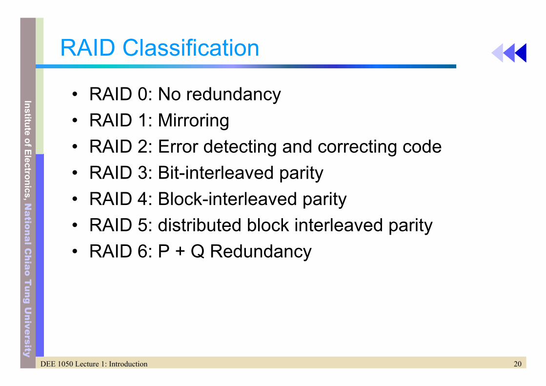
• RAID 0: No redundancy• RAID 1: Mirroring• RAID 2: Error detecting and correcting code• RAID 3: Bit-interleaved parity• RAID 4: Block-interleaved parity• RAID 5: distributed block interleaved parity• RAID 6: P + Q Redundancy

21DEE 1050 Lecture 1: Introduction
Institute of Electronics,National C
hiao Tung U
niversity
RAID

22DEE 1050 Lecture 1: Introduction
Institute of Electronics,National C
hiao Tung U
niversity
RAID

23DEE 1050 Lecture 1: Introduction
Institute of Electronics,National C
hiao Tung U
niversity
RAID 0: No redundancy
• Striping– Simply spreading data over multiple disk
• Redundancy– No
• Target application– performance and capacity, rather than reliability, are
the primary concerns – Supercomputing application– Video editing systems

24DEE 1050 Lecture 1: Introduction
Institute of Electronics,National C
hiao Tung U
niversity
RAID 1: Mirroring
• Striping– No
• Redundancy– Two copies of the information,
• twice as many disks as a non-redundant disk array – Whenever data are written to one disk, those data are also written
to redundant disk• What if one disk fails
– Just goes to the “mirrors” and read its contents• Cost
– Most expensive solution• Target application
– used in database applications where availability and transaction time are more important than storage efficiency

25DEE 1050 Lecture 1: Introduction
Institute of Electronics,National C
hiao Tung U
niversity
RAID 2: Error detecting and correcting code
• Striping– interleaved
• Redundancy– Memory style ECC (don’t know which bit to correct)
• Borrows an error detection and correction scheme used from memories (Hamming code)
• However, disk controllers can easily identify which disk has failed => RAID 3
– Extra multiple parity disks• Target application
– Not used anymore, Partly due to the disk has its own ECC
26DEE 1050 Lecture 1: Introduction
Institute of Electronics,National C
hiao Tung U
niversity
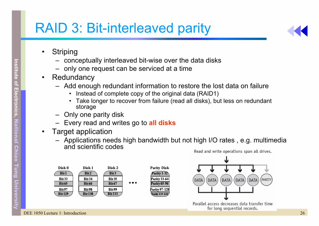
RAID 3: Bit-interleaved parity• Striping
– conceptually interleaved bit-wise over the data disks – only one request can be serviced at a time
• Redundancy– Add enough redundant information to restore the lost data on failure
• Instead of complete copy of the original data (RAID1)• Take longer to recover from failure (read all disks), but less on redundant
storage– Only one parity disk– Every read and writes go to all disks
• Target application– Applications needs high bandwidth but not high I/O rates , e.g. multimedia
and scientific codes

27DEE 1050 Lecture 1: Introduction
Institute of Electronics,National C
hiao Tung U
niversity
RAID 4: Block-interleaved parity• Striping
– interleaved• Redundancy
– Same ratio of data disks and check disk as RAID3– But parity is stored as blocks an associated with a set of data blocks– Key insight to reduce the overhead
• Parity is simply a sum of information• By watching which bit change when we write the new information, we need
only change the corresponding bits on the parity disks• Fig. 8-7
– Better for small read (just one disk) and small writes (less read)– Drawback: parity disk is the bottleneck (updated on every write)
28DEE 1050 Lecture 1: Introduction
Institute of Electronics,National C
hiao Tung U
niversity
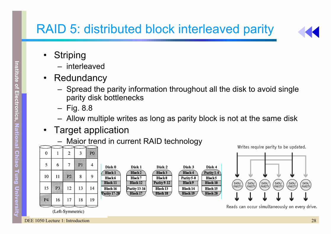
RAID 5: distributed block interleaved parity
• Striping– interleaved
• Redundancy– Spread the parity information throughout all the disk to avoid single
parity disk bottlenecks– Fig. 8.8– Allow multiple writes as long as parity block is not at the same disk
• Target application– Major trend in current RAID technology

29DEE 1050 Lecture 1: Introduction
Institute of Electronics,National C
hiao Tung U
niversity
RAID 6: P + Q Redundancy
• Previous parity based scheme protect against a single self-identifying failure
• What if more than one fault– One more check disk to the data and original check
disk

30DEE 1050 Lecture 1: Introduction
Institute of Electronics,National C
hiao Tung U
niversity
RAID Summary
• Major trend– RAID-1 and RAID-5 (80%)
• Weakness: repair– 1. Data should be available during repair– Hot-swapping
• Replace a hardware component while the system is running• RAID redundancy allow continue operation• Both physical and electrical design support this
– 2. Another failure could occur during repair period. Minimize the repair period
– Standby spares• Reserved hardware that can immediately replace the failed one• Data can be reconstructed immediately upon discovery of the failure
– 3. Disk failure could be related due to poor cooling or shaking– 4. human error to replace the good disk instead of the bad one,
leading to an unrecoverable disk failure