Embed Size (px)
Citation preview

Complex Sensors • We already discussed:
active versus passive sensors
reflective optosensors
reflectance
break-beam
various detectable object features
shaft encoding
speed and position
quadrature shaft encoding
modulated IR
IR communication
Today we are going to talk about ultrasonic and vision sensing.
Are those sensors active or passive?
Ultrasonic
Distance
Sensing

Ultrasonic Distance Sensing • As we mentioned before, ultrasound sensing is based on the time-of-
flight principle.
• The emitter produces a sonar "chirp" of sound, which travels away
from the source, and, if it encounters barriers, reflects from them and
returns to the receiver (microphone).
• The amount of time it takes for the sound beam to come back is
tracked:
– starting the timer when the "chirp" is produced, and
– stopping the timer when the reflected sound returns
• Is used to compute the distance the sound traveled.
• This is possible (and quite easy) because we know how fast sound
travels; this is a constant, which varies slightly based on ambient
temperature.

Ultrasonic Distance Sensing
• Ultrasonic burst, or ―chirp,‖ travels out to
an object, and is reflected back into a
receiver circuit, which is tuned to detect the
specific frequency of sound emitted by the
transmitter.
• By measuring the elapsed time from when
the chirp is emitted to when the echo is
received, the distance may be calculated. In
normal room temperature, sound travels
about 0.89 milliseconds per foot
• Since the sound has to go out to the object
and then back to the receiver, 1.78 msec of
elapsed time corresponds to an object at one
foot’s distance from each of the emitter and
receiver
• So the distance to the target object (in
feet) is the time it takes for a chirp to make
a round trip (in msec) divided by 1.78
Ultrasonic Ranging
Ultrasonic ranging
Measures the actual time-of-flight for a
sonar ―chirp‖ to bounce of a target and
return to the sensor
Greater accuracy than with IR sensing
Ultrasonic Distance Sensing
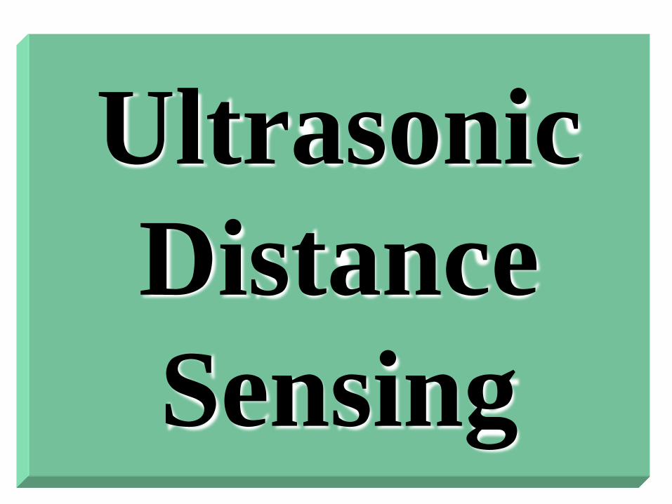
• Ultrasonic burst, or ―chirp,‖
• travels out to an object,
• reflected back into a receiver
circuit, ( tuned to detect the
specific frequency of sound)
• Measures time-of-flight of ―chirp‖
• sound travels about 0.89 ms per
foot / 1.78 ms for round trip
• distance to the target object (in
feet) is the time it takes for a chirp to
make a round trip (in msec) divided
by 1.78
•Greater accuracy than with IR
•Bats use radar-like form of
ultrasonic ranging to navigate as
they fly
(copyright Prentice Hall 2001)

Ultrasonic Distance Sensing (cont)
• At room temperature, sound travels at 1.12 feet per
millisecond.
– Another way to put it that sound travels at 0.89
milliseconds per foot. This is a useful constant to
remember.
• The process of finding one's location based on
sonar is called echolocation.
• The inspiration for ultrasound sensing comes from nature;
– bats use ultrasound instead of vision (this makes sense;
– they live in very dark caves where vision would be largely
useless).
Ultrasonic Distance Sensing
• Bat sonars are extremely sophisticated compared to
artificial sonars;
• They involve numerous different frequencies, used
for:
– finding even the tiniest fast-flying prey, and
– for avoiding hundreds of other bats, and
– communicating for finding mates.

Specular Reflection • A major disadvantage of ultrasound sensing is its
susceptibility to specular reflection
– specular reflection means reflection from the outer surface of the
object
• The sonar sensing principle is based on the sound wave
reflecting from surfaces and returning to the receiver.
• The direction of reflection depends on:
– the incident angle of the sound beam
– the surface.
• Thus, important to remember that the sound wave will not
necessarily bounce off the surface and "come right back."

Specular Reflection
• The smaller the angle, the higher the probability that the
sound will merely "graze" the surface and bounce off,
– thus not returning to the emitter,
– in turn generating a false long/far-away reading.
• This is often called specular reflection, because smooth
surfaces, with specular properties, tend to aggravate this
reflection problem.
• Coarse surfaces produce more irregular reflections, some
of which are more likely to return to the emitter.

• For example, in our experiments with PSUBOT, we used sonar sensors, and we
have lined one part of the test area with wooden panel.
• It has much better sonar reflectance properties than the very smooth wall behind
it. Big glass windows are also a trouble.
• In summary, long sonar readings can be very inaccurate, as they may result from
false rather than accurate reflections.
• This must be taken into account when programming robots, or a robot may produce
very undesirable and unsafe behavior.
• For example, a robot approaching a wall at a steep angle may not see the wall at all,
and collide with it!
• Nonetheless, sonar sensors have been successfully used for very sophisticated
robotics applications, including terrain and indoor mapping
• They remain a very popular sensor choice in mobile robotics.
• We use them in PSUBOT and PEOPLEBOT.
Specular Reflection

• Food for thought:
– what happens when multiple
robots need to work together
and all have sonar sensors?

Polaroid sensors • The first commercial ultrasonic sensor was produced by Polaroid.
• They used them to automatically measure the distance to the nearest
object (presumably which is being photographed).
• These simple Polaroid sensors still remain the most popular off-the-
shelf sonars
• They come with a processor board that deals with the analog
electronics.
• Their standard properties include:
– 32-foot range
– 30-degree beam width
– sensitivity to specular reflection
– shortest distance return

Polaroid sensors
• Polaroid sensors can be combined into phased arrays to
create more sophisticated and more accurate sensors.
• One can find ultrasound used in a variety of other
applications; the best known one is ranging in submarines.
– The sonars there have much more focused and have longer-range
beams.
• Simpler and more mundane applications involve:
– automated "tape-measures",
– height measures,
– burglar alarms,
– etc.
• Sections covered above: Martin: 6.3.
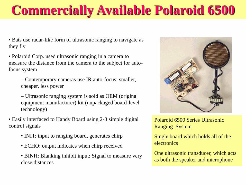
• Bats use radar-like form of ultrasonic ranging to navigate as
they fly
• Polaroid Corp. used ultrasonic ranging in a camera to
measure the distance from the camera to the subject for auto-
focus system
– Contemporary cameras use IR auto-focus: smaller,
cheaper, less power
– Ultrasonic ranging system is sold as OEM (original
equipment manufacturer) kit (unpackaged board-level
technology)
• Easily interfaced to Handy Board using 2-3 simple digital
control signals
• INIT: input to ranging board, generates chirp
• ECHO: output indicates when chirp received
• BINH: Blanking inhibit input: Signal to measure very
close distances
Commercially Available Polaroid 6500
Polaroid 6500 Series Ultrasonic
Ranging System
Single board which holds all of the
electronics
One ultrasonic transducer, which acts
as both the speaker and microphone
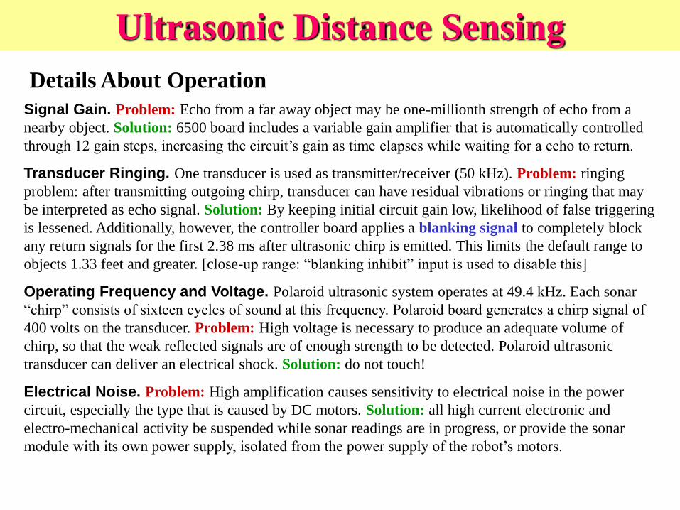
Signal Gain. Problem: Echo from a far away object may be one-millionth strength of echo from a
nearby object. Solution: 6500 board includes a variable gain amplifier that is automatically controlled
through 12 gain steps, increasing the circuit’s gain as time elapses while waiting for a echo to return.
Transducer Ringing. One transducer is used as transmitter/receiver (50 kHz). Problem: ringing
problem: after transmitting outgoing chirp, transducer can have residual vibrations or ringing that may
be interpreted as echo signal. Solution: By keeping initial circuit gain low, likelihood of false triggering
is lessened. Additionally, however, the controller board applies a blanking signal to completely block
any return signals for the first 2.38 ms after ultrasonic chirp is emitted. This limits the default range to
objects 1.33 feet and greater. [close-up range: ―blanking inhibit‖ input is used to disable this]
Operating Frequency and Voltage. Polaroid ultrasonic system operates at 49.4 kHz. Each sonar
―chirp‖ consists of sixteen cycles of sound at this frequency. Polaroid board generates a chirp signal of
400 volts on the transducer. Problem: High voltage is necessary to produce an adequate volume of
chirp, so that the weak reflected signals are of enough strength to be detected. Polaroid ultrasonic
transducer can deliver an electrical shock. Solution: do not touch!
Electrical Noise. Problem: High amplification causes sensitivity to electrical noise in the power
circuit, especially the type that is caused by DC motors. Solution: all high current electronic and
electro-mechanical activity be suspended while sonar readings are in progress, or provide the sonar
module with its own power supply, isolated from the power supply of the robot’s motors.
Details About Operation
Ultrasonic Distance Sensing
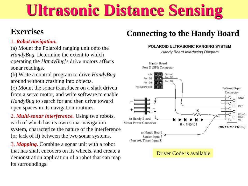
Exercises 1. Robot navigation.
(a) Mount the Polaroid ranging unit onto the
HandyBug. Determine the extent to which
operating the HandyBug’s drive motors affects
sonar readings.
(b) Write a control program to drive HandyBug
around without crashing into objects.
(c) Mount the sonar transducer on a shaft driven
from a servo motor, and write software to enable
HandyBug to search for and then drive toward
open spaces in its navigation routines.
2. Multi-sonar interference. Using two robots,
each of which has its own sonar navigation
system, characterize the nature of the interference
(or lack of it) between the two sonar systems.
3. Mapping. Combine a sonar unit with a robot
that has shaft encoders on its wheels, and create a
demonstration application of a robot that can map
its surroundings.
Connecting to the Handy Board
Ultrasonic Distance Sensing
Driver Code is available

Design Objectives
• General Description: – An autonomous vehicle capable of avoiding objects in order to sense
movement or infra-red sources for the security of a building.
• Core Functions: – Ultrasonic Sensing
– Infrared Sensing
– Independent drive motors for steering
• Possible Additional Items – Multiple Operating Modes
– Better Alarm Generation
Roaming Security Watchdog
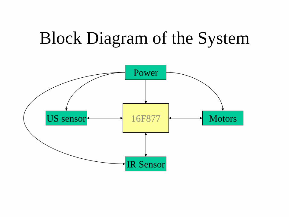
Block Diagram of the System
16F877 Motors US sensor
IR Sensor
Power

Why we chose the PIC16F877
• Fast clock (20MHz)
• 33 I/O lines
• Ease of programming (BASIC)
• Onboard RAM and Flash Memory Size
• Static Flash RAM
• Versatility in design possibilities
• Cost

PICMicro 16F877 Overview
• RISC Archetecture (35 commands)
• 20MHz clock input
• 200ns instruction cycle
• 8k of Flash Program Memory
• 14 Interrupts
• 3 Individual Timers
• 8 channel, 10 bit A/D converter
• Parallel Port optional input
• Brown Out Detection
• I2C Communications
• Serial Communications
• 33 I/O Lines
• LOW COST (approx $7)

Software Design Method
• Individual Blocks (from initial diagram) functioning
independently.
• Pre-determined variable names so that the software code can be
pre-written to incorporate the blocks designed independently.
• Program logic into the drive mechanism.
• Steer the vehicle to avoid obstacles in real time using the
Ultrasonic Sensors.
• Detect motion using the IR sensors and send an alarm.
• Monitor and remember current coordinates to map the room in
memory for faster autonomous roaming. (Optional Learning)
• After detection of an intruder, decide a course of action.
Possible Mechanical System
• Wooden Chassis
– Plywood (approx. foot by foot)
• Tank treads
– With two motors: one operating on each side.
– Skid steering
• DC Motor
– Bi-directional
– Continuous
• The application of power causes the shaft to rotate continually.
– Servo Motor: Combines continuous motor with ―feedback loop‖ to ensure accurate positioning of the motor.
Motor Specifications
• DC Motor
– Low-voltage variety: operating range at 1.5 to 12 V
– 50% < operating range < 130%
• Speed
– 0.5 ft per second
• Current Draw
– The current draw of a motor increases in proportion to the load on the motor shaft
• Torque
• Gears

POWER SYSTEMS
THE ISSUE:
How will a single 12V motorcycle battery properly supply:
•Micro controllers and digital parts that require a very
constant +5V supply
•Analog circuitry requiring anywhere from 512V, as well
as ±10V supplies
•DC Motors that require fairly large current draws with
bipolar operation
Motorcycle Battery
(12V, ~5A)
- +

POWER OVERVIEW THE SOLUTION:

DC MOTOR CONTROL
The DC Motors will be operated both forward and backward,
so both positive and negative voltages must be applied
•At the moment, all we have to work with is a single 12V
supply
•An H-Bridge converter can be used to provide anywhere
from –12V to 12V at the output by varying the duty cycle
•By switching between two duty cycles, we can run the
motors forward and backward
-1
-0.8
-0.6
-0.4
-0.2
0
0.2
0.4
0.6
0.8
1
0 0.2 0.4 0.6 0.8 1
D
M(D
)

H-BRIDGE CONVERTER
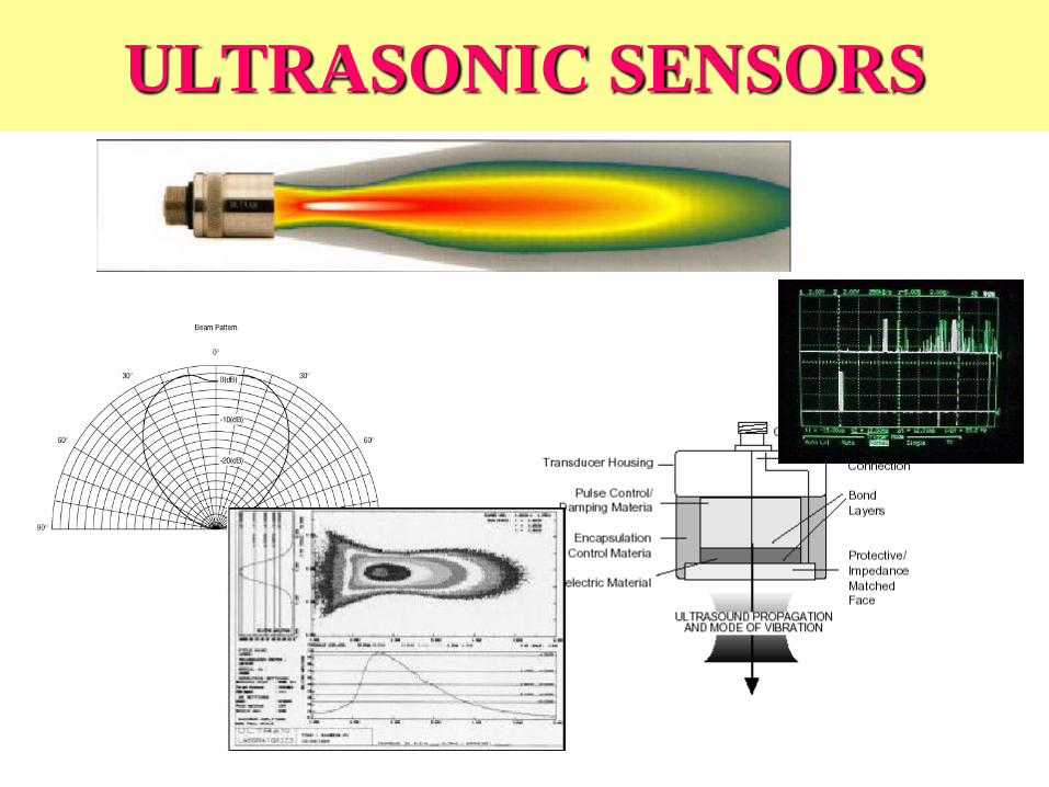
ULTRASONIC SENSORS

PIC
40 kHz rectangular pulse
Received pulse
Ultrasonic
Transmit
Ultrasonic
Receive
SU
RFA
CE
ULTRASONIC DISTANCE DETECTION REVIEW
To determine distance, the PIC will have a routine to
determine the time duration between the sent pulse and the
return pulse. From there, distance is determined by the
simple relationship:
d = vsound · t

CREATING THE 40kHz PULSE
•In order for the detectors to work well, the transmitters must stay
quite close to the 40kHz notch in the receiver’s sensitivity.
•Three remaining possibilities for the 40kHz pulse generation:
•Op Amp Oscillator Circuit—a simple op amp is used in
combination with resistors and capacitors
•10MHz Crystal with 8 bit counting—the 10Mhz clock is used
in combination with a divide by 256 counter to create a stable
39.06kHz oscillator
•Interrupt Driven Counter on PIC—uses on-board counters on
PIC to generate continuous 40kHz CMOS square wave
DISTRIBUTING THE 40kHZ PULSE
•Rather than create a 40kHz generator for each transmitter, a switching
solution is used
•Only one transmitter needs the 40kHz signal at any given time
•Simple SPST switches can be used to distribute the signal to the
appropriate transmitter
•The PIC will control which transmitter to fire via two
addressing lines into a de-multiplexor, which will then switch
the appropriate SPST to allow the signal to pass

ULTRASONIC TRANSMIT CIRCUIT
•The ultrasonic receiver is designed to begin vibrating when there is
a 40kHz wave incident upon it.
•Although the reflected sound wave will not be identical to the
transmitted wave in shape and especially magnitude, the
frequency should be the same
What about the Doppler effect?
ULTRASONIC RECEIVER REVIEW
THE DOPPLER EFFECT

We probably won’t have our Roaming Security Watchdog going that
fast…
But the fact remains that we are dealing
with a source-receiver pair in motion, so the
Doppler effect does occur according to the
following equation:
As it turns out, the effect of Doppler shifting is negligible, even if our
vehicle moved twice as fast as it currently does…
THE DOPPLER EFFECT
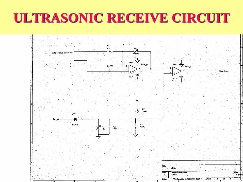
ULTRASONIC RECEIVE CIRCUIT

PYROELECTRIC SENSOR
• sensors detecting infrared
heat
• Glolab RE200B ($4)
• crystalline material
• Frensel Lens ($4)
– Human IR wavelength range
8-14μm
• Chassis placement
Figure 1

• Output Characteristics
– 20mV
RE200B Amp. Comp. PIC
Backup
Sound sensor
PYROELECTRIC SENSOR
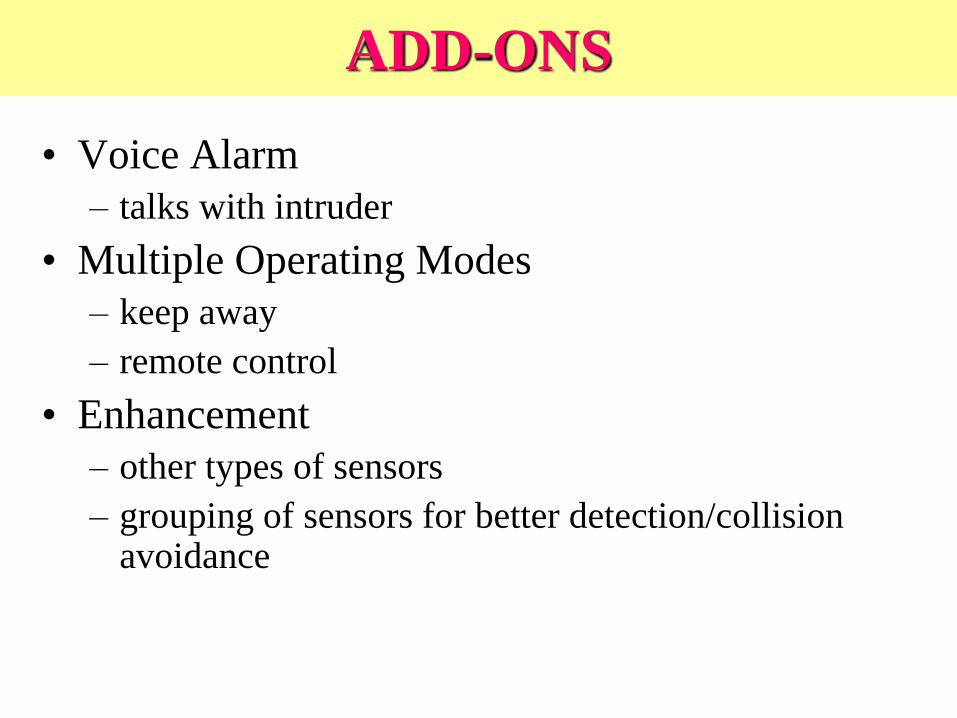
ADD-ONS
• Voice Alarm
– talks with intruder
• Multiple Operating Modes
– keep away
– remote control
• Enhancement
– other types of sensors
– grouping of sensors for better detection/collision avoidance

DEMO
• Have your robot demonstrate the following movements using inverse kinematics, closed-loop encoder monitoring, and proportional control
– Line: 36 inches forward, 180 degree turn, 36 inches forward
– Square: 36 inches forward, 90 degree turn, 36 inches forward, 90 degree turn, 36 inches forward, 90 degree turn, 36 inches forward, 90 degree turn
– Triangle: 16 inches backward, -90 degree turn, 12 inches backward, -307 degrees, 20 inches backward, 217 degrees
• Lab 7: Understanding Sonar

Magellan Sonar Display

Sonar Beam • Distance is not a point distance
• Sonar beam has angular ―spread‖
(about 30 degree dispersion in
Polaroid module)
• Closest point of object is
somewhere within that arc
• Need multiple readings to
disambiguate – but readings take
time; tradeoffs
?
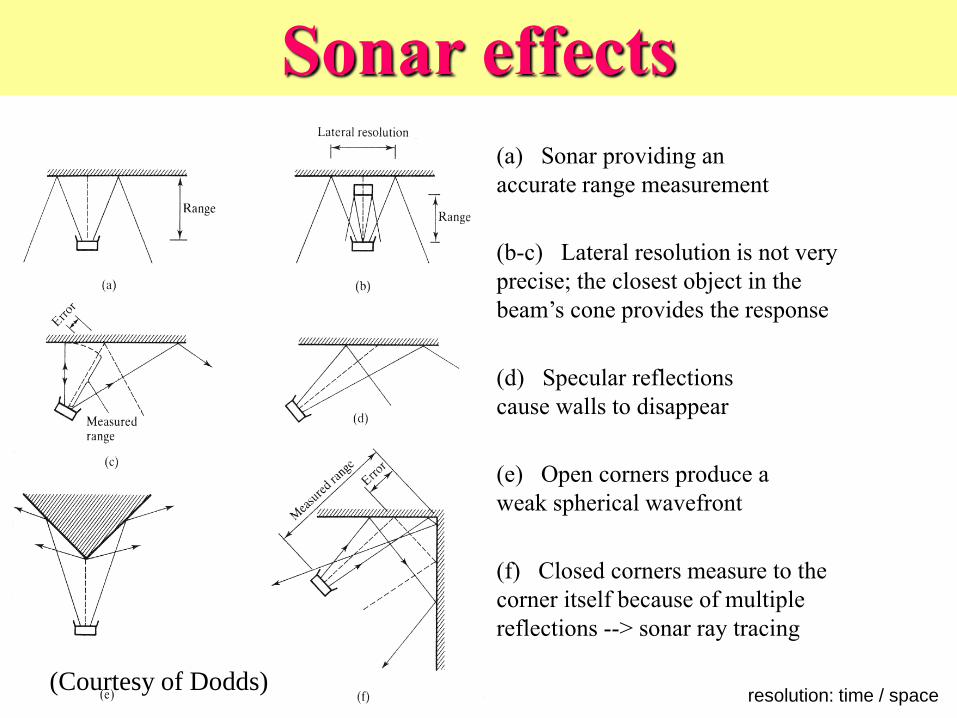
Sonar effects
resolution: time / space
(d) Specular reflections
cause walls to disappear
(e) Open corners produce a
weak spherical wavefront
(f) Closed corners measure to the
corner itself because of multiple
reflections --> sonar ray tracing
(a) Sonar providing an
accurate range measurement
(b-c) Lateral resolution is not very
precise; the closest object in the
beam’s cone provides the response
(Courtesy of Dodds)

Other Sources of Error • reflectance of surface to
sound – signal strength,
non-specular reflections,
signal absorption,
approach angle
• corners
• Crosstalk/ghost images –
reflected sound received
from wrong transmitter
• change in speed of sound
due to temperature and
humidity

Sonar modeling initial time response
spatial response
blanking time
accumulated
responses
cone width
(Courtesy of Dodds)

Sonar vs. IR
• Both can be used as distance sensors
• Sonar is more commonly used
• Sonar cannot easily be used between 1 and
6 inches from obstacle

Attaching and
programming
sonar
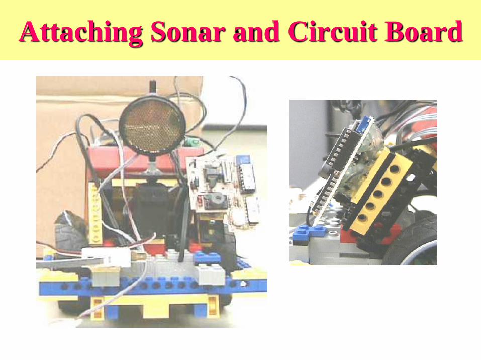
Attaching Sonar and Circuit Board
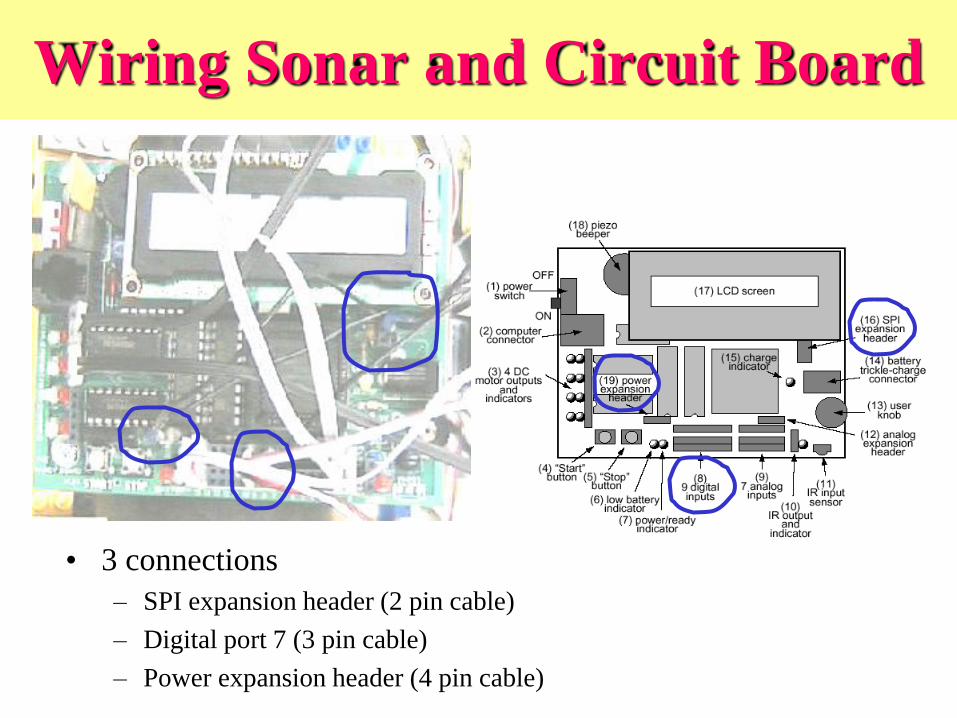
Wiring Sonar and Circuit Board
• 3 connections
– SPI expansion header (2 pin cable)
– Digital port 7 (3 pin cable)
– Power expansion header (4 pin cable)

http://lcs.www.media.mit.edu/groups/el/project
s/handy-board/software/sonar.html
(Middle of second column,
blue closest to LCD)
(Blue
on
left)
Wiring Sonar and Circuit Board
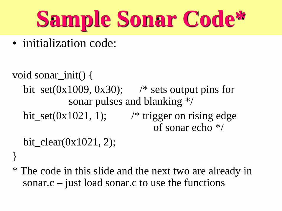
Sample Sonar Code* • initialization code:
void sonar_init() {
bit_set(0x1009, 0x30); /* sets output pins for sonar pulses and blanking */
bit_set(0x1021, 1); /* trigger on rising edge of sonar echo */
bit_clear(0x1021, 2);
}
* The code in this slide and the next two are already in sonar.c – just load sonar.c to use the functions

Grabbing a Sonar Sample
int sonar_sample() {
int start_time;
poke(0x1023, 1); /* clear tic3 flag */
start_time= peekword(0x100e); /* capture start time */
bit_set(0x1008, 0x20); /* trigger pulse */
while (!(peek(0x1000) & 0x1)) { /* wait until receive echo */
if ((peekword(0x100e) - start_time) < 0) {
/* if too much time has elapsed, abort */
bit_clear(0x1008, 0x20);
return -1;
}
defer(); /* let others run while waiting */
}
bit_clear(0x1008, 0x20); /* clear pulse trigger */
return peekword(0x1014) - start_time; /* tic3 has time of echo */
}
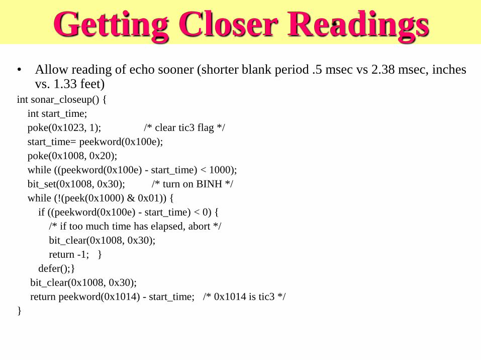
Getting Closer Readings • Allow reading of echo sooner (shorter blank period .5 msec vs 2.38 msec, inches
vs. 1.33 feet) int sonar_closeup() {
int start_time;
poke(0x1023, 1); /* clear tic3 flag */
start_time= peekword(0x100e);
poke(0x1008, 0x20);
while ((peekword(0x100e) - start_time) < 1000);
bit_set(0x1008, 0x30); /* turn on BINH */
while (!(peek(0x1000) & 0x01)) {
if ((peekword(0x100e) - start_time) < 0) {
/* if too much time has elapsed, abort */
bit_clear(0x1008, 0x30);
return -1; }
defer();}
bit_clear(0x1008, 0x30);
return peekword(0x1014) - start_time; /* 0x1014 is tic3 */
}

Using the Sonar Functions
void sonar_display()
{
sonar_init();
while (1) {
int result;
result= sonar_sample();
if (result != -1) printf("%d\n", result);
else printf("*******\n");
msleep(50L); /* need to pause between readings */
}
}

Converting from Sonar Reading
to Distance
• Distance (ft) = ((counts/2000) * 1.1)/2
– (or 2.75 * (counts/10000))
• Sound travels 1.1 feet per millisec
• (In average air conditions)
• .5 microsecs per timer count (10000 counts = 5 millisecs)
• Example
– 10000 counts
– 5 millisecs * 1.1 ft/millisec = 5.5 feet
– 5.5 ft/2 for round trip time = 2.75 feet for 10000 timer counts
- ((10000/2000) * 1.1)/2 = 2.75
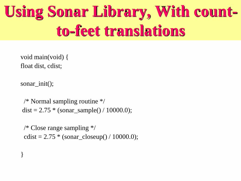
Using Sonar Library, With count-
to-feet translations
void main(void) {
float dist, cdist;
sonar_init();
/* Normal sampling routine */
dist = 2.75 * (sonar_sample() / 10000.0);
/* Close range sampling */
cdist = 2.75 * (sonar_closeup() / 10000.0);
}

Today
• Understanding sonar
• Attaching and programming sonar
• Servo motors and programming
• Sonar for obstacle avoidance
• Serial communication review
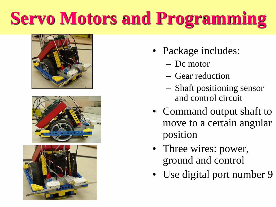
Servo Motors and Programming
• Package includes:
– Dc motor
– Gear reduction
– Shaft positioning sensor and control circuit
• Command output shaft to move to a certain angular position
• Three wires: power, ground and control
• Use digital port number 9

Servomotors
“direct” position control -- in
response to the width of a
regularly sent pulse
modified to run continuously

Servo Motor Output Commands • Need to load servo motor library --
servo.icb and servo.c (done by default)
• void servo_on() void servo_off()
– Enables/Disables servo output waveform.
• int servo(int period)
– Sets length of servo control pulse. Minimum allowable value is 1400 (i.e., 700 sec); maximum is 4860. Function return value is actual period set by driver software.
• int servo_rad(float angle)
– Sets servo angle in radians.
• int servo_deg(float angle)
– Sets servo angle in degrees.
• For our specific servos, you must set the MIN_SERVO_WAVETIME variable to 600, and the MAX_SERVO_WAVETIME variable to 4400 for a proper mapping between degrees/radians and pulses.

Servo Turret
• Attach forward-facing
servo motor to robot
• Can use to mount
various sensors that
can actively scan a
scene

Sonar for
obstacle
avoidance
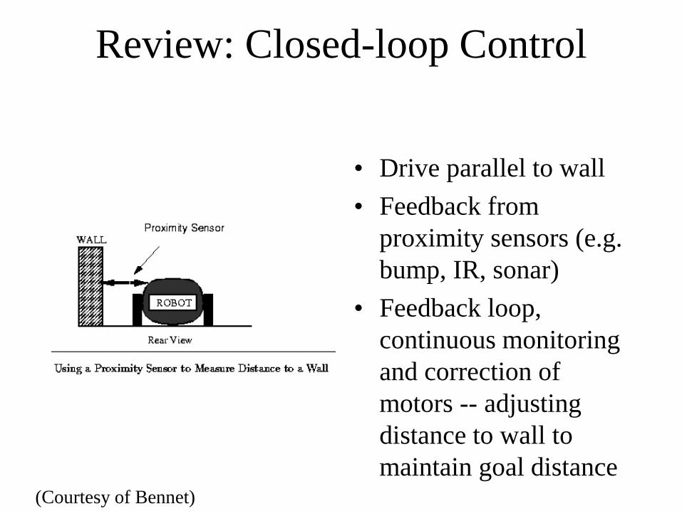
Review: Closed-loop Control
• Drive parallel to wall
• Feedback from
proximity sensors (e.g.
bump, IR, sonar)
• Feedback loop,
continuous monitoring
and correction of
motors -- adjusting
distance to wall to
maintain goal distance (Courtesy of Bennet)
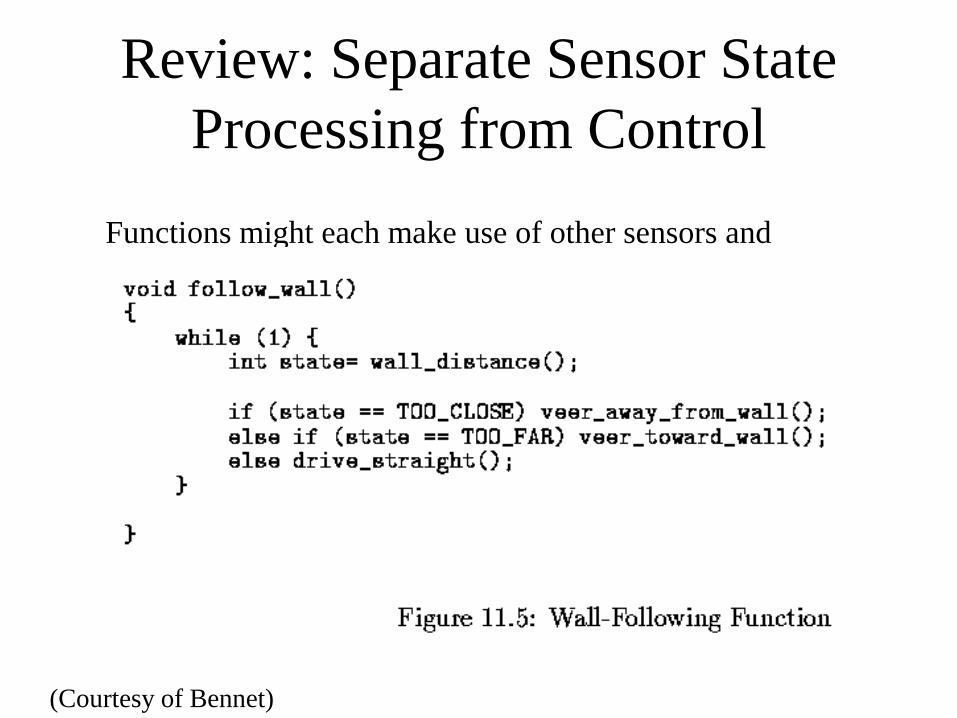
Review: Separate Sensor State
Processing from Control
Functions might each make use of other sensors and
functions – need to decide how to implement each
(Courtesy of Bennet)
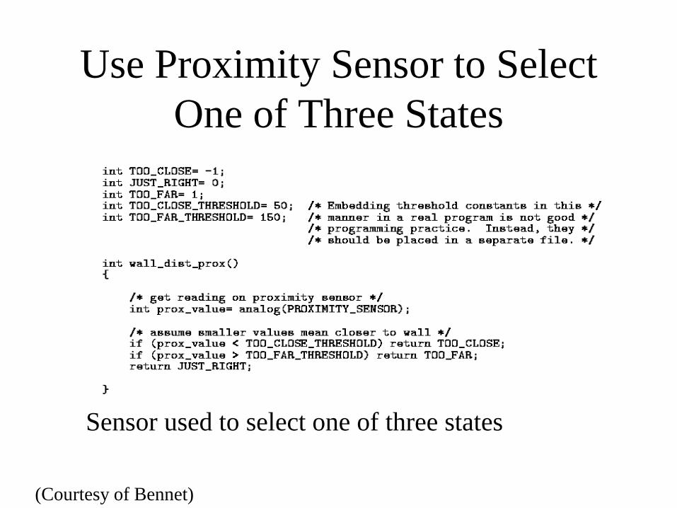
Use Proximity Sensor to Select
One of Three States
Sensor used to select one of three states
(Courtesy of Bennet)

Obstacle Avoidance and Tracking
Using Sonar
• Have continuously running
task update obstacle state:
– Left, right, both, neither
• If one obstacle detected use
closed-loop control to keep
it away from robot
• If two obstacles detected
– Estimate distance and try to
pass in-between with closed-
loop control, if possible

Review: Simple Processing Using Single
Threshold
•Robot ground sensor can be in one of two states:
•State A: Over line
•State B: Over floor
•Compare sensor reading with setpoint value
•If less than this threshold set variable to indicate robot is in State A
•Otherwise, set variable to indicate State B
• What to use as setpoint threshold?
• midpoint between floor value and line value
•E.g. 10 when aimed at the floor, and 50 when aimed at the line
choose 30 as setpoint threshold

Review: Two Thresholds for Hysteresis
•Problem with single threshold –
variances in sensor readings
• Bump on floor may spike
the readings
• Shiny spots on line may
reflect as well as the floor,
dropping the sensor readings
up into the range of the floor
• Solution: two setpoints can be
used
– Imposes hysteresis on the
interpretation of sensor
values, i.e., prior state of
system (on/off line) affects
system’s movement into a
new state
Line Following performance run :
Setpoint =20
int LINE_SETPOINT= 35;
int FLOOR_SETPOINT= 10;
void waituntil_on_the_line() {
while (line_sensor() < LINE_SETPOINT);
}
void waituntil_off_the_line() {
while (line_sensor() > FLOOR_SETPOINT);
}
(copyright Prentice Hall 2001)
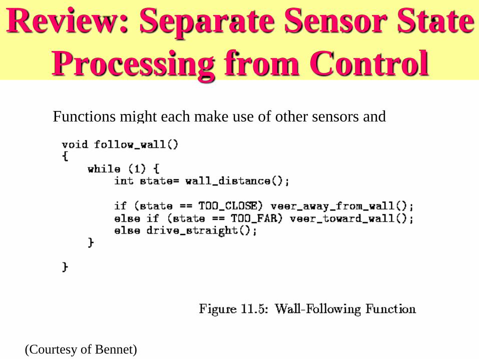
Review: Separate Sensor State
Processing from Control
Functions might each make use of other sensors and
functions – need to decide how to implement each
(Courtesy of Bennet)

• Michael Walker
• Jason Jones
• Charlie Hwang
• Mitch Tu
• Maja Mataric
• Fred Martin
Understanding sonar and servos
http://plan.mcs.drexel.edu/courses/
robotlab/labs/lab07.pdf