Embed Size (px)
Citation preview
Lecture 7
Object Oriented Design
Outline
What is UML and why we use UML?
How to use UML diagrams to design software system?
What UML Modeling tools we use today?
What is UML and Why we use UML?
UML → “Unified Modeling Language” Language: express idea, not a methodology It is a industry-standard graphical language for specifying,
visualizing, constructing, and documenting the artifacts of software systems
Modeling: Describing a software system at a high level of abstraction
Unified: UML has become aObject Management Group (OMG): www.omg.org world standard
Simplifies the complex process of software design
What is UML and Why we use UML?
Why we use UML? Use graphical notation: more clearly than natural language
(imprecise) and code (too detailed).
Help acquire an overall view of a system.
UML is not dependent on any one language or technology.
UML moves us from fragmentation to standardization.

What is UML and Why we use UML?
1997: UML 1.0, 1.1
1996: UML 0.9 & 0.91
1995: Unified Method 0.8
Other methods
Booch ‘91
Booch ‘93 OMT - 2
OMT - 1
Year Version 2003: UML 2.0
2001: UML 1.4
1999: UML 1.3

How to use UML diagrams to design software system?
• Types of UML Diagrams: Use Case Diagram Class Diagram Sequence Diagram Collaboration Diagram State Diagram Activity diagram Component diagram Deployment diagram Package diagram
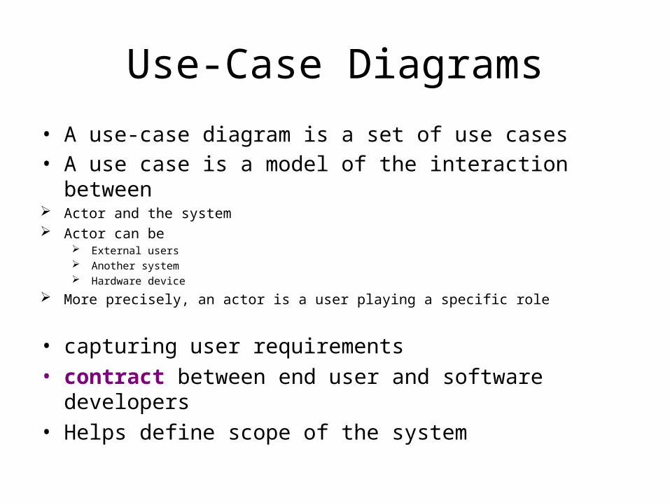
Use-Case Diagrams
• A use-case diagram is a set of use cases• A use case is a model of the interaction between Actor and the system Actor can be
External users Another system Hardware device
More precisely, an actor is a user playing a specific role
• capturing user requirements• contract between end user and software developers• Helps define scope of the system
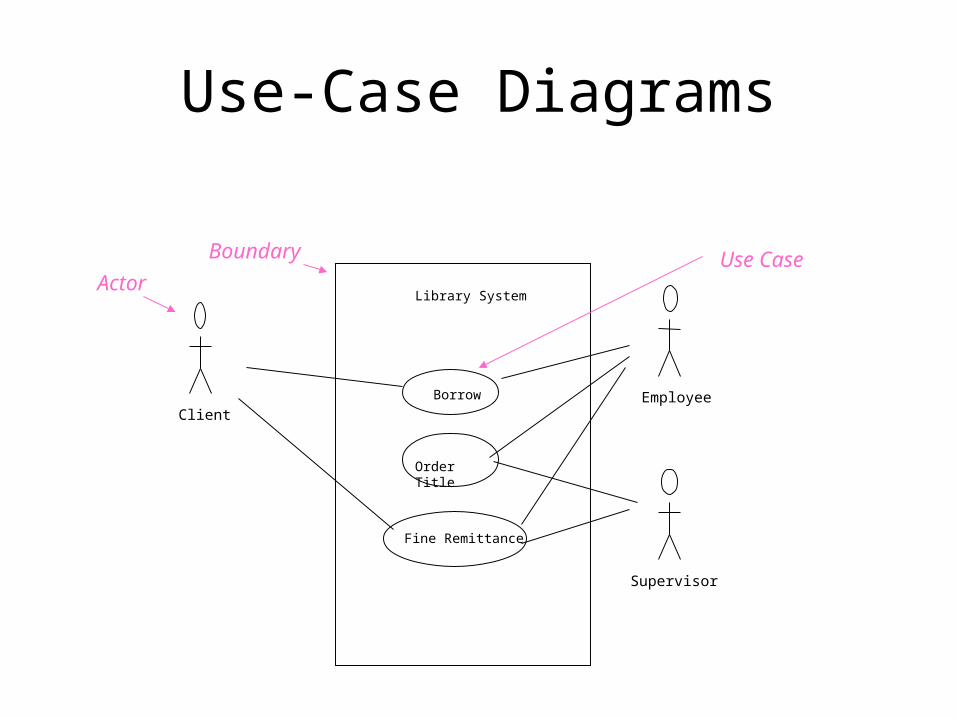
Use-Case Diagrams
Library System
Borrow
Order Title
Fine Remittance
ClientEmployee
Supervisor
Boundary
ActorUse Case
Use-Case Diagrams
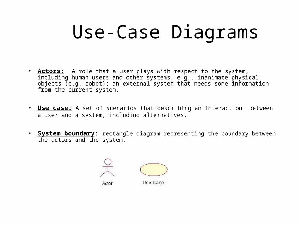
• Actors: A role that a user plays with respect to the system, including human users and other systems. e.g., inanimate physical objects (e.g. robot); an external system that needs some information from the current system.
• Use case: A set of scenarios that describing an interaction between a user and a system, including alternatives.
• System boundary: rectangle diagram representing the boundary between the actors and the system.
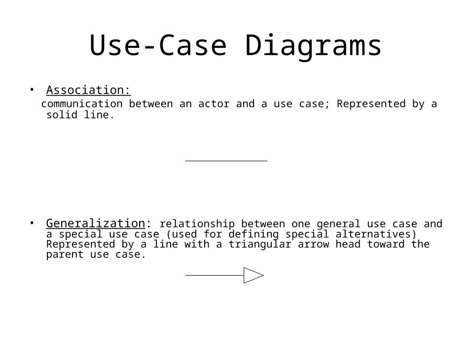
Use-Case Diagrams• Association: communication between an actor and a use case; Represented by a solid line.
• Generalization: relationship between one general use case and a special use case (used for defining special alternatives) Represented by a line with a triangular arrow head toward the parent use case.
Use-Case Diagrams
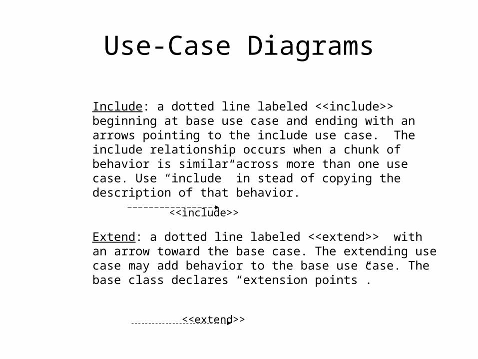
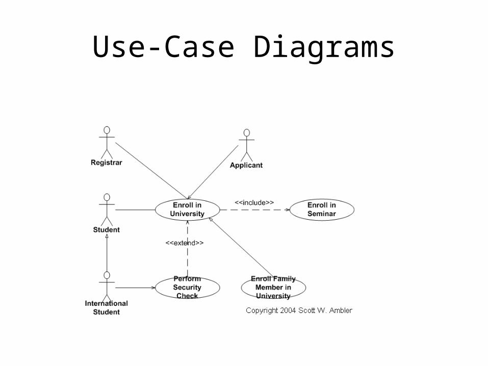
Extend: a dotted line labeled <<extend>> with an arrow toward the base case. The extending use case may add behavior to the base use case. The base class declares “extension points”.
<<extend>>
Include: a dotted line labeled <<include>> beginning at base use case and ending with an arrows pointing to the include use case. The include relationship occurs when a chunk of behavior is similar across more than one use case. Use “include” in stead of copying the description of that behavior.
<<include>>
Use-Case Diagrams
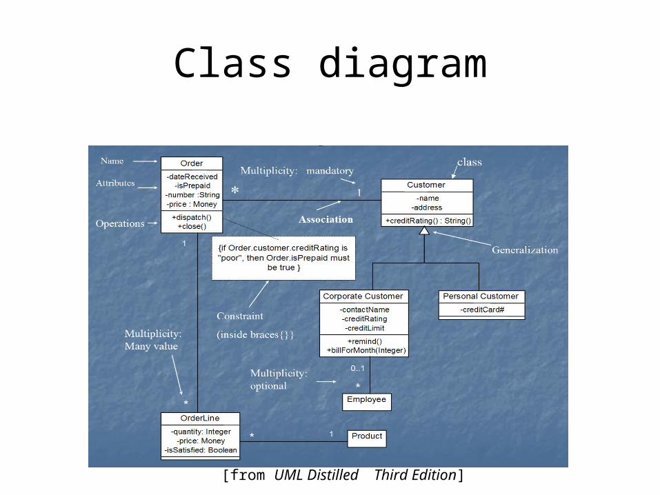
Class diagram
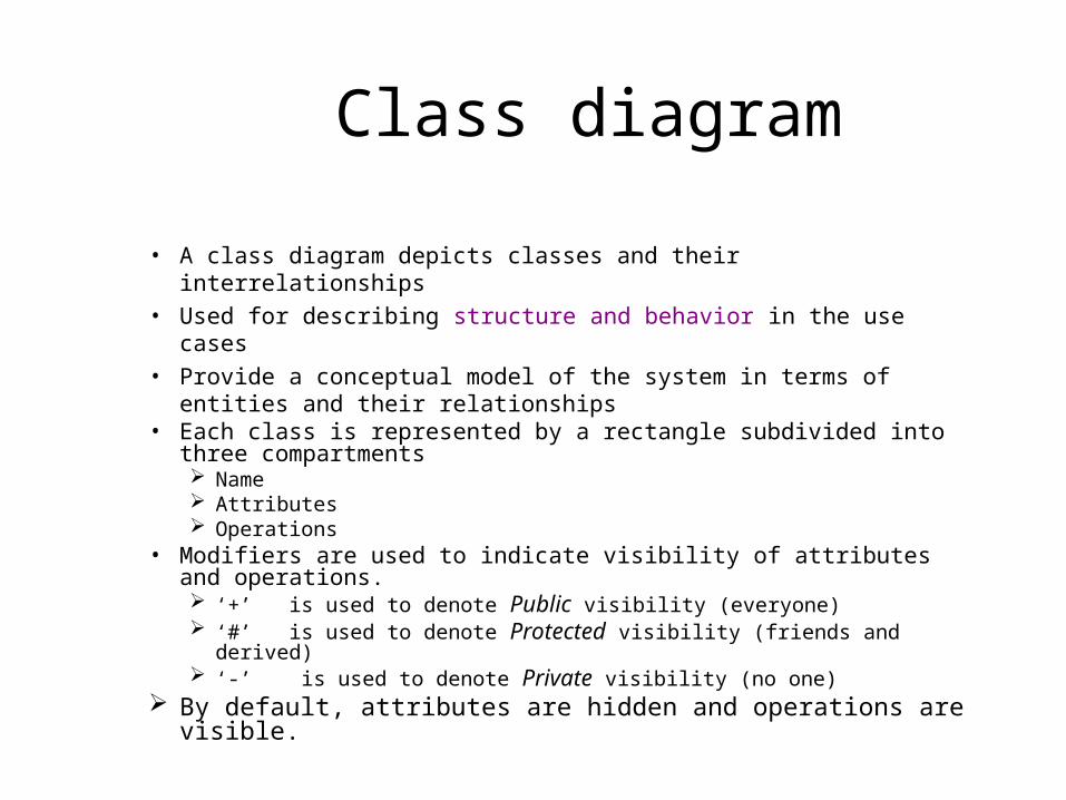
• A class diagram depicts classes and their interrelationships• Used for describing structure and behavior in the use cases• Provide a conceptual model of the system in terms of
entities and their relationships• Each class is represented by a rectangle subdivided into three
compartments Name Attributes Operations
• Modifiers are used to indicate visibility of attributes and operations. ‘+’ is used to denote Public visibility (everyone) ‘#’ is used to denote Protected visibility (friends and derived) ‘-’ is used to denote Private visibility (no one)
By default, attributes are hidden and operations are visible.
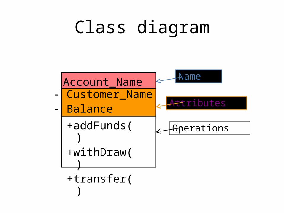
Class diagram
Account_Name- Customer_Name- Balance
+addFunds( )+withDraw( )+transfer( )
Name
Attributes
Operations

OO Relationships
• There are two kinds of Relationships Generalization (parent-child relationship) Association (student enrolls in course)
• Associations can be further classified as Aggregation Composition
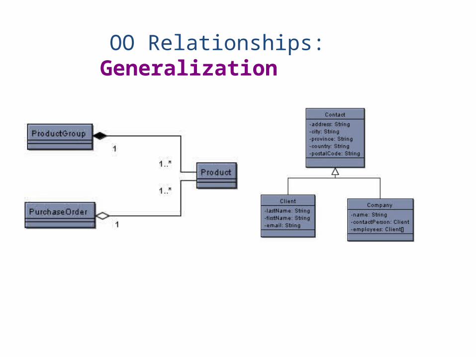
OO Relationships: Generalization
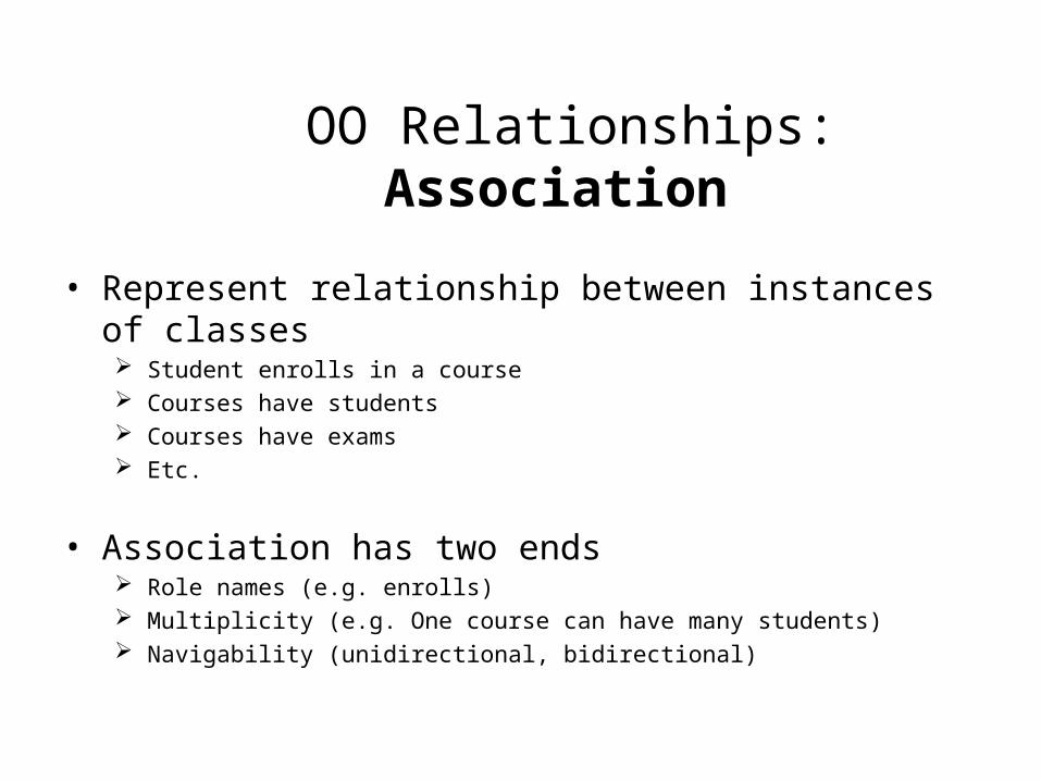
• Represent relationship between instances of classes Student enrolls in a course Courses have students Courses have exams Etc.
• Association has two ends Role names (e.g. enrolls) Multiplicity (e.g. One course can have many students) Navigability (unidirectional, bidirectional)
OO Relationships: Association

Association: Multiplicity and Roles
University Person
1
0..1
*
*
Multiplicity
Symbol Meaning
1 One and only one
0..1 Zero or one
M..N From M to N (natural language)
* From zero to any positive integer
0..* From zero to any positive integer
1..* From one to any positive integer
teacheremployer
Role
Role
“A given university groups many people; some act as students, others as teachers. A given student belongs to a single university; a given teacher may or may not be working for the university at a particular time.”
student
Class diagram
[from UML Distilled Third Edition]
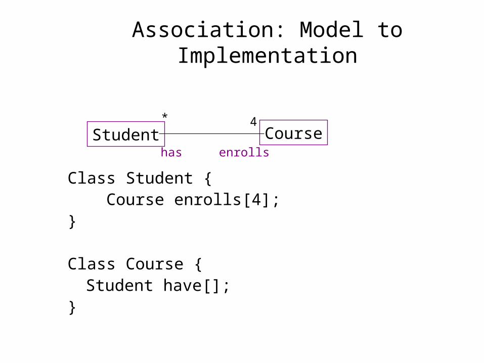
Association: Model to Implementation
Class Student { Course enrolls[4];}
Class Course {Student have[];
}
Student Courseenrollshas
* 4
Interaction Diagrams
• show how objects interact with one another
• UML supports two types of interaction diagrams Sequence diagramsCollaboration diagrams
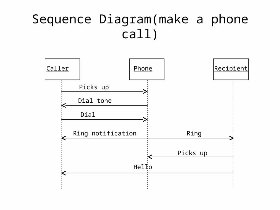
Sequence Diagram(make a phone call)
Caller Phone Recipient
Picks up
Dial tone
Dial
Ring notification Ring
Picks up
Hello

Sequence Diagram:Object interaction
Self-CallSelf-Call: A message that an Object sends to itself.
Condition: indicates when a message is sent. The message is sent only if the condition is true.
Iteration
Condition
A B
Synchronous
Asynchronous
Transmission delayed
Self-Call
[condition] remove()
*[for each] remove()
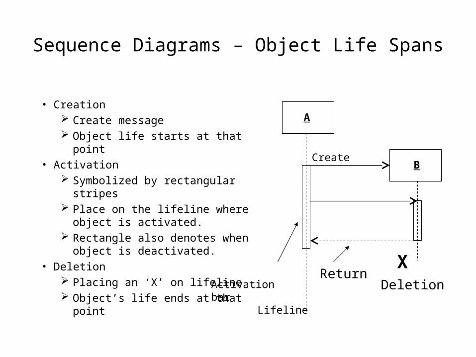
Sequence Diagrams – Object Life Spans
• Creation Create message Object life starts at that point
• Activation Symbolized by rectangular stripes Place on the lifeline where object is
activated. Rectangle also denotes when object
is deactivated.• Deletion
Placing an ‘X’ on lifeline Object’s life ends at that point
Activation bar
A
BCreate
XDeletion
Return
Lifeline
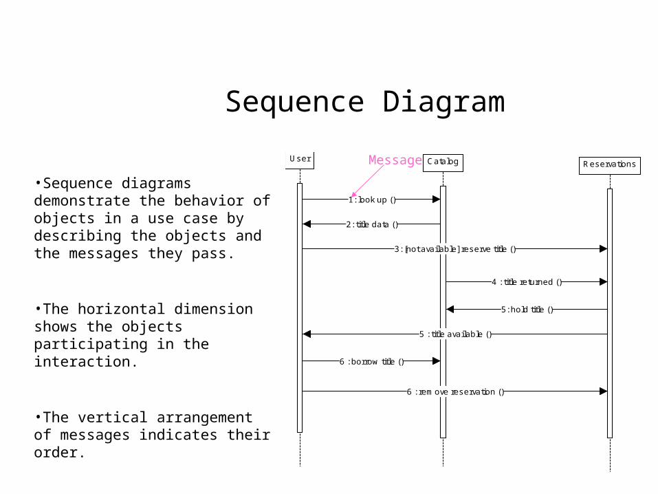
Sequence Diagram
User Catalog Reservations
1: look up ()
2: title data ()
3: [not available] reserve title ()
4 : title returned ()
5: hold title ()
5 : title available ()
6 : borrow title ()
6 : rem ove reservation ()
•Sequence diagrams demonstrate the behavior of objects in a use case by describing the objects and the messages they pass.
•The horizontal dimension shows the objects participating in the interaction.
•The vertical arrangement of messages indicates their order.
•The labels may contain the seq. # to indicate concurrency.
Message

Interaction Diagrams: Collaboration diagrams
User
Catalog
Reservations
start
1: look up2: title data
3 : [not available] reserve title
4 : title returned
5 : hold title
6 : borrow title
6: remove reservation
5: title available
Collaboration diagrams are equivalent to sequence diagrams. All the features of sequence diagrams are equally applicable to collaboration diagrams
Use a sequence diagram when the transfer of information is the focus of attention
Use a collaboration diagram when concentrating on the classes
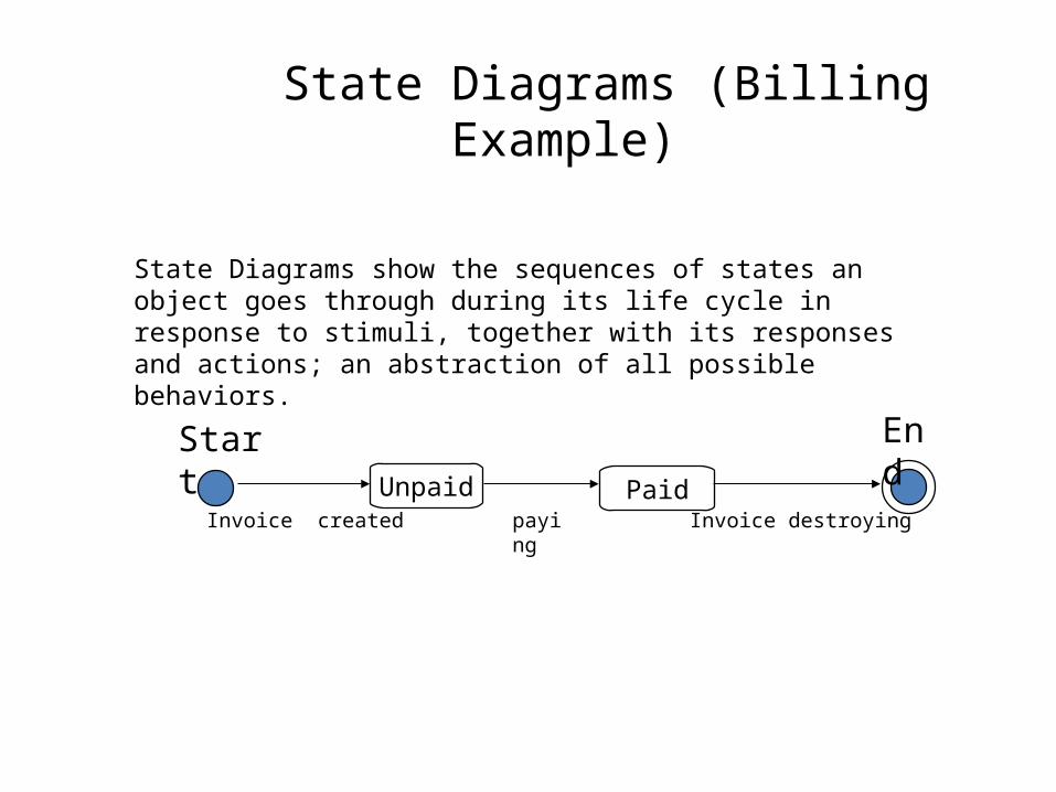
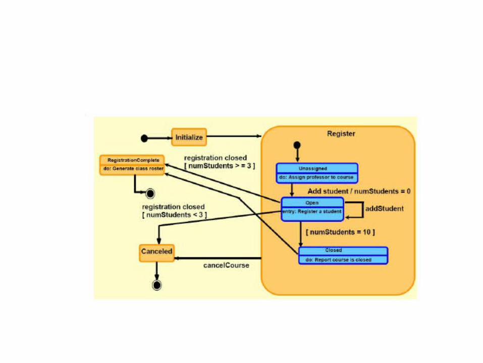
State Diagrams (Billing Example)
State Diagrams show the sequences of states an object goes through during its life cycle in response to stimuli, together with its responses and actions; an abstraction of all possible behaviors.
Unpaid
Start End
PaidInvoice created payin
gInvoice destroying
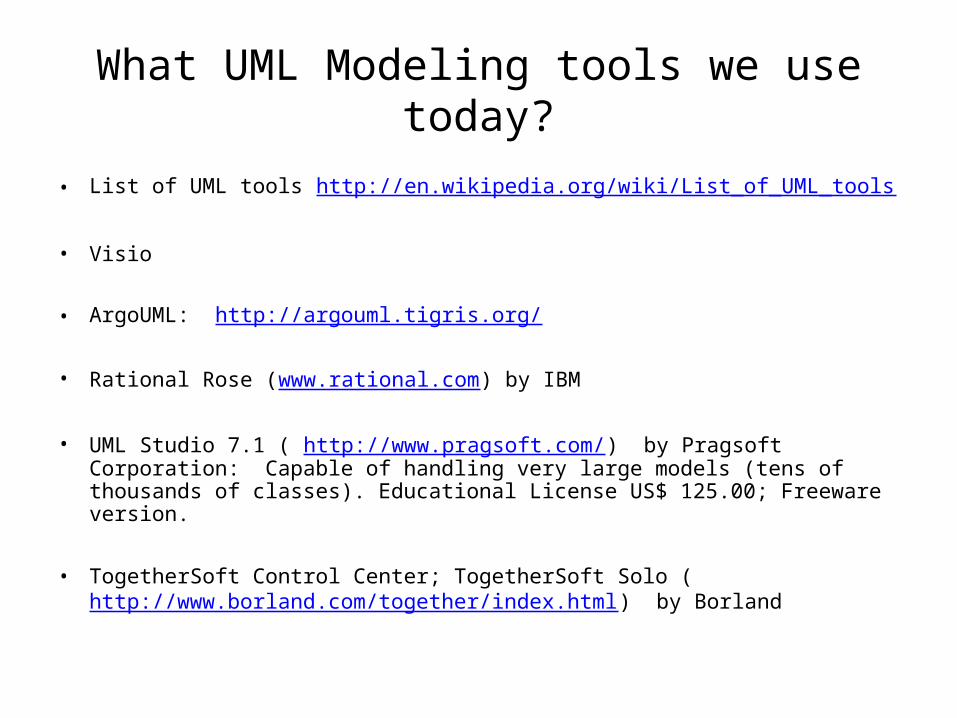
What UML Modeling tools we use today?
• List of UML tools http://en.wikipedia.org/wiki/List_of_UML_tools
• Visio
• ArgoUML: http://argouml.tigris.org/
• Rational Rose (www.rational.com) by IBM
• UML Studio 7.1 ( http://www.pragsoft.com/) by Pragsoft Corporation: Capable of handling very large models (tens of thousands of classes). Educational License US$ 125.00; Freeware version.
• TogetherSoft Control Center; TogetherSoft Solo (http://www.borland.com/together/index.html) by Borland
Conclusion
• UML is a standardized specification language for object modeling
• Several UML diagrams: use-case diagram: a number of use cases (use case models the interaction between
actors and software) Class diagram: a model of classes showing the static relationships among them
including association and generalization. Sequence diagram: shows the way objects interact with one another as messages
are passed between them. Dynamic model State diagram: shows states, events that cause transitions between states. Another
dynamic model reflecting the behavior of objects and how they react to specific event