Embed Size (px)
Citation preview

AMSS-MSc Prof. Kasim Al-Aubidy 1
Lecture (7)
Motion Detectors, Position,
and Level Measurements
Prof. Kasim M. Al-Aubidy
Philadelphia University-Jordan
AMSS-MSc Prof. Kasim Al-Aubidy 2
Introduction: The occupancy sensors detect the presence of people (and sometimes animals) in a
monitored area.
Motion detectors respond only to moving objects.
The differences between the two is that the occupancy sensors produce signals
whenever an object is stationary or not, while the motion detectors are selectively
sensitive to moving objects.
The following types of detectors are used for the occupancy and motion sensing:
Air pressure sensors: detect changes in air pressure resulted from opening doors
and windows
Capacitive detectors: detectors of human body capacitance
Acoustic detectors: detectors of sound produced by people
Photoelectric detectors : interruption of light beams by moving objects
Optoelectric detectors : detection of variations in illumination or optical contrast
in the protected area
AMSS-MSc Prof. Kasim Al-Aubidy 3
Detectors are used for the occupancy and motion sensing:
Pressure mat switches: pressure sensitive long strips used on floors beneath the
carpets to detect weight of an intruder
Stress detectors: strain gauges imbedded into floor beams, staircases, and other
structural components
Switch sensors: electrical contacts connected to doors and windows
Magnetic switches: a noncontact version of switch sensors
Vibration detectors: react to the vibration of walls or other building structures.
Also, may be attached to doors or windows to detect movements
Glass breakage detectors: sensors reacting to specific vibrations produced by
shattered glass
Infrared motion detectors: devices sensitive to heat waves emanated from warm
or cold moving objects
Microwave detectors: active sensors responsive to microwave electromagnetic
signals reflected from objects

AMSS-MSc Prof. Kasim Al-Aubidy 4
Detectors are used for the occupancy and motion sensing:
Ultrasonic detectors: devices similar to microwave detectors except that instead of
electromagnetic radiation, ultrasonic waves are used
Video motion detectors: a video equipment that compares a stationary image
stored in memory with the current image from a protected area
Video face recognition system: image analyzers that compare facial features with
database
Laser system detectors: similar to photoelectric detectors, except that they use
narrow light beams and combinations of reflectors
Tribo-electric detectors: sensors capable of detecting static electric charges
carried by moving objects

AMSS-MSc Prof. Kasim Al-Aubidy 5
Proximity Sensors:
– Mechanical
– Optical
– Inductive/Capacitive
Mechanical Proximity Switches:
Essentially a mechanical switch
On/off operation only; Two general modes
Normally Open (NO)
Normally Closed (NC)
Come in a wide variety of mechanical forms
When to Use Mechanical Proximity Switches:
Where physical contact is possible
Where definitive position is required
In operation-critical or safety-critical situations.
Where environment conditions preclude the use of optical or inductive sensors.

AMSS-MSc Prof. Kasim Al-Aubidy 6
Applications of Mechanical Proximity Switches:
Easy to integrate into machinery of all types
Requires contact
Range of voltages: DC 0-1000V, AC, etc.
Very robust (explosion proof if required)
Usually used as:
Limit switch
Presence/absence indicator
Door closed/open
AMSS-MSc Prof. Kasim Al-Aubidy 7
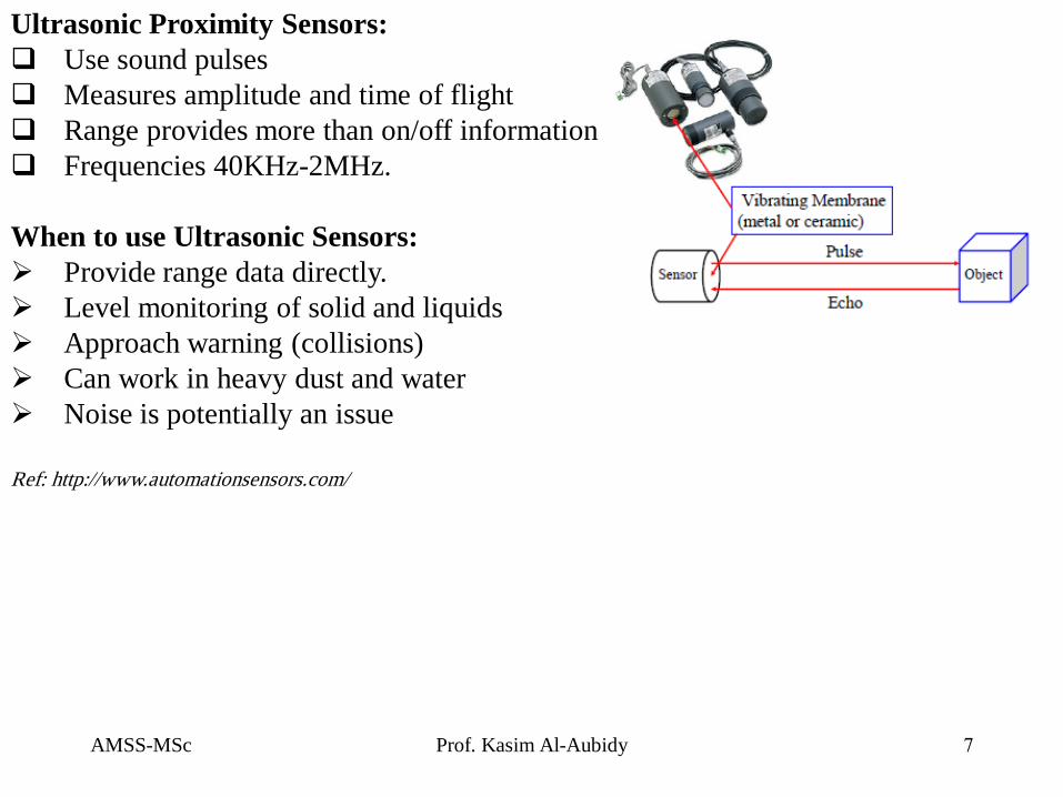
Ultrasonic Proximity Sensors:
Use sound pulses
Measures amplitude and time of flight
Range provides more than on/off information
Frequencies 40KHz-2MHz.
When to use Ultrasonic Sensors:
Provide range data directly.
Level monitoring of solid and liquids
Approach warning (collisions)
Can work in heavy dust and water
Noise is potentially an issue
Ref: http://www.automationsensors.com/

AMSS-MSc Prof. Kasim Al-Aubidy 8
Inductive and Capacitive Proximity Sensors:
• Inductive sensors use change in local magnetic field to detect presence of metal
Target.
• Capacitive Sensors use change in local capacitance caused by non-metallic objects
• Generally short ranges only
• Very robust and reliable

AMSS-MSc Prof. Kasim Al-Aubidy 9
Position Sensors:
Position sensors are essential elements in the mechatronics systems for control
purposes. There are three principle types:
1. Resistive sensors.
2. Capacitive sensors.
3. Inductive sensors.
4. Optical sensors.
1. Resistive Sensors: Potentiometers:
A potentiometer is a variable electrical resistance.
A length of resistance material has a voltage
applied over its ends.
A slider moves along it (either linear or rotary)
and picks off the voltage at its position or angle.
The tracks may be made from carbon , resistance
wire or piezo resistive material.
The wire wound type produces small step changes
in the output depending on how fine the wire is
and how closely it is coiled on the track.

AMSS-MSc Prof. Kasim Al-Aubidy 10
Potentiometers:
A position or displacement transducer may be built with a linear or rotary potentiometer.
The voltage across the wiper of a linear pot is
proportional to the displacement (d);
Problem: The wiper, when moving across the
winding, may make contact with either one or
two wires, thus resulting in uneven voltage
steps (then variable resolution). Therefore,
when a coil potentiometer with (N) turns is
used, only the average resolution (n) should
be considered:
n = 100/N%

AMSS-MSc Prof. Kasim Al-Aubidy 11
Example: Potentiometer sensor position system for Robot Arm

AMSS-MSc Prof. Kasim Al-Aubidy 12
2. Capacitive Sensors:
The ability of capacitive detectors to sense virtually all materials makes them an
attractive choice for many applications.
They are employed directly to gauge displacement and position and also as
building blocks in other sensors where displacements is produced by force,
pressure, temperature, etc.
The capacitance of a flat capacitor is inversely proportional to the distance between
the plates. The operating principle of a capacitive gauge , proximity , and position
sensors is based on either changing the geometry (i.e. a distance between the
capacitor plates), or capacitance variations in the presence of conductive or
dielectric materials.
Example: Assume that the central plate moves
downward by distance (x). This causes changes in
the respective capacitance values:
The amplitude of the output signals is

AMSS-MSc Prof. Kasim Al-Aubidy 13
3. Linear Variable Differential transformer ( LVDT):
It is made with one primary coil and two secondary coils. A
magnetic core slides in the tube and is attached to the
mechanism being monitored with a non magnetic stem (e.g.
brass).
A constant AC voltage is applied to the primary coil. This
induces a voltage in both secondary coils. When the core is
exactly in the middle, equal voltages are induced and when
connected as shown in the figure, they cancel each other out.
When the core moves, the voltage in one secondary coil grows
but reduces in the other. The result is an o/p voltage which
represents the position of the core.

AMSS-MSc Prof. Kasim Al-Aubidy 14
LVDT Principles:

AMSS-MSc Prof. Kasim Al-Aubidy 15
The o/p voltage is converted into DC with suitable
electronic circuit for phase detection. It is possible
to detect which direction the core moves and to
switch the DC voltage from plus to minus as the
core passes the centre position. These can be very
accurate and are widely used for gauging the
dimensions of machined components.

AMSS-MSc Prof. Kasim Al-Aubidy 16
LVDT Signal Conditioning:
It is connected to a synchronous
detector that rectifies the sine
wave and presents it at the output
as a DC signal.
The synchronous detector is
comprised of;
An analog multiplexer (MUX),
Zero-crossing detector, and
Output Amplifier.
The LVDT sensor output voltage
represents how far the core is from
the center and on which side.
For accurate measurement , the frequency of the oscillator must be at least ten
times higher than the highest significant frequency of the movement.
For a slow-changing process, stable oscillator may be replaced by coupling to
a power line frequency of 60 or 50 Hz.

AMSS-MSc Prof. Kasim Al-Aubidy 17
Rotary Variable Differential Transformer (RVDT):
The RVDT operates on the same principle as LVDT, except that a rotary
ferromagnetic core is used.
The prime use for the RVDT is the measurement of angular displacement.
A typical linear range of measurement is about ±40 with a nonlinearity error of
about 1%.
When to use an LVDT When to use an LVDT:
High accuracy
Linear operation (synchro resolver is equivalent RVDT)
Harsh environment
Analog position control
Embedding (in cylinder for example)
Standard measurement Characteristics of LVDT:
Measurement range is from 200 μm to 50 cm.
Practical resolution may be better than 0.1% or below 1 μm.
The excitation frequency is usually between 50 Hz and 20 kHz.
AMSS-MSc Prof. Kasim Al-Aubidy 18
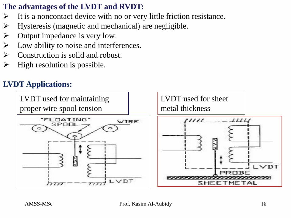
The advantages of the LVDT and RVDT:
It is a noncontact device with no or very little friction resistance.
Hysteresis (magnetic and mechanical) are negligible.
Output impedance is very low.
Low ability to noise and interferences.
Construction is solid and robust.
High resolution is possible.
LVDT Applications:
LVDT used for maintaining
proper wire spool tension
LVDT used for sheet
metal thickness

AMSS-MSc Prof. Kasim Al-Aubidy 19
4. Optical Sensors: Shaft Encoders:
Encoders are electro-mechanical devices that convert the angular position or
motion of a shaft or axle to an analog or digital code.
There are two main types: absolute and incremental (relative).
The output of absolute encoders indicates the current position of the shaft, making
them angle transducers.
It consists of a glass or plastic disc that rotates between a light source (LED) and a
pair of photo-detectors
Disk is encoded with alternate light and dark sectors so pulses are produced as disk
rotates.
When a disk with a pattern rotates, light
passing through the slits is transmitted or
blocked according to the pattern. The
received light is converted to electrical
currents in the detector elements, takes the
form of waves, and becomes digital
signals.

AMSS-MSc Prof. Kasim Al-Aubidy 20
Absolute Encoders:
Absolute encoders have a unique code that can be detected for every angular
position.
The optical absolute encoder's disc is made of glass or plastic with transparent and
opaque areas. A light source and photo detector array reads the optical pattern that
results from the disc's position at any one time.
They are available in the form of a “grey code”; a binary code of minimal change.
Absolute encoders are much more complex and expensive than incremental
encoders.
When to Use an Encoder:
Require accurate position
information:
10,000 line incremental
360 line absolute
Digital feed-back loop.
Compact and reasonably
rugged.

AMSS-MSc Prof. Kasim Al-Aubidy 21
Example:

AMSS-MSc Prof. Kasim Al-Aubidy 22
4. Hall Effect Sensors: There are two types of the Hall sensors:
Analog sensors: operates over a
broader voltage range and more
stable in a noisy environment.
These sensors are not quite linear
wrt the magnetic field density.
A bi-level sensor: in addition to
the amplifier contains a Schmitt
trigger with a built-in hysteresis of
the threshold level.
For position and displacement measurements, the Hall effect sensors must be
provided with a magnetic field source and interface electronic circuit. A magnetic
field has two important for this application characteristics: flux density and
polarity (or orientation).

AMSS-MSc Prof. Kasim Al-Aubidy 23
Example: liquid level detector
A permanent magnet is imbedded inside a float having a
hole in the center.
A bi-level Hall sensor is mounted at the top of the pole,
which should be fabricated on a nonmagnetic material.
When the liquid level rises and reaches the detection
level, the Hall switch triggers and sends signal to the
monitoring device.
When the liquid level drops below the release point plus
the threshold hysteresis, the Hall sensor output voltage
changes, indicating that the liquid level dropped.
The detection point depends on these key factors:
1. the magnet strength and shape,
2. the Hall sensor’s sensitivity,
3. the hysteresis, and
4. presence of ferromagnetic components in the
vicinity of the Hall sensor.

AMSS-MSc Prof. Kasim Al-Aubidy 24
Ultrasonic Detectors: These detectors are based on transmission to the object and receiving the reflected
acoustic waves.
For motion detection, they require a longer operating range and a wider angle of
coverage.
For noncontact distance measurements;
An ultrasonic sensor transmits a signal and receives a reflected signal from the
object.
When the waves are incident on an object, part of their energy is reflected.
Regardless of the direction where the energy comes from, it is reflected almost
uniformly within a wide solid angle, which may approach 180°.
If an object moves, the frequency of the reflected wavelength will differ from the
transmitted waves, this is called the Doppler effect.

AMSS-MSc Prof. Kasim Al-Aubidy 25
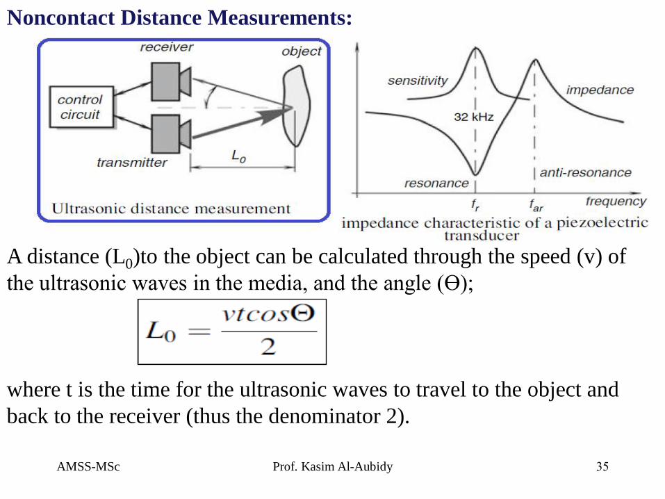
A distance (L0)to the object can be calculated through the speed (v) of
the ultrasonic waves in the media, and the angle (Ɵ);
where t is the time for the ultrasonic waves to travel to the object and
back to the receiver (thus the denominator 2).
Noncontact Distance Measurements:

AMSS-MSc Prof. Kasim Al-Aubidy 26
Noncontact Distance Measurements: If a transmitter and a receiver are positioned close to each other as compared with
the distance to the object, then CosƟ = 1.
Ultrasonic waves have an obvious advantage over the microwaves: they propagate
with the speed of sound (which is much slower than the speed of light at what the
microwaves propagate). Thus, time t is much longer and its measurement can be
accomplished easier and cheaper.
The input voltage applied to the ceramic
element causes it to flex and transmit
ultrasonic waves.
Because piezoelectricity is a reversible
phenomenon, the ceramic generates voltage
when incoming ultrasonic waves flex it. In
other words, the element may work as both
the sonic transmitter and receiver (a
microphone).
AMSS-MSc Prof. Kasim Al-Aubidy 27
Microwave Motion Detectors They offer an attractive alternative to cover large areas and to operate over an
extended temperature range under the influence of strong interferences.
These detectors are active sensors (provide an excitation signal). Thus they can
operate at day or night and do not rely on the external sources of energy.
Its operating principle is based on radiation of electromagnetic radiofrequency
(RF) waves toward a protected area. The electromagnetic waves reflected from
objects are received, amplified, and analyzed.
A time delay between the transmitted signal and received reflected signal is used to
measure distance to the object, while the frequency shift is used to measure speed
of motion of the object.

AMSS-MSc Prof. Kasim Al-Aubidy 28
Frequency Range of Microwave Signals:
The microwave detectors belong to the class of devices known as radars. Radar is
an acronym for RAdio Detection And Ranging.
The name microwave is assigned to the wavelengths (ʎ 4cm), i.e. 1GHz to 30
GHz. They are long enough to pass freely through most contaminants, such as
clouds and airborne dust, and short enough for being reflected by larger objects.

AMSS-MSc Prof. Kasim Al-Aubidy 29
Microwave Detector: It consists of; a Gunn oscillator, an Antenna, and a Mixer diode.
1. The Gunn Oscillator:
It is a diode mounted in a small precision cavity oscillates at microwave
frequencies.
It produces electromagnetic waves (frequency f0), part of which is directed through
an iris into a waveguide.
It is sensitive to the stability of applied dc voltage and, therefore, must be powered
by a good quality voltage regulator.
It may run continuously, or pulsed, which reduces the power consumption from the
power supply.
2. Focusing Antenna:
It directs the radiation toward the object.
Its focusing characteristics are determined by the application.
As a general rule, the narrower the directional diagram of the antenna, the
more sensitive it is (the antenna has a higher gain).
Another general rule is that a narrow-beam antenna is much larger, whereas a
wide-angle antenna can be quite small.

AMSS-MSc Prof. Kasim Al-Aubidy 30
The target reflects some waves back toward the antenna, which directs the
received radiation toward the mixing diode whose current contains a harmonic
with a phase differential between the transmitted and reflected waves.
The phase difference is in a direct relationship to the distance to the target. The
phase-sensitive detector is useful mostly for detecting the distance to an object.
3. Mixer diode:
In electronic a mixer is a nonlinear
circuit that creates new frequencies
from two signals applied to it.
A diode can be used to create a simple
mixer. This type of mixer produces
the original frequencies as well as
their sum and their difference.
Two signals (f1 &f2 ) are applied to a
mixer, and it produces new signals;
The sum (f1 + f2) and the difference (f1 - f2) of the original frequencies.
Note: There is no output unless both f1 and f2 inputs are present.

AMSS-MSc Prof. Kasim Al-Aubidy 31
The Doppler effect is the basis for the operation of microwave and ultrasonic
detectors. The Doppler effect device is responsive only to moving targets.
An antenna transmits the frequency (f0), which is defined as the ratio between the
speed of light in air (C0) and the wavelength (ʎ0);
When the target moves toward or away from the transmitting antenna, the
frequency of the reflected radiation will change. Thus, if the target is moving away
with velocity v, the reflected frequency will decrease and it will increase for the
approaching targets. This is called the Doppler effect.
Occupancy & Motion Detector:

AMSS-MSc Prof. Kasim Al-Aubidy 32
Doppler effect : It is the change in frequency of a wave for an observer moving relative to its source.
The frequency of reflected electromagnetic waves can be predicted by the Einstein’s
special theory of relativity as;
The above relation is true only for movements in the normal direction.
When the target moves at angles (Ɵ) with respect to the detector, then;
AMSS-MSc Prof. Kasim Al-Aubidy 33
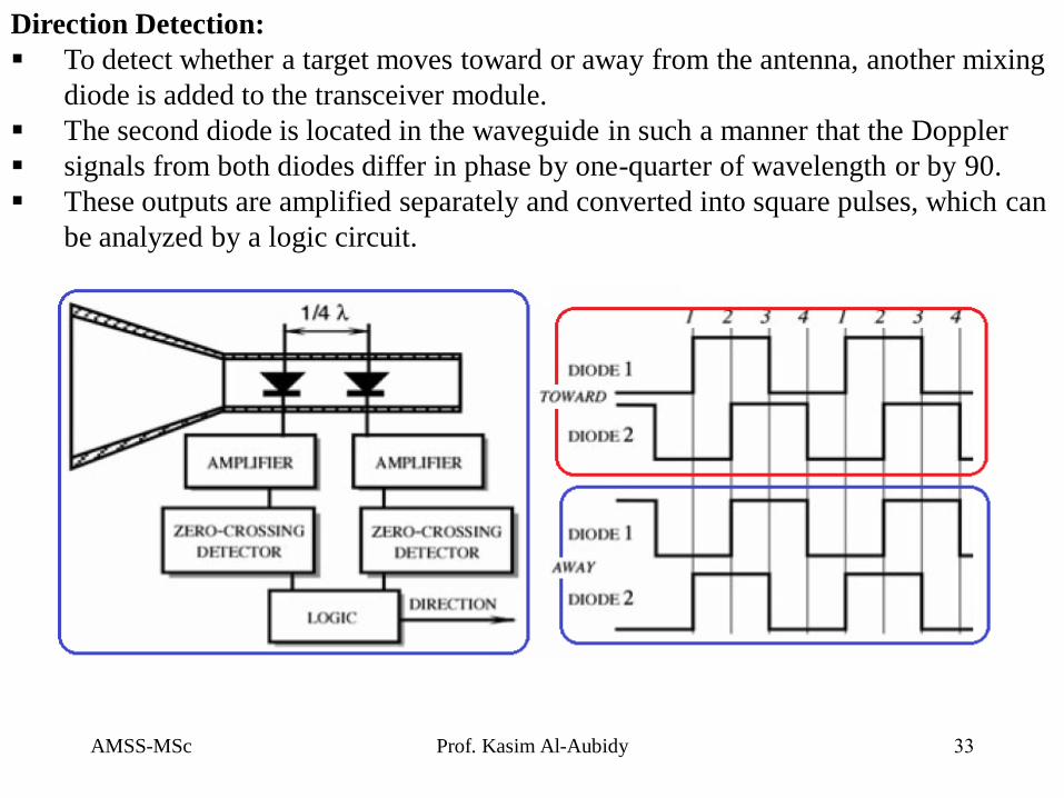
Direction Detection:
To detect whether a target moves toward or away from the antenna, another mixing
diode is added to the transceiver module.
The second diode is located in the waveguide in such a manner that the Doppler
signals from both diodes differ in phase by one-quarter of wavelength or by 90.
These outputs are amplified separately and converted into square pulses, which can
be analyzed by a logic circuit.

AMSS-MSc Prof. Kasim Al-Aubidy 34
6. Ultrasonic Sensors: These detectors are based on transmission
to the object and receiving the reflected
acoustic waves.
For motion detection, they require a
longer operating range and a wider angle
of coverage.
For noncontact distance measurements;
An ultrasonic sensor transmits a signal and receives a reflected signal from the
object.
When the waves are incident on an object, part of their energy is reflected.
Regardless of the direction where the energy comes from, it is reflected almost
uniformly within a wide solid angle, which may approach 180°.
If an object moves, the frequency of the reflected wavelength will differ from the
transmitted waves, this is called the Doppler effect.
AMSS-MSc Prof. Kasim Al-Aubidy 35
A distance (L0)to the object can be calculated through the speed (v) of
the ultrasonic waves in the media, and the angle (Ɵ);
where t is the time for the ultrasonic waves to travel to the object and
back to the receiver (thus the denominator 2).
Noncontact Distance Measurements:
AMSS-MSc Prof. Kasim Al-Aubidy 36
6. Microwave Sensors (Radar): The travel time of microwave signals is measured.
Due to the high value of light velocity, the duration of the pulses is only 1 ns,
otherwise the transmitted and received pulse would overlap.
Short pulses require special requirements on time interval measurement.
Micropower Impulse Radar (MIR):
MIR is a low-cost noncontact ranging sensor. Its operating principle is the same as of a
conventional pulse radar system.
MIR is used for sensing and measuring distances to objects in proximity to each other.
Commercial applications include:
Vehicles: parking assistance, backup warnings, pre-collision detection and smart
cruise control (measures the distance to the vehicles in front of you and if they get
too close, throttle is released and brakes are applied).
Appliances: stud finders and laser tape measures.
Security: home intrusion motion sensors and perimeter surveillance.
Search and rescue: MIR can detect the beating of a human heart or respiration
from long distances.

AMSS-MSc Prof. Kasim Al-Aubidy 37
MIR Architecture:
It consists of a white noise generator whose output signal triggers a pulse generator.
The pulse generator produces very short pulses with the average rate of 2
MHz±20%. Each pulse has a fixed short duration (), while the repetition of these
pulses is random, according to triggering by the noise generator.
The distance between the pulses ranges from 200 to 625 ns. It can be said that the
pulses have a pulse-position modulation (PPM) by white noise with the maximum
index of 20%.

AMSS-MSc Prof. Kasim Al-Aubidy 38
The square wave pulses cause the AM
of a radio transmitter.
The modulation has a 100% depth, that
is, the transmitter is turned on and off
by the pulses. Such a double-step
modulation is called PPM-AM.
The radiotransmitter produces short bursts of high-frequency radio packest, which
propagate from the transmitting antenna to the surrounding space.
The electromagnetic waves reflect from the objects and propagate back to the radar.
The same pulse generator, which modulates the transmitter, with a predetermined
delay gates the radio receiver to enable reception by the MIR only during a specific
time window when the reflected waves are expected to arrive.
The reflected pulses are received, demodulated, and the time delay with respect to
the transmitted pulses is measured.
The time delay is proportional to distance D from the antenna to the object from
which the radio waves are reflected: td= 2D/c, where c is the speed of light.

AMSS-MSc Prof. Kasim Al-Aubidy 39
Capacitive Occupancy Detectors: A human body develops a coupling capacitance to its surroundings. Its value (from
few pF to several nF) depends on; body size, clothing, materials, weather, type of
surrounding objects, and so forth.
When a person moves, the coupling capacitance changes, thus making it possible to
discriminate static objects from moving objects.
The resulting capacitance (C) between the test plate and the earth becomes;

AMSS-MSc Prof. Kasim Al-Aubidy 40
Example: Capacitive security system for an automobile
A sensing probe is imbedded into a car
seat to form one plate of a capacitor (Cp).
The other plate of the capacitor is formed
either by a body of an automobile, or by
a separate plate positioned under a floor
mat. A reference capacitor (Cx) is placed
close to the seat probe.
Both RC circuits have nearly equal time
constants (1).
When a person is positioned on the seat,
her body forms an additional capacitance
in parallel with Cp, thus increasing a
time constant of the R1Cp-network from
(1) to (2).

AMSS-MSc Prof. Kasim Al-Aubidy 41
Example: Capacitive proximity sensor
Any object approaching the robot arm (an electrode) forms a capacitive coupling
(Cso) with it. A coupling capacitance is used to detect the proximity.
Without the shield, the electric field is
distributed between the electrode and the
robot, while a driven shield directs electric
field toward the object.
Oscillator frequency depends on the net
input capacitance (Csg , Cso, and Cog).
This circuit allows to detect proximity to
conductive objects over the range of 30 cm.

AMSS-MSc Prof. Kasim Al-Aubidy 42
References:
1. Shetty and Kolk , “Mechatronics System Design”, 2nd edition, Cenage Learning, 2011.
2. Kilian. Delmer, “Modern Control Technology: Components and Systems”, 2nd edition Publication,2013.
3. Jacob Fraden, “Handbook of Modern Sensors; Physics, Design, and Applications”, Fourth Edition,
Springer Press 2010.
4. Kelley CT (2003) Solving nonlinear equations with Newton’s method, No. 1 Fundamentals of
Algorithms. SIAM, Philadelphia, PA
5. ISO guide to the expression of uncertainty in measurements (1993) International Organization for
Standardization, Geneva, Switzerland
6. Taylor BN, Kuyatt CE (1994) Guidelines for evaluation and expressing the uncertainty of NIST
measurement results. NIST Technical Note 1297. US Government Printing Office, Washington DC
7. Widlar RJ (1980) Working with high impedance Op Amps, AN24, Linear Application Handbook.
National Semiconductor
8. Sheingold DH (ed) (1986) Analog-Digital Conversion Handbook. 3rd ed., Prentice-Hall, Englewood
Cliffs, NJ.
9. Williams J (1990) Some techniques for direct digitization of transducer outputs, AN7, Linear Technology
Application Handbook.
10. Long DJ (1975) Occupancy detector apparatus for automotive safety system. US Patent 3,898,472, 5 Aug
11. Park YE, Wise KD (1983) An MOS switched-capacitor readout amplifier for capacitive pressure sensors.
IEEE Custom IC Conf 380–384.
12. Ryser P, Pfister G (1991) Optical fire and security technology: sensor principles and detection
intelligence. In: Transducers’91. International conference on solid-state sensors and actuators. Digest of
technical papers, pp 579–583, IEEE