Embed Size (px)
Citation preview
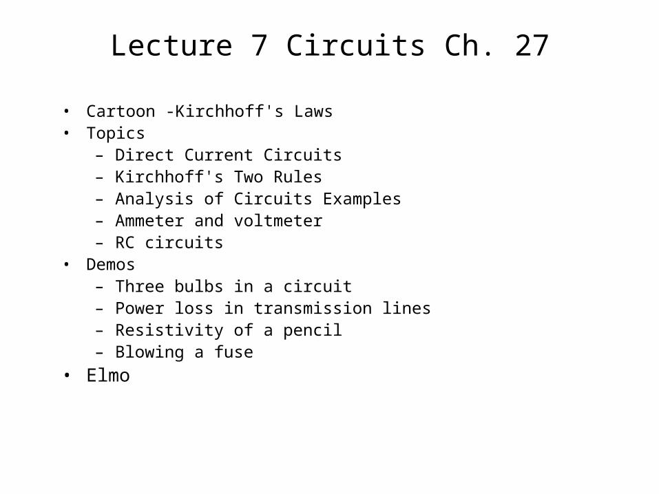
Lecture 7 Circuits Ch. 27
• Cartoon -Kirchhoff's Laws• Topics
– Direct Current Circuits– Kirchhoff's Two Rules– Analysis of Circuits Examples– Ammeter and voltmeter– RC circuits
• Demos– Three bulbs in a circuit– Power loss in transmission lines– Resistivity of a pencil– Blowing a fuse
• Elmo
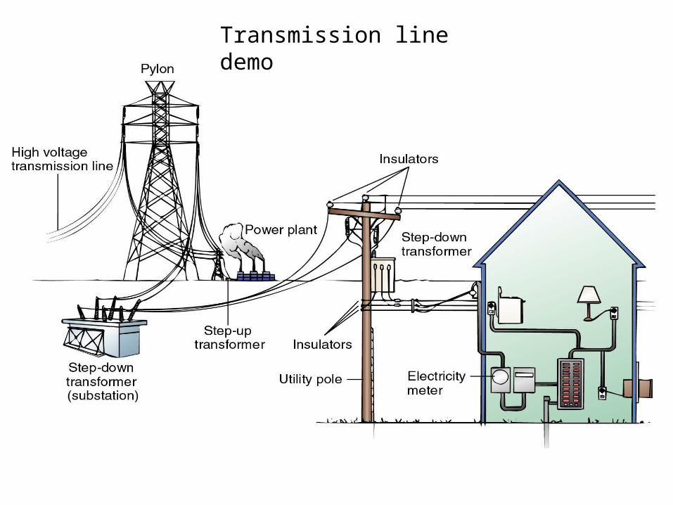
Transmission line demo
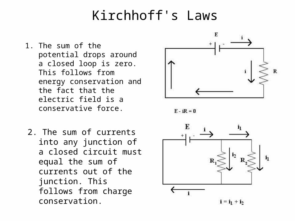
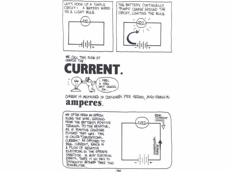
Kirchhoff's Laws
1. The sum of the potential drops around a closed loop is zero. This follows from energy conservation and the fact that the electric field is a conservative force.
2. The sum of currents into any junction of a closed circuit must equal the sum of currents out of the junction. This follows from charge conservation.
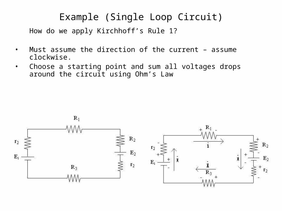
Example (Single Loop Circuit)
How do we apply Kirchhoff’s Rule 1?
• Must assume the direction of the current – assume clockwise.• Choose a starting point and sum all voltages drops around the circuit using
Ohm’s Law
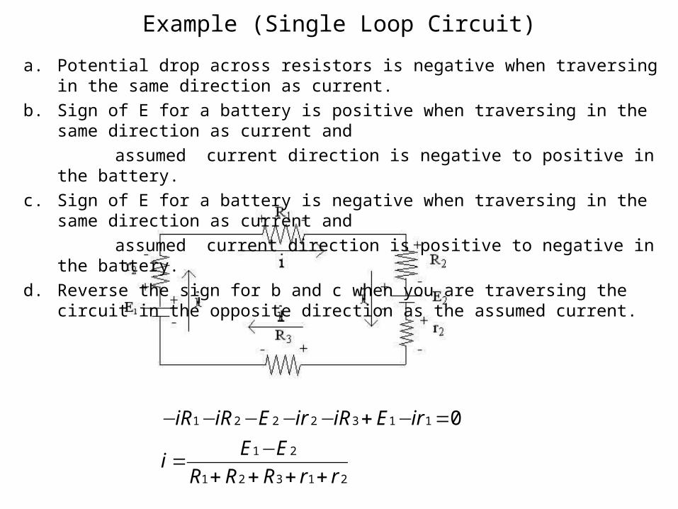
Example (Single Loop Circuit)
21321
21
1132221 0
rrRRR
EEi
irEiRirEiRiR
++++−
=
=−+−−−−−
a. Potential drop across resistors is negative when traversing in the same direction as current.
b. Sign of E for a battery is positive when traversing in the same direction as current and
assumed current direction is negative to positive in the battery.
c. Sign of E for a battery is negative when traversing in the same direction as current and
assumed current direction is positive to negative in the battery.
d. Reverse the sign for b and c when you are traversing the circuit in the opposite direction as the assumed current.
21321
21
rrRRR
EEi
++++−
=
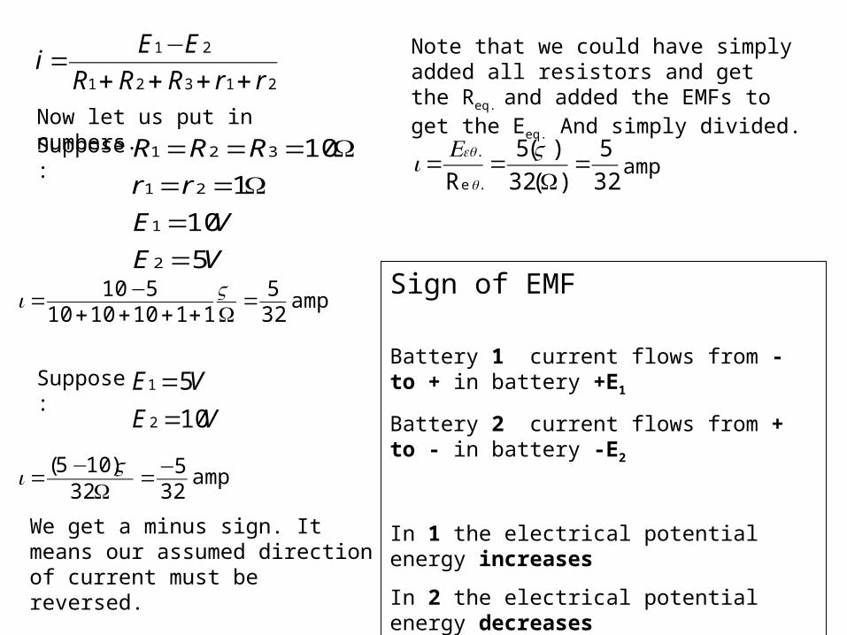
Now let us put in numbers.
VE
VE
rr
RRR
5
10
1
10
2
1
21
321
==
Ω==Ω===Suppose:
325
11101010510 =
Ω++++−= Vi amp
VE
VE
10
5
2
1
==Suppose:
325
32)105( −=
Ω−= Vi amp
We get a minus sign. It means our assumed direction of current must be reversed.
Note that we could have simply added all resistors and get the Req. and added the EMFs to get the Eeq. And simply divided.
32
5
)(32
)(5
R .e
.=
Ω==
VEi
q
eqamp
Sign of EMF
Battery 1 current flows from - to + in battery +E1
Battery 2 current flows from + to - in battery -E2
In 1 the electrical potential energy increases
In 2 the electrical potential energy decreases
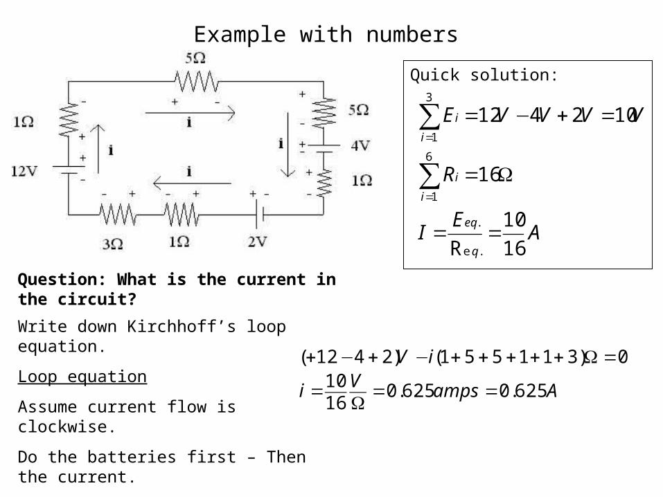
Example with numbers
Quick solution:
AE
I
R
VVVVE
q
eq
i
i
i
i
16
10
R
16
102412
.e
.
6
1
3
1
==
Ω=
=+−=
∑
∑
=
=
Question: What is the current in the circuit?
AampsVi
iV
625.0625.01610
0)311551()2412(
==Ω
=
=Ω+++++−+−+
Write down Kirchhoff’s loop equation.
Loop equation
Assume current flow is clockwise.
Do the batteries first – Then the current.
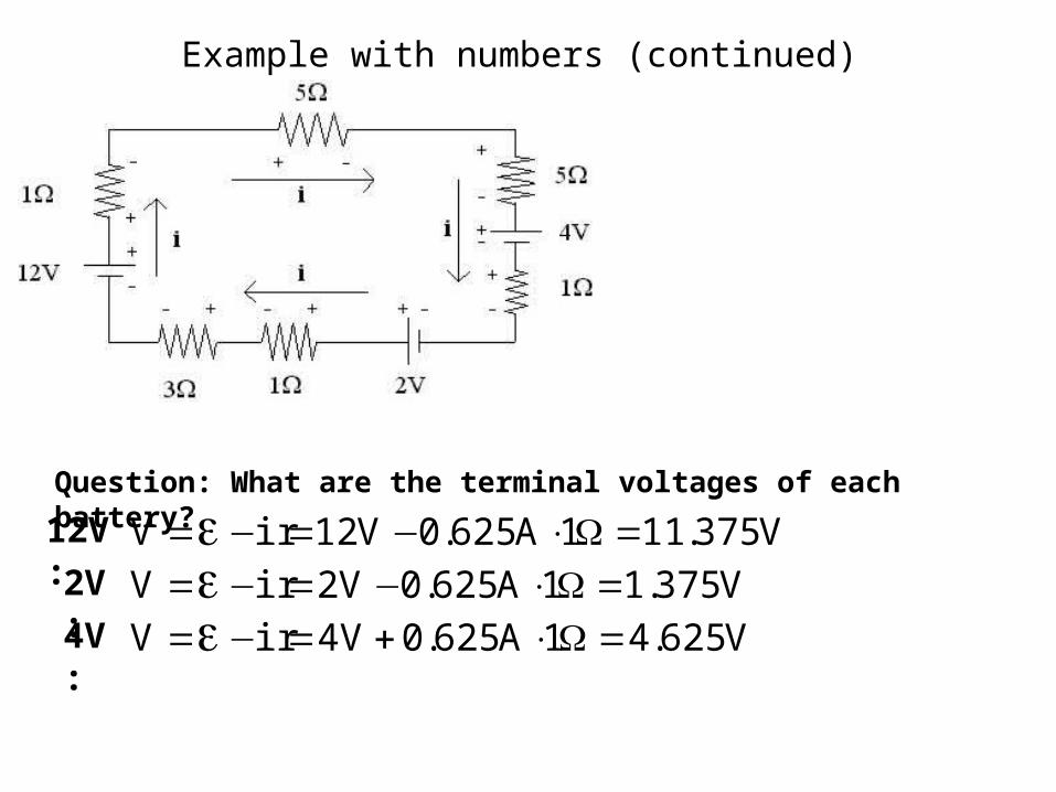
Example with numbers (continued)
Question: What are the terminal voltages of each battery?
V375.111A625.0V12irV =Ω⋅−=−=εV375.11A625.0V2irV =Ω⋅−=−=εV625.41A625.0V4irV =Ω⋅+=−=ε
2V:
4V:
12V:
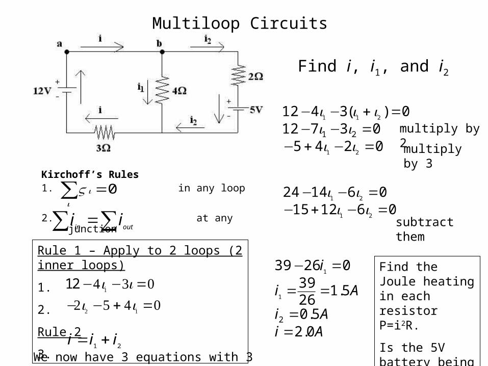
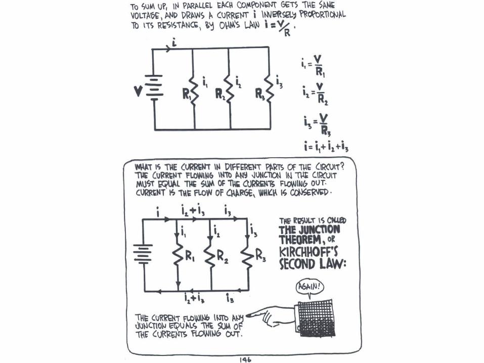
Multiloop Circuits
Kirchoff’s Rules1. in any loop
2. at any junction
0=∑i
iV
∑∑ =outinii
Find i, i1, and i2
Rule 1 – Apply to 2 loops (2 inner loops)
1.
2.
Rule 2
3.
12 −4i1 −3i =0−2i2 −5 + 4i1 =0
21iii +=
We now have 3 equations with 3 unknowns.
024503712
0)(3412
21
211
21
=−+−=−−
=+−−
iiii
iii
061215061424
21
21
=−+−=−−ii
ii
AiAi
Ai
i
0.25.0
5.12639
02639
2
1
1
==
==
=−
multiply by 2
multiply by 3
subtract them
Find the Joule heating in each resistor P=i2R.
Is the 5V battery being charged?
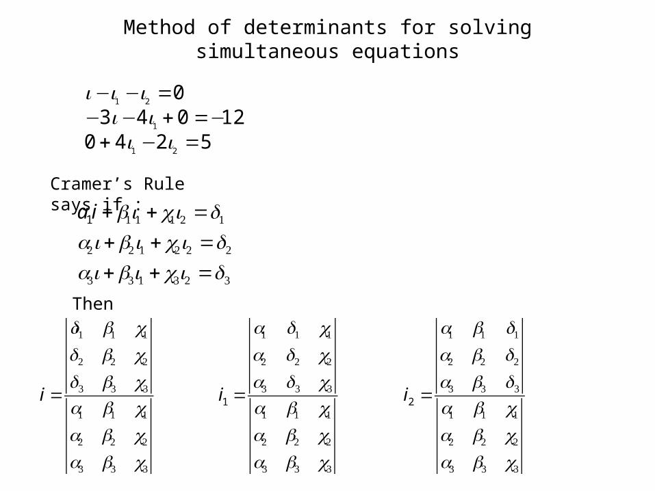
Method of determinants for solving simultaneous equations
524012043
0
21
1
21
=−+−=+−−
=−−
iiiiiii
Cramer’s Rule says if :
a1i +b1i1 + c1i2 =d1
a2i +b2i1 + c2i2 =d2
a3i +b3i1 + c3i2 =d3
Then,
i =
d1 b1 c1d2 b2 c2
d3 b3 c3
a1 b1 c1a2 b2 c2
a3 b3 c3
i1 =
a1 d1 c1a2 d2 c2
a3 d3 c3
a1 b1 c1a2 b2 c2
a3 b3 c3
i2 =
a1 b1 d1
a2 b2 d2
a3 b3 d3
a1 b1 c1a2 b2 c2
a3 b3 c3
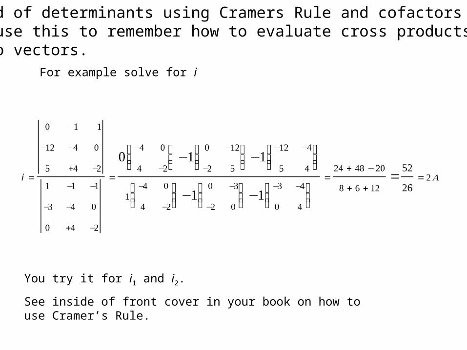
i =
0 −1 −1
−12 −4 0
5 +4 −2
1 −1 −1
−3 −4 0
0 +4 −2
=
0−4 0
4 −2
⎛⎝⎜
⎞⎠⎟−1
0 −12
−2 5
⎛⎝⎜
⎞⎠⎟−1
−12 −4
5 4
⎛⎝⎜
⎞⎠⎟
1−4 0
4 −2
⎛⎝⎜
⎞⎠⎟−1
0 −3
−2 0
⎛⎝⎜
⎞⎠⎟−1
−3 −4
0 4
⎛⎝⎜
⎞⎠⎟
=24 + 48 −20
8 + 6 + 12=
52
26=2A
You try it for i1 and i2.
See inside of front cover in your book on how to use Cramer’s Rule.
For example solve for i
Method of determinants using Cramers Rule and cofactorsAlso use this to remember how to evaluate cross products of two vectors.
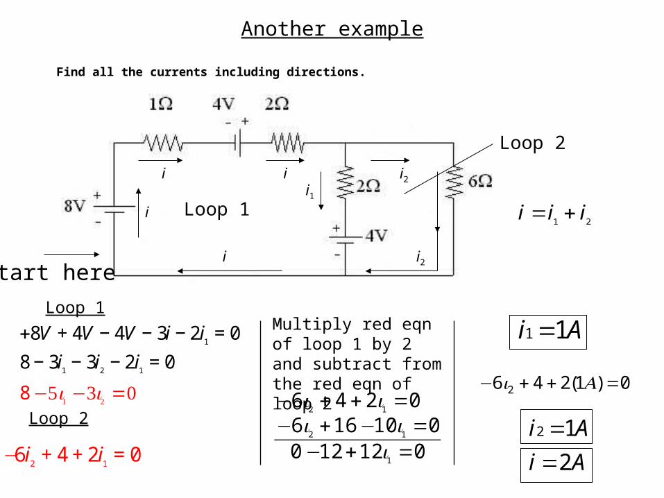
Another example
Find all the currents including directions.
+8V + 4V − 4V − 3i − 2i1
= 0
8 − 3i1− 3i
2− 2i
1= 0
012120010166
0246
1
12
12
=+−=−+−
=++−
iii
ii0)1(246 2 =++− Ai
Loop 1
Loop 2
Ai 11 =
Ai
Ai
2
12
==
Loop 1
Loop 2
i i
i
i
i1i2
i2
21iii +=
−6i2
+ 4 + 2i1
= 0
Multiply red eqn of loop 1 by 2 and subtract from the red eqn of loop 2
Start here
8 −5i1 −3i2 =0
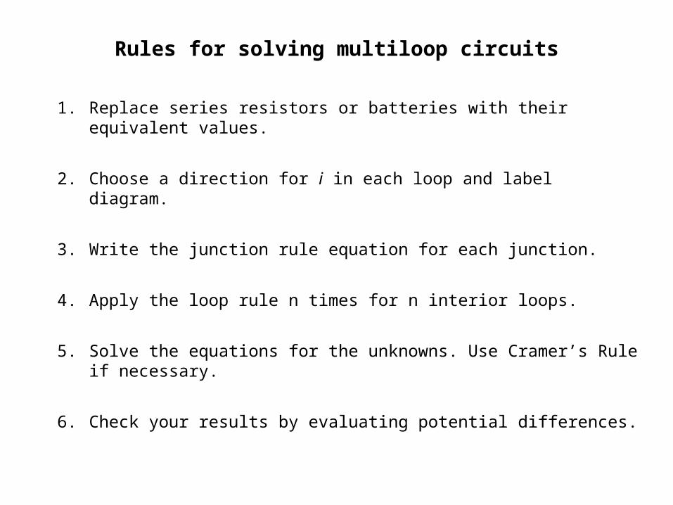
Rules for solving multiloop circuits
1. Replace series resistors or batteries with their equivalent values.
2. Choose a direction for i in each loop and label diagram.
3. Write the junction rule equation for each junction.
4. Apply the loop rule n times for n interior loops.
5. Solve the equations for the unknowns. Use Cramer’s Rule if necessary.
6. Check your results by evaluating potential differences.
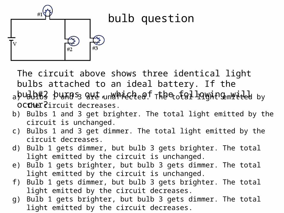
3 bulb question
The circuit above shows three identical light bulbs attached to an ideal battery. If the bulb#2 burns out, which of the following will occur?
a) Bulbs 1 and 3 are unaffected. The total light emitted by the circuit decreases.b) Bulbs 1 and 3 get brighter. The total light emitted by the circuit is unchanged.c) Bulbs 1 and 3 get dimmer. The total light emitted by the circuit decreases.d) Bulb 1 gets dimmer, but bulb 3 gets brighter. The total light emitted by the circuit is
unchanged.e) Bulb 1 gets brighter, but bulb 3 gets dimmer. The total light emitted by the circuit is
unchanged.f) Bulb 1 gets dimmer, but bulb 3 gets brighter. The total light emitted by the circuit
decreases.g) Bulb 1 gets brighter, but bulb 3 gets dimmer. The total light emitted by the circuit
decreases.h) Bulb 1 is unaffected, but bulb 3 gets brighter. The total light emitted by the circuit
increases.i) None of the above.
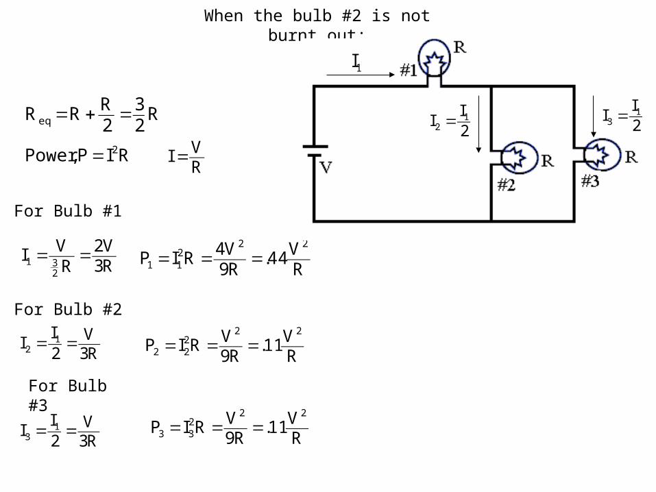
When the bulb #2 is not burnt out:
R23
2RRR eq =+=
R3V2
RVI
231 ==
RIP,Power 2=RVI =
For Bulb #1
For Bulb #2
For Bulb #3
RV44.
R9V4RIP
22211 ===
R3V
2I
I 12 ==
RV11.
R9VRIP
22222 ===
R3V
2I
I 13 == R
V11.R9
VRIP22
233 ===
1I
2I
I 12 = 2
II 1
3 =
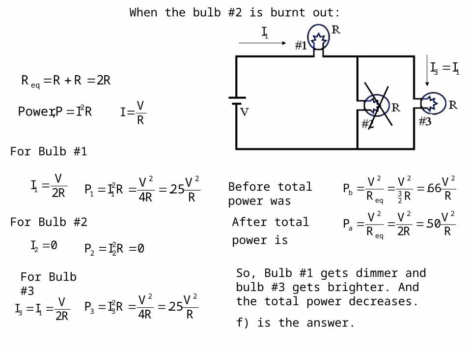
R2RRR eq =+=
R2VI1 =
RIP,Power 2=RVI =
For Bulb #1
For Bulb #2
For Bulb #3
RV25.
R4VRIP
22211 ===
0I2 = 0RIP 222 ==
R2VII 13 == R
V25.R4
VRIP22
233 ===
1I
13 II =
So, Bulb #1 gets dimmer and bulb #3 gets brighter. And the total power decreases.
f) is the answer.
Before total power wasRV66.
RV
RVP
2
23
2
eq
2
b ===
RV50.
R2V
RVP
22
eq
2
a ===After total power is
When the bulb #2 is burnt out:
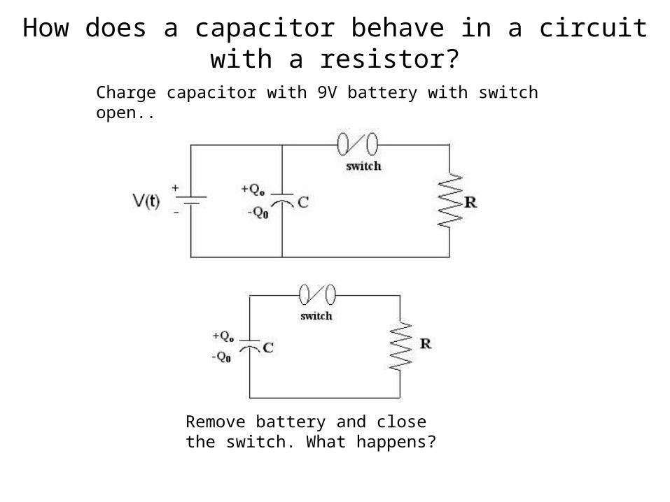
How does a capacitor behave in a circuit with a resistor?
Charge capacitor with 9V battery with switch open..
Remove battery and close the switch. What happens?
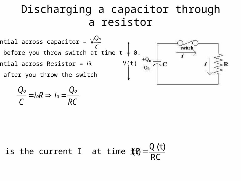
Discharging a capacitor through a resistor
V(t)
Potential across capacitor = V =
just before you throw switch at time t = 0.
Potential across Resistor = iR
Just after you throw the switch
RC
QiRi
C
Q ooo
o=⇒=
C
Qo
What is the current I at time t?RC
)t(Q)t(i =
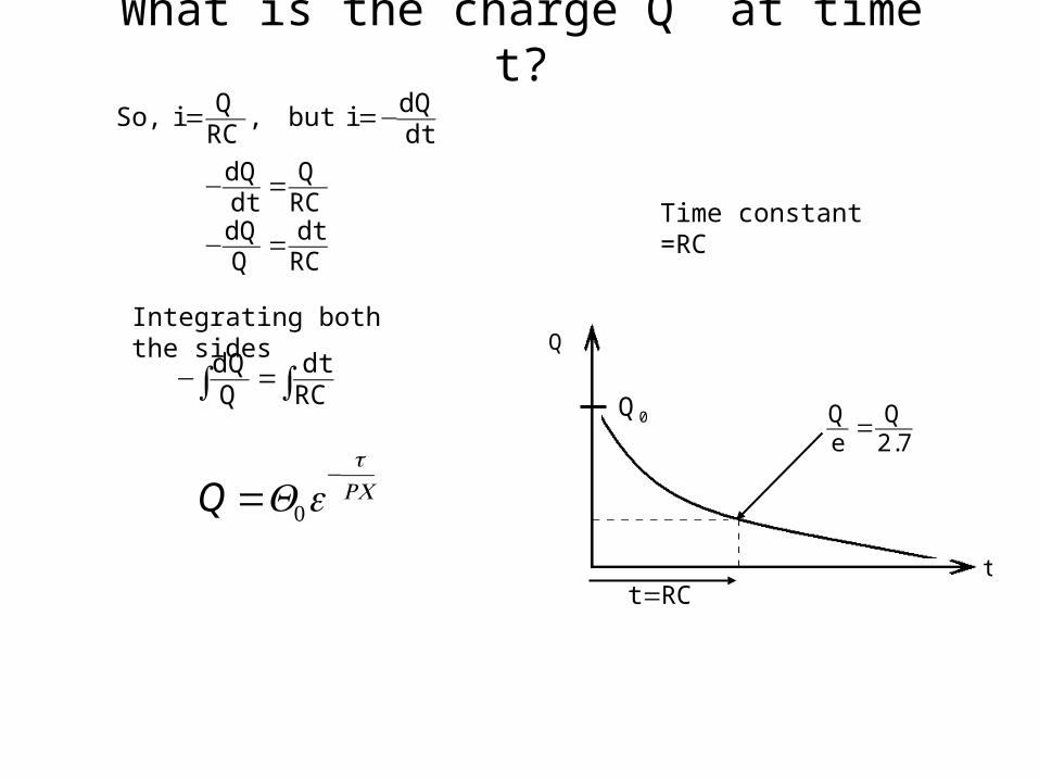
dtdQi but ,
RCQi ,So −==
RCdt
QdQ
RCQ
dtdQ
=−
=−
Integrating both the sides
∫ ∫=−RCdt
QdQ
Q =Q0e−
tRC
Time constant =RC
Q
0Q
RCt =
7.2Q
eQ =
t
What is the charge Q at time t?
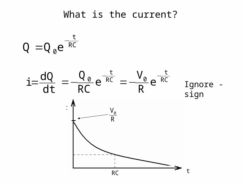
RCt
0eQQ−
=
dtdQi = Ignore - sign
i
tRC
RV0
What is the current?
RCt
0RCt
0 eRV
eRCQ −−
−=−=
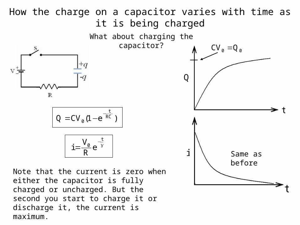
How the charge on a capacitor varies with time as it is being charged
What about charging the capacitor?
t
Q
i
t
00 QCV =
Same as before
)e1(CVQ RCt
0
−−=
γ−
=t
0 eRV
i
Note that the current is zero when either the capacitor is fully charged or uncharged. But the second you start to charge it or discharge it, the current is maximum.
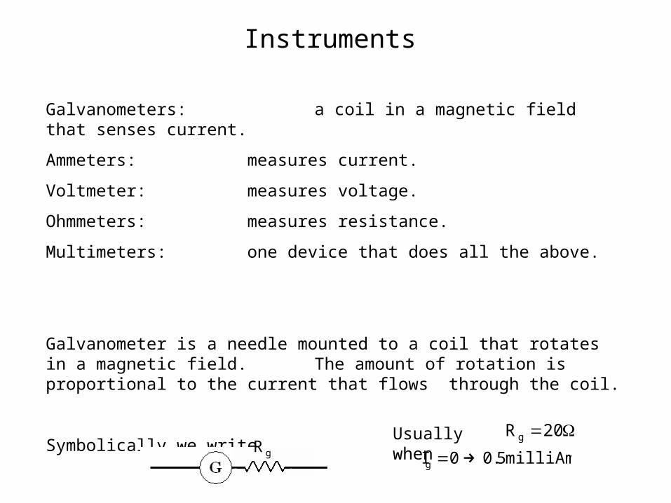
Instruments
Galvanometers: a coil in a magnetic field that senses current.
Ammeters: measures current.
Voltmeter: measures voltage.
Ohmmeters: measures resistance.
Multimeters: one device that does all the above.
Galvanometer is a needle mounted to a coil that rotates in a magnetic field. The amount of rotation is proportional to the current that flows
through the coil.
Symbolically we write
gRUsually when Ω=20Rg
milliAmp5.00Ig →=
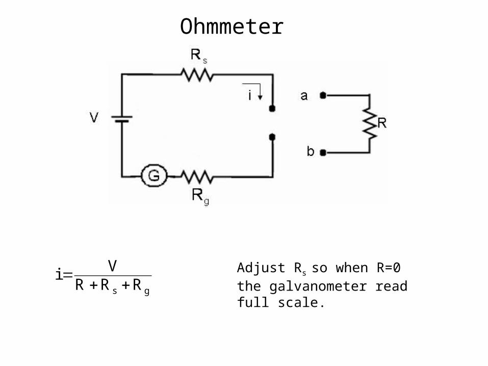
Ohmmeter
gs RRRVi
++= Adjust Rs so when R=0 the
galvanometer read full scale.
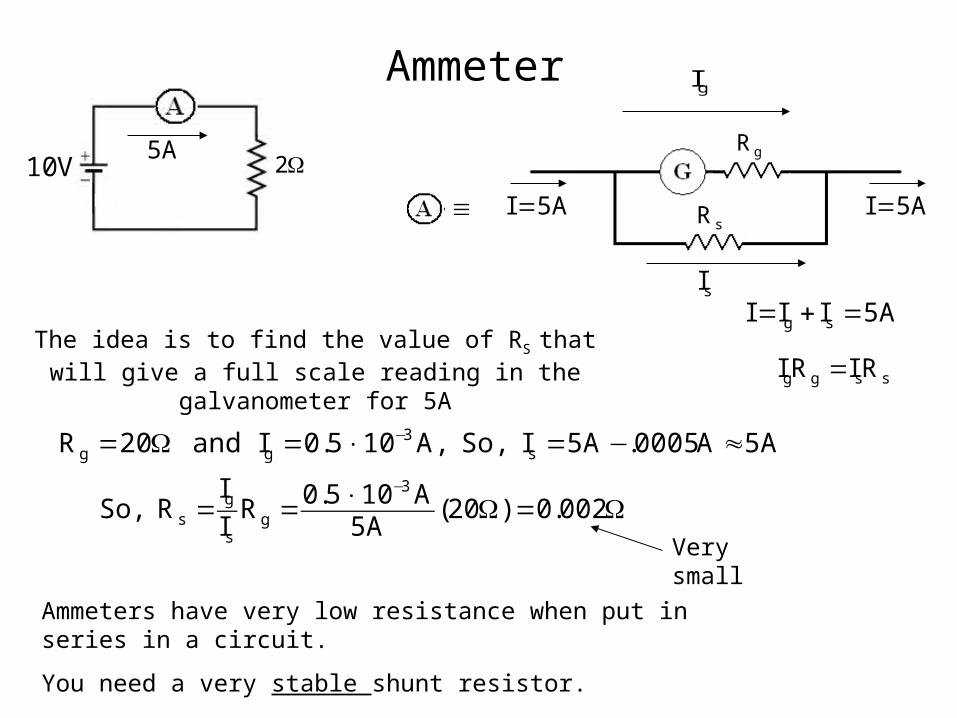
Ammeter
V10A5 Ω2
gI
gR
sR
sI
A5I = A5I =≡
A5III sg =+=
ssgg RIRI =The idea is to find the value of RS that will give a full
scale reading in the galvanometer for 5A
A5A0005.A5I So, ,A105.0I and 20R s3
gg ≈−=×=Ω= −
Ω=Ω×==−
002.0)20(A5
A105.0RI
IR ,So
3
gs
gs
Ammeters have very low resistance when put in series in a circuit.
You need a very stable shunt resistor.
Very small
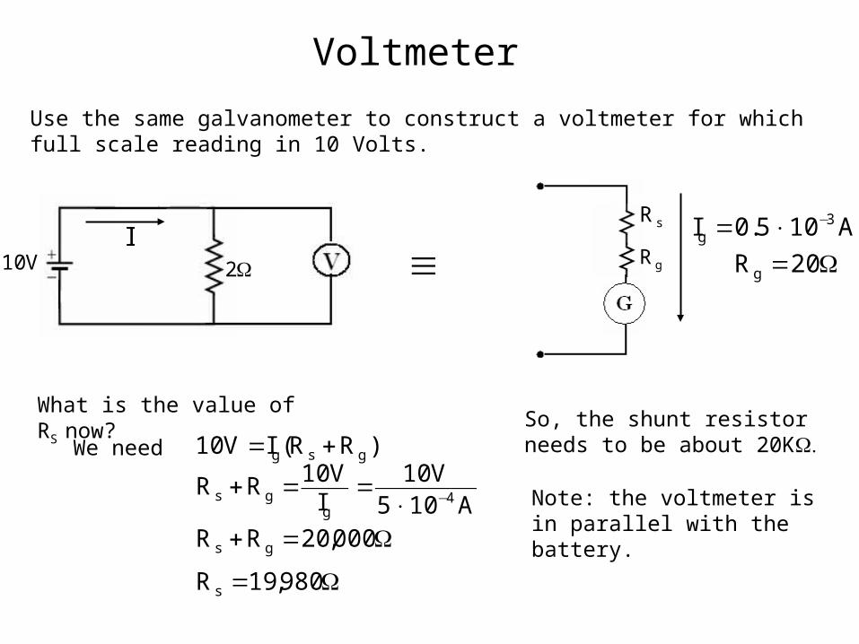
Voltmeter
Use the same galvanometer to construct a voltmeter for which full scale reading in 10 Volts.
≡V10 Ω2
sR
gRI
Ω=×= −
20R
A105.0I
g
3g
What is the value of RS now?
)RR(IV10 gsg +=
A105V10
IV10RR
4g
gs −×==+
Ω=+ 000,20RR gs
Ω= 980,19Rs
So, the shunt resistor needs to be about 20K
Note: the voltmeter is in parallel with the battery.
We need
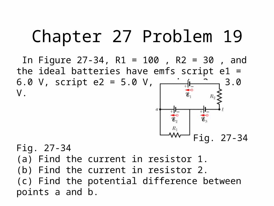
Chapter 27 Problem 19 In Figure 27-34, R1 = 100 , R2 = 30 , and the ideal batteries have emfs script e1 = 6.0 V, script e2 = 5.0 V, script e3 = 3.0 V.
Fig. 27-34(a) Find the current in resistor 1.(b) Find the current in resistor 2.(c) Find the potential difference between points a and b.
Fig. 27-34
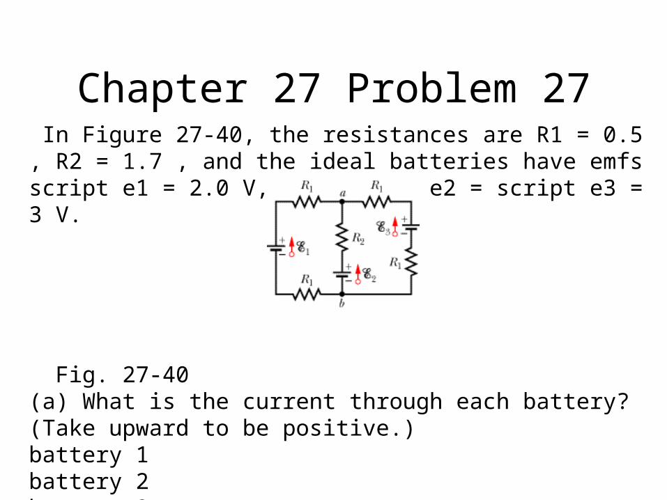
Chapter 27 Problem 27 In Figure 27-40, the resistances are R1 = 0.5 , R2 = 1.7 , and the ideal batteries have emfs script e1 = 2.0 V, and script e2 = script e3 = 3 V.
Fig. 27-40(a) What is the current through each battery? (Take upward to be positive.)battery 1battery 2battery 3(b) What is the potential difference Va - Vb?
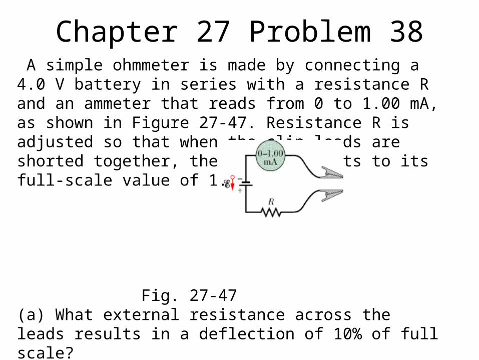
Chapter 27 Problem 38 A simple ohmmeter is made by connecting a 4.0 V battery in series with a resistance R and an ammeter that reads from 0 to 1.00 mA, as shown in Figure 27-47. Resistance R is adjusted so that when the clip leads are shorted together, the meter deflects to its full-scale value of 1.00 mA.
Fig. 27-47(a) What external resistance across the leads results in a deflection of 10% of full scale?(b) What resistance results in a deflection of 50% of full scale?(c) What resistance results in a deflection of 90% of full scale?(d) If the ammeter has a resistance of 40.0 and the internal resistance of the battery is negligible, what is the value of R?