Embed Size (px)
Citation preview
Machine Design II Prof. K.Gopinath & Prof. M.M.Mayuram
Indian Institute of Technology Madras
Module 2 - GEARS
Lecture 6 – GEAR FAILURE
Contents
6.1. Introduction
Modes of Gear Failure
6.2 Scoring
6.2.1. Initial Scoring
6.2.2. Moderate Scoring
6.2.3. Destructive Scoring
6.2.4. Frosting
6.3 Wear
6.3.1. Adhesive
6.3.2. Abrasive
6.3.3. Corrosive
6.4. Pitting
6.4.1. Subsurface origin failure
6.4. 2. Surface origin failure
6.5. Plastic Flow
6.5. 1. Cold flow
6.5. 2. Ridging
6.5. 3. Rippling
6.6. Tooth Breakage
6.6. 1. Fatigue breakage
6.6. 2. Overload breakage
6.7. Gear noise
Machine Design II Prof. K.Gopinath & Prof. M.M.Mayuram
Indian Institute of Technology Madras
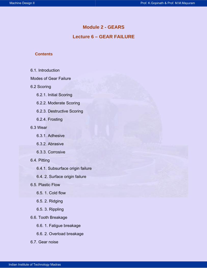
6.1 INTRODUCTION
Gear failure can occur in various modes. In this chapter details of failure are
given. If care is taken during the design stage itself to prevent each of these
failure a sound gear design can be evolved. The gear failure is explained by
means of flow diagram in Fig.. 1.
Fig. 6.1 Different modes of failure
6.1 SCORING:
Scoring is due to combination of two distinct activities: First, lubrication failure in
the contact region and second, establishment of metal to metal contact. Later
on, welding and tearing action resulting from metallic contact removes the metal
rapidly and continuously so far the load, speed and oil temperature remain at the
same level. The scoring is classified into initial, moderate and destructive.
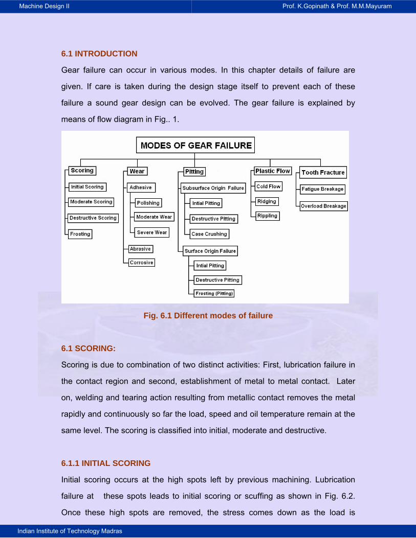
6.1.1 INITIAL SCORING
Initial scoring occurs at the high spots left by previous machining. Lubrication
failure at these spots leads to initial scoring or scuffing as shown in Fig. 6.2.
Once these high spots are removed, the stress comes down as the load is
Machine Design II Prof. K.Gopinath & Prof. M.M.Mayuram
Indian Institute of Technology Madras
distributed over a larger area. The scoring will then stop if the load, speed and
temperature of oil remain unchanged or reduced. Initial scoring is non-
progressive and has corrective action associated with it.
Fig. 6.2 Initial scoring
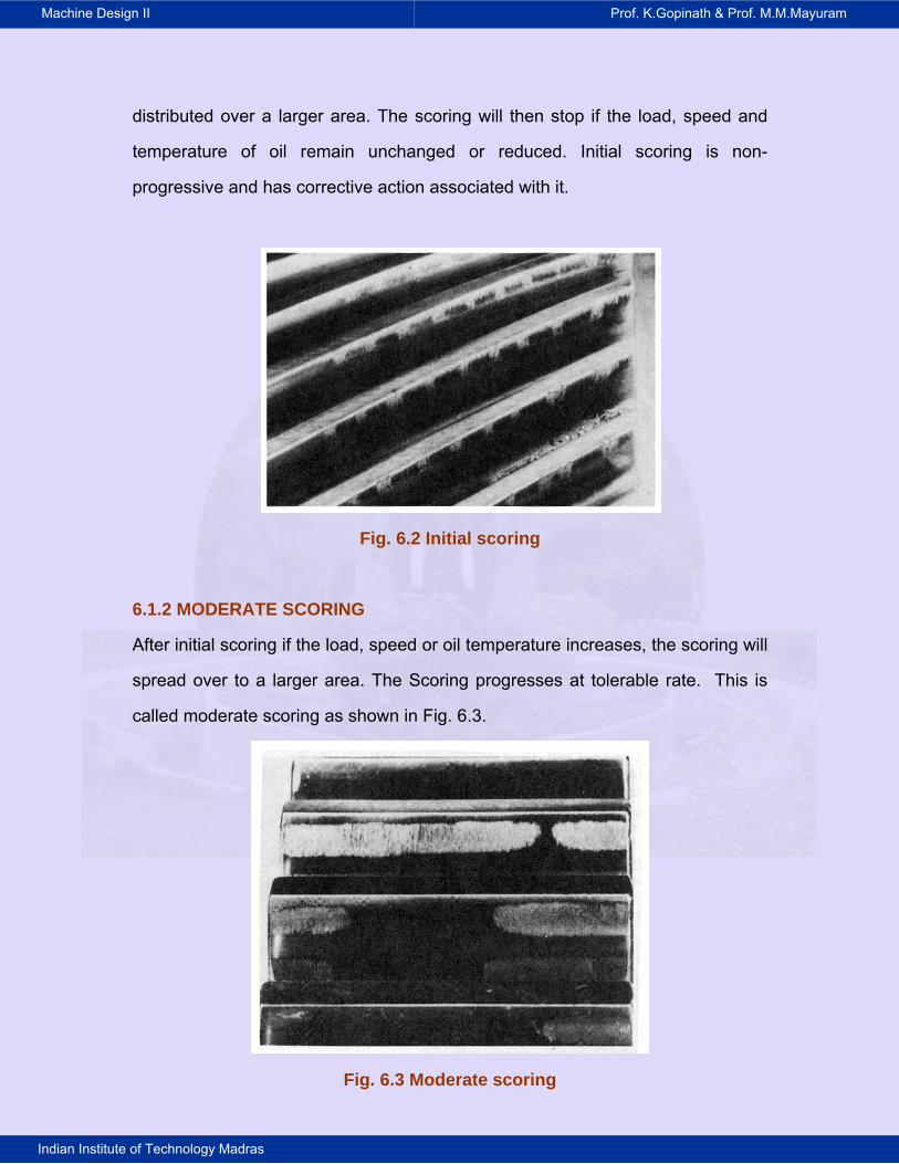
6.1.2 MODERATE SCORING
After initial scoring if the load, speed or oil temperature increases, the scoring will
spread over to a larger area. The Scoring progresses at tolerable rate. This is
called moderate scoring as shown in Fig. 6.3.
Fig. 6.3 Moderate scoring
Machine Design II Prof. K.Gopinath & Prof. M.M.Mayuram
Indian Institute of Technology Madras
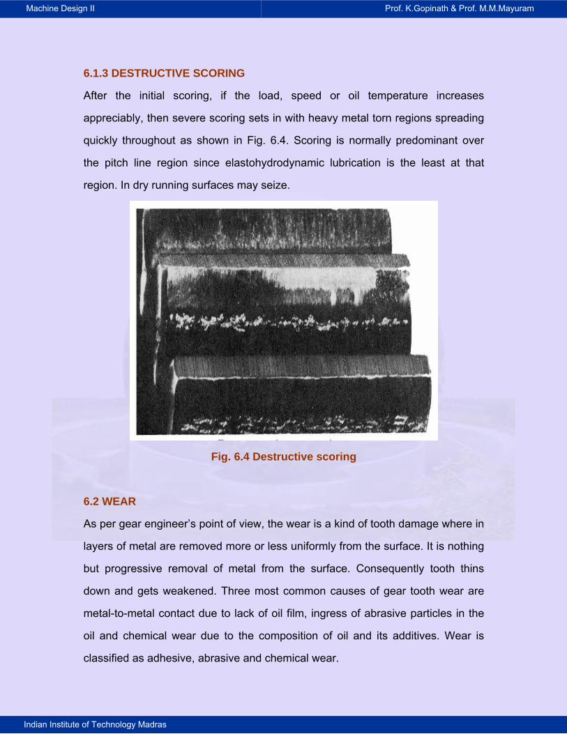
6.1.3 DESTRUCTIVE SCORING
After the initial scoring, if the load, speed or oil temperature increases
appreciably, then severe scoring sets in with heavy metal torn regions spreading
quickly throughout as shown in Fig. 6.4. Scoring is normally predominant over
the pitch line region since elastohydrodynamic lubrication is the least at that
Fig. 6.4 Destructive scoring
il and its additives. Wear is
lassified as adhesive, abrasive and chemical wear.
region. In dry running surfaces may seize.
6.2 WEAR
As per gear engineer’s point of view, the wear is a kind of tooth damage where in
layers of metal are removed more or less uniformly from the surface. It is nothing
but progressive removal of metal from the surface. Consequently tooth thins
down and gets weakened. Three most common causes of gear tooth wear are
metal-to-metal contact due to lack of oil film, ingress of abrasive particles in the
oil and chemical wear due to the composition of o
c
Machine Design II Prof. K.Gopinath & Prof. M.M.Mayuram
Indian Institute of Technology Madras
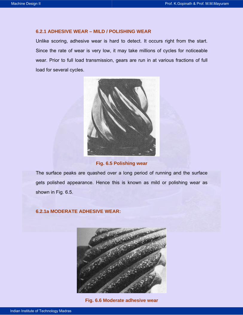
6.2.1 ADHESIVE WEAR – MILD / POLISHING WEAR
Unlike scoring, adhesive wear is hard to detect. It occurs right from the start.
Since the rate of wear is very low, it may take millions of cycles for noticeable
wear. Prior to full load transmission, gears are run in at various fractions of full
load for several cycles.
arance. Hence this is known as mild or polishing wear as
hown in Fig. 6.5.
6.2.1a MODERATE ADHESIVE WEAR:
Fig. 6.6 Moderate adhesive wear
Fig. 6.5 Polishing wear
The surface peaks are quashed over a long period of running and the surface
gets polished appe
s
Machine Design II Prof. K.Gopinath & Prof. M.M.Mayuram
Indian Institute of Technology Madras
When the load and speed of operation are more than mild wear conditions,
moderate wear takes place with higher rate. Worn out portions appear bright and
shiny. Yet it occurs over a long period. A typical example of this wear in helical
gear is shown in the Fig. 6.6.
6.2.2 ABRASIVE WEAR
Abrasive wear is the principal reason for the failure of open gearing and closed
gearing of machinery operating in media polluted by abrasive materials.
Examples are mining machinery; cement mills; road laying, building construction,
agricultural and transportation machinery, and certain other machines. In all
these cases, depending on the size, shape and concentration of the abrasives,
the wear will change. Abrasive wear is classified as mild and severe.
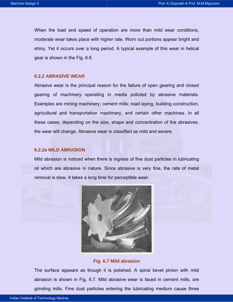
6.2.2a MILD ABRASION
Mild abrasion is noticed when there is ingress of fine dust particles in lubricating
oil which are abrasive in nature. Since abrasive is very fine, the rate of metal
removal is slow. It takes a long time for perceptible wear.
Fig. 6.7 Mild abrasion
The surface appears as though it is polished. A spiral bevel pinion with mild
abrasion is shown in Fig. 6.7. Mild abrasive wear is faced in cement mills, ore
grinding mills. Fine dust particles entering the lubricating medium cause three
Machine Design II Prof. K.Gopinath & Prof. M.M.Mayuram
Indian Institute of Technology Madras
body abrasions. The prior machining marks disappear and surface appears
highly polished as shown in Fig.. 6.8. Noticeable wear occurs only over a long
time. Sealing improvement and slight pressurization of the gear box with air can
reduce the entry of dust particles and decrease this wear.
Fig. 6.8 Mild abrasion
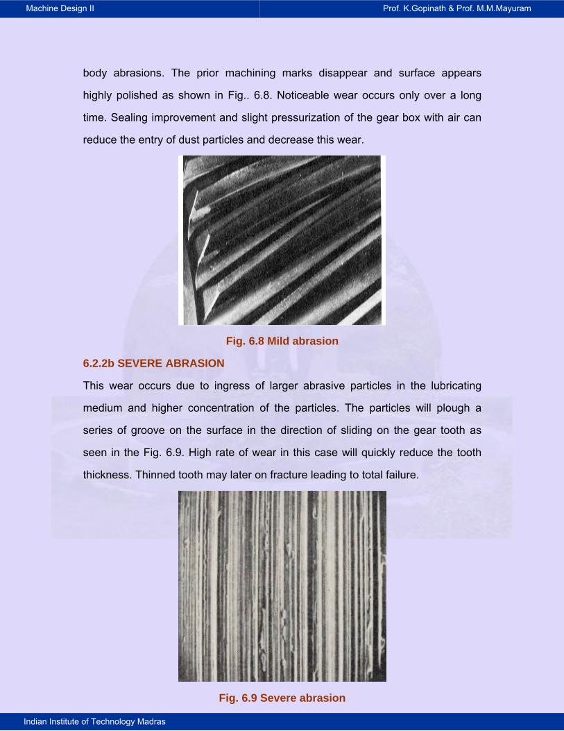
6.2.2b SEVERE ABRASION
This wear occurs due to ingress of larger abrasive particles in the lubricating
medium and higher concentration of the particles. The particles will plough a
series of groove on the surface in the direction of sliding on the gear tooth as
seen in the Fig. 6.9. High rate of wear in this case will quickly reduce the tooth
thickness. Thinned tooth may later on fracture leading to total failure.
Fig. 6.9 Severe abrasion
Machine Design II Prof. K.Gopinath & Prof. M.M.Mayuram
Indian Institute of Technology Madras
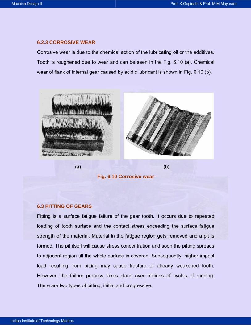
6.2.3 CORROSIVE WEAR
Corrosive wear is due to the chemical action of the lubricating oil or the additives.
Tooth is roughened due to wear and can be seen in the Fig. 6.10 (a). Chemical
wear of flank of internal gear caused by acidic lubricant is shown in Fig. 6.10 (b).
(a) (b)
Fig. 6.10 Corrosive wear
6.3 PITTING OF GEARS
Pitting is a surface fatigue failure of the gear tooth. It occurs due to repeated
loading of tooth surface and the contact stress exceeding the surface fatigue
strength of the material. Material in the fatigue region gets removed and a pit is
formed. The pit itself will cause stress concentration and soon the pitting spreads
to adjacent region till the whole surface is covered. Subsequently, higher impact
load resulting from pitting may cause fracture of already weakened tooth.
However, the failure process takes place over millions of cycles of running.
There are two types of pitting, initial and progressive.
Machine Design II Prof. K.Gopinath & Prof. M.M.Mayuram
Indian Institute of Technology Madras
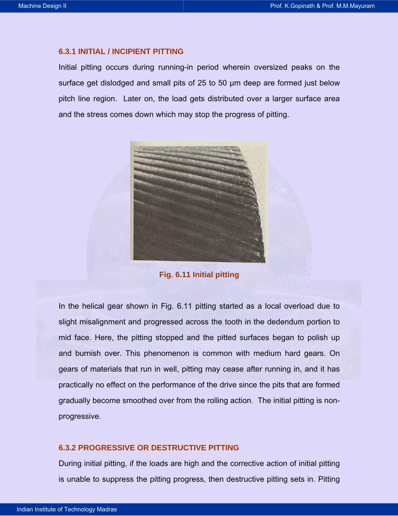
6.3.1 INITIAL / INCIPIENT PITTING
Initial pitting occurs during running-in period wherein oversized peaks on the
surface get dislodged and small pits of 25 to 50 μm deep are formed just below
pitch line region. Later on, the load gets distributed over a larger surface area
and the stress comes down which may stop the progress of pitting.
Fig. 6.11 Initial pitting
In the helical gear shown in Fig. 6.11 pitting started as a local overload due to
slight misalignment and progressed across the tooth in the dedendum portion to
mid face. Here, the pitting stopped and the pitted surfaces began to polish up
and burnish over. This phenomenon is common with medium hard gears. On
gears of materials that run in well, pitting may cease after running in, and it has
practically no effect on the performance of the drive since the pits that are formed
gradually become smoothed over from the rolling action. The initial pitting is non-
progressive.
6.3.2 PROGRESSIVE OR DESTRUCTIVE PITTING
During initial pitting, if the loads are high and the corrective action of initial pitting
is unable to suppress the pitting progress, then destructive pitting sets in. Pitting
Machine Design II Prof. K.Gopinath & Prof. M.M.Mayuram
Indian Institute of Technology Madras
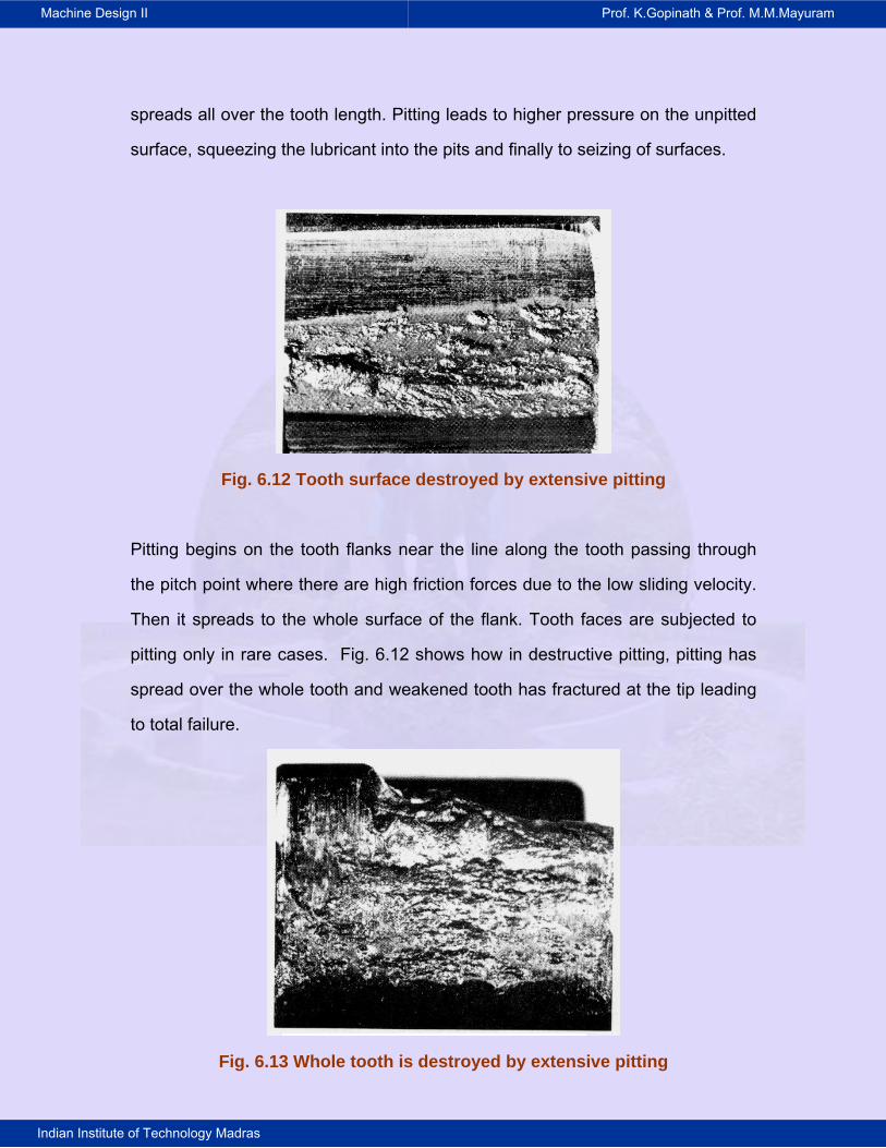
spreads all over the tooth length. Pitting leads to higher pressure on the unpitted
surface, squeezing the lubricant into the pits and finally to seizing of surfaces.
Fig. 6.12 Tooth surface destroyed by extensive pitting
Pitting begins on the tooth flanks near the line along the tooth passing through
the pitch point where there are high friction forces due to the low sliding velocity.
Then it spreads to the whole surface of the flank. Tooth faces are subjected to
pitting only in rare cases. Fig. 6.12 shows how in destructive pitting, pitting has
spread over the whole tooth and weakened tooth has fractured at the tip leading
to total failure.
Fig. 6.13 Whole tooth is destroyed by extensive pitting

Machine Design II Prof. K.Gopinath & Prof. M.M.Mayuram
Indian Institute of Technology Madras
6.3.2a FLAKING / SPALLING
In surface-hardened gears, the variable stresses in the underlying layer may lead
to surface fatigue and result in flaking (spalling) of material from the surface as
shown in Fig. 6.14.
(a)
(b)
Fig. 6.14 Flaking / Spalling
Machine Design II Prof. K.Gopinath & Prof. M.M.Mayuram
Indian Institute of Technology Madras
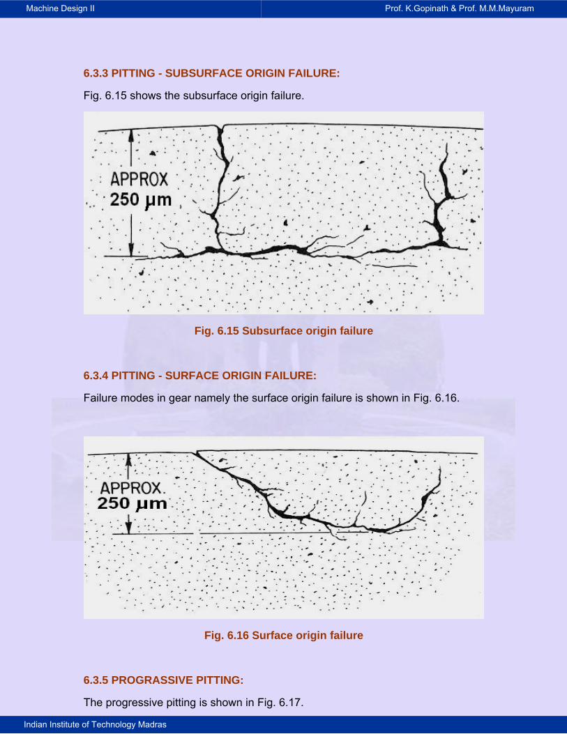
6.3.3 PITTING - SUBSURFACE ORIGIN FAILURE:
Fig. 6.15 shows the subsurface origin failure.
Fig. 6.15 Subsurface origin failure
6.3.4 PITTING - SURFACE ORIGIN FAILURE:
Failure modes in gear namely the surface origin failure is shown in Fig. 6.16.
Fig. 6.16 Surface origin failure
6.3.5 PROGRASSIVE PITTING:
The progressive pitting is shown in Fig. 6.17.
Machine Design II Prof. K.Gopinath & Prof. M.M.Mayuram
Indian Institute of Technology Madras
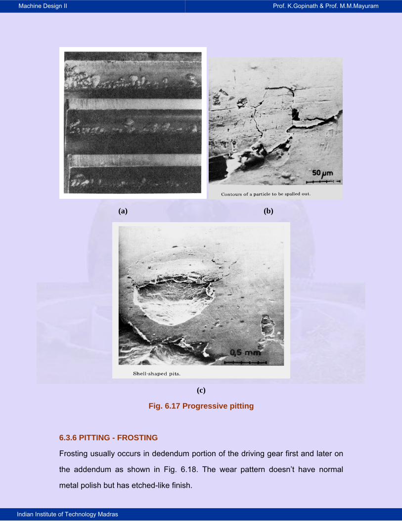
(a) (b)
(c)
Fig. 6.17 Progressive pitting
6.3.6 PITTING - FROSTING
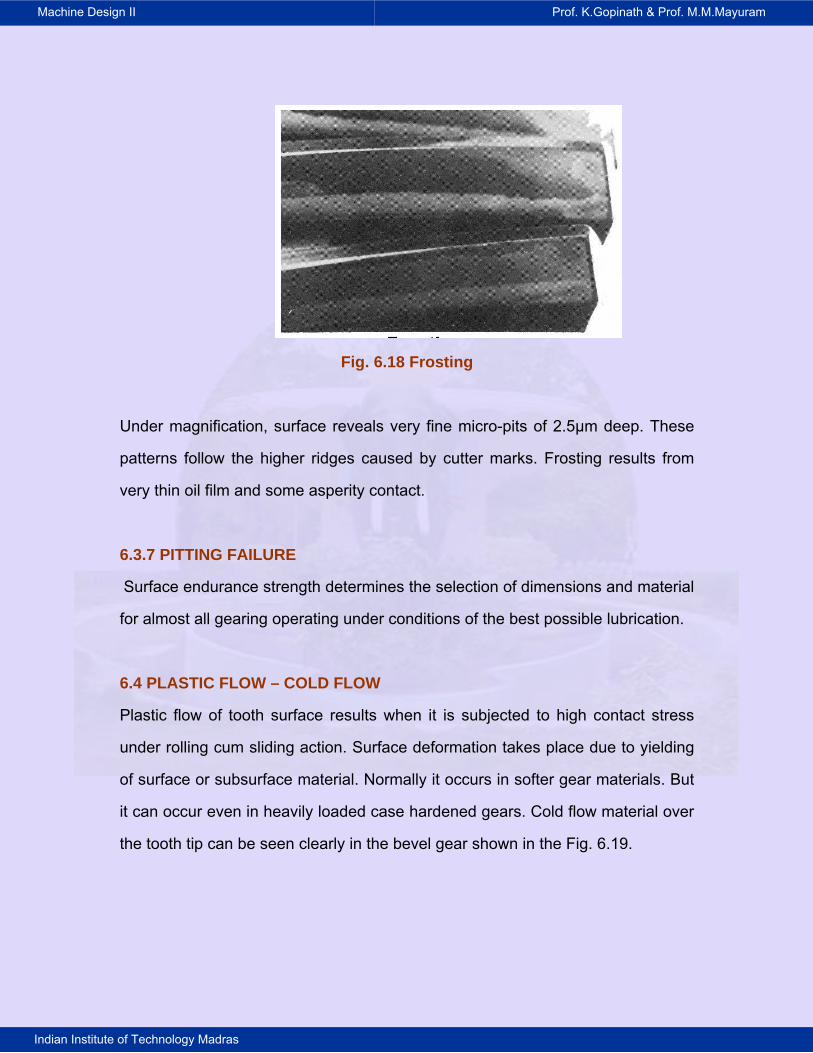
Frosting usually occurs in dedendum portion of the driving gear first and later on
the addendum as shown in Fig. 6.18. The wear pattern doesn’t have normal
metal polish but has etched-like finish.
Machine Design II Prof. K.Gopinath & Prof. M.M.Mayuram
Indian Institute of Technology Madras
Fig. 6.18 Frosting
Under magnification, surface reveals very fine micro-pits of 2.5μm deep. These
patterns follow the higher ridges caused by cutter marks. Frosting results from
very thin oil film and some asperity contact.
6.3.7 PITTING FAILURE
Surface endurance strength determines the selection of dimensions and material
for almost all gearing operating under conditions of the best possible lubrication.
6.4 PLASTIC FLOW – COLD FLOW
Plastic flow of tooth surface results when it is subjected to high contact stress
under rolling cum sliding action. Surface deformation takes place due to yielding
of surface or subsurface material. Normally it occurs in softer gear materials. But
it can occur even in heavily loaded case hardened gears. Cold flow material over
the tooth tip can be seen clearly in the bevel gear shown in the Fig. 6.19.
Machine Design II Prof. K.Gopinath & Prof. M.M.Mayuram
Indian Institute of Technology Madras
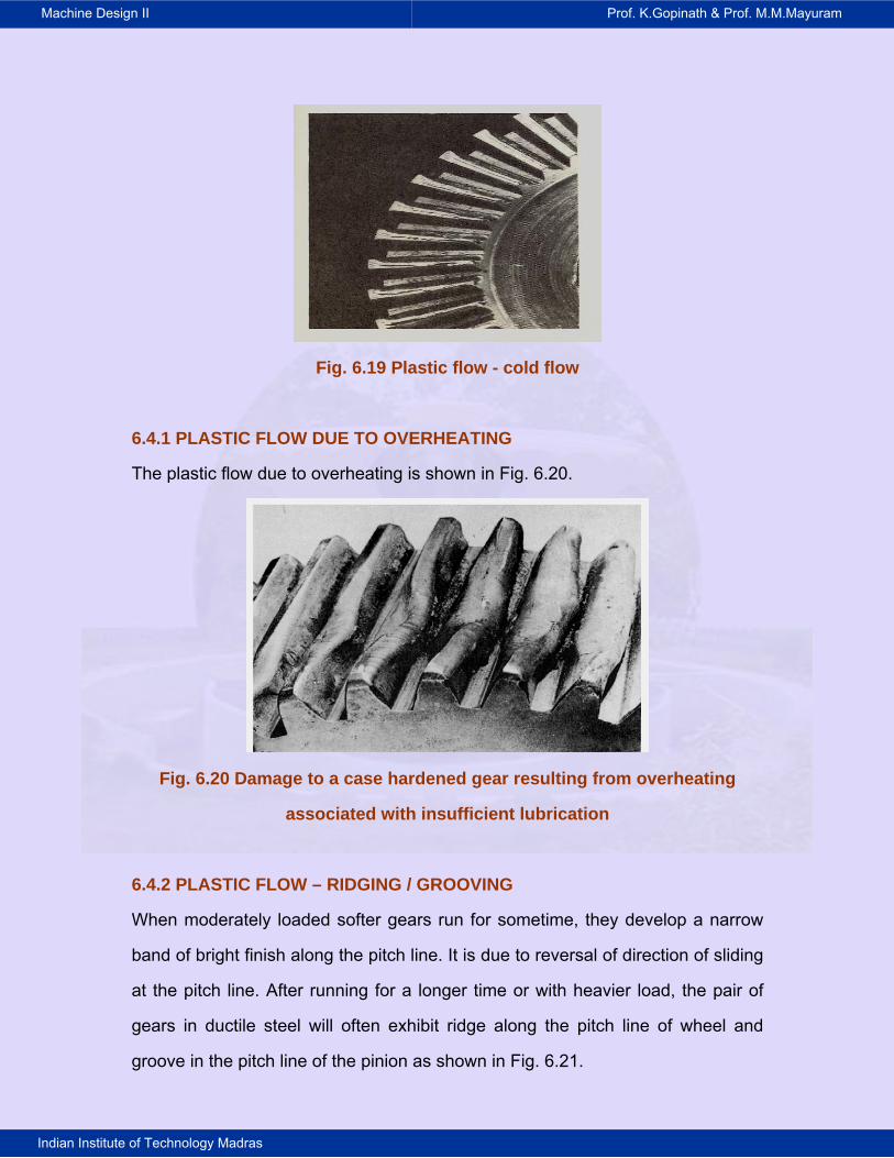
Fig. 6.19 Plastic flow - cold flow
6.4.1 PLASTIC FLOW DUE TO OVERHEATING
The plastic flow due to overheating is shown in Fig. 6.20.
Fig. 6.20 Damage to a case hardened gear resulting from overheating
associated with insufficient lubrication
6.4.2 PLASTIC FLOW – RIDGING / GROOVING
When moderately loaded softer gears run for sometime, they develop a narrow
band of bright finish along the pitch line. It is due to reversal of direction of sliding
at the pitch line. After running for a longer time or with heavier load, the pair of
gears in ductile steel will often exhibit ridge along the pitch line of wheel and
groove in the pitch line of the pinion as shown in Fig. 6.21.
Machine Design II Prof. K.Gopinath & Prof. M.M.Mayuram
Indian Institute of Technology Madras
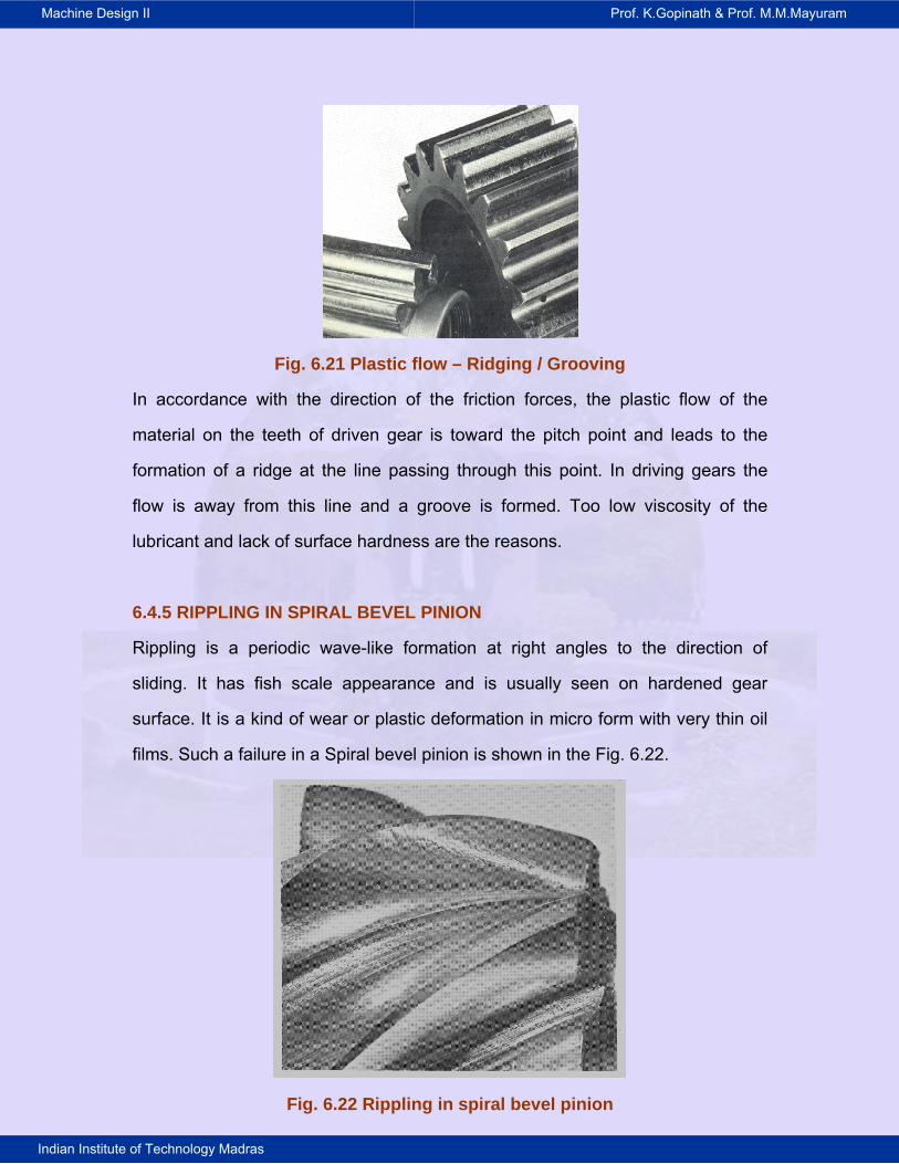
Fig. 6.21 Plastic flow – Ridging / Grooving
In accordance with the direction of the friction forces, the plastic flow of the
material on the teeth of driven gear is toward the pitch point and leads to the
formation of a ridge at the line passing through this point. In driving gears the
flow is away from this line and a groove is formed. Too low viscosity of the
lubricant and lack of surface hardness are the reasons.
6.4.5 RIPPLING IN SPIRAL BEVEL PINION
Rippling is a periodic wave-like formation at right angles to the direction of
sliding. It has fish scale appearance and is usually seen on hardened gear
surface. It is a kind of wear or plastic deformation in micro form with very thin oil
films. Such a failure in a Spiral bevel pinion is shown in the Fig. 6.22.
Fig. 6.22 Rippling in spiral bevel pinion
Machine Design II Prof. K.Gopinath & Prof. M.M.Mayuram
Indian Institute of Technology Madras
6.5 TOOTH FRACTURE
Tooth fracture is the most dangerous kind of gear failure and leads to
disablement of the drive and frequently to damage of other components (shafts,
bearings, etc.) by pieces of the broken teeth. Tooth breakage may be the result
of high overloads of either impact or static in nature, repeated overloads causing
low-cycle fatigue, or multiple repeated loads leading to high cycle fatigue of the
material.
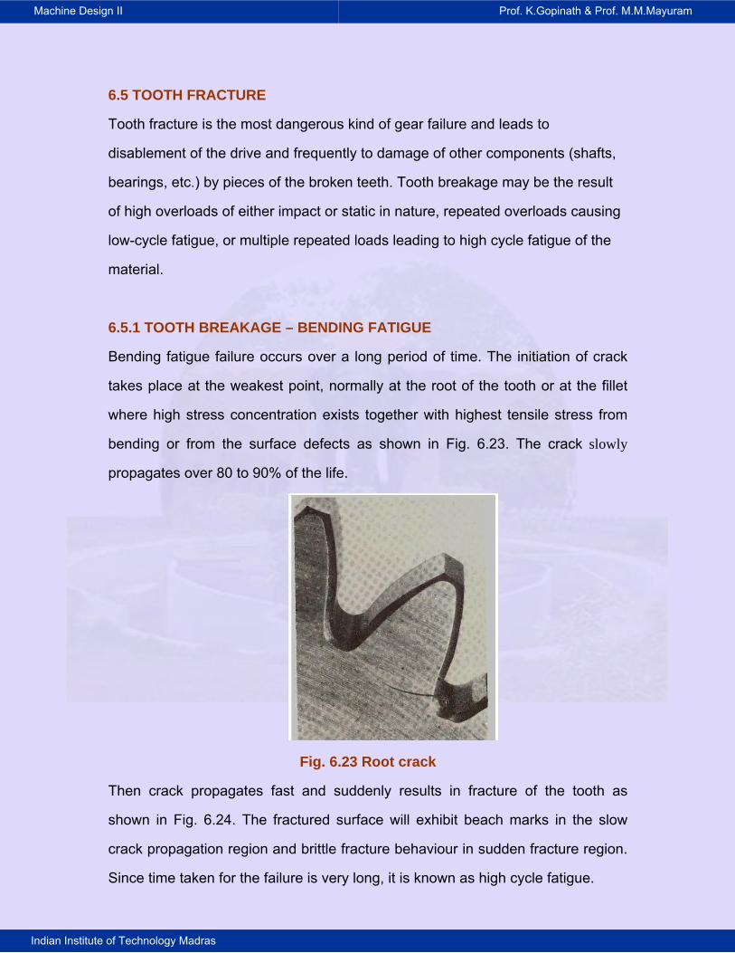
6.5.1 TOOTH BREAKAGE – BENDING FATIGUE
Bending fatigue failure occurs over a long period of time. The initiation of crack
takes place at the weakest point, normally at the root of the tooth or at the fillet
where high stress concentration exists together with highest tensile stress from
bending or from the surface defects as shown in Fig. 6.23. The crack slowly
propagates over 80 to 90% of the life.
Fig. 6.23 Root crack
Then crack propagates fast and suddenly results in fracture of the tooth as
shown in Fig. 6.24. The fractured surface will exhibit beach marks in the slow
crack propagation region and brittle fracture behaviour in sudden fracture region.
Since time taken for the failure is very long, it is known as high cycle fatigue.

Machine Design II Prof. K.Gopinath & Prof. M.M.Mayuram
Indian Institute of Technology Madras
Fig. 6.24 Tooth breakage
6.5.2 TOOTH BREAKAGE – HIGH CYCLE FATIGUE
The tooth breakage in case of high cycle fatigue is shown in Fig. 6.25.
Fig. 6.25 High cycle fatigue
Machine Design II Prof. K.Gopinath & Prof. M.M.Mayuram
Indian Institute of Technology Madras
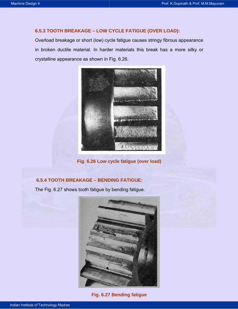
6.5.3 TOOTH BREAKAGE – LOW CYCLE FATIGUE (OVER LOAD):
Overload breakage or short (low) cycle fatigue causes stringy fibrous appearance
in broken ductile material. In harder materials this break has a more silky or
crystalline appearance as shown in Fig. 6.26.
Fig. 6.26 Low cycle fatigue (over load)
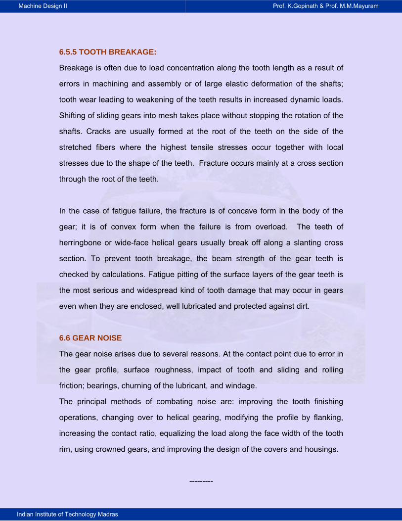
6.5.4 TOOTH BREAKAGE – BENDING FATIGUE:
The Fig. 6.27 shows tooth fatigue by bending fatigue.
Fig. 6.27 Bending fatigue
Machine Design II Prof. K.Gopinath & Prof. M.M.Mayuram
Indian Institute of Technology Madras
6.5.5 TOOTH BREAKAGE:
Breakage is often due to load concentration along the tooth length as a result of
errors in machining and assembly or of large elastic deformation of the shafts;
tooth wear leading to weakening of the teeth results in increased dynamic loads.
Shifting of sliding gears into mesh takes place without stopping the rotation of the
shafts. Cracks are usually formed at the root of the teeth on the side of the
stretched fibers where the highest tensile stresses occur together with local
stresses due to the shape of the teeth. Fracture occurs mainly at a cross section
through the root of the teeth.
In the case of fatigue failure, the fracture is of concave form in the body of the
gear; it is of convex form when the failure is from overload. The teeth of
herringbone or wide-face helical gears usually break off along a slanting cross
section. To prevent tooth breakage, the beam strength of the gear teeth is
checked by calculations. Fatigue pitting of the surface layers of the gear teeth is
the most serious and widespread kind of tooth damage that may occur in gears
even when they are enclosed, well lubricated and protected against dirt.
6.6 GEAR NOISE
The gear noise arises due to several reasons. At the contact point due to error in
the gear profile, surface roughness, impact of tooth and sliding and rolling
friction; bearings, churning of the lubricant, and windage.
The principal methods of combating noise are: improving the tooth finishing
operations, changing over to helical gearing, modifying the profile by flanking,
increasing the contact ratio, equalizing the load along the face width of the tooth
rim, using crowned gears, and improving the design of the covers and housings.
---------