Embed Size (px)
Citation preview
Lecture 5: 3D Rendering Pipeline (II)
Prof. Hsien-Hsin Sean LeeSchool of Electrical and Computer
EngineeringGeorgia Institute of Technology
2
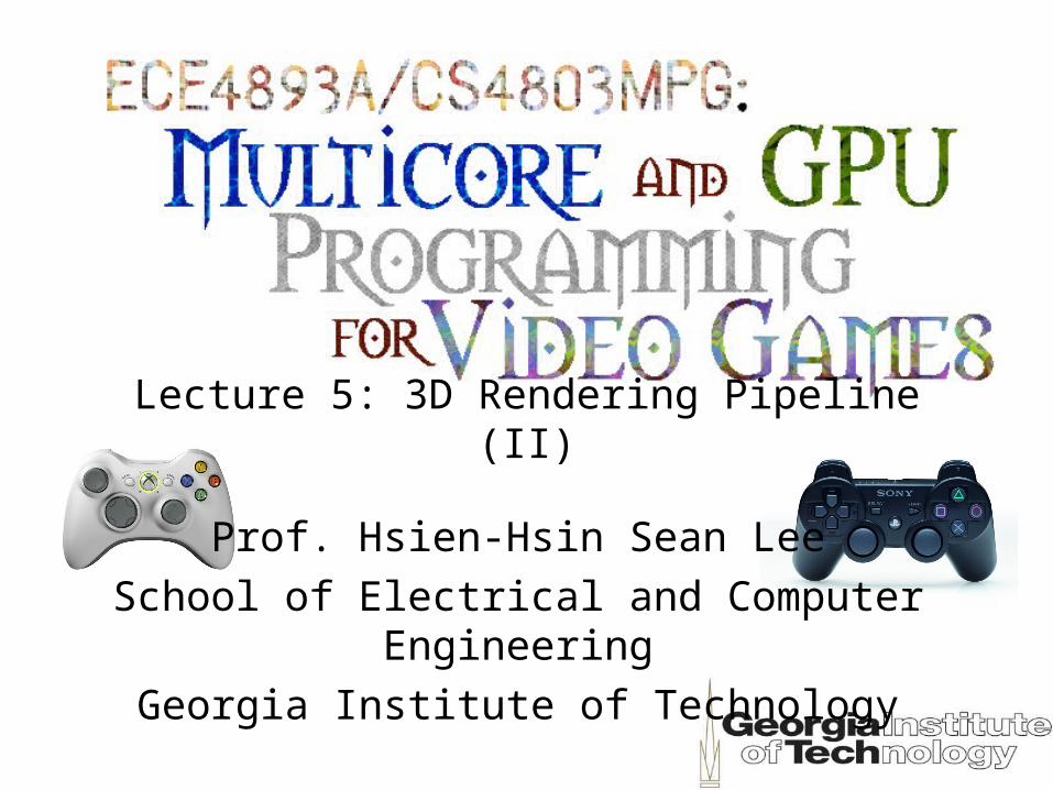
Parallel Projection
Viewer’s position
View plane
• Project from 3D space to viewer’s 2D space
3
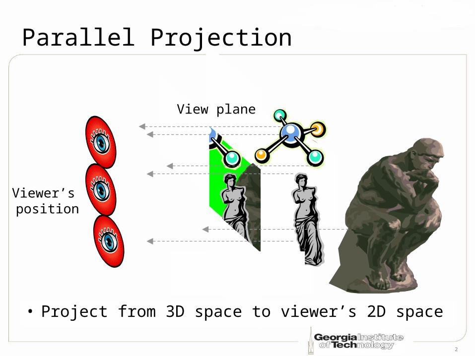
Perspective Projection
• The farther the object is, the smaller it appears• Some photo editing software allows you to
perform “Perspective Correction”
Viewer’s position
View plane
4
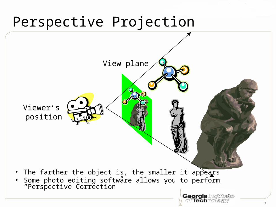
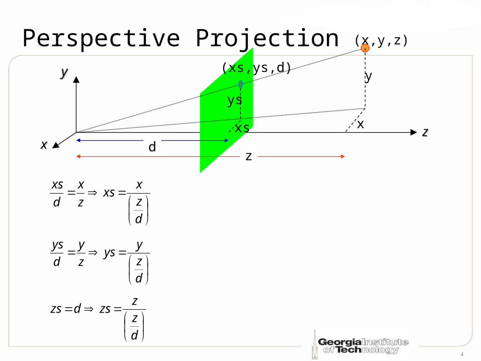
Perspective Projection
dzx
xsz
x
d
xs
dzz
zsdzs
xx
yy
zz
(x,y,z)
(xs,ys,d)
dxs
ys
x
y
z
dzy
ysz
y
d
ys
5
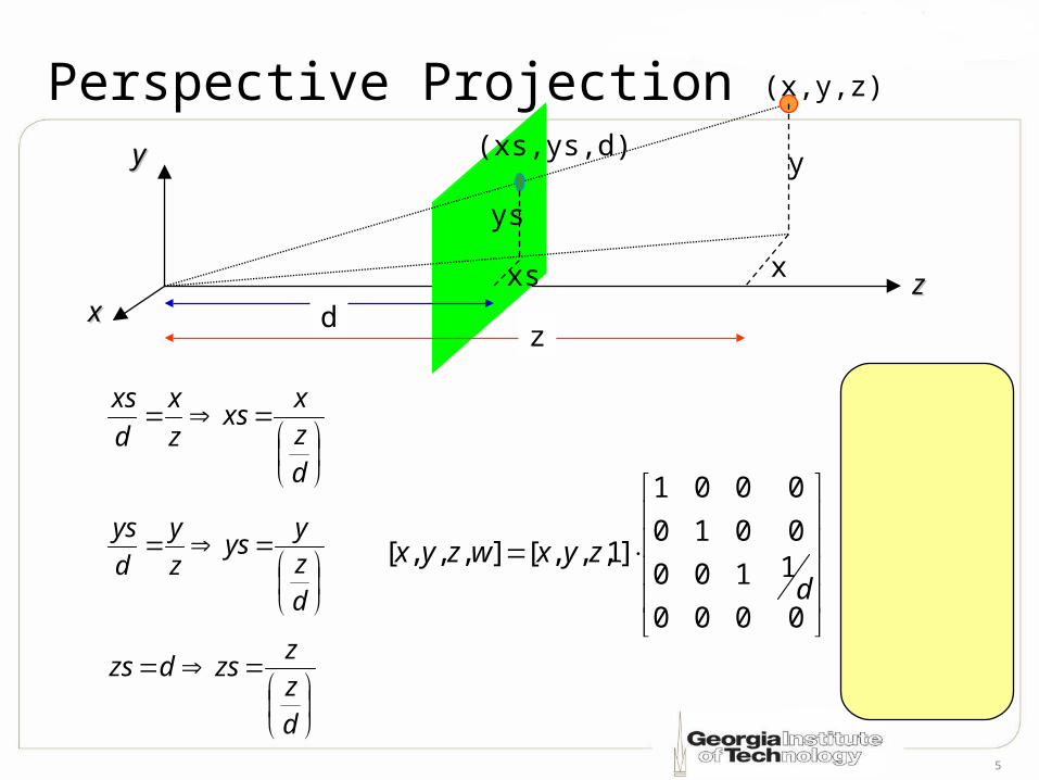
Perspective Projection
0000
1100
0010
0001
]1,,,[],,,[d
zyxwzyx
xx
yy
zz
(x,y,z)
(xs,ys,d)
dxs
ys
x
y
z
dzx
xsz
x
d
xs
dzz
zsdzs
dzy
ysz
y
d
ys
w
xxs
w
zzs
w
yys
6
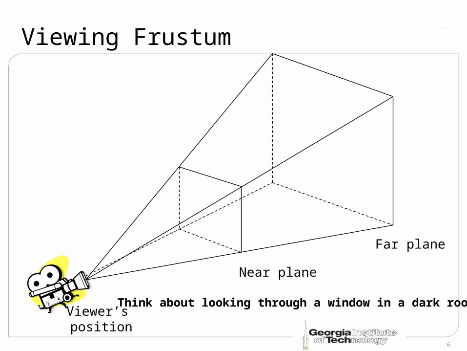
Viewing Frustum
Far plane
Viewer’s position
Near plane
Think about looking through a window in a dark room
7
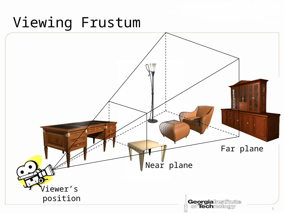
Viewing Frustum
Near plane
Far plane
Viewer’s position
8
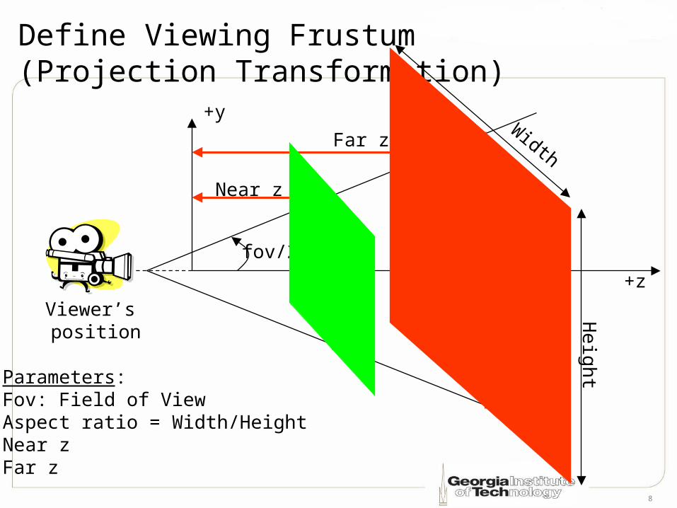
Define Viewing Frustum(Projection Transformation)
Viewer’s position
+z
Parameters:Fov: Field of ViewAspect ratio = Width/HeightNear zFar z
fov/2
+y
Far z
Near z
Width
He
ight
9
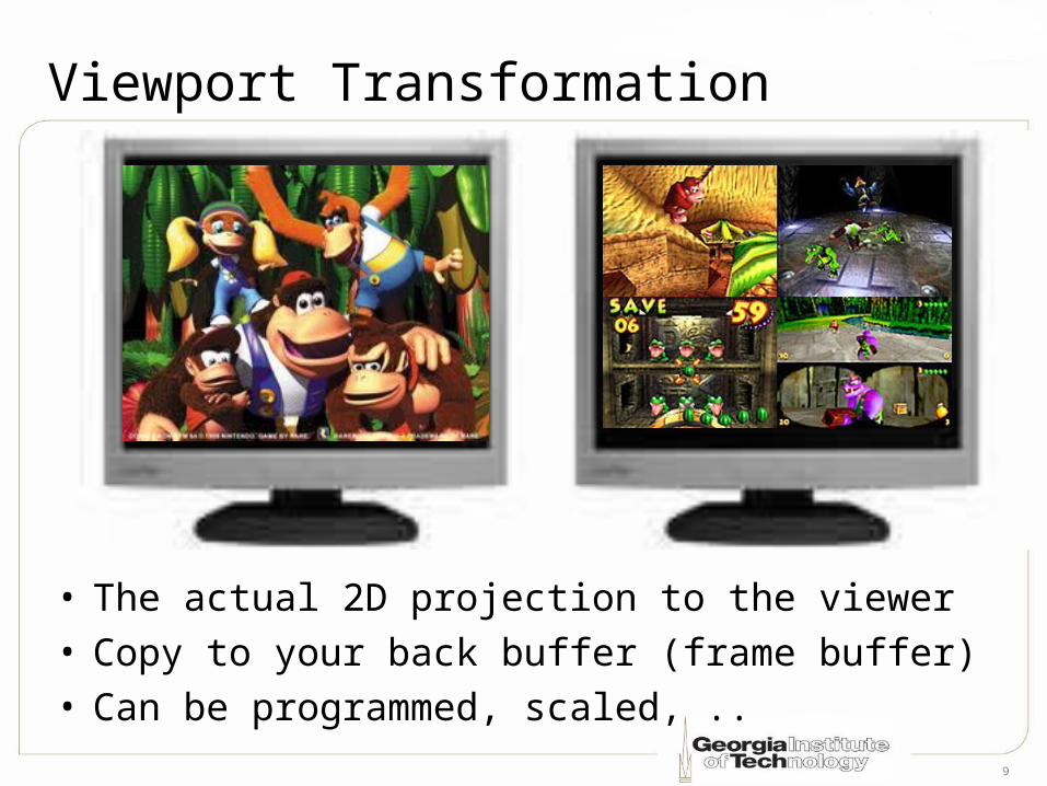
Viewport Transformation
• The actual 2D projection to the viewer• Copy to your back buffer (frame buffer)• Can be programmed, scaled, ..
10
Other Geometry Optimizations• Backface Culling
• Clipping
• Hidden surface removal (Occlusion)
11
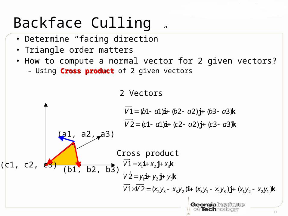
Backface Culling• Determine “facing direction”• Triangle order matters• How to compute a normal vector for 2 given vectors?
– Using Cross product Cross product of 2 given vectors
(c1, c2, c3) (b1, b2, b3)
(a1, a2, a3)
kji
kji
kji
)()()(21
2
1
122131132332
321
321
yxyxyxyxyxyxVV
yyyV
xxxV
Cross product
kji
kji
)33()22()11(2
)33()22()11(1
acacacV
abababV
2 Vectors
12
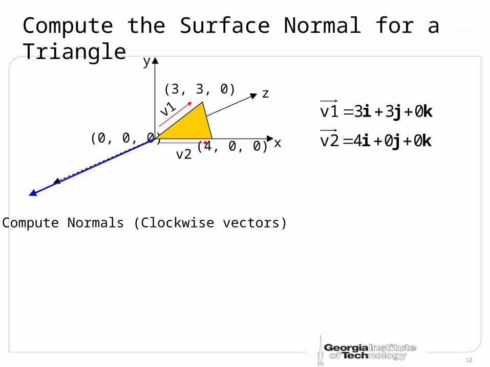
Compute the Surface Normal for a Triangle
(0, 0, 0) (4, 0, 0)
(3, 3, 0)
kji
kji
004v2
033v1
Compute Normals (Clockwise vectors)
v1
v2x
z
y
13
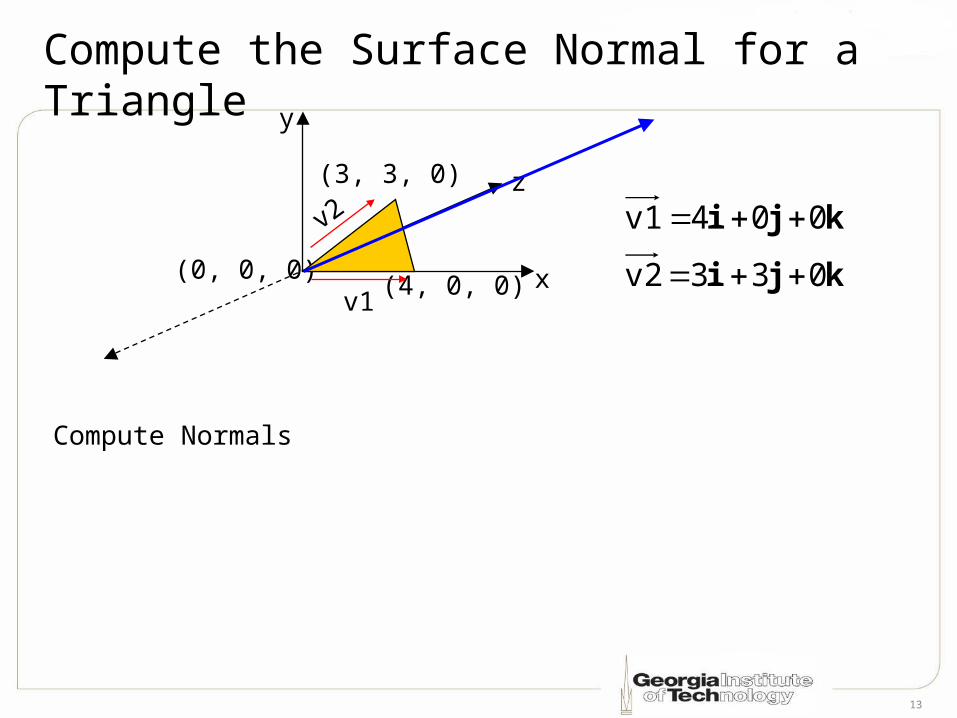
Compute the Surface Normal for a Triangle
(0, 0, 0) (4, 0, 0)
(3, 3, 0)
kji
kji
033v2
004v1
Compute Normals
v2
v1x
z
y
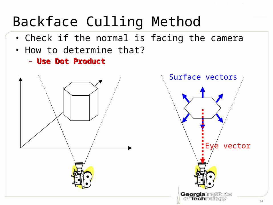
14
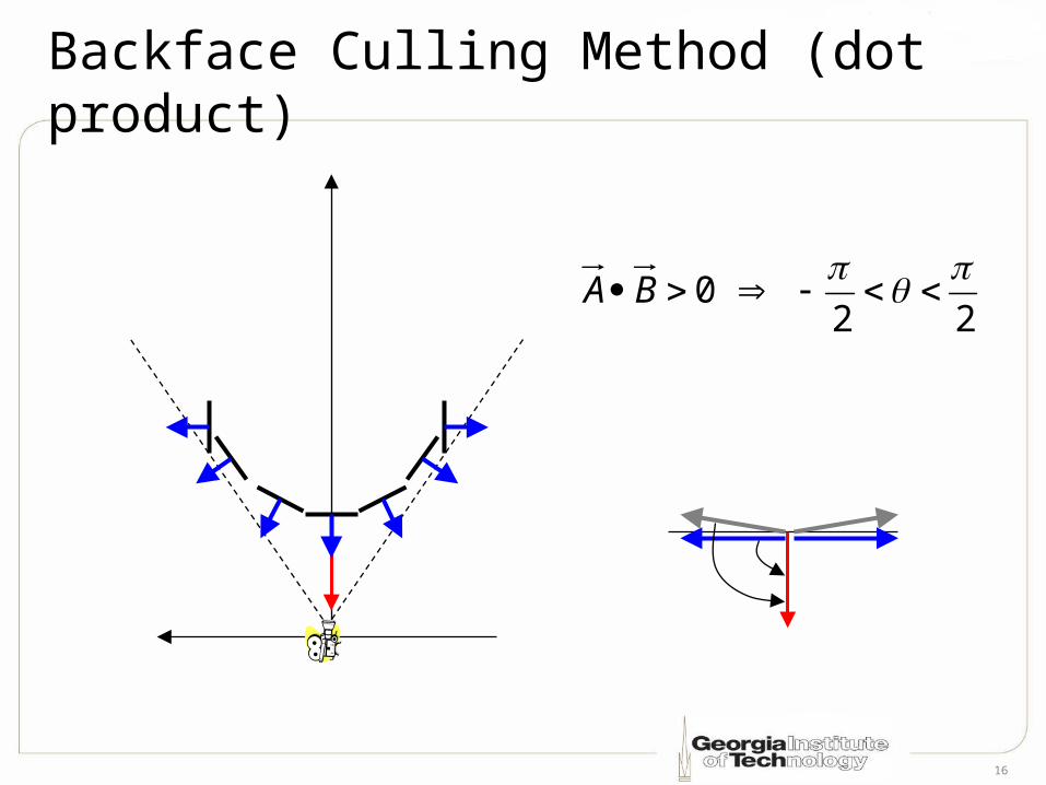
Backface Culling Method• Check if the normal is facing the camera• How to determine that?
– Use Dot ProductUse Dot Product
Surface vectors
Eye vector
15
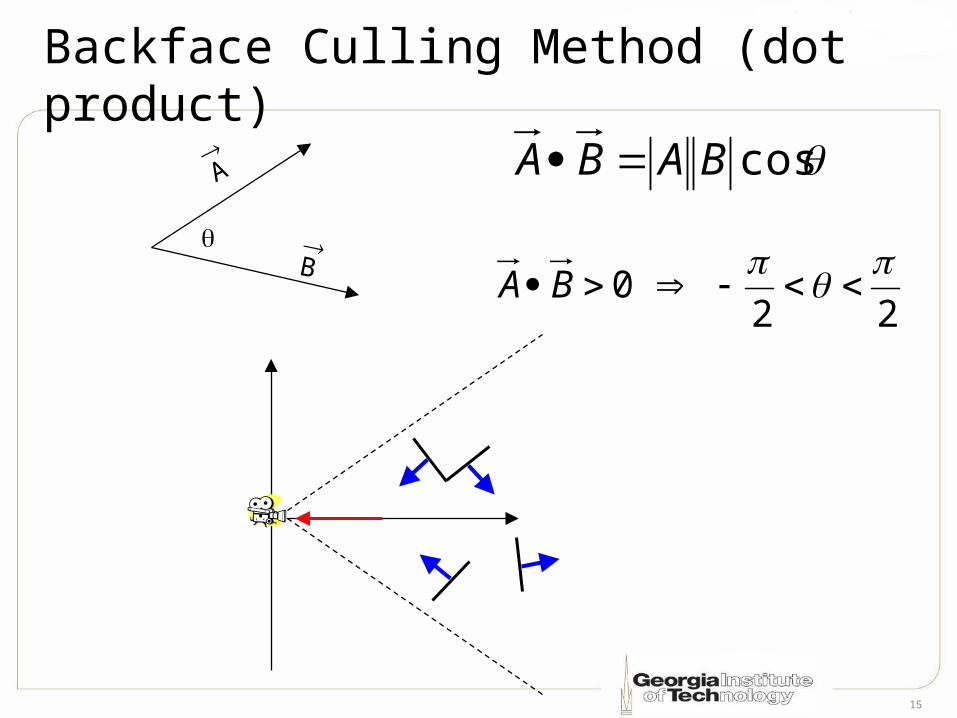
Backface Culling Method (dot product)
A
B
cosBABA
22
0
BA
16
Backface Culling Method (dot product)
22
0
BA
17
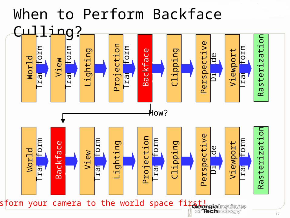
When to Perform Backface Culling?
Clip
ping
Pers
pect
ive D
ivide
View
port
Tran
sfor
m
Rast
eriza
tion
Proj
ectio
n Tr
ansf
orm
Wor
ld T
rans
form
View
Tra
nsfo
rm
Ligh
ting
Back
face
Cul
ling
Clip
ping
Pers
pect
ive D
ivide
View
port
Tran
sfor
m
Rast
eriza
tion
Proj
ectio
n Tr
ansf
orm
Wor
ld T
rans
form
View
Tra
nsfo
rm
Ligh
ting
Back
face
Cul
ling
How?
Transform your camera to the world space first!
18
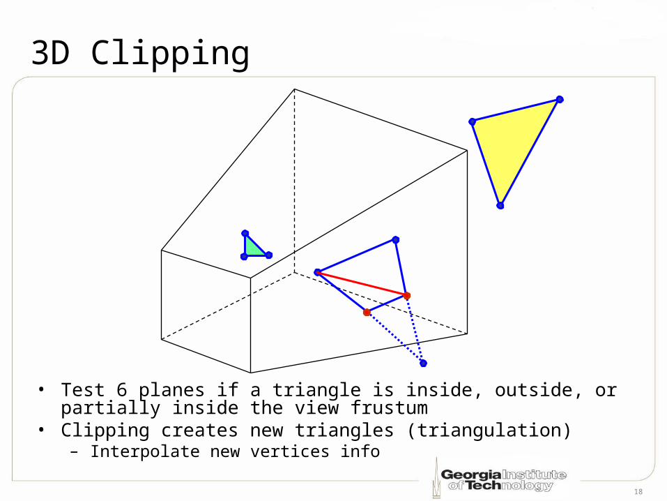
3D Clipping
• Test 6 planes if a triangle is inside, outside, or partially inside the view frustum
• Clipping creates new triangles (triangulation)– Interpolate new vertices info
19
How to Clip Against a Plane?• Test each vertex of a triangle
– Outside– Inside– Partially inside
• Incurred computation overhead• Save unnecessary computation (and
bandwidth) later• Need to know how to determine a plane• Need to know how to determine a
vertex is inside or outside a plane
20
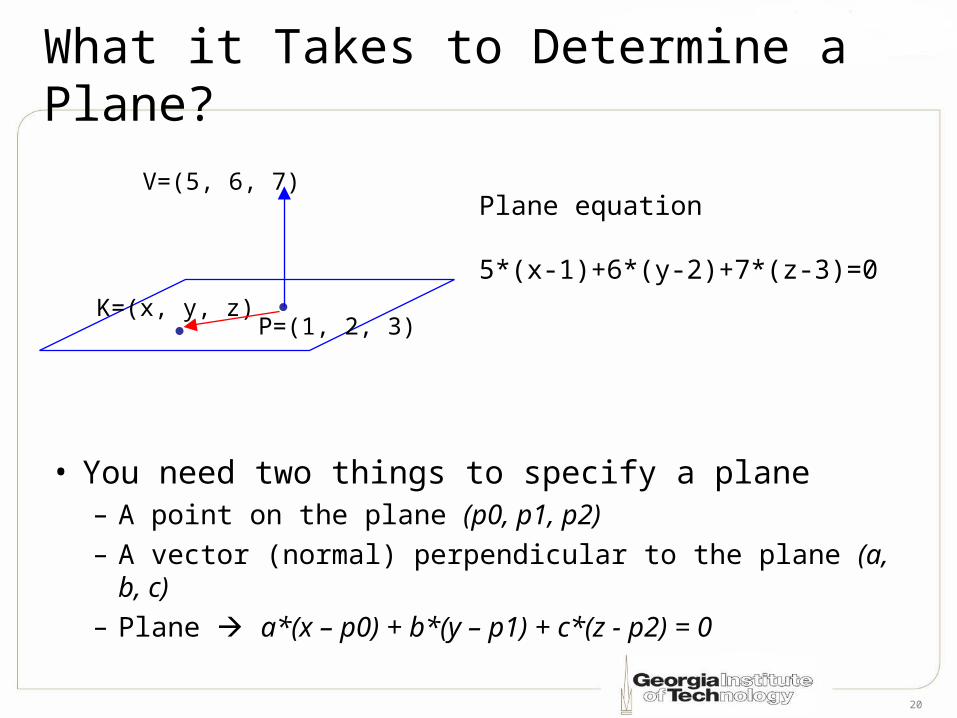
What it Takes to Determine a Plane?
• You need two things to specify a plane– A point on the plane (p0, p1, p2)– A vector (normal) perpendicular to the plane (a, b, c)– Plane a*(x – p0) + b*(y – p1) + c*(z - p2) = 0
V=(5, 6, 7)
P=(1, 2, 3)K=(x, y, z)
Plane equation
5*(x-1)+6*(y-2)+7*(z-3)=0
21
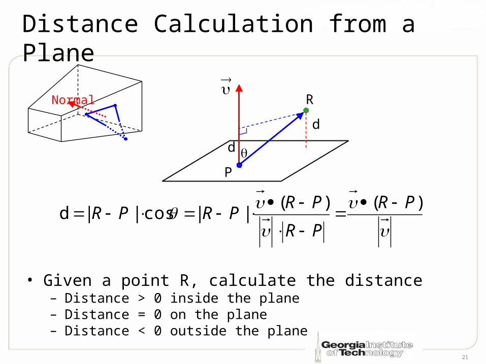
Distance Calculation from a Plane
• Given a point R, calculate the distance– Distance > 0 inside the plane– Distance = 0 on the plane– Distance < 0 outside the plane
Normal R
d
d
)()(
|| cos|| dPR
PR
PRPRPR
P
22
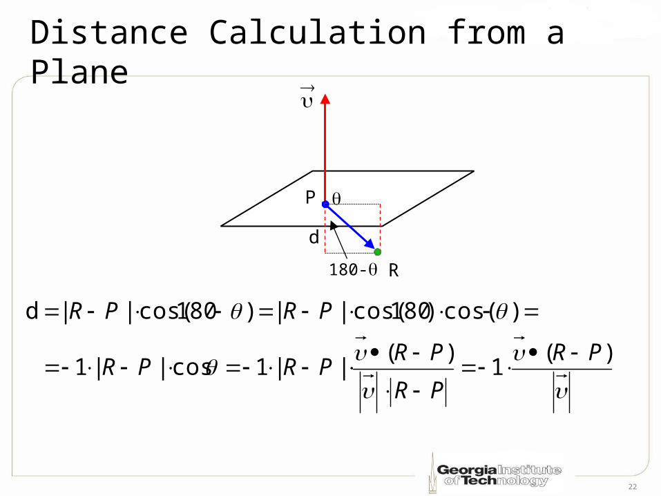
Distance Calculation from a Plane
R
d
)(1
)(||1cos||1
)cos()180cos(|| )180cos(|| d
PR
PR
PRPRPR
PRPR
P
180-
23
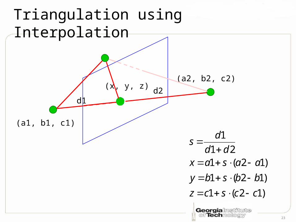
Triangulation using Interpolation
(a2, b2, c2)
(a1, b1, c1)
(x, y, z)
d1d2
)12(1
)12(1
)12(121
1
ccscz
bbsby
aasaxdd
ds
24
Illumination Models
• It won’t look 3D without lighting• Part of geometry processing• Illumination Types
– Ambient– Diffuse– Specular– Emissive
25
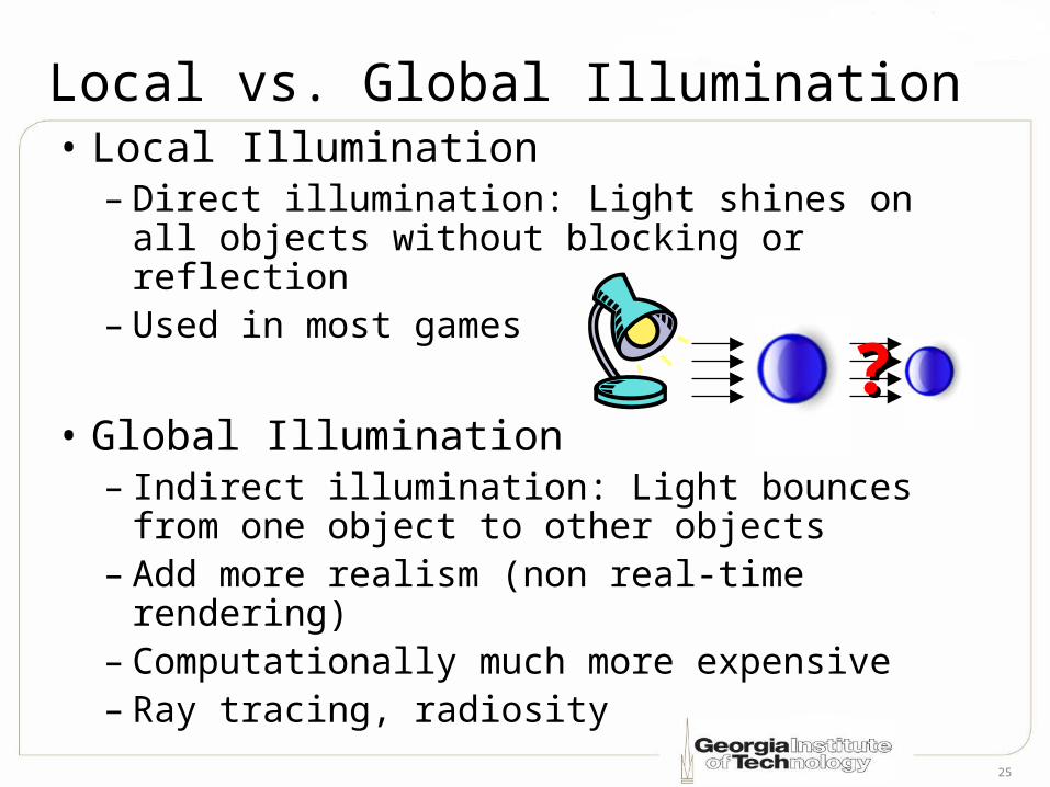
Local vs. Global Illumination• Local Illumination
– Direct illumination: Light shines on all objects without blocking or reflection
– Used in most games
• Global Illumination– Indirect illumination: Light bounces from
one object to other objects– Add more realism (non real-time
rendering)– Computationally much more expensive– Ray tracing, radiosity
??
26
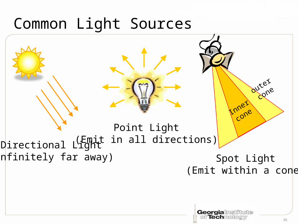
Common Light Sources
Directional Light(Infinitely far away)
Point Light(Emit in all directions)
Spot Light(Emit within a cone)
Inner
cone
outer
cone
27
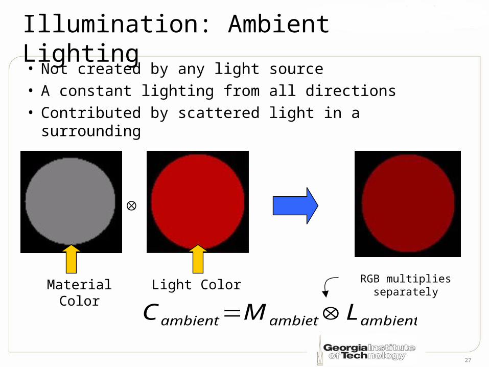
Illumination: Ambient Lighting• Not created by any light source• A constant lighting from all directions• Contributed by scattered light in a surrounding
ambientambietambient LMC
RGB multiplies separatelyMaterial Color Light Color
28
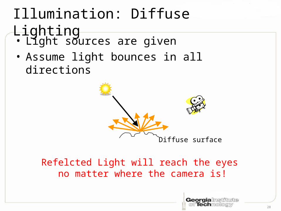
Illumination: Diffuse Lighting• Light sources are given• Assume light bounces in all directions
Refelcted Light will reach the eyes no matter where the camera is!
Diffuse surface
29
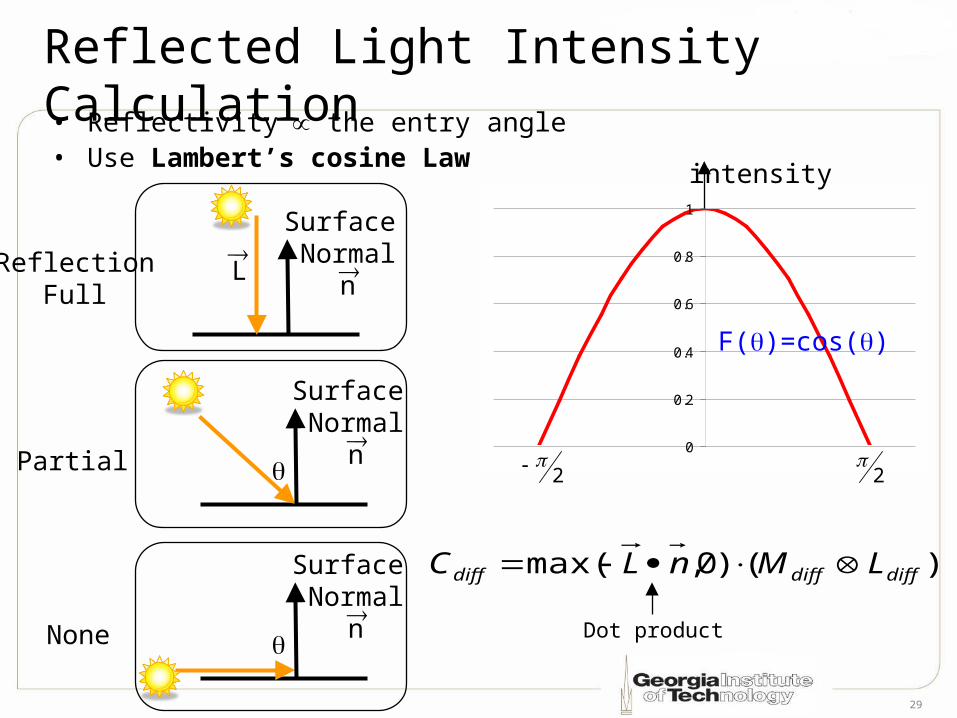
Reflected Light Intensity Calculation• Reflectivity the entry angle • Use Lambert’s cosine Law
0
0.2
0.4
0.6
0.8
1
2
intensity
F()=cos()
2
Surface Normal
n
Surface Normal
n
Surface Normal
n
)()0,max( diffdiffdiff LMnLC
Dot product
ReflectionFull
None
Partial
L
30
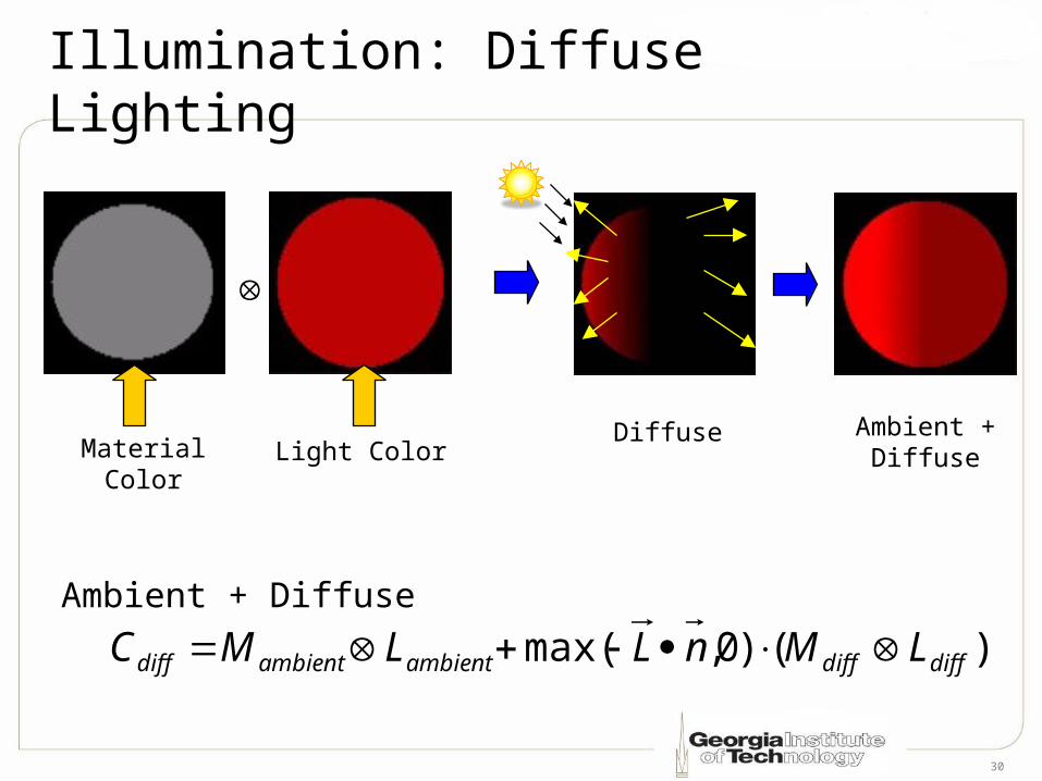
Diffuse
Illumination: Diffuse Lighting
Material Color Light ColorAmbient +
Diffuse
)()0,max( diffdiffambientambientdiff LMnLLMC Ambient + Diffuse
31
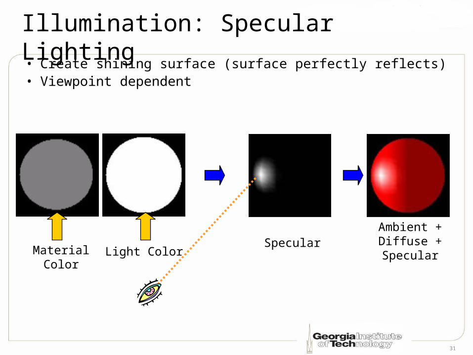
Illumination: Specular Lighting• Create shining surface (surface perfectly reflects)• Viewpoint dependent
Ambient +Diffuse +SpecularMaterial Color Light Color
Specular
32
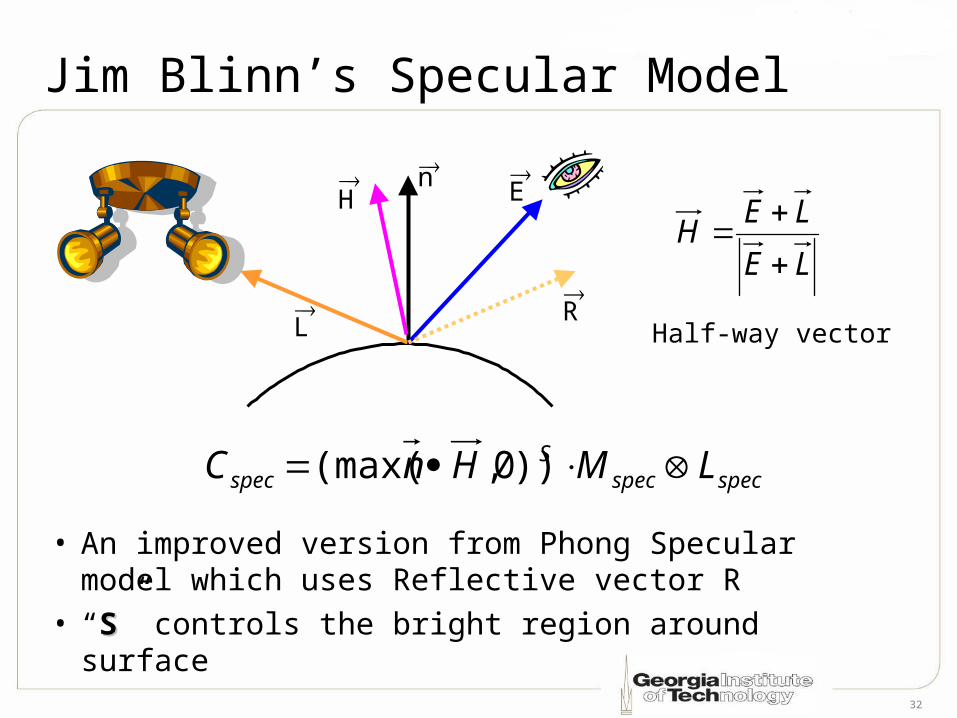
Jim Blinn’s Specular Model
• An improved version from Phong Specular model which uses Reflective vector R
• “SS” controls the bright region around surface
E
L
n
specspecS
spec LMHnC ))0,(max(
R
LE
LEH
Half-way vector
H
33
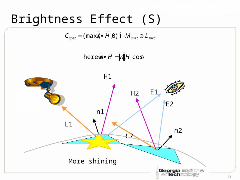
Brightness Effect (S)
cos here w
))0,(max(
HnHn
LMHnC specspecS
spec
L1
L2
n1
n2
H1
H2
More shining
E1
E2
34
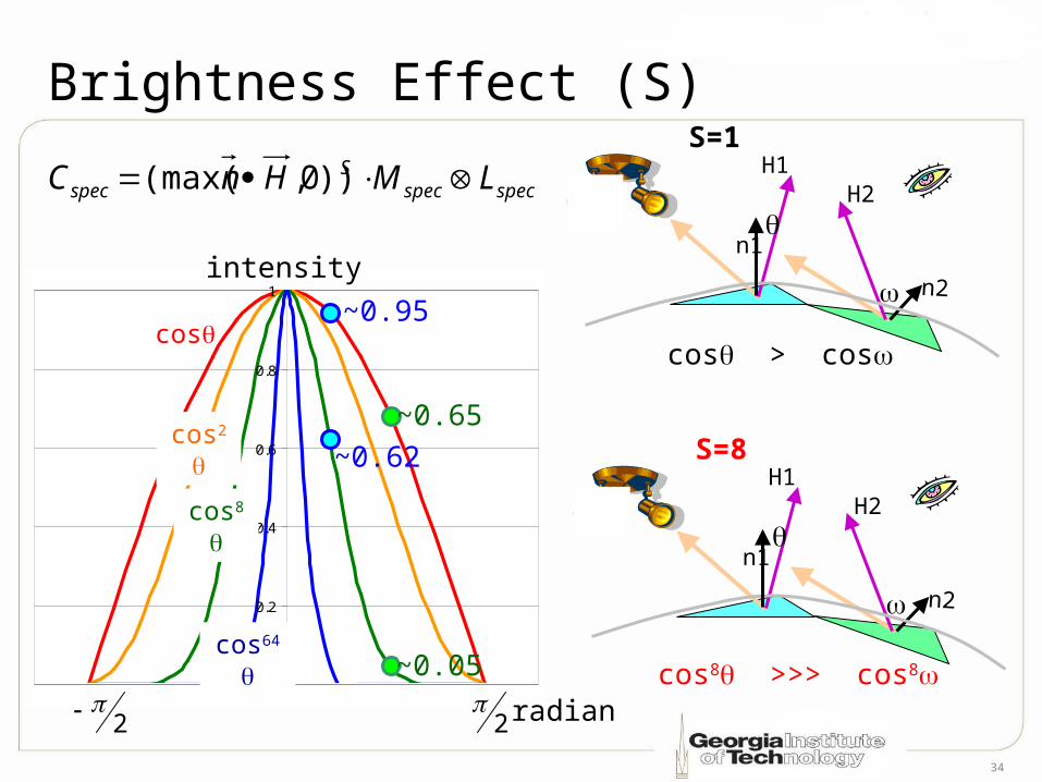
Brightness Effect (S)
0
0.2
0.4
0.6
0.8
1intensity
cos
cos2
cos8
cos64
2 2
specspecS
spec LMHnC ))0,(max(
cos > cos
~0.65
~0.95
cos8 >>> cos8
~0.62
n1
n2
H1H2
S=1
n1
n2
H1H2
S=8
~0.05
radian
35
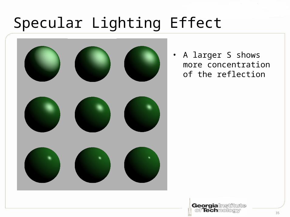
Specular Lighting Effect
• A larger S shows more concentration of the reflection
36
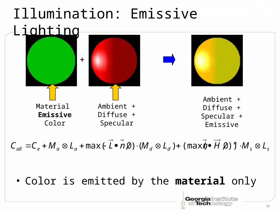
Illumination: Emissive Lighting
• Color is emitted by the material only
ssn
ddaaeall LMHnLMnLLMCC ))0,(max()()0,max(
Ambient +Diffuse +
Specular +Emissive
Material Emissive
Color
+
Ambient +Diffuse +Specular

37
Common Light Sources
Directional Light(Infinitely far away)
Point Light(Emit in all directions)
Spot Light(Emit within a cone)
Inner
cone
outer
cone
38
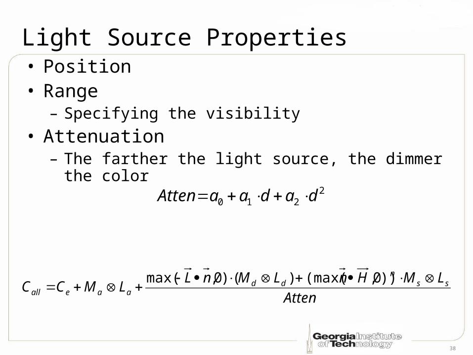
Light Source Properties• Position• Range
– Specifying the visibility
• Attenuation– The farther the light source, the dimmer the
color2
210 dadaaAtten
Atten
LMHnLMnLLMCC ss
ndd
aaeall
))0,(max()()0,max(
39
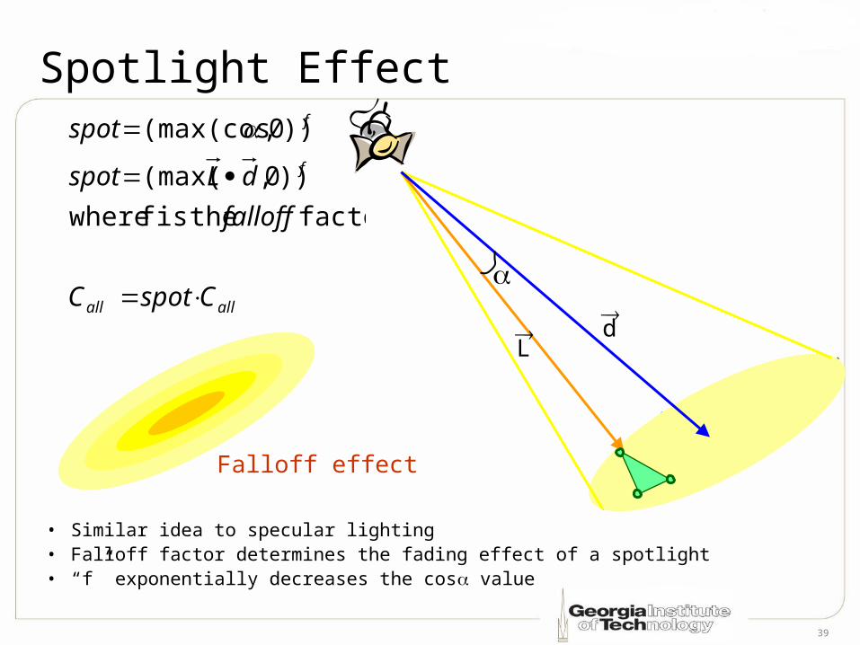
Falloff effect
Spotlight Effect
• Similar idea to specular lighting• Falloff factor determines the fading effect of a spotlight• “f” exponentially decreases the cos value
L d
allall
f
f
Cspot C
falloff
dLspot
spot
factor theis f where
))0,(max(
))0,(max(cos