Embed Size (px)
Citation preview
Lecture 4
Data Transmission Modes and Switching
Data Transmission & Switching 1-1
Agenda
Introduction to Data Transmission Modes
Parallel and Serial Transmission
Transmission Media
Guided and unguided media
Data Switching Techniques
Circuit Switching
Packet Switching
Data Transmission & Switching 1-2
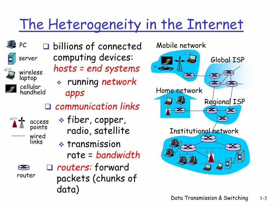
The Heterogeneity in the Internet
Data Transmission & Switching 1-3
billions of connected computing devices: hosts = end systems
running network apps Home network
Institutional network
Mobile network
Global ISP
Regional ISP
router
PC
server
wireless laptop
cellular handheld
wired links
access points
communication links
fiber, copper, radio, satellite
transmission rate = bandwidth
routers: forward packets (chunks of data)
Data Transmission Modes
How are data sent via computer networks and
related connecting wires/cables ?
Do we send 1 bit at a time ?
Do we group bits into larger groups ?
The transmission of binary data across a link
can be accomplished in either parallel or serial
mode
Data Transmission & Switching 1-4
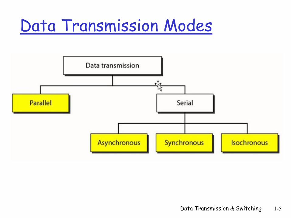
Data Transmission Modes
Data Transmission & Switching 1-5
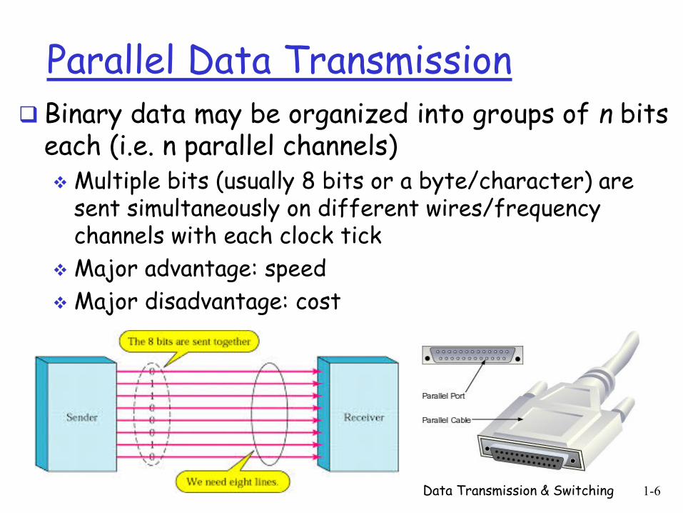
Parallel Data Transmission Binary data may be organized into groups of n bits
each (i.e. n parallel channels) Multiple bits (usually 8 bits or a byte/character) are
sent simultaneously on different wires/frequency channels with each clock tick
Major advantage: speed
Major disadvantage: cost
Data Transmission & Switching 1-6
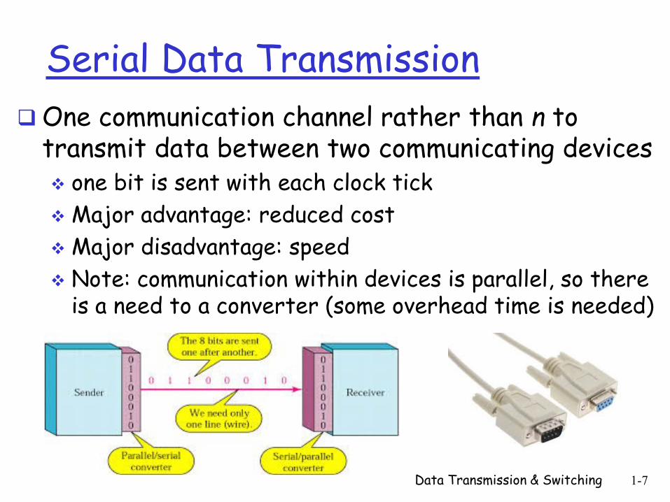
Serial Data Transmission
One communication channel rather than n to transmit data between two communicating devices one bit is sent with each clock tick
Major advantage: reduced cost
Major disadvantage: speed
Note: communication within devices is parallel, so there is a need to a converter (some overhead time is needed)
Data Transmission & Switching 1-7
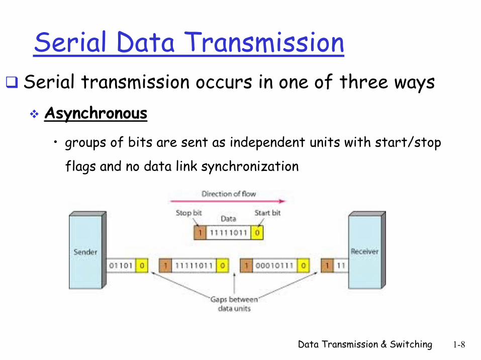
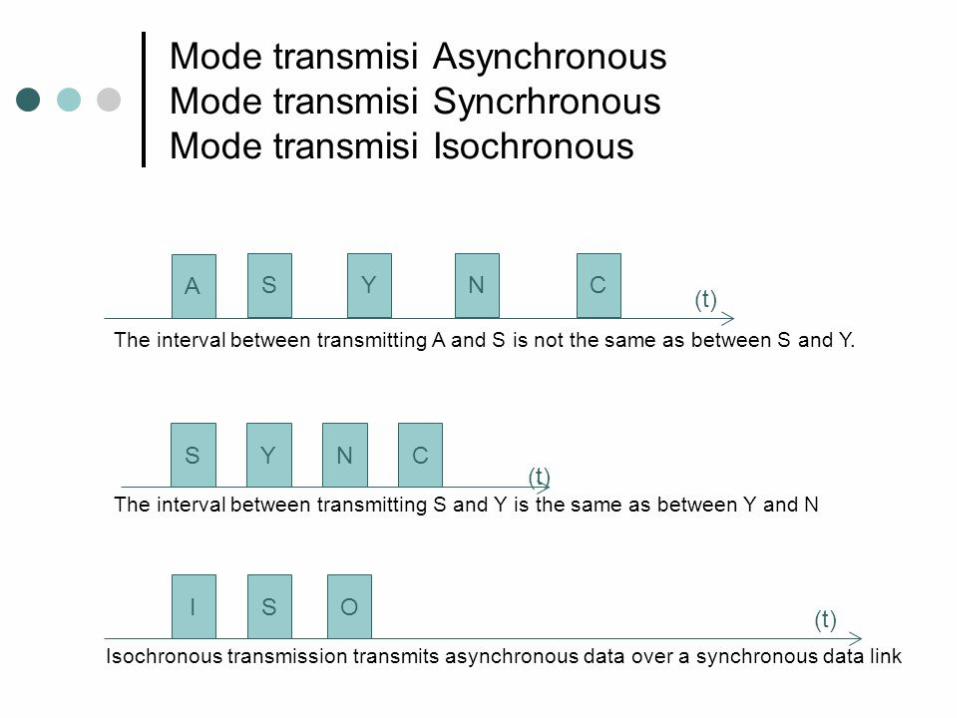
Serial Data Transmission
Serial transmission occurs in one of three ways
Asynchronous
• groups of bits are sent as independent units with start/stop
flags and no data link synchronization
Data Transmission & Switching 1-8
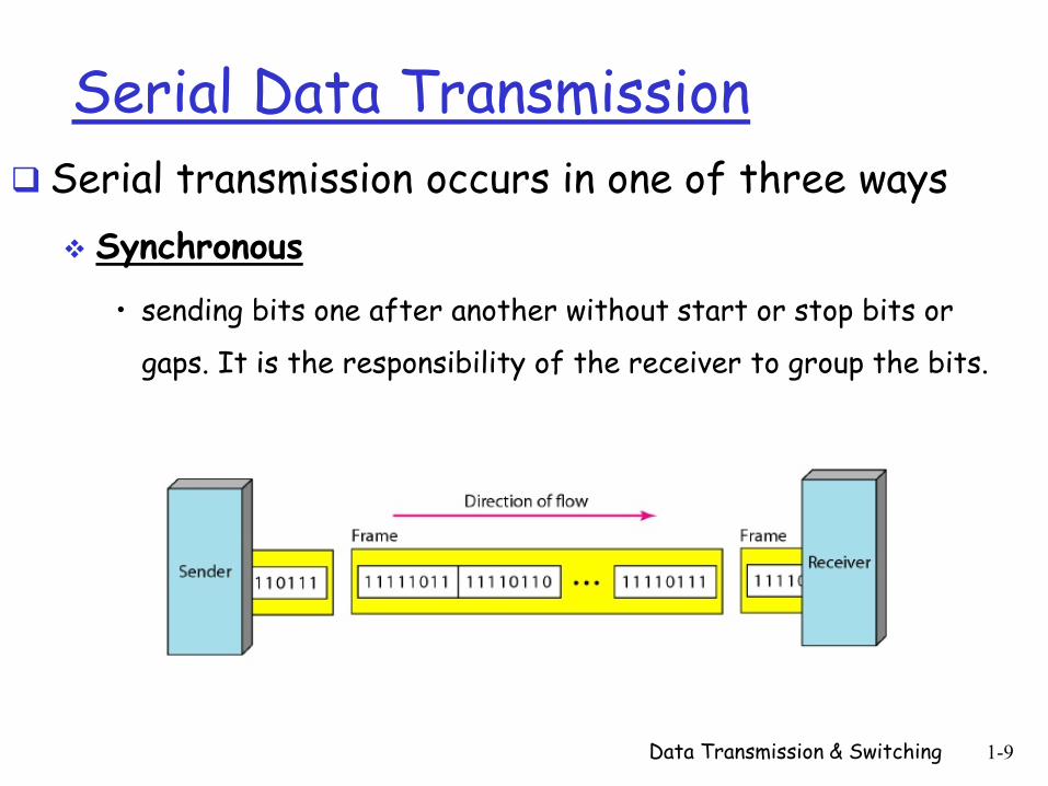
Serial Data Transmission
Serial transmission occurs in one of three ways
Synchronous
• sending bits one after another without start or stop bits or
gaps. It is the responsibility of the receiver to group the bits.
Data Transmission & Switching 1-9
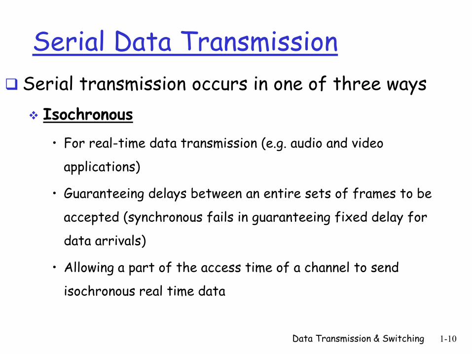
Serial Data Transmission
Serial transmission occurs in one of three ways
Isochronous
• For real-time data transmission (e.g. audio and video
applications)
• Guaranteeing delays between an entire sets of frames to be
accepted (synchronous fails in guaranteeing fixed delay for
data arrivals)
• Allowing a part of the access time of a channel to send
isochronous real time data
Data Transmission & Switching 1-10
Data Transmission & Switching 1-11
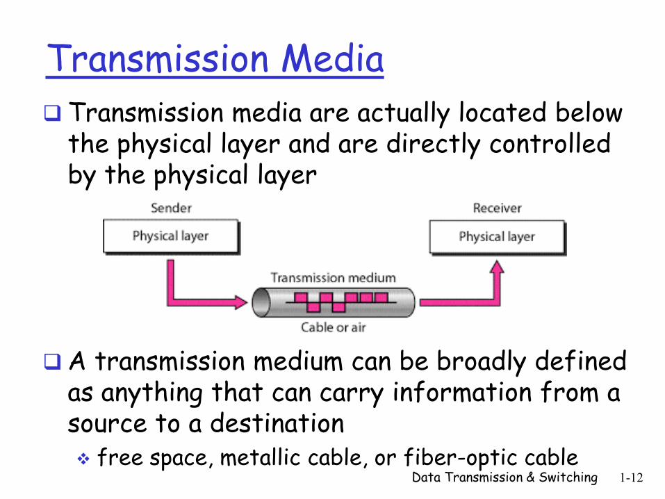
Transmission Media
Transmission media are actually located below the physical layer and are directly controlled by the physical layer
A transmission medium can be broadly defined as anything that can carry information from a source to a destination free space, metallic cable, or fiber-optic cable
Data Transmission & Switching 1-12
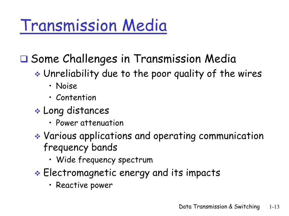
Transmission Media
Some Challenges in Transmission Media Unreliability due to the poor quality of the wires
• Noise
• Contention
Long distances • Power attenuation
Various applications and operating communication frequency bands
• Wide frequency spectrum
Electromagnetic energy and its impacts • Reactive power
Data Transmission & Switching 1-13
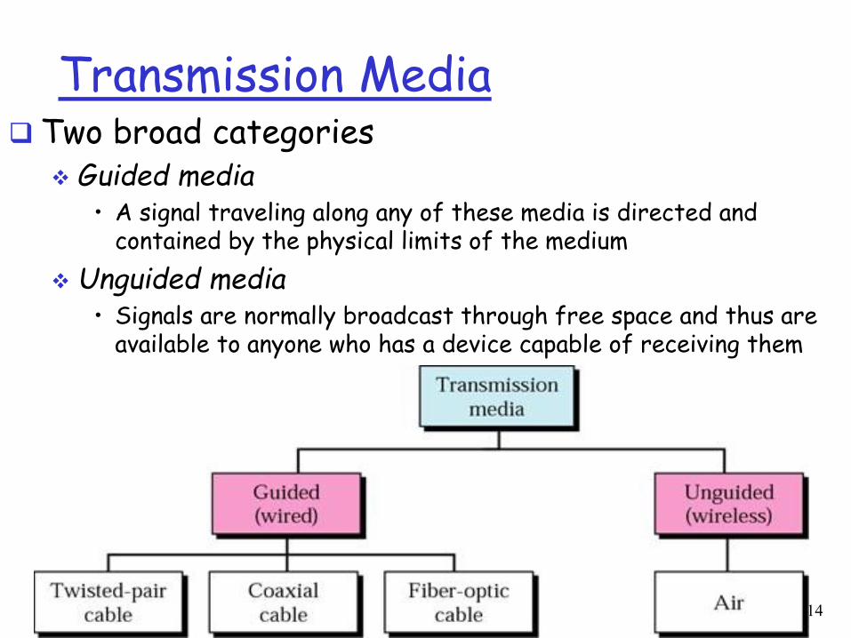
Transmission Media Two broad categories
Guided media • A signal traveling along any of these media is directed and
contained by the physical limits of the medium
Unguided media • Signals are normally broadcast through free space and thus are
available to anyone who has a device capable of receiving them
Data Transmission & Switching 1-14
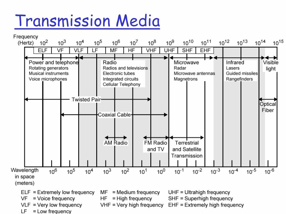
Transmission Media
Data Transmission & Switching 1-15
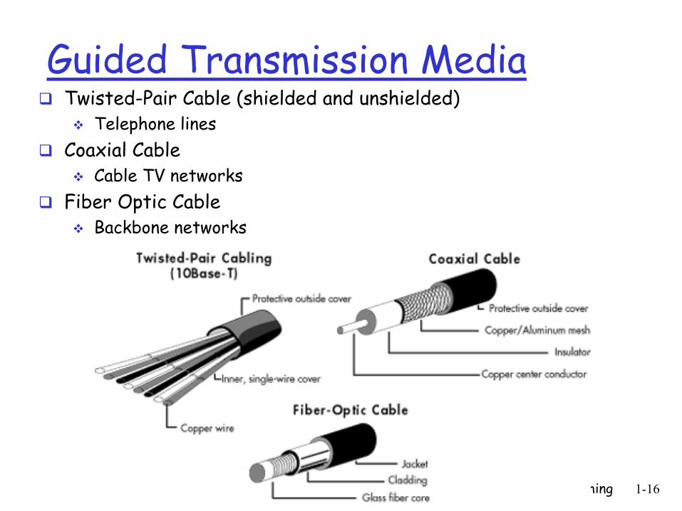
Guided Transmission Media Twisted-Pair Cable (shielded and unshielded)
Telephone lines
Coaxial Cable Cable TV networks
Fiber Optic Cable Backbone networks
Data Transmission & Switching 1-16
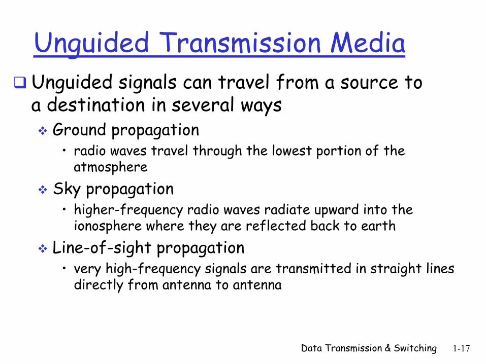
Unguided Transmission Media
Unguided signals can travel from a source to a destination in several ways Ground propagation
• radio waves travel through the lowest portion of the atmosphere
Sky propagation • higher-frequency radio waves radiate upward into the
ionosphere where they are reflected back to earth
Line-of-sight propagation • very high-frequency signals are transmitted in straight lines
directly from antenna to antenna
Data Transmission & Switching 1-17
Data Switching
A network is a set of connected devices
how to connect them to make one-to-one communication possible ? point-to-point connection between each pair of
devices
between a central device and every other device
impractical and wasteful when applied to very large networks !!!
A practical solution is network switching
Data Transmission & Switching 1-18
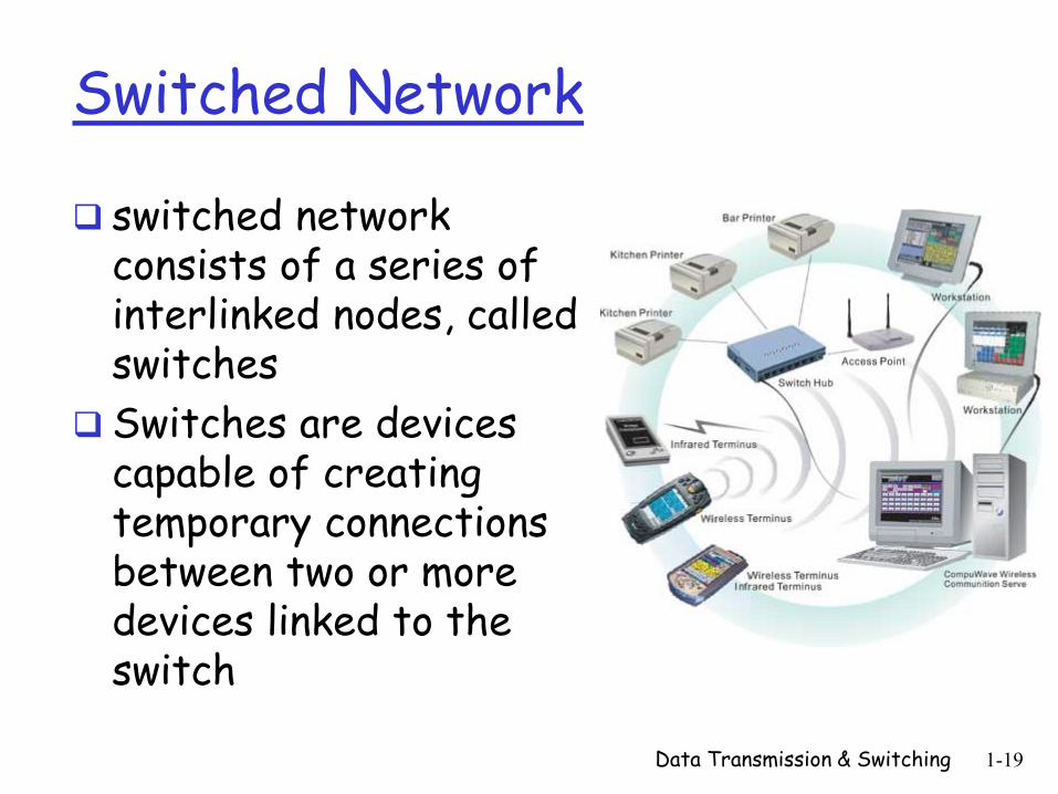
Switched Network
switched network consists of a series of interlinked nodes, called switches
Switches are devices capable of creating temporary connections between two or more devices linked to the switch
Data Transmission & Switching 1-19
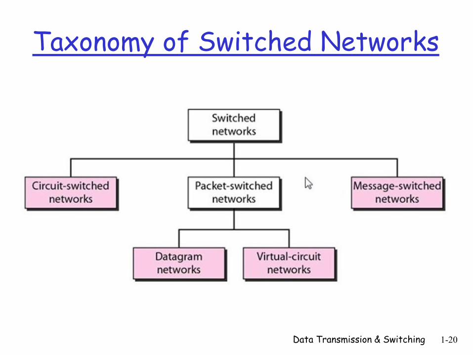
Taxonomy of Switched Networks
Data Transmission & Switching 1-20
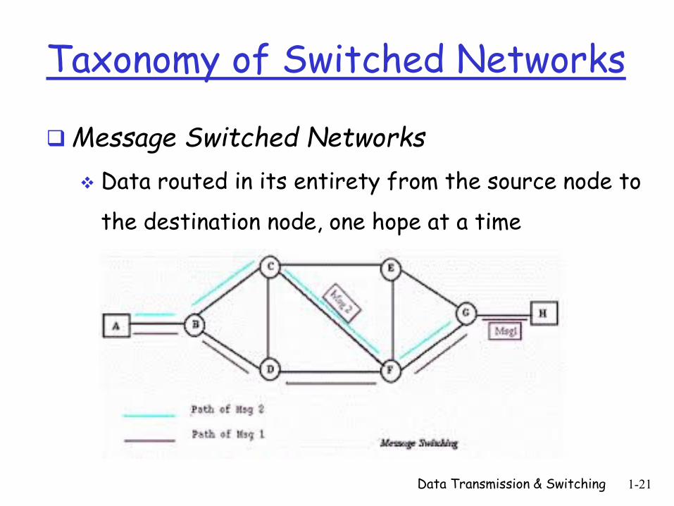
Taxonomy of Switched Networks
Message Switched Networks
Data routed in its entirety from the source node to
the destination node, one hope at a time
Data Transmission & Switching 1-21
Taxonomy of Switched Networks
Message Switched Networks
In message switching, each switch stores the
whole message and forwards it to the next
switch
• No packetization
• No resource allocation
It is still used in some applications like
electronic mail (e-mail)
Data Transmission & Switching 1-22
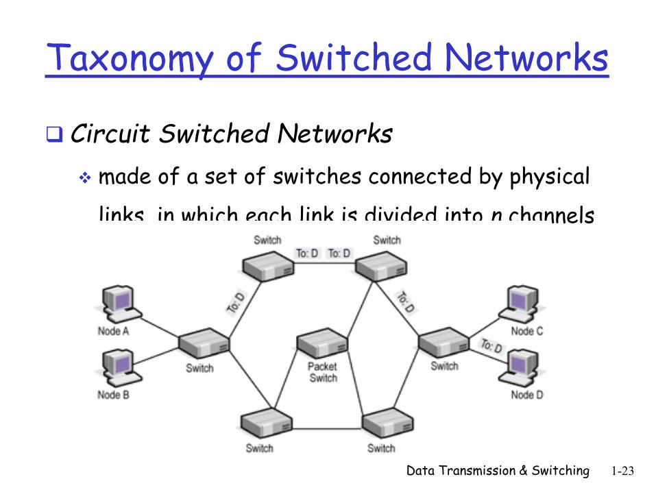
Taxonomy of Switched Networks
Circuit Switched Networks
made of a set of switches connected by physical
links, in which each link is divided into n channels
Data Transmission & Switching 1-23
Taxonomy of Switched Networks
Circuit Switched Networks
A connection between two stations is a dedicated
path made of one or more links
Each connection uses only one dedicated channel on
each link
Each link is normally divided into n channels by using
multiplexing techniques, such as FDM or TDM
(making shared medium)
Data Transmission & Switching 1-24
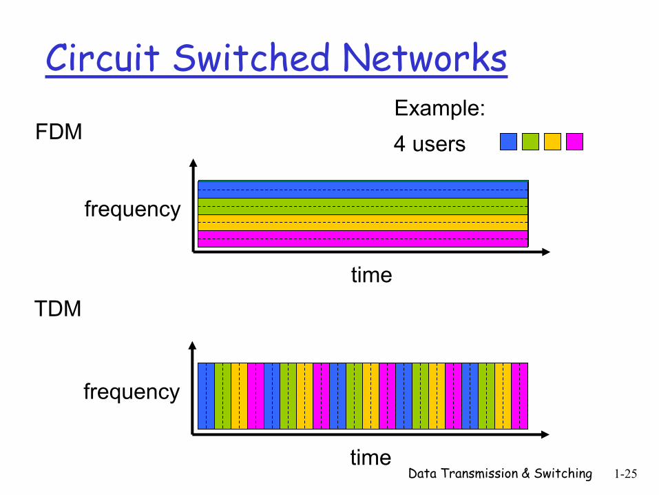
Circuit Switched Networks
Data Transmission & Switching 1-25
FDM
frequency
time
TDM
frequency
time
4 users
Example:
Taxonomy of Switched Networks
Circuit Switched Networks Circuit switching takes place at the physical layer
Before starting communication, the stations must make a reservation for the resources to be used during the communication (resource reservation)
The data are a continuous flow sent by the source station and received by the destination station (continuous data flow)
There is no addressing involved during data transfer (no addressing)
Data Transmission & Switching 1-26
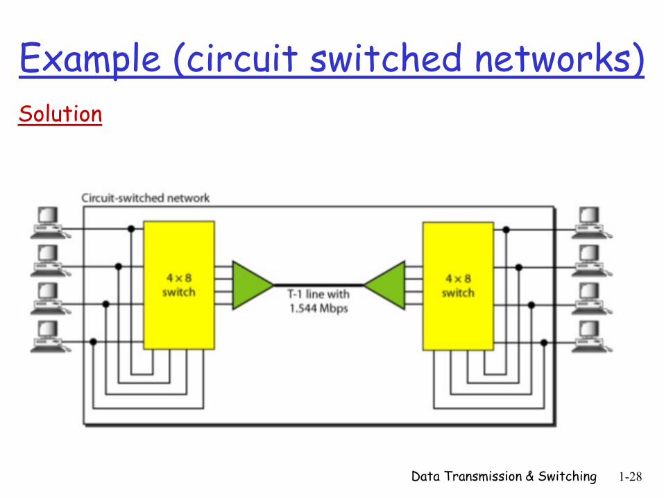
Example (circuit switched networks) Design and sketch a circuit-switched network that connects computers in two remote offices of a private company. The offices are connected using a T-1 line leased from a communication service provider.
There are two 4 X 8 (4 inputs and 8 outputs) switches in this network.
For each switch, four output ports are folded into the input ports to allow communication between computers in the same office.
Four other output ports allow communication between the two offices.
Data Transmission & Switching 1-27
Example (circuit switched networks)
Data Transmission & Switching 1-28
Solution
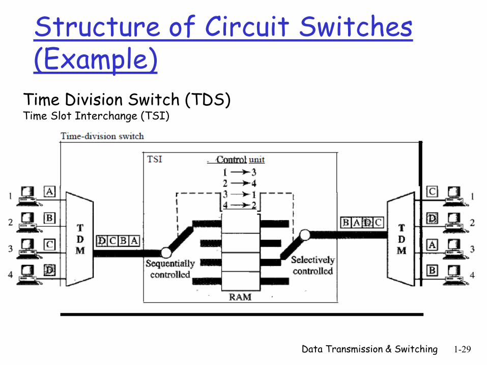
Structure of Circuit Switches (Example)
Data Transmission & Switching 1-29
Time Division Switch (TDS) Time Slot Interchange (TSI)
Circuit Switched Networks
Operation Phases
Setup Phase
• A dedicated circuit needs to be established
Data Transfer Phase
• After the establishment of the dedicated circuit, the two
parties can transfer data
Teardown Phase
• When one of the parties needs to disconnect, a signal is
sent to each switch to release the resources. Data Transmission & Switching 1-30
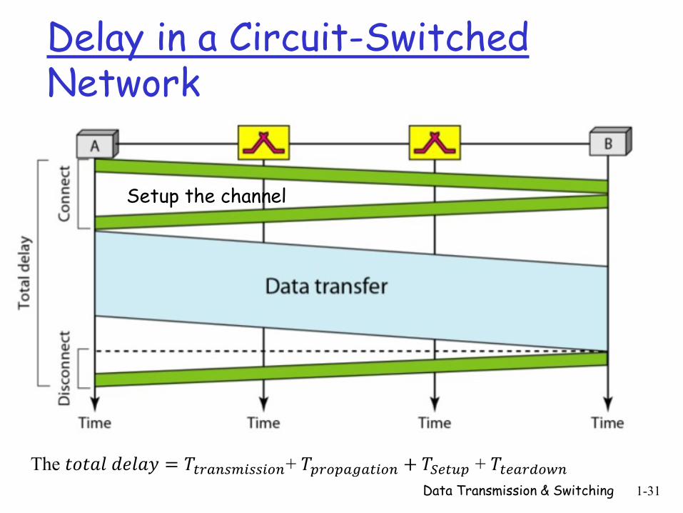
Delay in a Circuit-Switched Network
Data Transmission & Switching 1-31
Setup the channel
The 𝑡𝑜𝑡𝑎𝑙 𝑑𝑒𝑙𝑎𝑦 = 𝑇𝑡𝑟𝑎𝑛𝑠𝑚𝑖𝑠𝑠𝑖𝑜𝑛+ 𝑇𝑝𝑟𝑜𝑝𝑎𝑔𝑎𝑡𝑖𝑜𝑛 + 𝑇𝑆𝑒𝑡𝑢𝑝 + 𝑇𝑡𝑒𝑎𝑟𝑑𝑜𝑤𝑛
Taxonomy of Switched Networks
Packet Switched Networks: Datagram Networks
The data message is divided into packets of fixed or
variable size
The size of the packet is determined by the network
and the governing protocol
There is no resource pre-allocation for a packet
No reserved bandwidth on the links
No scheduled processing time for each packet
Data Transmission & Switching 1-32
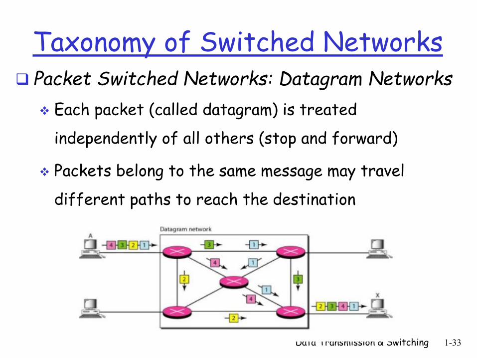
Taxonomy of Switched Networks Packet Switched Networks: Datagram Networks
Each packet (called datagram) is treated
independently of all others (stop and forward)
Packets belong to the same message may travel
different paths to reach the destination
Data Transmission & Switching 1-33
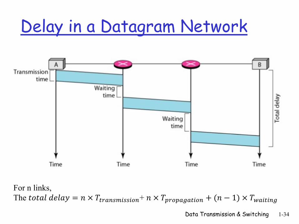
Delay in a Datagram Network
Data Transmission & Switching 1-34
For n links,
The 𝑡𝑜𝑡𝑎𝑙 𝑑𝑒𝑙𝑎𝑦 = 𝑛 × 𝑇𝑡𝑟𝑎𝑛𝑠𝑚𝑖𝑠𝑠𝑖𝑜𝑛+ 𝑛 × 𝑇𝑝𝑟𝑜𝑝𝑎𝑔𝑎𝑡𝑖𝑜𝑛 + (𝑛 − 1) × 𝑇𝑤𝑎𝑖𝑡𝑖𝑛𝑔
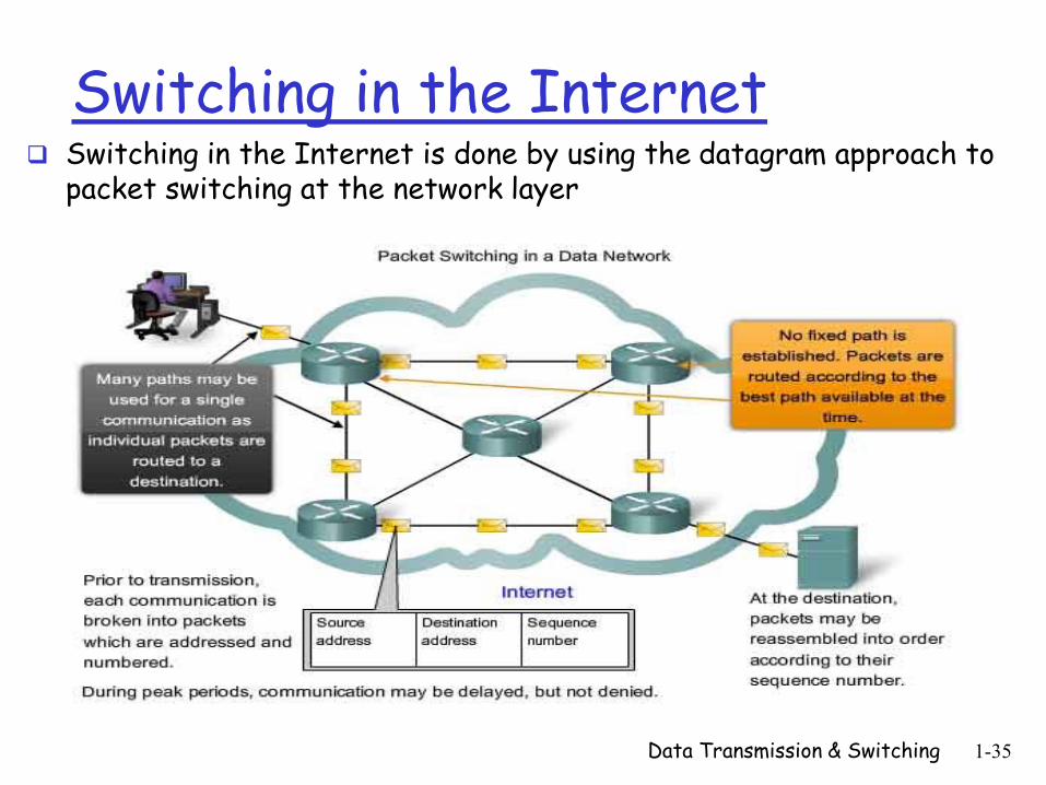
Switching in the Internet Switching in the Internet is done by using the datagram approach to
packet switching at the network layer
Data Transmission & Switching 1-35
Taxonomy of Switched Networks Packet Switched Networks: Virtual Circuit
Switched Networks A virtual-circuit network is a cross between a circuit-
switched network and a datagram network
There are setup and teardown phases
Resources can be allocated during the setup phase
Data are packetized and each packet carries an address in the header (common with datagram)
All packets follow the same path established during the connection (common with circuit switching)
Normally implemented in the data link layer (shared medium)
• Circuit-switched network is implemented in the physical layer
• Datagram network in the network layer 1-36
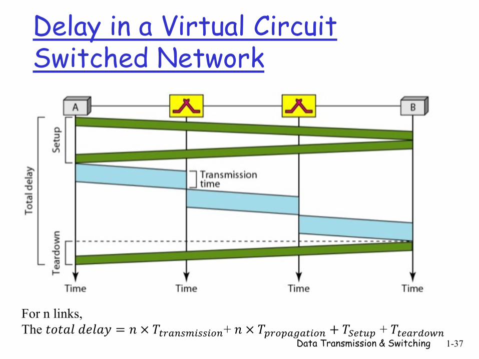
Delay in a Virtual Circuit Switched Network
Data Transmission & Switching 1-37
For n links,
The 𝑡𝑜𝑡𝑎𝑙 𝑑𝑒𝑙𝑎𝑦 = 𝑛 × 𝑇𝑡𝑟𝑎𝑛𝑠𝑚𝑖𝑠𝑠𝑖𝑜𝑛+ 𝑛 × 𝑇𝑝𝑟𝑜𝑝𝑎𝑔𝑎𝑡𝑖𝑜𝑛 + 𝑇𝑆𝑒𝑡𝑢𝑝 + 𝑇𝑡𝑒𝑎𝑟𝑑𝑜𝑤𝑛
Addressing in Virtual Circuit Switched Networks
Global Addressing
A source or a destination needs to have a global
address (i.e. an address that can be unique)
Local Addressing
Virtual-Circuit Identifier (VCI)
• A small number that has only switch scope
• It is used by a frame between two switches
• When a frame arrives at a switch, it has a VCI; when
it leaves, it has a different VCI Data Transmission & Switching 1-38
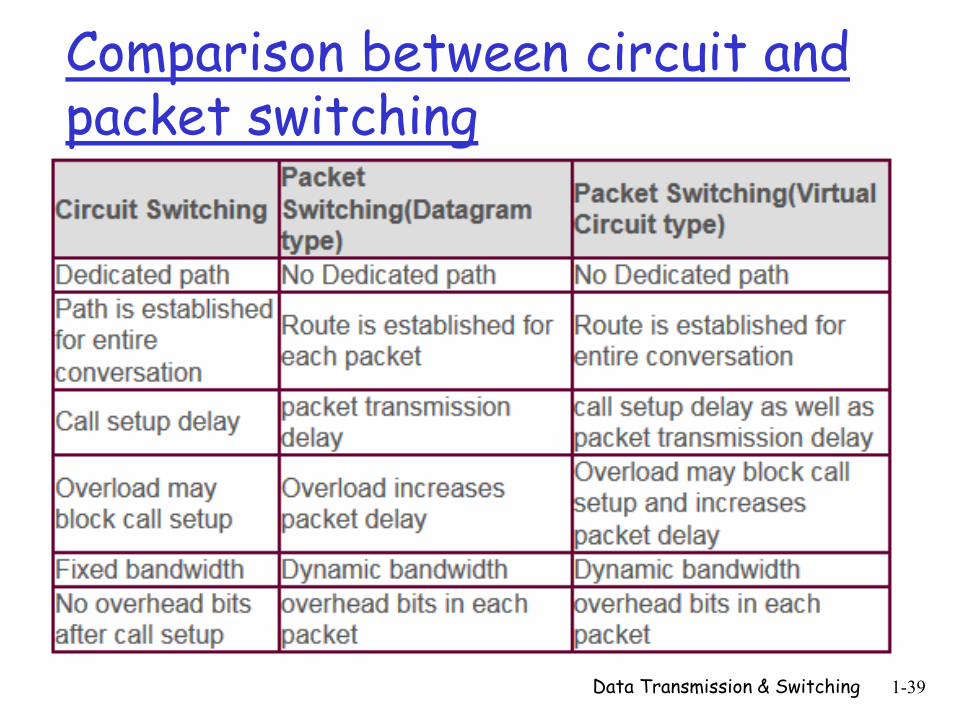
Comparison between circuit and packet switching
Data Transmission & Switching 1-39
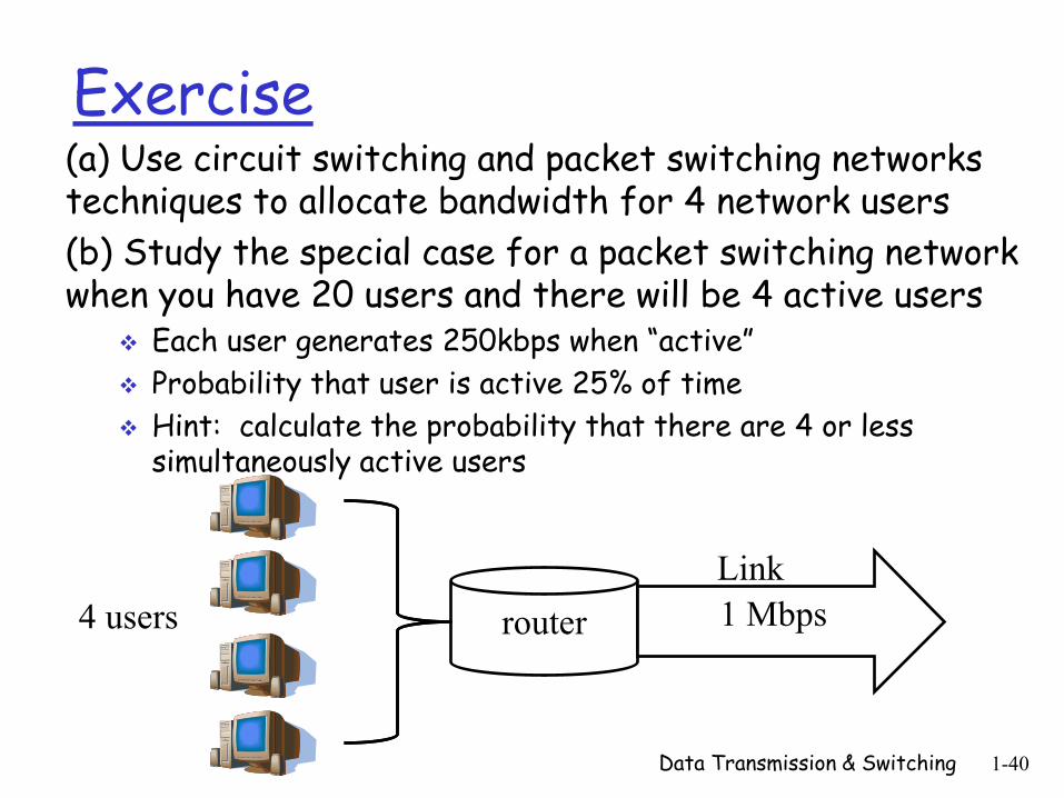
Exercise (a) Use circuit switching and packet switching networks techniques to allocate bandwidth for 4 network users
(b) Study the special case for a packet switching network when you have 20 users and there will be 4 active users
Each user generates 250kbps when “active”
Probability that user is active 25% of time
Hint: calculate the probability that there are 4 or less simultaneously active users
Data Transmission & Switching 1-40
router 1 Mbps 4 users
Link
Lecture-related Questions
Why does a circuit-switched network need end-to-end
addressing during the setup and teardown phases? Why
are no addresses needed during the data transfer phase
for this type of network?
What is the role of the address field in a packet traveling
through a datagram network?
Data Transmission & Switching 1-41
Data Transmission & Switching 1-42
Lecture Summary Covered material
Introduction to Data Transmission Modes Parallel and Serial Transmission
Transmission Media Guided and unguided media
Data Switching Techniques Circuit Switching
Packet Switching
Material to be covered next lecture Introduction to the Data Link Layer
Error Detection and Correction Flow and Error Control
![DATA COMMUNICATION AND NETWORKS IMPORTANT … · [Type text] Page 1 DATA COMMUNICATION AND NETWORKS IMPORTANT QUESTIONS WITH ANSWERS 1. Explain the types of transmission modes . Communication](https://img.pdfslide.us/doc/110x75/5e53d289b3249465d365508f/data-communication-and-networks-important-type-text-page-1-data-communication.jpg)