Embed Size (px)
Citation preview

Lecture 4.Applications

Summary
Tools such as HyTech, CheckMate, Uppaal, Kronos have been used in many contextstypically to verify safety of a control design or to get tight bounds on parameters (e.g. steam boiler, audio control)
This lecture shows where hybrid systems theory can fit in some application domains

Applications Outline
! Embedded Control Systems" Autonomous Mobile Robots" Biological Systems

Embedded Controller Development ProcessFor Automobile Transmissions
test on engine/vehicle
feature specification
code
production
Former Practice• describe control logic using
relay-ladder diagrams
• write assembly code for the control microprocessor
• drive the car around the test track
• fix bugs
• redesign
• hope for the best

Automotive Embedded Controller Design: State of the Practice
test on engine/vehicle
feature specification
code
production
executable spec.
code generation
simulation
hardware in the loop
executable spec.
Computer-Aided Control System Design

Executable Specifications Using MATLAB/Simulink/Stateflow

Transmission Control Logic

Opportunity to Apply Formal Verification Techniques
test on engine/vehicle
feature specification
code
production
executable spec.
code generation
simulation
hardware in the loop
executable spec.
Computer-Aided Control System Design
model checking
Objective:Verify feature behavior for the entire range of operating conditions.

Automotive Engine Control in Cut-off Mode
Application of CheckMate due to Krogh et al
Control law: Decide when to inject air/fuel for torque to minimize acceleration peaks during the cut-off operation.
Problem: Verify the event-driven implementation of a control law designed in continuous time.

Automotive Powertrain Model
Model from Magneti Marelli Engine Control Division
• Four-stroke, four cylinder engine
• Continuous-time powertrain model
• Hybrid model for cylinder cycles

x2
x1 v x2
x1
torque
start
simula
simula
C*x <= d
reach_zero
C*x <= d
reach_180
h000
h001
h010
h011
h100
h101
h110
h111
q
predictor
NOT
not2
NOT
not1
C*x <= d
h111
C*x <= d
h110
C*x <= d
h101
C*x <= d
h100
C*x <= d
h011
C*x <= d
h010
C*x <= d
h001
C*x <= d
h000
C*x <= d
finish_line
drivel ine
XORangle_trigger
angle (degrees)
q
angle
NOTNOT
u
M4
Mux M3
u
M2
MuxM1m
Demux
CheckMate Model
power traindynamics
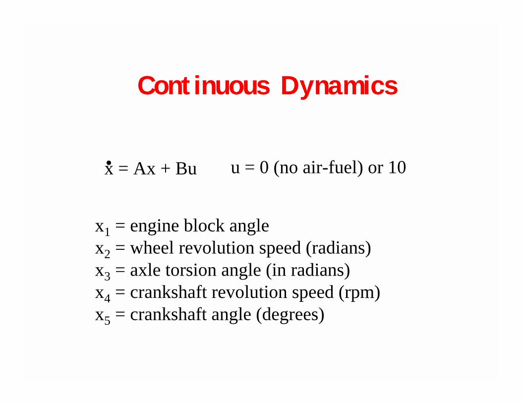
Continuous Dynamics
x = Ax + Bu u = 0 (no air-fuel) or 10
x1 = engine block anglex2 = wheel revolution speed (radians)x3 = axle torsion angle (in radians)x4 = crankshaft revolution speed (rpm)x5 = crankshaft angle (degrees)

Controller Specification
Remain within acceleration
limits while tracking a sliding mode.
• Sliding mode control law derived in continuous time• Hybrid implementation due to discrete torque decisions

Cylinder Cycle
Phase_change
Phase_change
Phase_changePhase_change
Compression
Exhaust Intake
Combustion
Control decision to apply torque on the power stroke must be madebefore the intake stroke ⇒ three step lookahead.

x2
x1 v x2
x1
torque
start
simula
simula
C*x <= d
reach_zero
C*x <= d
reach_180
h000
h001
h010
h011
h100
h101
h110
h111
q
predictor
NOT
not2
NOT
not1
C*x <= d
h111
C*x <= d
h110
C*x <= d
h101
C*x <= d
h100
C*x <= d
h011
C*x <= d
h010
C*x <= d
h001
C*x <= d
h000
C*x <= d
finish_line
driveline
XORangle_trigger
angle (degrees)
q
angle
NOTNOT
u
M4
Mux M3
u
M2
MuxM1m
Demux
Crankshaft Angle Rate Logic
Cylinder state transitions occur every 180o. Crankshaft angle switches between 0o and 180o, angle rate switches between +rate and -rate.

Predictive Control Logic
The discrete state indicates the torquedecisions for the current and next twopower strokes (i.e., for three of thefour cylinders).
Transitions from each state dependon whether predicted state for thenext power stroke is closer to thesliding mode with or without torque.
The 9th state (not shown) is the “end simulation” state--reachable from any of the other 8 states.

Flowpipe for One Discrete Sequence

Applications Outline
# Embedded Control Systems! Autonomous Mobile Robots" Biological Systems

Programming Interacting Autonomous Robots
Many modesIndividual modes are well understood, but not their interaction.
Software designModes designed bottom-upProtocols top-down
Modular design to ensure reusability
Tasks: Formation control, cooperative control

Software Design MethodologyCHARON Code
(High level language)
Java Code
CHARON to Java TranslatorCHARON to Java Translator
Control Code GeneratorControl Code Generator
Java Libraries
Human InterfaceHuman Interface
Simulator Code GeneratorSimulator Code Generator
Drivers

Vision-Based Control: Mode Switching

Motion Controller
Reactive Vision Based Controllers
Frame Grabber Actuators
AvoidObstacle
CollisionRecovery
EdgeDetector
CollisionDetector
Color BlobFinder
Robot PositionEstimator
TargetDetector
Range Mapper
Wall-Following
Control
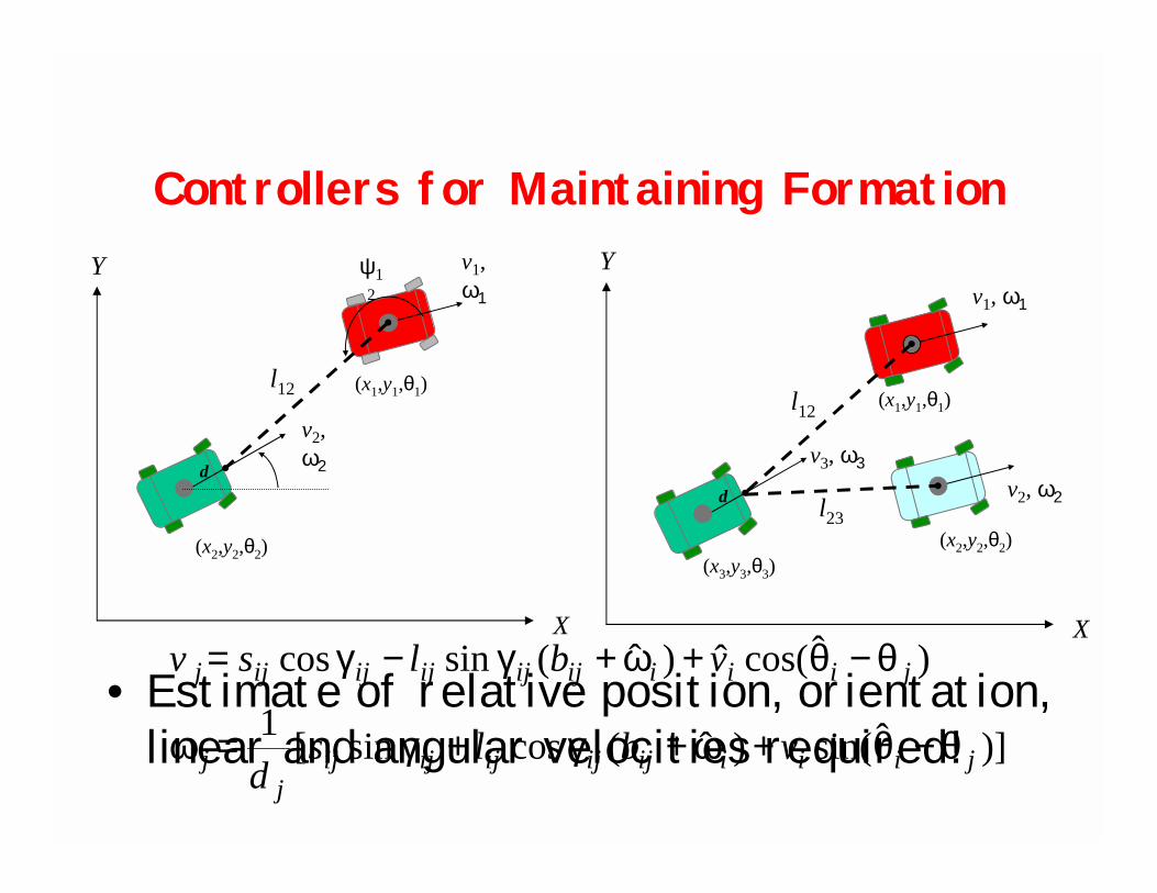
Controllers for Maintaining Formation
X
Y
d
(x2,y2,θ2)
(x1,y1,θ1)l12
v1, ω1
ψ12
v2, ω2
X
Y
d
(x2,y2,θ2)
(x1,y1,θ1)l12
v1, ω1
(x3,y3,θ3)
l23v2, ω2
v3, ω3
• Estimate of relative position, orientation, linear and angular velocities required! )]ˆsin()ˆ(cossin[1
)ˆcos(ˆ)ˆ(sincos
jiiiijijijijijj
j
jiiiijijijijijj
vblsd
vblsv
θ−θ+ω+γ+γ=ω
θ−θ+ω+γ−γ=

Multirobot Coordination
R1
R2
R3
R1
R2R3

Rules for Mode Switching
R2
R1
R3
l12
l13
l23
l12l23
r1 r2
r1
r2
l13
AutonomousNavigation
l-ψψψψ13
l-ψψψψ23
l12 l- l
l13 = l23
l13 = l23 + l12
l13 = l23 - l12
l12 =l13 + l23
R
r2
r1
Sensor constraints

Leader Follower and Obstacle Avoidance
Leader is teleoperated Leader is autonomous
Obs
R1
R2 l12
lO2R2 R1
(l12,,ψ12 )

Mode Switching and Maintain Formation

Applications Outline
# Embedded Control Systems# Autonomous Mobile Robots! Biological Systems

Cellular Networks
"Networks of interacting biomolecules carry out many essential functions in living cells (gene regulation, protein production)
"Both positive and negative feedback loops"Design principles poorly understood "Large amounts of data is becoming available"Beyond Human Genome: Behavioral models of
cellular networks"Modeling becoming increasingly relevant as an
aid to narrow the space of experiments

Regulatory Networks
cell-to-cellsignaling
START STOPgene
transcriptiontranslation
regulation
nascentprotein
chemicalreaction
+
-
negative
positive
gene expression

Hybrid Modeling of Biological Systems
START STOPluxR gene
transcriptiontranslation
regulation
proteinLuxR
chemicalreaction
-+
negative
positive
Ai
Ai
CRP
Traditionally, biological systems are modeled using smooth functions.
Xmκ
Xmν
X
),,X( XmXm νκΦ
10.5
2swX1
swX
transporttransformdecaysynthesisdt
]x[d ±±−=
luxRkHluxR
)b)),,AiLuxR(1(
),,CRP([Tdt
)luxR(d
GRNA
AiLuxRAiLuxR
CRPCRPc
−−
+−−
=
−− νκΦ
νκΦ
LuxRkCorLuxRAir
HLuxRluxRT
dt)LuxR(d
Gdb
spl
Ai/LuxRAi/LuxR−+−
−−=

Hybrid ModelingAt low concentrations, a continuous approximation model might not be appropriate. Instead, a stochastic model should be used.
stochastic modellow conc
continuous modelhigh conc
In some cases, the biological description of a system is itself hybrid.
Essentiallyhybrid systemDiscrete jump
(mRNA)
Nonlinear dynamics(proteins involved in chemical reactions)
Linear dynamics(proteins not involvedin chemical reactions)
moderegulatoryprotein/complex

Luminescence / Quorum Sensingin Vibrio Fischeri

Luminescence Regulation
CRP
luxICDABEGluxR
Ai
LuxA
LuxB
luciferase
LuxI
Substrate
LuxR
lux box
CRP binding siteLuxR Ai
OL OR
-
+-
+ cAMP

Reachability
)Co(x 8
)Ai(x7
)L I(
switching surface
lum dynamics
nonlum dynamics
sw88 xx =
10bAxx +=&
sw88 xx ≥
lum
00bAxx +=&
sw88 xx ≤
non-lum
sw88 xx =
Under what conditionscan the bacterium switch on the light?
sw8x
0ibAxx +=&
=
8
7
4
xxx
x
+=
00
)bc(TTHb
iclRNA
0i
1c,0c 10 ==

Simulation Results
external Ai(input)
concentrationsfor various
entities
luminesence(output)
switchhistory
switchhistory

Summary
$ Hybrid systems are necessary to model some biological regulatory networks.
$ The simulation results of the luminescence control in Vibriofischeri are in accordance with phenomena observed in experiments.
$ Modeling concepts such as hierarchy, concurrency, reuse, are relevant for modular specifications
$ Exploiting the structure of real biological systems will be essential to meet the challenge posed by the enormous complexity of biological regulatory networks.

Conclusions
" A rich variety of domains match hybrid systems paradigm
" Traditional benefits: safety verification, design of hybrid controllers
" Formal models can be beneficial in more ways: modeling, understanding, programming, simulation
" Emerging potential for integration with software engineering design tools