Embed Size (px)
Citation preview

Lecture #3Torsion of opened cross sections.Loads on frame due to fuselage bending

SHEAR STRESSES RELATED QUESTIONS
2
- shear flows due to the shear force, with no torsion;
- shear center;
- torsion of closed contour;
- torsion of opened contour, restrained torsion and deplanation;
- shear flows in the closed contour under combined action of bending and torsion;
- twisting angles;
- shear flows in multiple-closed contours.

SHEAR CENTER AND TORSION - ILLUSTRATION
3

TORSION IN MECHANICS OF MATERIALS
4
The measure of resistance to torsion is a polar moment of inertia I.
Relative twist angle
Maximal shear stress
zM
G I
max maxzM
I
4
32d
I
3I h b

TORSION IN THIN-WALLED CROSS SECTIONS
5
The polar moment of inertia I is calculated as a sum
for rectangular portions of thin-walled cross section.
Relative twist angle Maximal shear stress
zM
G I
313 i i
i
I b
max maxzM
I
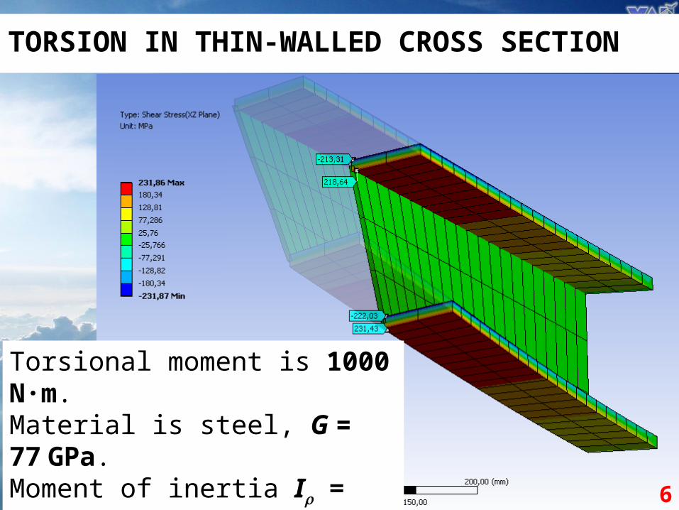
TORSION IN THIN-WALLED CROSS SECTION
6
Torsional moment is 1000 N·m.Material is steel, G = 77 GPa.Moment of inertia I = 4.14 cm4. Shear stress max = 241.3 MPa.

CALCULATION OF DEPLANATIONS (WARPING)
7
Since the hypothesis of planar cross section is not valid, the beam theory is not applicable.
Thus, specific theory developed by Vlasov is used.
Vlasov’s theory is based on two main hypotheses:
1) The cross section keeps its shape and rotates as a whole around the shear center.
2) There are no shear strains and stresses at the middle plane (tz = 0).

where – angle of rotation of cross section along z axis; – lever from the shear center to the direction of t axis at the given point.
CALCULATION OF DEPLANATIONS
8
where w – displacement along z axis (deplanation);u – displacement along t axis.
0tz
w ut z
w dt
t dz

CALCULATION OF DEPLANATIONS
9
where w0 –displacement at the start point.
If start point is set on the axis of symmetry, we get
where t – sectorial coordinate (doubled area covered by rotation of radius-vector):
t
t t dt
0t
w t w t dt
w t t

CALCULATION OF DEPLANATIONS
10
Analytical values:Max is 0.67 mmAt the corner is 0.51 mm

NORMAL STRESSES AT RESCTRICTED TORSION
11
Normal stresses could be found using the formula
where I – sectorial moment of inertia:
B – bimoment (kind of scalar force factor):
Bt t
I
2
t
I t dt 2
2
dB E I
d z

NORMAL STRESSES AT RESCTRICTED TORSION
12
The distribution of normal stresses for real structure is usually quite complex, so it is usually wise to use FEA.

COMPARISON OF OPENED AND CLOSED CONTOURS
13
Let’s take a thin-walled circle with radius 1 m and thickness of 2 mm.For the closed contour we get 628,300 cm4, while for opened – only 1.67, which is 375 thousands times smaller.
For a tube of 25 mm diameter and thickness of 2 mm we get:For the closed contour we get the polar moment of inertia of 1.227 cm4, while for opened – 0.021 cm4, which is 57 times smaller.If we would increase the diameter, the difference will be increased dramatically.

LOADING OF FUSELAGE FRAME DUE TO BENDING OF FUSELAGE
If the cross section is subjected to bending with moment Mx , the specific normal force is equal to
Here is effective thickness ofskin (includes stringers);Ix is moment of inertia for cross
section:
sinz xz
x
dN MR
dt I
3xI R
14
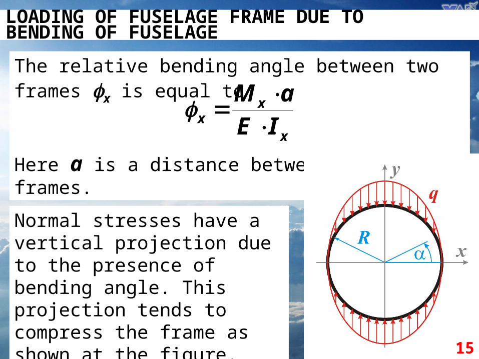
LOADING OF FUSELAGE FRAME DUE TO BENDING OF FUSELAGE
The relative bending angle between two frames x is
equal to
Here a is a distance betweenframes.
xx
x
M aE I
15
Normal stresses have a vertical projection due to the presence of bending angle. This projection tends to compress the frame as shown at the figure.

LOADING OF FUSELAGE FRAME DUE TO BENDING OF FUSELAGE
The distributed load on the frame could found as
16
By making few transformations, we get
2
2 sin2
z x x
x
dN M a Rq
dt I E
0
2
0 2 5
sin ;
x
q q
M aq
R E

WHERE TO FIND MORE INFORMATION?
17
Megson. An Introduction to Aircraft Structural Analysis. 2010Chapter 17.2
… Internet is boundless …