Embed Size (px)
Citation preview

NPTEL – Chemical – Chemical Technology II
Joint initiative of IITs and IISc – Funded by MHRD Page 1 of 83
Lecture 3: Petroleum Refining Overview
In this lecture, we present a brief overview of the petroleum refining, a
prominent process technology in process engineering.
3.1 Crude oil
Crude oil is a multicomponent mixture consisting of more than 108
compounds. Petroleum refining refers to the separation as well as reactive
processes to yield various valuable products. Therefore, a key issue in the
petroleum refining is to deal with multicomponent feed streams and
multicomponent product streams. Usually, in chemical plants, we encounter
streams not possessing more than 10 components, which is not the case in
petroleum refining. Therefore, characterization of both crude, intermediate
product and final product streams is very important to understand the
processing operations effectively.
3.2 Overview of Refinery processes
Primary crude oil cuts in a typical refinery include gases, light/heavy
naphtha, kerosene, light gas oil, heavy gas oil and residue. From these
intermediate refinery product streams several final product streams such as
fuel gas, liquefied petroleum gas (LPG), gasoline, jet fuel, kerosene, auto
diesel, lubricants, bunker oil, asphalt and coke are obtained. The entire
refinery technology involves careful manipulation of various feed properties
using both chemical and physical changes.
Conceptually, a process refinery can be viewed upon as a combination of
both physical and chemical processes or unit operations and unit processes
respectively. Typically, the dominant physical process in a refinery is the
distillation process that enables the removal of lighter components from the
heavier components. Other chemical processes such as alkylation and
isomerisation are equally important in the refinery engineering as these
processes enable the reactive transformation of various functional groups to
desired functional groups in the product streams.
3.3 Feed and Product characterization
The characterization of petroleum process streams is approached from both
chemistry and physical properties perspective. The chemistry perspective
indicates to characterize the crude oil in terms of the functional groups such
as olefins, paraffins, naphthenes, aromatics and resins. The dominance of
one or more of the functional groups in various petroleum processing
streams is indicative of the desired product quality and characterization. For
instance, the lighter fractions of the refinery consist of only olefins and
paraffins. On the other hand, products such as petrol should have high
octane number which is a characteristic feature of olefinic and aromatic
functional groups present in the product stream.
NPTEL – Chemical – Chemical Technology II
Joint initiative of IITs and IISc – Funded by MHRD Page 2 of 83
The physical characterization of the crude oil in terms of viscosity, density,
boiling point curves is equally important. These properties are also
indicative of the quality of the product as well as the feed. Therefore, in
petroleum processing, obtaining any intermediate or a product stream with a
defined characterization of several properties indicates whether it is diesel
or petrol or any other product. This is the most important characteristic
feature of petroleum processing sector in contrary to the chemical process
sector.
The product characterization is illustrated now with an example. Aviation
gasoline is characterized using ASTM distillation. The specified
temperatures for vol% distilled at 1 atm. Are 158 oF maximum for 10 %
volume, 221 oF maximum for 50 % volume and 275
oF maximum for 90%
volume. This is indicative of the fact that any product obtained in the
refinery process and meets these ASTM distillation characteristics is
anticipated to represent Aviation gasoline product. However, other
important properties such as viscosity, density, aniline product, sulphur
density are as well measured to fit within a specified range and to conclude
that the produced stream is indeed aviation gasoline.
3.4 Important characterization properties
Numerous important feed and product characterization properties in refinery
engineering include
- API gravity
- Watson Characterization factor
- Viscosity
- Sulfur content
- True boiling point (TBP) curve
- Pour point
- Flash and fire point
- ASTM distillation curve
- Octane number
3.4.1 API gravity
API gravity of petroleum fractions is a measure of density of the stream.
Usually measured at 60 oF, the API gravity is expressed as
oAPI = 141.5/specific gravity – 131.5
where specific gravity is measured at 60 oF.
According to the above expression, 10 oAPI gravity indicates a specific
gravity of 1 (equivalent to water specific gravity). In other words, higher
values of API gravity indicate lower specific gravity and therefore lighter
NPTEL – Chemical – Chemical Technology II
Joint initiative of IITs and IISc – Funded by MHRD Page 3 of 83
crude oils or refinery products and vice-versa. As far as crude oil is
concerned, lighter API gravity value is desired as more amount of gas
fraction, naphtha and gas oils can be produced from the lighter crude oil
than with the heavier crude oil. Therefore, crude oil with high values of
API gravity are expensive to procure due to their quality.
3.4.2 Watson characterization factor
The Watson characterization factor is usually expressed as
K = (TB)1/3
/specific gravity
Where TB is the average boiling point in degrees R taken from five
temperatures corresponding to 10, 30, 50, 70 and 90 volume % vaporized.
Typically Watson characterization factor varies between 10.5 and 13 for
various crude streams. A highly paraffinic crude typically possesses a K
factor of 13. On the other hand, a highly naphthenic crude possesses a K
factor of 10.5. Therefore, Watson characterization factor can be used to
judge upon the quality of the crude oil in terms of the dominance of the
paraffinic or naphthenic components.
3.4.3 Sulfur content
Since crude oil is obtained from petroleum reservoirs, sulphur is present in
the crude oil. Usually, crude oil has both organic and inorganic sulphur in
which the inorganic sulphur dominates the composition. Typically, crude
oils with high sulphur content are termed as sour crude. On the other hand,
crude oils with low sulphur content are termed as sweet crude. Typically,
crude oil sulphur content consists of 0.5 – 5 wt % of sulphur. Crudes with
sulphur content lower than 0.5 wt % are termed as sweet crudes. It is
estimated that about 80 % of world crude oil reserves are sour.
The sulphur content in the crude oil is responsible for numerous
hydrotreating operations in the refinery process. Strict and tighter
legislations enforce the production of various consumer petroleum products
with low quantities of sulphur (in the range of ppm). Presently, India is
heading towards the generation of diesel with Euro III standards that
indicates that the maximum sulphur content is about 500 ppm in the
product. This indicates that large quantities of inorganic sulphur needs to be
removed from the fuel. Typically, inorganic sulphur from various
intermediate product streams is removed using hydrogen as hydrogen
sulphide.
A typical refinery consists of good number of hydrotreaters to achieve the
desired separation. The hydrotreaters in good number are required due to
the fact that the processing conditions for various refinery intermediate
process streams are significantly different and these streams cannot be
blended together as well due to their diverse properties which were achieved
NPTEL – Chemical – Chemical Technology II
Joint initiative of IITs and IISc – Funded by MHRD Page 4 of 83
using the crude distillation unit. More details with respect to the
hydrotreating units will be presented in the future lectures.
3.4.4 TBP/ASTM distillation curves
The most important characterization properties of the
crude/intermediate/product streams are the TBP/ASTM distillation curves.
Both these distillation curves are measured at 1 atm pressure. In both these
cases, the boiling points of various volume fractions are being measured.
However, the basic difference between TBP curve and ASTM distillation
curve is that while TBP curve is measured using batch distillation apparatus
consisting of no less than 100 trays and very high reflux ratio, the ASTM
distillation is measured in a single stage apparatus without any reflux.
Therefore, the ASTM does not indicate a good separation of various
components and indicates the operation of the laboratory setup far away
from the equilibrium.
3.4.5 Viscosity
Viscosity is a measure of the flow properties of the refinery stream.
Typically in the refining industry, viscosity is measured in terms of
centistokes (termed as cst) or saybolt seconds or redwood seconds. Usually,
the viscosity measurements are carried out at 100 oF and 210
oF. Viscosity
is a very important property for the heavy products obtained from the crude
oil. The viscosity acts as an important characterization property in the
blending units associated to heavy products such as bunker fuel. Typically,
viscosity of these products is specified to be within a specified range and
this is achieved by adjusting the viscosities of the streams entering the
blending unit.
3.4.6 Flash and fire point
Flash and fire point are important properties that are relevant to the safety
and transmission of refinery products. Flash point is the temperature above
which the product flashes forming a mixture capable of inducing ignition
with air. Fire point is the temperature well above the flash point where the
product could catch fire. These two important properties are always taken
care in the day to day operation of a refinery.
3.4.7 Pour point
When a petroleum product is cooled, first a cloudy appearance of the
product occurs at a certain temperature. This temperature is termed as the
cloud point. Upon further cooling, the product will ceases to flow at a
temperature. This temperature is termed as the pour point. Both pour and
cloud points are important properties of the product streams as far as heavier
products are concerned. For heavier products, they are specified in a
NPTEL – Chemical – Chemical Technology II
Joint initiative of IITs and IISc – Funded by MHRD Page 5 of 83
desired range and this is achieved by blending appropriate amounts of
lighter intermediate products.
3.4.8 Octane number
Though irrelevant to the crude oil stream, the octane number is an important
property for many intermediate streams that undergo blending later on to
produce automotive gasoline, diesel etc. Typically gasoline tends to knock
the engines. The knocking tendency of the gasoline is defined in terms of
the maximum compression ratio of the engine at which the knock occurs.
Therefore, high quality gasoline will tend to knock at higher compression
ratios and vice versa. However, for comparative purpose, still one needs to
have a pure component whose compression ratio is known for knocking.
Iso-octane is eventually considered as the barometer for octane number
comparison. While iso-octane was given an octane number of 100, n-
heptane is given a scale of 0. Therefore, the octane number of a fuel is
equivalent to a mixture of a iso-octane and n-heptane that provides the same
compression ratio in a fuel engine. Thus an octane number of 80 indicates
that the fuel is equivalent to the performance characteristics in a fuel engine
fed with 80 vol % of isooctane and 20 % of n-heptane.
Octane numbers are very relevant in the reforming, isomerisation and
alkylation processes of the refining industry. These processes enable the
successful reactive transformations to yield long side chain paraffins and
aromatics that possess higher octane numbers than the feed constituents
which do not consist of higher quantities of constituents possessing straight
chain paraffins and non-aromatics (naphthenes).
3.5 Crude chemistry
Fundamentally, crude oil consists of 84 – 87 wt % carbon, 11 – 14 %
hydrogen, 0 – 3 wt % sulphur, 0 – 2 wt % oxygen, 0 – 0.6 wt % nitrogen
and metals ranging from 0 – 100 ppm. Understanding thoroughly the
fundamentals of crude chemistry is very important in various refining
processes. The existence of compounds with various functional groups and
their dominance or reduction in various refinery products is what is
essentially targeted in various chemical and physical processes in the
refinery.
Based on chemical analysis and existence of various functional groups,
refinery crude can be broadly categorized into about 9 categories
summarized as
NPTEL – Chemical – Chemical Technology II
Joint initiative of IITs and IISc – Funded by MHRD Page 6 of 83
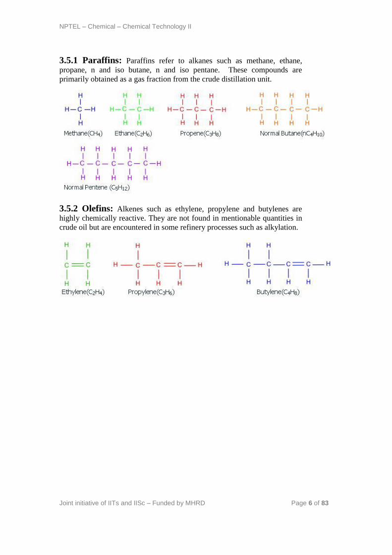
3.5.1 Paraffins: Paraffins refer to alkanes such as methane, ethane,
propane, n and iso butane, n and iso pentane. These compounds are
primarily obtained as a gas fraction from the crude distillation unit.
3.5.2 Olefins: Alkenes such as ethylene, propylene and butylenes are
highly chemically reactive. They are not found in mentionable quantities in
crude oil but are encountered in some refinery processes such as alkylation.
NPTEL – Chemical – Chemical Technology II
Joint initiative of IITs and IISc – Funded by MHRD Page 7 of 83
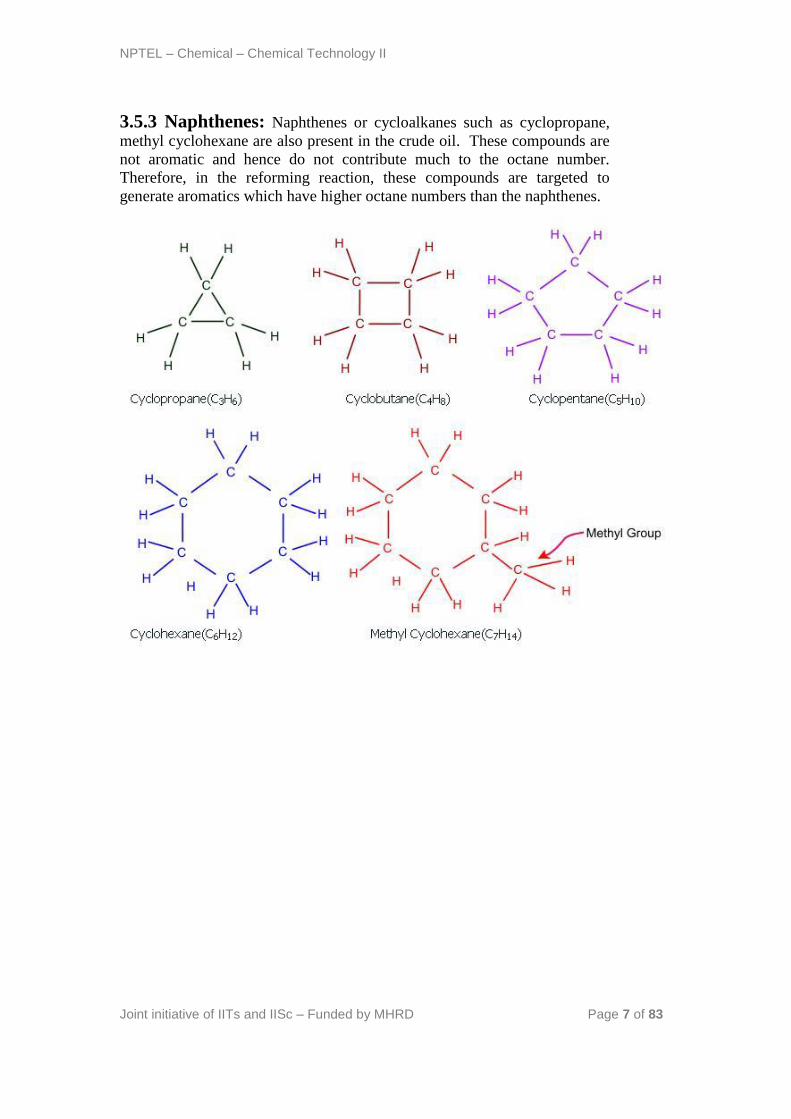
3.5.3 Naphthenes: Naphthenes or cycloalkanes such as cyclopropane,
methyl cyclohexane are also present in the crude oil. These compounds are
not aromatic and hence do not contribute much to the octane number.
Therefore, in the reforming reaction, these compounds are targeted to
generate aromatics which have higher octane numbers than the naphthenes.

NPTEL – Chemical – Chemical Technology II
Joint initiative of IITs and IISc – Funded by MHRD Page 8 of 83
3.5.4 Aromatics: Aromatics such as benzene, toluene o/m/p-xylene are
also available in the crude oil. These contribute towards higher octane
number products and the target is to maximize their quantity in a refinery
process.
3.5.5 Napthalenes: Polynuclear aromatics such as naphthalenes consist
of two or three or more aromatic rings. Their molecular weight is usually
between 150 – 500.
NPTEL – Chemical – Chemical Technology II
Joint initiative of IITs and IISc – Funded by MHRD Page 9 of 83
Organic sulphur compounds: Not all compounds in the crude are
hydrocarbons consisting of hydrogen and carbon only. Organic sulphur
compounds such as thiophene, pyridine also exist in the crude oil. The basic
difficulty of these organic sulphur compounds is the additional hydrogen
requirements in the hydrotreaters to meet the euro III standards. Therefore,
the operating conditions of the hydrotreaters is significantly intense when
compared to those that do not target the reduction in the concentration of
these organic sulphur compounds. Therefore, ever growing environmental
legislations indicate technology and process development/improvement on
the processing of organic sulphur compounds.
3.5.6 Oxygen containing compounds: These compounds do not
exist 2 % by weight in the crude oil. Typical examples are acetic and
benzoic acids. These compounds cause corrosion and therefore needs to be
effectively handled.
3.5.7 Resins: Resins are polynuclear aromatic structures supported with
side chains of paraffins and small ring aromatics. Their molecular weights
vary between 500 – 1500. These compounds also contain sulphur, nitrogen,
oxygen, vanadium and nickel.
3.5.8 Asphaltenes: Asphaltenes are polynuclear aromatic structures
consisting of 20 or more aromatic rings along with paraffinic and
naphthenic chains. A crude with high quantities of resins and asphaltenes
(heavy crude) is usually targeted for coke production.
3.6 Technical Questions:
1. 3.6.1 Explain how crude quality affects the topology of refinery
configuration?
A: This is a very important question. Usually, refinery crudes are
characterized as light, moderate and heavy crudes. Light and moderate
crudes are typically targeted for gas, naphtha, diesel, light and heavy gas oil
fractions. Heavy crudes are targeted for coke and residue product streams.
Therefore, the crude quality does affect the topology of the refinery
configuration. According to the choice of the crude available, refineries are
classified into four types namely
a) Those that target fuels. This is very prominent in a country like India
b) Those that target coke. This is very much targeted for refineries that supply
coke as an important raw materials to other industries such as steel, catalysts
etc.
c) Lubricants.
d) Petrochemicals.
NPTEL – Chemical – Chemical Technology II
Joint initiative of IITs and IISc – Funded by MHRD Page 10 of 83
According to the desired product pallete, the refinery configuration and
hence topology is affected with the crude quality.
2. 3.6.2 What is the basic difference between a chemical and a
refinery process?
A: A chemical process essentially involves streams whose composition is
fairly known. As far as refinery processes are concerned, their chemical
constituents are not exactly known but are estimated as functions of various
measurable properties such as viscosity, cetane number, octane number,
flash point, TBP/ASTM distillation etc.
Therefore, refinery process technology should accommodate the details
pertaining to these issues in addition to the technology issues.
3. 3.6.3 Why are refinery process flow sheets very complex?
A: Well, large refineries involve the production of about 30 to 40 refinery
products with diverse specifications and needs of the consumers. And
necessarily all these products are derived from the crude oil in a complex
way. Due to complicated physical and chemical processes that are
sequentially applied for various refinery process streams, refinery process
flow sheets are very complex.
4. 3.6.4 How to analyze refinery process flow sheets in a simple
way?
Identify
a) Functional role of each process/operation
b) Plausible changes in property characteristics such as octane number or
viscosity etc.
This way refinery technology will be easy to understand with maturity.
5. 3.6.5 Relate the important crude oil cuts and associated
products
a. Gases
iFuel gasii LPG
b. Naphtha
a. Gasoline
b. Jet fuel
c. Kerosene
a. Jet fuel
b. Kerosene
NPTEL – Chemical – Chemical Technology II
Joint initiative of IITs and IISc – Funded by MHRD Page 11 of 83
d. Light gas oil
a. Auto Diesel
b. Tractor Diesel
c. Home heating oil
e. Heavy gas oil
a. Commercial heating oil
b. Industrial heating oil
c. Lubricants
f. Residues
a. Bunker oil
b. Asphalt
c. Coke
References:
1. Gary J.H., Handwerk G.E., Petroleum Refining: Technology and Economics,
Taylor & Francis, 2005
2. Jones D.S.J., Elements of Petroleum Processing, John Wiley & Sons, 1995
NPTEL – Chemical – Chemical Technology II
Joint initiative of IITs and IISc – Funded by MHRD Page 12 of 83
Lecture 4: Overview of Refinery Processes
4.1 Introduction
In this lecture, a brief overview of various refinery processes is presented
along with a simple sketch of the process block diagram of a modern
refinery. The sketch of the modern refinery indicates the underlying
complexity and the sketch is required to have a good understanding of the
primary processing operations in various sub-processes and units.
4.2 Refinery flow sheet
We now present a typical refinery flowsheet for the refining of middle
eastern crude oil. There are about 22 units in the flowsheet which
themselves are complex enough to be regarded as process flow sheets.
Further, all streams are numbered to summarize their significance in various
processing steps encountered in various units. However, for the
convenience of our understanding, we present them as units or blocks which
enable either distillation in sequence or reactive transformation followed by
distillation sequences to achieve the desired products.
The 22 units presented in the refinery process diagram are categorized as
- Crude distillation unit (CDU)
- Vacuum distillation unit (VDU)
- Thermal cracker
- Hydrotreaters
- Fluidized catalytic cracker
- Separators
- Naphtha splitter
- Reformer
- Alkylation and isomerisation
- Gas treating
- Blending pools
- Stream splitters
NPTEL – Chemical – Chemical Technology II
Joint initiative of IITs and IISc – Funded by MHRD Page 13 of 83
A brief account of the above process units along with their functional role is
presented next with simple conceptual block diagrams representing the
flows in and out of each unit.
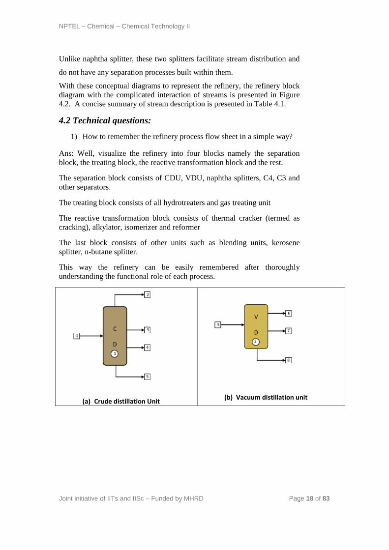
a) Crude distillation unit
The unit comprising of an atmospheric distillation column, side strippers,
heat exchanger network, feed de-salter and furnace as main process
technologies enables the separation of the crude into its various products.
Usually, five products are generated from the CDU namely gas + naphtha,
kerosene, light gas oil, heavy gas oil and atmospheric residue (Figure 4.1a).
In some refinery configurations, terminologies such as gasoline, jet fuel and
diesel are used to represent the CDU products which are usually fractions
emanating as portions of naphtha, kerosene and gas oil. Amongst the crude
distillation products, naphtha, kerosene have higher product values than gas
oil and residue. On the other hand, modern refineries tend to produce
lighter components from the heavy products. Therefore, reactive
transformations (chemical processes) are inevitable to convert the
heavy intermediate refinery streams into lighter streams.
Operating Conditions : The temperature at the entrance of the furnace
where the crude enters is 200 – 280oC. It is then further heated to about
330 – 370oC inside the furnace. The pressure maintained is about 1
barg.
b) Vacuum distillation unit (VDU)
The atmospheric residue when processed at lower pressures does not allow
decomposition of the atmospheric residue and therefore yields LVGO,
HVGO and vacuum residue (Figure 4.1b). The LVGO and HVGO are
eventually subjected to cracking to yield even lighter products. The VDU
consists of a main vacuum distillation column supported with side strippers
to produce the desired products. Therefore, VDU is also a physical process
to obtain the desired products.
Operating Conditions : The pressure maintained is about 25 – 40 mm Hg.
The temperature is kept at around 380 – 420oC.

NPTEL – Chemical – Chemical Technology II
Joint initiative of IITs and IISc – Funded by MHRD Page 14 of 83
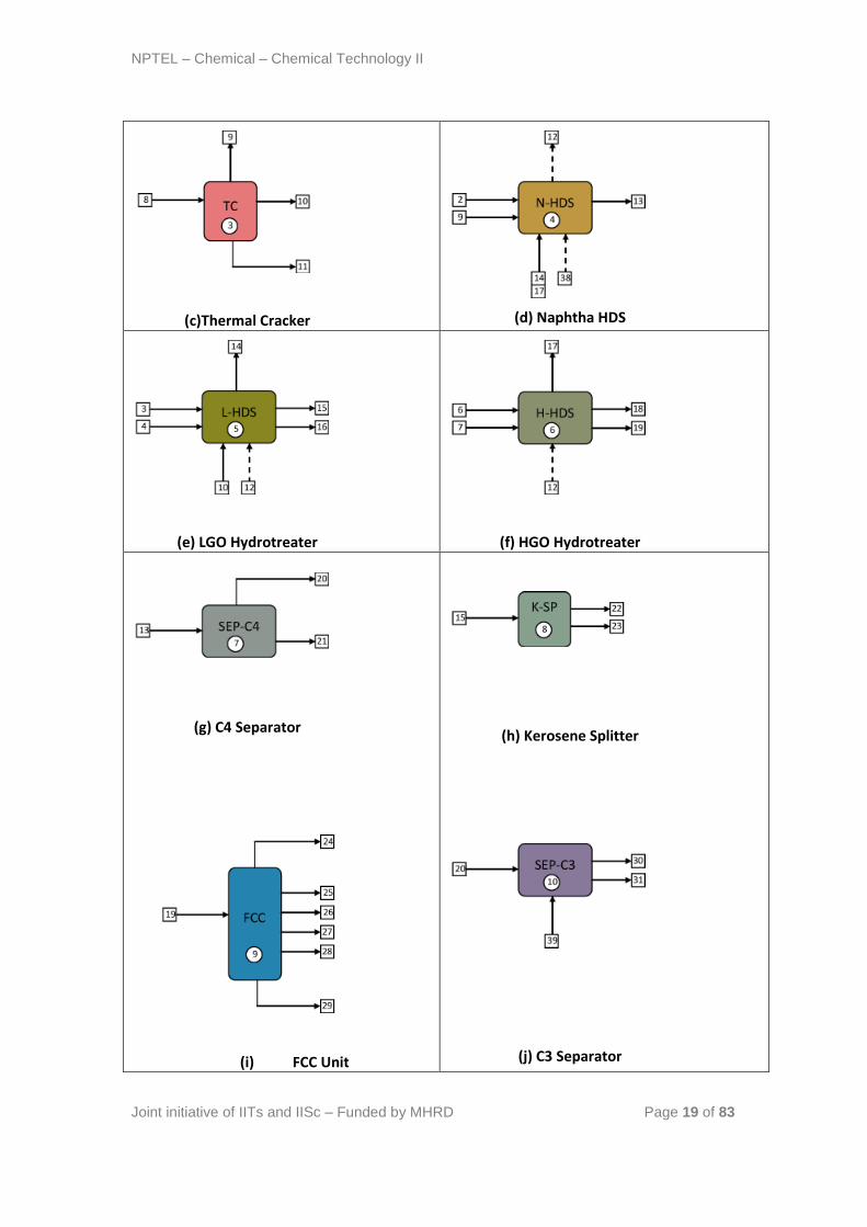
c) Thermal cracker
Thermal cracker involves a chemical cracking process followed by the
separation using physical principles (boiling point differences) to yield the
desired products. Thermal cracking yields naphtha + gas, gasoil and thermal
cracked residue (Figure 4.1c). In some petroleum refinery configurations,
thermal cracking process is replaced with delayed coking process to yield
coke as one of the petroleum refinery products.
Operating Conditions : The temperature should be kept at around 450
– 500oC for the larger hydrocarbons to become unstable and break
spontaneously. A 2-3 bar pressure must be maintained.
d) Hydrotreaters
For many refinery crudes such as Arabic and Kuwait crudes, sulfur content
in the crude is significantly high. Therefore, the products produced from
CDU and VDU consist of significant amount of sulfur. Henceforth, for
different products generated from CDU and VDU, sulfur removal is
accomplished to remove sulfur as H2S using Hydrogen. The H2 required for
the hydrotreaters is obtained from the reformer unit where heavy naphtha is
subjected to reforming to yield high octane number reforme product and
reformer H2 gas. In due course of process, H2S is produced. Therefore, in
industry, to accomplish sulfur removal from various CDU and VDU
products, various hydrotreaters are used. In due course of hydrotreating in
some hydrotreaters products lighter than the feed are produced. For
instance, in the LVGO/HVGO hydrotreater, desulfurization of LVGO &
HVGO (diesel) occurs in two blocked operations and desulfurized naphtha
fraction is produced along with the desulfurized gas oil main product
(Figure 4.1 f). Similarly, for LGO hydrotreating case, along with diesel
main product, naphtha and gas to C5 fraction are obtained as other products
(Figure 4.1e). Only for kerosene hydrotreater, no lighter product is
produced in the hydrotreating operation. It is further interesting to note that
naphtha hydrotreater is fed with both light and heavy naphtha as feed which
is desulfurized with the reformer off gas. In this process, light ends from
NPTEL – Chemical – Chemical Technology II
Joint initiative of IITs and IISc – Funded by MHRD Page 15 of 83
the reformer gas are stripped to enhance the purity of hydrogen to about 92
% (Figure 4.1d). Conceptually, hydrotreating is regarded as a combination
of chemical and physical processes.
Operating Conditions: The operating conditions of a hydrotreater
varies with the type of feed.
For Naphtha feed, the temperature may be kept at around 280-425oC
and the pressure be maintained at 200 – 800 psig.
e) Fluidized catalytic cracker
The unit is one of the most important units of the modern refinery. The unit
enables the successful transformation of desulfurized HVGO to lighter
products such as unsaturated light ends, light cracked naphtha, heavy
cracked naphtha, cycle oil and slurry (Figure 4.1i). Thereby, the unit is
useful to generate more lighter products from a heavier lower value
intermediate product stream. Conceptually, the unit can be regarded as a
combination of chemical and physical processes.
Operating Conditions: The temperature should be maintained at 34oC
with pressure ranging from 75 kPa to 180 kPa. Moreover, the process is
to be carried out in a relatively wet environment.
f) Separators
The gas fractions from various units need consolidated separation and
require stage wise separation of the gas fraction. For instance, C4 separator
separates the desulfurized naphtha from all saturated light ends greater than
or equal to C4s in composition (Figure 4.1g). On the other hand, C3
separator separates butanes (both iso and nbutanes) from the gas fraction
(Figure 4.1j). The butanes thus produced are of necessity in isomerization
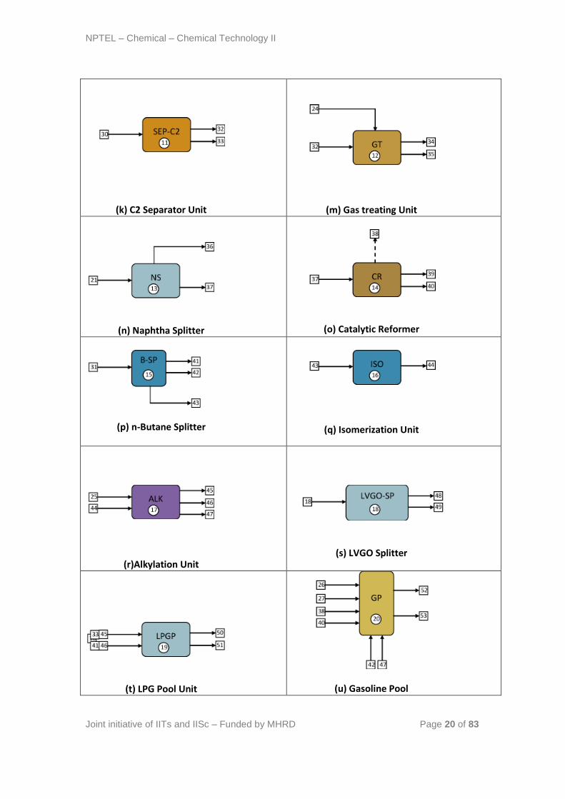
reactions, LPG and gasoline product generation. Similarly, the C2 separator
separates the saturated C3 fraction that is required for LPG product
generation (Figure 4.1k) and generates the fuel gas + H2S product as well.
All these units are conceptually regarded as physical processes.
Operating Conditions: Most oil and gas separators operate in the
pressure range of 20 – 1500 psi.
NPTEL – Chemical – Chemical Technology II
Joint initiative of IITs and IISc – Funded by MHRD Page 16 of 83
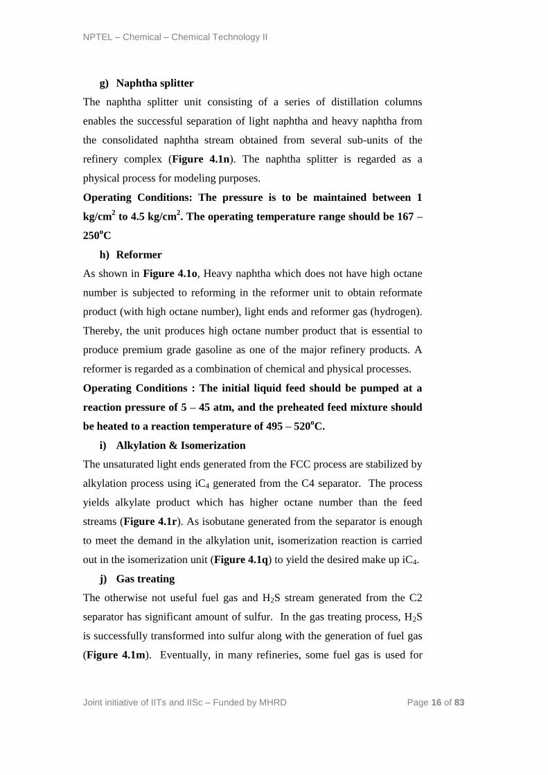
g) Naphtha splitter
The naphtha splitter unit consisting of a series of distillation columns
enables the successful separation of light naphtha and heavy naphtha from
the consolidated naphtha stream obtained from several sub-units of the
refinery complex (Figure 4.1n). The naphtha splitter is regarded as a
physical process for modeling purposes.
Operating Conditions: The pressure is to be maintained between 1
kg/cm2 to 4.5 kg/cm
2. The operating temperature range should be 167 –
250oC
h) Reformer
As shown in Figure 4.1o, Heavy naphtha which does not have high octane
number is subjected to reforming in the reformer unit to obtain reformate
product (with high octane number), light ends and reformer gas (hydrogen).
Thereby, the unit produces high octane number product that is essential to
produce premium grade gasoline as one of the major refinery products. A
reformer is regarded as a combination of chemical and physical processes.
Operating Conditions : The initial liquid feed should be pumped at a
reaction pressure of 5 – 45 atm, and the preheated feed mixture should
be heated to a reaction temperature of 495 – 520oC.
i) Alkylation & Isomerization
The unsaturated light ends generated from the FCC process are stabilized by
alkylation process using iC4 generated from the C4 separator. The process
yields alkylate product which has higher octane number than the feed
streams (Figure 4.1r). As isobutane generated from the separator is enough
to meet the demand in the alkylation unit, isomerization reaction is carried
out in the isomerization unit (Figure 4.1q) to yield the desired make up iC4.
j) Gas treating
The otherwise not useful fuel gas and H2S stream generated from the C2
separator has significant amount of sulfur. In the gas treating process, H2S
is successfully transformed into sulfur along with the generation of fuel gas
(Figure 4.1m). Eventually, in many refineries, some fuel gas is used for
NPTEL – Chemical – Chemical Technology II
Joint initiative of IITs and IISc – Funded by MHRD Page 17 of 83
furnace applications within the refinery along with fuel oil (another refinery
product generated from the fuel oil pool) in the furnace associated to the
CDU.
Operating Conditions: Gas treaters may operate at temperatures
ranging from 150 psig (low pressure units) to 3000 psig (high pressure
units).
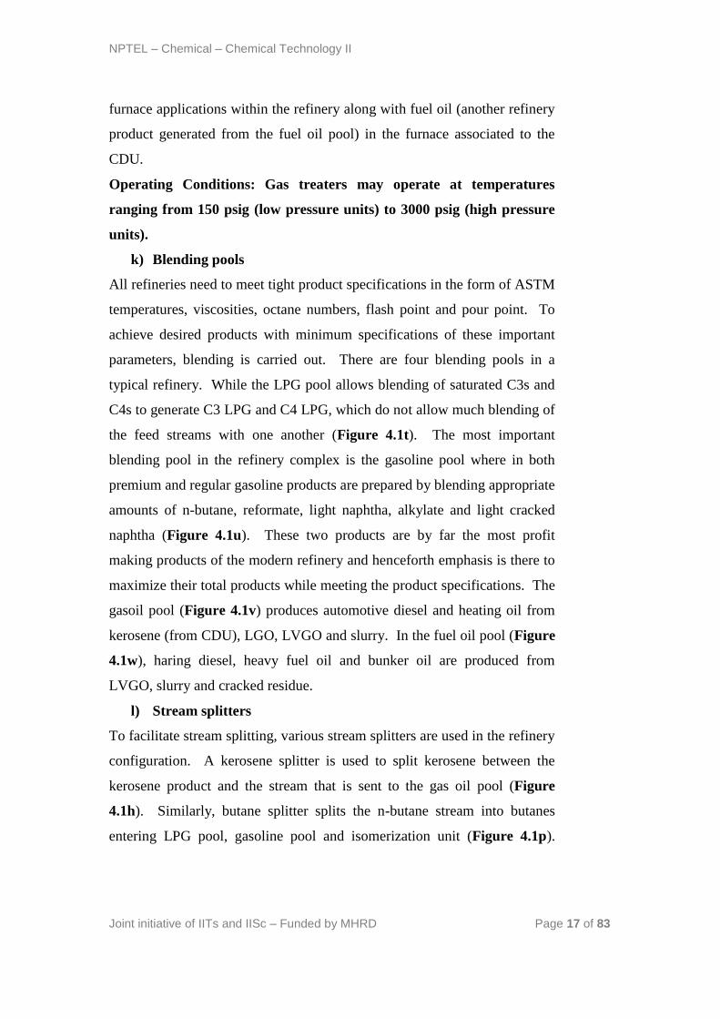
k) Blending pools
All refineries need to meet tight product specifications in the form of ASTM
temperatures, viscosities, octane numbers, flash point and pour point. To
achieve desired products with minimum specifications of these important
parameters, blending is carried out. There are four blending pools in a
typical refinery. While the LPG pool allows blending of saturated C3s and
C4s to generate C3 LPG and C4 LPG, which do not allow much blending of
the feed streams with one another (Figure 4.1t). The most important
blending pool in the refinery complex is the gasoline pool where in both
premium and regular gasoline products are prepared by blending appropriate
amounts of n-butane, reformate, light naphtha, alkylate and light cracked
naphtha (Figure 4.1u). These two products are by far the most profit
making products of the modern refinery and henceforth emphasis is there to
maximize their total products while meeting the product specifications. The
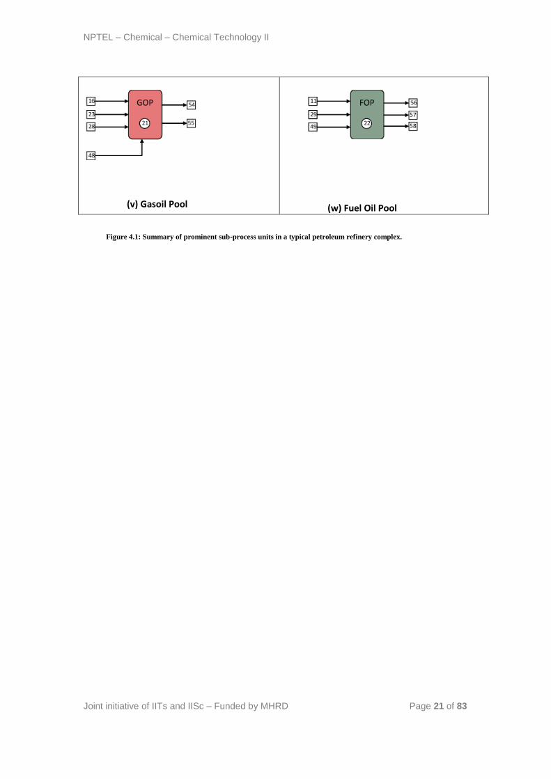
gasoil pool (Figure 4.1v) produces automotive diesel and heating oil from
kerosene (from CDU), LGO, LVGO and slurry. In the fuel oil pool (Figure
4.1w), haring diesel, heavy fuel oil and bunker oil are produced from
LVGO, slurry and cracked residue.
l) Stream splitters
To facilitate stream splitting, various stream splitters are used in the refinery
configuration. A kerosene splitter is used to split kerosene between the
kerosene product and the stream that is sent to the gas oil pool (Figure
4.1h). Similarly, butane splitter splits the n-butane stream into butanes
entering LPG pool, gasoline pool and isomerization unit (Figure 4.1p).
NPTEL – Chemical – Chemical Technology II
Joint initiative of IITs and IISc – Funded by MHRD Page 18 of 83
Unlike naphtha splitter, these two splitters facilitate stream distribution and
do not have any separation processes built within them.
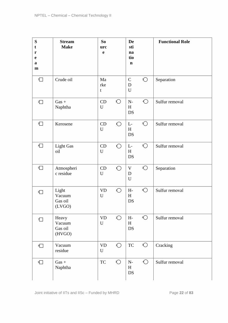
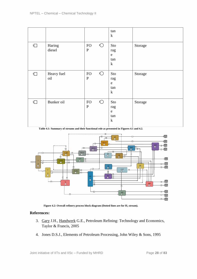
With these conceptual diagrams to represent the refinery, the refinery block
diagram with the complicated interaction of streams is presented in Figure
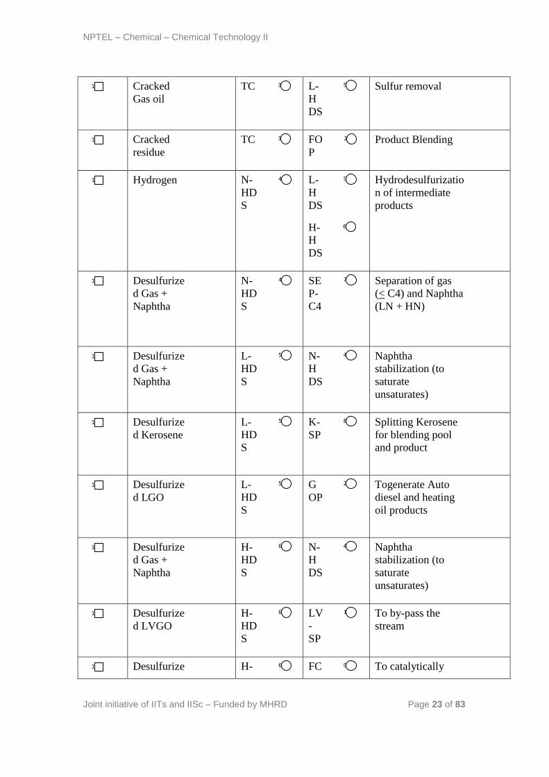
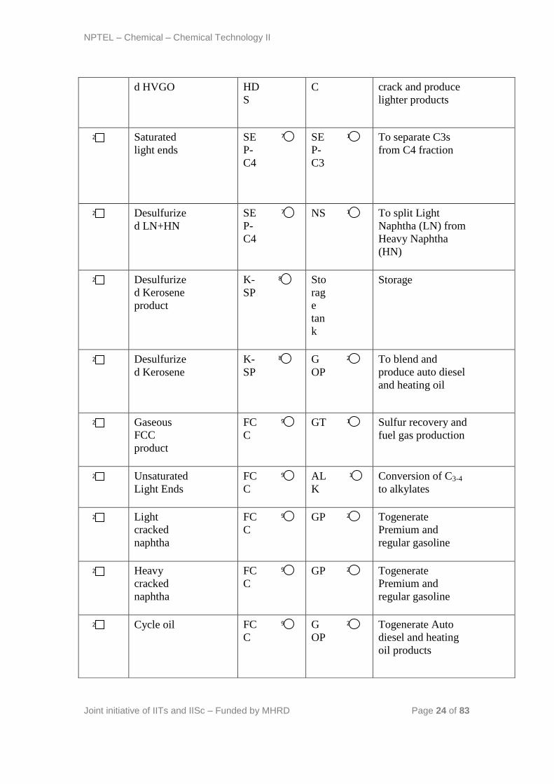
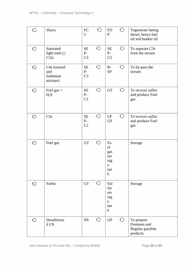
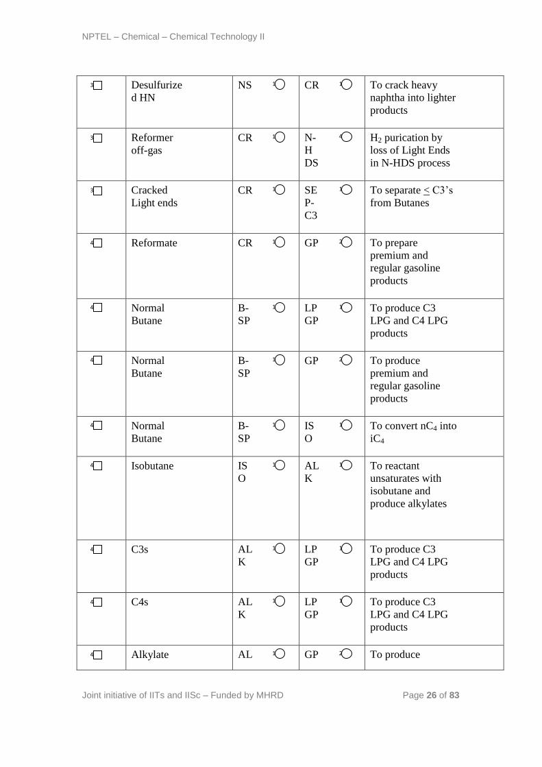
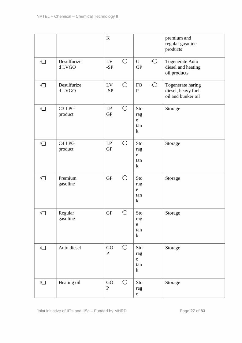
4.2. A concise summary of stream description is presented in Table 4.1.
4.2 Technical questions:
1) How to remember the refinery process flow sheet in a simple way?
Ans: Well, visualize the refinery into four blocks namely the separation
block, the treating block, the reactive transformation block and the rest.
The separation block consists of CDU, VDU, naphtha splitters, C4, C3 and
other separators.
The treating block consists of all hydrotreaters and gas treating unit
The reactive transformation block consists of thermal cracker (termed as
cracking), alkylator, isomerizer and reformer
The last block consists of other units such as blending units, kerosene
splitter, n-butane splitter.
This way the refinery can be easily remembered after thoroughly
understanding the functional role of each process.
(a) Crude distillation Unit
(b) Vacuum distillation unit
NPTEL – Chemical – Chemical Technology II
Joint initiative of IITs and IISc – Funded by MHRD Page 19 of 83
(c)Thermal Cracker
(d) Naphtha HDS
(e) LGO Hydrotreater
(f) HGO Hydrotreater
(g) C4 Separator
(i) FCC Unit
(h) Kerosene Splitter
(j) C3 Separator
NPTEL – Chemical – Chemical Technology II
Joint initiative of IITs and IISc – Funded by MHRD Page 20 of 83
(k) C2 Separator Unit
(m) Gas treating Unit
(n) Naphtha Splitter
(o) Catalytic Reformer
(p) n-Butane Splitter
(q) Isomerization Unit
(r)Alkylation Unit
(s) LVGO Splitter
(t) LPG Pool Unit
(u) Gasoline Pool
NPTEL – Chemical – Chemical Technology II
Joint initiative of IITs and IISc – Funded by MHRD Page 21 of 83
(v) Gasoil Pool
(w) Fuel Oil Pool
Figure 4.1: Summary of prominent sub-process units in a typical petroleum refinery complex.
NPTEL – Chemical – Chemical Technology II
Joint initiative of IITs and IISc – Funded by MHRD Page 22 of 83
S
t
r
e
a
m
Stream
Make
So
urc
e
De
sti
na
tio
n
Functional Role
Crude oil Ma
rke
t
C
D
U
Separation
Gas +
Naphtha
CD
U
N-
H
DS
Sulfur removal
Kerosene CD
U
L-
H
DS
Sulfur removal
Light Gas
oil
CD
U
L-
H
DS
Sulfur removal
Atmospheri
c residue
CD
U
V
D
U
Separation
Light
Vacuum
Gas oil
(LVGO)
VD
U
H-
H
DS
Sulfur removal
Heavy
Vacuum
Gas oil
(HVGO)
VD
U
H-
H
DS
Sulfur removal
Vacuum
residue
VD
U
TC Cracking
Gas +
Naphtha
TC N-
H
DS
Sulfur removal
1 1
2 1 4
3 1 5
4 1 5
5 1 2
6 2 6
7 2 6
8 2 3
9 3 4
NPTEL – Chemical – Chemical Technology II
Joint initiative of IITs and IISc – Funded by MHRD Page 23 of 83
Cracked
Gas oil
TC L-
H
DS
Sulfur removal
Cracked
residue
TC FO
P
Product Blending
Hydrogen N-
HD
S
L-
H
DS
H-
H
DS
Hydrodesulfurizatio
n of intermediate
products
Desulfurize
d Gas +
Naphtha
N-
HD
S
SE
P-
C4
Separation of gas
(< C4) and Naphtha
(LN + HN)
Desulfurize
d Gas +
Naphtha
L-
HD
S
N-
H
DS
Naphtha
stabilization (to
saturate
unsaturates)
Desulfurize
d Kerosene
L-
HD
S
K-
SP
Splitting Kerosene
for blending pool
and product
Desulfurize
d LGO
L-
HD
S
G
OP
Togenerate Auto
diesel and heating
oil products
Desulfurize
d Gas +
Naphtha
H-
HD
S
N-
H
DS
Naphtha
stabilization (to
saturate
unsaturates)
Desulfurize
d LVGO
H-
HD
S
LV
-
SP
To by-pass the
stream
Desulfurize H- FC To catalytically
10
3 5
11
3 22
12
4 5
6
13
4 7
14
5 4
15
8 5
16
21
5
17
6 4
18
18
6
19
9 6
NPTEL – Chemical – Chemical Technology II
Joint initiative of IITs and IISc – Funded by MHRD Page 24 of 83
d HVGO HD
S
C
crack and produce
lighter products
Saturated
light ends
SE
P-
C4
SE
P-
C3
To separate C3s
from C4 fraction
Desulfurize
d LN+HN
SE
P-
C4
NS To split Light
Naphtha (LN) from
Heavy Naphtha
(HN)
Desulfurize
d Kerosene
product
K-
SP
Sto
rag
e
tan
k
Storage
Desulfurize
d Kerosene
K-
SP
G
OP
To blend and
produce auto diesel
and heating oil
Gaseous
FCC
product
FC
C
GT
Sulfur recovery and
fuel gas production
Unsaturated
Light Ends
FC
C
AL
K
Conversion of C3-4
to alkylates
Light
cracked
naphtha
FC
C
GP
Togenerate
Premium and
regular gasoline
Heavy
cracked
naphtha
FC
C
GP
Togenerate
Premium and
regular gasoline
Cycle oil FC
C
G
OP
Togenerate Auto
diesel and heating
oil products
20
7 10
21
7 13
22
8
23
8 21
24
12
9
25
17
9
26
9 20
27
9 20
28
9 21
NPTEL – Chemical – Chemical Technology II
Joint initiative of IITs and IISc – Funded by MHRD Page 25 of 83
Slurry FC
C
FO
P
Togenerate haring
diesel, heavy fuel
oil and bunker oil
Saturated
light ends (<
C3s)
SE
P-
C3
SE
P-
C2
To separate C3s
from the stream
C4s (normal
and
Isobutane
mixture)
SE
P-
C3
B-
SP
To by-pass the
stream
Fuel gas +
H2S
SE
P-
C2
GT
To recover sulfur
and produce Fuel
gas
C3s SE
P-
C2
LP
GP
To recover sulfur
and produce Fuel
gas
Fuel gas GT
Fu
el
gas
sto
rag
e
tan
k
Storage
Sulfur GT Sul
fur
sto
rag
e
tan
k
Storage
Desulfurize
d LN
NS GP To prepare
Premium and
Regular gasoline
products
29
9 22
30
11
10
31
15
10
32
12
11
33
19
11
34
12
35
12
36
20
13
NPTEL – Chemical – Chemical Technology II
Joint initiative of IITs and IISc – Funded by MHRD Page 26 of 83
Desulfurize
d HN
NS CR To crack heavy
naphtha into lighter
products
Reformer
off-gas
CR N-
H
DS
H2 purication by
loss of Light Ends
in N-HDS process
Cracked
Light ends
CR SE
P-
C3
To separate < C3’s
from Butanes
Reformate CR GP To prepare
premium and
regular gasoline
products
Normal
Butane
B-
SP
LP
GP
To produce C3
LPG and C4 LPG
products
Normal
Butane
B-
SP
GP To produce
premium and
regular gasoline
products
Normal
Butane
B-
SP
IS
O
To convert nC4 into
iC4
Isobutane IS
O
AL
K
To reactant
unsaturates with
isobutane and
produce alkylates
C3s AL
K
LP
GP
To produce C3
LPG and C4 LPG
products
C4s AL
K
LP
GP
To produce C3
LPG and C4 LPG
products
Alkylate AL GP To produce
37
14
13
38
14
4
39
10
14
40
20
14
41
15
19
42
15
20
43
15
16
44
17
16
45
19
17
46
19
17
47
20
17
NPTEL – Chemical – Chemical Technology II
Joint initiative of IITs and IISc – Funded by MHRD Page 27 of 83
K premium and
regular gasoline
products
Desulfurize
d LVGO
LV
-SP
G
OP
Togenerate Auto
diesel and heating
oil products
Desulfurize
d LVGO
LV
-SP
FO
P
Togenerate haring
diesel, heavy fuel
oil and bunker oil
C3 LPG
product
LP
GP
Sto
rag
e
tan
k
Storage
C4 LPG
product
LP
GP
Sto
rag
e
tan
k
Storage
Premium
gasoline
GP Sto
rag
e
tan
k
Storage
Regular
gasoline
GP Sto
rag
e
tan
k
Storage
Auto diesel GO
P
Sto
rag
e
tan
k
Storage
Heating oil GO
P
Sto
rag
e
Storage
48
18
21
49
18
22
50
19
51
19
52
19
53
20
54
21
55
21
NPTEL – Chemical – Chemical Technology II
Joint initiative of IITs and IISc – Funded by MHRD Page 28 of 83
Table 4.1: Summary of streams and their functional role as presented in Figures 4.1 and 4.2.
Figure 4.2: Overall refinery process block diagram (Dotted lines are for H2 stream).
References:
3. Gary J.H., Handwerk G.E., Petroleum Refining: Technology and Economics,
Taylor & Francis, 2005
4. Jones D.S.J., Elements of Petroleum Processing, John Wiley & Sons, 1995
tan
k
Haring
diesel
FO
P
Sto
rag
e
tan
k
Storage
Heavy fuel
oil
FO
P
Sto
rag
e
tan
k
Storage
Bunker oil FO
P
Sto
rag
e
tan
k
Storage
56
22
57
22
58
22
NPTEL – Chemical – Chemical Technology II
Joint initiative of IITs and IISc – Funded by MHRD Page 29 of 83
Lecture 5: Crude distillation
5.1 Introduction
In this section, we present a brief overview of the crude distillation process.
The first essential task for the crude oil consisting of more than 108
compounds is to separate its major components based on boiling point
differences. This principle is exploited in the crude distillation unit which
involves energy intensive operation. Since crude distillation involves the
processing of the entire feed, it remains as the most significant operation in
a refinery.
Process flowsheet
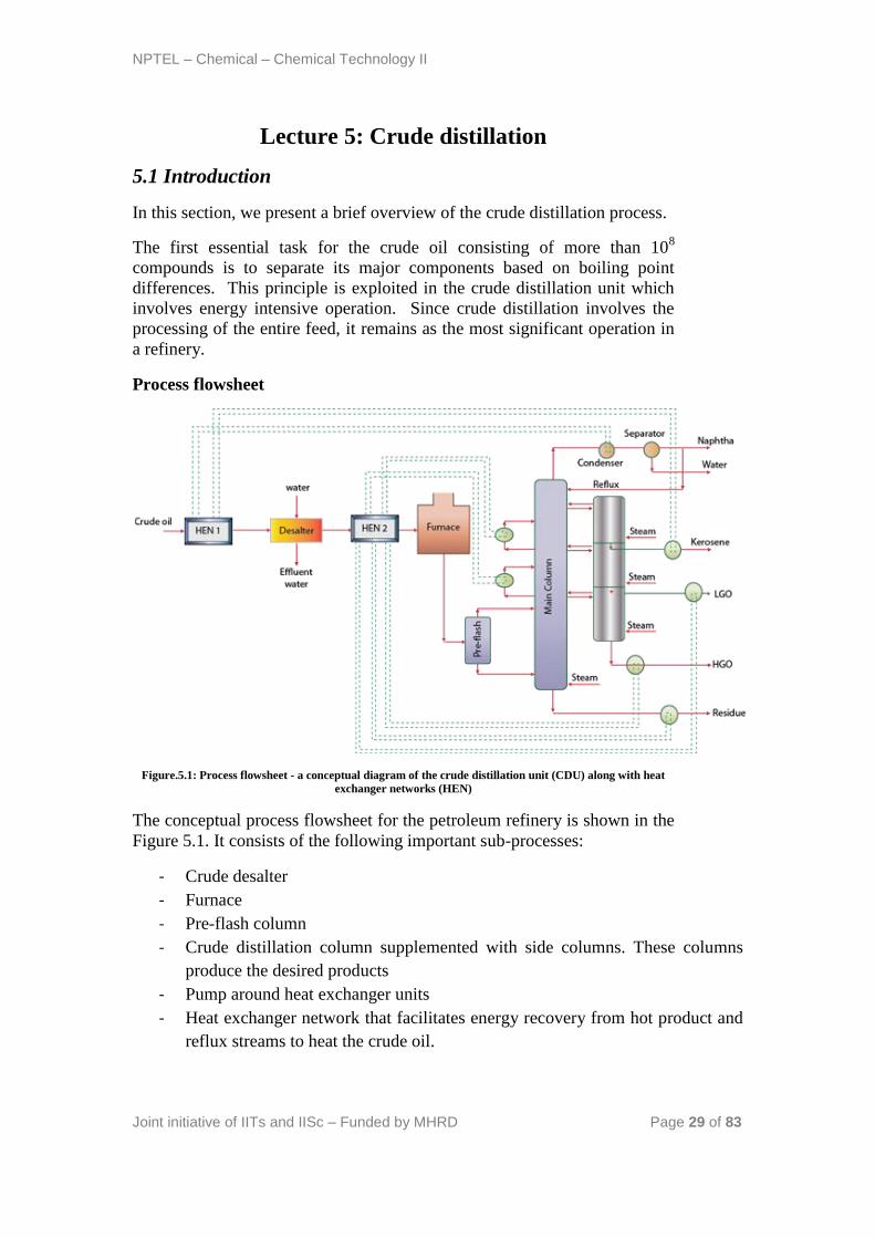
Figure.5.1: Process flowsheet - a conceptual diagram of the crude distillation unit (CDU) along with heat
exchanger networks (HEN)
The conceptual process flowsheet for the petroleum refinery is shown in the
Figure 5.1. It consists of the following important sub-processes:
- Crude desalter
- Furnace
- Pre-flash column
- Crude distillation column supplemented with side columns. These columns
produce the desired products
- Pump around heat exchanger units
- Heat exchanger network that facilitates energy recovery from hot product and
reflux streams to heat the crude oil.

NPTEL – Chemical – Chemical Technology II
Joint initiative of IITs and IISc – Funded by MHRD Page 30 of 83
We next present the functional role of various sub -processes in the crude
distillation unit.
5.1.1 Crude desalter
- Crude oil consists of dissolved salts and they tend to cause fouling and
corrosion in various process equipments. Therefore, dissolved salts need to be
removed using a separation process.
- The crude desalting unit is a separation process. Here, water along with
other trace chemicals such as caustic and acid are allowed to enter a mixing
unit along with the crude oil.
- The mixture of crude oil and water is subsequently passed through an
electrostatic precipitator cum gravity settler. The electrostatic field enables
the agglomeration of water droplets and aids faster gravity settling.
- An essential issue for the good performance of crude desalter is the
temperature of the operation. Usually, high efficiency of salt removal is
possible between 100 – 300 oF.
- Therefore, the crude oil is heated to about 250 oF before it enters the desalter
unit.
- The clean desalted crude oil flows from the top of the gravity settler and the
water along with other dissolved impurities is removed as a bottom product
from the gravity settler unit.
- A high degree of salt removal is desired (95 – 99% removal of the dissolved
salt in the crude oil). Usually, a two stage desalting process is deployed.
When higher salt removal efficiencies are desired, three stage units are
deployed.
5.1.2 Furnace
- The furnace is an important constituent in the crude distillation unit
- Here, fuel oil and fuel gas (heavier products) obtained from the refining
process itself are burnt to increase the crude oil temperature.
- Typically in refineries, the crude oil is heated to a temperature that enables
overflash conditions in the main crude distillation column.
- The concept of overflash is that the crude is heated to such a temperature that
enables an additional 5 % vaporization with respect to the residue product. In
other words, the residue fraction vapors amounting to 5 % of the total volume
of the crude oil are desired.
- Depending upon the quality of the crude, the desired temperature for the crude
oil is about 600 - 700 oF.
NPTEL – Chemical – Chemical Technology II
Joint initiative of IITs and IISc – Funded by MHRD Page 31 of 83
5.1.3 Pre-flash column
- The crude oil enters the pre-flash column after leaving the furnace
- The pre-flash tower separates the lighter fractions of the already heated crude
oil.
- The heavier fractions of the crude oil leave from the bottom section of the pre-
flash tower.
- Both lighter and heavier streams emanating from the pre-flash tower are fed to
the main crude distillation column at various sections
- Pre-flash column enables better refluxes in the main column by distributing
the streams effectively between various processing zones of the crude oil.
- Pre-flash column may or may not be included i.e., it is optional. In other
words, the pre-flash column can be avoided and the heated crude oil from the
furnace can be fed to the main column directly.
5.1.4 Main and Secondary distillation columns
- The distillation columns consisting of both main and secondary crude
distillation columns are one of the most complex circuitries in distillation.
- The complex arrangement of distillation columns is based on research carried
out with pilot plants and simulation software.
- The crude distillation columns (both main and primary) are regarded to an
indirect sequence of thermally coupled distillation sequences to obtain the
desired products.
- Effective distribution of vapor and reflux in the main column is a serious
issue.
- The effective distribution of vapor and reflux is aided through pump around
heat exchanger units.
- Live steam is also used in the recent designs. The live steam is usually at
about 50 psig.
- The basic principle of using live steam stems out from several facts. Firstly,
upon condensation, oil and water are very easy to separate. Secondly, steam
can take significant amount of heat in terms of enthalpy. Thirdly, steam
enables enhancement in relative volatility, a principle that is used in steam
distillation laboratory experimental set ups. These principles together are
anticipated to provide good dividends technically.
- Live steam cannot be just fed at one section of the CDU. It needs to be fed at
various sections to ensure both good heat distribution and reduce relative
volatilities of the hydrocarbons at various sections of the main and secondary
towers.

NPTEL – Chemical – Chemical Technology II
Joint initiative of IITs and IISc – Funded by MHRD Page 32 of 83
- Therefore, live steam will enable good product quality as lighter hydrocarbons
with higher relative volatilities in the bottom heavy product liquid streams will
be easily stripped and carried along with the vapor.
- The only condenser in the main column is a partial condenser to facilitate the
production of both gas and naptha+water stream.
- The circuitry totally avoided the existence of reboilers by introducing live
steam. Therefore, much fixed costs of the column have been reduced.
However, higher operating costs due to higher steam utilization rates are
evident.
5.1.5 Pump-around units
- Pump around units are most essential units in the crude distillation column.
- They are used to maintain good reflux conditions in the main column and
therefore the desired product quality.
- They also provide a good heat source as the liquid streams are at higher
temperatures. Therefore, they are also important units in the heat exchanger
network.
- The cooled liquid is sent back to a section above.
- Usually two pump arounds are used in conventional designs. However, there
are crude distillation units with even three pump around units.
The circuitry connections between primary and secondary towers along with
relevant pump around units are presented in Figure5. 2. It can be seen that
very complex interactions exists between the main and secondary columns.
NPTEL – Chemical – Chemical Technology II
Joint initiative of IITs and IISc – Funded by MHRD Page 33 of 83
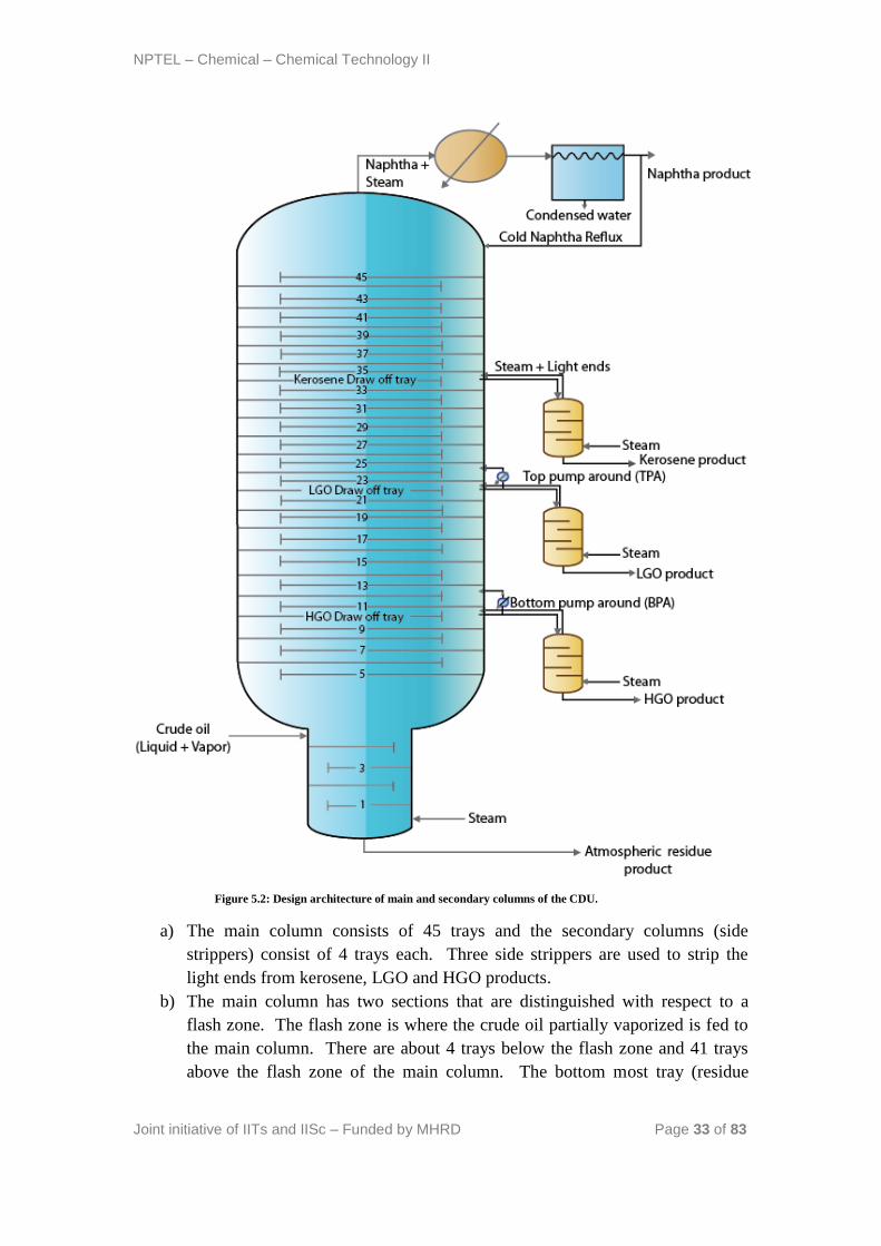
Figure 5.2: Design architecture of main and secondary columns of the CDU.
a) The main column consists of 45 trays and the secondary columns (side
strippers) consist of 4 trays each. Three side strippers are used to strip the
light ends from kerosene, LGO and HGO products.
b) The main column has two sections that are distinguished with respect to a
flash zone. The flash zone is where the crude oil partially vaporized is fed to
the main column. There are about 4 trays below the flash zone and 41 trays
above the flash zone of the main column. The bottom most tray (residue
NPTEL – Chemical – Chemical Technology II
Joint initiative of IITs and IISc – Funded by MHRD Page 34 of 83
stripping tray) is numbered as 1 and the top tower tray is numbered as 45.
Trays 1 to 4 process the atmospheric residue portion of the crude in the section
below the flash zone.
c) Trays 5 to 10 (6 trays above the flash zone) process the HGO product portion
of the crude. From tray 10, HGO draw off product is taken out (as liquid) and
enters the HGO side stripper unit. From tray 10 as well, the liquid stream is
drawn and sent to tray 12 via a bottom pump around unit that enables cooling
of the liquid stream. The steam + light ends from the HGO side stripper enter
tray 11 of the main column.
d) Trays 13 to 22 (10 trays above the HGO processing zone) process the LGO
product portion of the crude. From tray 22, LGO draw off product is taken (as
liquid) and sent to the LGO side stripper unit. Also, from tray 22, another
liquid stream is taken out and sent to tray 24 via a top pump around unit (TPA)
that enables cooling of the liquid stream. The steam + light ends from the
LGO side stripper enter tray 23 of the main column.
e) Trays 24 to 34 (10 trays above the LGO processing zone) process the kerosene
product portion of the crude. From tray 34, the kero draw off stream is taken
and sent to the kerosene side stripper unit. The steam + light ends of the
kerosene side stripper enter tray 35.
f) Trays 34 to 45 (12 trays above the Kerosene processing zone) process the
naphtha product portion of the crude. It is interesting to note that tray 34 is
regarded as a tray processing both LGO as well as naphtha processing
zone. This is because there is no pump around associated to the tray 34.
Where pump around is associated, that tray is often ignored in counting,
as it affects to a large extent the tray hydraulics and contributes less
towards the separation of the components.
g) It is interesting to note that steam enters main column at trays 1, 11, 23, 35 and
therefore is present along with the vapor stream along with the hydrocarbons.
Therefore, steam balances throughout the column are very important.
h) The cold naphtha stream obtained from the phase separator is sent back to the
main column as reflux stream.
NPTEL – Chemical – Chemical Technology II
Joint initiative of IITs and IISc – Funded by MHRD Page 35 of 83
5.1.6 Heat exchanger networks
- Two heat exchanger networks exist in the crude distillation unit, one before
the crude desalter and one after the crude desalter.
- The heat exchanger networks facilitate energy recovery from hot product,
naphtha+steam vapor and reflux streams to heat the crude oil in an indirect
heat transfer mode i.e, using heat exchangers.
- Therefore, the design and operation of a heat exchanger network is very
important in the crude distillation unit.
- Further, it needs to be understood that the naphtha heat integrated condenser is
a partial condenser where as all others are heat exchangers without any phase
change streams.
- The heat exchanger networks enable to increase the crude oil stream
temperature to about 200 – 230 oC which is significantly higher than the crude
oil source temperature (about 20 – 30 oC).
- Crude distillation units without heat exchanger networks have higher furnace
load targets. They also cause more pollution due to burning more fuel oil and
fuel gas streams.
5.2 Technical questions
1. What is the most important aspect of main column in the CDU?
Ans: The column hydraulics with a good distribution of liquid and vapor in
the CDU is the most important aspect. The entire concept of live steam at
various sections, top and bottom pump arounds, over-flash is centered
around this designed basic feature.
2. What similarities are there for the CDU with vacuum distillation unit?
Ans:: Both crude and vacuum distillation units have similar architecture of
the main and secondary columns i.e., both have complex stream circuitries
with pump arounds, heat exchanger networks and utilization of steam. Only
basic difference is that while we operate the VDU at lower pressure (30 – 40
mm Hg), the operating temperatures will be lower than those in the CDU.
Otherwise, the basic principles remain the same.
3. What primary disadvantage exists by using live steam in the CDU
columns?
- Live steam once it enters the column does not condense anywhere, as we
don’t want any condensation to happen.
- When live steam is used, vapor load increases significantly in the column
NPTEL – Chemical – Chemical Technology II
Joint initiative of IITs and IISc – Funded by MHRD Page 36 of 83
- This increases the diameter of the column at various sections. There will
be ofcourse a section that has maximum vapor load and this section will
have the maximum diameter.
References:
5. Gary J.H., Handwerk G.E., Petroleum Refining: Technology and Economics,
Taylor & Francis, 2005
6. Jones D.S.J., Elements of Petroleum Processing, John Wiley & Sons, 1995
NPTEL – Chemical – Chemical Technology II
Joint initiative of IITs and IISc – Funded by MHRD Page 37 of 83
Lecture 6: Cracking
6.1 Introduction
A critical observation of the overall refinery process block diagram
indicates that the straight run gasoline (this is the gasoline obtained from the
CDU) does not have good octane number (40 – 60) and needs to be
upgraded to obtain the desired octane number (85 – 95).
Typically, cracking, reforming and isomerisation are regarded as the three
most important processes that contribute towards upgradation of the octane
number.
In this lecture, we present an overview of the cracking operation in the
refinery.
Typically cracking involves the thermal or catalytic decomposition of
petroleum fractions having huge quantities of higher molecular weight
compounds. Since heat is required, typically cracking reactions are carried
out in furnaces that are supplied with either fuel oil or fuel gas or natural gas
or electricity as heat source. Cracking facilitates initiation, propagation and
termination reactions amongst the hydrocarbon themselves. However, when
steam cracking is carried out, in addition to the energy supplied by the direct
contact of steam with the hydrocarbons, steam also takes part in the reaction
to produce wider choices of hydrocarbon distribution along with the
generation of H2 and CO.
6.2 What is cracking?
- Cracking involves the decomposition of heavier hydrocarbon feedstocks to
lighter hydrocarbon feed stocks.
- Cracking can be carried out to any hydrocarbon feedstock but it is usually
applied for vacuum gas oil (VGO)
- Cracking can be with or without a catalyst.
- When cracking is carried out without a catalyst higher operating temperatures
and pressures are required. This is called as thermal cracking. This was the
principle of the old generation refineries.
- Now a days, cracking is usually carried out using a catalyst. The catalyst
enabled the reduction in operating pressure and temperature drastically.
6.3 Cracking chemistry
- Long chain paraffins converted to olefins and olefins
- Straight chain paraffins converted to branched paraffins
- Alkylated aromatics converted to aromatics and paraffins
- Ring compounds converted to alkylated aromatics
NPTEL – Chemical – Chemical Technology II
Joint initiative of IITs and IISc – Funded by MHRD Page 38 of 83
- Dehydrogenation of naphthenes to aromatics and hydrogen
- Undesired reaction: Coke formation due to excess cracking
- Cracking is an endothermic reaction
Therefore, in principle cracking generates lighter hydrocarbons constituting
paraffins, olefins and aromatics. In other words, high boiling low octane
number feed stocks are converted to low boiling high octane number
products.
6.4 Operating conditions
- These very much depend upon the feed stock and type of cracking (thermal
/catalytic ) used.
- Cracking is a gas phase reaction. Therefore, entire feedstock needs to be
vaporized.
- It was observed that short reaction times (to the order of 1 – 3 seconds only)
provide good quality product and less coke formation.
- For vacuum gas oil, thermal cracking requires operationg at 600 oC and 20
atms gauge pressure.
- For vacuum gas oil, catalytic cracking is usually carried out at 480 oC and 0.7
– 1 atms gauge pressure.
6.5 Catalyst
- Acid treated silica-alumina was used as catalyst.
- 20 – 80 mesh size catalysts used for FCCR and 3 – 4 mm pellets used for
MBRs
- During operation, poisoning occurs with Fe, Ni, Vd and Cu
NPTEL – Chemical – Chemical Technology II
Joint initiative of IITs and IISc – Funded by MHRD Page 39 of 83
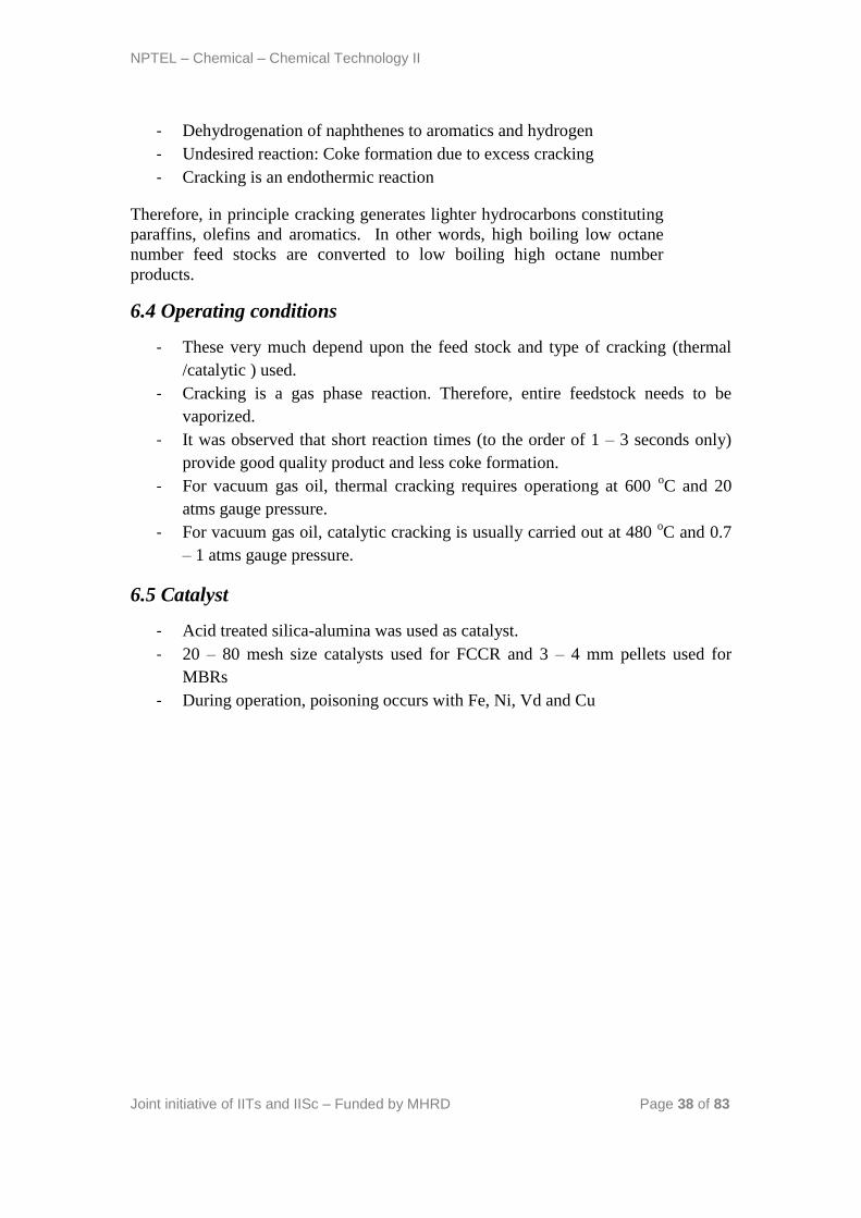
6.6 Process technology
The process technology consists of two flowsheets namely the cracking
coupled with main distillation column and stabilization of naphtha.
Figure6.1 Flow sheet of Catalytic Cracking process
- Feed enters the cracking reactor.
- Old generation refineries used moving bed reactors
- Now a days, fluidized catalytic cracking (FCC) reactors are used.
- The cracked product from the reactor enters a main distillation column that
produces unstabilized naphtha, light gas oil, heavy gas oil, slurry and gas.

NPTEL – Chemical – Chemical Technology II
Joint initiative of IITs and IISc – Funded by MHRD Page 40 of 83
Figure6.2 Naphtha stabilization flow sheet
- The naphtha obtained is unstabilized, as it consists of various hydrocarbons. It
is therefore subjected to stabilized by continued processing.
- The slurry enters a phase separation unit which separates decant oil and a
heavier product. The heavier product is recycled back to the cracking reactor.
- The unstabilized naphtha subsequently enters a unsaturates gas plant
- In the unsaturates gas plant, the gas obtained from the main distillation column
is sent to a phase separator. The phase separator separates lighter
hydrocarbons from heavier hydrocarbons.
- The phase separator is also fed with the unstabilized naphtha. The unstabilized
naphtha from the main column is first fed to a primary absorber to absorb
heavier hydrocarbons in the gas stream emanating from the phase separator.
- The gas leaving the primary absorber is sent to a secondary absorber where
light gas oil from main distillation column is used as a absorbent to further
extract any absorbable hydrocarbons into the light gas oil. Eventually, the rich
light gas oil enters the main distillation column (not shown in the figure a).
- The naphtha generated from the phase separator is sent to stripping to further
consolidate and stabilize naphtha
- The stabilized naphtha is further subjected to distillation in debutanizer and
depropanizer units
NPTEL – Chemical – Chemical Technology II
Joint initiative of IITs and IISc – Funded by MHRD Page 41 of 83
- The debutanizer unit removes butanes and lower hydrocarbons from the
naphtha. The naphtha obtained as bottom product in the debutanizer is termed
as debutanized stable naphtha or gasoline.
- The butanes and other hydrocarbons are sent to a depropanizer unit where
butanes are separated from propanes and other lighter hydrocarbons. Thus,
butanes are obtained as lower product and propanes along with other lighter
hydrocarbons are obtained as the top product in the depropanizer unit.
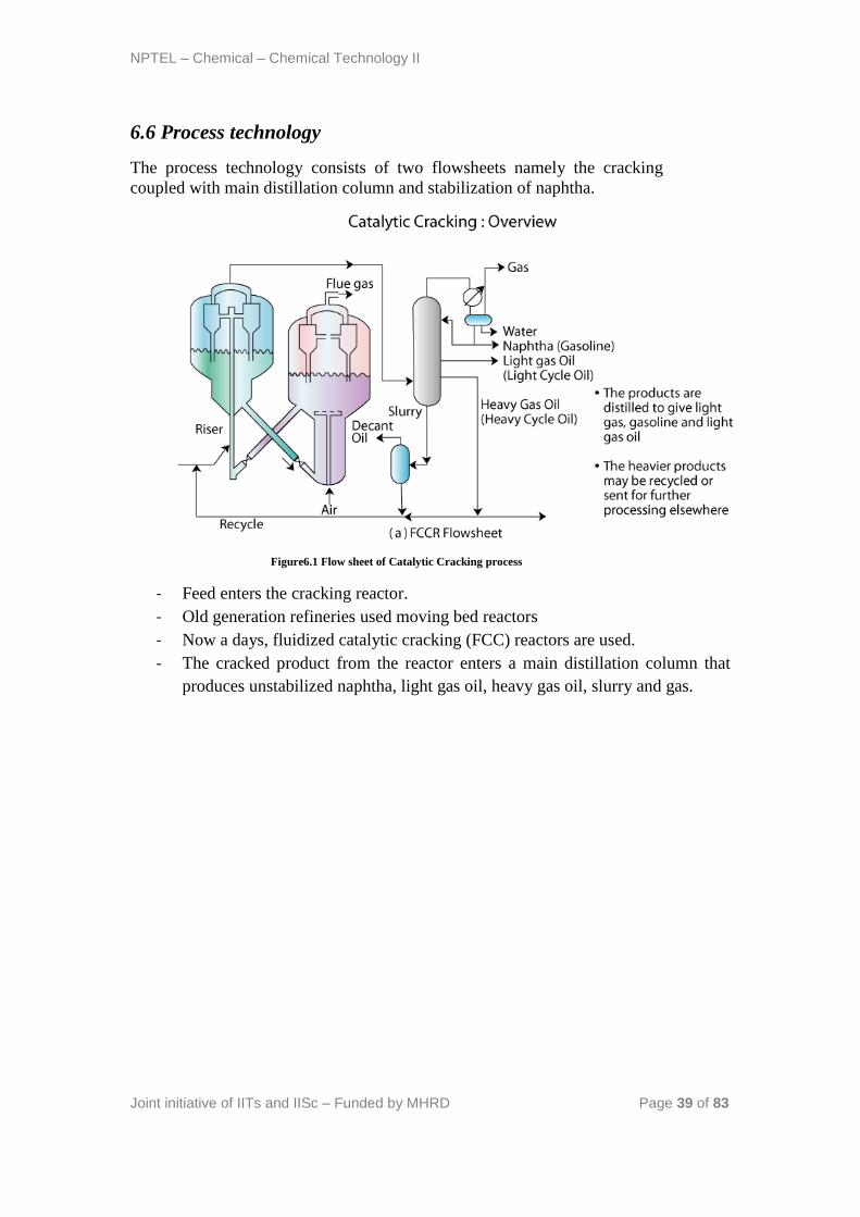
6.7 Fluidized catalytic cracking reactor (FCCR) (Figure 6.3)
Figure6.3 Fluidized Catalytic Cracking Reactor
- The basic principle of the FCCR is to enable the fluidization of catalyst
particles in the feed stream at desired pressure and temperature.
- Another issue for the FCCR is also to regenerate the catalyst by burning off
the coke in air.
- Therefore, the reactor unit should have basically two units namely a reactor
(FCCR) and a catalyst regenerator (CR).
- The FCCR consists essentially of two important components in a sophisticated
arrangement. These are the riser and the cyclone unit assembled in a reactor
vessel.
- Riser: In the riser (a long tube), the feed is allowed to get in contact with the
hot catalyst. The hot catalyst is enabled to rise through lift media in the riser.
The lift media is usually steam or light hydrocarbon gas.
- The riser contact time is about 250 milliseconds.
- The riser is eventually connected to cyclone units.
NPTEL – Chemical – Chemical Technology II
Joint initiative of IITs and IISc – Funded by MHRD Page 42 of 83
- The cyclone units receive the catalyst and finished product. The catalyst that
enters the cyclone unit is fully coked and needs to be sent to a regenerator to
regain its lost activity.
- After cyclone operation (which separates the hydrocarbon vapors and catalyst
as a solid fluid operation), the catalyst falls down to the vessel that houses the
riser and cyclone units.
- The catalyst in the vessel is subjected to stream stripping in which direct
contact with steam is allowed to remove hydrocarbons from the catalyst
surface.
6.8 Catalyst regenerator (CR)
- The spent catalyst which is relatively cold enters the regenerator unit.
- Here air enters the vessel through a sparger set up.
- The catalyst is subsequently burnt in the air. This enables both heating the
catalyst (which is required to carry out the endothermic reaction) and
removing the coke so as to regain the activity of the coke.
- The catalyst + air after this operation will enter the cyclone separator unit.
Unlike the FCCR, the CR does not have a riser. Therefore, air enters a dense
phase of catalyst and also enables the movement of the catalyst to a dilute
phase of catalyst + air
- The cyclone separators separate the flue gas and catalyst as a solid fluid
operation.
- The activity regained catalyst is sent to the riser through a pipe.
- During this entire operation, the catalyst temperature is increased to 620 – 750 oC
- The flue gas is obtained at 600 -760 oC and is sent for heat recovery unit to
generate steam.
NPTEL – Chemical – Chemical Technology II
Joint initiative of IITs and IISc – Funded by MHRD Page 43 of 83
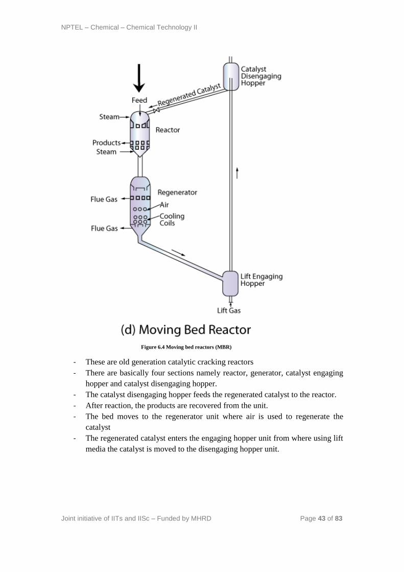
Figure 6.4 Moving bed reactors (MBR)
- These are old generation catalytic cracking reactors
- There are basically four sections namely reactor, generator, catalyst engaging
hopper and catalyst disengaging hopper.
- The catalyst disengaging hopper feeds the regenerated catalyst to the reactor.
- After reaction, the products are recovered from the unit.
- The bed moves to the regenerator unit where air is used to regenerate the
catalyst
- The regenerated catalyst enters the engaging hopper unit from where using lift
media the catalyst is moved to the disengaging hopper unit.
NPTEL – Chemical – Chemical Technology II
Joint initiative of IITs and IISc – Funded by MHRD Page 44 of 83
6.9 Technical questions
1. Why the naphtha stream after absorption and phase separation enters a
stripping unit?
Ans: The stabilization process involves enabling naphtha to possess only
those components that do not flash off in due course of storage. Therefore,
naphtha possessing any lighter hydrocarbons other than those desired should
be totally eliminated. The unstabilized naphtha obtained from the main
distillation column is not given enough time to equilibriate towards
stabilization cause. Even after the phase separator and absorber units, the
stabilization needs one more unit for processing and hence a stripper unit is
used to remove any lighter gases that exist after phase separation.
It is further interesting to note that phase separators do not always meet the
product requirements. The phase separators only enable the separation of
gas and liquid streams based on their operating temperature and pressure
which may not correspond to the exact conditions required to equilibrate.
Therefore, additional processing is mandatory.
2. Why steam stripping is carried out in the FCCR?
Ans: The purpose of stream stripping is to facilitate the removal of
hydrocarbons adsorbed on the catalyst surface. If this is not done, they will
be burnt in the CR unit and this will be loss of product value. In petroleum
processing, always we don’t wish to loose any valuable money in the
processing. That’s also the reason why the flue gas from CR is sent to the
flue gas heat recovery unit for steam generation.
3. Comment on process intensification in the FCCR?
Ans: The FCCR is a complicated arrangement of the riser (where the
reaction takes place), the cyclone separator (where solid fluid separation
takesplace) and the stripper (where again stripping the catalyst takes place a
physical process). Therefore, we can see that the reactor and separator are
packed into a single vessel applying the finer principles of process
intensification.
4. What are the main advantages of catalytic cracking over thermal
cracking?
- Good product quality
- Less coke formation
- Temperature and pressure uniformity in operation
NPTEL – Chemical – Chemical Technology II
Joint initiative of IITs and IISc – Funded by MHRD Page 45 of 83
5. What are the advantages of FCCRs with respect to MBRs?
- Uniformity in heat and mass transfer (fluidization)
- Compact design
- Lower erosion
- Lower steam requirements
- Higher steam efficiency
References:
7. Gary J.H., Handwerk G.E., Petroleum Refining: Technology and Economics,
Taylor & Francis, 2005
8. Jones D.S.J., Elements of Petroleum Processing, John Wiley & Sons, 1995
NPTEL – Chemical – Chemical Technology II
Joint initiative of IITs and IISc – Funded by MHRD Page 46 of 83
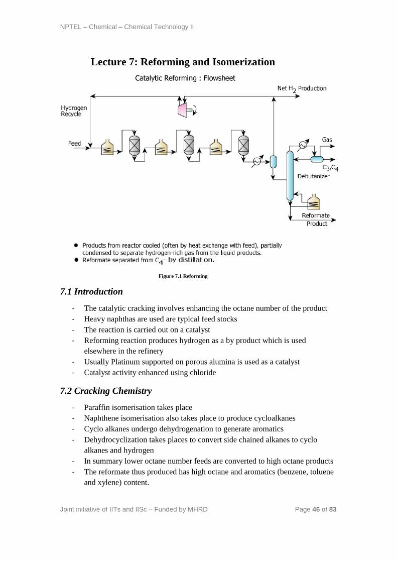
Lecture 7: Reforming and Isomerization
Figure 7.1 Reforming
7.1 Introduction
- The catalytic cracking involves enhancing the octane number of the product
- Heavy naphthas are used are typical feed stocks
- The reaction is carried out on a catalyst
- Reforming reaction produces hydrogen as a by product which is used
elsewhere in the refinery
- Usually Platinum supported on porous alumina is used as a catalyst
- Catalyst activity enhanced using chloride
7.2 Cracking Chemistry
- Paraffin isomerisation takes place
- Naphthene isomerisation also takes place to produce cycloalkanes
- Cyclo alkanes undergo dehydrogenation to generate aromatics
- Dehydrocyclization takes places to convert side chained alkanes to cyclo
alkanes and hydrogen
- In summary lower octane number feeds are converted to high octane products
- The reformate thus produced has high octane and aromatics (benzene, toluene
and xylene) content.
NPTEL – Chemical – Chemical Technology II
Joint initiative of IITs and IISc – Funded by MHRD Page 47 of 83
- The reactions are endothermic. Therefore, heat needs to be supplied
7.3 Process technology (Figure 7.1)
- The feed is mixed with recycled hydrogen
- Subsequently, it is heated before sending to reactor
- Since the reactions are highly endothermic, several combinations of reactor +
heaters are used.
- The products from the final reactor are cooled. Often this is carried out with
heat recovery principle in which heat is recovered using the fresh feed to the
first reactor.
- After this, the product mixture enters a phase separator which separates the
hydrogen gas stream from the liquid stream.
- The liquid stream from the phase separator is sent to a debutanizer distillation
column that separates butanes and lower alkanes from the reformate product.
- The hydrogen produced in the phase separator is compressed and sent back to
the first reactor.
- Excess hydrogen generated in the reactions is taken out as a bleed stream
- Catalyst regeneration (not shown in the flow sheet) needs to be carried out to
regain catalyst activity. This can be in different modes of operation namely
cyclic, semi-regenerative or continuous. When continuous mode of catalyst
regeneration is carried out (as in UOP continuous catalytic reforming process),
the moving bed designs are used for the reforming reactor. Additional
complexity in the moving bed reactors is to enable process intensification to
club the sequence of three reactors + heaters into one single unit.
NPTEL – Chemical – Chemical Technology II
Joint initiative of IITs and IISc – Funded by MHRD Page 48 of 83
7.4 Process parameters
- Reactor pressure: 4 – 24 barg
- Reactor temperature: 500 – 525 oC
- H2/Hydrocarbon molar ratio: 2 – 3
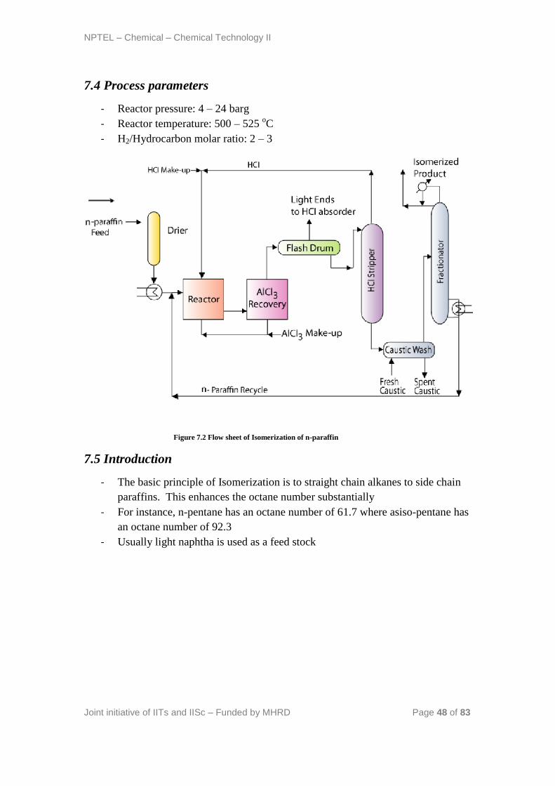
Figure 7.2 Flow sheet of Isomerization of n-paraffin
7.5 Introduction
- The basic principle of Isomerization is to straight chain alkanes to side chain
paraffins. This enhances the octane number substantially
- For instance, n-pentane has an octane number of 61.7 where asiso-pentane has
an octane number of 92.3
- Usually light naphtha is used as a feed stock
NPTEL – Chemical – Chemical Technology II
Joint initiative of IITs and IISc – Funded by MHRD Page 49 of 83
7.6 Catalyst
- Platinum base catalysts are used
- AlCl3 is used as a promoter for the catalyst
- During reaction, part of the AlCl3 gets converted to HCl
- Therefore, completely dry conditions shall be maintained to avoid catalyst
deactivation and corrosion.
- Catalytic reaction takes place in the presence of hydrogen to suppress coke
formation
7.7 Process technology (Figure 7.2)
- Light naphtha and hydrogen (make up) are totally dried and sent to an
isomerisation reactor after pre-heating the feed mixture in a heat exchanger
- Reaction operating conditions: 150 – 200 oC and 17 – 28 barg
- Typical conversions: 75 – 80 % for pentanes.
- After reaction, AlCl3 is recovered from the product using condensation or
distillation
- The basic principle for AlCl3 recovery is that at the reactor operating
conditions, the AlCl3 is in volatile conditions and is soluble in hydrocarbons
- After AlCl3 is recovered from the product, it is sent back to the reactor along
with the make- up AlCl3
- Eventually, the product enters a flash drum where bulkly light ends along with
little quantities of HCl are separated from the liquid product.
- The light ends recovered from the flash drum are sent to aHCl absorber where
HCl is absorbed into caustic solution to generate the light end gases. The light
end gases can be further used for other processes in the refinery.
- The bottom product then enters aHCl stripper where most of the HCl is
stripped from the isomerisation product rich stream. The HCl is recycled back
to the reactor to ensure good catalyst activity. Make-up HCl is added to
account for losses
- Subsequently, caustic wash is carried out to remove any trace quantities of
HCl
- The isoermized product rich stream is then sent to a fractionators that
separates the isomerized product from the unreacted feed.
- The unreacted feed from the fractionators is sent back to the reactor.
NPTEL – Chemical – Chemical Technology II
Joint initiative of IITs and IISc – Funded by MHRD Page 50 of 83
7.8 Technical questions
1. Why is hydrogen used in the reforming reaction?
Ans: Hydrogen reduces the coke formation on the catalyst and therefore
increases the shell life of the highly expensive platinum catalyst.
2. Why is reforming a very important process in the refinery?
Ans: The reforming is one of the most important operation in the refinery to
enhance product quality. Further, the total hydrogen requirement in the
refinery for various hydrotreaters is produced in the reforming process.
Therefore, the reformer contributes to both most important requirements of
the refinery.
3. Looking at the process flow-sheet of the reforming and isomerisation
process, what insights you gain towards the flowsheet evolution?
Ans: Both reforming and isomerisation flow sheets are typical examples of
reactor-separator-recycle systems that are extensively studied in process
synthesis and evaluation studies. These flow sheets are candidate examples
to illustrate the process development required for other non-conventional
and novel technologies such as bio-fuel processing etc.
4. What research contributions can be provided by chemical engineers to
both reforming and isomerisation reactions?
Ans: Both reforming and isomerisation reactions are centrally built upon the
catalyst. Therefore, catalyst engineering is the most important area where
research contribution by chemical engineers will be of paramount
significance. In fact, process modifications of the entire petroleum refinery
are dictated by catalyst engineering and energy integration research.
5. Why is make up AlCl3 required in the isomerisation process?
Ans: A part of the AlCl3 gets converted to the HCl and therefore gets lost.
The make up AlCl3 therefore replaces the lost HCl in the process.
6. Comment upon the HCl distribution between light ends and bottom
liquid product in the flash drum?
Ans: Most of the HCl distributes towards the liquid phase only. Little
quantites of HCl enter the light end stream (gas phase). The distribution of
HCl is dictated by the operating conditions of the flash drum.

NPTEL – Chemical – Chemical Technology II
Joint initiative of IITs and IISc – Funded by MHRD Page 51 of 83
References:
9. Gary J.H., Handwerk G.E., Petroleum Refining: Technology and Economics,
Taylor & Francis, 2005
10. Jones D.S.J., Elements of Petroleum Processing, John Wiley & Sons, 1995
NPTEL – Chemical – Chemical Technology II
Joint initiative of IITs and IISc – Funded by MHRD Page 52 of 83
Lecture 8: Hydroprocessing
8.1 Introduction
- In this lecture, we present a brief overview of the hydroprocessing operations
in the petroleum refinery. The hydroprocessing operations mainly involve
hydrotreating and hydrocracking units.
- From reforming and cracking reactions, the gasoline yields have been
predominantly increased. However, their quality has not been addressed.
- Gasoline and other products from intermediate operations have good number
of undesired materials.
- The undesired materials mainly include (a) organic sulphur containing
compounds (b) organic nitrogen containing compounds and (c) metals.
- Other undesired materials include olefins (double bond compounds) and
metals.
- The sulphur removal from various refinery intermediate process streams is
desired for several reasons. Firstly, the fuel specifications with lower sulphur
content should be met. Secondly, the shelf life of sulphur sensitive platinum
catalysts need to be increased.
- Similarly, nitrogen removal from various process streams is desired to
improve yields, reduce catalyst poisoning, reduce NOx formation in
combustion etc.
- The metals such as Vanadium and Nickel need to be removed as they tend to
poison the catalyst and can cause environmental problems after combustion.
- The olefin removal is primarily desired to obtain clean products after
combustion. Other than this, the formation of polymeric (gum type)
compounds in fuel combustion be avoided.
- Aromatics removal is desired primarily to meet the desired specifications.
NPTEL – Chemical – Chemical Technology II
Joint initiative of IITs and IISc – Funded by MHRD Page 53 of 83
8.2 Definitions of hydroprocessing, hydrotreating and
hydrocracking
- In hydroprocessing, feedstocks are sent to a catalytic reactor in the presence of
hydrogen.
- Depending upon the intensity of the hydroprocessing operation, the
hydroprocessing is termed as hydrotreating or hydrocracking.
- During hydrotreating, sulphur and nitrogen concentration in the final products
is reduced along with the saturation of olefins and aromatics. However,
boiling range of the final products will be similar to that of the feed stock.
- During hydrocracking, heavier molecules react with hydrogen to generate
lighter hydrocarbons.
8.3 Hydrotreating
8.3.1 Introduction
- In hydrotreating, sulphur, nitrogen and metals removal is targeted along with
the saturation of olefins and aromatics. Thus the operating conditions of the
hydrotreater unit will be the same for the simultaneous removal of S, N & O as
H2S, NH3, H2O respectively. These products will be separated in the off gas
and the off gas will be further subjected to gas treating.
- The boiling point range of the products is not significantly different from that
of the feedstocks.
- From chemistry perspective, inorganic sulphur is converted to H2S. Organic
sulphur compounds such as mercaptans, sulphides, disulphides, thiophenes are
converted to corresponding saturated hydrocarbons along with the generation
of H2S. Similarly, denitification reactions also take place during hydrotreating
in which compounds such as pyrrole, pyridine and quinoline are convered to
saturated hydrocarbons. Ammonia is generated as a byproduct in the
denitrification reactions.
- The olefins are converted to both cyclic and non-cyclic saturated
hydrocarbons. Similarly, aromatic hydrocarbons such as toluene, naphthalene
and tetrahydronaphthalene are converted to corresponding cyclic hydrocarbon
compounds
- The removal of vanadium and nickel is usually difficult. This is due to the
reason that they are held within asphaltene molecules and intense operating
conditions (higher T, P and molar ratio of hydrogen to hydrocarbon feed) are
required.
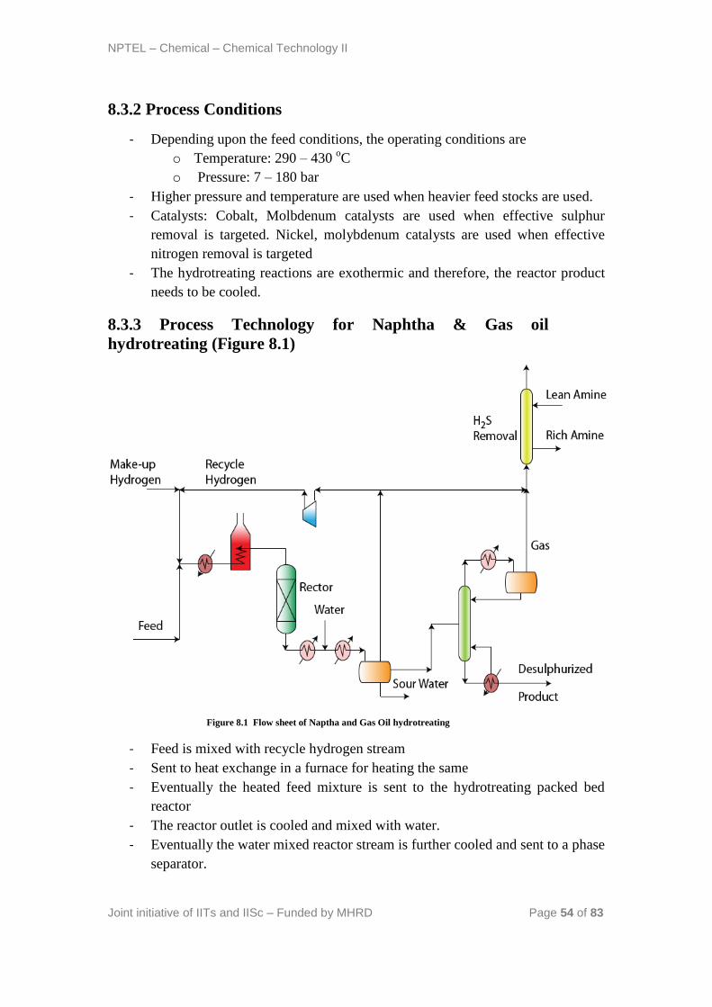
NPTEL – Chemical – Chemical Technology II
Joint initiative of IITs and IISc – Funded by MHRD Page 54 of 83
8.3.2 Process Conditions
- Depending upon the feed conditions, the operating conditions are
o Temperature: 290 – 430 oC
o Pressure: 7 – 180 bar
- Higher pressure and temperature are used when heavier feed stocks are used.
- Catalysts: Cobalt, Molbdenum catalysts are used when effective sulphur
removal is targeted. Nickel, molybdenum catalysts are used when effective
nitrogen removal is targeted
- The hydrotreating reactions are exothermic and therefore, the reactor product
needs to be cooled.
8.3.3 Process Technology for Naphtha & Gas oil
hydrotreating (Figure 8.1)
Figure 8.1 Flow sheet of Naptha and Gas Oil hydrotreating
- Feed is mixed with recycle hydrogen stream
- Sent to heat exchange in a furnace for heating the same
- Eventually the heated feed mixture is sent to the hydrotreating packed bed
reactor
- The reactor outlet is cooled and mixed with water.
- Eventually the water mixed reactor stream is further cooled and sent to a phase
separator.
NPTEL – Chemical – Chemical Technology II
Joint initiative of IITs and IISc – Funded by MHRD Page 55 of 83
- The phase separator splits the feed stream to three separate streams namely a
gas phase stream, an organic stream and an aqueous stream.
- The aqueous stream is rich of H2S and NH3 and will be sent out to a sour
water processing unit to recover H2S and NH3. The sour water processing unit
uses amine based absorption technology to recover H2S.
- The hydrotreated product is the organic stream enters a fractionator to stabilize
the hydrotreated product. Eventually the stabilizing fractionator produces a gas
stream from the partial condenser consisting of H2, C1-C4, H2S and NH3.
- The gas stream emanating from the phase separator consists of 60 – 90 % H2.
Majority of this stream is recycled using a compressor to mix with the make-
up hydrogen and enter the heat exchanger and furnaces. The other part of the
gas stream from the phase separator is purged to mix with the gas generated
from the fractionators and enter the absorption unit for H2S removal.
- When high sulphur feeds are used, H2S removal is carried out by placing an
additional absorber unit (with amine as an absorbent) to reduce higher
concentrations of H2S in the gas stream. In this case, a purge stream is
allowed to balance off the additional gas available as another by product from
the process.
8.3.4 Process technology for Residue hydrotreating
- Heavier hydrocarbon hydrotreating is carried out using guard reactors
- Guard reactors have catalysts with larger pore size first and then have
decreasing pore size along the reactor length.
- The guard reactors are followed with conventional packed bed reactors.
- This is due to the reason that heavier fractions could form coke and damage
the catalyst totally.
- Here, Nickel and Vanadium would stay back on the surface of the catalyst
- Except the guard reactors, the remaining flow sheet for residue hydrotreating
remains the same. Live steam is used in the fractionator and unstablized
naphtha is produced as one of the products in the residue hydrotreating
process.
8.4Hydrocracking
8.4.1 Process summary
- Cycle oils and coker distillates are the typical feedstocks
- High quality jet fuel and diesel production is targeted
- Overall reaction is exothermic
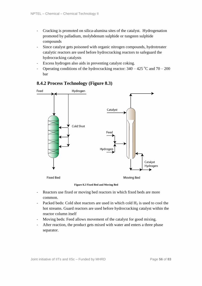
NPTEL – Chemical – Chemical Technology II
Joint initiative of IITs and IISc – Funded by MHRD Page 56 of 83
- Cracking is promoted on silica-alumina sites of the catalyst. Hydrogenation
promoted by palladium, molybdenum sulphide or tungsten sulphide
compounds
- Since catalyst gets poisoned with organic nitrogen compounds, hydrotreater
catalytic reactors are used before hydrocracking reactors to safeguard the
hydrocracking catalysts
- Excess hydrogen also aids in preventing catalyst coking.
- Operating conditions of the hydrocracking reactor: 340 – 425 oC and 70 – 200
bar
8.4.2 Process Technology (Figure 8.3)
Figure 8.2 Fixed Bed and Moving Bed
- Reactors use fixed or moving bed reactors in which fixed beds are more
common.
- Packed beds: Cold shot reactors are used in which cold H2 is used to cool the
hot streams. Guard reactors are used before hydrocracking catalyst within the
reactor column itself
- Moving beds: Feed allows movement of the catalyst for good mixing.
- After reaction, the product gets mixed with water and enters a three phase
separator.
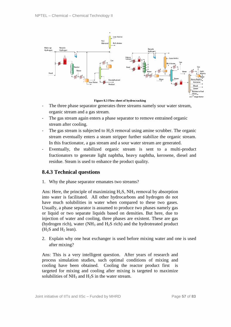
NPTEL – Chemical – Chemical Technology II
Joint initiative of IITs and IISc – Funded by MHRD Page 57 of 83
Figure 8.3 Flow sheet of hydrocracking
- The three phase separator generates three streams namely sour water stream,
organic stream and a gas stream.
- The gas stream again enters a phase separator to remove entrained organic
stream after cooling.
- The gas stream is subjected to H2S removal using amine scrubber. The organic
stream eventually enters a steam stripper further stabilize the organic stream.
In this fractionator, a gas stream and a sour water stream are generated.
- Eventually, the stabilized organic stream is sent to a multi-product
fractionators to generate light naphtha, heavy naphtha, kerosene, diesel and
residue. Steam is used to enhance the product quality.
8.4.3 Technical questions
1. Why the phase separator emanates two streams?
Ans: Here, the principle of maximizing H2S, NH3 removal by absorption
into water is facilitated. All other hydrocarbons and hydrogen do not
have much solubilities in water when compared to these two gases.
Usually, a phase separator is assumed to produce two phases namely gas
or liquid or two separate liquids based on densities. But here, due to
injection of water and cooling, three phases are existent. These are gas
(hydrogen rich), water (NH3 and H2S rich) and the hydrotreated product
(H2S and H2 lean).
2. Explain why one heat exchanger is used before mixing water and one is used
after mixing?
Ans: This is a very intelligent question. After years of research and
process simulation studies, such optimal conditions of mixing and
cooling have been obtained. Cooling the reactor product first is
targeted for mixing and cooling after mixing is targeted to maximize
solubilities of NH3 and H2S in the water stream.
NPTEL – Chemical – Chemical Technology II
Joint initiative of IITs and IISc – Funded by MHRD Page 58 of 83
3. Can we use steam instead of reboiler in the fractionator?
Ans: This is also an important question. Steam utilization instead of
reboilers is usually carried out for heavier hydrocarbons but not for the
light hydrocarbons such as naphtha and gas oil. This is to ensure that
lighter hydrocarbons are easily stripped from the heavier desulphurized
product and good product quality is obtained in the top and bottom
products of the fractionators.
4. Do we produce only gas when steam stripping facilitiated in the fractionators?
Ans: No, we produce three products from the partial condenser of the
fractionator. These are (a) sour water (steam condenses to form water),
unstabilized naphtha (this will again enter a stabilization unit) and a gas
stream.
5. Comment upon hydrogen requirements for various hydrotreatingfeedstocks?
Ans: Depending upon the feedstocks, hydrotreatingfeedstocks would be
fed with variant hydrogen requirements. For straight run naphtha, the
H2/Naphtha feed ratio is 1.4 – 5.7 Nm3/bbl of feed. For Gas oil, it is 5.5
– 16 Nm3/bbl feed. For kerosene, it is 2.7 – 11.2 Nm
3/bbl feed.
6. Why two phase separators are used for the reactor product in hydrocracking
flowsheet?
Ans: The first phase separator provides three streams based on its
temperature and pressure. However, when the temperature of the gas
stream is again reduced, again two phase streams would emanate. This
is due to the heat removal and due to this reason, adiabatic flash
conditions would exist and two streams would be generated. The
second phase separator could be optional as well, but it will affect the
catalyst performance. Long term performance studies along with
process simulation studies provide such minor changes in the process
flow sheet which are important to eventually phase out long term
profitability of the hydrocracking flow sheet.
References:
11. Gary J.H., Handwerk G.E., Petroleum Refining: Technology and Economics,
Taylor & Francis, 2005
12. Jones D.S.J., Elements of Petroleum Processing, John Wiley & Sons, 1995
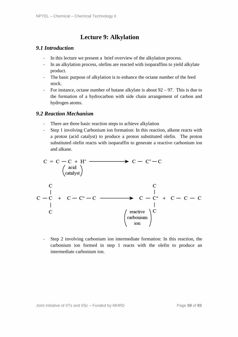
NPTEL – Chemical – Chemical Technology II
Joint initiative of IITs and IISc – Funded by MHRD Page 59 of 83
Lecture 9: Alkylation
9.1 Introduction
- In this lecture we present a brief overview of the alkylation process.
- In an alkylation process, olefins are reacted with isoparaffins to yield alkylate
product.
- The basic purpose of alkylation is to enhance the octane number of the feed
stock.
- For instance, octane number of butane alkylate is about 92 – 97. This is due to
the formation of a hydrocarbon with side chain arrangement of carbon and
hydrogen atoms.
9.2 Reaction Mechanism
- There are three basic reaction steps to achieve alkylation
- Step 1 involving Carbonium ion formation: In this reaction, alkene reacts with
a proton (acid catalyst) to produce a proton substituted olefin. The proton
substituted olefin reacts with isoparaffin to generate a reactive carbonium ion
and alkane.
- Step 2 involving carbonium ion intermediate formation: In this reaction, the
carbonium ion formed in step 1 reacts with the olefin to produce an
intermediate carbonium ion.
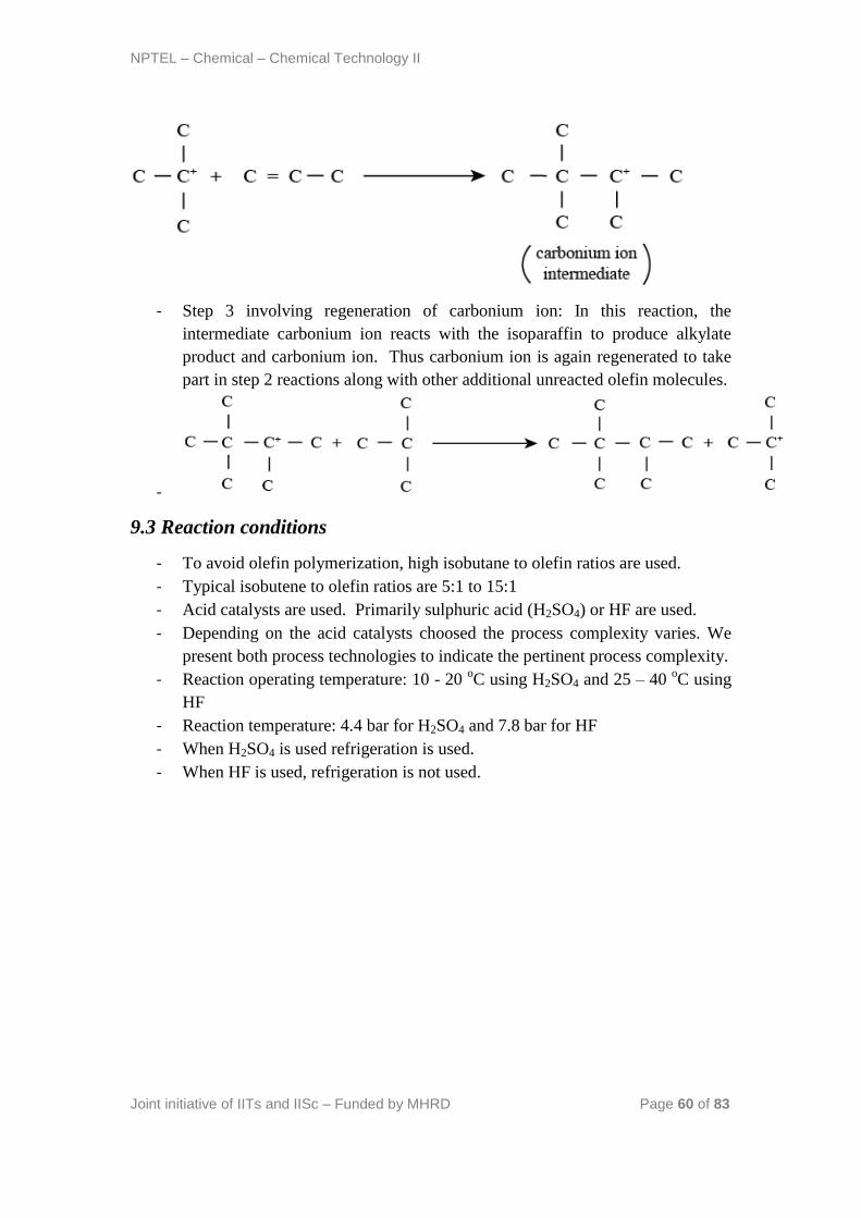
NPTEL – Chemical – Chemical Technology II
Joint initiative of IITs and IISc – Funded by MHRD Page 60 of 83
- Step 3 involving regeneration of carbonium ion: In this reaction, the
intermediate carbonium ion reacts with the isoparaffin to produce alkylate
product and carbonium ion. Thus carbonium ion is again regenerated to take
part in step 2 reactions along with other additional unreacted olefin molecules.
-
9.3 Reaction conditions
- To avoid olefin polymerization, high isobutane to olefin ratios are used.
- Typical isobutene to olefin ratios are 5:1 to 15:1
- Acid catalysts are used. Primarily sulphuric acid (H2SO4) or HF are used.
- Depending on the acid catalysts choosed the process complexity varies. We
present both process technologies to indicate the pertinent process complexity.
- Reaction operating temperature: 10 - 20 oC using H2SO4 and 25 – 40
oC using
HF
- Reaction temperature: 4.4 bar for H2SO4 and 7.8 bar for HF
- When H2SO4 is used refrigeration is used.
- When HF is used, refrigeration is not used.
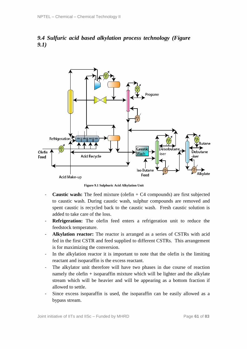
NPTEL – Chemical – Chemical Technology II
Joint initiative of IITs and IISc – Funded by MHRD Page 61 of 83
9.4 Sulfuric acid based alkylation process technology (Figure
9.1)
Figure 9.1 Sulphuric Acid Alkylation Unit
- Caustic wash: The feed mixture (olefin + C4 compounds) are first subjected
to caustic wash. During caustic wash, sulphur compounds are removed and
spent caustic is recycled back to the caustic wash. Fresh caustic solution is
added to take care of the loss.
- Refrigeration: The olefin feed enters a refrigeration unit to reduce the
feedstock temperature.
- Alkylation reactor: The reactor is arranged as a series of CSTRs with acid
fed in the first CSTR and feed supplied to different CSTRs. This arrangement
is for maximizing the conversion.
- In the alkylation reactor it is important to note that the olefin is the limiting
reactant and isoparaffin is the excess reactant.
- The alkylator unit therefore will have two phases in due course of reaction
namely the olefin + isoparaffin mixture which will be lighter and the alkylate
stream which will be heavier and will be appearing as a bottom fraction if
allowed to settle.
- Since excess isoparaffin is used, the isoparaffin can be easily allowed as a
bypass stream.
NPTEL – Chemical – Chemical Technology II
Joint initiative of IITs and IISc – Funded by MHRD Page 62 of 83
- Eventually, the alkylate product from the last reactor will be taken out as a
heavy stream.
- Thus, the alkylation reactor produces two streams. These are (a) isoparaffin
rich organic phase and (b) alkylate rich phase along with acid and isobutane
phases.
- These streams should be subjected to further purification.
- Phase separator: It so happens that the acid enters the organic rich stream
and will be subjected to phase separation by settling. Similarly, the
olefin/isoparaffin mixture will be also separated by gravity settling. Thus the
phase separator produces three streams namely (a) olefin + isoparaffin rich
phase (b) acid rich stream (c) alkylate rich stream.
- Olefin + Paraffin processing:The olefin + paraffin stream is first subjected to
compression followed by cooling. When this stream is subjected to throttling
and phase separation, then the olefin + paraffin rich stream will be generated.
The propane rich stream from this stream is generated as another stream in the
phase separator.
- Propane defractionator: The propane rich stream after cooling is fed to a
fractionator where propane is separated from the olefin+isoparaffin mixture.
The olefin+isoparaffin mixture is sent back to mix with the olefin feed.
- Caustic wash for alkylate rich stream: The caustic wash operation ensures
to completely eliminate acid concentration from the alkylate.
- Alkylate fractionation:The alkylate is fed to a distillation column that is
supplied with isobutane feed and alkylate feeds to produce isobutane as a top
product and alkylate + butane mixture as a bottom product.
- Debutanizer: The debutanizer separates butane and alkylate using the concept
of distillation
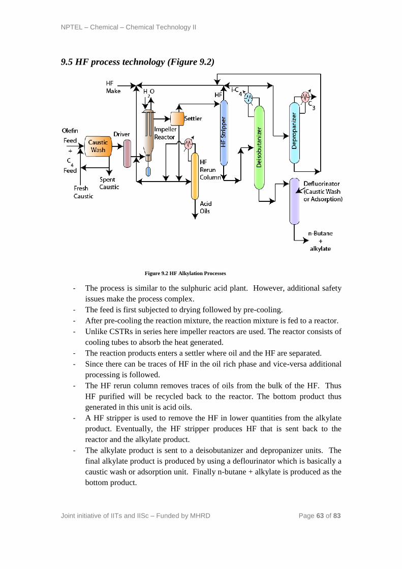
NPTEL – Chemical – Chemical Technology II
Joint initiative of IITs and IISc – Funded by MHRD Page 63 of 83
9.5 HF process technology (Figure 9.2)
Figure 9.2 HF Alkylation Processes
- The process is similar to the sulphuric acid plant. However, additional safety
issues make the process complex.
- The feed is first subjected to drying followed by pre-cooling.
- After pre-cooling the reaction mixture, the reaction mixture is fed to a reactor.
- Unlike CSTRs in series here impeller reactors are used. The reactor consists of
cooling tubes to absorb the heat generated.
- The reaction products enters a settler where oil and the HF are separated.
- Since there can be traces of HF in the oil rich phase and vice-versa additional
processing is followed.
- The HF rerun column removes traces of oils from the bulk of the HF. Thus
HF purified will be recycled back to the reactor. The bottom product thus
generated in this unit is acid oils.
- A HF stripper is used to remove the HF in lower quantities from the alkylate
product. Eventually, the HF stripper produces HF that is sent back to the
reactor and the alkylate product.
- The alkylate product is sent to a deisobutanizer and depropanizer units. The
final alkylate product is produced by using a deflourinator which is basically a
caustic wash or adsorption unit. Finally n-butane + alkylate is produced as the
bottom product.
NPTEL – Chemical – Chemical Technology II
Joint initiative of IITs and IISc – Funded by MHRD Page 64 of 83
9.6 Technical questions
1. Why isobutane is fed to the deisobutanizer unit in the sulphuric acid flow
sheet?
Ans: The isobutane feed consists of n-butane and it should be separated so
that the alkylation reactor is fed with only isobutane. Now, the issue is to
use a separate distillation column for separating isobutane feed into
isobutane and butane. This will incur additional costs. Therefore, instead of
two separate columns, both separations are carried out in the same
distillation column. Ofcourse, costs will be saved by this concept in
processing.
2. Explain how compression and cooling will enable the separation of
propane and olefin+isoparaffins mixture?
Ans: The separation of propane from isoparaffins and olefins is very
difficult due to close boiling points of these streams. Now, compression is
also required so as to avoid refrigeration system in the condenser of
propane. This is also due to the fact that higher pressures increasing boiling
point of the propane and enable the usage of cooling water in the condenser.
On the other hand, removing heat from the system will enable adiabatic
flash conditions which can be exploited to separate the propane and
olefin+isoparaffin mixture.This entire operation has significant research in
the field of thermodynamics and mass transfer subjects. Probably, good
number of simulation studies have finally yielded the flowsheet to obtain
such configurations.
3. What are the advantages of H2SO4 process when compared to the HF
process?
- Additonal equipment is not need in this process. This is not the case in HF
process where HF recovery or neutralization requires additional processes.
- HF can form a toxic vapour cloud therefore, safety parameters need to be more
effectively considered.
- Higher capital costs in HF process
- Good quality product is produced in sulphuric acid process but not the HF
process.
4. Why is deisobutanizer placed before the depropanizer?
Ans: Isobutane is used in excess. If propane is removed first then both the
columns have high flow rates. Since column costs are proportional to the
flow rates, deisobutanizer is placed before depropoanizer so that the
depropanizer can process less feed and hence have lower diameters and
cost.
NPTEL – Chemical – Chemical Technology II
Joint initiative of IITs and IISc – Funded by MHRD Page 65 of 83
5. What additional units are there in the HF process flow sheet when
compared to the sulphuric acid flow sheet?
a. Drier
b. Deflourinator
c. Safety instrumentation and accessories
References:
13. Gary J.H., Handwerk G.E., Petroleum Refining: Technology and Economics,
Taylor & Francis, 2005
14. Jones D.S.J., Elements of Petroleum Processing, John Wiley & Sons, 1995
NPTEL – Chemical – Chemical Technology II
Joint initiative of IITs and IISc – Funded by MHRD Page 66 of 83
Lecture 10: Visbreaking and Coking
10.1 Introduction
- In this lecture, we present two important processes that are used to upgrade the
residue product obtained from the vacuum distillation unit.
- Significant amounts of vacuum residue is obtained from various crude oils.
For instance Arabian heavy oil produces 23.2 vol% vacuum residue product.
- The residue consists of heavier hydrocarbons with molecular weights ranging
from 5000 – 10000.
- Thermal cracking is most preferable for the vacuum residue.
- The vacuum residue also consists of other metals such as vanadium and
nickel.
- Typically, vacuum residue is subjected to six different operations namely
o Vacuum residue desulphurization (VRDS)
o Residue fluid catalytic cracking (RFCC)
o Visbreaking
o Coking
o Deasphalting
o Gasification
- Amongst these, Viskbreaking and coking are prominent operations that exist
in many refineries and we restrict our discussion to these processes only.
10.2 Visbreaking
- In Visbreaking operation, a mild thermal cracking is carried out.
- Visbreaking produces Naphtha, Gasoil and a residue. The residue has lower
viscosity and pour point and hence can easily meet the requirements of the
fuel oil specifications in the fuel oil blending pool.
- Visbreaking basically breaks the long paraffinic side chains attached to
aromatic structures. Due to this the residue pour point and viscosities are
considerably reduced.
- Two classes of reactions occur during visbreaking
o Cracking of side chained aromatic compounds to produce short
chained aromatics and paraffins
o Cracking of large molecules to form light hydrocarbons
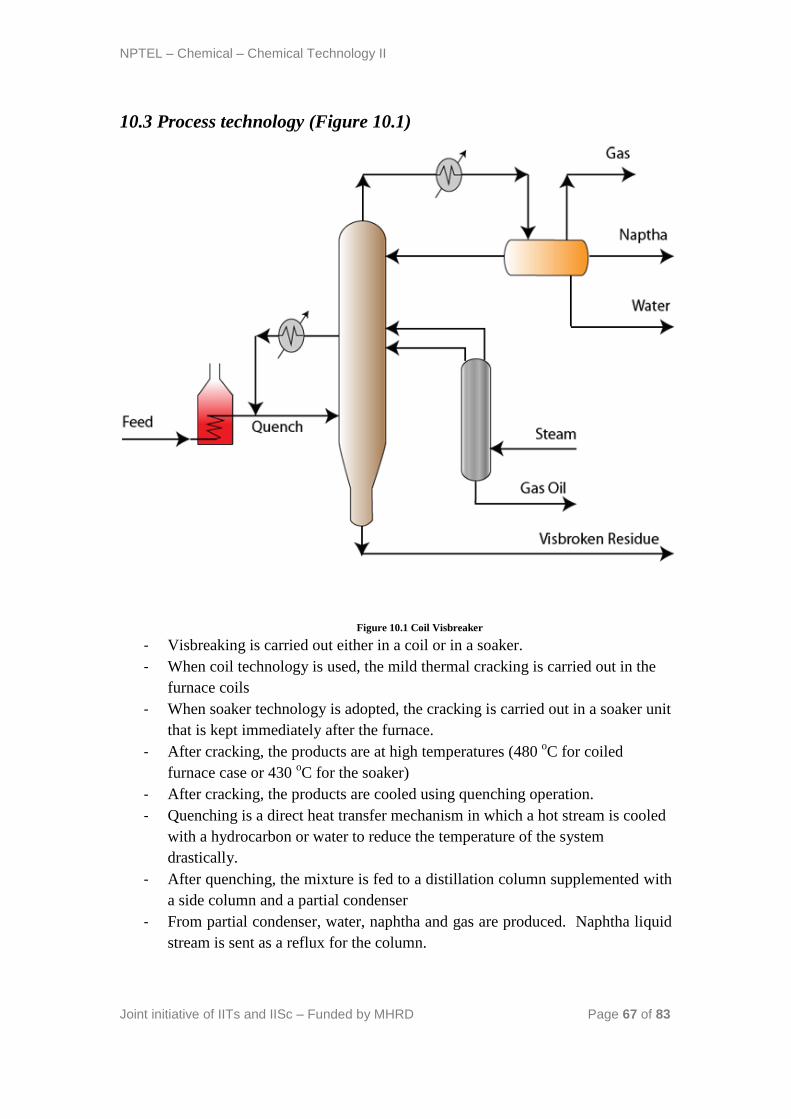
NPTEL – Chemical – Chemical Technology II
Joint initiative of IITs and IISc – Funded by MHRD Page 67 of 83
10.3 Process technology (Figure 10.1)
Figure 10.1 Coil Visbreaker
- Visbreaking is carried out either in a coil or in a soaker.
- When coil technology is used, the mild thermal cracking is carried out in the
furnace coils
- When soaker technology is adopted, the cracking is carried out in a soaker unit
that is kept immediately after the furnace.
- After cracking, the products are at high temperatures (480 oC for coiled
furnace case or 430 oC for the soaker)
- After cracking, the products are cooled using quenching operation.
- Quenching is a direct heat transfer mechanism in which a hot stream is cooled
with a hydrocarbon or water to reduce the temperature of the system
drastically.
- After quenching, the mixture is fed to a distillation column supplemented with
a side column and a partial condenser
- From partial condenser, water, naphtha and gas are produced. Naphtha liquid
stream is sent as a reflux for the column.
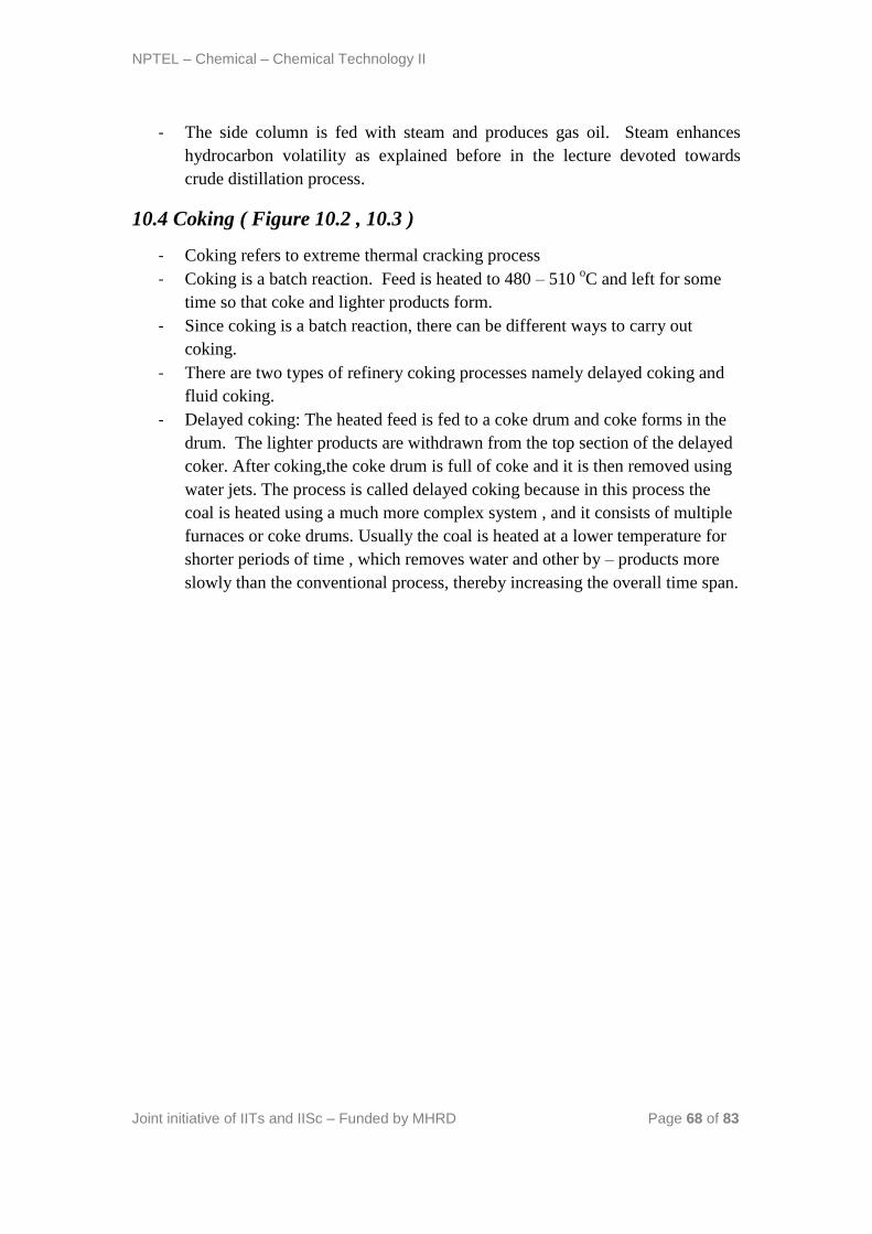
NPTEL – Chemical – Chemical Technology II
Joint initiative of IITs and IISc – Funded by MHRD Page 68 of 83
- The side column is fed with steam and produces gas oil. Steam enhances
hydrocarbon volatility as explained before in the lecture devoted towards
crude distillation process.
10.4 Coking ( Figure 10.2 , 10.3 )
- Coking refers to extreme thermal cracking process
- Coking is a batch reaction. Feed is heated to 480 – 510 oC and left for some
time so that coke and lighter products form.
- Since coking is a batch reaction, there can be different ways to carry out
coking.
- There are two types of refinery coking processes namely delayed coking and
fluid coking.
- Delayed coking: The heated feed is fed to a coke drum and coke forms in the
drum. The lighter products are withdrawn from the top section of the delayed
coker. After coking,the coke drum is full of coke and it is then removed using
water jets. The process is called delayed coking because in this process the
coal is heated using a much more complex system , and it consists of multiple
furnaces or coke drums. Usually the coal is heated at a lower temperature for
shorter periods of time , which removes water and other by – products more
slowly than the conventional process, thereby increasing the overall time span.
NPTEL – Chemical – Chemical Technology II
Joint initiative of IITs and IISc – Funded by MHRD Page 69 of 83
Figure 10.2 Delayed Coker
- Fluid coking: The heated feed is fed to a fluidized bed where coke particles
with finer particle sizes would aid fluidization. After coking, lighter products
are withdrawn as overhead vapour and coke thus formed is removed
continuously. The fluid coker also has an additional scrubber which will
remove heavier compounds from the vapors (if any) and send them back with
the feed stream. Here, the feed stream absorbs heavier hydrocarbons from the
vapors generated. This is required as it is difficult to keep heavier
hydrocarbons in the feed phase only due to pertinent high temperatures. The
coke after coking reaction is cold coke. Therefore, to generate hot coke, a
burner unit is used to heat the coke using exothermic CO2 reaction. The
offgases from the burner are sent to cyclones, scrubbing and then to the vent.
The hot coke thus obtained is recycled back to the fluidized bed or taken out
as a net coke product.

NPTEL – Chemical – Chemical Technology II
Joint initiative of IITs and IISc – Funded by MHRD Page 70 of 83
Figure 10.3 Fluid Coking
- The coker products are fed to a complex distillation column i.e., main column
supplemented with side columns. From the complex distillation column,
naphtha, water, light gas oil and heavy gas oil are obtained.
- Additional complexities in the distillation unit are
o Feed entering the distillation column but not the coker unit: This is to
facilitate the removal of light ends from the feed (if any) and don’t
subject them to cracking. This is also due to the reason that light ends
are valuable commodities and we don’t want to loose them to produce
cheap coke product. In this case, the bottom product from the
distillation column is fed to the furnace for pre-heating and subsequent
coking operation.
o Live steam in distillation: This is to facilitate easy removal of lighter
hydrocarbons in various sections.
o Circulatory reflux (Pump around units): This is to facilitate good
amount of liquid reflux in various sections of the main column. For
Further details, of the above two issues, please refer to the crude
distillation lecture notes.
NPTEL – Chemical – Chemical Technology II
Joint initiative of IITs and IISc – Funded by MHRD Page 71 of 83
10.5 Technical questions
1. Why thermal cracking is most preferable for vacuum residue than
catalytic cracking?
Ans: Since heavier compounds are present in the vacuum residue, they can
totally poison the catalyst with coke deposition. Therefore, thermal but not
catalytic cracking is preferred.
2. Provide technical insight for quenching?
Ans: Quenching is one of the oldest technique to control temperatures of a
stream without involving indirect heat transfer. The basic advantage of the
quenching is that if a cold fluid with similar chemical constitution is mixed,
then it reduces the temperature of the cold fluid and increases the
temperature of the quenching fluid. Quenching is also an instantaneous
operation which is not the case of indirect heat transfer. Also, in indirect
heat transfer, losses could be significant due to additional process resistance
for heat transfer. This is not the case in quenching where the hot fluid
directly comes in contact with the cold fluid. The basic disadvantage in
quenching is that if a cold fluid of different chemical constitution is used
then additional separation (downstream) is required. If that can be avoided,
quenching is an excellent operation.
3. Are there any heat integration opportunities existent for the visbreaking
operation?
Ans: No, the reason is that the vapour from the fractionators is a hot stream
and the quenching stream is also a hot stream. We need atleast one cold
stream and hot stream to enable heat integration.
4. Explain the reason behind recycling of intermediate process streams in
fluid coker?
Ans: An essential issue in fluidization is to maintain a uniform temperature
throughout the fluidized bed. To do so, partial recycle of intermediate
vapour streams is carried out so that uniform temperatures are maintained.
5. Do opportunities exist in coking operation for heat integration?
Ans: Yes, they exist very much. The hot products from the complex
distillation unit as well as the vapors generated from the coke drums are the
hot streams. The cold stream is the feed which is subjected to pre-heated.
Since we have a cold stream and good number of hot streams, we can have a
good heat integration opportunity in the coking operation.

NPTEL – Chemical – Chemical Technology II
Joint initiative of IITs and IISc – Funded by MHRD Page 72 of 83
6. What is flexicoking?
Ans: In flexi coking, coke is fed to a gasifier to react with air and steam.
Eventually, the coke produces hydrogen, CO, CO2, N2, H2O and H2S. The
gas thus obtained is used as a fuel gas in the refinery itself for various
furnace operations. Therefore, flexicoking refers to flexibly alter the coking
process to produce additionally gas using an extra gasification unit.
Flow sheets to Dekaji
1. Coil visbreaker
2. Fluid coking process
Delayed coker
References:
15. Gary J.H., Handwerk G.E., Petroleum Refining: Technology and Economics,
Taylor & Francis, 2005
16. Jones D.S.J., Elements of Petroleum Processing, John Wiley & Sons, 1995
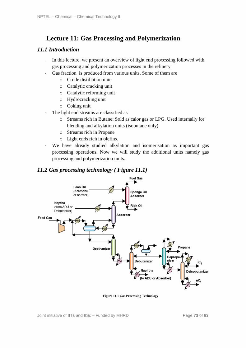
NPTEL – Chemical – Chemical Technology II
Joint initiative of IITs and IISc – Funded by MHRD Page 73 of 83
Lecture 11: Gas Processing and Polymerization
11.1 Introduction
- In this lecture, we present an overview of light end processing followed with
gas processing and polymerization processes in the refinery
- Gas fraction is produced from various units. Some of them are
o Crude distillation unit
o Catalytic cracking unit
o Catalytic reforming unit
o Hydrocracking unit
o Coking unit
- The light end streams are classified as
o Streams rich in Butane: Sold as calor gas or LPG. Used internally for
blending and alkylation units (isobutane only)
o Streams rich in Propane
o Light ends rich in olefins.
- We have already studied alkylation and isomerisation as important gas
processing operations. Now we will study the additional units namely gas
processing and polymerization units.
11.2 Gas processing technology ( Figure 11.1)
Figure 11.1 Gas Processing Technology
NPTEL – Chemical – Chemical Technology II
Joint initiative of IITs and IISc – Funded by MHRD Page 74 of 83
- The objective of gas processing is to produce ethane and methane.
- The produced ethane and methane is to serve later for fuel gas or hydrogen
production
- The gas processing section consists mainly of two different sections
- Absorption using Naphtha and kerosene:
o First, collected gases are compressed to be fed to an absorption.
o The purpose of naphtha is to absorb heavier hydrocarbons in the gas
fraction. These are C3s and C4s in the feed stream. To carry out
absorption, first the gases are cooled and fed to a phase separator to
facilitate early separation of lighter and heavier fractions.
o From the phase separator two streams emanate namely a gas stream
and a liquid stream.
o The gas stream is fed to an absorber unit where naphtha is used as a
solvent to absorb the left heavier hydrocarbons in the gas.
o The naphtha rich with hydrocarbons is fed to the phase separator so as
to stabilize the naphtha stream.
o The gas from the absorber is fed to a second absorber where lean oil
(such as kerosene) is used as a solvent to absorb any heavier
hydrocarbons other than the methane and hydrogen. Eventually, fuel
gas is produced as the gas product from this absorption. The other
product from the absorber is the rich oil stream
- Naphtha rich stream processing:
o The liquid product from the phase separator is fed to a deethanizer
which generates ethane rich stream as the top product. This stream is
recycled back to the gas processing unit i.e., mixing with the feed and
subjected to cooling followed by phase separator.
o The bottom product from deethanizer is naphtha rich stream with
butanes and propanes.
o This stream is subjected to fractionation using debutanizer,
depropanizer and deisobutanizer to obtain propane, isobutane and
naphtha. The stabilized naphtha can be used for absorption purposes.
11.3 Olefin Polymerization
- Olefin polymerization to yield polymer gasoline is primarily carried out to
obtain polymers with good octane numbers.
- The octane number of the polymer gasoline product is not greater than the
octane number of the products produced from reforming and alkylation.
Instead, comparatively poor quality product is obtained. But for the sake of
enhancing octane number polymerization is carried out.
NPTEL – Chemical – Chemical Technology II
Joint initiative of IITs and IISc – Funded by MHRD Page 75 of 83
- On the other hand, polymer gasoline has more vapour pressure than the
corresponding alkylation products. Therefore, in both ways, polymer
gasoline product quality is lower than that obtained from the alkylation unit.
- Typical feedstocks for polymerization process are C3 and C4 olefins that are
obtained from catalytic cracking
- The end product from polymerization reactor is a dimer or a trimer of the
olefins.
11.4 Reaction mechanism&Operating conditions
Reaction mechanism comprises of four basic steps
- Carbonium ion formation (Step 1): Here, olefin reacts with acid catalyst to
yield carbonium ion.
- Additon reaction (Step 2): Carbonium ion reacts with olefin to generate
intermediate carbonium ion
- Regeneration (Step 3): The intermediate carbonium ion converts to the dimer
and generates back the proton on the catalyst surface
- Isomerization (Step 4): Straight chain proton substituted olefins convert to
isomeric carbonium ions.
- Catalysts used: Acid catalysts (H2SO4) are used.
- Temperature: 150 – 220 oC are used. Too high temperatures give tar deposits.
- Pressure: 25 – 100 atms
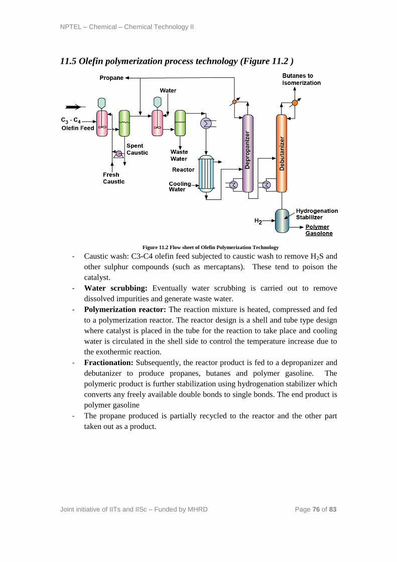
NPTEL – Chemical – Chemical Technology II
Joint initiative of IITs and IISc – Funded by MHRD Page 76 of 83
11.5 Olefin polymerization process technology (Figure 11.2 )
Figure 11.2 Flow sheet of Olefin Polymerization Technology
- Caustic wash: C3-C4 olefin feed subjected to caustic wash to remove H2S and
other sulphur compounds (such as mercaptans). These tend to poison the
catalyst.
- Water scrubbing: Eventually water scrubbing is carried out to remove
dissolved impurities and generate waste water.
- Polymerization reactor: The reaction mixture is heated, compressed and fed
to a polymerization reactor. The reactor design is a shell and tube type design
where catalyst is placed in the tube for the reaction to take place and cooling
water is circulated in the shell side to control the temperature increase due to
the exothermic reaction.
- Fractionation: Subsequently, the reactor product is fed to a depropanizer and
debutanizer to produce propanes, butanes and polymer gasoline. The
polymeric product is further stabilization using hydrogenation stabilizer which
converts any freely available double bonds to single bonds. The end product is
polymer gasoline
- The propane produced is partially recycled to the reactor and the other part
taken out as a product.
NPTEL – Chemical – Chemical Technology II
Joint initiative of IITs and IISc – Funded by MHRD Page 77 of 83
11.6 Technical questions
1. Why is the deethanizer top product recycled to the cooler followed with
phase separator?
Ans: The deethanizer top product consists of ethane rich stream but not a
pure product. Therefore, instead of further distillation of the fraction, it is
sent to the phase separator. This means that ethane is not produced as a
product here. This is also practised in the refinery. Also, there are refineries
that produce ethane as a product. It all depends on the subsequent operation
that the refinery plans with the ethane generated.
2. Why the sequence is followed to remove ethane, propane, butane and
isobutene?
Ans: This is an important question that one should understand. From a
mixture of ethane, propane, butane and isobutane in naphtha, the easiest to
separate is ethane followed with propane, butane and isobutane. Therefore,
isobutane separation is the toughest.
3. Why is naphtha rich with heavier hydrocarbons sent to the phase
separator?
Ans: The naphtha stream rich with heavier hydrocarbons is not a stream that
consists of only heavier hydrocarbons. It also consists of lighter
hydrocarbons. This is the problem we face always in chemical industry.
Textbooks always enable a student to understand two component
absorption, but in the real world we deal with multicomponent systems.
The basic problem in multicomponent process is that we cannot dictate the
absorption of a particular component only. For instance, when we absorb a
mixture of NH3 and CO2, we see that both NH3 and CO2 get absorbed. We
cannot dictate to the process to say that only NH3 gets absorbed. Therefore,
since it is possible that naphtha could absorb lighter hydrocarbons also due
to the existing absorption factors for various components. Henceforth, it is
important to note that naphtha rich with hydrocarbons needs to be stabilized.
This stabilization requires either stripping or any other operation. By
bringing in stripping, we are complicating of using another distillation unit
and once again energy requirements for that column. Instead of that, simply
the naphtha is fed to the phase separator to enable the stabilization of
naphtha in the phase separator itself.
NPTEL – Chemical – Chemical Technology II
Joint initiative of IITs and IISc – Funded by MHRD Page 78 of 83
4. What modification you can think in the polymerization reactor process
instead of using a shell and tube design?
Ans: Well, this is an important question. If we analyze the shell and tube
design, we want to achieve simultaneous cooling of the olefin stream in the
tube. Instead of cooling, we can also try cold shot technique or diluent in
the stream. When diluents is used, then the diluents or inert carrier needs to
be separated and its an additional task in the process. Therefore, the best
possibility is to target either a cold shot feed or a cold shot product with
recycle. Since conversions are low, doing cold shot with feed is not
beneficial. Therefore, cold shot product will be the optimal arrangement to
replace the shell and tube design. In that case, the product should be cooled
and send back to the reactor.
5. Can optionally propane be fed to the polymerization reactor?
Ans: Few process flowsheets involve propane as well fed to the
polymerization reactor, but conversions are expected to significantly low for
propane. Therefore, as such much gain will not be there by feeding propane
to the polymerization reactor.
References :
Gary J.H., Handwerk G.E., Petroleum Refining: Technology and
Economics, Taylor & Francis, 2005
Jones D.S.J., Elements of Petroleum Processing, John Wiley & Sons, 1995
Ullmann F., Encyclopedia of Industrial Chemistry, Wiley – VCH, 1999-
2012
Kirk R. E., Othmer D. F., Encyclopedia of Chemical Technology, John
Wiley and Sons, 1999-2012
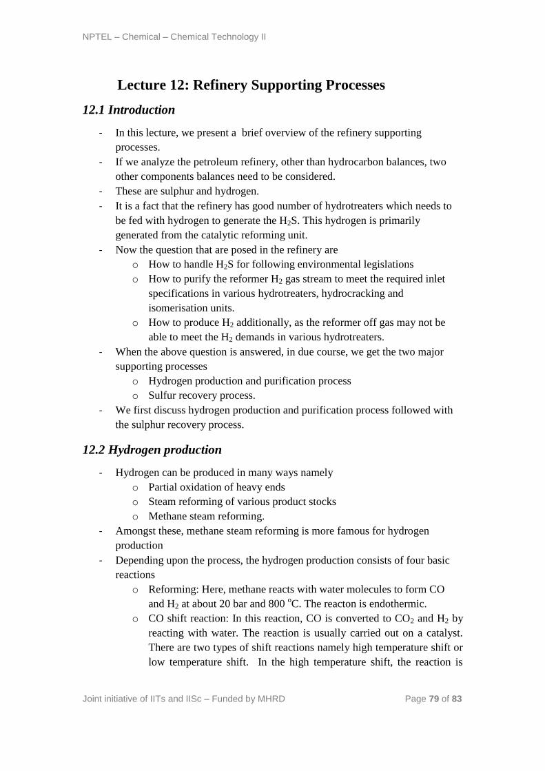
NPTEL – Chemical – Chemical Technology II
Joint initiative of IITs and IISc – Funded by MHRD Page 79 of 83
Lecture 12: Refinery Supporting Processes
12.1 Introduction
- In this lecture, we present a brief overview of the refinery supporting
processes.
- If we analyze the petroleum refinery, other than hydrocarbon balances, two
other components balances need to be considered.
- These are sulphur and hydrogen.
- It is a fact that the refinery has good number of hydrotreaters which needs to
be fed with hydrogen to generate the H2S. This hydrogen is primarily
generated from the catalytic reforming unit.
- Now the question that are posed in the refinery are
o How to handle H2S for following environmental legislations
o How to purify the reformer H2 gas stream to meet the required inlet
specifications in various hydrotreaters, hydrocracking and
isomerisation units.
o How to produce H2 additionally, as the reformer off gas may not be
able to meet the H2 demands in various hydrotreaters.
- When the above question is answered, in due course, we get the two major
supporting processes
o Hydrogen production and purification process
o Sulfur recovery process.
- We first discuss hydrogen production and purification process followed with
the sulphur recovery process.
12.2 Hydrogen production
- Hydrogen can be produced in many ways namely
o Partial oxidation of heavy ends
o Steam reforming of various product stocks
o Methane steam reforming.
- Amongst these, methane steam reforming is more famous for hydrogen
production
- Depending upon the process, the hydrogen production consists of four basic
reactions
o Reforming: Here, methane reacts with water molecules to form CO
and H2 at about 20 bar and 800 oC. The reacton is endothermic.
o CO shift reaction: In this reaction, CO is converted to CO2 and H2 by
reacting with water. The reaction is usually carried out on a catalyst.
There are two types of shift reactions namely high temperature shift or
low temperature shift. In the high temperature shift, the reaction is

NPTEL – Chemical – Chemical Technology II
Joint initiative of IITs and IISc – Funded by MHRD Page 80 of 83
carried out on iron oxide or chromia catalyst at about 350 – 550 oC. In
the low temperature shift, the reaction is carried out at 200 – 250 oC
using copper or zinc oxide on alumina.
o Gas purification: The CO2 is separated by passing the product gases
through amine scrubber
o Methanation: The remaining CO2 and CO are converted back to
methane using nickel-alumina catalyst in a reversible reaction scheme
at 400 oC.
12.3 Hydrogen production technology ( Figure 12.1 )
Figure 12.1 Flow sheet of Hydrogen Production Technology
- Feed purification: Feed pretreated to remove sulphur and halogens traces.
H2S is removed using zinc oxide catalysts. Organic sulphur removed by
hydrotreating and H2S removal from the feed. Halogens are removed using
adsorption technique.
- Furnace reactor: The methane steam reforming reaction occurs in a furnace
which is fed with the hydrocarbons mixed with steam. The steam to carbon
ratio varies and is about 2.5 – 3.5. The furnace reactor consists of reactor tubes
packed in the furnace chamber. The reactor tubes consist of the nickel oxide
catalyst for carrying out the reaction.
- Shift reactors: The furnace reactor product is sent to both high temperature
and low temperature shift reactors. It is interesting to note that these reactors
operate at low temperatures. Therefore, cooling is carried out for the furnace
reactor product and steam is generated. Similarly, steam is generated after the
high temperature shift reactor also.
- Absorber stripper: The absorber stripper is used for CO2 removal of the
product emanating from the low temperature shift reactor.
- Methanation reactor: Here, traces of the CO2 and CO are converted to CH4
and H2O using nickel catalyst and reversible reaction scheme. The product
from methanation reaction consists of 97 % H2.
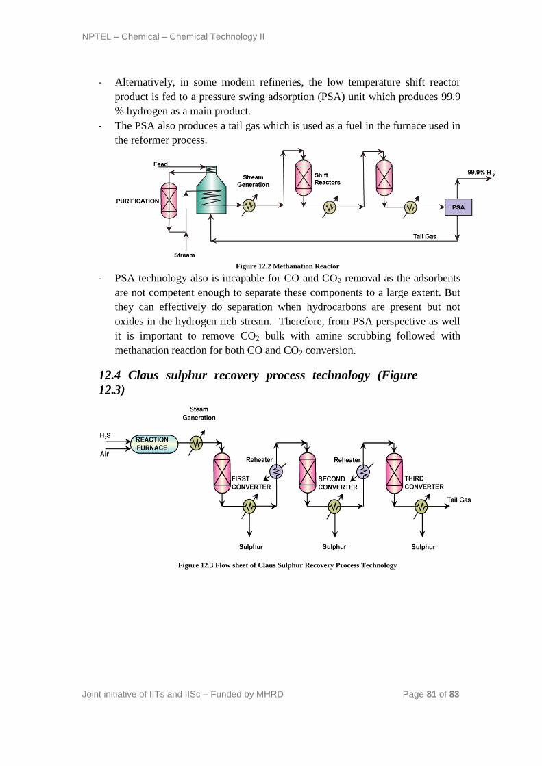
NPTEL – Chemical – Chemical Technology II
Joint initiative of IITs and IISc – Funded by MHRD Page 81 of 83
- Alternatively, in some modern refineries, the low temperature shift reactor
product is fed to a pressure swing adsorption (PSA) unit which produces 99.9
% hydrogen as a main product.
- The PSA also produces a tail gas which is used as a fuel in the furnace used in
the reformer process.
Figure 12.2 Methanation Reactor
- PSA technology also is incapable for CO and CO2 removal as the adsorbents
are not competent enough to separate these components to a large extent. But
they can effectively do separation when hydrocarbons are present but not
oxides in the hydrogen rich stream. Therefore, from PSA perspective as well
it is important to remove CO2 bulk with amine scrubbing followed with
methanation reaction for both CO and CO2 conversion.
12.4 Claus sulphur recovery process technology (Figure
12.3)
Figure 12.3 Flow sheet of Claus Sulphur Recovery Process Technology

NPTEL – Chemical – Chemical Technology II
Joint initiative of IITs and IISc – Funded by MHRD Page 82 of 83
- In a furnace reactor, H2S is partially oxided with air to produce water and SO2.
The reaction is highly exothermic. Therefore, steam is generated using the
products from the furnace reactor.
- The remaining H2S is then sent to a converter at about 250 oC to allow the
reaction between H2S and SO2 and produce Sulfur and water. The emanating
product is at 290 oC
- The second reactor (H2S to SO2) is having severe equilibrium limitations.
Therefore, it is sent to two to three reactors for maximizing conversion.
- After each converter, the product stream is cooled and sent to another reactor.
Subsequently, Sulphur is removed as a product from the coolers.
- Finally tail gas is obtained from the last converter which consists of unreacted
H2S, N2 and O2.
- The tail gas requires treatment as well. This is because the gas consists of
components such as H2S, CS2 etc. The tail gas is fed with air to another burner
and converter that converts sulphur compounds to H2S.The H2S thus generated
is separated using amine scrubbers. The H2S thus recovered is sent as a
recycle stream to the partial oxidation reactor.
12.5 Technical questions
1. How good is conversion in the steam methane reforming reaction?
Ans: By maintaining good process conditions, the conversion of the
methane steam reforming reaction can be achieved to about 60 – 80 % in a
single furnace reactor. Therefore, a single furnace reactor is sufficient to
achieve the desired conversion.
2. Why methanation cannot be avoided in the hydrogen production process?
Ans: The trace gases CO and CO2 are reactive towards the catalysts due to
the presence of oxygen molecule. Therefore, H2 sent to various other units
should be bereft of the CO and CO2 which can poison the catalyst due to the
reactive oxygen molecule.
3. Why CO2 bulk removal is targeted in the hydrogen production process?
Ans: CO2 bulk production if avoided will affect the product quality. The
methanation catalyst is not competent to fully convert CO2 back to methane
due to the reversibility of the reaction. Therefore, CO2 removal is required.
4. What oppurtunites exist for heat integration in the hydrogen production
process?
Ans: The feed to the process needs pre-heating therefore, is a cold steam.
Now this stream can be integrated with the furnace itself where the
combustion gases can be used to pre-heat the stream. Other than this the
NPTEL – Chemical – Chemical Technology II
Joint initiative of IITs and IISc – Funded by MHRD Page 83 of 83
furnace product, high and low temperature shift reactor products are also
available. The choice of heat integration and steam generation at various
sites in the process is a complex optimization problem and has to be
addressed by solving separate problems to finally arrive at the one optimal
solution. Mostly, the furnace combustion gases will be integrated for
energy recovery with the feed stream and steam generation is effected from
the high and low temperature shift reactors.
5. Explain how using three reactors in series will enhance equilibrium
conversion of the second conversion reaction i.e, H2S to S in Claus
process?
Ans: Equilibrium conversion is a function of temperature and pressure.
There are two types of equilibrium reactions namely exothermic and
endothermic reactions. For exothermic reactions, the conversion increases
with decreasing temperature. Therefore, after first converter, the product is
cooled and sulphur is also removed. The reduction in temperature and
elimination of sulphur moves the process conditions to a shift equilibrium to
the right hand side. Therefore, series of chemical reactors followed with
product cooling will enhance equilibrium conversion. By the by, the same
concept is also used in hot and cold shot reactors. The only difference
between this arrangement and the shot reactor arrangement is that there
direct heat transfer by quenching or heating is allowed where as in the
shown flow sheet, indirect heat transfer is facilitated only.
6. Why burner and converter are required in the tail gas processing unit?
Ans: The burner enhances the temperature of the stream and produce H2.
The produced H2 reacts with sulphur compounds to thereby produce H2S.
References:
Gary J.H., Handwerk G.E., Petroleum Refining: Technology and
Economics, Taylor & Francis, 2005
Jones D.S.J., Elements of Petroleum Processing, John Wiley & Sons, 1995