Embed Size (px)
Citation preview

Lic.(Tech.) Marko Luoma (1/58)
S-38.3191 Verkkopalvelujen tuotantoS-38.3191 Network Service Provisioning
Lecture 2: Conventional L2 Network Technologies

Lic.(Tech.) Marko Luoma (2/58)
L2 Technologies• Link layer technologies are used to build a point-to-point connection for
network layer protocols e.g. IP– Depends on
• Span of the network– LAN/MAN/WAN
• History of the network– Pure data network– Originally voice network
• Age of the network
Dark Fiber
Coloured FiberCWDM
SDH
ATM
Ethernet
IP
Lic.(Tech.) Marko Luoma (3/58)
L2 Technologies• Overall trend has been fluctuating from a low network stack to ones with very
many protocols on top of each other to back one with very low stack– Low stack:
• Efficient, coarse, rigid– High stack
• Accurate, flexible
Lic.(Tech.) Marko Luoma (4/58)
Transmission Systems• LAN technologies scale for LANs and campuses
– No transmission systems• Low controllability over resources
• For MANs and WANs you need transmission systems– Modern transmission systems use LAN interfaces for user side– Legacy transmission systems use IP and serial interfaces for user side

Lic.(Tech.) Marko Luoma (5/58)
Speed vs Distance• Transmission speed and distance without repeaters tend to be inversely
proportional• 1Gbps Ethernet -> 80-150km in SM-fiber with ZX-transmitter• 10Gbps Ethernet -> 10-40km in SM-fiber with ZX-transmitter
• How to gain maximal throughput with a minimal cost– Balance between cost and sensitivity of transmitters and receivers
• Adding repeaters lowers the sensitivity demand -> lowers the price -> adds device -> increases the price
– TCO

Lic.(Tech.) Marko Luoma (6/58)
Technologies• High bandwidth requirements• Transmission speeds are increasing
with a constant rate– 1995: 155Mbps (SDH/ATM)– 2000: 2.4Gps (SDH)– 2004: 10 Gbps (SDH/Ethernet)– 2000-2004 wavelength
technologies brought a new means to increase capacity• DWDM• CWDM
• Frame based multiplexing– Irrespective of low layer
functionality• Fiber/Radio
– Options today are• GMPLS• SDH• ATM• Ethernet• GFP• RPR
Lic.(Tech.) Marko Luoma (7/58)
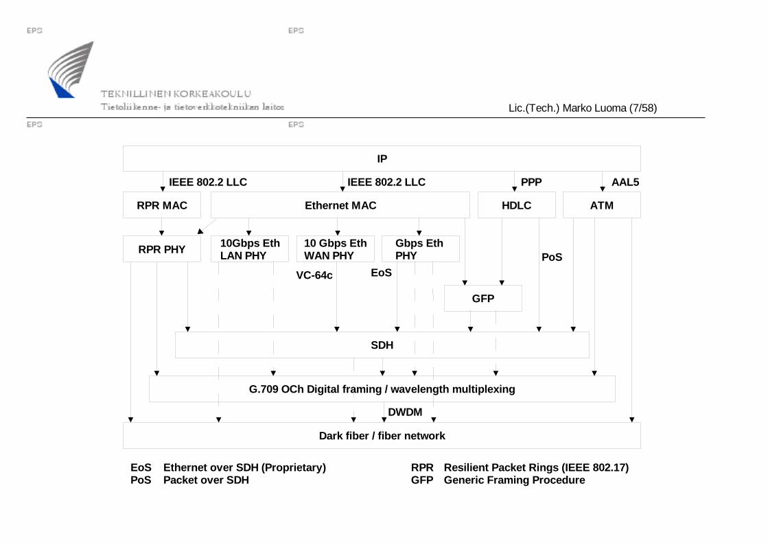
Dark fiber / fiber network
G.709 OCh Digital framing / wavelength multiplexing
SDH
GFP
RPR PHY 10Gbps EthLAN PHY
10 Gbps EthWAN PHY
Gbps Eth PHY
RPR MAC Ethernet MAC HDLC ATM
IP
AAL5PPPIEEE 802.2 LLCIEEE 802.2 LLC
PoSEoSVC-64c
DWDM
EoS Ethernet over SDH (Proprietary)PoS Packet over SDH
RPR Resilient Packet Rings (IEEE 802.17)GFP Generic Framing Procedure

Lic.(Tech.) Marko Luoma (8/58)
Fiber communication
WidebandMultimode
WidebandSinglemode
800 900 1000 1100 1200 1300 1400 1500 1600
0.2 dB/Km
0.5 dB/Km
2.0 dB/Km Fibre Attenuation Curve
λ / nm
E-band1360-1460
CWDM S-band1460-1530
DWDM
C-band1530-1565
DWDM/CWDM
L-band1565-1625
DWDM
• Fiber optics offers wide spectrum of which only narrow part is used by conventional wideband fiber transmitters

Lic.(Tech.) Marko Luoma (9/58)
Modern fiber communication• The goal is to push the limits of wideband fiber communications
– Wideband transmitters are expensive and electrical part with high speed is error prone• Multiple narrowband transmitters achieve same performance on
lower cost and lower error margin– To achieve longer transmission distances
• Lower attenuation of lower frequencies serves this goal– Narrow transmission window in C-band
» Narrow spacing of transmission channels

Lic.(Tech.) Marko Luoma (10/58)
Modern fiber communication• Packing of several channels into a single media causes multiple problems
related to interferences– Not just within fiber but also between channels
• How to inject multiple closely spaced signals into a fiber• How to detect them in receiver• How to control their defects caused by
– Dispersion– Attenuation
Lic.(Tech.) Marko Luoma (11/58)
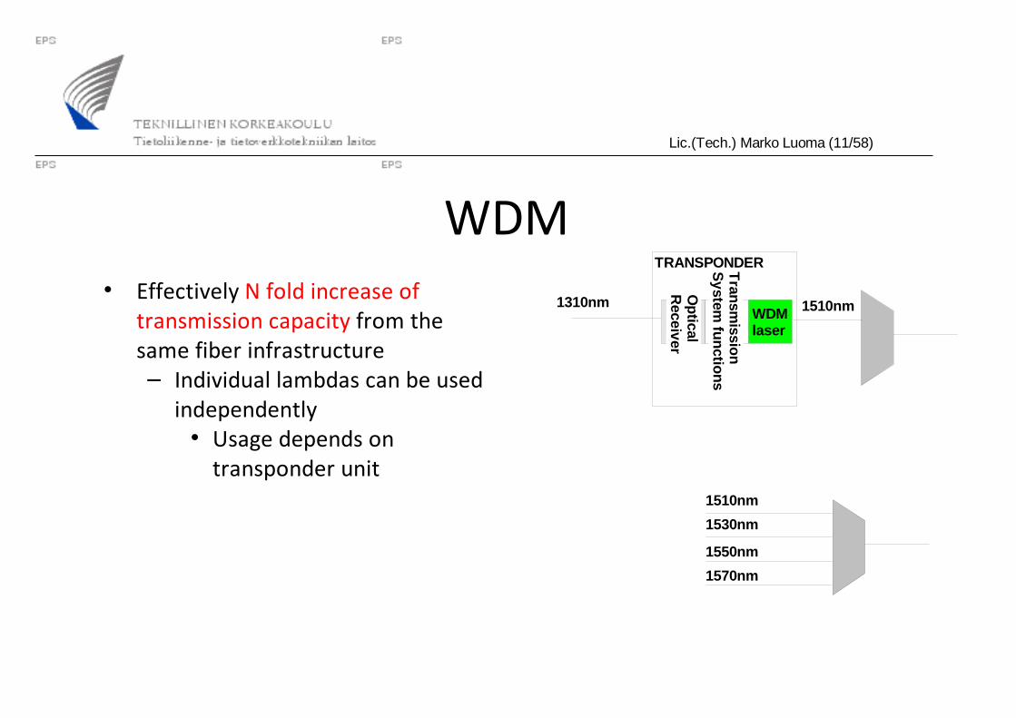
WDM• Effectively N fold increase of
transmission capacity from the same fiber infrastructure– Individual lambdas can be used
independently• Usage depends on
transponder unit
WDMlaser
Tran
smissio
nS
ystem fu
nctio
ns
Op
ticalR
eceiver
1310nm 1510nm
1510nm
TRANSPONDER
1530nm
1550nm
1570nm

Lic.(Tech.) Marko Luoma (12/58)
WDM• Two operative versions
– CWDM – Coarse Wavelength Division Multiplexing• Normally: 8 channels between (1470 - 1610nm / 20nm steps)• G.694.2: 18 channels between (1271 – 1611nm / 20nm steps)
– DWDM – Dense Wavelength Division Multiplexing• ITU Grid (100 Ghz resolution around 193.1Thz/1552.52nm)
– Sub grids with resolutions of 12.5/25/50GHz– Super grids with multiples of 100GHz
• https://www.ntt-review.jp/archive/ntttechnical.php?contents=ntr200709gls.pdf&mode=show_pdf

Lic.(Tech.) Marko Luoma (13/58)
WDM• DWDM
– Narrow channel spacing• Components need to be
compensated for temperature effects– Expensive
– More channels to choose from• nonlinearities of fibers can
be avoided by selecting proper wavelengths
• CWDM– Wide channel spacing
• Component requirements are looser– Cheaper lasers and
receivers– Less channels
• Not suitable for long-haul networks
• Suitable for MANs

Lic.(Tech.) Marko Luoma (14/58)
WDM• Can be used as link or network technology
– Link technology• Multiplexers at the ends of the links
– Network technology• Optical switching components
– Optical delay lines– Wavelength conversion– Photonic switching
• Collision free routing• Crosstalk issues
Lic.(Tech.) Marko Luoma (15/58)
WDM• Pros:
– Protocol independent– Virtual fiber– Multiplexing different traffic through different wavelengths
• Cons: – Depending on system pay as you go may not be possible
• The number of required channels need to be estimated for the lifetime of systems– Filters are designed for certain amount of wavelengths and
spacing
Lic.(Tech.) Marko Luoma (16/58)
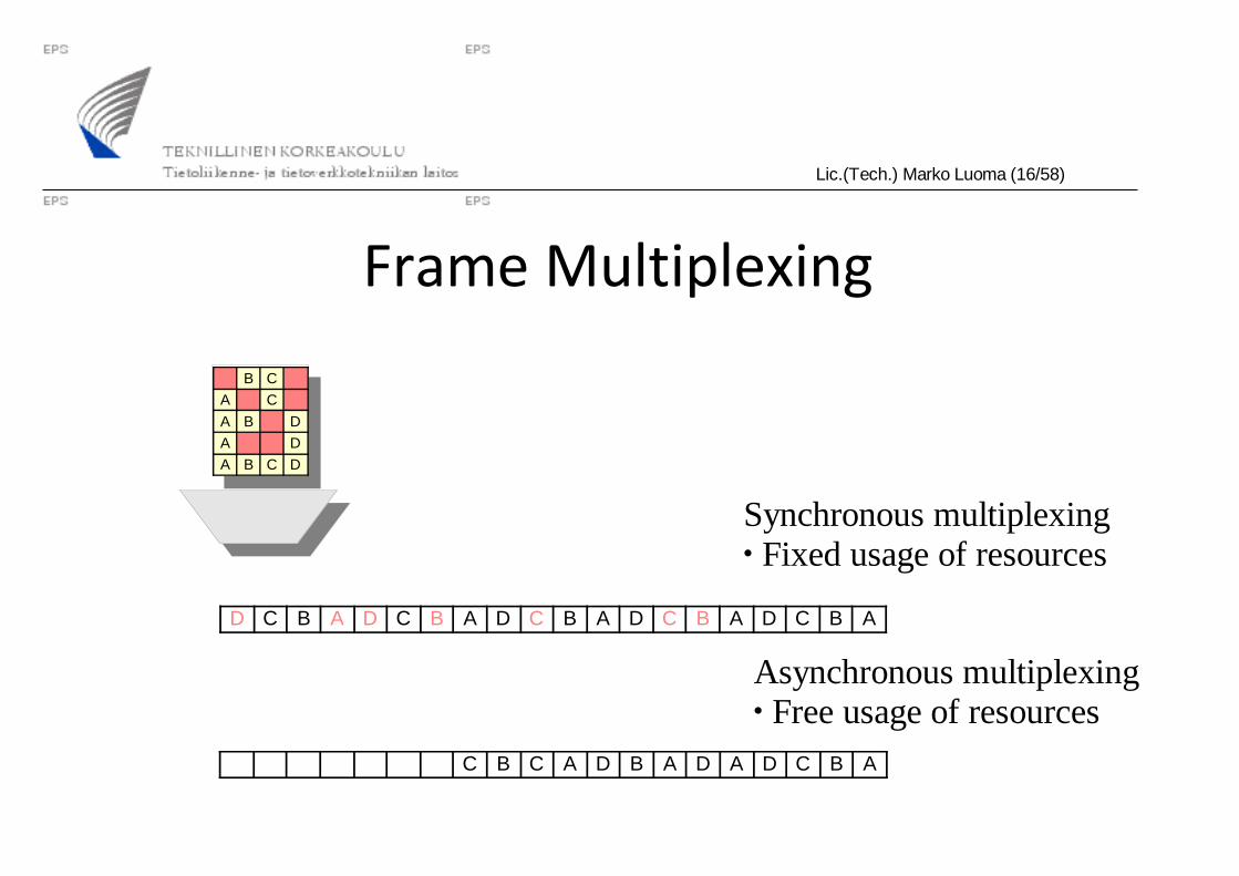
Synchronous multiplexing• Fixed usage of resources
Asynchronous multiplexing• Free usage of resources
Frame Multiplexing
B C
A C
A B D
A D
A B C D
D C B A D C B A D C B A D C B A D C B A
C B C A D B A D A D C B A
Lic.(Tech.) Marko Luoma (17/58)
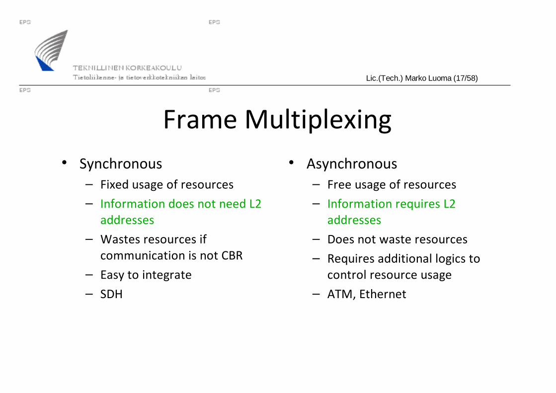
Frame Multiplexing• Synchronous
– Fixed usage of resources– Information does not need L2
addresses– Wastes resources if
communication is not CBR– Easy to integrate– SDH
• Asynchronous– Free usage of resources– Information requires L2
addresses– Does not waste resources– Requires additional logics to
control resource usage– ATM, Ethernet
Lic.(Tech.) Marko Luoma (18/58)
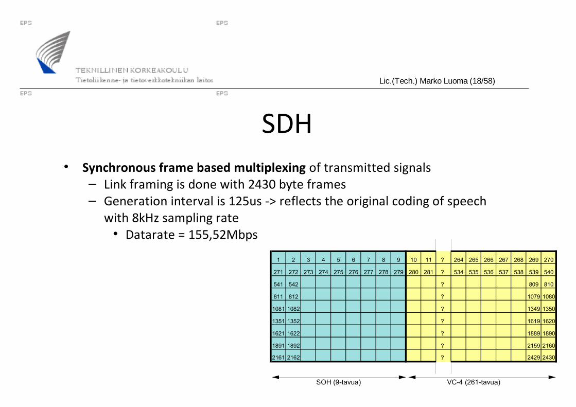
SDH• Synchronous frame based multiplexing of transmitted signals
– Link framing is done with 2430 byte frames– Generation interval is 125us -> reflects the original coding of speech
with 8kHz sampling rate• Datarate = 155,52Mbps
1 2 3 4 5 6 7 8 9 10 11 ? 264 265 266 267 268 269 270
271 272 273 274 275 276 277 278 279 280 281 ? 534 535 536 537 538 539 540
541 542 ? 809 810
811 812 ? 1079 1080
1081 1082 ? 1349 1350
1351 1352 ? 1619 1620
1621 1622 ? 1889 1890
1891 1892 ? 2159 2160
2161 2162 ? 2429 2430
SOH (9-tavua) VC-4 (261-tavua)
Lic.(Tech.) Marko Luoma (19/58)
POH
Content
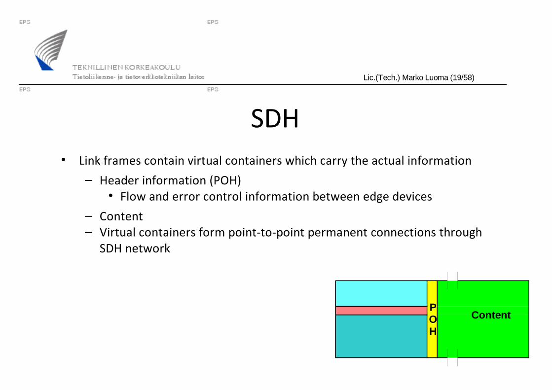
SDH• Link frames contain virtual containers which carry the actual information
– Header information (POH)• Flow and error control information between edge devices
– Content– Virtual containers form point-to-point permanent connections through
SDH network
Lic.(Tech.) Marko Luoma (20/58)
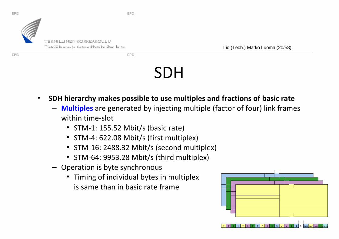
SDH• SDH hierarchy makes possible to use multiples and fractions of basic rate
– Multiples are generated by injecting multiple (factor of four) link frames within time-slot• STM-1: 155.52 Mbit/s (basic rate)• STM-4: 622.08 Mbit/s (first multiplex)• STM-16: 2488.32 Mbit/s (second multiplex)• STM-64: 9953.28 Mbit/s (third multiplex)
– Operation is byte synchronous• Timing of individual bytes in multiplex
is same than in basic rate frame
1 1 1 1 2 2 2 2 3 3 3 3 4 4 4 4 ? 2429 2430 2430 2430 2430

Lic.(Tech.) Marko Luoma (21/58)
SDH• Fractions are generated by multiplexing different streams of content into
individual frame– Several virtual containers destined to same or different points in network
– Multiplexing is donewith byte interleaving
TUG-2
STM-N AUG AU-4 VC-4 C-4
TUG-3 TU-3 VC-3 C-3
TU-2 VC-2 C-2
TU-12 VC-12 C-12
140M
45M
34M
6M
2M
Osoittimien käsittely
Multipleksaus
Mapitus
Vaiheistus
*N
*3
*7
*3
Lic.(Tech.) Marko Luoma (22/58)
SDH• SDH supports also concatenation of resources
– Old version – strict mode• Clear channel operation (small 'c' after the virtual container type)• All VC:s in different frames form a single bit stream• Not feasible in SDH networks• Feasible if SDH is used as a point to point link technology
– New version – flexible mode• Concatenation is used only in edge devices
– Supports SDH networks– Concatenated VC:s need not be with same speeds
» Even over different fibers

Lic.(Tech.) Marko Luoma (23/58)
SDH• IP can not be used directly with SDH
– Packet over Sonet (PoS) is method for delivering IP packets in SDH• Additional framing
– IP packet into PPP-packet– PPP packet into HDLC frame– HDLC frame into SDH
virtual container
IP packet
VC-x dataHEADER
HDLC-DataAddress(0xFF)
Control(0x03)
PPP-DataProtocol
N x HDLC frame
Padding
FCS(CRC-32)0x7E 0x7E
Lic.(Tech.) Marko Luoma (24/58)
SDH• Pros:
– Optimized for TDM services (large income from leased line services)– Fully compatible with metro ring networks (SDH ADM rings)– Reliable and fast failure recovery (roughly 50ms with APS)– Price of SDH continuously coming down
• Cons:– Not cost effective for burst data traffic
• Capacity in SDH network can only be allocated on multiples of 2Mbps– No multiple QoSs for different service charges– Expensive interfaces at routers
Lic.(Tech.) Marko Luoma (25/58)
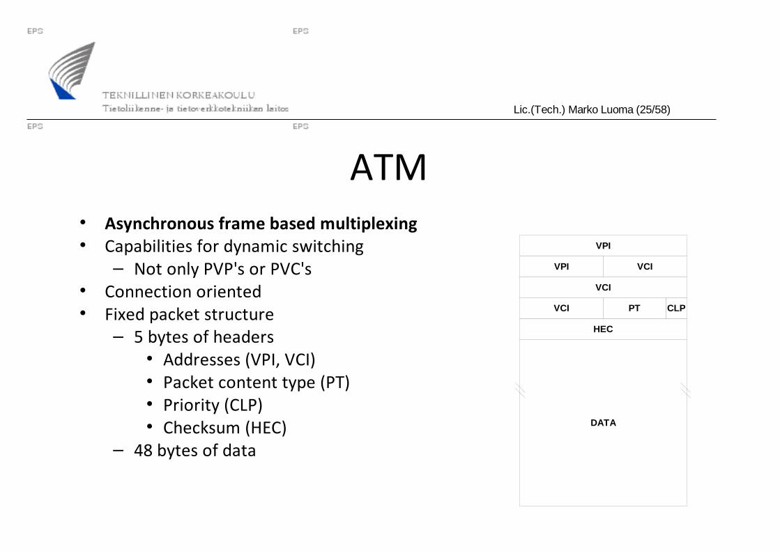
ATM• Asynchronous frame based multiplexing• Capabilities for dynamic switching
– Not only PVP's or PVC's• Connection oriented• Fixed packet structure
– 5 bytes of headers• Addresses (VPI, VCI)• Packet content type (PT)• Priority (CLP)• Checksum (HEC)
– 48 bytes of data
HEC
CLP
VCI
VCI
VPI
VPI
PTVCI
DATA
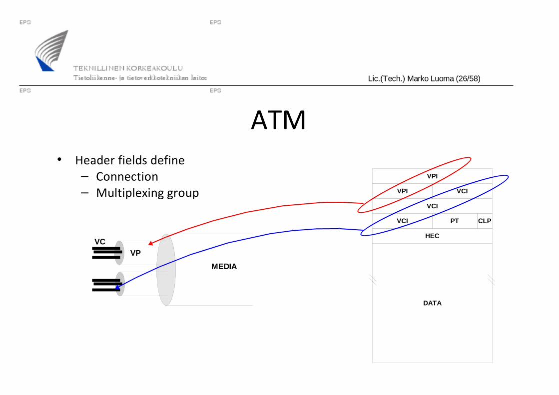
Lic.(Tech.) Marko Luoma (26/58)
ATM• Header fields define
– Connection– Multiplexing group
MEDIA
VPVC
HEC
CLP
VCI
VCI
VPI
VPI
PTVCI
DATA

Lic.(Tech.) Marko Luoma (27/58)
ATM• Can be used
– As is over the transmission media• Assumes low bit error ratio from the media
– Over any other L2 protocol• Benefits from the error control of L2 media
• Why sensitivity to BER– Packet has not markers
• Delineation is accomplished through state-machine which goes through packet bit by bit and looks header checksum matches– Sensitive to errors if high BER
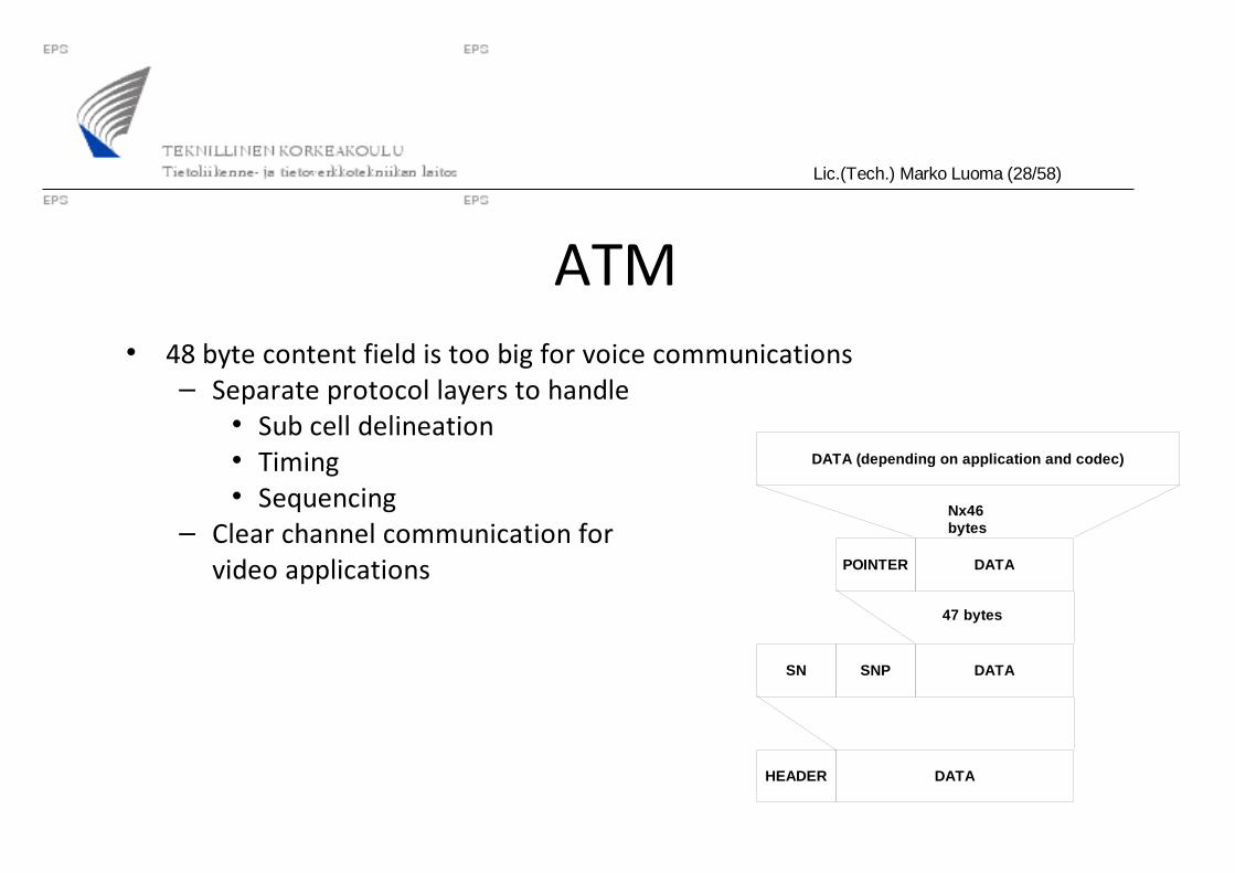
Lic.(Tech.) Marko Luoma (28/58)
ATM• 48 byte content field is too big for voice communications
– Separate protocol layers to handle• Sub cell delineation• Timing• Sequencing
– Clear channel communication forvideo applications
DATA (depending on application and codec)
DATAHEADER
DATASN SNP
DATAPOINTER
Nx46 bytes
47 bytes

Lic.(Tech.) Marko Luoma (29/58)
ATM• 48 byte content field is too little for data networks
– Fragmentation of data packets into multiple ATM cells– Separate protocol layer to handle the fragmentation and reassembly of
protocol packets
DATA (max 64kB) PAD UU-info ID LEN CRC
DATAHEADER
Nx48 bytes

Lic.(Tech.) Marko Luoma (30/58)
ATM• Framing options for IP traffic in ATM
links:– RFC2684: Multiprotocol
Encapsulation over ATM Adaptation Layer 5 (Classical IP)• Uses LLC/SNAP
encapsulation of traffic within ATM adaption layer 5 IP packet
PAD (0-47 octect)
CPCS-UU (1 octect)
CPI (1 octect) =0x00
Length (2 octect)
CRC (4 octect)
Source SAP =AA
Frame Type =03
Ethertype =08-00
Destination SAP =AA
OUI =00-00-00
AA-AA-03 -> SNAP
00-00-00 -> Ethertype08-00 -> IPv4
AAL5 -trailer
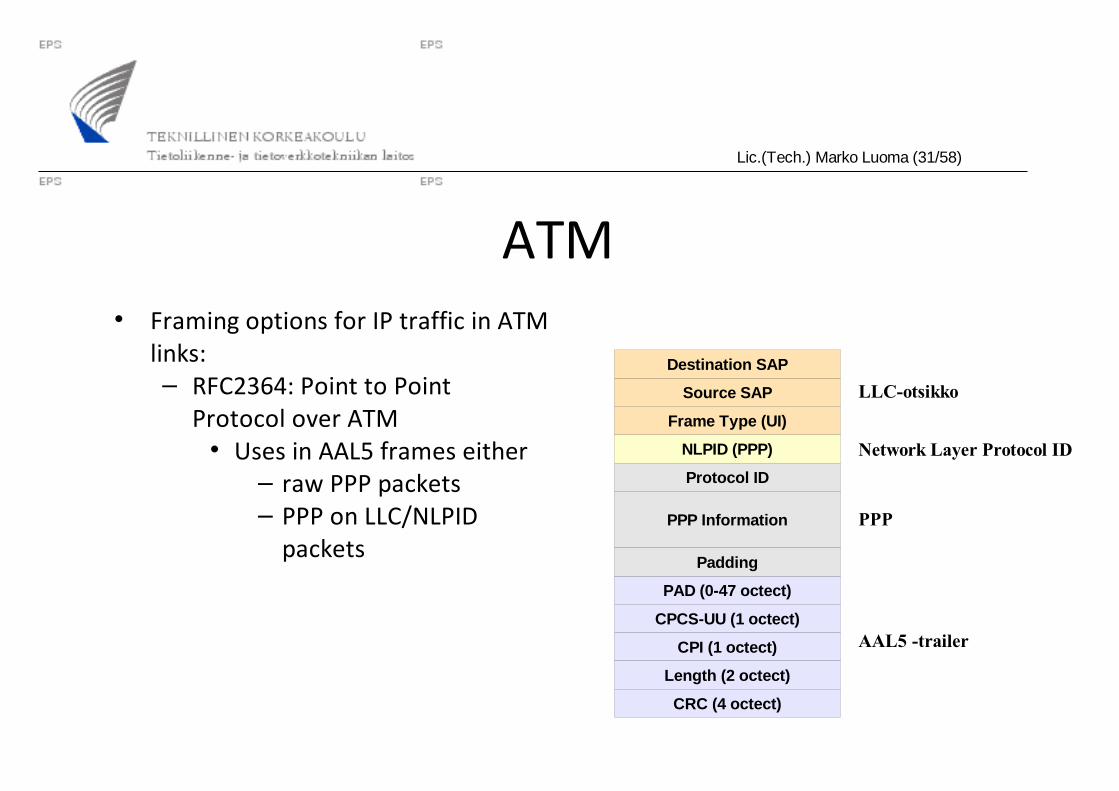
Lic.(Tech.) Marko Luoma (31/58)
ATM• Framing options for IP traffic in ATM
links:– RFC2364: Point to Point
Protocol over ATM• Uses in AAL5 frames either
– raw PPP packets– PPP on LLC/NLPID
packetsPPP Information
PAD (0-47 octect)
CPCS-UU (1 octect)
CPI (1 octect)
Length (2 octect)
CRC (4 octect)
Source SAP
Frame Type (UI)
NLPID (PPP)
Protocol ID
Padding
Destination SAP
LLC-otsikko
Network Layer Protocol ID
PPP
AAL5 -trailer

Lic.(Tech.) Marko Luoma (32/58)
ATM• ATM network is from IP
perspective– NBMA network
• Separate virtual connection between each and every router– Large number of
connections and adjacencies in routing
• Usually subinterface per connection
10.4.7.1
10.4.7.2
10.4.7.5
10.4.7.3
10.4.7.4
Lic.(Tech.) Marko Luoma (33/58)
ATM• Pros:
– Easy capacity management– Virtual short-cuts without routing– MPLS ready– Fault tolerant if ATM-level dynamic routing is used
• Cons:– Additional layer of technology
• Not good for framing itself– Expensive interfaces at routers
• Subinterface structure in networked ATM
Lic.(Tech.) Marko Luoma (34/58)
Ethernet• Technology has scaled to level where conventional core network
technologies are– STM-64 and 10GbE are the same
• Even in optical interface level they are the same but ethernet is only 20% of the price
– STM-256 will be the base for 40GbE ?– 1GbE is based on fiber channel but can be multiplexed in STM-16
networks by having two independent connections
Lic.(Tech.) Marko Luoma (35/58)
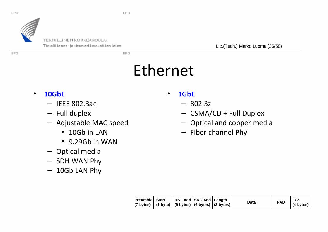
Ethernet• 10GbE
– IEEE 802.3ae– Full duplex– Adjustable MAC speed
• 10Gb in LAN• 9.29Gb in WAN
– Optical media– SDH WAN Phy– 10Gb LAN Phy
• 1GbE– 802.3z– CSMA/CD + Full Duplex– Optical and copper media– Fiber channel Phy
DataStart(1 byte)
DST Add(6 bytes)
PADPreamble(7 bytes)
FCS(4 bytes)
SRC Add(6 bytes)
Length(2 bytes)

Lic.(Tech.) Marko Luoma (36/58)
Ethernet• Possibility to build transparent LAN services
– Majority of LAN networks are build with ethernet– Some applications benefit from the fact that ethernet headers are
preserved• Possibility to have same IP subnet on both ends• WAN network is transparent for ethernet network
– No PPP protocol in between SDH and Ethernet– Core network technologies are evolving
• Metro VLAN separation• Core provider framing
Lic.(Tech.) Marko Luoma (37/58)
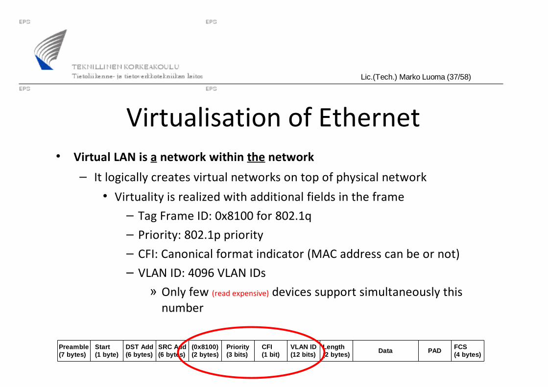
Virtualisation of Ethernet• Virtual LAN is a network within the network
– It logically creates virtual networks on top of physical network
• Virtuality is realized with additional fields in the frame– Tag Frame ID: 0x8100 for 802.1q– Priority: 802.1p priority– CFI: Canonical format indicator (MAC address can be or not)– VLAN ID: 4096 VLAN IDs
» Only few (read expensive) devices support simultaneously this number
DataStart(1 byte)
DST Add(6 bytes) PADPreamble
(7 bytes)FCS(4 bytes)
SRC Add(6 bytes)
Length(2 bytes)
Priority(3 bits)
CFI(1 bit)
(0x8100)(2 bytes)
VLAN ID(12 bits)

Lic.(Tech.) Marko Luoma (38/58)
VLAN• Separation of network resources to logical units is based on forwarding
information databased (FID)
– In independent mode, each VLAN has its own FID
• Clients residing in different forwarding table are not able to communicate without external help
– In shared mode, part of VLANs share a common FID
• Clients residing (symmetrically) in same FID are able to communicate together
• Communication between VLANs is established with
– ‘Misconfigured’ bridge that connects VLANs together
– Router forwarding packets between VLANs

Lic.(Tech.) Marko Luoma (39/58)
VLAN association• Association of devices to VLANs is based on
– Device tagging (end system is VLAN aware) – rarely
– Port based VLAN membership (switchports are assigned to particular VLAN) – commonly
– Protocol inspection (MAC address, ethertype, IP address, TCP/UDP port) – only in service switches
Lic.(Tech.) Marko Luoma (40/58)
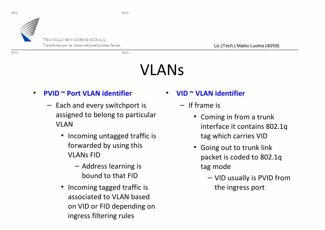
VLANs• PVID ~ Port VLAN identifier
– Each and every switchport is assigned to belong to particular VLAN
• Incoming untagged traffic is forwarded by using this VLANs FID– Address learning is
bound to that FID
• Incoming tagged traffic is associated to VLAN based on VID or FID depending on ingress filtering rules
• VID ~ VLAN identifier
– If frame is
• Coming in from a trunk interface it contains 802.1q tag which carries VID
• Going out to trunk link packet is coded to 802.1q tag mode– VID usually is PVID from
the ingress port

Lic.(Tech.) Marko Luoma (41/58)
Filtering rules• Ingress filtering rules:
– Received frame is untagged
• Forward using PVID
• Discard
– Received frame is tagged
• Forward using VID– VID = 0:
» Use only P-bits, forward using PVID– VID = 1
» Default tree, all interfaces
• Forward using PVID
• Discard
Lic.(Tech.) Marko Luoma (42/58)
Filtering rules• Egress filtering rules
– Interface is in untagged mode
• Forward untagged frame– Use configured priorities
– Interface is in tagged mode
• Set tag based on classification rules– Ingress VID– PVID
– P-bits
Lic.(Tech.) Marko Luoma (43/58)
Priority• 802.1p is amendment in 802.1q
– Allow traffic prioritization within Ethernet networks
– 3 bits -> 8 priorities
• Number of queues dependent of HW
• At minimum strict priority queuing between queues
– Mapping traffic to queues is dependent on
• Number of queues
• Configured policy (egress filtering)– MAC address– Ethertype– DSCP– Address