Embed Size (px)
Citation preview
20.11.2016
1
INF 5460Electronic noise – estimates and countermeasures
Lecture 2-3
Noise coupling (Ott2)
2.4 MUTUAL INDUCTANCE CALCULATIONS
• Biot-Savarts law:
• B is the magnetic flux density at a distance rfrom a long conductor with the current I.
• Increases with increasing I.
• Decreases with increasing r.
r
IB
2
2
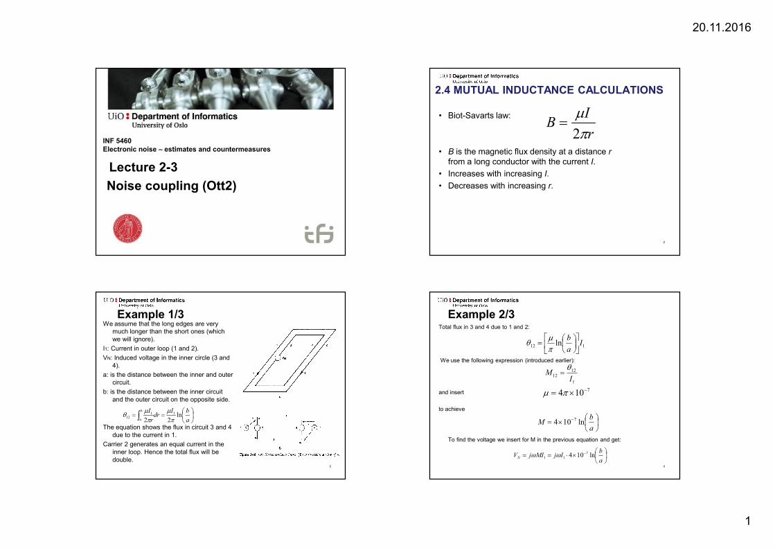
Example 1/3We assume that the long edges are very
much longer than the short ones (which we will ignore).
I1: Current in outer loop (1 and 2).
VN: Induced voltage in the inner circle (3 and 4).
a: is the distance between the inner and outer circuit.
b: is the distance between the inner circuit and the outer circuit on the opposite side.
The equation shows the flux in circuit 3 and 4 due to the current in 1.
Carrier 2 generates an equal current in the inner loop. Hence the total flux will be double.
a
bIdrr
Ib
aln
2211
12
3
Example 2/3Total flux in 3 and 4 due to 1 and 2:
We use the following expression (introduced earlier):
and insert
to achieve
To find the voltage we insert for M in the previous equation and get:
112 ln Ia
b
1
1212
IM
7104
a
bM ln104 7
a
bIjMIjVN ln104 7
11
4
20.11.2016
2
Example 3/3
Example:f = 10MHz
I1= 100A
a= 10m
b= 3000m
VN=14mV
5
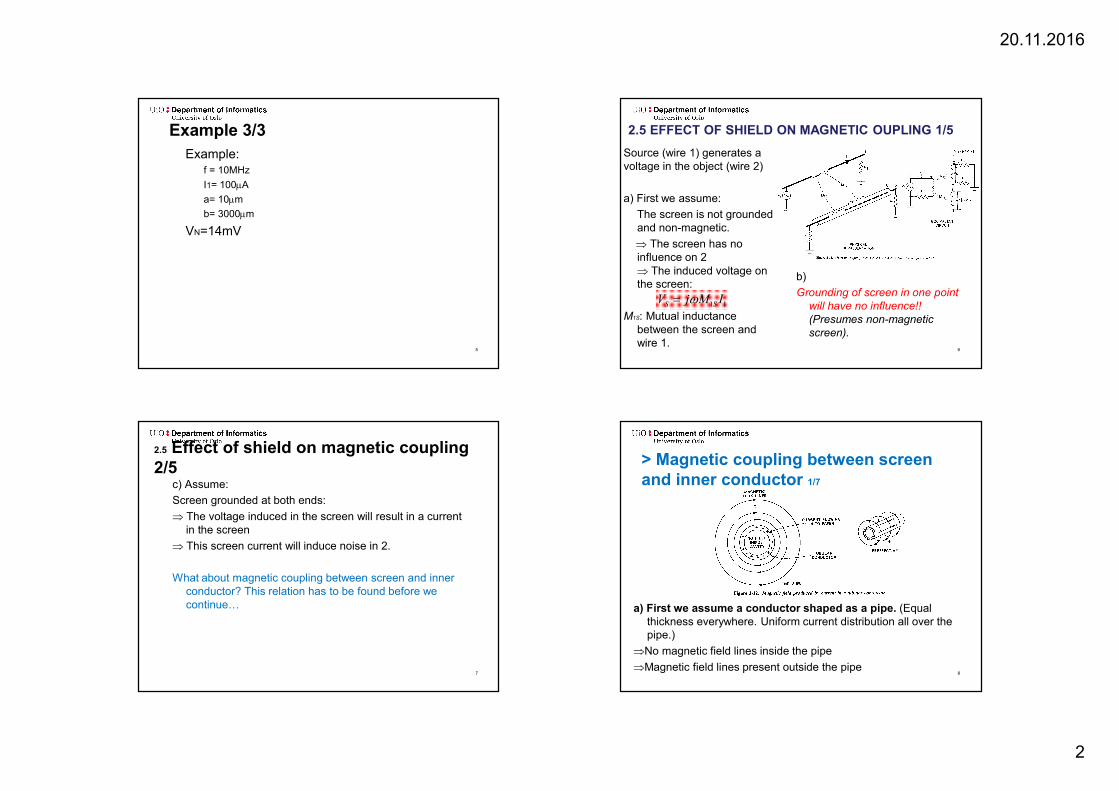
2.5 EFFECT OF SHIELD ON MAGNETIC OUPLING 1/5
Source (wire 1) generates a voltage in the object (wire 2)
a) First we assume:
The screen is not grounded and non-magnetic.
The screen has no influence on 2 The induced voltage on the screen:
M1S: Mutual inductance between the screen and wire 1.
11 IMjV SS
b)
Grounding of screen in one point will have no influence!! (Presumes non-magnetic screen).
6
2.5 Effect of shield on magnetic coupling 2/5
c) Assume:
Screen grounded at both ends:
The voltage induced in the screen will result in a current in the screen
This screen current will induce noise in 2.
What about magnetic coupling between screen and inner conductor? This relation has to be found before we continue…
7
> Magnetic coupling between screen and inner conductor 1/7
a) First we assume a conductor shaped as a pipe. (Equal thickness everywhere. Uniform current distribution all over the pipe.)
No magnetic field lines inside the pipe
Magnetic field lines present outside the pipe8
20.11.2016
3
The mutual inductance between screen and conductor is equal to the inductance of the screen!
>Magnetic coupling between screen and …2/7
b) Conductor inside pipe (for example a Coax).
LS: Screen inductance (”pipe”)
IS: Screen current (”pipe”)
s: Field generated by screen: Encloses both screen and conductor
M: Mutual inductance
Since S=C we will have the important equation:
S
SS
IL
S
C
IM
SLM
9
>Magnetic coupling between screen and …3/7
We repeat our assumptions::
• No field lines in the screen
• Uniform current distribution in the screen
We did not require:
• That the inner conductor is centrally situated in the screen (i.e. does not have to be a coax).
10
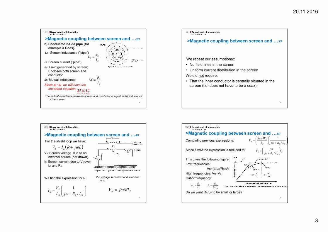
>Magnetic coupling between screen and …4/7
For the shield loop we have:
VS: Screen voltage due to an external source (not drawn).
IS: Screen current due to VS overLS and RS.
We find the expression for IS:
SN MIjV
LjRIV SS
SSS
SS
LRjL
VI
/
1
VN: Voltage in centre conductor due to IS
11
>Magnetic coupling between screen and …5/7
Combining previous expressions:
Since LS=M the expression is reduced to:
This gives the following figure:
Low frequencies:
VN=(jLS/RS)VS
High frequencies: VN=VS
Cut-off frequency:
Do we want RS/LS to be small or large?
SSS
SN
LRjL
MVjV
/
1
S
SS
N VLRj
jV
/
S
Sc
L
R
S
Sc
L
Rf
2
12
20.11.2016
4
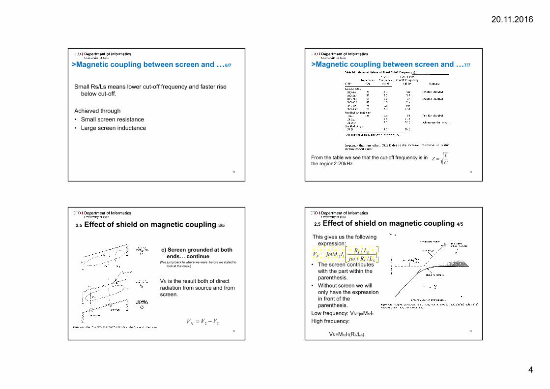
>Magnetic coupling between screen and …6/7
Small Rs/Ls means lower cut-off frequency and faster rise below cut-off.
Achieved through
• Small screen resistance
• Large screen inductance
13
>Magnetic coupling between screen and …7/7
X
From the table we see that the cut-off frequency is in the region2-20kHz. C
LZ
14
2.5 Effect of shield on magnetic coupling 3/5
c) Screen grounded at both ends… continue
(We jump back to where we were before we stated to look at the coax.)
VN is the result both of direct radiation from source and from screen.
CN VVV 2
15
2.5 Effect of shield on magnetic coupling 4/5
This gives us the following expression:
• The screen contributes with the part within the parenthesis.
• Without screen we will only have the expression in front of the parenthesis.
Low frequency: VN=jM12I1
High frequency:
VN=M12I1(RS/LS)
SS
SSN
LRj
LRIMjV
/
/112
16
20.11.2016
5
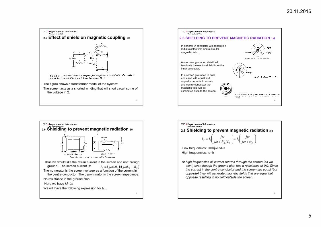
2.5 Effect of shield on magnetic coupling 5/5
The figure shows a transformer model of the system:
The screen acts as a shorted winding that will short circuit some of the voltage in 2.
17
In general: A conductor will generate a radial electric field and a circular magnetic field.
2.6 SHIELDING TO PREVENT MAGNETIC RADIATION 1/4
In a screen grounded in both ends and with equal and opposite currents in screen and centre conductor the magnetic field will be eliminated outside the screen.
A one point grounded shield will terminate the electrical field from the inner conductor.
18
2.6 Shielding to prevent magnetic radiation 2/4
Thus we would like the return current in the screen and not through ground. The screen current is:
The numerator is the screen voltage as a function of the current in the centre conductor. The denominator is the screen impedance.
No resistance in the ground plan!
Here we have M=LS.
We will have the following expression for IS…
SSS RLjMIjI /1
19
2.6 Shielding to prevent magnetic radiation 3/4
Low frequencies: IS=I1jLS/RS
High frequencies: IS=I1
At high frequencies all current returns through the screen (as we want) even though the ground plan has a resistance of 0. Since the current in the centre conductor and the screen are equal (but opposite) they will generate magnetic fields that are equal but opposite resulting in no field outside the screen.
CSS
Sj
jI
LRj
jII
11
20

20.11.2016
6
2.6 Shielding to prevent magnetic radiation 4/4
If the circuitry on the right side is not grounded neither should the screen. This ensures that the return current is forced to pass through the screen and there will not be generated a magnetic field, neither at low frequencies.
21
2.7 SHIELDING A RECEPTOR AGAINST MAGNETIC FIELDS 1/2
The best strategy for protection of magnetic fields is to reduce the area of the circuit loops!
NB! In particular it is important to know (and control) how the return current passes through ground. Often it takes another route than intended by the designer and may have a larger loop than planned.
About screen: If a screen results in that the return current finds another path resulting in a smaller loop, this will give better protection. The protection is due to the reduced loop size and not due to a magnetic protection of the cable.
22
2.7 Shielding a receptor against magnetic fields 2/2
The solution in fig 2-24 B is the preferred of the three alternatives but has some limitations:
• Low efficiency at low frequencies
• Noise generated in the screen will result in a voltage difference and thus it self be a noise source.
• A difference in ground potential between the two ends of the shield will imply a noise source in the circuit.
I.e. magnetic good but electrical bad.
The noise voltage generated is the noise current times the screen impedance.
23
2.8 COMMON IMPEDANCE SHIELD COUPLING
SSSSSIN IRILjMIjV
SSIN IRV
We will look at the expression for the voltage at the amplifier input due to the noise current through the shield. The current in the centre conductor and the shield is equal and since M=Ls the voltage drop over both coils will eliminate each other and the following expression remains:
24

20.11.2016
7
X TP: Twisted pair
TP as receiver (left figure): Fields outside the twins will be about similar in both directions and then almost cancel each other. The field inside each twin will generate a potential but be almost cancelled by opposite potentials in the neighbour twins.
TP as source (right figure): The areas outside the twins will experience almost equal but opposite fields from the two wires and thus the resulting field will be almost zero. Within each twin the field from the wires will add up. However the neighbours will have opposite direction so that at some distance they will cancel.
The best noise reduction is achieved with dense twins so that the field within each twin each is cancelled by an equal sized and opposite field in neighbour twins. The distance to source/receiver and the homogeneity of the field is also important.
25
2.9 EXPERIMENTAL DATA 1/6
Test setup:
L2 is the cable under test.
The frequency used is 50kHz (which is significantly above the corner frequency of all the test cables).
Cable setup A-F (first figure) are grounded through a load at both ends.
Cable setup G-K (second figure) has a grounded load in only one end.
The noise measured in setup A are used as an reference.26
2.9 Experimental data 2/6
27
2.9 Experimental data 3/6
A and B: No attenuation due to the shield.
C: Better attenuation but noise will be generated.
D: Twisted pair gives some attenuation. However some of the return current will not pass through the ground wire. Hence the sensitive receiving area for the magnetic field will be larger than the cable.
E: Adding a shield and ground in one end only has no effect.
F: Grounding the shield in both ends has better attenuation (similar to a coax grounded at both ends).
Preferably none of this solutions should be used. If the load has to be grounded at both ends, alternative C and F should be chosen.
28

20.11.2016
8
2.9 Experimental data 4/6
29
2.9 Experimental data 5/6
All: One point ground gives significant reduction in noise.
G: Reduced loop gives reduced M-field. Grounded shield gives reduced E-influence.
H: Twisted pair reduces M-field but still sensitive to E-field.
I: One point grounded shield reduces E-field (but not M-field). However the twisting gives a significant reduction of the influence from the M-field.
J: Two point grounding establishes an external ground loop that gives worse attenuation.
K: External ground loop is removed and screen reduces some of the M-field.
More attenuation in G than in I is probably due that the G loop is smaller than the Iloop in this case. Generally this is not correct.
Increased twin density will give better attenuation. A TP cat 3 has about one twin for each 5 cm. For TP cat 5 the density is increased to one twin per cm.
Normally I will be preferred over G at low frequencies since ground as shield and ground as signal return is separated.
30
2.9 Experimental data 6/6
J: Grounding shield at both ends gives somewhat reduced effect compared to I. This is due to the high shield current in the ground loop formed by the shield inducing unequal voltages in the ground loop formed by the shield inducing unequal voltages in the two centre conductors.
K: Has the advantages of coax and twisted pair and better attenuation. However K is often not chosen because noise pick up in the shield can propagate through signal wires. Generally the best solution is to have one common grounding point.
Solution I with more dense twisting is thus probably the best solution.
31
2.10 EXAMPLE OF SELECTIVE SHIELDING 1/3
Shielded loop antenna:
• The shield protects against the electrical field while magnetic field is measured influenced by the shield.
• Application examples: – Radio bearing
– Reduction of noise in receivers (Most locally generated noise is electrical fields).
32

20.11.2016
9
2.10 Example of selective shielding 2/3
A) First we look at the basic loop antenna:
The voltage generated in the loop by the magnetic field is:
(B: magnetic field, A: area, : angel between field and the normal of the loop area.
The antenna is a vertical antenna for the electrical field.
E: Electrical field
2A/: Efficient height for circular antenna
’: angel between electrical field and the normal of the loop area.
cos2 fBAVm
'cos2
AEVe
33
2.10 Examples of selective shielding 3/3
B) Full shield
… electric field stopped by shield
… shield current due to magnetic field will establish an opposite magnetic field viewed by the antenna. Hence the antenna will not measure the electrical field
C) Loop with split shield
… electric field stopped by shield (except at split)
… no magnetic induced current in shield hence the inner conductor will measure the full magnetic field.
Thus: Radio waves consist both of electrical and magnetic fields. We can develop an antenna that is only sensitive to the magnetic field. This may be useful to reduce the influence from the stronger local electrical field.
34
2.12 COAXIAL CABLE VERSUS TWISTED PAIR 1/3
Comments to figure: More modern twisted pair have lower capacitance and better high frequency characteristics.
Example: Coax (RG58U): 95pF/m, Kat 5 TP: 56pF/m 100MHz
(Values 2006).
Twisted pair: Good at low frequencies. Good protection to magnetic fields.
Coax: More uniform characteristic impedance. Suited from DC to several hundred MHz.
35
2.12 Coaxial cable versus twisted pair 2/3
Coax:
Coax grounded in one point:
• Protects towards electrical fields.
• Noise current will result in a noise voltage (noise current x cable impedance) which will be in series with the signal source.
Triax (double shield) may be an option:
• Noise current in outer shield.
• Signal current in inner shield.
• However triax cables are expensive and more difficult to handle!
At higher frequencies (>>1MHz) the coax will work as an triax due to the skin effect.
TP:
FTP (STP, S/FTP): (F: Foil, S: Stocking)
• About the same characteristics as the triax.
• Lower price and simple to handle.
• Signal current in the twisted conductors and noise in the shield.
• When shield noise is induced equal in both twisted conductors, the difference over the pair will not change. 36
20.11.2016
10
2.12 Coaxial cable versus twisted pair 3/3
UTP (no shield):
• Good magnetic protection
• Bad protection towards electrical fields if the termination is not correct.
STP/FTP gives best protection at low frequencies when magnetic fields is a main problem.
The denser twisting the better protection!
37
Stocking shields (contra foil) 1/2
• Stocking more used than foil.
• More flexible and better mechanical strength when the cable is mobile.
• Stockings cover 60-98% of the area
• A little worse protection towards E-fields.
• 5-30dB worse protection towards M-fields.
• Further reduced efficiency at very high frequencies (UHF) both for E and M fields.
38
Stocking shields (contra foil) 2/2
• Aluminium foil as shield
– Cover almost 100%.
– Better protection towards E-field
– Not as mechanical robust as stockings.
– Difficult to terminate cable properly.
• The combination of foil and stockings…
take the best from both.
39
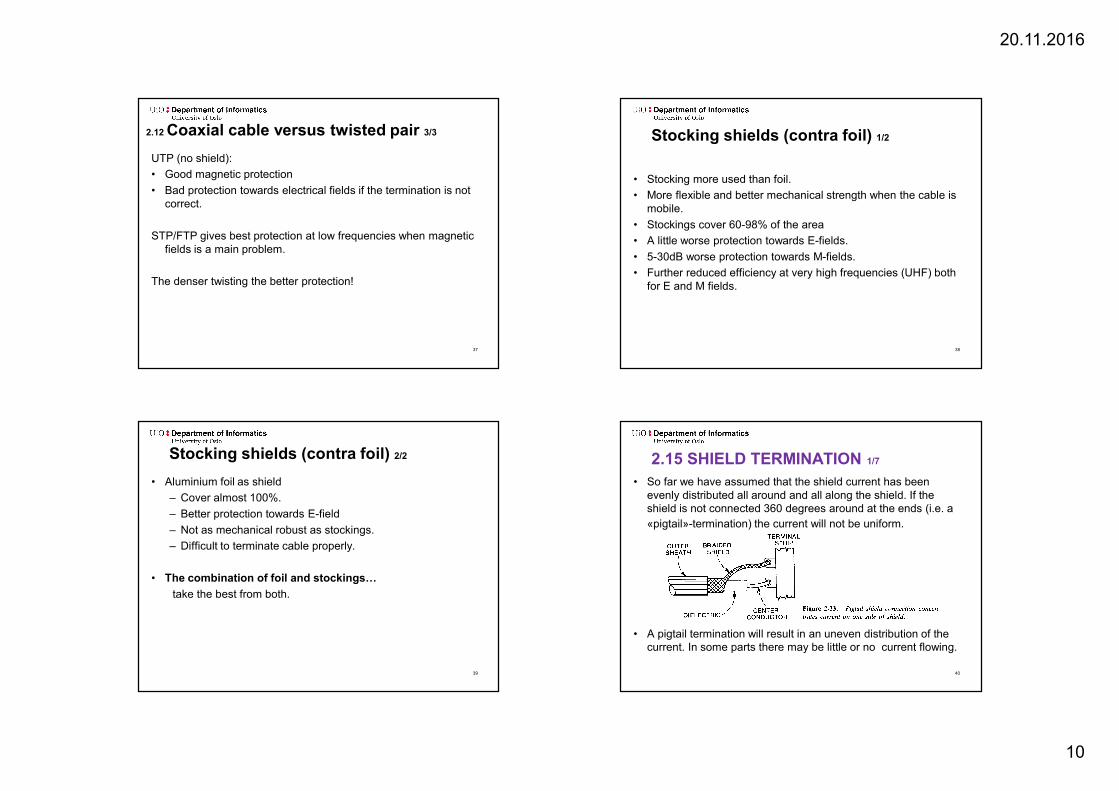
2.15 SHIELD TERMINATION 1/7
• So far we have assumed that the shield current has been evenly distributed all around and all along the shield. If the shield is not connected 360 degrees around at the ends (i.e. a
«pigtail»-termination) the current will not be uniform.
• A pigtail termination will result in an uneven distribution of the current. In some parts there may be little or no current flowing.
40

20.11.2016
11
2.15 Shield termination 2/7
• For maximum protection the connection between the shield and the contact should be all-around (360 degrees).
• Recommended coax contacts are BNC, UHF and N-type contacts.
41
2.15 Shield termination 3/7
• The figure shows an example of an improved termination but without 360 degree connection.
42
2.15 Shield termination 4/7
Example: 3.7 m long shielded cable with 8 cm pigtail and 50 termination impedance. Three noise contributions:
• Inductive coupling to shield
• Inductive coupling to pigtail
• Capacitive coupling to pigtail
According to the figure the pigtail inductance is dominating above 100kHz.
43
2.15 Shield termination 5/7
Example: As previous example but with 1000termination resistance.
Inductive coupling at pigtail decreases
Capacitive coupling at pigtail increases and are dominating above 10kHz
Inductive coupling to shield decreases
Total noise coupling decreases
44
20.11.2016
12
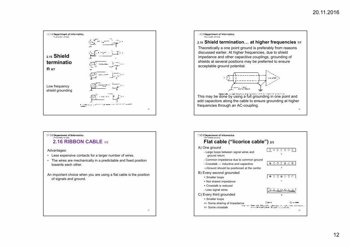
2.15 Shield termination 6/7
Low frequency shield grounding
45
2.15 Shield termination… at higher frequencies 7/7
Theoretically a one point ground is preferably from reasons discussed earlier. At higher frequencies, due to shield impedance and other capacitive couplings, grounding of shields at several positions may be preferred to ensure acceptable ground potential.
This may be done by using a full grounding in one point and add capacitors along the cable to ensure grounding at higher frequencies through an AC-coupling.
46
2.16 RIBBON CABLE 1/3
Advantages:
• Less expensive contacts for a larger number of wires.
• The wires are mechanically in a predictable and fixed position towards each other.
An important choice when you are using a flat cable is the position of signals and ground.
47
Flat cable (“licorice cable”) 2/3
A) One ground- Large loops between signal wires and
ground return
- Common impedance due to common ground
- Crosstalk --- inductive and capacitive
Ground should be positioned at the centre
B) Every second grounded+ Smaller loops
+ Not shared impedance
+ Crosstalk is reduced
- Less signal wires
C) Every third grounded+ Smaller loops
+/- Some sharing of impedance
+/- Some crosstalk48

20.11.2016
13
Flat cable (“licorice cable”) 3/3
D) Ground plan The conductors are closer to the ground than to each other.
Smaller loops than for option B)
The return current will chose a path beneath the signal wire it belongs (ref the grounding and shields for M-field discussion)
Smaller loops
But how is the ground plan connected?
If the ground plan is not connected in full width the ground current will be forced away from each signal wire and the efficient loop area will be larger.
Shielded flat cable is also available but requires 360 degree contact to have full effect.
Palmgren 1981: Conductors on the edges had 7dB poorer shield effect than the conductors in the middle.
Flat cables are available as uniform flat and twisted where two and two are twisted.
49
“Long cables” 1/2
• In the expressions we have used so far it may seems as capacitive and inductive coupling grows with frequency to infinity. This is not correct. The expressions are only valid when the cables are relatively short compared to the wave lengths.
• At this short lengths we can simplify and assume that the current in a wire are in the same phases all along the cable.
• At /4 the coupling starts to decrease. At /2 it reaches a minimum before it starts to grow again. 50
“Long cables” 2/2
We also see:
• The coupling factor will have a maximum depending on the cable length and the wavelength of the noise signal.
• Maximum is achieved at /4. Above this frequency the coupling factor will fluctuate.
51