Embed Size (px)
Citation preview

Lecture 11: Networks & Networking

Lecture 11 / Page 2 AE4B33OSS Silberschatz, Galvin and Gagne ©2005
Contents
Distributed systems Network types Network standards ISO and TCP/IP network models Internet architecture IP addressing IP datagrams
Lecture 11 / Page 3 AE4B33OSS Silberschatz, Galvin and Gagne ©2005
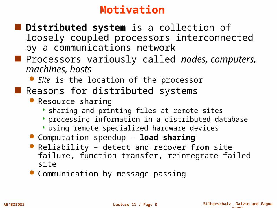
Motivation
Distributed system is a collection of loosely coupled processors interconnected by a communications network
Processors variously called nodes, computers, machines, hosts Site is the location of the processor
Reasons for distributed systems Resource sharing
sharing and printing files at remote sites processing information in a distributed database using remote specialized hardware devices
Computation speedup – load sharing Reliability – detect and recover from site failure, function transfer,
reintegrate failed site Communication by message passing
Lecture 11 / Page 4 AE4B33OSS Silberschatz, Galvin and Gagne ©2005
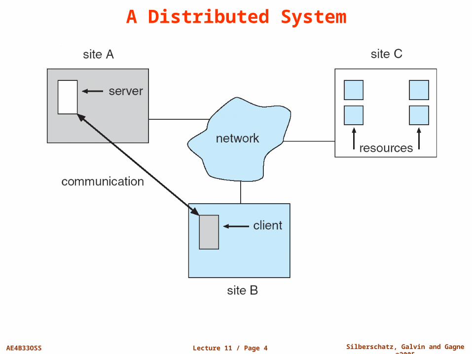
A Distributed System
Lecture 11 / Page 5 AE4B33OSS Silberschatz, Galvin and Gagne ©2005
Types of Distributed Operating Systems
Network Operating Systems Users are aware of multiplicity of machines. Access to resources
of various machines is done explicitly by: Remote logging into the appropriate remote machine (telnet, ssh) Transferring data from remote machines to local machines, via the
File Transfer Protocol (FTP) mechanism
Distributed Operating Systems Features follow
Lecture 11 / Page 6 AE4B33OSS Silberschatz, Galvin and Gagne ©2005
Distributed Operating Systems Users not aware of multiplicity of machines
Access to remote resources similar to access to local resources Data Migration – transfer data by transferring entire file, or
transferring only those portions of the file necessary for the immediate task
Computation Migration – transfer the computation, rather than the data, across the system
Process Migration – execute an entire process, or parts of it, at different sites Load balancing – distribute processes across network to even the
workload Computation speedup – subprocesses can run concurrently on
different sites Hardware preference – process execution may require
specialized processor Software preference – required software may be available at only
a particular site Data access – run process remotely, rather than transfer all data
to the local machine
Lecture 11 / Page 7 AE4B33OSS Silberschatz, Galvin and Gagne ©2005
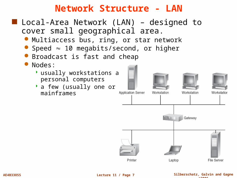
Network Structure - LAN Local-Area Network (LAN) – designed to cover small
geographical area. Multiaccess bus, ring, or star network Speed 10 megabits/second, or higher Broadcast is fast and cheap Nodes:
usually workstations and/or personal computers
a few (usually one or two) mainframes
Lecture 11 / Page 8 AE4B33OSS Silberschatz, Galvin and Gagne ©2005
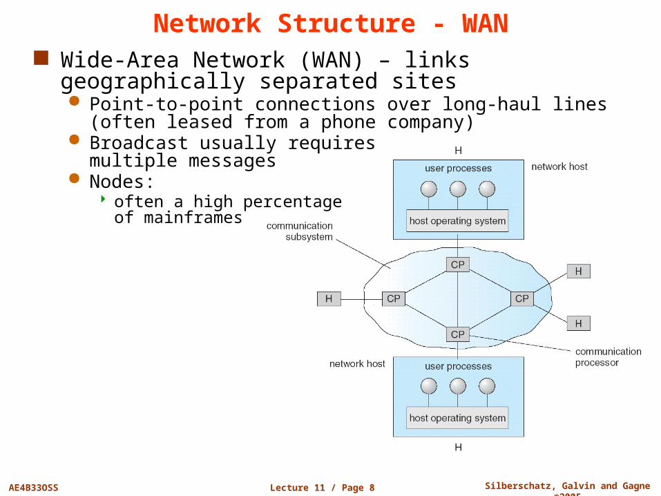
Network Structure - WAN Wide-Area Network (WAN) – links geographically
separated sites Point-to-point connections over long-haul lines (often leased from
a phone company) Broadcast usually requires
multiple messages Nodes:
often a high percentage of mainframes
Lecture 11 / Page 9 AE4B33OSS Silberschatz, Galvin and Gagne ©2005
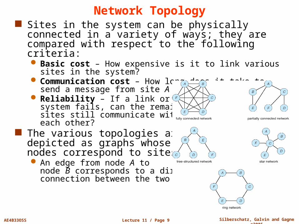
Network Topology Sites in the system can be physically connected in a
variety of ways; they are compared with respect to the following criteria: Basic cost – How expensive is it to link various sites in the
system? Communication cost – How long does it take to send a
message from site A to site B? Reliability – If a link or a site in the
system fails, can the remaining sites still communicate with each other?
The various topologies are depicted as graphs whose nodes correspond to sites An edge from node A to
node B corresponds to a direct connection between the two sites
Lecture 11 / Page 10 AE4B33OSS Silberschatz, Galvin and Gagne ©2005
Communication Structure
The design of a communication network must address four basic issues:
Naming and name resolution How do two processes locate each other to communicate?
Routing strategies How are messages sent through the network?
Connection strategies How do two processes send a sequence of messages?
Contention The network is a shared resource, so how do we resolve
conflicting demands for its use?
Lecture 11 / Page 11 AE4B33OSS Silberschatz, Galvin and Gagne ©2005
Naming and Name Resolution Name systems in the network Address messages with the process-identifier Identify processes on remote systems by
<host-identifier, process-identifier> pair
Domain name service (DNS) Specifies the naming structure of the hosts, as well as name to
address resolution (Internet)
Lecture 11 / Page 12 AE4B33OSS Silberschatz, Galvin and Gagne ©2005
Routing Strategies Fixed routing - A path from A to B is specified in advance
Path changes only if a hardware failure disables it Since the shortest path is usually chosen, communication costs are
minimized Fixed routing cannot adapt to load changes Ensures that messages will be delivered in the order in which they
were sent Virtual circuit - A path from A to B is fixed for the duration
of one session. In different sessions messages from A to B may have different paths;
Partial remedy to adapting to load changes Ensures that messages will be delivered in the order in which they
were sent Dynamic routing – The path used to send a message form
site A to site B is chosen only when a message is sent Usually a site sends a message to another site on the link least used
at that particular time Adapts to load changes by avoiding routing messages on heavily
used path Messages may arrive out of order
This problem can be fixed by sequentially numbering the messages

Lecture 11 / Page 13 AE4B33OSS Silberschatz, Galvin and Gagne ©2005
Connection Strategies Circuit switching - A permanent physical link is
established for the duration of the communication (i.e., telephone system)
Message switching - A temporary link is established for the duration of one message transfer (i.e., post-office mailing system)
Packet switching - Messages of variable length are divided into fixed-length packets which are sent to the destination Each packet may take a different path through the network The packets must be reassembled into messages as they arrive
Circuit switching requires setup time, but incurs less overhead for shipping each message, and may waste network bandwidth Message and packet switching require less setup time, but incur
more overhead per message
Lecture 11 / Page 14 AE4B33OSS Silberschatz, Galvin and Gagne ©2005
Contention
CSMA/CD - Carrier sense with multiple access (CSMA); collision detection (CD) A site determines whether another message is currently being
transmitted over that link. If two or more sites begin transmitting at exactly the same time, then they will register a CD and will stop transmitting
When the system is very busy, many collisions may occur, and thus performance may be degraded
CSMA/CD is used successfully in the Ethernet system, the most common network system
Several sites may want to transmit information over a link simultaneously. Techniques to avoid repeated collisions include:

Lecture 11 / Page 15 AE4B33OSS Silberschatz, Galvin and Gagne ©2005
Contention (Cont.) Token passing - A unique message type, known as a
token, continuously circulates in the system (usually a ring structure) A site that wants to transmit information must wait until the token
arrives When the site completes its round of message passing, it
retransmits the token A token-passing scheme is used by some IBM and HP/Apollo
systems Message slots - A number of fixed-length message slots
continuously circulate in the system (usually a ring structure) Since a slot can contain only fixed-sized messages, a single
logical message may have to be broken down into a number of smaller packets, each of which is sent in a separate slot
This scheme has been adopted in the experimental Cambridge Digital Communication Ring
General problem with the ring structure Ring break

Lecture 11 / Page 16 AE4B33OSS Silberschatz, Galvin and Gagne ©2005
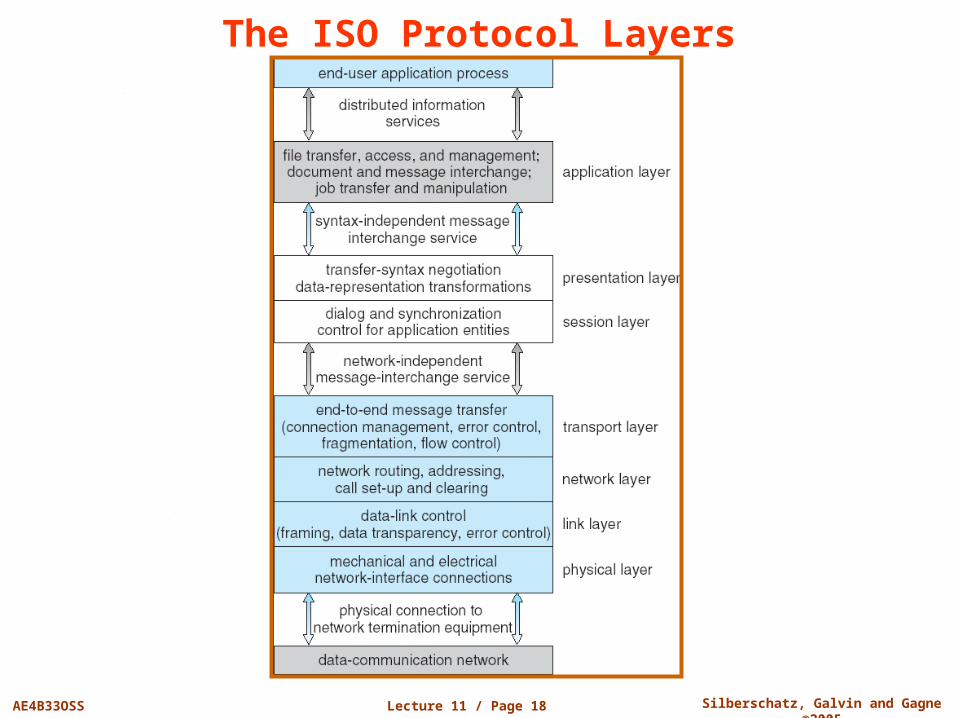
Communication Protocol
Physical layer – handles the mechanical and electrical details of the physical transmission of a bit stream
Data-link layer – handles the frames, or fixed-length parts of packets, including any error detection and recovery that occurred in the physical layer
Network layer – provides connections and routes packets in the communication network, including handling the address of outgoing packets, decoding the address of incoming packets, and maintaining routing information for proper response to changing load levels
The communication network is partitioned into the following multiple layers:
Lecture 11 / Page 17 AE4B33OSS Silberschatz, Galvin and Gagne ©2005
Communication Protocol (Cont.) Transport layer – responsible for low-level network
access and for message transfer between clients, including partitioning messages into packets, maintaining packet order, controlling flow, and generating physical addresses
Session layer – implements sessions, or process-to-process communications protocols
Presentation layer – resolves the differences in formats among the various sites in the network, including character conversions, and half duplex/full duplex (echoing)
Application layer – interacts directly with the users’ deals with file transfer, remote-login protocols and electronic mail, as well as schemas for distributed databases, etc.
Lecture 11 / Page 18 AE4B33OSS Silberschatz, Galvin and Gagne ©2005
The ISO Protocol Layers
Lecture 11 / Page 19 AE4B33OSS Silberschatz, Galvin and Gagne ©2005
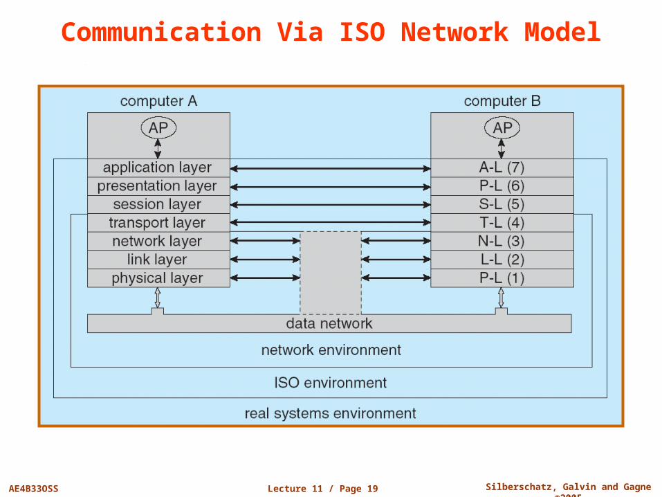
Communication Via ISO Network Model
Lecture 11 / Page 20 AE4B33OSS Silberschatz, Galvin and Gagne ©2005
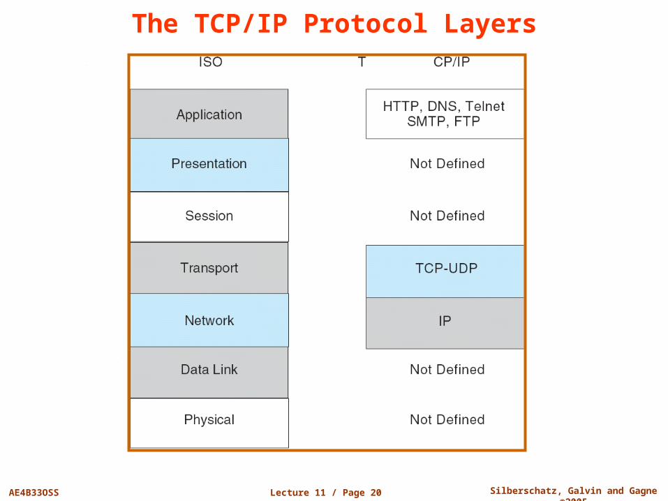
The TCP/IP Protocol Layers
Lecture 11 / Page 21 AE4B33OSS Silberschatz, Galvin and Gagne ©2005
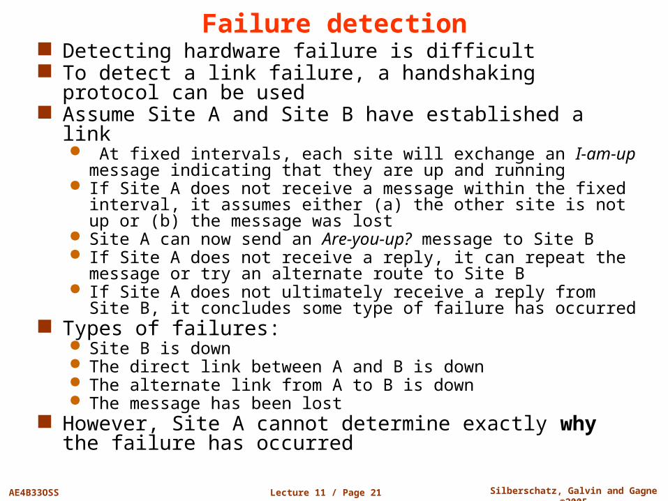
Failure detection Detecting hardware failure is difficult To detect a link failure, a handshaking protocol can be
used Assume Site A and Site B have established a link
At fixed intervals, each site will exchange an I-am-up message indicating that they are up and running
If Site A does not receive a message within the fixed interval, it assumes either (a) the other site is not up or (b) the message was lost
Site A can now send an Are-you-up? message to Site B If Site A does not receive a reply, it can repeat the message or try
an alternate route to Site B If Site A does not ultimately receive a reply from Site B, it
concludes some type of failure has occurred Types of failures:
Site B is down The direct link between A and B is down The alternate link from A to B is down The message has been lost
However, Site A cannot determine exactly why the failure has occurred
Lecture 11 / Page 22 AE4B33OSS Silberschatz, Galvin and Gagne ©2005
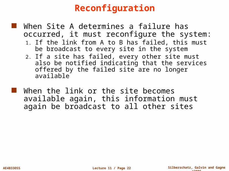
Reconfiguration
When Site A determines a failure has occurred, it must reconfigure the system:1. If the link from A to B has failed, this must be broadcast to every
site in the system2. If a site has failed, every other site must also be notified
indicating that the services offered by the failed site are no longer available
When the link or the site becomes available again, this information must again be broadcast to all other sites
Lecture 11 / Page 23 AE4B33OSS Silberschatz, Galvin and Gagne ©2005
Design Issues Transparency – the distributed system should appear as
a conventional, centralized system to the user
Fault tolerance – the distributed system should continue to function in the face of failure
Scalability – as demands increase, the system should easily accept the addition of new resources to accommodate the increased demand
Clusters – a collection of semi-autonomous machines that acts as a single system
Lecture 11 / Page 24 AE4B33OSS Silberschatz, Galvin and Gagne ©2005
Example: Networking The transmission of a network packet between hosts on
an Ethernet network Every host has a unique IP address and a corresponding
Ethernet (MAC) address Communication requires both addresses Domain Name Service (DNS) can be used to acquire IP
addresses Address Resolution Protocol (ARP) is used to map MAC
addresses to IP addresses If the hosts are on the same network, ARP can be used
If the hosts are on different networks, the sending host will send the packet to a router which routes the packet to the destination network
Lecture 11 / Page 25 AE4B33OSS Silberschatz, Galvin and Gagne ©2005
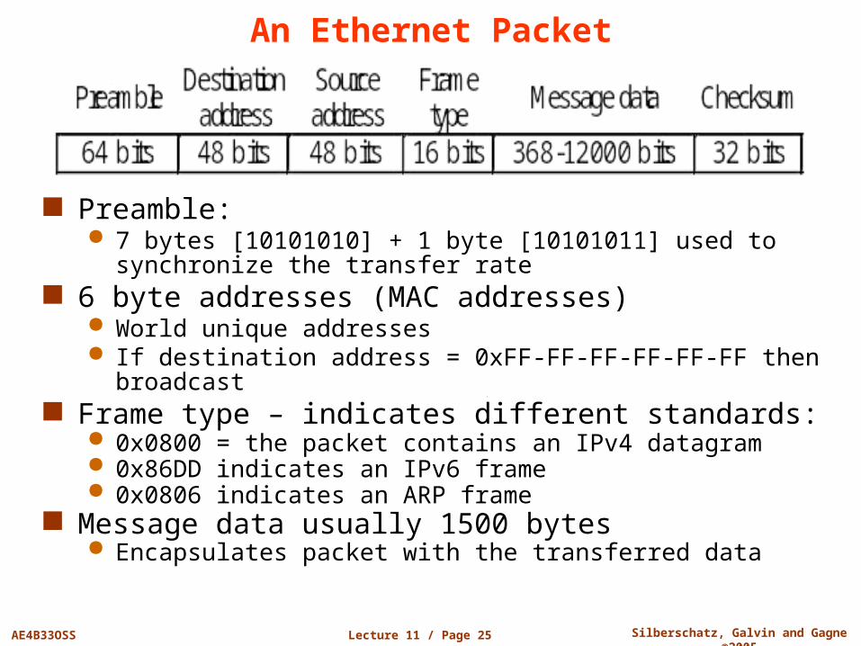
An Ethernet Packet
Preamble: 7 bytes [10101010] + 1 byte [10101011] used to synchronize the
transfer rate 6 byte addresses (MAC addresses)
World unique addresses If destination address = 0xFF-FF-FF-FF-FF-FF then broadcast
Frame type – indicates different standards: 0x0800 = the packet contains an IPv4 datagram 0x86DD indicates an IPv6 frame 0x0806 indicates an ARP frame
Message data usually 1500 bytes Encapsulates packet with the transferred data
Lecture 11 / Page 26 AE4B33OSS Silberschatz, Galvin and Gagne ©2005
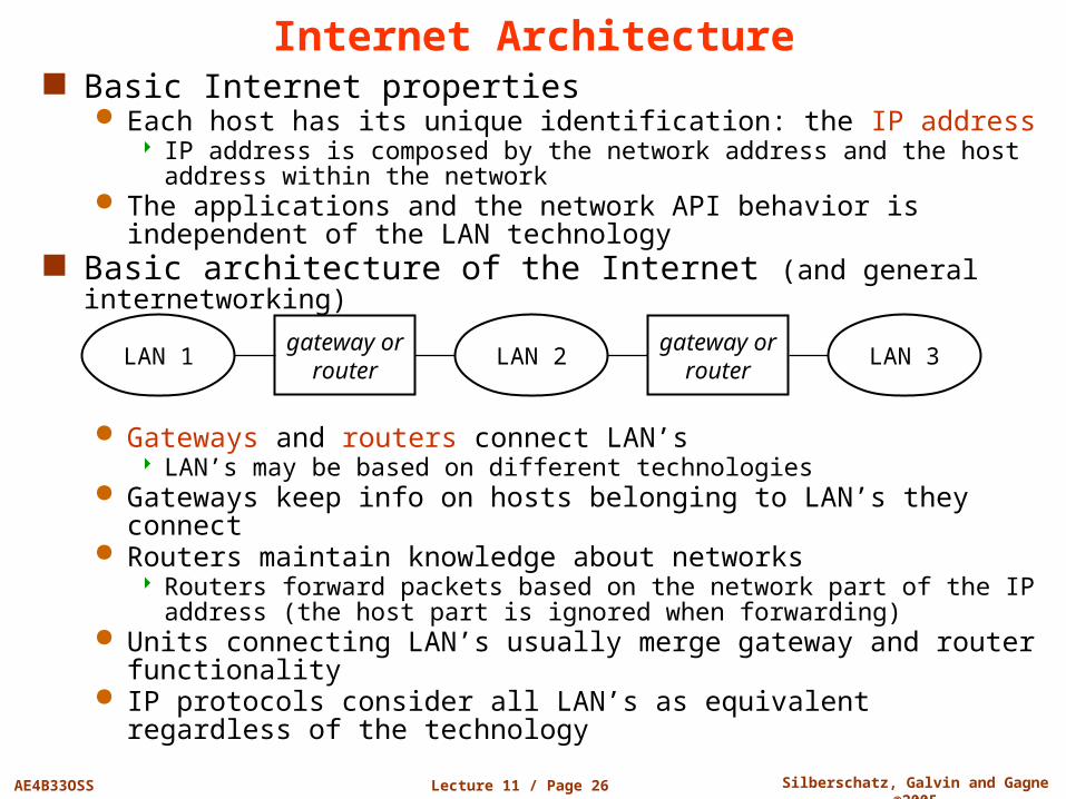
Internet Architecture Basic Internet properties
Each host has its unique identification: the IP address IP address is composed by the network address and the host address
within the network The applications and the network API behavior is independent of the
LAN technology Basic architecture of the Internet (and general internetworking)
Gateways and routers connect LAN’s LAN’s may be based on different technologies
Gateways keep info on hosts belonging to LAN’s they connect Routers maintain knowledge about networks
Routers forward packets based on the network part of the IP address (the host part is ignored when forwarding)
Units connecting LAN’s usually merge gateway and router functionality
IP protocols consider all LAN’s as equivalent regardless of the technology
LAN 1 LAN 2 LAN 3gateway or
routergateway or
router
Lecture 11 / Page 27 AE4B33OSS Silberschatz, Galvin and Gagne ©2005
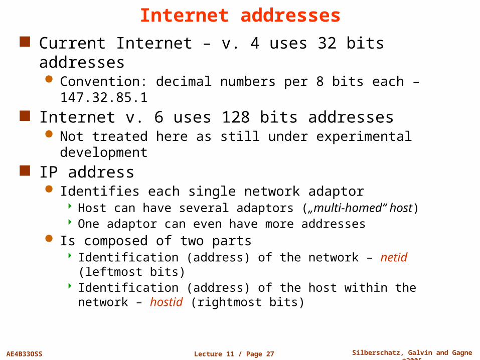
Internet addresses Current Internet – v. 4 uses 32 bits addresses
Convention: decimal numbers per 8 bits each – 147.32.85.1 Internet v. 6 uses 128 bits addresses
Not treated here as still under experimental development IP address
Identifies each single network adaptor Host can have several adaptors („multi-homed“ host) One adaptor can even have more addresses
Is composed of two parts Identification (address) of the network – netid (leftmost bits) Identification (address) of the host within the network – hostid (rightmost
bits)
Lecture 11 / Page 28 AE4B33OSS Silberschatz, Galvin and Gagne ©2005
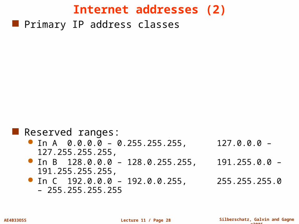
Internet addresses (2) Primary IP address classes
Reserved ranges: In A 0.0.0.0 – 0.255.255.255, 127.0.0.0 – 127.255.255.255, In B 128.0.0.0 – 128.0.255.255, 191.255.0.0 – 191.255.255.255, In C 192.0.0.0 – 192.0.0.255, 255.255.255.0 – 255.255.255.255
Lecture 11 / Page 29 AE4B33OSS Silberschatz, Galvin and Gagne ©2005
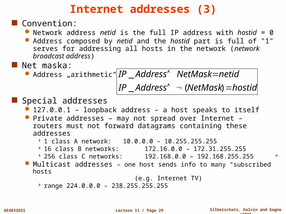
Internet addresses (3) Convention:
Network address netid is the full IP address with hostid = 0 Address composed by netid and the hostid part is full of "1" serves
for addressing all hosts in the network (network broadcast address) Net maska:
Address „arithmetic“
Special addresses 127.0.0.1 – loopback address – a host speaks to itself Private addresses – may not spread over Internet – routers must
not forward datagrams containing these addresses 1 class A network: 10.0.0.0 – 10.255.255.255 16 class B networks: 172.16.0.0 – 172.31.255.255 256 class C networks: 192.168.0.0 – 192.168.255.255
Multicast addresses – one host sends info to many “subscribed” hosts (e.g. Internet TV)
range 224.0.0.0 – 238.255.255.255
hostidNetMaskAddressIP
netidNetMaskAddressIP
)(_
_
Lecture 11 / Page 30 AE4B33OSS Silberschatz, Galvin and Gagne ©2005
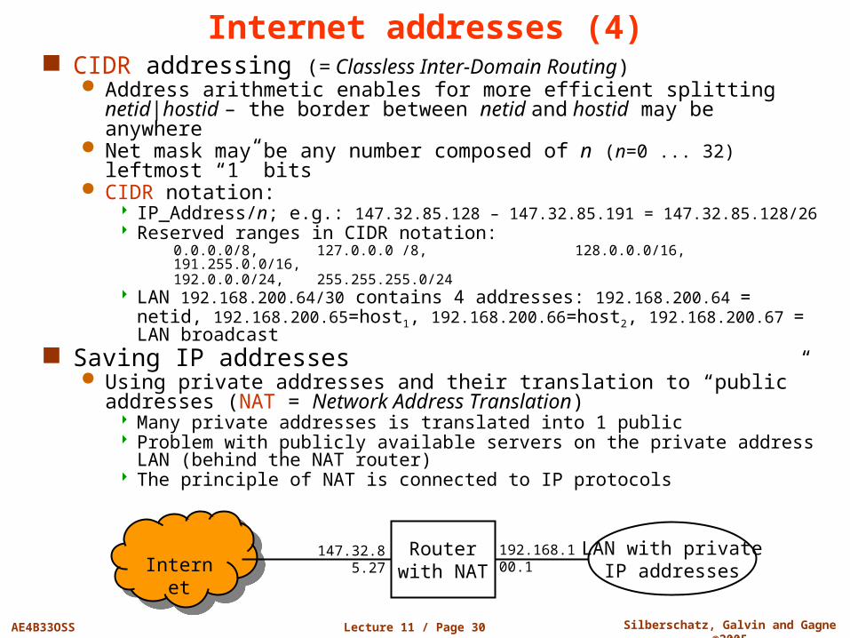
Internet addresses (4) CIDR addressing (= Classless Inter-Domain Routing)
Address arithmetic enables for more efficient splitting netid|hostid – the border between netid and hostid may be anywhere
Net mask may be any number composed of n (n=0 ... 32) leftmost “1” bits
CIDR notation: IP_Address/n; e.g.: 147.32.85.128 – 147.32.85.191 = 147.32.85.128/26 Reserved ranges in CIDR notation:
0.0.0.0/8, 127.0.0.0 /8, 128.0.0.0/16, 191.255.0.0/16,192.0.0.0/24, 255.255.255.0/24
LAN 192.168.200.64/30 contains 4 addresses: 192.168.200.64 = netid, 192.168.200.65=host1, 192.168.200.66=host2, 192.168.200.67 = LAN broadcast
Saving IP addresses Using private addresses and their translation to “public” addresses
(NAT = Network Address Translation) Many private addresses is translated into 1 public Problem with publicly available servers on the private address LAN
(behind the NAT router) The principle of NAT is connected to IP protocols
InternetInternetLAN with private
IP addressesRouter
with NAT147.32.85.27 192.168.100.1
Lecture 11 / Page 31 AE4B33OSS Silberschatz, Galvin and Gagne ©2005
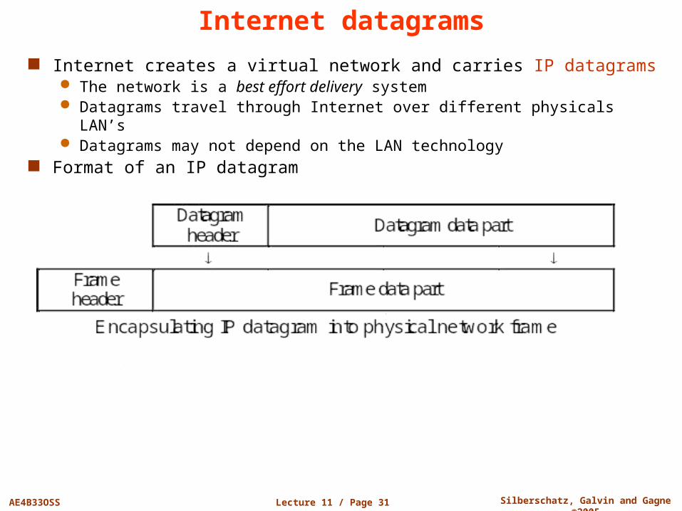
Internet datagrams
Internet creates a virtual network and carries IP datagrams The network is a best effort delivery system Datagrams travel through Internet over different physicals LAN’s Datagrams may not depend on the LAN technology
Format of an IP datagram
Lecture 11 / Page 32 AE4B33OSS Silberschatz, Galvin and Gagne ©2005
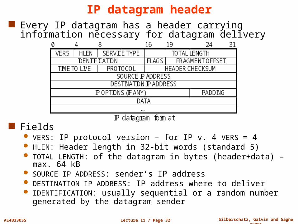
IP datagram header Every IP datagram has a header carrying information
necessary for datagram delivery
Fields VERS: IP protocol version – for IP v. 4 VERS = 4 HLEN: Header length in 32-bit words (standard 5) TOTAL LENGTH: of the datagram in bytes (header+data) – max. 64 kB SOURCE IP ADDRESS: sender’s IP address DESTINATION IP ADDRESS: IP address where to deliver IDENTIFICATION: usually sequential or a random number generated
by the datagram sender
Lecture 11 / Page 33 AE4B33OSS Silberschatz, Galvin and Gagne ©2005
IP datagram header (cont.)
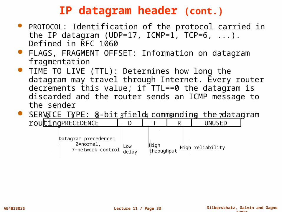
PROTOCOL: Identification of the protocol carried in the IP datagram (UDP=17, ICMP=1, TCP=6, ...). Defined in RFC 1060
FLAGS, FRAGMENT OFFSET: Information on datagram fragmentation
TIME TO LIVE (TTL): Determines how long the datagram may travel through Internet. Every router decrements this value; if TTL==0 the datagram is discarded and the router sends an ICMP message to the sender
SERVICE TYPE: 8-bit field commanding the datagram routing
0 1 2 3 4 5 6 7 PRECEDENCE D T R UNUSED
Datagram precedence: 0=normal, 7=network control
Low delay
High throughput High reliability
Lecture 11 / Page 34 AE4B33OSS Silberschatz, Galvin and Gagne ©2005
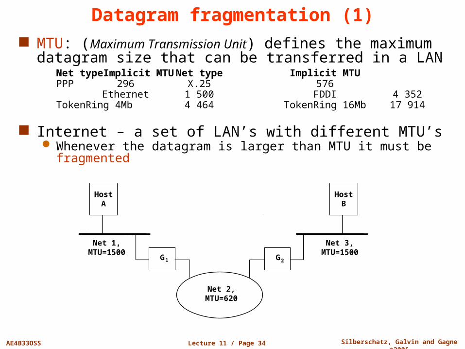
Datagram fragmentation (1) MTU: (Maximum Transmission Unit) defines the maximum
datagram size that can be transferred in a LANNet type Implicit MTU Net type Implicit
MTUPPP 296 X.25 576
Ethernet 1 500 FDDI 4 352TokenRing 4Mb 4 464 TokenRing 16Mb 17 914
Internet – a set of LAN’s with different MTU’s Whenever the datagram is larger than MTU it must be fragmented
HostB
Net 3,MTU=1500
HostA
Net 1,MTU=1500
Net 2,MTU=620
G1 G2
Lecture 11 / Page 35 AE4B33OSS Silberschatz, Galvin and Gagne ©2005
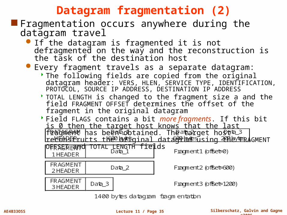
Datagram fragmentation (2) Fragmentation occurs anywhere during the datagram travel
If the datagram is fragmented it is not defragmented on the way and the reconstruction is the task of the destination host
Every fragment travels as a separate datagram: The following fields are copied from the original datagram header: VERS,
HLEN, SERVICE TYPE, IDENTIFICATION, PROTOCOL, SOURCE IP ADDRESS, DESTINATION IP ADDRESS
TOTAL LENGTH is changed to the fragment size a and the field FRAGMENT OFFSET determines the offset of the fragment in the original datagram
Field FLAGS contains a bit more fragments. If this bit is 0 then the target host knows that the last fragment has been obtained. The target host reconstructs the original datagram using the FRAGMENT OFFSET and TOTAL LENGTH fields

End of Lecture 11
Questions?