Embed Size (px)
Citation preview

Lecture 10 - State Machines, Von Neuman Architecture
Logistics- quiz 1 comes back Monday- Lab 3 due *Friday* night this week- Reminder: late work > 2 days will be given 0- Required reading posted: von Neumann’s original EDVAC report (1945!)
State Machines
We talked about sequential logic circuits before. These turn out to be very powerfulmechanisms for performing computationWe can generalize them a bit to the notion of a finite state machine (FSM)FSMs are abstract machines that have a finite state space. They transition betweenthese states and output values based on inputs to the machineSimplest finite state machine is called a recognizer. It only produces one bit of outputafter all the input is seen. It accepts the input if it outputs 1 (“yes”) and rejects theinput if it outputs 0 (“no”)For example, we can build a recognizer FSM that accepts all binary strings with atleast two 1s in them
Specifying State Machines
You need:A finite set of states (S)An input alphabet Σ (non-empty, finite set of symbols, e.g. {0,1})A start state (S0 ∈ S)A transition function (ẟ: S X Σ -> S). This function takes an input symbol and thecurrent state and outputs the new state.A set of accepting states A ⊆ S
A pseudocode implementation:
Init_state <- start state; while there is input left { input <- read a symbol; state <- ẟ(state, input); } if state ∈ A then output “Accept” (1) else output “Reject” (0) fi
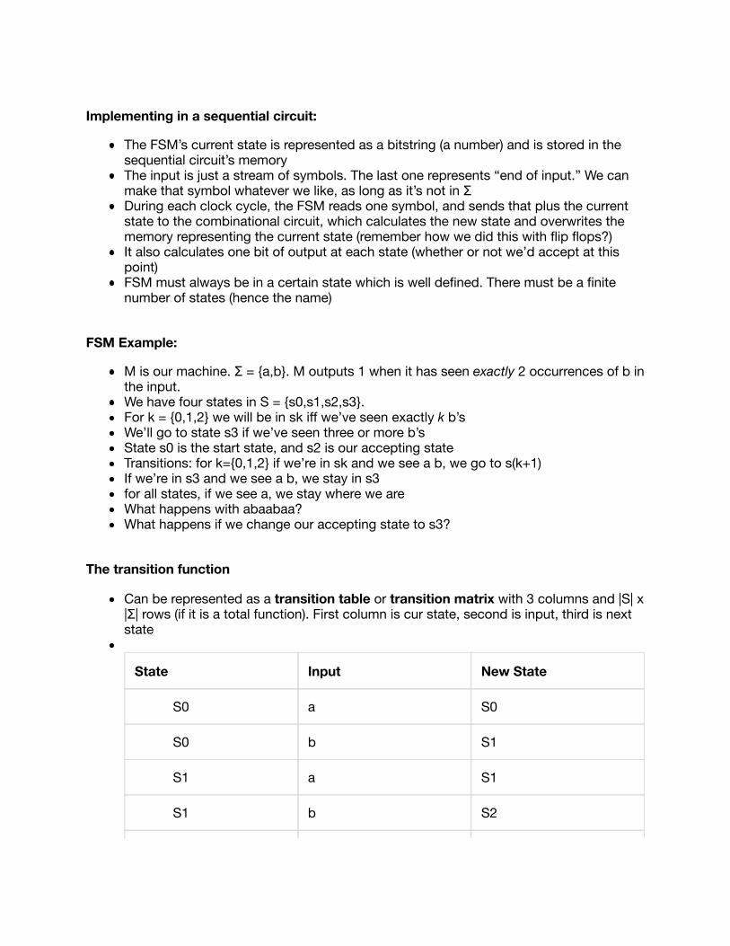
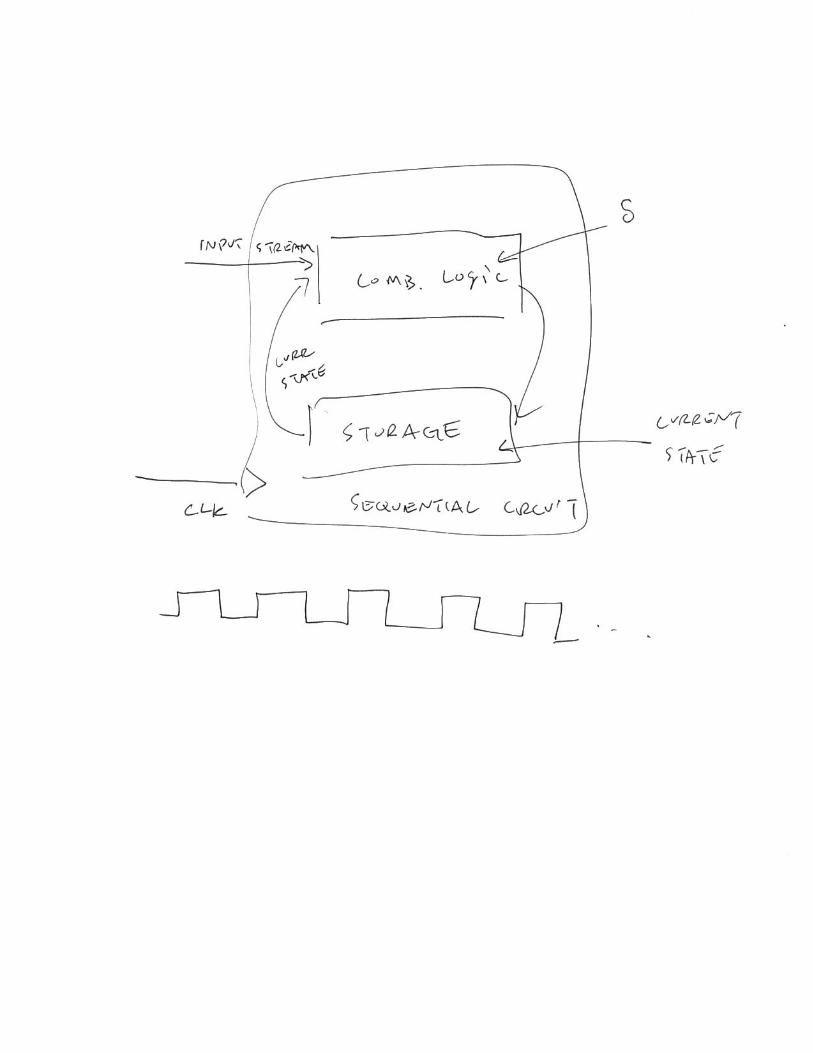
Implementing in a sequential circuit:
The FSM’s current state is represented as a bitstring (a number) and is stored in thesequential circuit’s memoryThe input is just a stream of symbols. The last one represents “end of input.” We canmake that symbol whatever we like, as long as it’s not in ΣDuring each clock cycle, the FSM reads one symbol, and sends that plus the currentstate to the combinational circuit, which calculates the new state and overwrites thememory representing the current state (remember how we did this with flip flops?)It also calculates one bit of output at each state (whether or not we’d accept at thispoint)FSM must always be in a certain state which is well defined. There must be a finitenumber of states (hence the name)
FSM Example:
M is our machine. Σ = {a,b}. M outputs 1 when it has seen exactly 2 occurrences of b inthe input. We have four states in S = {s0,s1,s2,s3}. For k = {0,1,2} we will be in sk iff we’ve seen exactly k b’sWe’ll go to state s3 if we’ve seen three or more b’sState s0 is the start state, and s2 is our accepting stateTransitions: for k={0,1,2} if we’re in sk and we see a b, we go to s(k+1)If we’re in s3 and we see a b, we stay in s3for all states, if we see a, we stay where we areWhat happens with abaabaa?What happens if we change our accepting state to s3?
The transition function
Can be represented as a transition table or transition matrix with 3 columns and |S| x|Σ| rows (if it is a total function). First column is cur state, second is input, third is nextstate
State Input New State
S0 a S0
S0 b S1
S1 a S1
S1 b S2

S2 a S2
S2 b S3
S3 a S3
S3 b S3
We can also use a state transition diagram, which is a directed graph. Circular nodesrepresent states, directed edges (arrows) representing transitions. We label the arrowswith input symbols. Accepting states are drawn with concentric circles
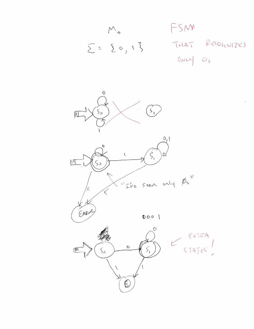
Another example: what would a machine look like that only accepts strings that havenothing but 0s?
Aside
What we’ve seen here is actually a model of computation, like TMs which we saw earlyonHowever, FSMs are more restricted that TMs (they aren’t as powerful computationallyspeaking)The “languages” that an FSM can recognize are much more restricted. In particular, anFSM can only recognize regular languages (those that don’t require memory whenrecognizing them)
The von Neumann computer
historically, the first computers were fixed program computersRecall the machines I walked you through in the first lecture. Many of those had hard-wired programsAnother way to put it is that they were not programmableThis clearly raises issues. We’d like our machines to be truly general purpose, in thatthe operations they perform can change over time

This led to the development of the stored program computer (or the von Neumanncomputer)In a von Neumann machine, programs (instructions for the computer) are stored inread/write memory along with data
Basic von Neumann architecture
A von Neumann architecture consists of three main parts: memory that is read/write,Input/output devices (I/O devices), and a central processing unit (CPU) which has thejob of actually executing instructions in the machinethe CPU consists of two primary subunits: the control and the processing unitThe simplest processing unit consists of an arithmetic logic unit (ALU), which performscalculations on data. Remember, we built a small ALU before!Which operations the ALU performs is determined by sequencing carried out by thecontrol unitA processing unit will also contain a register file, which is just a clump of registers usedfor temporary storage which the ALU can operate onThe ALU can get data from the control unit, and may send addresses to the controlunit for branches or jumps (control flow)Memory you can think of as a storage array and two primary registers, the MDR(memory data reg.) and the MAR (memory addr reg)MAR is k-bits wide (address width) and MDR is >= j bits, where j is the addressabilityof the machineWe also have I/O devices attached to the machine: e.g. keyboard, mouse, disk, video,printer, etc. They receive commands from the CPU. They can also send data andstatus back to the CPU. Device sends interrupt signals to the CPU to notify that it’sdone something