Embed Size (px)
Citation preview
BME Department of Mechanics, Materials and Structures Design of Reinforced Concrete Structures Introduction 1
BME Department of Mechanics, Materials and Structures
Lecture 1:
INTRODUCTION
BME Department of Mechanics, Materials and Structures Design of Reinforced Concrete Structures Introduction 2
CONTENT
1. Some executed examples of reinforced concrete (rc) structures of the latest period of time 2. What is rc? 3. Problems, possibilities, requirements 4. Phases of design 5. Mechanical behaviour of simple supported rc beams
6. Mechanical design
Cross-section design in ultimate limit state (ULS) of linear and planar members Check of the serviceability limit states (SLS)
BME Department of Mechanics, Materials and Structures Design of Reinforced Concrete Structures Introduction 3
7. Some historic concrete and reinforced concrete buildings 8. Developments in theory and construction 9. Requirements of the present
BME Department of Mechanics, Materials and Structures Design of Reinforced Concrete Structures Introduction 4
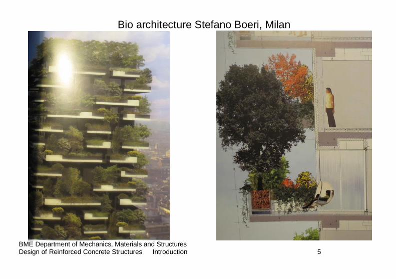
1. Some executed examples of the latest period of time
BME Department of Mechanics, Materials and Structures Design of Reinforced Concrete Structures Introduction 5
Bio architecture Stefano Boeri, Milan
BME Department of Mechanics, Materials and Structures Design of Reinforced Concrete Structures Introduction 6
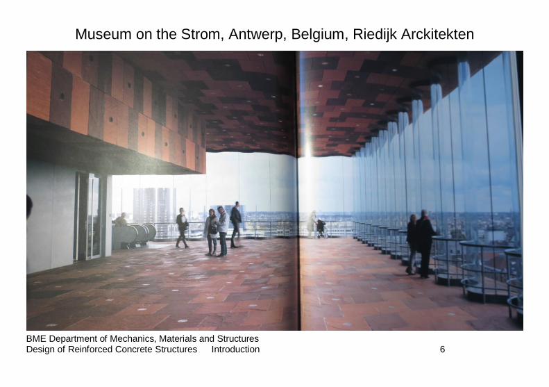
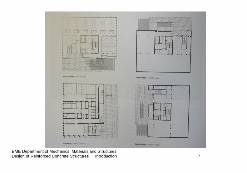
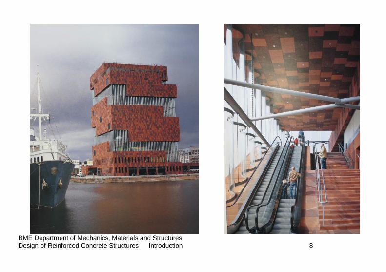
Museum on the Strom, Antwerp, Belgium, Riedijk Arckitekten
BME Department of Mechanics, Materials and Structures Design of Reinforced Concrete Structures Introduction 7
BME Department of Mechanics, Materials and Structures Design of Reinforced Concrete Structures Introduction 8
BME Department of Mechanics, Materials and Structures Design of Reinforced Concrete Structures Introduction 9
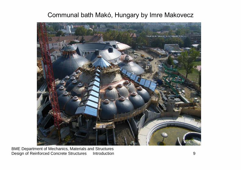
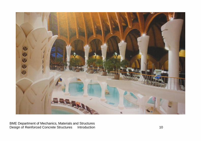
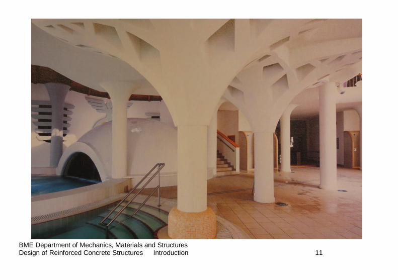
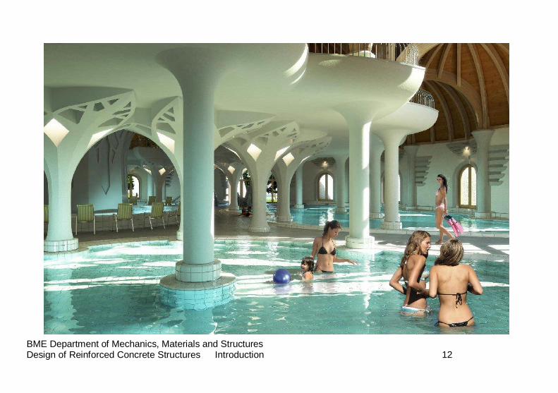
Communal bath Makó, Hungary by Imre Makovecz
BME Department of Mechanics, Materials and Structures Design of Reinforced Concrete Structures Introduction 10
BME Department of Mechanics, Materials and Structures Design of Reinforced Concrete Structures Introduction 11
BME Department of Mechanics, Materials and Structures Design of Reinforced Concrete Structures Introduction 12
BME Department of Mechanics, Materials and Structures Design of Reinforced Concrete Structures Introduction 13
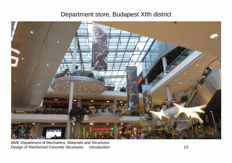
Department store, Budapest XIth district
BME Department of Mechanics, Materials and Structures Design of Reinforced Concrete Structures Introduction 14
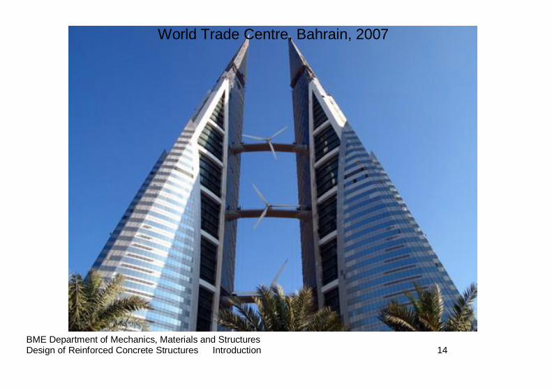
World Trade Centre, Bahrain, 2007
BME Department of Mechanics, Materials and Structures Design of Reinforced Concrete Structures Introduction 15
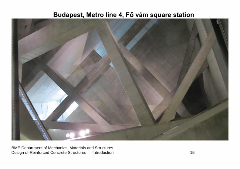
Budapest, Metro line 4, Fő vám square station
BME Department of Mechanics, Materials and Structures Design of Reinforced Concrete Structures Introduction 16
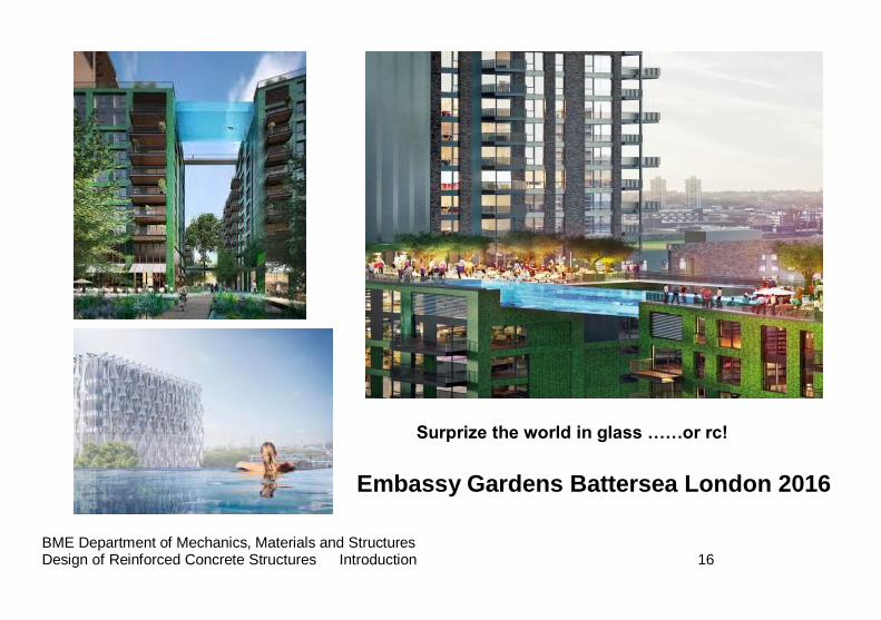
Surprize the world in glass ……or rc!
Embassy Gardens Battersea London 2016
BME Department of Mechanics, Materials and Structures Design of Reinforced Concrete Structures Introduction 17
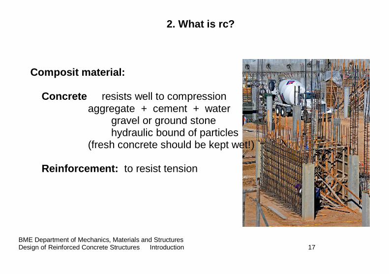
2. What is rc?
Composit material:
Concrete resists well to compression aggregate + cement + water
gravel or ground stone hydraulic bound of particles (fresh concrete should be kept wet!)
Reinforcement: to resist tension
BME Department of Mechanics, Materials and Structures Design of Reinforced Concrete Structures Introduction 18
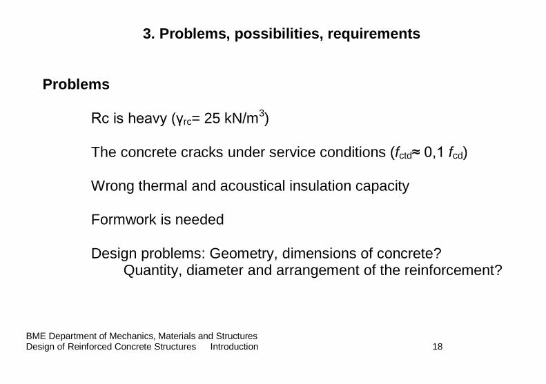
3. Problems, possibilities, requirements Problems Rc is heavy (γrc= 25 kN/m3) The concrete cracks under service conditions (fctd≈ 0,1 fcd) Wrong thermal and acoustical insulation capacity Formwork is needed Design problems: Geometry, dimensions of concrete?
Quantity, diameter and arrangement of the reinforcement?
BME Department of Mechanics, Materials and Structures Design of Reinforced Concrete Structures Introduction 19
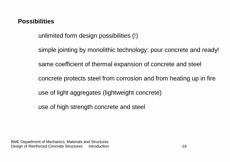
Possibilities unlimited form design possibilities (!) simple jointing by monolithic technology: pour concrete and ready! same coefficient of thermal expansion of concrete and steel
concrete protects steel from corrosion and from heating up in fire
use of light aggregates (lightweight concrete) use of high strength concrete and steel
BME Department of Mechanics, Materials and Structures Design of Reinforced Concrete Structures Introduction 20
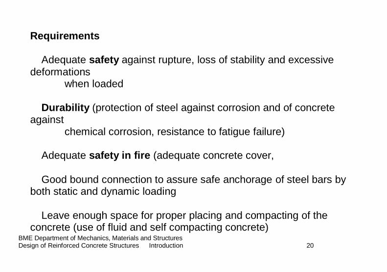
Requirements Adequate safety against rupture, loss of stability and excessive deformations when loaded Durability (protection of steel against corrosion and of concrete against chemical corrosion, resistance to fatigue failure) Adequate safety in fire (adequate concrete cover,
Good bound connection to assure safe anchorage of steel bars by both static and dynamic loading Leave enough space for proper placing and compacting of the concrete (use of fluid and self compacting concrete)
BME Department of Mechanics, Materials and Structures Design of Reinforced Concrete Structures Introduction 21
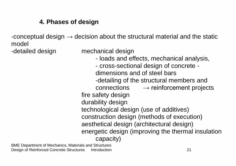
4. Phases of design
-conceptual design → decision about the structural material and the static model -detailed design mechanical design
- loads and effects, mechanical analysis, - cross-sectional design of concrete - dimensions and of steel bars -detailing of the structural members and connections → reinforcement projects
fire safety design durability design technological design (use of additives) construction design (methods of execution) aesthetical design (architectural design) energetic design (improving the thermal insulation capacity)
BME Department of Mechanics, Materials and Structures Design of Reinforced Concrete Structures Introduction 22
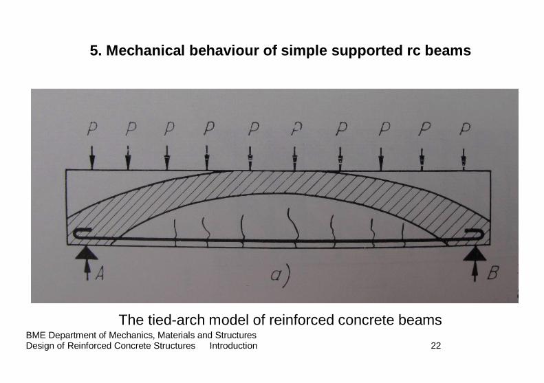
5. Mechanical behaviour of simple supported rc beams
The tied-arch model of reinforced concrete beams
BME Department of Mechanics, Materials and Structures Design of Reinforced Concrete Structures Introduction 23
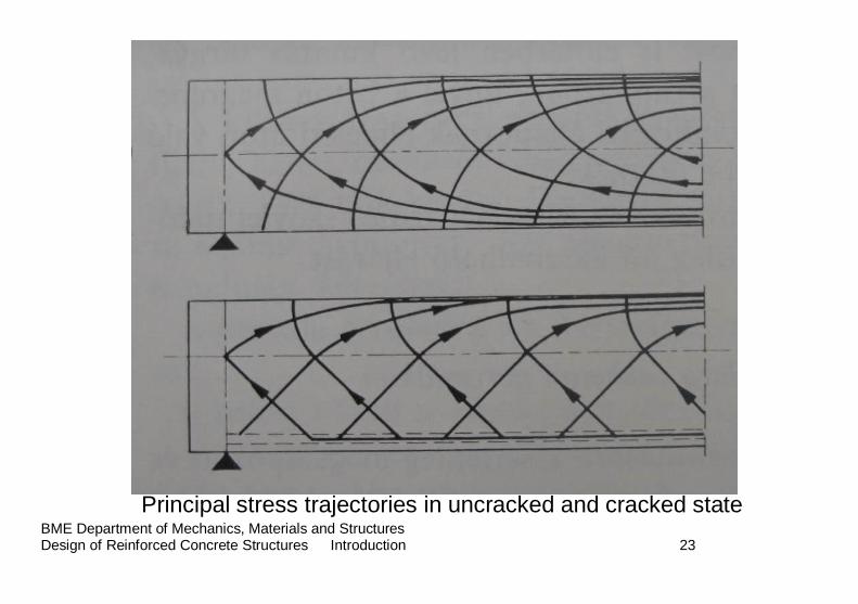
Principal stress trajectories in uncracked and cracked state
BME Department of Mechanics, Materials and Structures Design of Reinforced Concrete Structures Introduction 24
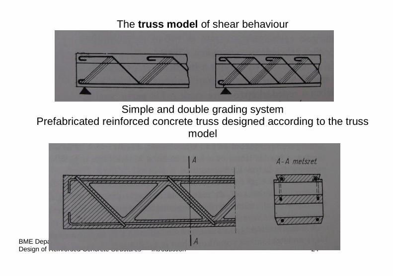
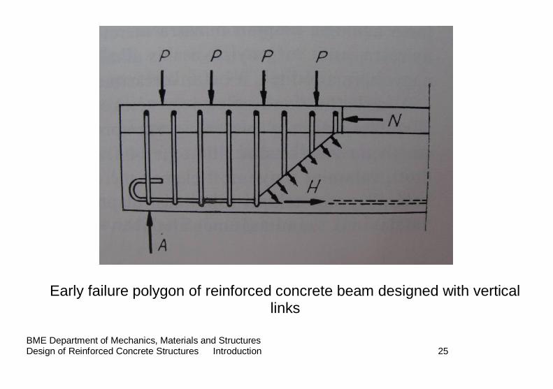
The truss model of shear behaviour
Simple and double grading system Prefabricated reinforced concrete truss designed according to the truss
model
BME Department of Mechanics, Materials and Structures Design of Reinforced Concrete Structures Introduction 25
Early failure polygon of reinforced concrete beam designed with vertical links
BME Department of Mechanics, Materials and Structures Design of Reinforced Concrete Structures Introduction 26
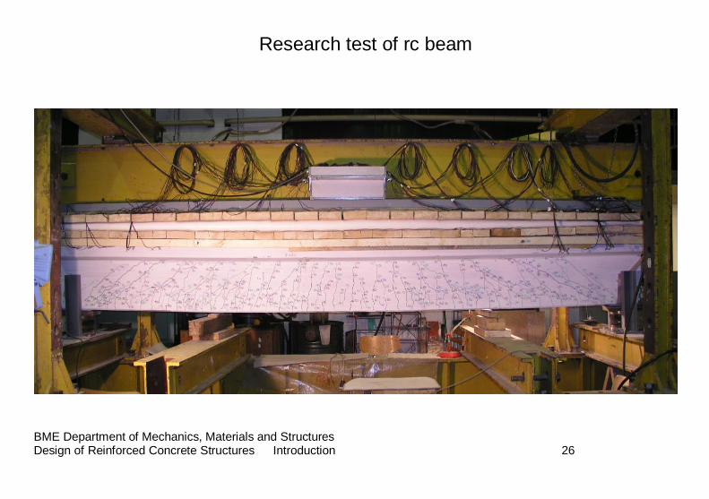
Research test of rc beam
BME Department of Mechanics, Materials and Structures Design of Reinforced Concrete Structures Introduction 27
6. Mechanical design
BME Department of Mechanics, Materials and Structures Design of Reinforced Concrete Structures Introduction 28
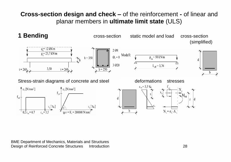
Cross-section design and check – of the reinforcement - of linear and planar members in ultimate limit state (ULS)
1 Bending cross-section static model and load cross-section
(simplified)
Stress-strain diagrams of concrete and steel deformations stresses
BME Department of Mechanics, Materials and Structures Design of Reinforced Concrete Structures Introduction 29
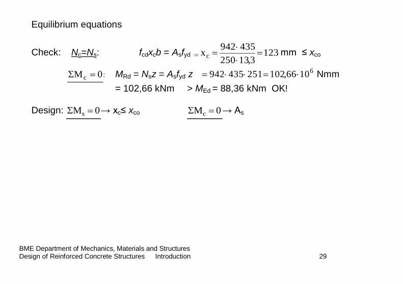
Equilibrium equations
Check: Nc=Ns: fcdxcb = Asfyd 1233,13250
435942xc
mm ≤ xco
0Mc : MRd = Nsz = Asfyd z 61066,102251435942 Nmm
= 102,66 kNm > MEd = 88,36 kNm OK! Design: 0Ms → xc≤ xco 0Mc → As
BME Department of Mechanics, Materials and Structures Design of Reinforced Concrete Structures Introduction 30
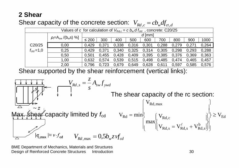
2 Shear
Shear capacity of the concrete section: dctwcRd dfcbV ,, Values of c for calculation of VRd,c = c bw d fctd , concrete: C20/25
ρl=Asw /(bws) %]
d [mm]
≤ 200 300 400 500 600 700 800 900 1000
C20/25 0,00 0,429 0,371 0,338 0,316 0,301 0,288 0,279 0,271 0,264
fctd =1,0 0,25 0,429 0,371 0,340 0,325 0,314 0,305 0,298 0,293 0,288
0,50 0,501 0,455 0,428 0,409 0,395 0,385 0,376 0,369 0,363
1,00 0,632 0,574 0,539 0,515 0,498 0,485 0,474 0,465 0,457
2,00 0,796 0,723 0,679 0,649 0,628 0,611 0,597 0,585 0,576
Shear supported by the shear reinforcement (vertical links):
ywdswsRd fAs
zV ,
The shear capacity of the rc section:
Max. shear capacity limited by fcd Ed
bs,Rds,Rds,Rd
c,Rd
max,Rd
Rd V
VVV
Vmax
V
minV
cdwRd fzbV 5,0max,
BME Department of Mechanics, Materials and Structures Design of Reinforced Concrete Structures Introduction 31
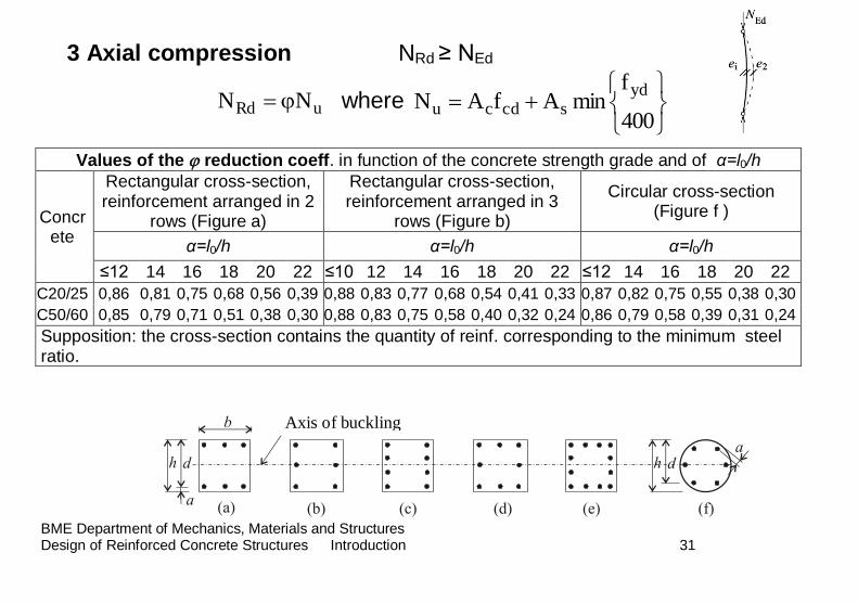
3 Axial compression NRd ≥ NEd
uRd NN where
400
fminAfAN
ydscdcu
Values of the reduction coeff. in function of the concrete strength grade and of α=l0/h
Concrete
Rectangular cross-section, reinforcement arranged in 2
rows (Figure a)
Rectangular cross-section, reinforcement arranged in 3
rows (Figure b)
Circular cross-section (Figure f )
α=l0/h α=l0/h α=l0/h
≤12 14 16 18 20 22 ≤10 12 14 16 18 20 22 ≤12 14 16 18 20 22
C20/25 0,86 0,81 0,75 0,68 0,56 0,39 0,88 0,83 0,77 0,68 0,54 0,41 0,33 0,87 0,82 0,75 0,55 0,38 0,30
C50/60 0,85 0,79 0,71 0,51 0,38 0,30 0,88 0,83 0,75 0,58 0,40 0,32 0,24 0,86 0,79 0,58 0,39 0,31 0,24
Supposition: the cross-section contains the quantity of reinf. corresponding to the minimum steel ratio.
Axis of buckling
BME Department of Mechanics, Materials and Structures Design of Reinforced Concrete Structures Introduction 32
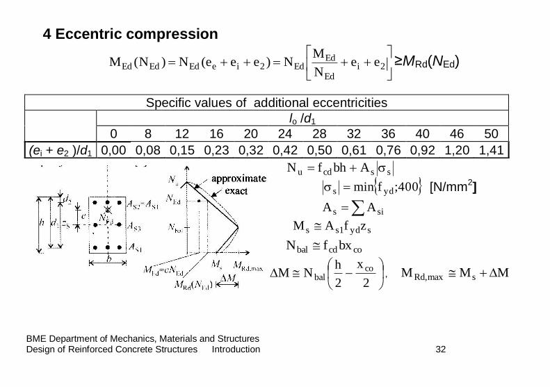
4 Eccentric compression
2i
Ed
EdEd2ieEdEdEd ee
N
MN)eee(N)N(M ≥MRd(NEd)
sscdu AbhfN
400;fmin yds [N/mm2]
sis AA
syds1s zfAM
cocdbal bxfN
2
x
2
hNM co
bal , MMM smaxRd,
Specific values of additional eccentricities
lo /d1
0 8 12 16 20 24 28 32 36 40 46 50
(ei + e2 )/d1 0,00 0,08 0,15 0,23 0,32 0,42 0,50 0,61 0,76 0,92 1,20 1,41
BME Department of Mechanics, Materials and Structures Design of Reinforced Concrete Structures Introduction 33
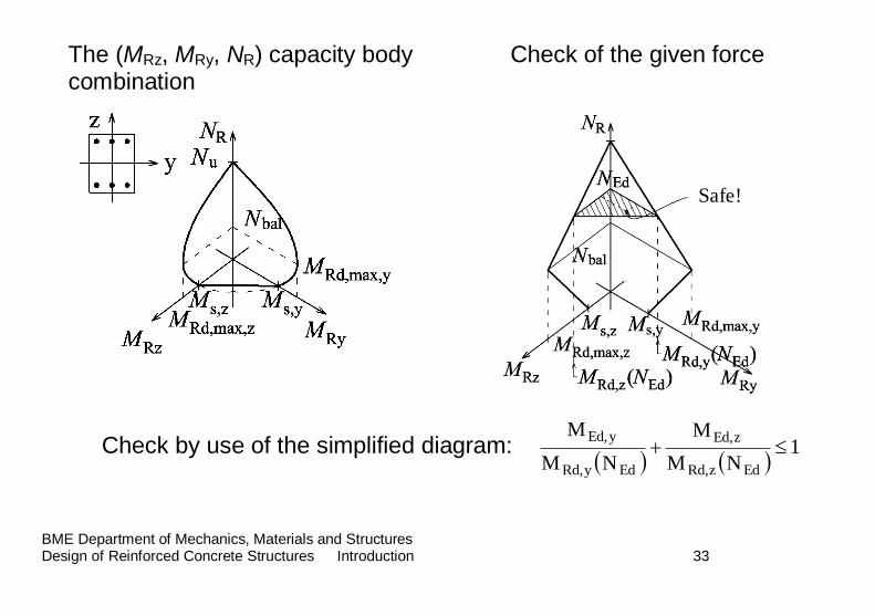
The (MRz, MRy, NR) capacity body Check of the given force combination
Check by use of the simplified diagram:
1NM
M
NM
M
EdzRd,
zEd,
EdyRd,
yEd,
Safe!
BME Department of Mechanics, Materials and Structures Design of Reinforced Concrete Structures Introduction 34
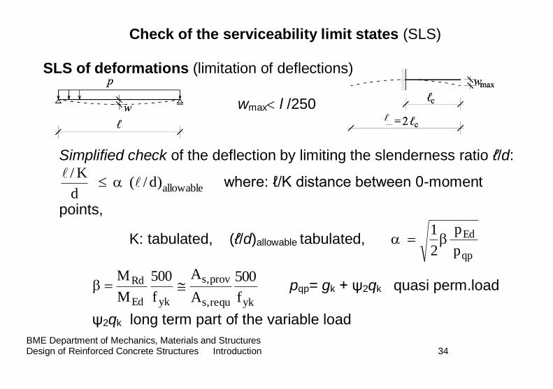
Check of the serviceability limit states (SLS)
SLS of deformations (limitation of deflections)
wmax l /250
Simplified check of the deflection by limiting the slenderness ratio ℓ/d:
allowable)d/( d
K/
where: ℓ/K distance between 0-moment
points,
K: tabulated, (ℓ/d)allowable tabulated, qp
Ed
p
p
2
1
ykEd
Rd
f
500
M
M
ykrequ,s
prov,s
f
500
A
A pqp= gk + ψ2qk quasi perm.load
ψ2qk long term part of the variable load
ℓ
BME Department of Mechanics, Materials and Structures Design of Reinforced Concrete Structures Introduction 35
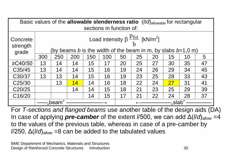
Basic values of the allowable slenderness ratio (l/d)allowable for rectangular
sections in function of:
Concrete strength grade
Load intensity b
pEd [kN/m2]
(by beams b is the width of the beam in m, by slabs b=1,0 m)
300 250 200 150 100 50 25 20 15 10 5
≥C40/50 13 14 14 15 17 20 25 27 30 35 47
C35/45 13 14 14 15 16 19 24 26 29 34 45
C30/37 13 13 14 15 16 19 23 25 28 33 43
C25/30 13 14 14 16 18 22 24 27 31 41
C20/25 14 14 15 18 21 23 25 29 39
C16/20 14 15 17 21 22 24 28 37
――„beam” ―――――――→ ←――――――„slab” ―――――
For T-sections and flanged beams use another table of the design aids (DA) In case of applying pre-camber of the extent l/500, we can add Δ(l/d)allow =4 to the values of the previous table, whereas in case of a pre-camber by l/250, Δ(l/d)allow =8 can be added to the tabulated values
BME Department of Mechanics, Materials and Structures Design of Reinforced Concrete Structures Introduction 36
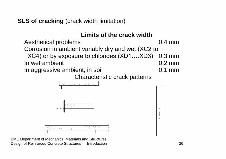
SLS of cracking (crack width limitation)
Limits of the crack width
Aesthetical problems 0,4 mm Corrosion in ambient variably dry and wet (XC2 to XC4) or by exposure to chlorides (XD1….XD3) 0,3 mm
In wet ambient 0,2 mm In aggressive ambient, in soil 0,1 mm
Characteristic crack patterns
BME Department of Mechanics, Materials and Structures Design of Reinforced Concrete Structures Introduction 37 provs,
reqs,
Ed
qpyds
A
A
p
pf
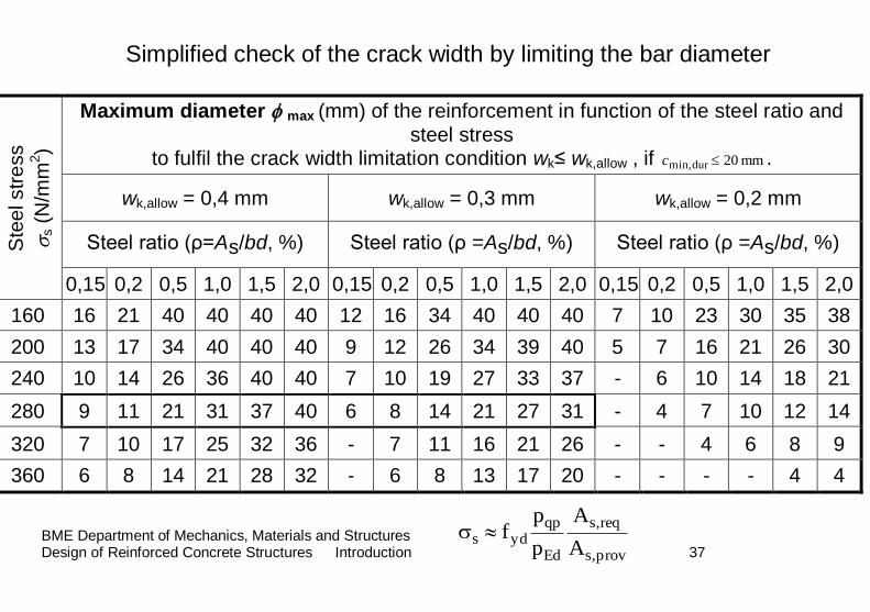
Simplified check of the crack width by limiting the bar diameter
Ste
el str
ess
s (
N/m
m2)
Maximum diameter max (mm) of the reinforcement in function of the steel ratio and steel stress
to fulfil the crack width limitation condition wk≤ wk,allow , if mm 20min,dur c .
wk,allow = 0,4 mm wk,allow = 0,3 mm wk,allow = 0,2 mm
Steel ratio (ρ=As/bd, %) Steel ratio (ρ =As/bd, %) Steel ratio (ρ =As/bd, %)
0,15 0,2 0,5 1,0 1,5 2,0 0,15 0,2 0,5 1,0 1,5 2,0 0,15 0,2 0,5 1,0 1,5 2,0
160 16 21 40 40 40 40 12 16 34 40 40 40 7 10 23 30 35 38
200 13 17 34 40 40 40 9 12 26 34 39 40 5 7 16 21 26 30
240 10 14 26 36 40 40 7 10 19 27 33 37 - 6 10 14 18 21
280 9 11 21 31 37 40 6 8 14 21 27 31 - 4 7 10 12 14
320 7 10 17 25 32 36 - 7 11 16 21 26 - - 4 6 8 9
360 6 8 14 21 28 32 - 6 8 13 17 20 - - - - 4 4
BME Department of Mechanics, Materials and Structures Design of Reinforced Concrete Structures Introduction 38
7. Some historic concrete and reinforced concrete buildings
BME Department of Mechanics, Materials and Structures Design of Reinforced Concrete Structures Introduction 39
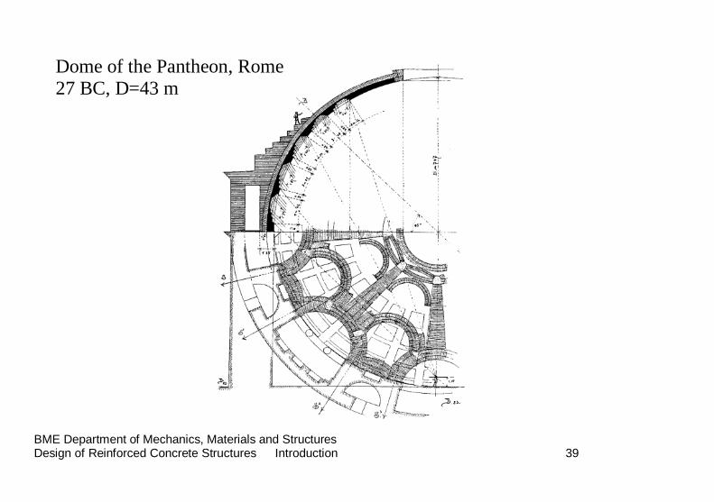
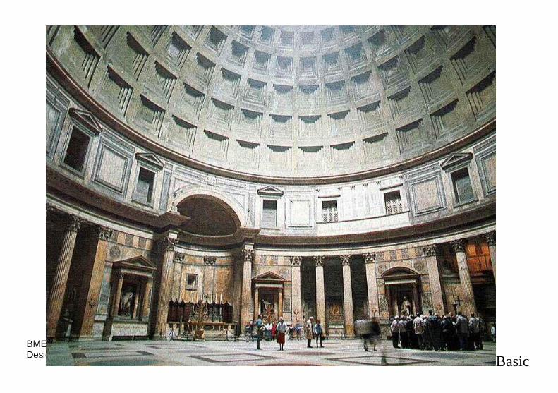
Dome of the Pantheon, Rome 27 BC, D=43 m
BME Department of Mechanics, Materials and Structures Design of Reinforced Concrete Structures Introduction 40
Basic
BME Department of Mechanics, Materials and Structures Design of Reinforced Concrete Structures Introduction 41
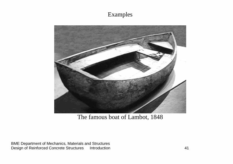
Examples
The famous boat of Lambot, 1848
BME Department of Mechanics, Materials and Structures Design of Reinforced Concrete Structures Introduction 42
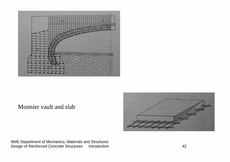
Monnier vault and slab
BME Department of Mechanics, Materials and Structures Design of Reinforced Concrete Structures Introduction 43
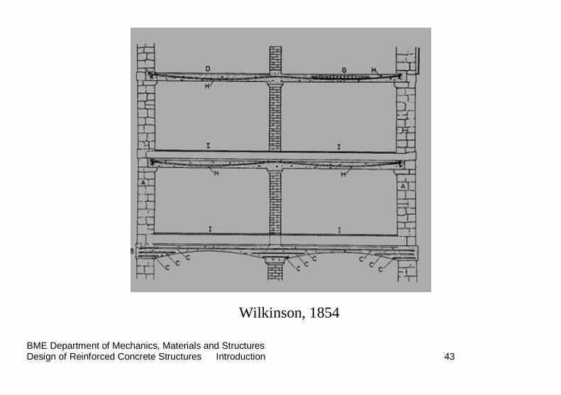
Wilkinson, 1854
BME Department of Mechanics, Materials and Structures Design of Reinforced Concrete Structures Introduction 44
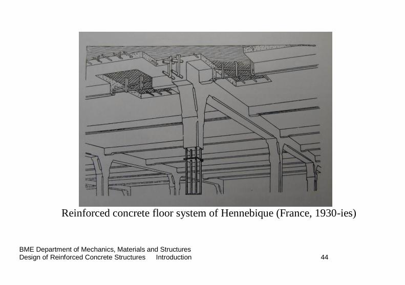
Reinforced concrete floor system of Hennebique (France, 1930-ies)
BME Department of Mechanics, Materials and Structures Design of Reinforced Concrete Structures Introduction 45
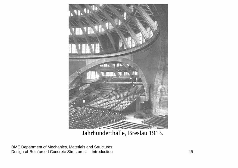
Jahrhunderthalle, Breslau 1913.
BME Department of Mechanics, Materials and Structures Design of Reinforced Concrete Structures Introduction 46
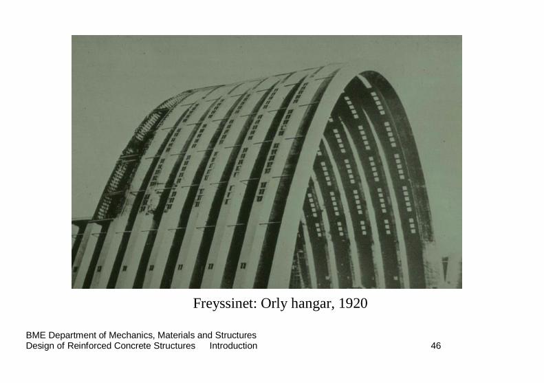
Freyssinet: Orly hangar, 1920
BME Department of Mechanics, Materials and Structures Design of Reinforced Concrete Structures Introduction 47
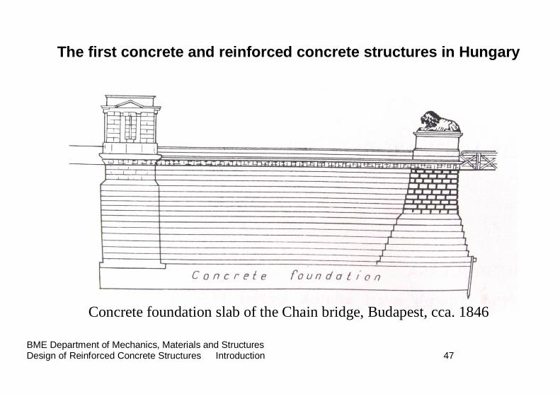
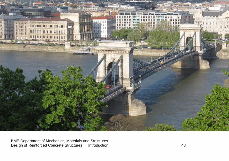
The first concrete and reinforced concrete structures in Hungary
Concrete foundation slab of the Chain bridge, Budapest, cca. 1846
BME Department of Mechanics, Materials and Structures Design of Reinforced Concrete Structures Introduction 48
BME Department of Mechanics, Materials and Structures Design of Reinforced Concrete Structures Introduction 49
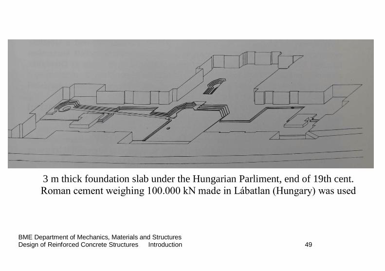
3 m thick foundation slab under the Hungarian Parliment, end of 19th cent. Roman cement weighing 100.000 kN made in Lábatlan (Hungary) was used

BME Department of Mechanics, Materials and Structures Design of Reinforced Concrete Structures Introduction 50
BME Department of Mechanics, Materials and Structures Design of Reinforced Concrete Structures Introduction 51
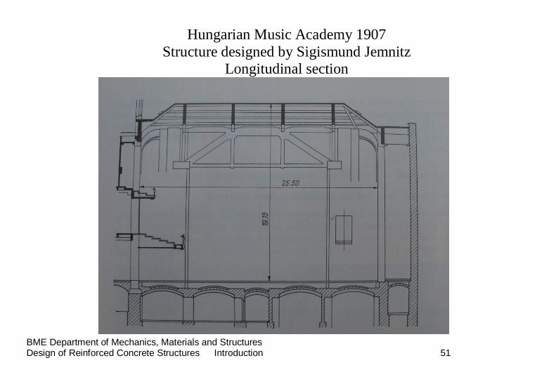
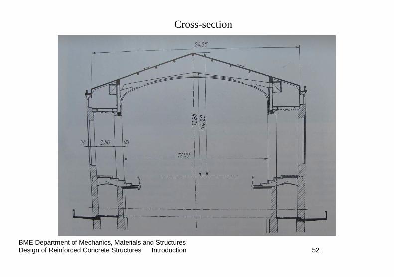
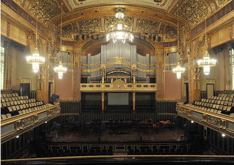
Hungarian Music Academy 1907
Structure designed by Sigismund Jemnitz Longitudinal section
BME Department of Mechanics, Materials and Structures Design of Reinforced Concrete Structures Introduction 52
Cross-section
BME Department of Mechanics, Materials and Structures Design of Reinforced Concrete Structures Introduction 53
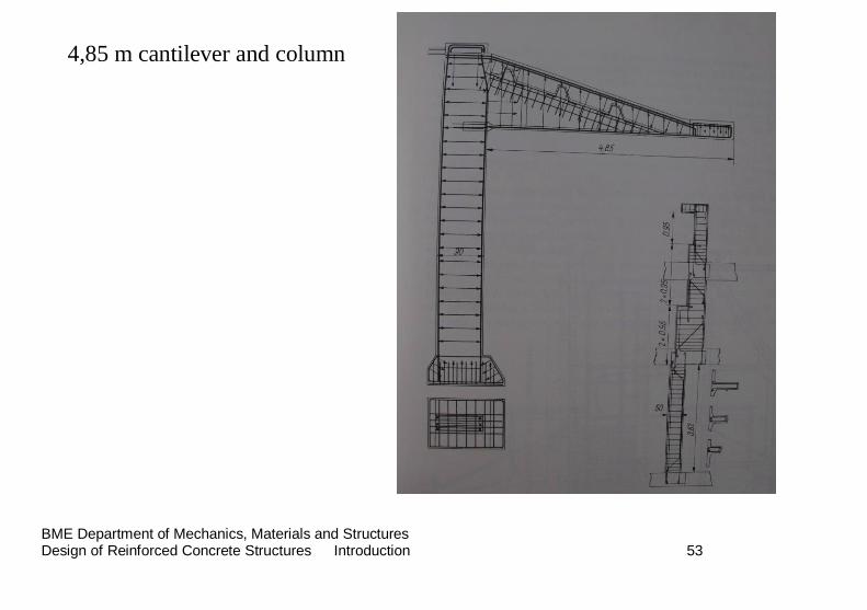
4,85 m cantilever and column
BME Department of Mechanics, Materials and Structures Design of Reinforced Concrete Structures Introduction 54
BME Department of Mechanics, Materials and Structures Design of Reinforced Concrete Structures Introduction 55
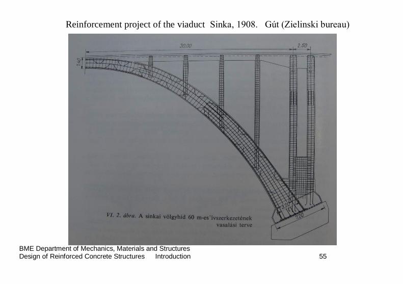
Reinforcement project of the viaduct Sinka, 1908. Gút (Zielinski bureau)
BME Department of Mechanics, Materials and Structures Design of Reinforced Concrete Structures Introduction 56
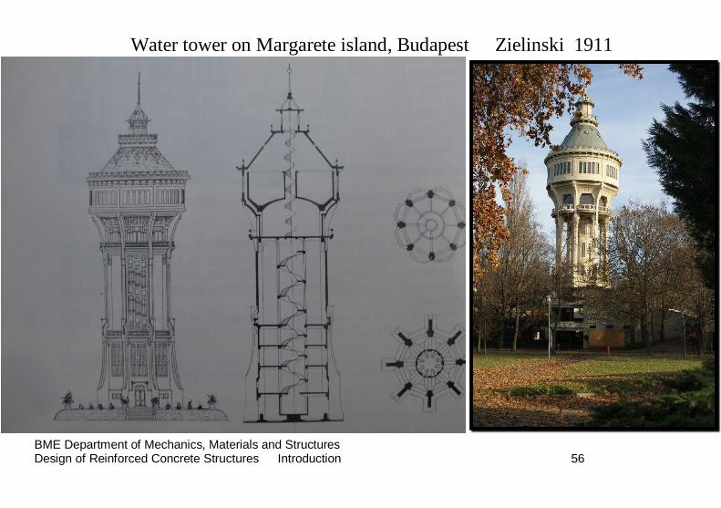
Water tower on Margarete island, Budapest Zielinski 1911
BME Department of Mechanics, Materials and Structures Design of Reinforced Concrete Structures Introduction 57
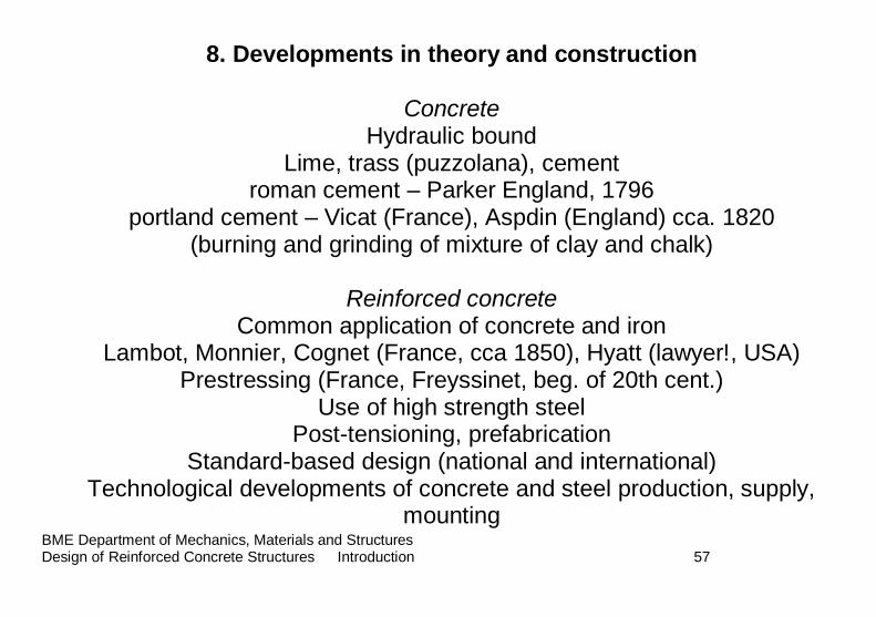
8. Developments in theory and construction
Concrete Hydraulic bound
Lime, trass (puzzolana), cement roman cement – Parker England, 1796
portland cement – Vicat (France), Aspdin (England) cca. 1820 (burning and grinding of mixture of clay and chalk)
Reinforced concrete
Common application of concrete and iron Lambot, Monnier, Cognet (France, cca 1850), Hyatt (lawyer!, USA)
Prestressing (France, Freyssinet, beg. of 20th cent.) Use of high strength steel
Post-tensioning, prefabrication Standard-based design (national and international)
Technological developments of concrete and steel production, supply, mounting
BME Department of Mechanics, Materials and Structures Design of Reinforced Concrete Structures Introduction 58
9. Requirements of the present
Beside traditional requirements formulated for the ULS and SLS, development in
-design philosophy and structural analysis -production technology of concrete and steel
-realization technology of structures result in new, more and more detailed requirements to be fulfilled by
design, like for example:
-durability requirements
-verification of safety against accidental loads, like fire, earthquake, blasting
-fulfilment - by loadbearing structural members – of traditional requirements of building constructions, like:
-watertight behaviour, heat insulation, acoustic insulation, reduction of the self-weight, frost-resistance, workability
BME Department of Mechanics, Materials and Structures Design of Reinforced Concrete Structures Introduction 59
Way of checking and/or fulfilling these requirements will be treated during the course
END OF LECTURE 1