Embed Size (px)
Citation preview

1
Lect 34

2Prof. Bhaskar Roy, Prof. A M Pradeep, Department of Aerospace, IIT Bombay
Lect 34
Centrifugal Compressors
Design of Centrifugal Compressor elements – Impellers, Vanes etc.

3Prof. Bhaskar Roy, Prof. A M Pradeep, Department of Aerospace, IIT Bombay
Lect 34
a) Impellerb) Diffuser
Vanesc) Vaneless
diffusere) Inlet Guide
vanesf) Volute

4Prof. Bhaskar Roy, Prof. A M Pradeep, Department of Aerospace, IIT Bombay
Lect 34
Other Design Possibilities: a) Double-sided impeller :
b) Multi-staged compressor
5Prof. Bhaskar Roy, Prof. A M Pradeep, Department of Aerospace, IIT Bombay
Lect 34
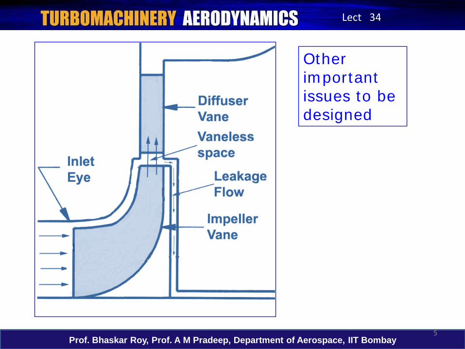
Other important issues to be designed
6Prof. Bhaskar Roy, Prof. A M Pradeep, Department of Aerospace, IIT Bombay
Lect 34
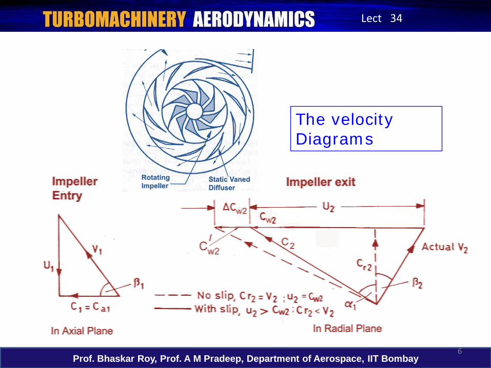
The velocity Diagrams

7Prof. Bhaskar Roy, Prof. A M Pradeep, Department of Aerospace, IIT Bombay
Lect 34
Slip factorIn a real compressor relative velocity vector V2 is at angle β2 because of non-radial exit from the impeller tip as the real viscous flow detaches near the tip from the impeller vane (trailing) surface
φs *2 2
0.63.π / Nσ = 1 - 1- . tanβ
s0.63.πσ = 1-
N
Stanitz formula ,
which, for a radial vane,
φ 2r2
2
C=
U
2
2r2
cosβ )/ (1σ )/U(V1
)/(1σ
N
Nπ
π
−=−
−=2
2
tanβcosβ
Wisner’s definition
Stodola Definition
Where & N= no. of blades
No dependence on backsweep
β2 <-450 ; N>8
β2 >-450 ; N>20
00 < β2 <-600

8Prof. Bhaskar Roy, Prof. A M Pradeep, Department of Aerospace, IIT Bombay
Lect 34
Forward Curved Vanes
Small Volume
High Pressure ratio
High speedHigh noise , Low Efficiency
Backward curved Vanes
Large Volume and size
Low to High Pr Ratio
High Efficiency, Low Noise
Radial Vanes Medium Volume and Size
Medium to High Pr ratio
Good Efficiency
Radial Vaned CCs have been used in A/C engines for 50 years. Now, well designed backward curved vaned CCs are increasingly being used for higher efficiency.

9Prof. Bhaskar Roy, Prof. A M Pradeep, Department of Aerospace, IIT Bombay
Lect 34
In highly forward and highly backward curved (β2 >-600 ) impellers slip factor looses its meaning

10Prof. Bhaskar Roy, Prof. A M Pradeep, Department of Aerospace, IIT Bombay
Lect 34
At the compr. entry face
a11
1
Ctanβ =U
U1 = ω.reye where reye varies from the root to the tip of the eye
Thus for a high speed compressor (or large sized) β1 shall vary hugely from root to tip of the eye.
Under off-design operations, at any radius, incidence, ir
( )*r 1 1 ri =β -β
High positive incidence i (≥ +50) may precipitate early flow separation inside the impeller vane passage, even near the eye, specially if high diffusion (i.e. high adverse pressure gradient) is being attempted inside the impeller vanes.
To be decided by designer

11Prof. Bhaskar Roy, Prof. A M Pradeep, Department of Aerospace, IIT Bombay
Lect 34
At the exit plane of the impeller, the exiting flow deviates from the trailing edge and lag behind in rotational mode. This is often referred to as the lag or deviation angle.
*av 2 2δ= β- β
which is an average at the passage exit, and β2* is the impeller vane exit angle set by design
Diffusion Limit :
An upper limit of realistic diffusion limit V2/V1≈ 0.6In rotating diffuser V2/V1 < 0.6In Impeller design, ρ1 A1 / ρ2 A2 > 2.0

12Prof. Bhaskar Roy, Prof. A M Pradeep, Department of Aerospace, IIT Bombay
Lect 34
Design of the vaneless space
• Vaneless space is often used to decelerate impeller exit flow from supersonic to subsonic speed
• A completely vaneless diffuser is lighter , has broader mass flow operating range but has a lower efficiency

13Prof. Bhaskar Roy, Prof. A M Pradeep, Department of Aerospace, IIT Bombay
Lect 34
Backward curved vanes + splitter
Reduction in deviation angle at the impeller exit under off-design operating conditions is to be designed in to the impeller and the vane designs.
Vaneless diffuser

14Prof. Bhaskar Roy, Prof. A M Pradeep, Department of Aerospace, IIT Bombay
Lect 34
.( -1). ) = 1 + 0c0C
γγ-1η γπ
=
203 s 2 1 w1
201 01
pΨ. (σ . U -U .Cp a
The general relationship for Compressor Pressure ratio is given by
• Theoretical energy density (Hth) transfer is highest with forward curved vanes, in which most of the energy would be available in kinetic form, Hdyn at the impeller exit.
• While a radial impeller gives almost 50-50 split of static (Hstatic ) and dynamic heads (Hdyn) at the impeller exit, the backward curved vanes give high static pressure development in the impeller.
• Pre-swirl ( α1 > 0 ) reduces the work done by compressor

15Prof. Bhaskar Roy, Prof. A M Pradeep, Department of Aerospace, IIT Bombay
Lect 34
With Mass Flow Control only
The theoretically obtained points to the right of b are considered choked, i.e. the compressor cannot process greater mass flows. The compressor is said to go in to stall at , this happens when high pressure rise is attempted at low mass flow
am

16Prof. Bhaskar Roy, Prof. A M Pradeep, Department of Aerospace, IIT Bombay
Lect 34
With Speed Control and Flow Control
• In aircraft engines, rotating speed is variable during actual running.
•Thus the zone of operation is bounded between the points a,b,c and d .
•The ηmin lines and the speed lines, nmaxand nmin, define the boundaries (shaded area) of operation.

17Prof. Bhaskar Roy, Prof. A M Pradeep, Department of Aerospace, IIT Bombay
Lect 34
• If more control variables are available it maybe possible to extend the zone of operation ofthe compressor. All possible means of extendingthese boundaries further are being explored.
• Variable geometry (stagger) Inlet and exit (diffuser) guide vanes to be explored

18Prof. Bhaskar Roy, Prof. A M Pradeep, Department of Aerospace, IIT Bombay
Lect 34
Centrifugal Compressor characteristics with multiple controls

19Prof. Bhaskar Roy, Prof. A M Pradeep, Department of Aerospace, IIT Bombay
Lect 34
Stall and Surge control
•Surging tends to originatein diffuser passages wherefrictional effects of the vaneretard the flow.
• Flow reversal may varyfrom one blade passage tothe next.
• The surging is reduced bymaking the number ofdiffuser vanes an oddnumber mis-match of theimpeller vanes. In this waypressure fluctuations aremore likely to be evenedout over the annularvaneless circumference.

20Prof. Bhaskar Roy, Prof. A M Pradeep, Department of Aerospace, IIT Bombay
Lect 34
Losses : Ideal and Real Characteristics
• Most of the losses are still found by rigorous rig test.
• CFD gives good 1st
cut estimation of loss analysis

21Prof. Bhaskar Roy, Prof. A M Pradeep, Department of Aerospace, IIT Bombay
Lect 34
• Efficiency, η is borne out of loss analysis, whereas work done factor Ψ, is borne out of flow analysis as shown in the last slide. A value of σs is also arrived at by either CFD analysis or a first cut value by simple flow analysis.
• The flow parameters need averaging both at the compr. inlet (eye) along the vane height as well as the impeller exit along the depth of the vane.

22Prof. Bhaskar Roy, Prof. A M Pradeep, Department of Aerospace, IIT Bombay
Lect 34
Next Lecture
Radial Turbines