Embed Size (px)
Citation preview

8/7/2019 lec _ PU systems-1
http://slidepdf.com/reader/full/lec-pu-systems-1 1/15
POWER APPARATUS MODELING AND PER UNIT
SYSTEMS
System Modeling
Generator, Transformer and Load Modeling
Per Unit (PU) Analysis
17-Jan-11 EE 308 Power Systems 18

8/7/2019 lec _ PU systems-1
http://slidepdf.com/reader/full/lec-pu-systems-1 2/15
System Modeling
Systems are represented on a per-phase basis
• A 1-φ representation is used for a balanced system
– the system is modeled as one phase of a Y-connected network
Symmetrical components are used for unbalanced
systems
• unbalance systems may be caused by: generation,
network components, loads, or unusual operating
conditions such as faults
The per-unit (PU) system of measurements is used
Review of basic network component models
• Generators, Transformers, Loads, and Transmission
lines
17-Jan-11 EE 308 Power Systems 19
8/7/2019 lec _ PU systems-1
http://slidepdf.com/reader/full/lec-pu-systems-1 3/15
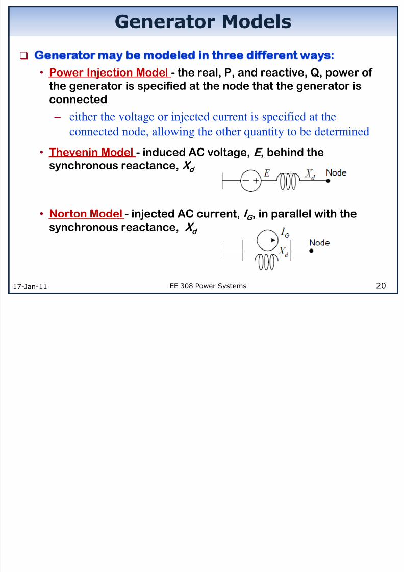
Generator Models
17-Jan-11 EE 308 Power Systems 20
Generator may be modeled in three different ways:
• Power Injection Model - the real, P, and reactive, Q, power of the generator is specified at the node that the generator is
connected
– either the voltage or injected current is specified at the
connected node, allowing the other quantity to be determined
• Thevenin Model - induced AC voltage, E , behind the
synchronous reactance, X d
• Norton Model - injected AC current, I G , in parallel with thesynchronous reactance, X
d

8/7/2019 lec _ PU systems-1
http://slidepdf.com/reader/full/lec-pu-systems-1 4/15
Transformer Model
Transformer equivalent circuit, with secondary impedancesreferred to the primary side
17-Jan-11 EE 308 Power Systems 21
Figure source: wikipedia

8/7/2019 lec _ PU systems-1
http://slidepdf.com/reader/full/lec-pu-systems-1 5/15
Load Models
Models are selected based on both the type of analysis and
the load characteristics. Three main static load models are: Constant impedance, Z
load
– Load is made up of R, L, and C elements connected to a network node
and the ground (or neutral point of the system)
Constant current, I load – The load has a constant current magnitude I , and a constant power factor,
independent of the nodal voltage
– Also considered as a current injection into the network
Constant power (PQ) , Sload
– The load has a constant real, P, and reactive, Q, power component
independent of nodal voltage or current injection
– Also considered as a negative power injection into the network
17-Jan-11 EE 308 Power Systems 22

8/7/2019 lec _ PU systems-1
http://slidepdf.com/reader/full/lec-pu-systems-1 6/15
Per Unit (PU) Analysis (1/4)
17-Jan-11 EE 308 Power Systems 23
P.U. : ratio of the actual quantity to its base values
1-Ø system
Base
Base
Base
Base
S MVA
V kV
3-Ø system
AV
SI
Base
Base
Base
1000
Base
Base
Base
Base
Base
S
V
I
V
Z
2
1000
2
Base
PU Actual
Base
SZ Z
V
Base
Base
Base
Base
Base
S
V
I
V
Z
2
3
1000
AV
SI
Base
Base
Base
3
1000

8/7/2019 lec _ PU systems-1
http://slidepdf.com/reader/full/lec-pu-systems-1 7/15
Per Unit (PU) Analysis (2/4)
17-Jan-11 EE 308 Power Systems 24
Changing the base of PU quantities
2
2
Old Old ActualNew PU Base
PU New New
Base Base
New Old
Base BaseOld
PU Old NewBase Base
Z Z Z Z
Z Z
S V Z
S V

8/7/2019 lec _ PU systems-1
http://slidepdf.com/reader/full/lec-pu-systems-1 8/15
Per Unit (PU) Analysis (3/4)
17-Jan-11 EE 308 Power Systems 25
1. Pick for the whole system
2. Pick arbitrarily (according to line-to-line voltage).
Relate all the others by transformer ratio.
3. Calculate for different zones.
4. Express all quantities in P.U.
5. Draw impedance diagram and solve for P.U. quantities.
6. Convert back to actual quantities if needed.
BaseS
BaseV
BaseZ
Steps for a PU analysis

8/7/2019 lec _ PU systems-1
http://slidepdf.com/reader/full/lec-pu-systems-1 9/15
Per Unit (PU) Analysis (4/4)
Divide circuit into zones by transformers.
Specify two base values out of ; for example,
and
Specify voltage base in the ratio of zone voltage (L-L).
17-Jan-11 EE 308 Power Systems 26
BaseSBaseV
BBBB SZ V I ,,,
Source
Zone 1 Zone 2 Zone 3 Zone 4
1BaseV 2BaseV
3BaseV 4BaseV
21 :V V 32 :V V 43 :V V
1
1
Base
Base
Base
SI
V 1
1
1
Base
Base
Base
V Z
I
How to Choose Base Values ?

8/7/2019 lec _ PU systems-1
http://slidepdf.com/reader/full/lec-pu-systems-1 10/15
Example 5.14, p. 164-166
17-Jan-11 EE 308 Power Systems 27
Given a one line diagram of
the 3-φ system,
gI loadV loadPloadI Tr I Find , , , , and .
“Power system analysis” by
A.R. Bergen and V. Vittal
~ 5 MVA
13.2 Δ – 132 Y kV
10 MVA
138 Y - 69 Δ kV
line 10 100Z j g
I
1 0.1 p.u.T X
2 0.08 p.u.T X
( ) 13.2g L LV kV
load 300Z
Tr I
Load I

8/7/2019 lec _ PU systems-1
http://slidepdf.com/reader/full/lec-pu-systems-1 11/15
Example 5.14 (Cont’d)
17-Jan-11 EE 308 Power Systems 28
Zone 1 Zone 2 Zone 3
3 10BS MVA
1B 13.8L LV kV
B2
138L LV kV
3B 69V kV
1
1
22L L
B
B
B
13.819.04
10
V kV Z
S MVA
2
2
22
B
B
B
1381904
10
L LV kV Z
S MVA
3
3
22
B
B
B
69476
10
L LV kV Z
S MVA
Step 1, 2, and 3: Base Values
~5 MVA
13.2 Δ – 132 Y kV
10 MVA
138 Y - 69 Δ kV
line 10 100Z j gI
1 0.1 p.u.T X 2 0.08 p.u.
T X
( ) 13.2g L LV kV
load 300Z
Tr I
Load I

8/7/2019 lec _ PU systems-1
http://slidepdf.com/reader/full/lec-pu-systems-1 12/15
Example 5.14 (Cont’d)
17-Jan-11 EE 308 Power Systems 29
Step 4: All per unit quantities
+
-
2
1,p.u. 2
13.2100.1 0.183
5 13.8T
kV MVAX
MVA kV
2 0.08p.u.T X
2
3lineline,p.u.
B
10 1005.25 10 1 10
1904
Z jZ j
Z
1
gg,p.u.
B
13.2 0.9565 013.8
V kV V V kV
3
loadload,p.u.
B
300 0.63476
Z Z Z
2
2
new old
base basenew old pu pu old new
base base
S V Z Z S V

8/7/2019 lec _ PU systems-1
http://slidepdf.com/reader/full/lec-pu-systems-1 13/15
Example 5.14 (Cont’d)
17-Jan-11 EE 308 Power Systems 30
Step 5: One phase diagram & solve
+
-
1,p.u.0.183T X
2 0.08T X 1011025.5 3
p.u.line, jZ
g,p.u. 0.9565 0V
63.0p.u.load, Z
g,p.u.
load,p.u.
total,p.u.
0.9565 01.35 26.4
0.709 26.4
V I
Z
g,p.u. Tr,p.u. load,p.u. 1.35 26.4I I I
load,p.u. load,p.u. load,p.u. 0.8505 26.4V I Z
*
load,p.u. load,p.u. load,p.u. 1.1474S V I

8/7/2019 lec _ PU systems-1
http://slidepdf.com/reader/full/lec-pu-systems-1 14/15
Example 5.14 (Cont’d)
17-Jan-11 EE 308 Power Systems 31
Zone 1 Zone 2 Zone 3
~line 10 100Z j
gI
kV V g 2.13
load 300Z
1g g,p.u. BI I I
2,p.u. BTr Tr I I I
3load load,p.u. BI I I
3load load,p.u. BV V V
load load,p.u. BS S S
g,p.u. Tr,p.u. load,p.u. 1.35 26.4I I I
load,p.u. 0.8505 26.4V
load,p.u. 1.1474S
Step 6: Convert back to actual quantities
5 MVA
13.2 Δ – 132 Y kV
1 0.1 p.u.T X
10 MVA
138 Y - 69 Δ kV
2 0.08 p.u.T X
1
1
3
B L L
B
BS
I V
2B
13.2 418.4 41.84132
I
6
3
10 10 3418.4
3 13.8 10
3B
138
41.84 83.6769I

8/7/2019 lec _ PU systems-1
http://slidepdf.com/reader/full/lec-pu-systems-1 15/15
Advantages of P.U. System
P.U. representation results in a more meaningful data. It
gives a clear idea of relative magnitudes of various
quantities.
It is more uniform compare to actual impedance value of
different sizes of equipment
It is very useful in simulating power systems for steady-
state and dynamic analysis.
The P.U. equivalent impedance, voltages, and currents of
any transformers are the same referred to either primary
or the secondary side.
– Different voltage levels disappear across the entire system.
– The system reduces to a system of simple impedances
– P.U. impedance is the same irrespective of the type of 3-φ
transformer
17-Jan-11 EE 308 Power Systems 32


![Lec-1 Introduction to Database Systems[1]](https://img.pdfslide.us/doc/110x75/577ce0dd1a28ab9e78b4470a/lec-1-introduction-to-database-systems1.jpg)