Embed Size (px)
Citation preview
1
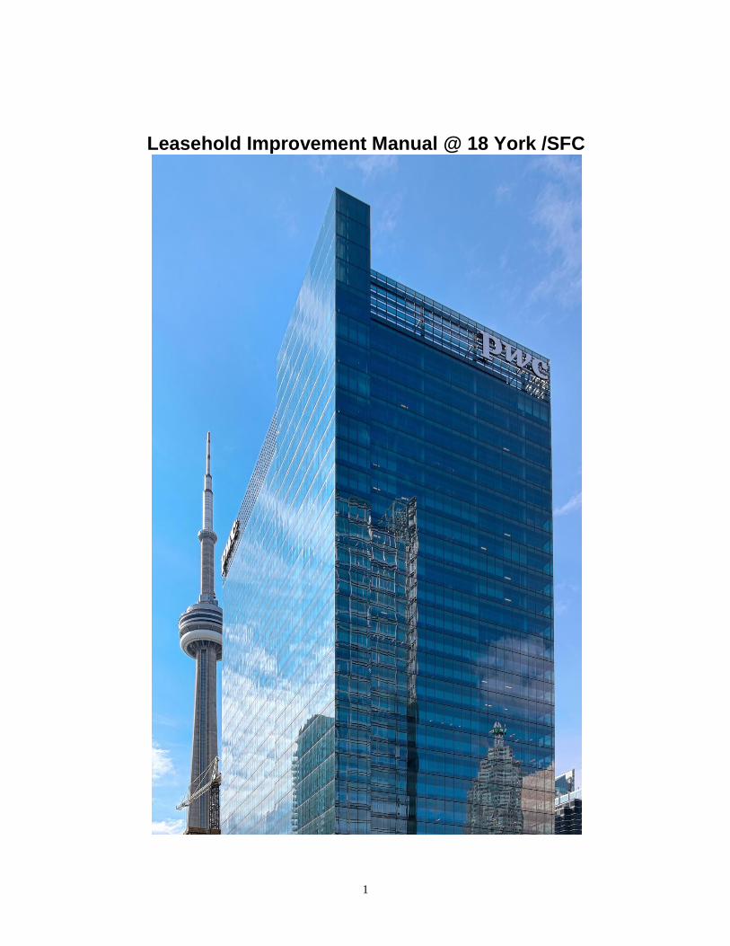
Leasehold Improvement Manual @ 18 York /SFC

2
Southcore Financial Centre Revised September 17, 2012 CONTACTS
PROPERTY MANAGEMENT CONTACTS General Contact number during Business Hours: Tel: 416-861-0322 EMERGENCY PHONE NUMBER Tel: 416-861-9188 Chris Tiessen Tel: 416-861-0322 Ext. 101 Property Manager Mike Paul Tel: 416-861-0322 Ext. 102 Senior Manager, Technical Services Mark Chartrand Tel: 416-861-0322 Ext. 106 Building Operator Emma Messum Tel: 416-861-0322 Ext. 100 Tenant Services Coordinator
Development Contact Jennifer Shaw Tel: 416 552 3908 Landlords Representative for Tenant Fit-up, including Design Approval
3
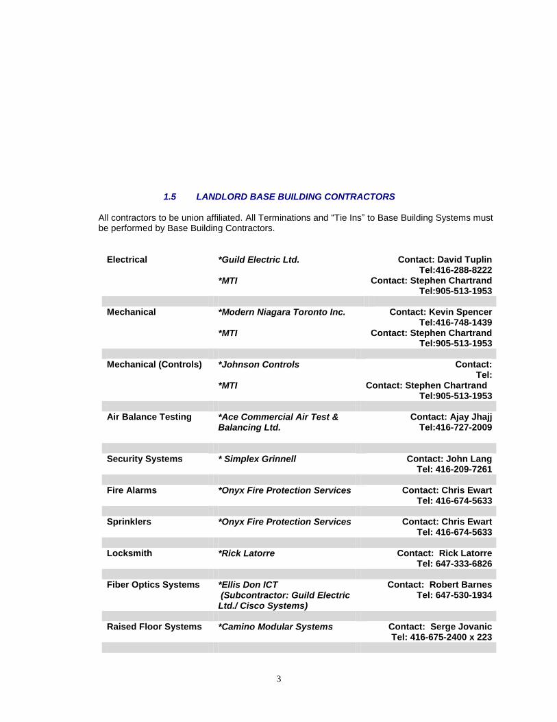
1.5 LANDLORD BASE BUILDING CONTRACTORS
All contractors to be union affiliated. All Terminations and “Tie Ins” to Base Building Systems must be performed by Base Building Contractors.
Electrical *Guild Electric Ltd. *MTI
Contact: David Tuplin Tel:416-288-8222
Contact: Stephen Chartrand Tel:905-513-1953 Mechanical *Modern Niagara Toronto Inc.
*MTI
Contact: Kevin Spencer Tel:416-748-1439
Contact: Stephen Chartrand Tel:905-513-1953
Mechanical (Controls) *Johnson Controls
*MTI
Contact: Tel:
Contact: Stephen Chartrand Tel:905-513-1953
Air Balance Testing *Ace Commercial Air Test &
Balancing Ltd.
Contact: Ajay Jhajj Tel:416-727-2009
Security Systems * Simplex Grinnell Contact: John Lang
Tel: 416-209-7261 Fire Alarms *Onyx Fire Protection Services Contact: Chris Ewart
Tel: 416-674-5633 Sprinklers *Onyx Fire Protection Services Contact: Chris Ewart
Tel: 416-674-5633 Locksmith
*Rick Latorre Contact: Rick Latorre Tel: 647-333-6826
Fiber Optics Systems *Ellis Don ICT
(Subcontractor: Guild Electric Ltd./ Cisco Systems)
Contact: Robert Barnes Tel: 647-530-1934
Raised Floor Systems *Camino Modular Systems Contact: Serge Jovanic
Tel: 416-675-2400 x 223

4
Blinds *SolarFective Products Limited Contact: Bruce Broer Tel: 416-421-3800
LANDLORD APPROVED CONTRACTORS
Base Building Contractors All contractors to be union affiliated. Trade Company Electrical Guild Electric Ltd. Mechanical MTI Mechanical (Controls) MTI Security Systems Guild Electric Ltd.
(Supplier- Simplex Grinnell)
Fire Alarms Onyx Fire Protection
Sprinklers Onyx Fire Protection Locksmith GWL Realty Advisors
Fiber Optics Systems EllisDon ICT
Raised Floor Systems Camino Modular Systems
Blinds Solarfective Products Ltd. Air Balancing & Chilled Water Ace Commercial Air Test & Balancing Ltd. Drywall & Acoustics Ardnek

5
Trade Company Mechanical Adelt Mechanical Modern Niagara Mechanical MTI Sprinklers Onyx Fire Protection Electrical MTI Guild Electric Communications Guild Electric Acoustic Wall Panels GWP Architectural Products. Wood Doors, Frames & Millwork
Ardnek Finishing Hardware / Washroom Accessories
Trillium Architectural Products Empire Hardware Upper Canada Hardware City Wide Hardware Rough Carpentry Ardnek
6
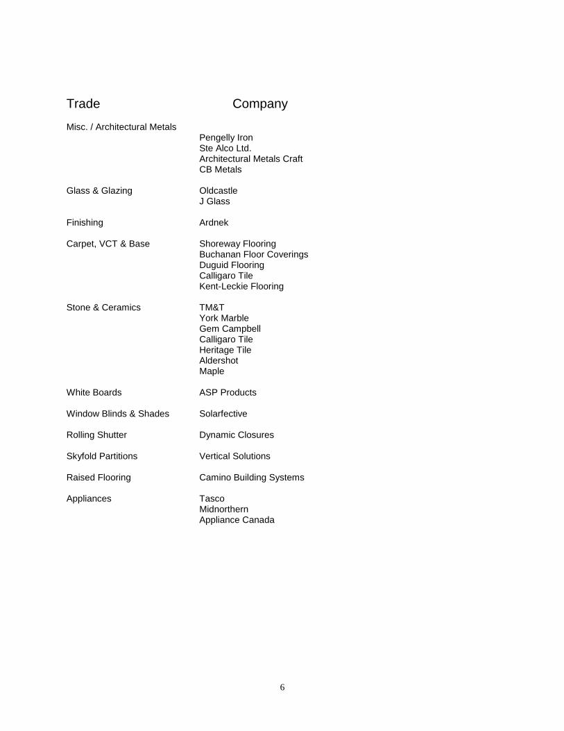
Trade Company
Misc. / Architectural Metals
Pengelly Iron Ste Alco Ltd. Architectural Metals Craft CB Metals Glass & Glazing Oldcastle J Glass Finishing Ardnek Carpet, VCT & Base Shoreway Flooring Buchanan Floor Coverings Duguid Flooring Calligaro Tile Kent-Leckie Flooring Stone & Ceramics TM&T York Marble Gem Campbell Calligaro Tile Heritage Tile Aldershot Maple White Boards ASP Products Window Blinds & Shades Solarfective Rolling Shutter Dynamic Closures Skyfold Partitions Vertical Solutions Raised Flooring Camino Building Systems Appliances Tasco Midnorthern Appliance Canada

7
Trade Company
Office Fronts Unifor / Italinteriors Dirtt / Dreschel Hollow Metal Trillium Architectural Products CDS Security Simplex Grinnell Audio Visual First Vision Nationwide Westbury Design Electronics Applied Electronics General Contractors Confra
Shurway Vestacon Charterhouse Cesaroni Vandyk Rosscor
Claybar Venture Construction EllisDon Fairgate Ltd
8
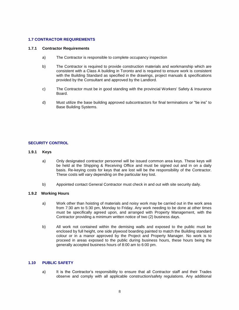
1.7 CONTRACTOR REQUIREMENTS 1.7.1 Contractor Requirements
a) The Contractor is responsible to complete occupancy inspection
b) The Contractor is required to provide construction materials and workmanship which are
consistent with a Class A building in Toronto and is required to ensure work is consistent with the Building Standard as specified in the drawings, project manuals & specifications provided by the Consultant and approved by the Landlord.
c) The Contractor must be in good standing with the provincial Workers' Safety & Insurance
Board. d) Must utilize the base building approved subcontractors for final terminations or “tie ins” to
Base Building Systems. SECURITY CONTROL 1.9.1 Keys
a) Only designated contractor personnel will be issued common area keys. These keys will
be held at the Shipping & Receiving Office and must be signed out and in on a daily basis. Re-keying costs for keys that are lost will be the responsibility of the Contractor. These costs will vary depending on the particular key lost.
b) Appointed contact General Contractor must check in and out with site security daily.
1.9.2 Working Hours
a) Work other than hoisting of materials and noisy work may be carried out in the work area
from 7:30 am to 5:30 pm, Monday to Friday. Any work needing to be done at other times must be specifically agreed upon, and arranged with Property Management, with the Contractor providing a minimum written notice of two (2) business days.
b) All work not contained within the demising walls and exposed to the public must be
enclosed by full height, one side plywood boarding painted to match the Building standard colour or in a manor approved by the Project and Property Manager. No work is to proceed in areas exposed to the public during business hours, these hours being the generally accepted business hours of 8:00 am to 6:00 pm.
1.10 PUBLIC SAFETY
a) It is the Contractor‟s responsibility to ensure that all Contractor staff and their Trades
observe and comply with all applicable construction/safety regulations. Any additional
9
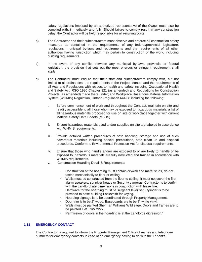
safety regulations imposed by an authorized representative of the Owner must also be complied with, immediately and fully. Should failure to comply result in any construction delay, the Contractor will be held responsible for all resulting costs.
b) The Contractor and their subcontractors must observe and enforce all construction safety
measures as contained in the requirements of any federal/provincial legislature, regulations, municipal by-laws and requirements and the requirements of all other authorities having jurisdiction which may pertain to construction of the work, including building requirements.
c) In the event of any conflict between any municipal by-laws, provincial or federal
legislation, the provision that sets out the most onerous or stringent requirement shall apply.
d) The Contractor must ensure that their staff and subcontractors comply with, but not
limited to all ordinances, the requirements in the Project Manual and the requirements of all Acts and Regulations with respect to health and safety including Occupational Health and Safety Act, RSO 1980 Chapter 321 (as amended) and Regulations for Construction Projects (as amended) made there under; and Workplace Hazardous Material Information System (WHMIS) Regulation, Ontario Regulation 644/88 including the following:
i. Before commencement of work and throughout the Contract, maintain on site and
readily accessible to all those who may be exposed to hazardous materials, a list of all hazardous materials proposed for use on site or workplace together with current Material Safety Data Sheets (MSDS).
ii. Ensure hazardous materials used and/or supplies on site are labeled in accordance
with WHMIS requirements.
iii. Provide detailed written procedures of safe handling, storage and use of such hazardous materials including special precautions, safe clean up and disposal procedures. Conform to Environmental Protection Act for disposal requirements.
iv. Ensure that those who handle and/or are exposed to or are likely to handle or be
exposed to, hazardous materials are fully instructed and trained in accordance with WHMIS requirements.
v. Construction Hoarding Detail & Requirements:
• Construction of the hoarding must contain drywall and metal studs, do-not
fasten mechanically to floor or ceiling. • Walls must be constructed from the floor to ceiling; it must not cover the fire
alarm speakers, sprinkler heads or Security cameras. Contractor is to verify with the Landlord site dimensions in conjunction with lease line.
• Hardware for the hoarding must be sergeant lever set. Cylinder is to be provided to base building Locksmith for keying.
• Hoarding signage is to be coordinated through Property Management. • Door trim is to be 2” wood. Baseboards are to be 3” white vinyl. • Walls must be painted Sherman Williams Wild sage. Doors and frames are to
be painted TWT SW 2227.
• Permission of doors in the hoarding is at the Landlords digression.” 1.11 EMERGENCY CONTACT
The Contractor is required to inform the Property Management Office of names and telephone numbers for emergency contacts in case of an emergency having to do with the Tenant's
10
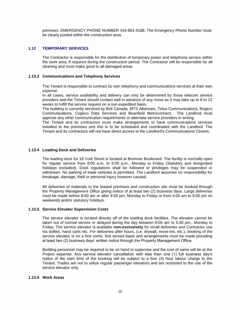
premises. EMERGENCY PHONE NUMBER 416-861-9188. The Emergency Phone Number must be clearly posted within the construction area.
1.12 TEMPORARY SERVICES
The Contractor is responsible for the distribution of temporary power and telephone service within the work area, if required during the construction period. The Contractor will be responsible for all cleaning and must make good to all damaged areas.
1.13.2 Communications and Telephony Services
The Tenant is responsible to contract its own telephony and communications services at their own expense. In all cases, service availability and delivery can only be determined by those telecom service providers and the Tenant should contact well in advance of any move as it may take up to 8 to 12 weeks to fulfill the service request on a non-expedited basis.
The building is currently serviced by Bell Canada, MTS Allstream, Telus Communications, Rogers Communications, Cogeco Data Services and Beanfield Metroconnect. The Landlord must approve any other communication requirements or alternate service providers in writing. The Tenant and its contractors must make arrangements to have communications services installed to the premises and this is to be scheduled and coordinated with the Landlord. The Tenant and its contractors will not have direct access to the Landlord's Communications Closets.
1.13.4 Loading Dock and Deliveries
The loading dock for 18 York Street is located at Bremner Boulevard. The facility is normally open for regular service from 8:00 a.m. to 5:00 p.m., Monday to Friday (Statutory and designated holidays excluded). Dock regulations shall be followed or privileges may be suspended or withdrawn. No parking of trade vehicles is permitted. The Landlord assumes no responsibility for breakage, damage, theft or personal injury however caused.
All deliveries of materials to the leased premises and construction site must be booked through the Property Management Office giving notice of at least two (2) business days. Large deliveries must be made before 8:00 am or after 6:00 pm, Monday to Friday or from 6:00 am to 6:00 pm on weekends and/or statutory holidays.
1.13.5 Service Elevator Supervision Costs
The service elevator is located directly off of the loading dock facilities. The elevator cannot be taken out of normal service or delayed during the day between 8:00 am to 5:30 pm., Monday to Friday. The service elevator is available non-exclusively for small deliveries and Contractor use via dollies, hand carts etc. For deliveries after hours, (i.e. drywall, move-ins, etc.), booking of the service elevator is on a first come, first served basis and arrangements must be made providing at least two (2) business days‟ written notice through the Property Management Office. Building personnel may be required to be on hand to supervise and the cost of same will be at the Project expense. Any service elevator cancellation with less than one (1) full business day‟s notice of the start time of the booking will be subject to a four (4) hour labour charge to the Tenant. Trades are not to utilize regular passenger elevators and are restricted to the use of the service elevator only.
1.13.6 Work Areas
11
All construction materials, tools, equipment and workbenches must be kept within the work area throughout the construction period. The security of tools/materials is the responsibility of the Contractor. All public lobbies, corridors, washrooms and stairs shall be kept clear of construction materials at all times. Floor mats must be laid down at all exits and must be vacuumed regularly to minimize dust.
1.13.7 Garbage
a) Corridors, exits, freight elevator lobbies and common areas must be kept clear at all
times. Removal of all construction garbage is the responsibility of the Contractor. Arrangements must be made for service elevator time to remove construction debris to the loading dock. Because of limited space, the Contractor must immediately remove debris from the site by means of a non-marking rubber wheeled cart by the contractor. The Contractor is required to allocate all waste into the appropriate designated waste stream compactors.
b) Removal of Construction debris is the responsibility of the Contractor and will be scheduled between the hours of 6:00 pm to 6:00 am. Bins will only be accepted on site during these hours. Booking of the service elevator for down loading must be coordinated through the Property Management Office with a minimum notice of two (2) business days. The Contractor is responsible for the most efficient use of the service elevator at the Landlord's discretion. A building security representative may be required, at the discretion of Property Management, after hours and the cost of same will be charged to the Tenant.
Note: Garbage of a flammable nature (i.e. paper) must not be allowed to accumulate, but must be removed from the site as quickly as possible.
1.14 PARKING
Property Management does not provide parking for contractor personnel and there is no special area reserved for this purpose. Vehicles parked illegally on the property are subject to tagging and/or towing at the vehicle owner‟s expense. There is a paid parking facility within the complex; however. Vehicles exceeding the max height are not permitted access.
1.15 TEMPORARY FIRE PROTECTION DEVICES
Operable fire extinguishers must be kept within the work area throughout the construction period and these extinguishers must be sufficient in number and of suitable type to combat a potential fire in the work area. Any Contractors or Subcontractors working with an open flame must provide their own fire extinguishers for use. Base building extinguishers are not to be removed from cabinets. Approval from Property Management must be obtained before any work of this nature is undertaken.
1.16 SECURITY OF LEASED PREMISES
The Contractor is fully responsible for the physical security of the premises and the contents
12
thereof throughout the construction period. The Contractors shall be restricted to the enclosed work area for all work and storage of all construction materials, tools and equipment.
Contractors shall in no way prop open and/or alter any Building security device/door without the prior written approval by Property Management. Should a door schedule modification be required, the on-duty Security Officer should be contacted.
1.17 FASTENINGS
Contractors are not permitted to mechanically fasten to window frames, fire-rated walls or exterior walls containing structural air/vapour barriers.
1.19 STORAGE AND DISPOSAL OF HAZARDOUS WASTE MATERIAL
Construction generated hazardous waste shall be removed from the property on a daily basis.
1.20 PROTECTION OF BASE BUILDING ELEMENTS 1.20.1 Windowsill enclosures
Windowsill enclosures shall not be used as a step or for storage of materials, etc. Repairs for damages shall be the responsibility of the Contractor. The perimeter heating grill shall be covered with filter media during the construction period to prevent dust and debris infiltration.
1.20.2 Mechanical and Electrical Rooms
The Contractor shall be responsible for cleaning and making good any damages to the Mechanical and Electrical rooms. In particular, floor drains shall not be used for the dumping of liquid garbage, etc.
1.20.4 Stairs and Access Areas
The Contractor is responsible for cleaning and making good damages to stairs and areas used for access during the Work. Note: stairs, lobbies and corridors damaged must be made good. Contractors shall not wedge fire doors in stairs open.
1.21 TIE-INS
The Contractor must obtain Property Management‟s permission to co-ordinate installation and any tie-ins to mechanical, electrical, fire protection or life/safety systems or controls. All terminations and tie-ins to Base Building Systems must be performed by the Base Building Contractor, at the Contractor‟s cost.
1.23 FIRE ALARM
13
1.23.1 Sprinkler System
All changes to the base building sprinkler system must be co-ordinated with Property Management. The sprinkler control valve will be closed and the sprinkler line drained down each day until all revisions on each floor are completed. All sprinkler system components must be able to be made operable at the end of each day. Property Management must be contacted at least two (2) business days in advance of any proposed sprinkler work, and before commencing work on the site. All precautions must be taken to ensure false fire alarms do not take place. Charges will be levied against the Contractor‟s account ($500.00 per alarm, etc.). Sprinkler work requiring isolation of occupied areas must be completed during normal business hours (9:00 am to 5:00 pm, Monday to Friday). The Contractor must provide a fire watch person for occupied areas in accordance with the building fire plan. Work outside of these hours must be scheduled with the Property Management Office.
After completion of all Contractor work the system must be water pressure tested at 150 psi for two (2) hours. The base building engineering consultant must witness the test and send the test certificate to the Property Management Office. The sprinkler system will be reactivated once all tests have been approved.
A temporary smoke detection system must be installed in the event that the sprinkler system and building smoke detection system become inoperable at the end of each day.
1.23.2 Fire Alarm and Devices
All final terminations and tie-ins to the base building fire alarm system shall be performed by the base building fire alarm contractor. The contractor is responsible for the scheduling of this work and cost. Arrangements must be made with the Property Management Office prior to performing any work on the fire alarm system. Only building personnel are allowed to isolate the fire alarm panel when modifying, installing and/or relocating any alarm devices (i.e. pull stations, communication speakers, fire alarm bells, etc.). The Contractor will be charged $500.00 per alarm should there be an inadvertently caused alarm. The fire alarm system must be in an operable condition at the end of each day before 5:00 pm.
1.24 DRILLING OR CUTTING WORK AND X- RAYS
The Contractors may not drill or cut openings of any type in any part of the base building structure, except where such work is deemed to be necessary and is approved in writing by the Project Manager and the building structural engineer, in advance. It is the responsibility of the Contractor to request this approval. Scheduling of this work must be given by the Contractor to the Property Management Office in writing, five (5) business days in advance, complete with drawings detailing x-ray locations and all other affected areas prior to floor access. All x-ray shots must be done between the hours of 12:00 am and 5:00 am. The contractor must ensure the floors and/or areas affected are marked on the provided work permit. The contractor must also place signage at all access points to the affected area, including stairwells and elevator lobbies. The Property Management Office must be provided a minimum of three (5) business days‟ notice should access into another Tenant space be required.
All abandoned openings are to be make good by the Contractor, generally this will mean filled with concrete and guaranteed to be secure.
14
1.25 WELDING, OPEN FLAME AND HOT WORK PERMITS
Open flames for welding, cutting or other purposes are not permitted without the prior consent of the Property Management Office AND the Contractor must obtain a Hot Work Permit, which are available from the security desk. Proposed work of this nature must be approved by Property Management in writing with at least two (2) business days‟ notice before the work is to be done. An operational fire extinguisher must be available in the immediate vicinity of the work, in addition to those already present. The Contractor shall coordinate shut off or covering of the smoke detectors with Property Management. Should the Contractor neglect to obtain the proper authorizations, or take the required precautions and a fire alarm is activated, resulting in a false alarm, the Contractor may be charged with all associated costs plus a fine of $500.00 per occurrence.
1.25.1 Procedure for Cutting and Welding Operations
All cutting and welding must be conducted in a safe manner, to prevent fires and to ensure that building occupants are not inconvenienced. This procedure outlines how cutting and welding operations are to take place: a) Any Contractor conducting welding, cutting, soldering or any other hot work must obtain a
Hot Work Permit before commencing any work. With the exception of onsite maintenance staff, Hot Work Permits are only issued to Contractors with a valid work permit.
b) The Contractor will go to the Security Desk to obtain their Hot Work Permit. The
Contractor will show Security their work permit number, and inform them of the location of their work, and the expected duration of their work. Security must also be instructed by the Contractor to ensure that the smoke detectors in the area of work have been bypassed before any work commences.
c) Once the Hot Work Permit has been issued, but before work has commenced, an
inspection of the job site must be carried out by Security personnel, to ensure the area is safe and necessary regulations are being followed. The following must be done:
i. All combustible items must be removed from the work area, at a distance of 7.5
meters (25 feet). This includes sweeping the floors of dust and debris. Anything that cannot be removed must be covered with a fire-resistant tarp.
ii. Any flammable liquids (oil, paint, solvents) must be removed from the work area. iii. Any openings in walls, floors or ductwork must be covered with a fire-resistant
cover. iv. The Contractor must have a fully charged, working fire extinguisher at the hot
work site. The Contractor must provide a 5lb ABC extinguisher at each welding site but must not use the building‟s fire extinguishers. If welding is taking place in more than one location at the job site, an extinguisher must be provided for each location.
v. The Hot Work Permit must be prominently displayed at the welding site. vi. If hot work is being conducted in an open area, where other persons will be
passing by, protective fire-resistant curtains must be put up to prevent people seeing the arc, or being hit by sparks.
15
d) Welders will operate their equipment in a safe, responsible manner. Cutting and welding apparatus shall be used in accordance with NFPA 51B (Standards for Fire Protection in use of Cutting and Welding Process) and the Manufacturer‟s guidelines.
e) While the work is being conducted, the workers must take all possible precautions to
ensure that sparks and slag do not spread out from the work area. Frequent checks should be made to ensure that all is well in the area.
f) The workers shall ensure that excessive amounts of fumes and smoke are not generated
by the work. If fumes and smoke begin to accumulate, the work should be temporarily stopped until the air clears. It may be necessary for the contractor to provide portable ventilation equipment to manage the fumes on the job site.
g) Under no circumstances is galvanized metal duct to be cut with an oxy-acetylene torch.
All cutting of such material will be by way of saw or plasma cutter. h) When the work is completed, the welder should remain for another thirty (30) minutes
carefully inspecting the work area and adjacent areas for any smouldering fires. If applicable, this inspection should extend to floors above and below the work area and adjacent rooms. Barring any fires, the welder will then sign the permit and return the permit to the Security Desk located in the main lobby.
i) Any safety guidelines on the permit must be adhered to. It is the responsibility of the
Contractor to return their portion of the permit immediately once the job is completed. The Contractor portion of the permit must also be signed by the welder to confirm that the affected area has been inspected thirty (30) minutes after the job was completed. Security and Safety personnel will then complete an inspection of the authorized cutting and welding area two to four hours after the job has been completed by the contractor, his portion of the permit must be returned to the Shipping Guard. Failure to return the signed portion of the permit immediately after the thirty minute check will result in the penalties mentioned above.
1.26 WATER SYSTEM SHUTDOWNS
All requests for water system shutdowns (fire, line, domestic, chilled or condenser water, etc.) must be submitted in writing for approval to the Property Management Office at least two (2) business days before the shutdown date.
1.27 CARPET INSTALLATION
Carpet adhesives must be LEED Compliant. Installation of all carpet on an occupied floor must be completed after normal business hours.
1.28 PLUMBING AND METERING
Where plumbing is removed from Work area, all water supply, drain lines and vent connections must be removed from the ceiling spaces back to the core riser and properly capped. All meter reading units are to be located in base building riser rooms. Measurement Canada approved Meter Manager
TM electronic submeters are to be used. The Contractor is responsible for all tie-
ins, using Base Building Contractors, to the Base Buildin System and is responsible for any additional programming or connection required for the meter to be integrated into the Base Building System.
16
1.29 DAILY CLEAN-UP
Contractors must ensure that corridors are left free of debris and must remove dirt and marks from corridor walls, floors, doors, etc., on a daily basis. Where special cleaning is required to maintain the corridor's neat appearance, such cleaning will be done at the Contractor's expense.
1.30 COMPLETION OF WORK
1.30.1 Obligations
a) At the completion of work, the Contractor must provide the Project Manager and Property Management with two sets of complete "as-built" drawings, on a CD in electronic AUTOCAD format and all close-out documents. An Electrical Safety Authority Certificate of Approval must also be submitted.
b) All elements of the base building, such as, but not limited to, light fixtures, ceiling tiles,
doors and frames, hardware etc., that the Tenant removes with the approval of the Landlord remain the property of the Landlord and must be delivered back to the Property Management Office in good working condition.
c) At the completion of construction the work area must be left clean and in a “broom swept” condition which is acceptable by the Project Manager and Property Manager. The Property Manager‟s cleaning contractor may be retained at the Contractor's expense to complete this work.
d) In addition to the foregoing obligations, Contractor is also responsible for ensuring, before premises are occupied or re-occupied, that the following areas and/or items are cleaned:
i. Light fixtures and lenses. ii. Ceiling and ceiling tiles. iii. Floor tiles and carpets. iv. Corridor walls and doors immediately adjacent to the leased premises. v. Interior side of perimeter window frames (sills, jambs, headers). vi. Interior side of all perimeter exterior windows and any partition glass installed
within the leased premises. vii. All service rooms. viii. “Solarfective” blinds. ix. The filters for the floor air-handling unit if used during construction, may be
replaced at the Contractor‟s expense. 1.32 AIR BALANCING REPORT

17
The Contractor must engage the Property Manager‟s Air Balancing Contractor to provide an air balancing report upon completion of the work. A complete floor fan system air balance may be required as part of the retrofit scope of work for any partial or full floor occupancy.
1.34 CONSTRUCTION NOISE
Work such as coring, chipping and drilling must be carried out during non-business hours with the prior approval of the Property Management Office. The Property Management Office reserves the right to request any work involving noise levels that are sufficient to result in the disruption of surrounding Tenants‟ quiet enjoyment of their leased premises be immediately stopped and rescheduled to after hours. Under no circumstances will the Property Manager, Project Manager or the Owner be held accountable for any cost increases incurred by the Contractor for alternate scheduling of the associated work.
1.35 SITE MEETINGS
The Contractor is to arrange and record, on a weekly interval during construction, site meetings to include representatives of the Contractor, Sub-trades, the Project Manager and Property Management, in order to co-ordinate the work, deal with any problems, alter or arrange schedules and update work progress, etc.
2.3.5 Telecommunications Infrastructure
a) A complete communications raceway system is installed in the communications closets. The raceway system is terminated in the main telecommunication room, located on Level P1, permitting connection to off-site networks through a service provider of choice. Access to the vertical raceway system is only under specific approval of the Landlord and only upon receipt and review of the plans and specifications provided by the Tenant to the Landlord. Where possible, the Tenant shall use the base-building fibre and copper infrastructure supplied by or installed by the Landlord.
a. The Tenant must provide a statement of work or other written documentation, acceptable
to the Landlord, which indicates use of building infrastructure , raceways, sleeves or conduit by their telecommunication provider. The Landlord reserves the right to approve the use of or assign the sleeve location of any additional cabling for use by the Tenant or installed on their behalf by their telecommunications provider. All costs are the responsibility of the Tenant. The building entrance ducts permits both fibre optic and copper based telecommunication carrier services to enter the building from multiple service providers from two sides of the building (diverse entry). The Main Telecommunications Room and Carrier Point of Presence Rooms will be connected to a building communications pathway riser system servicing all floors of the building for vertical transport of the building backbone cabling requirements by the Tenant and its service provider. The Tenant is responsible for installing all necessary communication cabling and equipment from the incoming service entrance to its floor.
b) The Tenant shall provide plans and specifications and working drawings to the Landlord for the Landlord‟s review and approval. The Tenant or Tenant‟s contractor will provide as-built plans upon completion and acceptance of the project by the Landlord.
18
c) Ground Floor and Level 2 retail areas are to be reviewed on a case by case basis. d) All wiring in the raised access flooring system (i.e. telephone and data communication
lines) must be completely enclosed in conduit or in the raised access flooring system and is subject to Appendix 1.
e) Redundant, obsolete or abandoned cabling must be removed back to source (as required by the National Electrical Code). Tenant shall provide to the Landlord evidence the Landlord reasonably requires confirming compliance by the Tenant with this obligation, and as required from time to time.
2.5 STANDARDS 2.5.1 Door Hardware
a) All door locks installed by the Contractor, on both entrance and interior doors, must be keyed to the building master and sub-master keying system using building standard door hardware.
b) The Property Management Office must be involved with all proposed keying changes or
additions. Outside locksmiths or lock manufacturers are not permitted to change the keying of any locks.
c) It is advisable that the Contractor contact the Property Management Office before
purchasing a hardware system to ensure that it is compatible with the base building system.
CONTRACTOR RESPONSIBILITIES 3.1 MECHANICAL 3.1.1 Labour, Materials & Fees
a) Provide all labour and new materials for the complete installation of the systems as per the Project Manual and List of Drawing. Ensure that complete installation meets with the approval of all authorities having jurisdiction in accordance with all codes, etc.
b) Use materials that are C.S.A., U.L.C., code approved and C.G.A. or Ontario Hydro
certified for the intended application.
c) All work must comply with the approved design drawings and specifications. The Landlord
reserves the right to have the Base Building Mechanical Consultant visit and review the work at appropriate milestones during the project to ensure the mechanical design is consistent with the approved design. It is the Tenant‟s responsibility to schedule these reviews and to correct any work found not in compliance with the approved design. This includes any changes made by the Tenant after approval of the Landlord of the submitted design. All costs are the responsibility of the Tenant.
3.1.2 Examination of the Site
a) Examine the site and be familiar with all the conditions covered by these specifications.
19
Extras will not be allowed for failure to properly evaluate conditions. b) Take field dimensions prior to any installation.
3.1.3 Compliance with Codes
a) Comply with all latest relevant codes and local regulations having jurisdiction including
O.B.C., N.B.C., N.F.P.A. 13, C.G.A. 149.1, C.S.A., O.W.R.A. 675/85, Canadian Plumbing Code, Ontario Hydro Code.
3.1.4 Debris & Clean Up
a) Keep premises clean as work progresses, avoid accumulation of debris, ensure that during construction all open vents are sealed and any controls (thermostats etc.) are covered. On completion of the work, clean up and remove from site all scrap materials resulting from the work. Clean all equipment prior to final inspection.
3.1.5 Warranty
a) Guarantee all work, equipment and materials for one (1) year from substantial completion of the contract (A/C unit compressors – five (5) years).
b) Ensure that all equipment is properly guaranteed by the manufacturer.
3.1.6 Shop Drawings
a) Submit shop drawings of all fixtures and equipment (including wiring diagrams) to the Consultant for approval. Approval of shop drawings does not relieve the Contractor of his responsibilities.
3.1.7 Cutting and Patching
a) Provide cutting and patching for work. Arrange to provide for the making good to finishes and include for the cost of this work.
3.1.9 Wiring
a) Ensure coordination between trades to avoid gaps and overlaps and to ensure all
equipment is operational, programmed and integrated into the Base Building Systems
3.1.10 Demonstration
a) Allow for demonstration of all equipment to Property Management and operating staff, if requested to do so.
3.1.12 Alternatives
a) Assume full responsibility that the equipment offered as an alternative is suitable for the space allocated, and for any additional costs to any part of the work resulting from the use of an alternate.
b) No deviation from plans and specifications will be allowed unless written approval is first

20
obtained from the Consultant.
3.1.13 Maintenance & Operating Instructions
a) Provide two (2) copies of manufacturers' maintenance and operating instructions for all equipment. Present the instruction in indexed three ring hard cover binders, with spine label project indicator, and index sheet. Including all shop drawings, permits, warranty details, certificates, contractor names, and telephone number lists for all project trades.
3.1.14 Interruption of Services
a) Any interruptions of the base building systems shall be co-ordinated with Property
Management for the time and duration and the Contractor shall strictly adhere to instructions in this regard.
3.1.15 Workmanship
a) Employ a responsible foreman to supervise the work and retain for duration of construction period.
b) Employ only skilled plumbers, steam fitters, sheet metal workers for the execution of the work. Workmanship shall be first class as regards to durability, efficiency, safety, and neatness of detail.
c) Identify all visible piping fully exposed or in accessible spaces (i.e. lay-in ceilings) with legend lettering, direction of flow and field colour band.
Legend & Flow Field
Medium Legend Arrow Colour Colour Band
Heat Pump Water Supply H.P.W.S. Black Light Green
Heat Pump Water Return H.P.W.R. Black Light Green
Condensate Cond. Black Black
Cold Water C.W. Black Light Blue
Domestic Hot Water D.H.W. Black Dark Blue
Sanitary Sewer San. White Black
Plumbing Vent Line Vent Black Black
Radiation Heat Supply HWS White Purple
Radiant Heat Return HWR White Purple
Condenser Water Supply CWS White Dark Green
Condenser Water Return CWR White Dark Green
3.2.6 Valve Tagging
21
a) All valves shall have securely affixed to them a brass plate tag with embossed black
numbers.
b) Prepare for Property Management a list of valve numbers indicating location and function.
3.2.7 Access Doors a) Provide approved access doors to all valves, and etc.
3.3 H.V.A.C. 3.3.5 Balancing
a) Engage the service of the Landlord‟s balancing contractor to balance and test all air
handling systems under this section.
b) This contractor shall:
i. Review drawings, specifications, and installed work to ensure that systems may be properly balanced in accordance with drawings. Advise installing contractor of any additional requirements for effective balancing.
ii. Ensure that air handling systems are free from obstructions, dampers are
positioned correctly, moving equipment is lubricated in accordance with manufacturer's recommendations, and that filters are clean.
iii. “It is the Tenant‟s responsibility to ensure that any blockages or
temporary barriers, due to construction activities to control dust, are removed before the base building balancer starts balancing and testing. Tenants and tier Contractors should note that temporary barriers left in place during construction are frequently discovered as the cause for low air volumes in Tenant spaces. Tenants are encouraged to make this a specific condition with their General Contractor as any additional work and rebalancing are the Tenant‟s Responsibility.”
iv. Demonstrate that the air handling system's performance is as specified. v. Tabulate and certify test results on suitable forms and submit to the Landlord for
approval record.
3.4 ELECTRICAL 3.4.1 General
a) All work shall be in accordance with the latest edition of the Ontario Hydro Code, Local
Inspection, Ontario Building Code, and any other ordinance. b) Examine the site and all drawings and specifications of all trades and be familiar with the
work of this trade. No allowances will be made for the failure to do so.
22
c) All electrical work shall comply with C.S.A. electrical bulletins applicable to tender close.
Where specific bulletins are not named they are still considered an integral part of this specification.
d) Grounding shall be in accordance with the requirements of the Ontario Electrical Code.
Provide all grounding required regardless if not shown on the drawings. e) Provide all new materials having C.S.A. approval. All workmanship shall be first class in
regard to standard practices, safety, accessibility, durability and neatness of detail for acceptance by the Landlord's representative.
f) Arrange and pay for all permits and inspection fees required for the work of this trade. It is
the responsibility of this contractor to submit to the Electrical Inspection Department and/or supply authority any and all drawings and specifications required for permits, fees, approvals, examinations and services.
g) Provide all cutting and patching to make good required for the work. All shop painted
equipment damaged in transit shall be touched-up to match existing finish. h) Avoid accumulation of debris as the work progresses. On completion of the work, clean
up and remove from the site all scrap materials resulting from the work of this trade. i) Co-ordinate the work of this trade with all other trades on the job so that the work may
progress without delay. j) Prior to final inspection, clean all electrical equipment. Clean all construction dust and dirt
from installed equipment at the conclusion of the job. k) Provide a one year guarantee on all materials, and labour from the date of acceptance by
the owner. l) The electrical contractor shall provide As Builts, in electronic format, for power distribution
equipment, fire alarm equipment, and all luminaries with associated equipment, i.e. poles, brackets etc. to Property Management.
m) All equipment shall be mounted, plumbed true.
n) All work must comply with the approved design drawings and
specifications. The Landlord reserves the right to have the Base Building Mechanical Consultant visit and review the work at appropriate milestones during the project to ensure the mechanical design is consistent with the approved design. It is the Tenant‟s responsibility to schedule these reviews and to correct any work found not in compliance with the approved design. This includes any changes made by the Tenant after approval of the Landlord of the submitted design. All costs are the responsibility of the Tenant.
3.5.9 Fire Alarm System
The building fire alarm system is existing and operating. Before performing any changes to the system, alert Property Management 24 hours in advance to allow the zone to be isolated. All devices which are disconnected and reconnected to the fire alarm system are to be verified for the operation prior to final inspection.

23
a) All new devices to match existing.
b) Provide certification of verification on project completion.
3.6 ELECTRONIC SECURITY MANAGEMENT SYSTEMS (SMS)
3.6.1 Overview
For the purpose of clarity, this section deals with security systems and not fire or life safety systems. Security and Life Safety Services is responsible for the operation of the 18 York electronic SMS (security management system). In addition to complying with the provisions noted in the Leasehold Improvement Manual, tenant systems which are interconnected or interfaced with the base buildings electronic Security Management System (SMS) must comply with the protocols noted in this document. Some tenants may decide to install electronic security systems within their space in order to provide additional protection than what is typically afforded by a mechanical locking system (key and lock). Tenant installed electronic security systems could include card readers, duress alarms, CCTV components, etc. When installing a security system, Tenants have the choice of having their system monitored by either the building for a fee, or any other third party provider of their choosing. While tenants are encouraged to use the authorized base building security integrator, any Tenant system which will be connected to, and monitored by the building, must have the final connections to the building Security Management System (SMS) completed by the base building approved building security integrator.
3.6.2 Responsibilities
a) Landlord
The landlord is responsible for the care and control of the buildings “head end” electronic Security Management System (SMS) as well as the various base building components which make up the system.
b) Tenants
Tenants who operate their own electronic security are solely responsible for the management and operation of their respective systems, unless a written service level agreement (SLA) is in place with the landlord indicating that the landlord will provide certain services and support in respect to the operation/management of the tenant system.
The installation of any electronic security system or component by a tenant is considered a “leasehold improvement” and like any leasehold improvement, must be approved by the landlord and eventhough it may be connected to the main building SMS, it is the sole responsibility of the tenant. Consequently, the installation and/or modification of a tenant electronic security system would be governed by the provisions noted in the Leasehold Improvement Manual.
In some cases, an SLA between the tenant and landlord might exist whereby the landlord undertakes for a fee, to provide some level of service and/or support in respect to the installed tenant system. Such an SLA would clearly operate under the premise that the landlord and building owner would be held harmless for any failure to perform and/or resulting damage, no matter how so caused.
24
c) Base Building Electronic SMS (Security Management System)
The 18 York SMS is segmented into two main components essentially dividing the
system into two, distinct components; one which is used to control tenant electronic
security components and the other to control the base building components and “head
end”. This allows the landlord the ability to have total control over the base building SMS,
while also allowing tenants the ability to leverage off our state of the art system, by
connecting tenant components to it. System segmentation allows tenants to have full
control over their own system without being able to access or impact any other part of the
base building SMS.
The SMS head-end at 18 York is powered by C-Cure, by Software House,a scalable
security management solution encompassing complete access control and advanced event
monitoring. The system integrates with critical business applications including CCTV and video
systems from American Dynamics (Intellex Digital Video Management Systems and VideoEdge
NVR), visitor management, ERP, HR/time and attendance, and third party devices such as fire
alarms, intercoms, and burglar and other alarms. Software House.
The current 18 York electronic SMS is comprised of the following components;
i. Card reader devices
ii. CCTV devices and components
iii. DVR‟s and NVR‟s (video recording)
iv. Duress and elevator intercoms
v. various alarm points.
d) General Information
i. Tenants have the option to add as a leasehold improvement, a security system within their space. The tenant can elect to have these systems monitored by either the base building control center for a fee, or any third party provider of their choice. However, any tenant system which will interface or be monitored with/by the base building electronic SMS must be installed by the authorized base building security integrator.
ii. In cases where a tenant elects not to integrate their system with the base building
electronic SMS, they have the option of using a non base building approved security integrator to complete the work. However, they must comply with all provisions of the LIM (leasehold improvement manual) in respect to using trades and contractors who are allowed to do work at 18 York.
i. In respect to tenant systems which will interface with the buildings electronic SMS
(security management system), tenants must comply with building standards to
ensure that their security system is fully compatible with the bases building
security system.
25
ii. At a minimum, they must use a base building approved security contractor to do
the work and all final terminations to the base building SMS head end must be
completed by the authorized base building security integrator. Any associated
costs of connecting the tenants system to the base building will be the
responsibility of the tenant.
v. No work will be allowed to commence until such time an 18 York Work Permit
has been issued.
vi. The work will not be deemed as being completed and will not be connected to the
base building SMS (security management system) for monitoring purposes until
the following occurs;
The project has been commissioned and approved by the STG. To be
considered commissioned, the commissioning sheet must be completed
attesting that the project has been installed as noted under the original
scope of work document and that it is ready to be made fully operational.
The commissioning sheet must be signed by both the security integrator
and the Security Technology Group.
The tenant will be charged for the cost of the commissioning verification
by the landlords consultant.
A complete set of “as-builts” are provided to the Property Management
Office. (CAD drawings-two(2) copies on CD format).
e) Tenant Systems – Repairs and Modifications of Tenant Systems Monitored by the
Building
Unless an SLA (service level agreement) is in place between the tenant and landlord in which the landlord undertakes for a fee, to maintain a component of the tenants system, the tenant will be fully responsible for all service related issues and it will be their responsibility to notify the base building security integrator when repair and/or modification services are required. At the completion of each service call, the security integrator will provide the tenant and the STG with a copy of their Service Report, which describes the service rendered.
f) Preventative Maintenance and Service Agreements
Tenants are strongly encouraged to enter into agreements with the authorized base building security integrator to provide either Service and/or Preventative Maintenance. Failure to have such an agreement will result in service being provided on a time and material basis. Absent an SLA (service level agreement) in place with the landlord, tenants are fully responsible to maintain and service their security systems and associated components, at their expense.
Under Floor Air Distribution Guideline
26
In addition to providing a corridor for the distribution of building services, the raised access flooring in tenant spaces performs a critical role in air distribution and functions as a key component of the sustainability / LEED strategy for the building. The raised access floor serves as an Under Floor Air Distribution system (UFAD*) for the tenant space and acts as the supply air plenum to deliver conditioned ventilation air throughout the tenant premises by releasing air through adjustable terminals and diffusers at floor level and returning air through high level grilles to the mechanical room at the core. This system is capable of providing quiet, comfortable, effective, user adjustable, and energy efficient ventilation in the work environment. The tenant‟s fit-up work must observe a number of important considerations for the air distribution role of UFAD system to work as designed. The UFAD system on each floor has been designed, installed and commissioned to reach its intended operating parameters only with the addition of tenant finishes. The manufacturing and installation tolerances of the raised access floor product necessarily result in small gaps between panels. In order to permit periodic access to the floor plenum for installation or reconfiguration of services, joints between floor panels cannot be sealed. Despite the nominal size of the spaces between tiles, the cumulative joint length over the area of an entire floor is a large figure when considered in aggregate. In order to permit periodic access to the floor plenum for installation or reconfiguration of services, joints between floor panels cannot be sealed. Although the air escaping through floor panel joints is reaching its intended destination, the leakage rates of the UFAD system without tenant finishes are too great to support controlled air distribution. Therefore the UFAD system design anticipates that a non-permeable finish such as carpet tile will be installed over the access floor system as part of the tenant‟s fit-up work and that this finish will cover joints between floor panels, blocking air flow from under floor plenum into the tenant‟s space. The raised access floor system in conjunction with the tenant‟s appropriate floor finishes, correctly installed, will result in a minimal level of air leakage between panels and permit the control of ventilation rates and temperature throughout the floor. As noted above, floor finishes need to be non-permeable in order to cover joints between panels and restrict air flow between floor panel joints. Most carpet tile products are manufactured with a secondary rigid backing that meets this requirement; some carpet roll goods are also available with a rigid backing similar to that used to back carpet tiles. Conventional carpet roll goods are not suitable for blocking air flow at joints in the access flooring and do not permit removal of access floor tiles for maintenance and services installation. If in doubt about whether the secondary backing of a carpet or carpet tile product is permeable, a good rule-of-thumb criteria would be to determine whether the backing provides a moisture barrier to the product in which case it may be considered impermeable. In order to restrict air flow at access floor panel joints, carpet tile installations must be laid out such that joints between tiles are offset from joints between floor panels. The carpet tile layout should start with a “half-stagger” condition with the first tile laid centered on a four-way intersection between panels. It is likely that finish materials in tile format will be sized to a different module than the floor access panels and therefore finish joints will occasionally coincide with access floor panel joints. Where this condition occurs, or where carpet tile or rigid backed roll goods joints fall within 50 mm parallel to an access floor panel joint, the floor panel joint shall be sealed with a removable sealant compound or with a non-permeable tape. Joints between carpet tiles where they cross access panel joints create a negligible opening through which leakage is insignificant and therefore not a concern. Hard (and therefore impermeable) finishes such as wood flooring, ceramic tiles, stone tiles, and similar products can be used as finishes for raised access flooring, either as factory applied finishes to the panels or as field applied material. In the case of the former, the tenant would need to replace the base building floor tiles with new prefinished tiles or modify the support system by lowering support pedestals and adding metal stinger members with elastomeric gaskets between pedestals to seal joints between floor access panels. In the case of field applied hard finishes, the tenant would need to have the access floor system modified to lower the height of the pedestals as required to permit the required floor finish build-up while maintaining the intended finish floor elevation. While his method would successfully cover and seal joints in the floor tiles, it would prevent removal of floor tiles for service access and therefore any system components located in the plenum below that require access for maintenance or by Code will need to have special air-tight access panels installed in the finishes / access flooring directly above. Hard finish systems of the field applied type must not be bonded to the access floor system and must permit freedom
27
of movement at joints between tiles to prevent cracking of finishes. Polyethylene sheet plastic is a commonly used material for creating a bond-break to control cracking of finishes over discontinuous substrates. Just as important to the functioning of the UFAD system is the maintenance of the existing perimeter seals to the access flooring system installed as part of the base building work. The access floor system has been rigorously sealed where it meets perimeter construction such as columns, core area walls, and the perimeter heating / ventilation „trench‟. Similarly, penetrations through the concrete structure for services have been sealed to prevent any leakage from the air plenum that would reduce the effectiveness of the system. It is critical to the functioning of the UFAD system that all tenant construction maintain existing seals and seal any new penetrations through the structure or through floor access panels to eliminate leakage. Where the raised floor access system abuts perimeter elements and has been sealed at these conditions as part of the base building work, tiles shall not be removed except in the most exceptional circumstances and only then with the acceptance of the Landlord‟s mechanical consultant. Any and all penetrations made in conjunction with the tenant work through base building floors slabs or walls below the raised access floor shall be sealed air-tight including piping, electrical conduit, fasteners, and anchors. Conduit penetrations shall be sealed between base building construction and the exterior of the conduit as well as inside the conduit itself to prevent the passage of air within conduits. Likewise, penetrations through raised access floor panels for piping, electrical conduits, fasteners and anchors shall likewise be sealed airtight to prevent leakage and conduits shall be sealed inside to prevent air movement through the pipe. Drop-in utility boxes (eg. recessed power and telecom boxes) shall be of the type that incorporates a continuous gasket seal or shall be sealed in place. Openings and knock-outs within such boxes shall be closed and sealed to the floor plenum to prevent leakage. As with other penetrations, the interior of conduits shall also be sealed to prevent passage of air through conduit connections to the device box. Care must be exercised in sealing new power and telecom feeds from base building electrical and telecom rooms. Sleeves and other openings through walls and slabs have been provided for this purpose as part of the base building and have been sealed air-tight or, in instances where sleeves are through fire separations, have been fire-stopped and smoke sealed. New electrical / telecom feeds that pass through existing sleeves must restore air seals and fire /smoke seals and new conduits shall be sealed on the interior to prevent air passage. Voids under access flooring within electrical and telecom rooms are not contiguous with the underfloor plenum / UFAD system because all base building penetrations between the underfloor air supply plenum and that in electrical and telecom rooms have been sealed and tenant penetrations will have been sealed by the tenant. Therefore, openings through the access flooring in these rooms at locations where new conduits are turned up through the floor to wall-mounted panels or switches need not be sealed air-tight. At certain offices, meeting rooms, and other tenant spaces where a high degree of acoustic separation between spaces is desired, the tenant may wish to take measures within the raised access floor plenum to attenuate the flanking sound path below the floor. This poses special challenges that must be addressed by the tenant and may require the services of an acoustical consultant. Partitions within the floor plenum are not encouraged because these will interrupt the continuity of the supply air plenum and prevent or severely restrict air movement into the enclosed plenum below the acoustically segregated space. In addition, partitions in the plenum space may require relocation of services such as temperature mediation ducts and zone electrical boxes to maintain their functionality. If acoustic partitions in the plenum are considered unavoidable, tenant work will require installation of dedicated air handling devices to ensure air circulation into the segregated portion of the plenum. Material selected must be suitable for installation in the supply air path and therefore shall not be a material susceptible to shedding fibers or particles into the air. It is important for the tenant‟s design team to realize that the space below the access floor panels of the UFAD is a supply air plenum. Therefore, no devices, materials, or systems may be placed in this space that do not meet the flame spread and smoke developed limitations of the Ontario Building Code (or other standards referenced therein) for such a space.
28
The under floor system must be inspected mutually in coordination with Property Management to ensure the location(s) are clean and free of obstruction. Any damaged / compromised air filters will be replaced at the cost of the Tenant. * The UFAD system consists of the air handling equipment, a segregated high-pressure supply air plenum under the mechanical room floor, underfloor temperature mediation ducts, the supply air plenum under the access flooring system, the access flooring, miscellaneous sheet metal and sealant closures at the perimeter of the access floor system, the terminal devices and diffusers installed in the access floor system, and certain BMS system components.
Raised Access Floor System – Design & Guidelines:
1. The compartment unit serving the floor shall not be started unless sufficient floor diffuser
terminals and VAV units are open. Prior to starting the compartment unit, all manual diffusers
amounting to approx 16,000 cfm and perimeter VAV outlets amounting to 24,000 cfm are to be
opened. If the unit is started with these closed there is a possibility of over-pressurization leading
to floor tiles popping out.
2. Where the access floor system is changed from concrete access floor tiles to a prefinished tile,
the base building access flooring system must be modified as part of the tenant work by changing
tiles to a gasketed type or by adding a „stringer‟ member complete with air seal gasket under
each tile joint to mitigate air leakage at tile joints. If prefinished tile joints are grouted or otherwise
closed the tenant shall provide means such as access hatches to reach
mechanical/electrical/control devices under such areas.
3. Care should be taken while working under the access floor to avoid disturbing Building
Management System wiring under the floor which is installed loose and can be damaged or
disconnected from terminations at devices if force is exerted on these wires.
4. It should be noted that access floor tiles are sealed airtight with caulking where the access floor
meets the outer perimeter sheet metal septum, columns, elevator lobby walls, the mechanical
room perimeter and the core walls. These tiles are not to be removed under any circumstances. If
access is required under the floor at these tiles remove adjacent tiles to gain access.
5. Any new penetrations of the underfloor plenum required in connection with tenant work shall be
sealed airtight with grommets or sealant. This includes penetrations made in the core wall,
perimeter sheet metal septum wall at convector trench, and all penetrations of floor tiles. NO
PENETRATIONS OF THE COMPARTMENT ROOM HIGH PRESSURE PLENUM ARE
PERMITTED AND MUST OBTAIN WRITTEN APROVAL FROM THE LANDLORD.
6. Access panels inside the Compartment Room are not to be removed under any circumstances. If
removal is unavoidable, removal shall only be with the acceptance of the Landlord‟s mechanical
consultant.
7. The access floor air plenum as well as the perimeter convector trench shall be kept free of dust,
debris, and liquids to ensure clean and efficient ventilation.
8. Perimeter grilles at convector trenches shall not be covered, damaged, modified, or removed
under any circumstances. Partitions that extend on top of the perimeter grilles shall be
constructed only with the acceptance of the Landlord‟s mechanical consultant.
29
9. The ventilation system relies on the return air grilles located at the south and west faces of the
Compartment Room. These grilles must remain completely unobstructed. Construction of
partitions in close proximity to the return air grilles shall be done only with the acceptance of the
Landlord‟s mechanical consultant. It should be also noted that these grilles connect to silencers
inside the mechanical room which are susceptible to contamination and damage from dust and
other airborne contaminants generated during construction. These grilles must be temporarily
protected with filter media or polyethylene sheeting during construction operations.
10. Any tenant work done on the raised access floor system involving the addition/deletion/ relocation
of grilles/diffusers or the penetration of floor panels or perimeter construction requires that the
air distribution system be rebalanced by a competent Testing and balancing agency and reports
submitted to the Landlord‟s mechanical consultant. Testing and balancing agent shall be
acceptable to Landlord‟s mechanical consultant.
11. Tenant shall review Camino Modular system manual with respect to the access floor tile
installation and maintenance. Be aware of load restrictions with respect to storage and movement
across access floor.
Tenant Manual Window Shading System Guidelines The window shading system* provides a means for controlling glare during sunny conditions and
functions as an important component of the sustainability / energy strategy for the building. The system is
designed to reduce energy consumption in two ways: the system deploys the blinds as required to control
undesirable solar heating of spaces when windows are exposed to the sun; during overcast conditions or
when areas of glazing are not exposed to the sun, the system opens the blinds to maximize daylighting of
perimeter spaces, acting in parallel with the lighting control system to reduce energy use by dimming un-
needed artificial lighting. Lastly, the shades play an important role in preventing night-time bird strikes by
high-flying migratory birds. No component of the shading system shall be removed or modified without
the approval of the Landlord. The blind system shall be serviced and/or modified only the by the original
provider of the system (Solarfective Products Limited) unless approved by the Landlord.
The mechanical portion of the shading system consists of a roller shade at each lite in the curtainwall.
This shade fabric is a woven synthetic coated fiberglass which is white on the exterior side to help reflect
incident light and heat out of the building while the interior side is a neutral grey to harmonize with tenant
décor/furnishings. The shade fabric is an open weave material that permits 3% of the incident light to
enter, providing soft low level glare-free illumination in perimeter areas when sunny conditions prevail.
The openness of the weave also combines with the darker interior colour of the fabric to permit an
impression of the view through the glass beyond when the shade is closed. The fabric is sized to cover
as much as possible of each lite and is rolled around an aluminum tube concealed behind a removable
fascia panel in the curtainwall framing at the head. However, because of the location of the blind roller
between mullions, a gap between the aluminum curtainwall framing and the edge of the fabric necessarily
exists and will admit a small amount of direct sunlight that will extend into the tenant space for a short
time when the sun is perpendicular to the building façade. Note also that the blinds do not meet at corner
glazing conditions because the shade rollers at the head will not permit this and therefore direct sun will
enter through the gap between shades as the sun swings briefly through a portion of the sky. The fabric
30
is weighted by a hem bar inserted in the bottom of the shade to keep it taught and resist movement
induced by air currents. Each blind roller is linked to its neighbor through a connecting rod that runs
through holes in the aluminum curtainwall framing. Typically, the blinds are connected in groups of six
and include all blinds within a bay of windows between columns. An operator motor located at one end of
each group of blinds powers each bay such that all six blinds in each bay move as one. At corner
conditions, the three blinds on either side of the corner are grouped separately and each group of three
operates separately according to the sun‟s orientation at any particular time.
The operating portion of the blind system is controlled from a central computer that is programmed to
operate all blinds in the building with the goal of optimizing energy performance. Each digital shade
motor in the blind system is addressable and autonomous, permitting refined control of blinds down to
individual bays on individual floors of the building. All shade motors on each floor are linked by control
cabling arranged in a “daisy-chain” circuit, with each motor connected to its immediate neighbours. The
low voltage control cables are concealed in a raceway above the blind rollers and pass through a
dedicated hole in the curtainwall, connecting to the operator motors with RJ-45 connector plugs. The
control cabling is terminated in a control module located in the west electrical room on each floor (typically
in room XX15 immediately west of the door). The control modules at all floors are networked to the
central shade control computer which coordinates blind positions at all floors. This PC uses a virtual 3D
model of the building and its neighbours to determine which portions of the building are exposed to the
sun at any given time on any day of the year. In response to the calculated conditions, the controller
lowers blinds in windows through which the sun is shining. Where a neighbouring building is casting a
shadow that covers some or all windows on the facade, the controller is able to predict this condition and
leave those blinds open to maximize daylight harvesting. Where the sun is in a quadrant of the sky that
leaves one side of the building in shade, the controller keeps blinds on that side of the building open. The
shade control computer is networked to two sky-tracker stations located on the roof. These devices
provide real-time input on sun conditions to the shade control computer so that it can make decisions
about when blinds need to be lowered (ie. when sunny conditions are prevalent over a predetermined
interval).
Typical operation routines for the shading system would include the following:
Automatic Control, Sunny Conditions: shades in areas of glazing exposed to sun (or significant
reflections from nearby buildings) will be deployed by the central control system for the building to
a pre-set closure limit (closed to within +/- 125 mm above sill line of glazing system); shades on
windows not exposed to the sun will remain open; when position of sun has changed and glazing
is no longer exposed to sun, central control system will open blinds. During the life of the
building, as ambient outdoor light conditions evolve with the construction of additional buildings
nearby, glare and reflection conditions created by adjacent buildings during certain hours of the
day will be programmed into the central control system which will lower shades in exposed areas
to mitigate these effects.
Automatic Control, Variably Sunny Conditions: when sunny conditions prevail for more than a
pre-set interval, shades in areas of glazing exposed to the sun will be deployed as noted above
while shades on windows not exposed to sunlight will remain open; when sunny conditions end or
sun changes position, system will open blinds
Automatic Control, Overcast Conditions: all shades will open and remain so until sunny conditions
are experienced.
Automatic Control, Evening: all shades that are open will close shortly after sunset at a
predetermined level of ambient outdoor light to mitigate migratory bird strikes; shades will re-open
shortly before dawn at a predetermined outdoor ambient light level.
31
Tenant Control, Sunny Conditions: when a request is received from an authorized tenant user
through the internet protocol access to the central control system, shading system may be
actuated as desired (open or close blinds) according to group address and according to user
pemissions; shades that have been closed by a user will remain so for a preset window of time or
until dawn the following morning unless an authorized tenant user inputs a request to open
shades through system IP interface.
Tenant Control, Variably Sunny Conditions: (as per sunny conditions except that blinds opened
by tenant users will not re-set to closed position after 90 minutes if cloudy conditions prevail at
that time)
Tenant Control, Overcast Conditions: shade adjustments requested by tenant users will remain
as adjusted until just after sunset when all open shades will close or until just before sunrise when
all closed shades will re-open.
The shade control computer runs a software program that evaluates a virtual built environment and real-
time data on sun conditions to decide which blinds to lower or raise in order to optimize the energy
performance of the building. While this is the default operating mode for blinds in the building, a level of
occupant control is also possible through an Internet Protocol (IP) interface that potentially allows any
blind motor to be controlled from any internet-connected computer. Using a “soft switch” interface
program, a building occupant with appropriate permissions can actuate an individual blind motor or a
group of blind motors to lower or raise blinds. It is the Landlord‟s anticipation that permissions would be
limited to selected senior individuals and administrators within tenant organizations in order to prevent
chaotic situations and constant adjustments to the shade systems.
The shading system has been designed to permit tenants to change blind operation groupings and to
divide existing groups into smaller groups or even individually operated blinds should this be desired.
These adjustments would require the installation of additional blind motors, power wiring to these motors,
and additional control cabling. Any blind can be decoupled from neighbouring blinds by removing the
connector shafts that link the blind roller through the curtainwall frames. The blind roller would then be
removed and fitted with a new motor. New power wiring would need to be installed to power the blind and
the existing control wiring would need to be modified to include the new blind motor in the daisy chain.
Lastly, the shade control computer would need to be re-programmed to recognize the new blind motor
address and give it a location in the building. Where a new motor is added in the middle of an existing
group, an additional motor may need to be added to operate blinds that are no longer connected to the
existing operator. Modifications to existing base building blinds shall be carried out exclusively by the
original provider of the system (Solarfective Products Limited). A fixed unit price to modify blind
groupings by removing drive couplings and adding motor operators has been established with the
provider of the system and this price is offered to tenants of the building. It should be noted that this price
is for modifications to blinds, blind operators, and blind controls only and that electrical power to new blind
motors will be in addition to the Landlord‟s unit price.
The blinds provided as part of the base building are room darkening shades and will not provide black-out
conditions. If the tenant desires the ability to provide black-out conditions during daylight hours, a
secondary set of blinds mounted to the interior face of the curtainwall framing would need to be installed
complete with continuous light blocking pocket channels at the rear face of each mullion. Such blinds
may be motorized and controlled locally or manually operated with bead chains.
Please refer to the Shade Management System at the conclusion of this Document which entails an
everyday performance expectation of the automatic blinds.
32
* The window shading system consists of the following components: roller shades integrated into the
curtainwall framing system and linked to neighbouring roller shades with a drive coupling connection
through each curtainwall mullion; smart digital drive motors located within blind roller tubes with a single
motor operating 6 blinds in each 9.1 m bay or 3 blinds either side of corner conditions; power wiring to
motors with each motor hard wired to line voltage power at a cast-in box in the slab soffit above; signal
wiring to motors consisting of a daisy-chain network of low-voltage wiring from motor to motor looped to a
control module on each floor; building shade control wiring linking control modules at all floors through a
vertical riser in the telecom room; the shade control computer located in the building operations center
which collects data on sun conditions and determines which blinds should be closed or open at any given
time; two sun-tracking devices mounted on the roof of the building that monitor atmospheric conditions
and report these to the shade control computer.
Schedule B: Contractor Access Protocol - Southcore Financial Centre
Prior to commencement of contractor work and access to the complex the following documents must be issued to Property Management:
City of Toronto Building Permit Notice of Project filed by the Tenant Contractor with the Ministry of Labour Written approval of the Landlord to proceed with start of construction Proof of Insurance: (PM to provide specifics) Tenant Contractor to provide proof good standing with WSIB Tenant written acknowledgement to comply with Building Security Standard as
outlines in SMS.
Access Strategy Overview
1. Security & Life Safety Services manages access into the SFC complex by way of our site
“Access Control Management Strategy” (ACMS).
2. The ACMS is based on the premise that only authorized persons are allowed access into
the non public areas of the building and even while in the “public areas”, persons require
a legitimate reason to be there and must not be engaged in any type of Prohibited Activity
(as defined by statute or building policy).
NOTE: All persons working the building must be “authorized” to do so, whether
they are in public, common or tenanted locations.
3. Authorized persons are those conducting legitimated business within the complex and
who are in possession of one of the following;
A valid passcard, or
33
A valid Work Permit, or
Their name is noted on a valid “Permission to Grant Access Form” on file with
Security.
Access Protocol to be Followed by Contractors & Trades
1. All Contractors and Trades working at Southcore Financial Centre are required to apply
for Work Permits.
2. To obtain a Work Permit, a Work Permit Request Form must be completed and returned
to SFC Property Management for approval. Forms can be requested by contacting Emma
Messum, Tenant Services Coordinator, 18 York, Phone: 416.861.0322 ext. 100 Email:
3. Completed Work Permit Request forms must be emailed to 18York-
[email protected]. All Work Permit Request forms must be completed in full.
Work Permit Request forms must be submitted no later than 2:00 p.m. the day before the
requested date and time of requested access / work. No exceptions.
4. Upon approval a numbered Work Permit will be issued allowing the work to proceed and
outlining the conditions which must be met by the Contractor and his/her personnel while
at Southcore Financial Centre. Failure to comply with the stated conditions can result in
the Work Permit being suspended or cancelled, and all work stopped.
4. Upon arrival at the site, all Contractor and Trade personnel will be required to check in
with Security at the security desk located in the Shipping & Receiving office. The
Contractor must produce a copy of the Work Permit so that they can be given a
Contractor Access Card, which must be carried at all times while on the property. The
pass must be presented to Security when requested, in order to illustrate that the person
is authorized to be on site.
5. Contractors and Trades who are not in possession of a “valid” Work Permit will be denied
access until such time as Security is able to verify that they are authorized to be on site.
6. Personnel found on site without a valid Work Permit or Contractor Access Card may be
ejected from the site.
7. At the conclusion of your scheduled work, all personnel must check out at the Shipping &
Receiving Office and return all assigned Contractor Access Cards to Security.
Note: It is the Contractor / Trade’s responsibility to review the: General
Restrictions, Safety Precautions, Other Special Instructions & Fines For
Life Safety Violations section of your assigned numbered permit.
ACCIDENTS, EMERGENCIES, OR DAMAGE MUST BE PLEASE
REPORTED IMMEDIATELY TO 416-861-9188.

34
Base Building Finishes Note: Contractors/Sub-Trades should refer to the FTP site for further information as the following is intended as starting reference only. Ceiling grid: Chicago Metallic, Seismic 1200, 15/16” exposed grid system, off-white colour Acoustic tiles: CertainTeed, Symphony f, 20”x60”x1.5” [1367-DVT-1], Reveal edge Perimeter blinds: Solarfective Products, shades with intelligent motors, Sheerwave 2703, colour P91 Oyster / Pewter [Oyster side out, Pewter facing inwards], Dark grey hembar, 3% open area Raised floor: TecCrete 1250 Bare Corner Lock Panel, 610x610 Elevator lobby walls: 5/8” gwb, primed on 41mm metal studs on 240 concrete block Elevator ceiling light fixtures: USA Illumination, 1650 BL710-A 10 120V, Bevel Square; metal halide recessed downlight Elevator ceiling cove light fixtures: Philips, eW Cove Powercore, 2800 K Elevator ceilings: 5/8” gwb, primed Elevator cab walls: quartered cut walnut, low gloss finish / stainless steel [X-L Blend „S‟] / Accura Glass, Clear Tech, annealed low iron acid etched glass with mirror backing & polished edges Elevator cab ceiling: quartered cut walnut, low gloss finish / stainless steel [X-L Blend „S‟] Elevator doors: stainless steel [X-L Blend „S‟] Elevator portal surround: 6mm thick stainless steel [X-L Blend „S‟] Elevator cab floor: Algonquin Limetsone, vein cut tiles, honed Public corridor partitions: 16mm gwb on both sides of 92mm metals studs = 124mm with acoustic batt insulation