Embed Size (px)
Citation preview
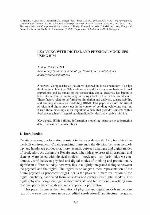
LEARNING WITH DIGITAL AND PHYSICAL MOCK-UPSUSING BIM
Andrzej ZARZYCKINew Jersey Institute of Technology, Newark, NJ, United [email protected]
Abstract. Computer-based tools have changed the focus and modes of designthinking in architecture. While often criticized for its overemphasis on formalexpressions and its pursuit of the spectacular, digital creativity has begun totake into account a multiplicity of design factors that define architecture.These factors relate to performance simulation and analysis, constructability,and building information modelling (BIM). This paper discusses the use ofphysical and digital mock-ups in the context of building technology courses.It uses these mock-ups as an important vehicle that provides students with afeedback mechanism regarding often digitally idealized creative thinking.
Keywords. BIM; building information modelling; parametric constructiondetails; construction assemblies.
1. Introduction
Creating-making is a formative constant in the ways design thinking translates intothe built environment. Creating-making transcends the division between technol-ogy and handmade products or, more recently, between analogue and digital modesof production. As during the Renaissance, when ideas expressed in drawings andsketches were tested with physical models1 – mock-ups – similarly today we con-tinuously shift between physical and digital modes of thinking and production. Asignificant difference today, however, lies in a tightly integrated dialogue betweenthe physical and the digital. The digital is no longer a mere representation of thefuture physical (a proposed design), nor is the physical a mere realization of thedigital creativity, fabricated from scale-less and context-less digital models. Thedigital-physical design dialogue is more intricate and bidirectional, involving sim-ulations, performance analyses, and component optimization.
This paper discusses the integration of physical and digital models in the con-text of the structure course in an accredited (professional) architectural program.
R. Stouffs, P. Janssen, S. Roudavski, B. Tunçer (eds.), Open Systems: Proceedings of the 18th InternationalConference on Computer-Aided Architectural Design Research in Asia (CAADRIA 2013), 323–332. © 2013,The Association for Computer-Aided Architectural Design Research in Asia (CAADRIA), Hong Kong, andCenter for Advanced Studies in Architecture (CASA), Department of Architecture-NUS, Singapore.
323
3B-111.qxd 4/28/2013 4:04 AM Page 323
It presents the student work that explores the design possibilities of a chosen struc-tural system with the use of parametric and behaviour-based computationalmodelling. It uses the mock-up as a vehicle to study, optimize, and evaluate thedesign as well as to provide feedback for student learning. Finally, it investigates dig-ital-to-physical design translations, the importance of which becomes more and morecritical in the context of the current, computer-intensive education of architects.
2. Class Methodology
The class approach employed a long tradition of using physical models to evalu-ate design ideas.2 However, this long tradition has a new variable – computation –that opens unique design opportunities and resolves some limitations associatedwith the use of physical models as design evaluators in the past.
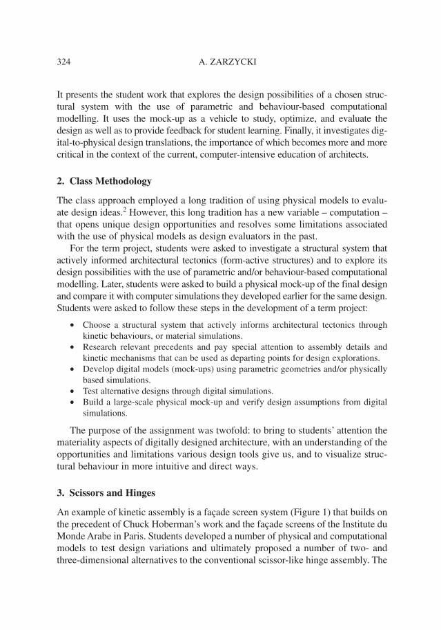
For the term project, students were asked to investigate a structural system thatactively informed architectural tectonics (form-active structures) and to explore itsdesign possibilities with the use of parametric and/or behaviour-based computationalmodelling. Later, students were asked to build a physical mock-up of the final designand compare it with computer simulations they developed earlier for the same design.Students were asked to follow these steps in the development of a term project:
• Choose a structural system that actively informs architectural tectonics throughkinetic behaviours, or material simulations.
• Research relevant precedents and pay special attention to assembly details andkinetic mechanisms that can be used as departing points for design explorations.
• Develop digital models (mock-ups) using parametric geometries and/or physicallybased simulations.
• Test alternative designs through digital simulations.• Build a large-scale physical mock-up and verify design assumptions from digital
simulations.
The purpose of the assignment was twofold: to bring to students’ attention themateriality aspects of digitally designed architecture, with an understanding of theopportunities and limitations various design tools give us, and to visualize struc-tural behaviour in more intuitive and direct ways.
3. Scissors and Hinges
An example of kinetic assembly is a façade screen system (Figure 1) that builds onthe precedent of Chuck Hoberman’s work and the façade screens of the Institute duMonde Arabe in Paris. Students developed a number of physical and computationalmodels to test design variations and ultimately proposed a number of two- andthree-dimensional alternatives to the conventional scissor-like hinge assembly. The
324 A. ZARZYCKI
3B-111.qxd 4/28/2013 4:04 AM Page 324
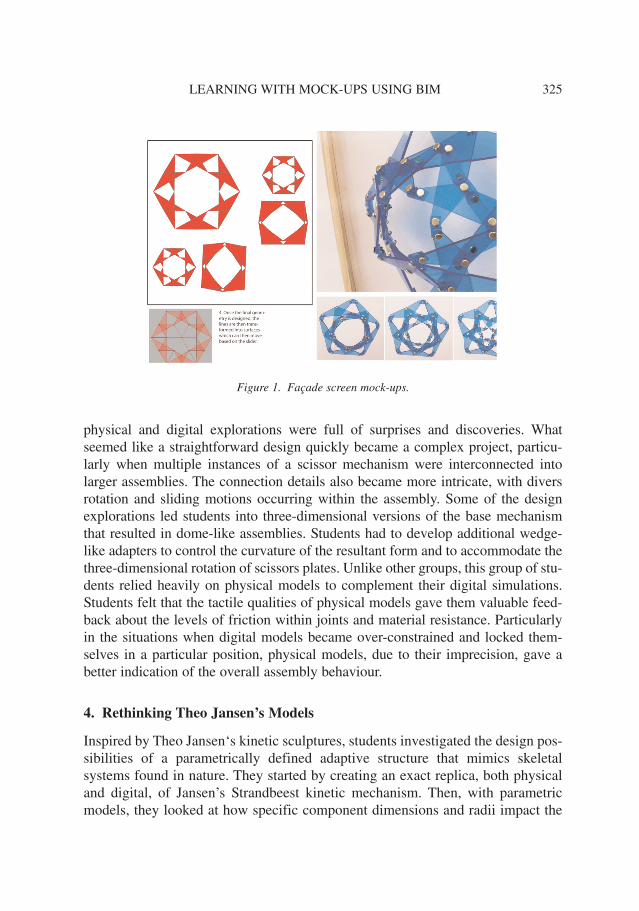
physical and digital explorations were full of surprises and discoveries. Whatseemed like a straightforward design quickly became a complex project, particu-larly when multiple instances of a scissor mechanism were interconnected intolarger assemblies. The connection details also became more intricate, with diversrotation and sliding motions occurring within the assembly. Some of the designexplorations led students into three-dimensional versions of the base mechanismthat resulted in dome-like assemblies. Students had to develop additional wedge-like adapters to control the curvature of the resultant form and to accommodate thethree-dimensional rotation of scissors plates. Unlike other groups, this group of stu-dents relied heavily on physical models to complement their digital simulations.Students felt that the tactile qualities of physical models gave them valuable feed-back about the levels of friction within joints and material resistance. Particularlyin the situations when digital models became over-constrained and locked them-selves in a particular position, physical models, due to their imprecision, gave abetter indication of the overall assembly behaviour.
4. Rethinking Theo Jansen’s Models
Inspired by Theo Jansen‘s kinetic sculptures, students investigated the design pos-sibilities of a parametrically defined adaptive structure that mimics skeletalsystems found in nature. They started by creating an exact replica, both physicaland digital, of Jansen’s Strandbeest kinetic mechanism. Then, with parametricmodels, they looked at how specific component dimensions and radii impact the
LEARNING WITH MOCK-UPS USING BIM 325
Figure 1. Façade screen mock-ups.
3B-111.qxd 4/28/2013 4:04 AM Page 325
kinetic behaviour of the entire system. Parametric definitions allowed for fluidchanges to a digital model and for immediate feedback on its kinetic behaviour.This helped students to understand the role individual elements played within theentire assembly and the types of motions these elements were capable to produce.These explorations led students to propose and develop an adaptable verticallyclimbing mechanism that used core principles of Jansen’s models with changes tothe types of constraints and possible motions.
Kinetic designs such as Jansen’s sculptures that mimic walking structures, orHoberman’s expanding dome, require close and detailed understanding of kineticmechanisms developed over time with multiple prototypes. Similar developmentswould not be easily achieved within a semester-long three-credit course. To short-cut the discovery process, students started with an already established design, inthis case Jansen’s walking mechanism, and investigated ways the logic for thisparticular mechanism can be extended to other forms of movement. While a phys-ical prototype was an ultimate goal for the project, it was easier to experiment withvariations of the base mechanism using digital modelling. However, conventionalthree-dimensional modelling software would not be an effective environment forprototyping. What was required for this particular project was parametric softwarethat would deal with constraints and be able to pass them between various com-ponents. Revit (parametric BIM) and Grasshopper (graphical algorithm editor forRhino) were suitable software environments for this project.
5. Kinetic Wings
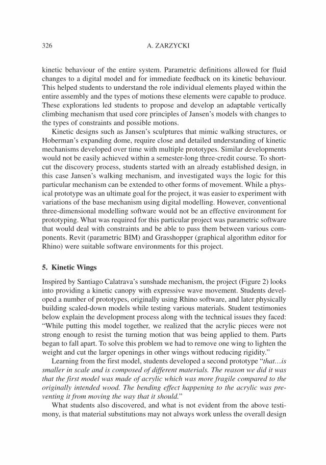
Inspired by Santiago Calatrava’s sunshade mechanism, the project (Figure 2) looksinto providing a kinetic canopy with expressive wave movement. Students devel-oped a number of prototypes, originally using Rhino software, and later physicallybuilding scaled-down models while testing various materials. Student testimoniesbelow explain the development process along with the technical issues they faced:“While putting this model together, we realized that the acrylic pieces were notstrong enough to resist the turning motion that was being applied to them. Partsbegan to fall apart. To solve this problem we had to remove one wing to lighten theweight and cut the larger openings in other wings without reducing rigidity.”
Learning from the first model, students developed a second prototype “that…issmaller in scale and is composed of different materials. The reason we did it wasthat the first model was made of acrylic which was more fragile compared to theoriginally intended wood. The bending effect happening to the acrylic was pre-venting it from moving the way that it should.”
What students also discovered, and what is not evident from the above testi-mony, is that material substitutions may not always work unless the overall design
326 A. ZARZYCKI
3B-111.qxd 4/28/2013 4:04 AM Page 326
or the design of individual components is appropriately adjusted. For example, asubstitution from wood to acrylic may require changing the thickness of elementsor redesigning their profiles to increase rigidity. Similarly, the impact on the fric-tion associated with the component rotation should be considered.
6. Umbrellas
Another kinetic project used an umbrella mechanism as a departure point for adap-tive structure. Starting by recreating an umbrella mechanism using the Revitsoftware, students linked individual assembly components with explicitly geo-metric relationships (trigonometric functions/expressions). Students focused ondeveloping design alternatives to the basic mechanism that investigated differentforms of hinging of components and folding of the overall design. Part of thedesign and production focus went into mechanical controls of the mock-up withan Arduino microcontroller and sensors, in a similar way as the canopy projectmentioned earlier did. In this case, the aperture of the umbrella was correlatedwith the light sensors positioned immediately below it.
Both projects, the canopy and the umbrella, used a simple mechanical precedentas the initial idea for the kinetic assemblies. While the final designs did not substan-tially redefine the initial prototypes, they were valuable learning experiences. Theytaught students the intricacies of kinetic architectural assemblies that predominantlyrely on simple ball joints or hinge-like mechanisms. They also allowed students to re-examine the purpose of kinetic structures and tie them in with a broader conceptualframework of adaptive designs and intelligent buildings. Furthermore, by laying outthe framework for microcontroller operability – if-else conditional statements – theywere able to define a series of functional responses to a single parameter input.
7. Pneumatic Doughnuts
While a mock-up as a partial full-size prototype can be easily achieved withkinetic structures by building a portion of the overall design, with pneumatic
LEARNING WITH MOCK-UPS USING BIM 327
Figure 2. Façade screen digital and physical mock-ups.
3B-111.qxd 4/28/2013 4:04 AM Page 327
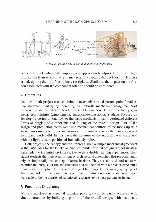
(air-supported) designs a partial mock-up may not be as effective. One needs acritical mass of the “building” to have both structural integrity and air tightness.This limitation resulted in pneumatic mock-ups encompassing almost the entiredesign scope. The “doughnut” in Figure 3 (A and D) is an example of a pneumaticstructure developed by students that went from a partial analysis and a mock-upinto a full-blown prototype. Students envisioned it as a free-standing pavilion ableto accommodate human activities in an unrestricted and comfortable way. Themotivation behind the centrally organized form of a doughnut was to create aspace that could be explored and also would allow for congregation. It appearedduring the initial small-scale model experimentations that the overly linear spacewould provide the difficulty of uniformly inflating it, particularly if one were torely on a single point, or not more than two points, of air supply.
Students started their project by developing initial three-dimensional geometryin Rhino software and fine-tuning its form, considering what a pneumatic structurewould most likely look like.3 Then they used the Kangaroo plug-in for Rhino andGrasshopper to simulate the physical behaviour of initial designs. During simula-tions, geometries with individual mesh cells were adaptively refined until anoptimized form was achieved. Since the original Rhino mesh was an inert geome-try (poly mesh) without any parametric controls, the resulting Kangaroo simulationwas not as effective from a design point of view as compared to a parametricallycontrolled mesh that could be interactively changed during simulation. For this rea-son, students moved from the Rhino inert mesh approach to Grasshopper’sparametric surface modelling environment and were able to explore a wide range
328 A. ZARZYCKI
Figure 3. Pneumatic structure digital explorations and physical mock-ups.
3B-111.qxd 4/28/2013 4:04 AM Page 328
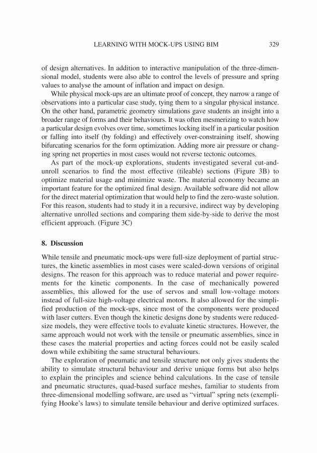
of design alternatives. In addition to interactive manipulation of the three-dimen-sional model, students were also able to control the levels of pressure and springvalues to analyse the amount of inflation and impact on design.
While physical mock-ups are an ultimate proof of concept, they narrow a range ofobservations into a particular case study, tying them to a singular physical instance.On the other hand, parametric geometry simulations gave students an insight into abroader range of forms and their behaviours. It was often mesmerizing to watch howa particular design evolves over time, sometimes locking itself in a particular positionor falling into itself (by folding) and effectively over-constraining itself, showingbifurcating scenarios for the form optimization. Adding more air pressure or chang-ing spring net properties in most cases would not reverse tectonic outcomes.
As part of the mock-up explorations, students investigated several cut-and-unroll scenarios to find the most effective (tileable) sections (Figure 3B) tooptimize material usage and minimize waste. The material economy became animportant feature for the optimized final design. Available software did not allowfor the direct material optimization that would help to find the zero-waste solution.For this reason, students had to study it in a recursive, indirect way by developingalternative unrolled sections and comparing them side-by-side to derive the mostefficient approach. (Figure 3C)
8. Discussion
While tensile and pneumatic mock-ups were full-size deployment of partial struc-tures, the kinetic assemblies in most cases were scaled-down versions of originaldesigns. The reason for this approach was to reduce material and power require-ments for the kinetic components. In the case of mechanically poweredassemblies, this allowed for the use of servos and small low-voltage motorsinstead of full-size high-voltage electrical motors. It also allowed for the simpli-fied production of the mock-ups, since most of the components were producedwith laser cutters. Even though the kinetic designs done by students were reduced-size models, they were effective tools to evaluate kinetic structures. However, thesame approach would not work with the tensile or pneumatic assemblies, since inthese cases the material properties and acting forces could not be easily scaleddown while exhibiting the same structural behaviours.
The exploration of pneumatic and tensile structure not only gives students theability to simulate structural behaviour and derive unique forms but also helpsto explain the principles and science behind calculations. In the case of tensileand pneumatic structures, quad-based surface meshes, familiar to students fromthree-dimensional modelling software, are used as “virtual” spring nets (exempli-fying Hooke’s laws) to simulate tensile behaviour and derive optimized surfaces.
LEARNING WITH MOCK-UPS USING BIM 329
3B-111.qxd 4/28/2013 4:04 AM Page 329
In these spring-net models, mesh edges are interpreted as springs, while vertexesare points where forces such as gravity are applied. The displacement of vertexesis controlled by a spring’s ability to expand, the tendency to return to its restingposition, and the amount of physical force (load) applied to individual points.Once all loads and spring properties are defined, the surface is going through self-normalizing reiterations and ultimately settles down in the optimized targettension state. By controlling the initial and the resting spring (edge) lengths, wecan simulate both stretching and contracting surfaces. This approach can be usedeffectively for tensile structures as well as for geometries that wrap around a groupof objects and produce a surface with a minimum volume.
9. What is Being Learned from Digital Versus Physical Mock-ups?
With today’s generation of students, who often have a better grasp of digital thanof physical tools, the requirement to manually construct designs is probably evenmore important than in the past. Since the architectural profession ultimately dealswith physically constructed buildings, there is a need for students to understand thetranslation process of their ideas from the digital to the physical. I have observedwith many students the perception that once design is modelled in a three-dimen-sional virtual environment, it is perceived as fully resolved. If it can exist in athree-dimensional model, it also has the right to exist in a physical setting. Whilethis may be true from the geometrical point of view, as compared to traditional two-dimensional representation of buildings where different drawings did not have tobe reconciled spatially, it is not true in other aspects of design. The present compu-tational tools solve some of these issues but still leave many of them unresolved.Specifically, material properties, physical behaviour, and contractibility continue toremain unaccounted for in most software packages. While the approach discussedabove points to ways of addressing the issues of material properties and physicalbehaviour, physical mock-ups prove to be an effective learning environment. Byconstructing kinetic designs or pneumatic structures, students experience the intri-cacies of mechanical assemblies and material limitations. The geometric precisiontaken for granted with software packages becomes a major issue when manuallyconstructing kinetic designs. Centre of gravity and points of rotation are importantfactors in the effective operation of kinetic assemblies. The process of building andrebuilding mock-ups, discovering imprecision in produced work, facilitates the dis-cussion on types of loads (concentric versus eccentric) and moments associatedwith them. Students experience firsthand the need for design tolerances and theways they can be incorporated in their designs. Overall, students moved away fromidealized computer-based reasoning toward more holistic thinking about a buildingas a probabilistic structure – a result of compounding imperfections and tolerances.
330 A. ZARZYCKI
3B-111.qxd 4/28/2013 4:04 AM Page 330
Similarly, material choices become critical when considering both types ofstructures, pneumatic and kinetic. In pneumatic designs, the weight of the mate-rial had to be offset by the applied pressure and the quality of seam welds. Designshad to strike a fine balance between a membrane (skin) and the underlying skele-ton, particularly in the air-inflated pneumatic structures that are supported bypressurized air within an inflated structural core. In the kinetic designs, the mate-rial-to-material interactions – friction – and fatigue become critical design drivers.Repetitive movements, rotational and lateral, quickly affect the material integrityand connections when applied for a longer period of time. This became evident ina number of projects that used wood-on-wood assemblies, where even a change inthe air humidity would affect component movements. While most of the mock-upswere realized with hand tools and traditional woodshop machinery, kinetic designshad to resort to laser cutting of the individual components. This in turn predefinedthe range of possible materials, with acrylic glass being the most effective fromthe standpoint of material durability and appearance.
10. Summary
While each case study project tackled a particular structural system with its own,often narrow, characteristics and concerns, as a group students dealt with a number ofimportant design issues that start to permeate into everyday architectural practices.Considerations of efficient material usage, or designing for kinetic and adaptive struc-tures, are just examples of challenges and opportunities associated with currentpractices. Probably the most important lesson came from the student hands-oninvolvement in creating-making their own designs. It is rare in the course of archi-tectural education that students have an opportunity to test and realize their owncreative ideas, albeit in an abbreviated mock-up-sized magnitude. The built mock-upsin most cases differed from the original ideas. While building them, students wentthrough a give-and-take process of negotiating initial design aspirations against mate-rial and structural considerations. This back-and-forth process, culminating withbuilding a physical mock-up, provided students with an important feedback mecha-nism regarding their often digitally idealized creative thinking. I found that buildingphysical and digital mock-ups, and reconciling emerging differences, effectively sit-uated design challenges and provided vehicles for their resolution.
Endnotes
1. As evident in Filippo Brunelleschi’s work, among others.2. One of the areas where physics-based form finding is used in architecture is in the design of ten-
sile structures such as tents and cable nets as well as pneumatic struc-tures. Small-scale modelsusing canvas, chains (Antoni Gaudí), and soap films (Frei Otto) have been used to derive these
LEARNING WITH MOCK-UPS USING BIM 331
3B-111.qxd 4/28/2013 4:04 AM Page 331
surfaces, since they approximate minimal-tension surfaces. However, measurements and con-trols of these models can be difficult, in addition to material and scale differences that make anymeasurements only partially useful.
3. The reason for “pre-cooking” the simulation – starting with the geometry that is close to a finalpneumatic model – was to minimize time and avoid simulation artefacts. In some cases when opti-mizing more extreme shapes, such as a highly wrinkled form, even after a relatively longsimulation time there were still residual elements of the original wrinkles in a simulated geometry.
References
Ambrose, M.: 2009, Agent Provocateur – BIM and the Design Studio: Questioning Roles ofAbstraction and Simulation in Design Education, in P. Crisman and M. Gillem (eds.), The Valueof Design, ACSA, New York, 85.
Otto, F. and Rasch, B.: 2001, Finding Form: Towards an Architecture of the Minimal, Axel Menges.Hannu, P.: 2007, Early Architectural Design and BIM, in A. Dong, A. Vande Moere and J. S. Gero
(eds.), Proceedings of the CAADFutures’07, Springer, 291–302.Wallick, K and Zaretsky, M.: 2009, Fragmentation and Interrogation as an Approach to Integration,
in P. Crisman and M. Gillem (eds.), The Value of Design, ACSA, New York.Zarzycki, A.: 2009, Dynamics-based tools: an unusual path to design integration, Proceedings of the
ACM SIGGRAPH ASIA 2009 Educators Program, ACM, New York.Zarzycki, A.: 2011, Form-making Without Form Making, Proceedings of the Parametricism (SPC)
ACADIA Regional 2011 Conference, Lincoln, NE.
332 A. ZARZYCKI
3B-111.qxd 4/28/2013 4:04 AM Page 332