Embed Size (px)
Citation preview
Learning to Control Reconfigurable Staged Soft Arms
Austin Nicolai1, Gina Olson1, Yigit Menguc1,2, Geoffrey A. Hollinger1
Abstract— In this work, we present a novel approach formodeling, and classifying between, the system load statesintroduced when constructing staged soft arm configurations.Through a two stage approach: (1) an LSTM calibration routineis used to identify the current load state then (2) a control inputgeneration step combines a generalized quasistatic model withthe learned load model. Our experiments show that accountingfor system load allows us to more accurately control taperedarm configurations. We analyze the performance of our methodusing soft robotic actuators and show it is capable of classifyingbetween different arm configurations at a rate greater than95%. Additionally, our method is capable of reducing the end-effector error of quasistatic model only control to within 1 cmof our controller baseline.
I. INTRODUCTION
Compared to traditional rigid robots, soft robots providea unique set of challenges and benefits for applications inlow load, high flexibility tasks. Soft robots are used acrossa variety of domains, including grasping [1], [2], prostheticdevices [3], [4], and biologically inspired locomotion [5],[6], [7], [8]. A common morphology seen in soft robots forthese applications is a long, thin bending arm. Soft bendingarms are most commonly constructed with three or morelongitudinal actuators in parallel, where bending is controlledby lengthening or shortening actuators. Biological systems,such as octopuses, use a similar arm architecture, with thearm tapering towards the tip [9]. This tapering allows fora trade-off between strength (near the base) and flexibility(near the tip). Current state-of-the-art dynamic models forsoft bending arms require experimental fits to determine theirphysical parameters. While these are suitable for controllingindividual arms, varying the arm configuration requires anew set of parameters to be determined. A more generalizedmodel is desirable to take advantage of the fact that armconfigurations comprised of multiple link segments can bereconfigured to suit different scenarios. The quasistatic modelproposed in [10] combines conservation of energy with staticequilibrium to provide a generalizable formulation; however,this formulation assumes an unloaded arm.
In order to work with the types of staged arm architecturespreviously mentioned, we need to be able to account forthe system load introduced when connecting multiple lon-gitudinal actuators in sequence. In this work, we proposean approach that augments the generalizable model in [10]
This work was funded in part by the National Science FoundationNational Robotics Initiative (NSF NRI award IIS-1734627).
1Collaborative Robotics and Intelligent Systems (CoRIS) Institute, Ore-gon State University, Corvallis, Oregon 97331
2Facebook Reality Labs, Redmond, WashingtonAuthors’ email: {nicolaia, olsongi, yigit.menguc,
geoff.hollinger}@oregonstate.edu
with a data-driven, learned load model that accounts forthe violation of the no-load assumption. With this approach,no additional learning or parameter fitting is required whenswitching between arm configurations. Another benefit is thatthe generalizable model provides a lower bound for our inputcontrol pressures that would otherwise not be available whenlearning the entire control model. In our approach, we firstdetermine the staged arm configuration in use via a longshort-term memory (LSTM) based, single-shot calibrationroutine using an OptiTrack system. After calibration, onlysimple pressure based on-off control is required to control thearm. We validate the proposed approach on multiple stagedsoft arms showing that it is able to accurately identify the armconfiguration in use. Additionally, we show that the learnedload model is able to compensate for the system load acrossvarious staged arm configurations.
In summary, we present a novel control architecture forreconfigurable staged soft arms that:
• Compensates for the system load introduced when con-necting multiple longitudinal soft actuators in sequence.
• Leverages the temporal nature of the arm motion toaccurately identify the current arm configuration.
• Requires no additional learning or parameter fittingwhen switching between arm configurations.
The remainder of this paper is organized as follows. Wediscuss related kinematic modeling and data-driven controlmethods in Section II. Next, we describe our proposedapproach in Section III. Our experiments and their results arepresented in Section IV. Finally, we conclude and proposeavenues for future work in Section V.
II. RELATED WORK
In soft robotics, kinematic modeling approaches com-monly utilize the constant curvature approximation. Anoverview of these techniques are presented by Webster andJones [11]. When actuator characteristics can be more easilymeasured (e.g., cable driven arms) more precise geometricmodels can be used [12], [13]. Controllers that incorporatesensory feedback have also been proposed, including bothsingle camera [14] and multiple camera [15] controllers.
In recent years, many data-driven learning based ap-proaches have been proposed for controlling soft robots.An early model-free implementation of a static controllerwas proposed by Giorelli et al. in which the inverse staticsof a cable driven soft robot were directly learned with aneural network [16]. This approach was validated on physicalhardware for a 2 degree of freedom (DoF) [17] and 3 DoF[18] soft manipulator and was shown to outperform the morecomplex model used for comparison. An approach learning

the inverse kinematics of a soft robot was presented byThurunthel et al. in [19], [20]. In this approach, the problemwas formulated as a differential inverse kinematics problemusing local mapping which allows for multiple solutionsglobally. More recently, Thurunthel et al. have proposed anapproach that additionally incorporates end-effector feedbackfor learning the inverse kinematics [21]. They show that theiralgorithm can deal with stochasticity and exhibits adaptivebehavior in an unstructured environment. Finally, Bruder etal. have proposed using Koopman operator theory to learnlinear dynamical models for a non-linear soft robot arm [22].The benefit to this method is that in the lifted linear state,the optimization problem is convex allowing for use withmodel predictive control techniques. While these data-drivenmethods perform well, they do not extend to generalizablearm configurations which is desirable for reconfigurablestaged arm architectures.
In addition to solely data-driven methods, hybrid con-trollers that combine both model-based and model-free ap-proaches have been proposed. Jiang et al. have proposed ahybrid approach that first uses a cost function to transformbetween task and configuration space [23]. Once a pose hasbeen identified, a neural network is used to map curvatureand arc length to control pressures. Another approach pro-posed by Reinhart et al. observes that errors in the constantcurvature model reduce the accuracy of the inverse kinematiccontroller [24]. To reduce this error, they model the errorwith a neural network and show that their hybrid method iscapable of reducing tracking error for their arm. In our workwe use a similar hybrid technique, but rather than learning tocompensate for real world model error, we learn a load modelthat allows us to further generalize the quasistatic modelpresented in [10] to various staged soft arm configurations.
III. METHOD
The quasistatic model proposed in [10] is capable ofproviding a mapping between control input and soft arm
states for individual unloaded link segments as given by
u = Pqs(κ, t), (1)
where Pqs represents the quasistatic model and u, κ, and trepresent the input control pressure, soft arm state, and softarm width, respectively. In our proposed approach, we learn amodel for the system load introduced when combining theseindividual link segments into a staged arm configuration.Following the previous notation, this extends our mappingfunction to
ut = Pqs(κ, t) + Ploadt(s, κ), (2)
where t represents the width of a given link segment in thestaged arm and ut, Ploadt , and s represent the input controlpressure, learned load model, and load state for the linksegment of width t, respectively. We note that a load state isdefined for each link segment in an arm configuration, and(in this work) does not change over time.
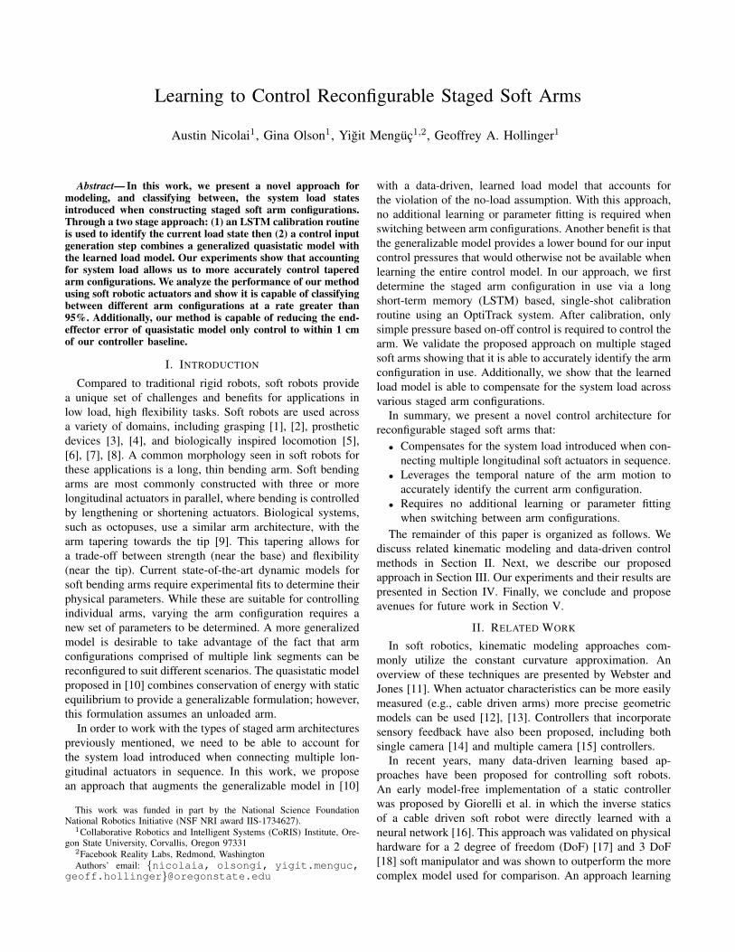
Our approach uses a fully connected deep network to learnthe load model and an LSTM to identify the current loadstate. While all arm configurations in this work are usedduring training, in general only a subset of all possible armconfigurations (equal to the number of unique load states)need to be used. A block diagram overview of our systemcan be seen in Figure 1.
A. Load State Estimation
Every arm configuration used in this work produces aunique load state for each link segment in the arm. Thisallows us to characterize the load state for each link segmentby simply determining which arm configuration is currentlyin use. Additionally, this enables us to identify the currentconfiguration by only looking at the base link of the arm.
We classify which configuration the arm is in by lookingat how the base link control input, ubase, and state, κbase,change with respect to time. In the absence of externaldisturbances, κbase changes smoothly as ubase is increased.
Fig. 1: A block diagram of the architecture proposed in this work. The single-shot calibration routine is only performedonce per arm. During operation, real-time pressure control is performed for each individual link segment in the arm. Foreach segment, an input control pressure is generated using the predicted load state and desired arm curvature state (goal κ).Only the calibration routine requires use of the OptiTrack system.

The result of this is that the pair (ubase, κbase)i is highlypredictive of the pair (ubase, κbase)i+1. As such, we usean LSTM based network for classification. To do this, weperform a single-shot calibration routine using an OptiTracksystem. This calibration routine is comprised of a singlesweep of the arm through its entire valid pressure range.During this sweep, (ubase, κbase) pairs are obtained from theOptiTrack and actuators, respectively. These pairs of data arepassed into the LSTM after which a configuration predictionis produced by selecting the class with highest probability.
Since an entire arm sweep is used as classification input,it is time prohibitive to acquire training data solely by hand.Instead, we augment our data by stitching together segmentsof recorded sweeps to form training sweeps, as detailed inAlgorithm 1. In directly stitching these segments togetherwithout smoothing, we’re able to approximate real worlddisturbances (e.g., friction, manufacturing imperfections) al-lowing our classifier to be more robust.
B. Control Input MappingWe decompose the problem of mapping soft arm states
to control inputs into a quasistatic model mapping and loadmapping: ut = Pqs(κ, t) + Ploadt
(s, κ). This has severalbenefits. In the planar case, adding a load to the system willincrease the control pressure required to achieve a given linkcurvature state. This means the quasistatic model provides uswith a lower bound for the control input. In only learninga portion of the overall state to control input mapping, weminimize the potential impact of incorrect predictions by thenetwork. Since the actuator upper bound pressure ratings areknown, we can guarantee a safe control input.
Algorithm 1: Training Data Generation// recorded: recorded data sequences
// N: training sequences to generate
// training: generated data sequences
Input: recorded, NOutput: training// set of all possible segment lengths
seg len = {20% 30% 40%}for i = 1 to N do
start idx = 0% // beginning of sequence
while start idx < 100% dolen
R← seg len // randomly select
seqR← recorded // randomly select
end idx = start idx + lenif end idx ≥ 100% then
end idx = 100% // cut segment short
end// append the segment to the generated
sequence and then update the index
segment = seq[start idx:end idx]trainingi.append(segment)start idx = end idx
endend
Quasistatic Model: The quasistatic model developedpreviously [10] assumes constant curvature (Figure 2), analways planar cross section and no loads applied to eachindividual arm segment. Only one actuator in each segmentis pressurized at a time. We calculate curvature by combiningmoment equilibrium and conservation of energy with akinematic constraint. The pressurized actuator generates aforce FP that is dependent on the known pressure P andunknown strain εP , while the passive actuator force FE
depends only on that actuator’s strain εE . The momentbalance for an arm of width t, summed about the unknownlocation of the neutral axis, hP is
ΣM = −FP (εP , P )(−hP )+(−FE(εE))(t−hP ) = 0. (3)
Each actuator has a stored strain energy UP and UE , and thepressurized actuator produces work WP . The energy balancefor each segment is
ΣE = WP (P, εP )− UP (εP )− UE(εE) = 0. (4)
The system of equations is closed through a kinematic rela-tionship, which relates the pressurized and passive actuatorsstrains geometrically:
εP = −hPκ, (5)
εE = (t− hP )κ. (6)
The actuator force, work and strain energy are calculatedfrom experimental force characterizations [10].
Load Model: In order to learn the mapping for the loadmodel we utilize a fully connected deep network. That is,
Ploadt(x) = f(Wx+ b), (7)
where the weight matrix, W , and offset vector, b, are learnedparameters; f(·) represents a non-linear activation function;and the input x is given by (s, κ). An individual deepnetwork is trained for each of the link segment widths usedin our arm configurations. We note that this scales linearlywith the number of link segment widths available. Increasingthe length of the overall arm (as measured in number of linksegments) does not require additional networks to be trained,but rather increases the number of load states to model.
Fig. 2: An illustration of the constant curvature assumption.

Training data is generated by recording the individual linksegment actuator pressure states at various curvatures. Thequasistatic model value is subtracted from the recorded pres-sure to obtain the load model value to learn. To efficientlygenerate training data, we perform arm sweeps that cover theentire valid pressure range of the actuators. This is beneficialbecause every sweep of the arm performs slightly differentlydue to an accumulator tube and real world noise (e.g., frictionand manufacturing imperfections). This slight performancevariation naturally obtains data samples at different curvaturevalues throughout the valid pressure range.
The entire training data set is generated by combiningall recorded data points into a single distribution. For eachlink width t, we have a set of load states, {s}, and a set ofrecorded data pairs, {u, κ}. We model this distribution as
ut = Ploadt(s,κ) +N(µ, σ2), (8)
where ut are the recorded input pressures for link width t,Ploadt(s,κ) is the true load model we wish to learn, andN(µ, σ2) approximates the real world noise observed.
IV. EXPERIMENTS AND RESULTS
We demonstrate the capability of our approach throughthree experiments. In all three experiments, we use fourdifferent link segment widths: 80 mm, 65 mm, 50 mm,and 35 mm. Staging these four widths in tapered config-urations (connected via 3D printed spacing plates) providesus with three unique arm configurations: 80-65-50mm, 80-65-35mm, and 80-50-35mm. Each arm segment is made oftwo actuators joined by six evenly spaced radial supportplates. Actuators were made using EcoFlex 00-30, had awall thickness of 1.5 mm, internal diameter of 6 mm, lengthof 240 mm, and were reinforced with polyester expandablesheathing (McMaster #9284K2). For full manufacturing de-tails, we refer the reader to [10]. Links were controlled usingreal-time feedback as detailed in Section IV-A.
In Experiment 1, we compare two classification methods:a fully connected deep network and an LSTM. We useprecision and recall as our metrics for success. In general,precision and recall are calculated as
Precision =Tp
Tp + Fp(9)
Recall =Tp
Tp + Fn, (10)
respectively, where Tp represents true positives, Fp repre-sents false positives, and Fn represents false negatives.
In Experiment 2, we measure accuracy in curvature spaceusing the mean and maximum error (with standard devia-tion). For each segment width, all load cases are averagedinto the reported metric. We compare several methods:
• Curvature Control (baseline) uses the OptiTrack sys-tem for state feedback, directly controlling the arm tothe desired curvature. This represents the maximumaccuracy of our controller.
• Individual Curve Fit Control uses individually fitcurves (6th order polynomial) to model each load state
of each segment width. This approach scales combina-torically with both the number of link widths and armconfigurations considered.
• Single Surface Fit Control uses a single surface fit(6th order polynomial) to model all load states for everysegment width. This approach scales linearly with thenumber of link widths.
• Deep Network Control uses a single trained deepnetwork to model all load states for each segment width.This also scales linearly with the number of link widths.
In Experiment 3, mean and maximum errors of the end-effector are reported in Euclidean space (with standarddeviation) to provide a more intuitive understanding of thequality of control. We compare three methods:
• Curvature Control (baseline) represents the maximumaccuracy of our controller.
• Quasistatic Model Only Control uses only the modelproposed in [10] to control the arms and does notaccount for load.
• Quasistatic Plus Load Model Control uses the pro-posed approach to control the arm, accounting for loadusing a fully connected deep network.
A. Hardware Setup
Full arm control was achieved by controlling individuallink segments with on-off feedback control. Our custom con-trol board is capable of both pressure and curvature controlvia real-time feedback. We note that our proposed approachoperates using only pressure feedback. Experiments 2 and3 compare against direct curvature control as a means ofcomparing against the maximum accuracy of our controller.
The control board is comprised of a diaphragm pump,solenoid valves, pressure sensors, and an Arduino. The singlediaphragm pump provides airflow to the entire system whilethe solenoid valves control whether or not individual linksegment actuators inflate, deflate, or maintain pressure. TheArduino controls the pump speed and solenoid states. MAT-LAB is used as to interface with both the control board andthe OptiTrack system. System feedback is available in twoforms: pressure and curvature. Pressure feedback is obtainedvia onboard Honeywell Basic ABP Series sensors. Curvaturefeedback is obtained from the positions of retroreflectivemarkers as given by the OptiTrack system.
B. Experiment 1: Configuration Classification Accuracy
We compare our proposed LSTM architecture againsta standard, fully connected deep architecture. While botharchitectures receive the same input data, the fully connectedarchitecture represents a brute force approach that doesn’texplicitly leverage the temporal nature of our data. Thespecific architecture parameters can be seen in Tables Iand II. The layer naming convention denotes both the type oflayer and number of units (i.e., lstm30 represents an LSTMlayer with 30 units). We train and validate on 600 and 150sweeps per arm configuration, respectively (total: 1800 and450). The networks were trained for up to 500 epochs (withearly stopping) using the Adam optimizer [25].

For each arm configuration, we perform 25 classificationtrials. Each trial involves placing the staged arm in theOptiTrack staging area and performing a single sweep ofthe base link segment’s full pressure range (0-12 psi). Therecorded (ubase, κbase) pairs are passed through the trainedclassifiers and the load state prediction for each link in thestaged arm, s, is given by the maximum class probability.
Full results from the experiment can be seen in Table IV.We can see that both network architectures were able toachieve high classification accuracy, with the LSTM slightlyoutperforming the fully connected deep network. In bothcases, the 80-65-50mm configuration was easiest to classify.This is likely because the 35 mm segment is the lightest, andit is easy to detect the configuration without that segment.Classifying between the 80-65-35mm and 80-50-35mm con-figurations proved more difficult as the difference in motionbetween them is more slight. An interesting result is thatthe LSTM network architecture required far fewer trainableparameters (11,373 vs. 250,883) and converged faster (287vs. 326 epochs) to achieve the reported results, highlightingthe benefit of explicitly leveraging the data temporality.
C. Experiment 2: Load Model AccuracyFor this experiment, ground truth load states are given to
both the deep network and surface fit to directly measure thequality of the load model learned. The deep network structurecan be seen in Table III. We train and validate on 1000 and200 data points per load case (total: 3000 and 600 for the80 mm segment, 2000 and 400 for the 65 mm segment, 1000and 200 for the 50 mm segment). The network was trainedfor up to 200 epochs using the Adam optimizer [25].
We control each loaded segment (i.e., all segments exceptthe 35 mm) to 25 distinct curvatures equally spaced alongthe segment’s range of motion. We note that this range ofmotion changes for each segment width and load condition,and thus different curvatures are chosen for each condition.
The results of this experiment can be seen in Table V.Here, we can see that direct curvature control provides avery accurate baseline. The individual curve fits and ourproposed method perform accurately (and similarly, exceptfor the 65 mm segment). While the performance is similar,the individual curve fit method scales combinatorically withthe number of link widths and arm configurations used.Despite the single surface fit performing the worst in allcases, the gap between it and other methods decreased as thenumber of load cases modeled decreased (i.e., segment widthdecreased). This makes sense since for fewer load cases, themodeling problem is more straightforward.
We observed the 65 mm segment to experience inconsis-tent performance in the low pressure region. Notably, thisaffected the performance (both mean and maximum errorrates) of the individual curve fits more than our proposedmethod. This is likely because the deep network inherentlymodels functions more complex than a 6th order polynomial.
D. Experiment 3: End-Effector AccuracyIn this experiment, we first perform the single-shot cali-
bration routine using only the LSTM classifier. The load state
prediction is then used for the remainder of the experiment,even if misclassified, so as to fully capture the accuracy of theproposed system. The load state and desired curvature stateare then used to generate control inputs, ut = Pqs(κgoal, t)+Ploadt
(s, κgoal) for each link in the arm configuration. Wecontrol the arm to 25 distinct, randomly generated arm stateswithin the reachable workspace for all arm configurationsand measure the resulting end-effector location.
Full results can be seen in Table VI. As expected, thecurvature control baseline is the most accurate. Even thoughthe mean error appears to be somewhat high, we note thatthis error largely comes from the shortening of the base curveof the link segments as they bend. While the control is highlyaccurate in curvature space (as shown in Experiment 2), asthe link bends and shortens, error is introduced along thesegment arc. This is further evidenced by the low standarddeviation in the results, demonstrating the consistency ofboth the baseline and our approach. The link shortening canbe seen in Fig. 3 and is further discussed in [10].
From the table, we can see that the quasistatic modelonly control performs poorly. This illustrates that withoutaccounting for the system load, the benefits of a staged armconfiguration (e.g., increased flexibility near the tip) cannotbe taken advantage of. This mode of control performs poorlyenough that it would not be suitable for many real worldtasks. As in Experiment 2, we can see that our proposedapproach performs closely to the curvature control baseline.For all arm configurations, our proposed method achieves anaccuracy within 1 cm of the curvature control baseline.
V. CONCLUSION
We presented a novel approach capable of learning tomodel the system load introduced when constructing taperedstaged soft arm configurations that is not accounted for inthe generalized kinematic model. Our proposed approach iscapable of modeling multiple load states allowing the stagedarms to be reconfigured with no additional training required.Experiments on soft robotic hardware show that our approachcorrectly identifies the arm configuration at a rate greaterthan 95%. Additionally, our method reduces the end-effectorerror of quasistatic model only control to within 1 cm of ourcontroller baseline. Our approach enables the use of taperedstaged arm configurations allowing us to take advantage oftheir increased flexibility.
These results suggest a couple of avenues for future work.First, the classification step can be extended to predict a seg-ment’s general load state by changing the LSTM predictionfrom classification to regression. This would allow the armto work with arbritrary external loads (e.g., manipulating anobject). Second, to further increase the real world capabili-ties, we can incorporate soft sensors on the individual linksegments. Link segment curvature feedback can be obtainedfrom these, removing the need for the OptiTrack system.
VI. ACKNOWLEDGMENTS
We would like to thank Scott Chow and ChristopherBollinger for their help troubleshooting code.

TABLE I: LSTMClassifier Architecture
Layer Activation Dropoutlstm30 ReLU ∼lstm30 ReLU ∼dense3 Softmax ∼
TABLE II: Fully ConnectedClassifier Architecture
Layer Activation Dropoutdense512 ReLU 20%dense256 ReLU 20%dense64 ReLU 20%dense3 Softmax ∼
TABLE III: Fully ConnectedLoad Model Architecture
Layer Activation Dropoutdense128 ReLU 10%dense32 ReLU 10%dense1 Linear ∼
TABLE IV: Classification Accuracy Results. Both the mean and individual class metrics arereported. The individual classes are specified by the arm configuration details (mm).
Precision RecallMean 80-65-50 80-65-35 80-50-35 Mean 80-65-50 80-65-35 80-50-35
Fully Connected 94.85% 100.0% 88.89% 95.65% 94.67% 100.0% 96.0% 88.0%LSTM (proposed) 97.33% 100.0% 96.0% 96.0% 97.33% 100.0% 96.0% 96.0%
TABLE V: Individual Link Control Accuracy Results. Details regarding each method listed can be found in Section IV.
80 mm Segment 65 mm Segment 50 mm SegmentMean
Error (m−1)Max
Error (m−1)Mean
Error (m−1)Max
Error (m−1)Mean
Error (m−1)Max
Error (m−1)Curvature Control(baseline) 0.015 ± 0.011 0.047 0.022 ± 0.016 0.062 0.026 ± 0.017 0.079
Individual CurveFit Control 0.037 ± 0.021 0.086 0.189 ± 0.152 0.552 0.076 ± 0.047 0.160
Single SurfaceFit Control 0.071 ± 0.041 0.175 0.204 ± 0.177 0.551 0.082 ± 0.052 0.194
Deep NetworkControl (proposed) 0.037 ± 0.028 0.123 0.103 ± 0.108 0.403 0.072 ± 0.041 0.154
TABLE VI: Full Arm Control Accuracy Results. Details regarding each method listed can be found in Section IV.
80-65-50mm Configuration 80-65-35mm Configuration 80-50-35mm ConfigurationMean
Error (cm)Max
Error (cm)Mean
Error (cm)Max
Error (cm)Mean
Error (cm)Max
Error (cm)Curvature Control(baseline) 2.791 ± 0.380 3.386 3.342 ± 0.402 4.099 3.672 ± 0.626 5.103
Quasistatic ModelOnly Control 9.215 ± 5.535 17.267 9.572 ± 5.484 18.171 8.110 ± 4.457 15.162
Quasistatic Plus LoadModel Control (proposed) 3.468 ± 0.512 4.490 3.9282 ± 0.602 5.339 4.125 ± 0.698 5.479
(a) Curvature control (b) Quasistatic model only control (c) Quasistatic plus load model control
Fig. 3: A comparison of the end-effector error produced by the control methods in Experiment 3. In each image, the theoreticalexpected end-effector location (before link shortening) is represented by the orange square. The three dots represent the finalend-effector location for the different control methods. Curvature control is represented by the green dot, quasistatic modelonly control is represented by the magenta dot, and quasistatic plus load model control is represented by the red dot.

REFERENCES
[1] H. Zhao, K. O’Brien, S. Li, and R. Shepherd, “Optoelectronicallyinnervated soft prosthetic hand via stretchable optical waveguides,”Science Robotics, vol. 1, no. 1, 2016.
[2] M. Manti, T. Hassan, G. Passetti, N. D’Elia, C. Laschi, andM. Cianchetti, “A bioinspired soft robotic gripper for adaptable andeffective grasping,” Soft Robotics, vol. 2, no. 3, pp. 107–116, 2015.
[3] G. Singh, C. Xiao, G. Krishnan, and E. Hsiao-Wecksler, “Designand analysis of soft pneumatic sleeve for arm orthosis,” Proc. ASMEInternational Design Engineering Technical Conferences & Computersand Information in Engineering Conference, 2016.
[4] P. Polygerinos, S. Lyne, Z. Wang, L. F. Nicolini, B. Mosadegh,G. M. Whitesides, and C. J. Walsh, “Towards a soft pneumatic glovefor hand rehabilitation,” Proc. IEEE/RSJ International Conference onIntelligent Robots and Systems, pp. 1512–1517, 2013.
[5] T. Umedachi, V. Vikas, and B. Trimmer, “Softworms: The design andcontrol of non-pneumatic, 3D-printed, deformable robots,” Bioinspi-ration & Biomimetics, vol. 11, no. 2, p. 025001, Mar 2016.
[6] C. Branyan, C. Fleming, J. Remaley, A. Kothari, K. Tumer, R. Hatton,and Y. Menguc, “Soft snake robots: Mechanical design and geomet-ric gait implementation,” Proc. IEEE Conference on Robotics andBiomimetics (RoBio 2017), pp. 282–289, 2017.
[7] H. Lin, G. G. Leisk, and B. Trimmer, “GoQBot: A caterpillar-inspiredsoft-bodied rolling robot,” Bioinspiration & Biomimetics, vol. 6, no. 2,p. 026007, Apr 2011.
[8] M. Calisti, E. Falotico, and C. Laschi, “Hopping on uneven terrainswith an underwater one-legged robot,” IEEE Robotics and AutomationLetters, vol. 1, pp. 461–468, 2016.
[9] W. Kier and K. Smith, “Tongues, tentacles and trunks: The biome-chanics of movement in muscular-hydrostats,” Zoological Journal ofthe Linnean Society, vol. 83, no. 4, pp. 307–324, 1985.
[10] G. Olson, S. Chow, A. Nicolai, C. Branyan, G. Hollinger, andY. Menguc, “A generalizable equilibrium model for bending soft armswith longitudinal actuators,” The International Journal of RoboticsResearch, DOI:10.1177/0278364919880259, Oct. 2019.
[11] R. J. Webster and B. A. Jones, “Design and kinematic modeling ofconstant curvature continuum robots: A review,” The InternationalJournal of Robotics Research, vol. 29, no. 13, pp. 1661–1683, 2010.
[12] F. Renda, M. Cianchetti, M. Giorelli, A. Arienti, and C. Laschi, “A3D steady-state model of a tendon-driven continuum soft manipulatorinspired by the octopus arm,” Bioinspiration & Biomimetics, vol. 7,no. 2, p. 025006, May 2012.
[13] F. Renda, M. Giorelli, M. Calisti, M. Cianchetti, and C. Laschi,“Dynamic model of a multibending soft robot arm driven by cables,”IEEE Transactions on Robotics, vol. 30, no. 5, pp. 1109–1122, Oct2014.
[14] J. M. Croom, D. C. Rucker, J. M. Romano, and R. J. Webster,“Visual sensing of continuum robot shape using self-organizing maps,”Proc. IEEE International Conference on Robotics and Automation, pp.4591–4596, 2010.
[15] D. B. Camarillo, C. R. Carlson, and J. K. Salisbury, “Configurationtracking for continuum manipulators with coupled tendon drive,” IEEETransactions on Robotics, vol. 25, no. 4, pp. 798–808, 2009.
[16] M. Giorelli, F. Renda, G. Ferri, and C. Laschi, “A feed-forward neuralnetwork learning the inverse kinetics of a soft cable-driven manipulatormoving in three-dimensional space,” Proc. IEEE/RSJ InternationalConference on Intelligent Robots and Systems, pp. 5033–5039, 2013.
[17] M. Giorelli, F. Renda, M. Calisti, A. Arienti, G. Ferri, and C. Laschi,“Neural network and jacobian method for solving the inverse staticsof a cable-driven soft arm with nonconstant curvature,” IEEE Trans-actions on Robotics, vol. 31, no. 4, pp. 823–834, Aug 2015.
[18] ——, “Learning the inverse kinetics of an octopus-like manipulatorin three-dimensional space,” Bioinspiration & Biomimetics, vol. 10,no. 3, p. 035006, May 2015.
[19] T. Thuruthel, E. Falotico, M. Cianchetti, and C. C. Laschi, “Learningglobal inverse kinematics solutions for a continuum robot,” in RO-MANSY 21 - Robot Design, Dynamics and Control, V. Parenti-Castelliand W. Schiehlen, Eds. Cham, Switzerland: Springer InternationalPublishing, 2016, pp. 47–54.
[20] T. Thuruthel, E. Falotico, M. Cianchetti, F. Renda, and C. Laschi,“Learning global inverse statics solution for a redundant soft robot,”Proc. 13th International Conference on Informatics in Control, Au-tomation and Robotics, pp. 303–310, 2016.
[21] T. Thuruthel, E. Falotico, M. Manti, A. Pratesi, M. Cianchetti, andC. Laschi, “Learning closed loop kinematic controllers for continuummanipulators in unstructured environments,” Soft Robotics, vol. 4,no. 3, pp. 285–296, 2017.
[22] D. Bruder, B. Gillespie, C. D. Remy, and R. Vasudevan, “Modelingand control of soft robots using the Koopman operator and modelpredictive control,” Proc. Robotics: Science and Systems Conference,2019.
[23] H. Jiang, Z. Wang, X. Liu, X. Chen, Y. Jin, X. You, and X. Chen, “Atwo-level approach for solving the inverse kinematics of an extensiblesoft arm considering viscoelastic behavior,” Proc. IEEE InternationalConference on Robotics and Automation, pp. 6127–6133, 2017.
[24] R. Reinhart, Z. Shareef, and J. Steil, “Hybrid analytical and data-drivenmodeling for feed-forward robot control,” Sensors, vol. 17, no. 2, 2017.
[25] D. Kingma and J. Ba, “Adam: A method for stochastic optimization,”CoRR, vol. abs/1412.6980, 2014.