Embed Size (px)
Citation preview
General
Circle Diagram for a SeriesCircuit
Circle Diagram of theApproximate Equivalent
Circle Determination of G0 and B0
No-load Test Blocked Rotor Test
Construction of the CircleDiagram
Maximum Quantities Starting of Induction Motors
Direct-Switching or LineStarting of Induction Motors
Squirrel-cage Motors Starting of Slip-ring Motors
Starter Steps Crawling
Cogging or Magnetic Locking Double Sqiurrel-cage Motor
Equivalent circuit Speed Control of Induction
Motor Three-Phase A.C.
Commutator Motors Schrage Motor
Motor Enclosures Standard type of Squirrel-
cage Motors Class A Motors
Class B Motors Class C Motors
Class D Motors Class E Motors
Class F Motors Questions and Answer on
Induction Motors
Learning Objectives
COMPUTATIONS
AND CIRCLE
DIAGRAMS
CONTENTS
CONTENTS
1314 Electrical Technology
35.1. General
In this chapter, it will be shown that the performance characteristics of an induction motor are
derivable from a circular locus. The data necessary to draw the circle diagram may be found from no-
load and blocked-rotor tests, corresponding to the open-circuit and short-circuit tests of a transformer.
The stator and rotor Cu losses can be separated by drawing a torque line. The parameters of the
motor, in the equivalent circuit, can be found from the above tests, as shown below.
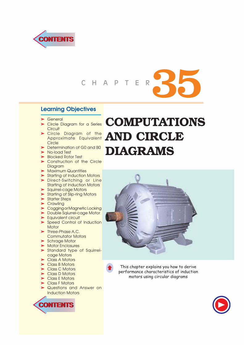
35.2. Circle Diagram for a Series Circuit
It will be shown that the end of the current vector for a series circuit with constant reactance and
voltage, but with a variable resistance is a circle. With reference to Fig. 35.1, it is clear that
I =2 2
( )=
+
V V
Z R X
=2 2
sin( )
× = φ+
V X V
X XR X
∵ sin φ =2 2
( )+
X
R X– Fig. 35.2
∴ I = (V /X) sin φIt is the equation of a circle in polar co-
ordinates, with diameter equal to V /X . Such a circle is drawn in Fig. 35.3, using the magnitude of the
current and power factor angle φ as polar co-ordinates of the point A . In other words, as resistance R
is varied (which means, in fact, φ is changed), the
end of the current vector lies on a circle with
diameter equal to V /X . For a lagging current, it is
usual to orientate the circle of Fig. 35.3 (a) such
that its diameter is horizontal and the voltage vector
takes a vertical position, as shown in Fig. 35.3 (b).
There is no difference between the two so far as
the magnitude and phase relationships are
concerned.
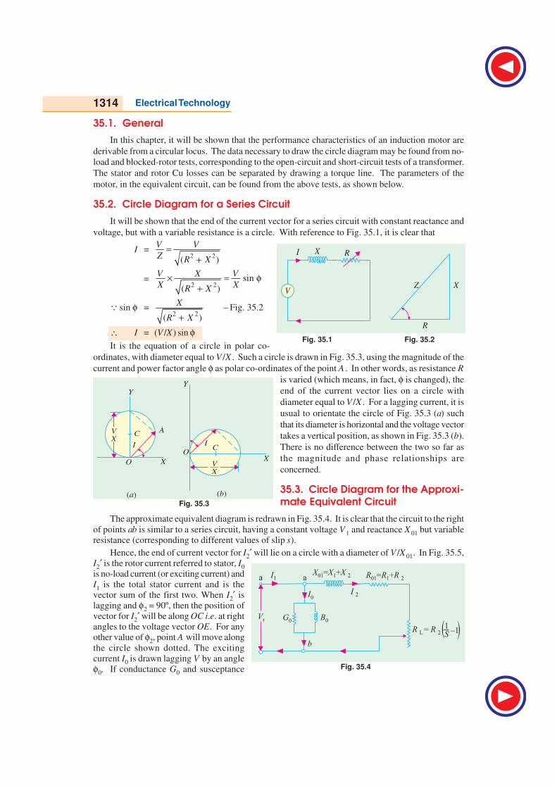
35.3. Circle Diagram for the Approxi-mate Equivalent Circuit
The approximate equivalent diagram is redrawn in Fig. 35.4. It is clear that the circuit to the right
of points ab is similar to a series circuit, having a constant voltage V 1 and reactance X 01 but variableresistance (corresponding to different values of slip s).
Hence, the end of current vector for I2′ will lie on a circle with a diameter of V /X 01. In Fig. 35.5,I2′ is the rotor current referred to stator, I0
is no-load current (or exciting current) andI1 is the total stator current and is thevector sum of the first two. When I2′ islagging and φ2 = 90º, then the position ofvector for I2′ will be along OC i.e. at rightangles to the voltage vector OE. For anyother value of φ2, point A will move along
the circle shown dotted. The excitingcurrent I0 is drawn lagging V by an angleφ0. If conductance G0 and susceptance
Fig. 35.3
f
f
V
X
V
X
Y
Y
A
O
OX
X
IC
( )a ( )b
C
I
Fig. 35.1 Fig. 35.2
I RX
VZ X
R
f
Fig. 35.4
X X X01 1 2= + R R R01 1 2= + I1
I 2I0
Vr
R R L 2=
G0 B0
a a
b
1S
_1( (
Computations and Circle Diagrams 1315
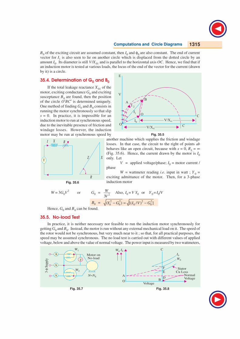
B0 of the exciting circuit are assumed constant, then I0 and φ0 are also constant. The end of current
vector for I1 is also seen to lie on another circle which is displaced from the dotted circle by an
amount I0. Its diameter is still V /X 01 and is parallel to the horizontal axis OC. Hence, we find that if
an induction motor is tested at various loads, the locus of the end of the vector for the current (drawn
by it) is a circle.
35.4. Determination of G0 and B0
If the total leakage reactance X 01 of the
motor, exciting conductance G0 and exciting
susceptance B0 are found, then the position
of the circle O′BC′ is determined uniquely.
One method of finding G0 and B0 consists in
running the motor synchronously so that slip
s = 0. In practice, it is impossible for an
induction motor to run at synchronous speed,
due to the inevitable presence of friction and
windage losses. However, the induction
motor may be run at synchronous speed by
another machine which supplies the friction and windage
losses. In that case, the circuit to the right of points ab
behaves like an open circuit, because with s = 0, RL = ∞(Fig. 35.6). Hence, the current drawn by the motor is I0
only. Let
V = applied voltage/phase; I0 = motor current /
phase
W = wattmeter reading i.e. input in watt ; Y 0 =
exciting admittance of the motor. Then, for a 3-phase
induction motor
W = 3G0V2
or G0 =2
3
W
VAlso, I0 = V Y0 or Y 0 = I0/V
B0 = 2 2 2 2
0 0 0 0( ) [( / ) ]− = −Y G I V G
Hence, G0 and B0 can be found.
35.5. No-load Test
In practice, it is neither necessary nor feasible to run the induction motor synchronously for
getting G0 and B0. Instead, the motor is run without any external mechanical load on it. The speed of
the rotor would not be synchronous, but very much near to it ; so that, for all practical purposes, the
speed may be assumed synchronous. The no load test is carried out with different values of applied
voltage, below and above the value of normal voltage. The power input is measured by two wattmeters,
Fig. 35.7 Fig. 35.8
Fig. 35.5
V/X01I0
I1
I 2
O
O
AB
C
C
E
V/X01
V
Fig. 35.6
I RX
VZ X
R
f
1316 Electrical Technology
I0 by an ammeter and V by a voltmeter, which are included in the circuit of Fig. 35.7. As motor is
running on light load, the p.f. would be low i.e. less than 0.5, hence total power input will be the
difference of the two wattmeter readings W1 and W 2. The readings of the total power input W 0 , I0 and
voltage V are plotted as in Fig. 35.8. If we extend the curve for W0, it cuts the vertical axis at point A .
OA represents losses due to friction and windage. If we subtract loss corresponding to OA from W0,
then we get the no-load electrical and magnetic losses in the machine, because the no-load input W 0 to
the motor consists of
(i) small stator Cu loss 3 I02 R1 (ii) stator core loss WCL = 3G0 V
2
(iii) loss due to friction and windage.
The losses (ii) and (iii) are collectively known as fixed losses, because they are independent of
load. OB represents normal voltage. Hence, losses at normal voltage can be found by drawing a
vertical line from B.
BD = loss due to friction and windage DE = stator Cu loss EF = core loss
Hence, knowing the core loss WCL, G0 and B0 can be found, as discussed in Art. 35.4.
Additionally, φ0 can also be found from the relation W 0 = 3 V L I0 cos φ0
∴ cos φ0 = 0
03 L
W
V Iwhere V L = line voltage and W0 is no-load stator input.
Example 35.1. In a no-load test, an induction motor took 10 A and 450 watts with a line voltage
of 110 V. If stator resistance/phase is 0.05 Ω and friction and windage losses amount to 135 watts,
calculate the exciting conductance and susceptance/phase.
Solution. stator Cu loss = 3 I02 R1 = 3 × 10
2 × 0.05 = 15 W
∴ stator core loss = 450 − 135 − 15 = 300 W
Voltage/phase V = 110/ 3 V ; Core loss = 3 G0 V2
300 = 3 G0 × (110/ 3 )2 ; G0 =
2
300
3 (110 / 3)×= 0.025 siemens/phase
Y0 = I0 / V = (10 × 3 )/110 = 0.158 siemens/
phase
B0 =2 2 2 2
0 0( ) (0.158 0.025 )− = −Y G
= 0.156 siemens/phase.
35.6. Blocked Rotor Test
It is also known as locked-rotor or short-circuit test. This test
is used to find–
1. short-circuit current with normal voltage applied to sta-
tor
2. power factor on short-circuit
Both the values are used in the construction of circle dia-
gram
3. total leakage reactance X 01 of the motor as referred to pri-
mary (i.e. stator)
4. total resistance of the motor R01 as referred to primary.
In this test, the rotor is locked (or allowed very slow rotation)
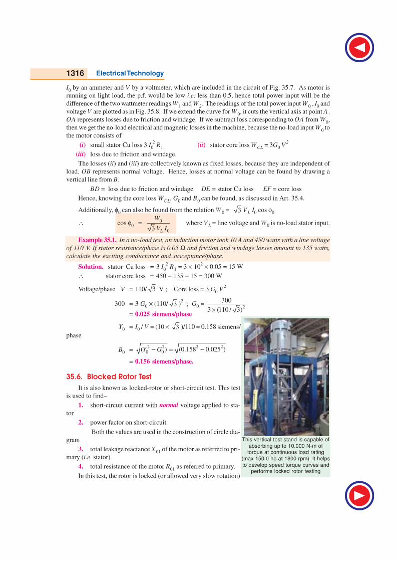
This vertical test stand is capable of
absorbing up to 10,000 N-m oftorque at continuous load rating
(max 150.0 hp at 1800 rpm). It helps
to develop speed torque curves andperforms locked rotor testing
Computations and Circle Diagrams 1317
and the rotor windings are short-circuited at slip-rings, if the motor has a wound rotor. Just as in the
case of a short-circuit test on a transformer, a reduced voltage (up to 15 or 20 per cent of normal
value) is applied to the stator terminals and is so adjusted that full-load current flows in the stator. As
in this case s = 1, the equivalent circuit of the motor is exactly like a transformer, having a short-
circuited secondary. The values of current, voltage and power input on short-circuit are measured by
the ammeter, voltmeter and wattmeter connected in the circuits as before. Curves connecting the
above quantities may also be drawn by taking two or three additional sets of readings at progressively
reduced voltages of the stator.
(a) It is found that relation between the short-circuit current and voltage is approximately a
straight line. Hence, if V is normal stator voltage, V s the short-circuit voltage (a fraction of V ), then
short-circuit or standstill rotor current, if normal voltage were applied to stator, is found from the
relation
ISN = Is × V /V s
where ISN = short-circuit current obtainable with normal voltage
Is = short-circuit current with voltage V S
(b) Power factor on short-circuit is found from
WS = 3 V SL ISL cos φS ; ∴ cos φS = WS / ( 3 V SL ISL )
where WS = total power input on short-circuit
VSL = line voltage on short-circuit
ISL = line current on short-circuit.
(c) Now, the motor input on short-circuit consists of
(i) mainly stator and rotor Cu losses
(ii) core-loss, which is small due to the fact that applied voltage is only a small percentage of the
normal voltage. This core-loss (if found appreciable) can be calculated from the curves of
Fig. 35.8.
∴ Total Cu loss = WS − WCL
3 Is
2 R01 = W s − W CL : R01 = (W s − W CL) / 3 Is
2
(d) With reference to the approximate equivalent circuit of an induction motor (Fig. 35.4), motor
leakage reactance per phase X 01 as referred to the stator may be calculated as follows :
Z01 = V S / IS X01 = 2 2
01 01( )−Z R
Usually, X 1 is assumed equal to X 2′ where X 1 and X 2 are stator and rotor reactances per phase
respectively as referred to stator. X 1 = X 2′ = X 01 / 2
If the motor has a wound rotor, then stator and rotor resistances are separated by dividing R01 in
the ratio of the d.c. resistances of stator and rotor windings.
In the case of squirrel-cage rotor, R1 is determined as usual and after allowing for ‘skin effect’ is
subtracted from R01 to give R2′ − the effective rotor resistance as referred to stator.
∴ R2′ = R01 − R1
Example 35.2. A 110-V, 3-φ, star-connected induction motor takes 25 A at a line voltage of 30
V with rotor locked. With this line voltage, power input to motor is 440 W and core loss is 40 W. The
d.c. resistance between a pair of stator terminals is 0.1 Ω. If the ratio of a.c. to d.c. resistance is 1.6,
find the equivalent leakage reactance/phase of the motor and the stator and rotor resistance per
phase. (Electrical Technology, Madras Univ. 1987)
Solution. S.C. voltage/phase, Vs = 30 / 3 = 17.3 V : Is = 25 A per phase
Z01 = 17.3/25 = 0.7 Ω (approx.) per phase
1318 Electrical Technology
Stator and rotor Cu losses = input − core loss = 440 − 40 = 400 W
∴ 3 × 252 × R01 = 400 ∴ R01 = 400/3 × 625 = 0.21 ΩΩΩΩΩ
where R01 is equivalent resistance/phase of motor as referred to stator.
Leakage reactance/phase X01 = 2 2(0.7 0.21 )− = 0.668 Ω
d.c. resistance/phase of stator = 0.1/2 = 0.05 Ωa.c. resistance/phase R1 = 0.05 × 1.6 = 0.08 Ω
Hence, effective resistance/phase of rotor as referred to stator
R2′ = 0.21 − 0.08 = 0.13 ΩΩΩΩΩ
35.7. Construction of the Circle Diagram
Circle diagram of an induction motor can be drawn by
using the data obtained from (1) no-load (2) short-circuit
test and (3) stator resistance test, as shown below.
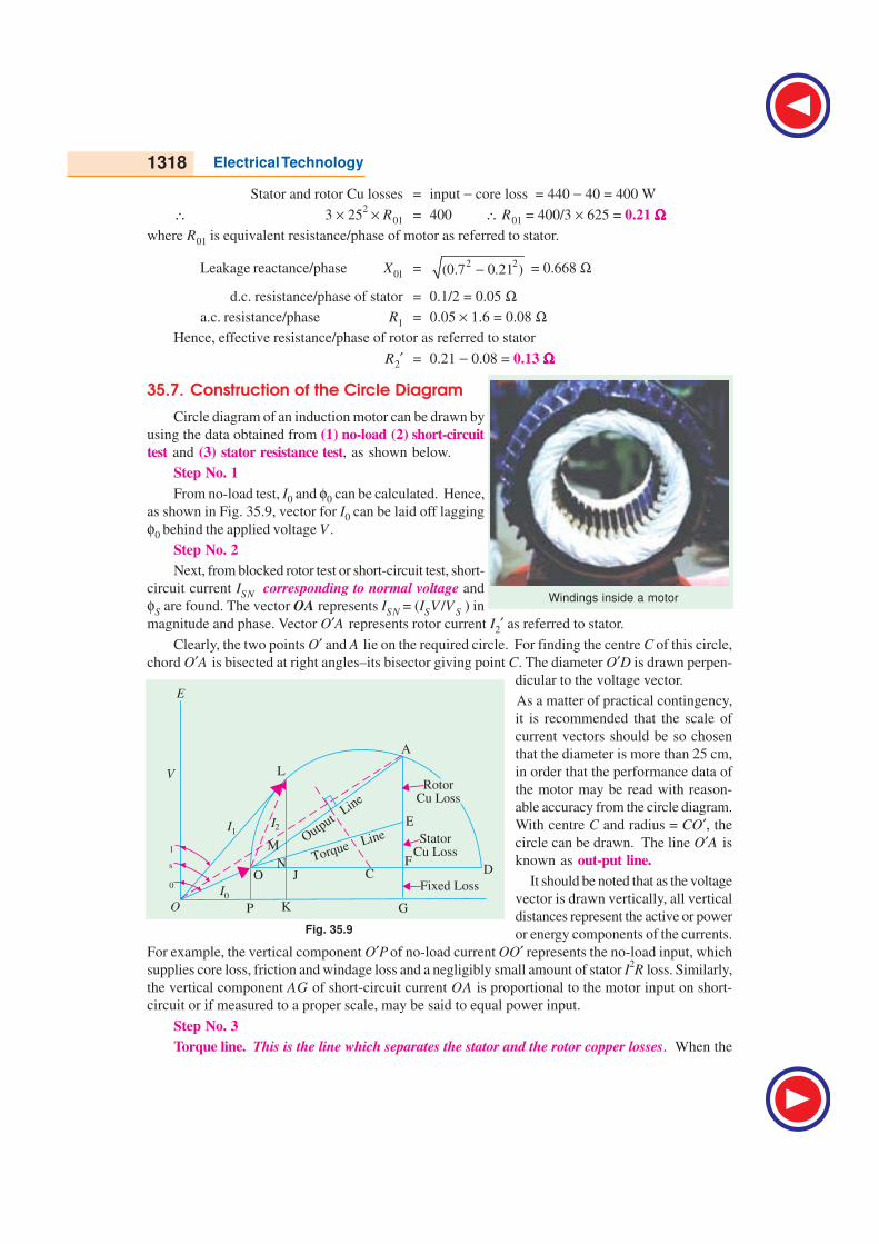
Step No. 1
From no-load test, I0 and φ0 can be calculated. Hence,
as shown in Fig. 35.9, vector for I0 can be laid off lagging
φ0 behind the applied voltage V .
Step No. 2
Next, from blocked rotor test or short-circuit test, short-
circuit current ISN corresponding to normal voltage and
φS are found. The vector OA represents ISN = (ISV /V S ) in
magnitude and phase. Vector O′A represents rotor current I2′ as referred to stator.
Clearly, the two points O′ and A lie on the required circle. For finding the centre C of this circle,
chord O′A is bisected at right angles–its bisector giving point C. The diameter O′D is drawn perpen-
dicular to the voltage vector.
As a matter of practical contingency,
it is recommended that the scale of
current vectors should be so chosen
that the diameter is more than 25 cm,
in order that the performance data of
the motor may be read with reason-
able accuracy from the circle diagram.
With centre C and radius = CO′, the
circle can be drawn. The line O′A is
known as out-put line.
It should be noted that as the voltage
vector is drawn vertically, all vertical
distances represent the active or power
or energy components of the currents.
For example, the vertical component O′P of no-load current OO′ represents the no-load input, which
supplies core loss, friction and windage loss and a negligibly small amount of stator I2R loss. Similarly,
the vertical component AG of short-circuit current OA is proportional to the motor input on short-
circuit or if measured to a proper scale, may be said to equal power input.
Step No. 3
Torque line. This is the line which separates the stator and the rotor copper losses. When the
Windings inside a motor
Fig. 35.9
F 1
F s
F 0I0
I1I ¢2
V L
G
E
A
OutputLine
Torque Line StatorCu Loss
C
P KO
DJO ¢Fixed Loss
RotorCu Loss
M
N F
E

Computations and Circle Diagrams 1319
rotor is locked, then all the power supplied to the motor goes to meet core losses and Cu losses in the
stator and rotor windings. The power input is proportional to AG. Out of this, FG (= O′P) represents
fixed losses i.e. stator core loss and friction and windage losses. AF is proportional to the sum of the
stator and rotor Cu losses. The point E is such that
AE
EF=
rotor Cu loss
stator Cu loss
As said earlier, line O′E is known as torque line.
How to locate point E ?
(i) Squirrel-cage Rotor. Stator resistance/phase i.e. R1 is found from stator-resistance test.
Now, the short-circuit motor input W s is approximately equal to motor Cu losses (neglecting iron
losses).
Stator Cu loss = 3IS
2 R1 ∴ rotor Cu loss = W S − 3 IS
2 R1 ∴ AE
EF =
2
1
2
1
3
3
−S S
S
W I R
I R
(ii) Wound Rotor. In this case, rotor and stator resistances per phase r2 and r1 can be easily
computed. For any values of stator and rotor currents I1 and I2 respectively, we can write
AE
EF=
222 2 2 22
1 11 1
=
I r r I
r II r; Now, 1
2
I
I = K = transformation ratio
AE
EF=
2
2 2 22
1 1 1
/ equivalent rotor resistance per phase1
stator resistance per phase
′× = = =
r r K r
r r rK
Value of K may be found from short-circuit test itself by using two ammeters, both in stator and
rotor circuits.
Let us assume that the motor is running and taking a current OL (Fig. 35.9). Then, the perpendicular
JK represents fixed losses, JN is stator Cu loss, NL is the rotor input, NM is rotor Cu loss, ML is rotor
output and LK is the total motor input.
From our knowledge of the relations between the above-given various quantities, we can write :
3 . VL . LK = motor input 3 . V L . JK = fixed losses
3 . V L . JN = stator copper loss 3 . VL . MN = rotor copper loss
3 . VL . MK = total loss 3 . V L . ML = mechanical output
3 . VL. NL = rotor input ∝ torque
1. ML / LK = output/input = efficiency
2. MN / NL = (rotor Cu loss)/(rotor input) = slip, s.
3. ML
NL=
rotor output
rotor input = 1 − s =
S
N
N =
actual speed
synchronous speed
4.LK
OL= power factor
Hence, it is seen that, at least, theoretically, it is possible to obtain all the characteristics of an
induction motor from its circle diagram. As said earlier, for drawing the circle diagram, we need (a)
stator-resistance test for separating stator and rotor Cu losses and (b) the data obtained from (i) no-
load test and (ii) short-circuit test.
35.8. Maximum Quantities
It will now be shown from the circle diagram (Fig. 35.10) that the maximum values occur at the
positions stated below :
(i) Maximum Output
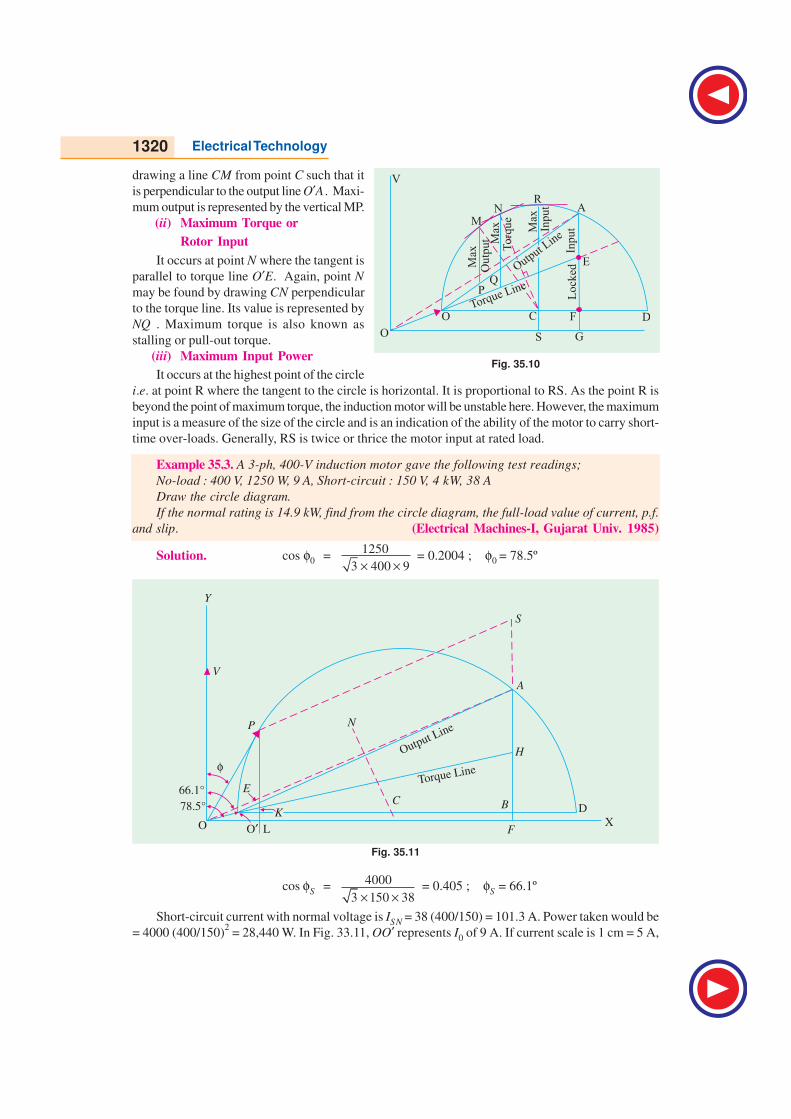
It occurs at point M where the tangent is parallel to output line O′A . Point M may be located by
1320 Electrical Technology
drawing a line CM from point C such that it
is perpendicular to the output line O′A . Maxi-
mum output is represented by the vertical MP.
(ii) Maximum Torque or
Rotor Input
It occurs at point N where the tangent is
parallel to torque line O′E. Again, point N
may be found by drawing CN perpendicular
to the torque line. Its value is represented by
NQ . Maximum torque is also known as
stalling or pull-out torque.
(iii) Maximum Input Power
It occurs at the highest point of the circle
i.e. at point R where the tangent to the circle is horizontal. It is proportional to RS. As the point R is
beyond the point of maximum torque, the induction motor will be unstable here. However, the maximum
input is a measure of the size of the circle and is an indication of the ability of the motor to carry short-
time over-loads. Generally, RS is twice or thrice the motor input at rated load.
Example 35.3. A 3-ph, 400-V induction motor gave the following test readings;
No-load : 400 V, 1250 W, 9 A, Short-circuit : 150 V, 4 kW, 38 A
Draw the circle diagram.
If the normal rating is 14.9 kW, find from the circle diagram, the full-load value of current, p.f.
and slip. (Electrical Machines-I, Gujarat Univ. 1985)
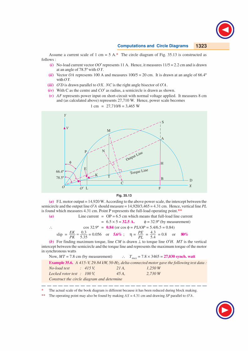
Solution. cos φ0 =1250
3 400 9× × = 0.2004 ; φ0 = 78.5º
Fig. 35.11
cos φS =4000
3 150 38× × = 0.405 ; φS = 66.1º
Short-circuit current with normal voltage is ISN = 38 (400/150) = 101.3 A. Power taken would be
= 4000 (400/150)2 = 28,440 W. In Fig. 33.11, OO′ represents I0 of 9 A. If current scale is 1 cm = 5 A,
Fig. 35.10
MN
R
E
Max
Max
Max
To
rqu
e
Ou
tpu
t
Inp
ut
Output Lin
e
Torque LinePQ
Lo
cked
Inp
ut
O O S G
C F D
V
A

Computations and Circle Diagrams 1321
then vector OO′ = 9/5 = 1.8 cm* and is drawn at an angle of φ0 = 78.5º with the vertical OV (which
represents voltage). Similarly, OA represents ISN (S.C. current with normal voltage applied) equal to
101.3 A. It measures 101.3/5 = 20.26* cm and is drawn at an angle of 66.1º, with the vertical OV.
Line O′D is drawn parallel to OX. NC is the right-angle bisector of O′A . The semi-circle Ο ′AD
is drawn with C as the centre. This semi-circle is the locus of the current vector for all load conditions
from no-load to short-circuit. Now, AF represents 28,440 W and measures 8.1 cm. Hence, power
scale becomes : 1 cm = 28,440/8.1 = 3,510 W. Now, full-load motor output = 14.9 × 103 = 14,900 W.
According to the above calculated power scale, the intercept between the semi-circle and output line
O′A should measure = 14,900/3510 = 4.25 cm. For locating full-load point P, B A is extended. A S is
made equal to 4.25 cm and SP is drawn parallel to output line O′A . PL is perpendicular to OX.
Line current = OP = 6 cm = 6 × 5 = 30 A; φ = 30º (by measurement)
p.f. = cos 30º = 0.886 (or cos φ = PL/OP = 5.2/6 = 0.865)
Now, slip =rotor Cu loss
rotor input
In Fig. 35.11, EK represents rotor Cu loss and PK represents rotor input.
∴ slip =0.3
4.5=EK
PK = 0.067 or 6.7%
Example 35.4. Draw the circle diagram for a 3.73 kW, 200-V, 50-Hz, 4-pole, 3-φ star-connected
induction motor from the following test data :
No-load : Line voltage 200 V, line current 5 A; total input 350 W
Blocked rotor : Line voltage 100 V, line current 26 A; total input 1700 W
Estimate from the diagram for full-load condition, the line current, power factor and also the
maximum torque in terms of the full-load torque. The rotor Cu loss at standstill is half the total Cu
loss. (Electrical Engineering, Bombay Univ. 1987)
78º15¢
67º42¢
Output Line
Torque Line
T
CHA
F
G
SO
V
R
B
X
X ¢
D
M
ESta
tor
Cu
Roto
rC
u
Max
.T
orq
ue
K
N
P
Loss
Loss
Fig. 35.12
Solution. No-load test
I0 = 5 A, cos φ0 = 350
3 200 5× × = 0.202 ; φ0 = 78º15′
* The actual lengths are different from these values, due to reduction in block making.

1322 Electrical Technology
Blocked-rotor test :
cos φs =1700
3 100 26× × = 0.378 ; φs= 67º42′
Short-circuit current with normal voltage, ISN = 26 × 200/100 = 52 A
Short-circuit/blocked rotor input with normal voltage = 1700(52/26)2 = 6,800 W
In the circle diagram of Fig. 35.12, voltage is represented along OV which is drawn perpendicular
to OX. Current scale is 1 cm = 2 A
Line OA is drawn at an angle of φ0 = 78º15′ with OV and 2.5 cm in length. Line A X′ is drawn
parallel to OX. Line OB represents short-circuit current with normal voltage i.e. 52 A and measures
52/2 = 26 cm. A B represents output line. Perpendicular bisector of A B is drawn to locate the centre
C of the circle. With C as centre and radius = CA, a circle is drawn which passes through points A and
B. From point B, a perpendicular is drawn to the base. BD represents total input of 6,800 W for
blocked rotor test. Out of this, ED represents no-load loss of 350 W and BE represents 6,800 − 350 =
6,450 W. Now BD = 9.8 cm and represents 6,800 W
∴ power scale = 6,800/9.8 = 700 watt/cm or 1 cm = 700 W
BE which represents total copper loss in rotor and stator, is bisected at point T to separate the two
losses. AT represents torque line.
Now, motor output = 3,730 watt. It will be represented by a line = 3,730/700 = 5.33 cm
The output point P on the circle is located thus :
DB is extended and BR is cut = 5.33 cm. Line RP is drawn parallel to output line AB and cuts the
circle at point P. Perpendicular PS is drawn and P is joined to origin O.
Point M corresponding to maximum torque is obtained thus :
From centre C, a line CM is drawn such that it is perpendicular to torque line AT. It cuts the circle
at M which is the required point. Point M could also have been located by drawing a line parallel to
the torque line. MK is drawn vertical and it represents maximum torque.
Now, in the circle diagram, OP = line current on full-load = 7.6 cm. Hence, OP represents 7.6 ×2 = 15.2 A
Power factor on full-load =6.45
7.6=SP
OP = 0.86
Max. torque
F.L. torque=
10
5.6=MK
PG = 1.8
∴ Max. torque = 180% of full-load torque.
Example. 35.5. Draw the circle diagram from no-load and short-circuit test of a 3-phase. 14.92
k W, 400-V, 6-pole induction motor from the following test results (line values).
No-load : 400-V, 11 A, p.f. = 0.2
Short-circuit : 100-V, 25 A, p.f. = 0.4
Rotor Cu loss at standstill is half the total Cu loss.
From the diagram, find (a) line current, slip, efficiency and p.f. at full-load (b) the maximum
torque. (Electrical Machines-I, Gujarat Univ. 1985)
Solution. No-load p.f. = 0.2; φ0 = cos− 1
(0.2) = 78.5º
Short-circuit p.f. = 0.4: φs = cos− 1
(0.4) = 66.4º
S.C. current ISN if normal voltage were applied = 25 (400/100) = 100 A
S.C. power input with this current = 3 × 400 × 100 × 0.4 = 27,710 W
Computations and Circle Diagrams 1323
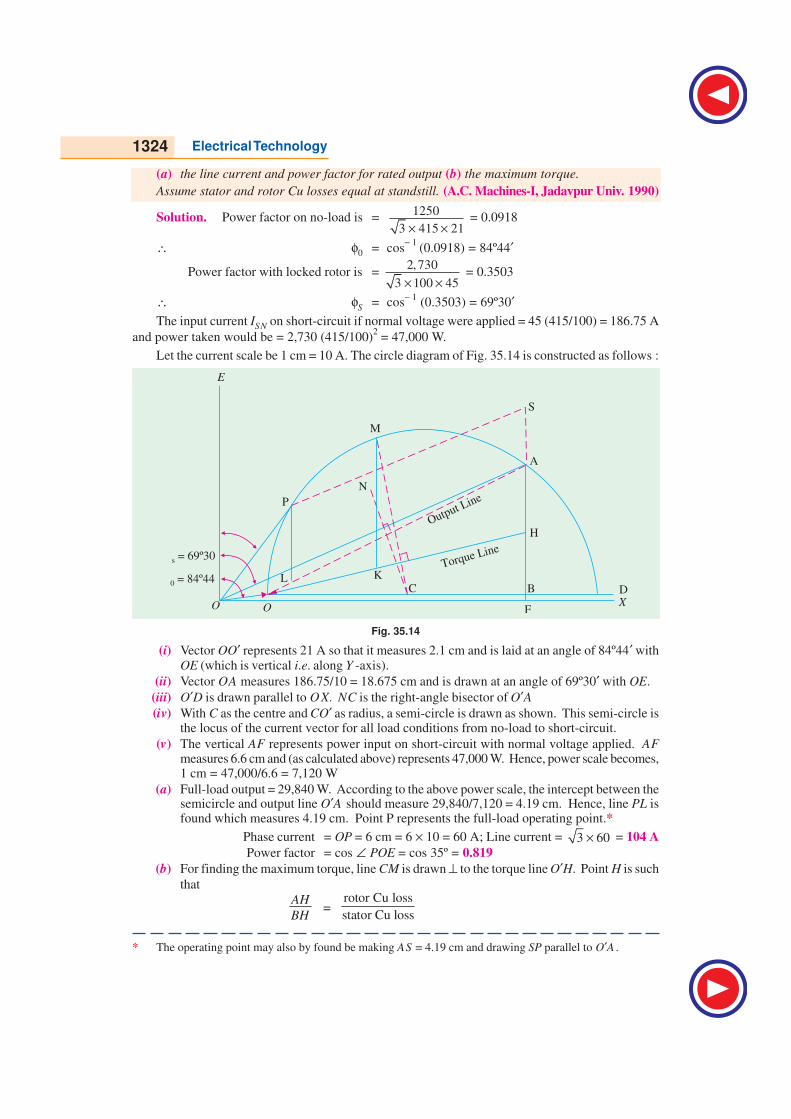
Assume a current scale of 1 cm = 5 A.* The circle diagram of Fig. 35.13 is constructed as
follows :
(i) No-load current vector OO′ represents 11 A. Hence, it measures 11/5 = 2.2 cm and is drawnat an angle of 78.5º with O Y.
(ii) Vector OA represents 100 A and measures 100/5 = 20 cm. It is drawn at an angle of 66.4ºwith OY.
(iii) O′D is drawn parallel to OX. NC is the right angle bisector of O′A .
(iv) With C as the centre and CO′ as radius, a semicircle is drawn as shown.
(v) AF represents power input on short-circuit with normal voltage applied. It measures 8 cmand (as calculated above) represents 27,710 W. Hence, power scale becomes
1 cm = 27,710/8 = 3,465 W
Fig. 35.13
(a) F.L motor output = 14,920 W. According to the above power scale, the intercept between thesemicircle and the output line O′A should measure = 14,920/3,465 = 4.31 cm. Hence, vertical line PLis found which measures 4.31 cm. Point P represents the full-load operating point.**
(a) Line current = OP = 6.5 cm which means that full-load line current
= 6.5 × 5 = 32.5 A. φ = 32.9º (by measurement)
∴ cos 32.9º = 0.84 (or cos φ = PL/OP = 5.4/6.5 = 0.84)
slip = 0.3
5.35=EK
PK= 0.056 or 5.6% ; η =
PE
PL =
4.3
5.4 = 0.8 or 80%
(b) For finding maximum torque, line CM is drawn ⊥ to torque line O′H. MT is the vertical
intercept between the semicircle and the torque line and represents the maximum torque of the motorin synchronous watts
Now, MT = 7.8 cm (by measurement) ∴ Tmax = 7.8 × 3465 = 27,030 synch. watt
Example 35.6. A 415-V, 29.84 kW, 50-Hz, delta-connected motor gave the following test data :
No-load test : 415 V, 21 A, 1,250 W
Locked rotor test : 100 V, 45 A, 2,730 W
Construct the circle diagram and determine
* The actual scale of the book diagram is different because it has been reduced during block making.
** The operating point may also be found by making AS = 4.31 cm and drawing SP parallel to O′A .
1324 Electrical Technology
(a) the line current and power factor for rated output (b) the maximum torque.
Assume stator and rotor Cu losses equal at standstill. (A.C. Machines-I, Jadavpur Univ. 1990)
Solution. Power factor on no-load is =1250
3 415 21× × = 0.0918
∴ φ0 = cos− 1
(0.0918) = 84º44′
Power factor with locked rotor is = 2,730
3 100 45× × = 0.3503
∴ φS = cos− 1
(0.3503) = 69º30′The input current ISN on short-circuit if normal voltage were applied = 45 (415/100) = 186.75 A
and power taken would be = 2,730 (415/100)2 = 47,000 W.
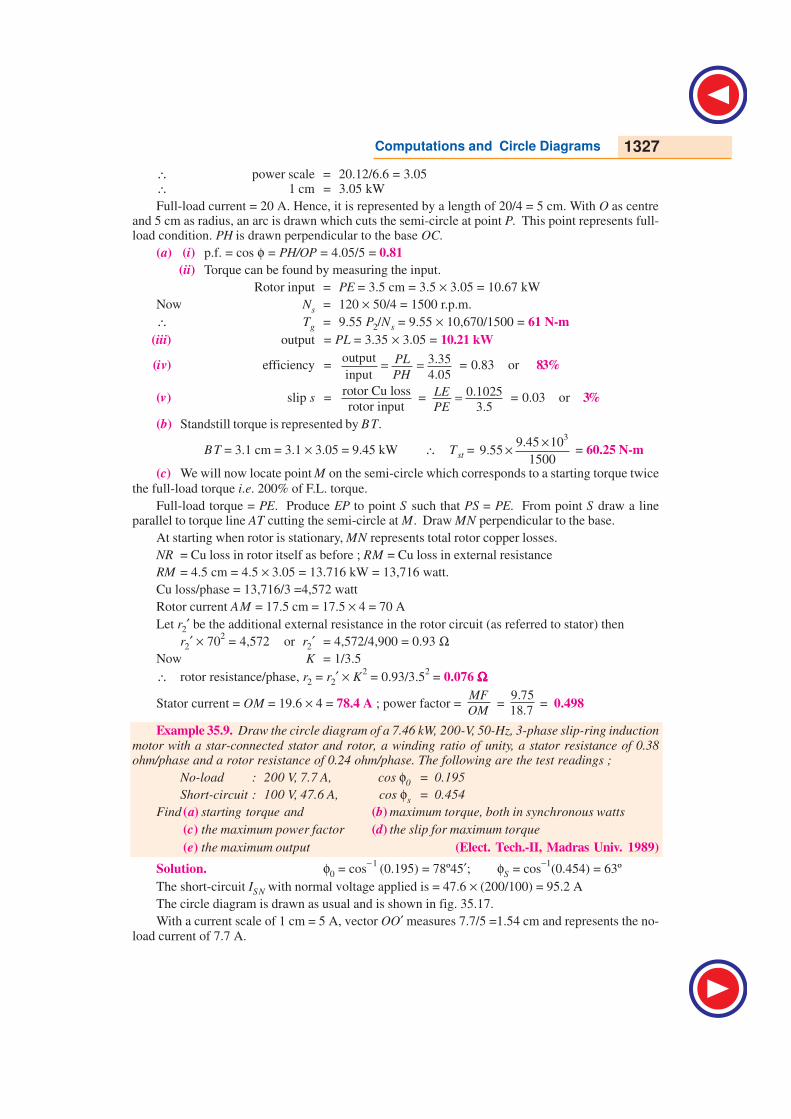
Let the current scale be 1 cm = 10 A. The circle diagram of Fig. 35.14 is constructed as follows :
f ¢0 = 84º44
f ¢s = 69º30
O ¢
Output Line
Torque Line
H
C
P
L
O
S
A
X
D
F
M
BK
N
f
E
Fig. 35.14
(i) Vector OO′ represents 21 A so that it measures 2.1 cm and is laid at an angle of 84º44′ withOE (which is vertical i.e. along Y -axis).
(ii) Vector OA measures 186.75/10 = 18.675 cm and is drawn at an angle of 69º30′ with OE.
(iii) O′D is drawn parallel to OX. NC is the right-angle bisector of O′A(iv) With C as the centre and CO′ as radius, a semi-circle is drawn as shown. This semi-circle is
the locus of the current vector for all load conditions from no-load to short-circuit.
(v) The vertical AF represents power input on short-circuit with normal voltage applied. AFmeasures 6.6 cm and (as calculated above) represents 47,000 W. Hence, power scale becomes,1 cm = 47,000/6.6 = 7,120 W
(a) Full-load output = 29,840 W. According to the above power scale, the intercept between thesemicircle and output line O′A should measure 29,840/7,120 = 4.19 cm. Hence, line PL isfound which measures 4.19 cm. Point P represents the full-load operating point.*
Phase current = OP = 6 cm = 6 × 10 = 60 A; Line current = 3 60× = 104 A
Power factor = cos ∠ POE = cos 35º = 0.819
(b) For finding the maximum torque, line CM is drawn ⊥ to the torque line O′H. Point H is such
that
AH
BH=
rotor Cu loss
stator Cu loss
* The operating point may also by found be making AS = 4.19 cm and drawing SP parallel to O′A .

Computations and Circle Diagrams 1325
Since the two Cu losses are equal, point H is the mid-point of A B.
Line MK represents the maximum torque of the motor in synchronous watts
MK = 7.3 cm (by measurement) = 7.3 × 7,120 = 51,980 synch. watt.
Example 35.7. Draw the circle diagram for a 5.6 kW, 400-V, 3-φ, 4-pole, 50-Hz, slip-ringinduction motor from the following data :
No-load readings : 400 V, 6 A, cos φ0 = 0.087 : Short-circuit test : 100 V, 12 A, 720 W.
The ratio of primary to secondary turns = 2.62, stator resistance per phase is 0.67 Ω and of therotor is 0.185 Ω. Calculate
(i) full-load current (ii) full-load slip
(iii) full-load power factor
(iv) maximum torque
full - load torque(v) maximum power.
Solution. No-load condition
φ0 = cos−1
(0.087) = 85º
85º
69º40¢
Output Line
Torque Line
T
CA
F
G
SO
R
B
X
X¢
D
M
E
K
N
L
Y
P
Fig. 35.15
Short-circuit condition
Short-circuit current with normal voltage = 12 × 400/100 = 48 A
Total input = 720 × (48/12)2 = 11.52 kW
cos φs =720
3 100 12× × = 0.347 or φs = 69º 40′
Current scale is, 1 cm = 2 A
In the circle diagram of Fig. 35.15, OA = 3 cm and inclined at 85º with OV. Line OB representsshort-circuit current with normal voltage. It measures 48/2 = 24 cm and represent 48 A. BD isperpendicular to OX.
For Drawing Torque Line
K = 2.62 R1 = 0.67 Ω R2 = 0.185 Ω(in practice, an allowance of 10% is made for skin effect)
∴ rotor Cu loss
stator Cu loss= 2.62
2 ×
0.185
0.67 = 1.9 ∴ rotor Cu loss 1.9
total Cu loss 2.9= = 0.655
Now BD = 8.25 cm and represents 11.52 kW
power scale = 11.52/8.25 = 1.4 kW/cm

1326 Electrical Technology
∴ 1 cm = 1.4 kW
BE represents total Cu loss and is divided at point T in the ratio 1.9 : 1.
BT = BE × 1.9/2.9 = 0.655 × 8 = 5.24 cm
AT is the torque lineFull-load output = 5.6 kW
It is represented by a line = 5.6/1.4 =4 cmDB is produced to R such that BR = 4 cm. Line RP is parallel to output line and cuts the circle at
P. OP represents full-load current.PS is drawn vertically. Points M and Y represent points of maximum torque and maximum output
respectively.
(i) F.L. current = OP = 5.75 cm = 5.75 × 2 = 11.5 A
(ii) F.L. slip = 0.2
4.25=FG
PG = 0.047 or 4.7%
(iii) p.f. =SP
OP = 4.6
5.75 = 0.8
(iv)max. torque
full-load torque= MK
PG =
10.05
4.25 = 2.37
(v) Maximum output is represented by Y L = 7.75 cm.
∴ Max. output = 7.75 × 1.4 = 10.8 kW
Example 35.8. A 440-V, 3-φ, 4-pole, 50-Hz slip-ring motor gave the following test results :No-load reading : 440 V, 9 A, p.f. = 0.2Blocked rotor test : 110 V, 22 A, p.f. = 0.3
The ratio of stator to rotor turns per phase is 3.5/1. The stator and rotor Cu losses are dividedequally in the blocked rotor test. The full-load current is 20 A. Draw the circle diagram and obtainthe following :
(a) power factor, output power, efficiency and slip at full-load(b) standstill torque or starting torque.(c) resistance to be inserted in the rotor circuit for giving a starting torque 200 % of the
full-load torque. Also, find the current and power factor under these conditions.
Solution. No-load p.f. = 0.2 ∴ φ0 = cos− 1
(0.2) = 78.5ºShort-circuit p.f. = 0.3 ∴ φS = 72.5ºShort-circuit current at normal voltage = 22 × 440/110 = 88 A
S.C. input = 3 × 440 × 88 × 0.3 = 20,120 W = 20.12 kWTake a current scale of 1 cm = 4 A
In the circle diagram of Fig. 35.16, OA = 2.25 cm drawn at an angle of 78.5º behind OV.Similarly, OB = 88/4 = 22 cm and is drawn at an angle of 72.50 behind OV. The semi-circle is drawnas usual. Point T is such that BT = TD. Hence, torque line AT can be drawn. BC represents 20.12 kW.By measurement BC = 6.6 cm.
Output
Line
Line
Torque
T
A E
O
M
B
C
D
P
H
L
SR
N
F
V
Fig. 35.16
Computations and Circle Diagrams 1327
∴ power scale = 20.12/6.6 = 3.05∴ 1 cm = 3.05 kW
Full-load current = 20 A. Hence, it is represented by a length of 20/4 = 5 cm. With O as centreand 5 cm as radius, an arc is drawn which cuts the semi-circle at point P. This point represents full-load condition. PH is drawn perpendicular to the base OC.
(a) (i) p.f. = cos φ = PH/OP = 4.05/5 = 0.81
(ii) Torque can be found by measuring the input.
Rotor input = PE = 3.5 cm = 3.5 × 3.05 = 10.67 kW
Now Ns = 120 × 50/4 = 1500 r.p.m.
∴ Tg = 9.55 P2/Ns = 9.55 × 10,670/1500 = 61 N-m
(iii) output = PL = 3.35 × 3.05 = 10.21 kW
(iv) efficiency =output 3.35
input 4.05= =PL
PH = 0.83 or 83%
(v) slip s =rotor Cu loss
rotor input =
0.1025
3.5
LE
PE= = 0.03 or 3%
(b) Standstill torque is represented by BT.
BT = 3.1 cm = 3.1 × 3.05 = 9.45 kW ∴ Tst = 3
9.45 109.55
1500
×× = 60.25 N-m
(c) We will now locate point M on the semi-circle which corresponds to a starting torque twice
the full-load torque i.e. 200% of F.L. torque.
Full-load torque = PE. Produce EP to point S such that PS = PE. From point S draw a lineparallel to torque line AT cutting the semi-circle at M. Draw MN perpendicular to the base.
At starting when rotor is stationary, MN represents total rotor copper losses.
NR = Cu loss in rotor itself as before ; RM = Cu loss in external resistance
RM = 4.5 cm = 4.5 × 3.05 = 13.716 kW = 13,716 watt.
Cu loss/phase = 13,716/3 =4,572 watt
Rotor current AM = 17.5 cm = 17.5 × 4 = 70 A
Let r2′ be the additional external resistance in the rotor circuit (as referred to stator) then
r2′ × 702 = 4,572 or r2′ = 4,572/4,900 = 0.93 Ω
Now K = 1/3.5
∴ rotor resistance/phase, r2 = r2′ × K2 = 0.93/3.5
2 = 0.076 ΩΩΩΩΩ
Stator current = OM = 19.6 × 4 = 78.4 A ; power factor = MF
OM =
9.75
18.7 = 0.498
Example 35.9. Draw the circle diagram of a 7.46 kW, 200-V, 50-Hz, 3-phase slip-ring induction
motor with a star-connected stator and rotor, a winding ratio of unity, a stator resistance of 0.38ohm/phase and a rotor resistance of 0.24 ohm/phase. The following are the test readings ;
No-load : 200 V, 7.7 A, cos φ0 = 0.195
Short-circuit : 100 V, 47.6 A, cos φs = 0.454
Find (a) starting torque and (b) maximum torque, both in synchronous watts
(c) the maximum power factor (d) the slip for maximum torque
(e) the maximum output (Elect. Tech.-II, Madras Univ. 1989)
Solution. φ0 = cos−1
(0.195) = 78º45′; φS = cos−1
(0.454) = 63º
The short-circuit ISN with normal voltage applied is = 47.6 × (200/100) = 95.2 A
The circle diagram is drawn as usual and is shown in fig. 35.17.
With a current scale of 1 cm = 5 A, vector OO′ measures 7.7/5 =1.54 cm and represents the no-load current of 7.7 A.

1328 Electrical Technology
Similarly, vector OA represents ISN i.e. short-circuit current with normal voltage and measures
95.2/5 = 19.04 cm
Both vectors are drawn at their respective angles with OE.
The vertical line AF measures the power input on short-circuit with normal voltage and is= 3 × 200 × 95.2 × 0.454 = 14,970 W.
Since AF measures 8.6 cm, the power scale is 1 cm = 14,970/8.6 = 1740 W
The point H is such that
63º
78º45
Output Line
Torque Line
CO 0
A
X
G
F
M
B
N
K
D
L
PH
E
Fig. 35.17
AH
AB= rotor Cu loss rotor resistance 0.24
total Cu loss rotor + stator resistance 0.62= =*
Now AB = 8.2 cm (by measurement) ∴ AH = 8.2 × 0.24/0.62 = 3.2 cm
(a) Starting torque = AH = 3.2 cm = 3.2 × 1740 = 5,570 synch. watt.
(b) Line CM is drawn perpendicular to the torque line O′H. The intercept MN represents themaximum torque in synchronous watts.
Maximum torque = MN = 7.15 cm = 7.15 × 1740 = 12,440 synch. watts.
(c) For finding the maximum power, line OP is drawn tangential to the semi-circle.
∠ POE = 28.5º∴ maximum p.f. = cos 28.5º = 0.879
(d) The slip for maximum torque is = KN/MN= 1.4/7.15 = 0.195
(e) Line CL is drawn perpendicular to the output line O′A . From L is drawn the vertical line LD.It measures 5.9 cm and represents the maximum output.
∴ maximum output = 5.9 × 1740 = 10,270 W
Tutorial Problems 35.1
1. A 300 h.p. (223.8 kW), 3000-V, 3-φ, induction motor has a magnetising current of 20 A at 0.10 p.f.
and a short-circuit (or locked) current of 240 A at 0.25 p.f. Draw the circuit diagram, determine the
p.f. at full-load and the maximum horse-power. [0.85 p.f. 621 h.p. (463.27 kW)] (I.E.E. London)
2. The following are test results for a 18.65 kW, 3-φ, 440.V slip-ring induction motor :
Light load : 440-V, 7.5 A, 1350 W (including 650 W friction loss).
* Because K = 1, otherwise it should be R2′ = R
2/K
2.
Computations and Circle Diagrams 1329
S.C. test : 100 V, 32 A, 1800 W
Draw the locus diagram of the stator current and hence obtain the current, p.f. and slip on full-load.On short-circuit, the rotor and stator copper losses are equal. [30 A, 0.915, 0.035] (London Univ)
3. Draw the circle diagram for 20 h.p. (14.92 kW), 440-V, 50-Hz, 3-φ induction motor from the followingtest figures (line values) :
No-load : 440 V, 10A, p.f. 0.2 Short-circuit : 200 V, 50 A, p.f. 0.4
From the diagram, estimate (a) the line current and p.f. at full-load (b) the maximum power developed(c) the starting torque. Assume the rotor and stator I
2R losses on short-circuit to be equal.
[(a) 28.1 A at 0.844 p.f. (b) 27.75 kW (c) 11.6 synchronous kW/phase] (London Univ.)
4. A 40 h.p. (29.84.kW), 440-V, 50-Hz, 3-phase induction motor gave the following test results
No. load : 440 V, 16 A, p.f. = 0.15 S.C. test : 100 V, 55 A, p.f. = 0.225
Ratio of rotor to stator losses on short-circuit = 0.9. Find the full-load current and p.f., the pull-outtorque and the maximum output power developed.
[49 A at 0.88 p.f. ; 78.5 synch. kW or 2.575 times F.L. torque ; 701.2 kW] (I.E.E. London)
5. A 40 h.p. (29.84 kW), 50-Hz, 6-pole, 420-V, 3-φ, slip-ring induction motor furnished the followingtest figures :
No-load : 420 V, 18 A, p.f. = 0.15 S.C. test : 210 V, 140 A, p.f. = 0.25
The ratio of stator to rotor Cu losses on short-circuit was 7 : 6. Draw the circle diagram and findfrom it (a) the full-load current and power factor (b) the maximum torque and power developed.
[(a) 70 A at 0.885 p.f. (b) 89.7 kg.m ; 76.09 kW] (I.E.E. London)
6. A 500 h.p. (373 kW), 8-pole, 3-φ, 6,000-V, 50-Hz induction motor gives on test the followingfigures :
Running light at 6000 V, 14 A/phase, 20,000 W ; Short-circuit at 2000 V, 70 A/phase, 30,500 W
The resistance/phase of the star-connected stator winding is 1.1 Ω, ratio of transformation is 4 :1.Draw the circle diagram of this motor and calculate how much resistance must be connected in eachphase of the rotor to make it yield full-load torque at starting. [0.138 ΩΩΩΩΩ] (London Univ.)
7. A 3-phase induction motor has full-load output of 18.65 kW at 220 V, 720 r.p.m. The full-load p.f.is 0.83 and efficiency is 85%. When running light, the motor takes 5 A at 0.2 p.f. Draw the circlediagram and use it to determine the maximum torque which the motor can exert (a) in N-m (b) interms of full-load torque and (c) in terms of the starting torque.
[(a) 268.7 N-m (b) 1.08 (c) 7.2 approx.] (London Univ.)
8. A 415-V, 40 h.p. (29.84 kW), 50.Hz, ∆-connected motor gave the following test data :
No-load test : 415 V, 21 A, 1250 W ; Locked rotor test : 100 V, 45 A, 2,730 W
Construct the circle diagram and determine
(a)the line current and power factor for rated output (b) the maximum torque. Assume stator androtor Cu losses equal at standstill.
[(a) 104 A : 0.819 (b) 51,980 synch watt] (A.C. Machines-I, Jadavpur Univ. 1978)
9. Draw the no-load and short circuit diagram for a 14.92 kW., 400-V, 50-Hz, 3-phase star-connectedinduction motor from the following data (line values) :
No load test : 400 V, 9 A, cos φ = 0.2
Short circuit test : 200 V, 50 A, cos φ = 0.4
From the diagram find (a) the line current and power factor at full load, and (b) the maximum output
power. [(a) 32.0 A, 0.85 (b) 21.634 kW]
35.9. Starting of Induction Motors
It has been shown earlier that a plain induction motor is similar in action to a polyphase transformer
with a short-circuited rotating secondary. Therefore, if normal supply voltage is applied to the stationary
motor, then, as in the case of a transformer, a very large initial current is taken by the primary, at least,
for a short while. It would be remembered that exactly similar conditions exist in the case of a d.c.
motor, if it is thrown directly across the supply lines, because at the time of starting it, there is no back
e.m.f. to oppose the initial inrush of current.

1330 Electrical Technology
Induction motors, when direct-switched, take five to seven times their full-load current and develop
only 1.5 to 2.5 times their full-load torque. This initial excessive current is objectionable because it
will produce large line-voltage drop that, in turn, will affect the operation of other electrical equipment
connected to the same lines. Hence, it is not advisable to line-start motors of rating above 25 kW to
40 kW.
It was seen in Art. 34.15 that the starting torque of an induction motor can be improved by
increasing the resistance of the rotor circuit. This is easily feasible in the case of slip-ring motors but
not in the case of squirrel-cage motors. However, in their case, the initial in-rush of current is controlled
by applying a reduced voltage to the stator during the starting period, full normal voltage being
applied when the motor has run up to speed.
35.10. Direct-switching or Line starting of Induction Motors
It has been shown earlier that
Rotor input = 2 π Ns T = k T –Art. 34.36
Also, rotor Cu loss = s × rotor input
∴ 3 Ι 22R2 = s × kT ∴ T ∝ I 2
2/s (if R2 is the same)
Now I2 ∝ I1 ∴ T ∝ I12/s or T = K I1
2/s
At starting moment s = 1 ∴ Tst = K Ist
2 where Ist = starting current
If If = normal full-load current and sf = full-load slip
thenTf = K If
2 / sf ∴ st
f
T
T=
2
.stf
f
Is
I
When motor is direct-switched onto normal voltage, then starting current is the short-circuit
current Isc.
∴ st
f
T
T=
2
.scf
f
Is
I
= a2
. sf where a = Isc / If
Suppose in a case, Isc = 7 If , sf = 4% = 0.04, the Tst / T f = 72 × 0.04 = 1.96
∴ starting torque = 1.96 × full-load torque
Hence, we find that with a current as great as seven times the full-load current, the motor develops
a starting torque which is only 1.96 times the full-load value.
Some of the methods for starting induction motors are discussed below :
Squirrel-cage Motors
(a) Primary resistors (or rheostat) or reactors
(b) Auto-transformer (or autostarter)
(c) Star-delta switches
In all these methods, terminal voltage of the squirrel-cage motor is reduced during starting.
Slip-ring Motors
(a) Rotor rheostat
35.11. Squirrel-cage Motors
(a) Primary resistors
Their purpose is to drop some voltage and hence reduce the voltage applied across the motor
terminals. In this way, the initial current drawn by the motor is reduced. However, it should be noted
that whereas current varies directly as the voltage, the torque varies as square of applied voltage*
* When applied voltage is reduced, the rotating flux Φ is reduced which, in turn, decreases rotor e.m.f. and
hence rotor current I2. Starting torque, which depends both on Φ and I2 suffers on two counts when
impressed voltage is reduced.
Computations and Circle Diagrams 1331
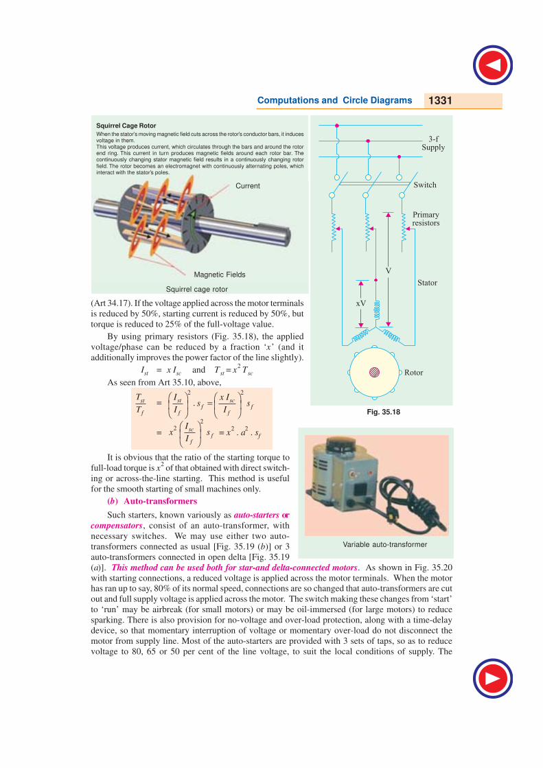
Squirrel Cage Rotor
When the stator’s moving magnetic field cuts across the rotor’s conductor bars, it inducesvoltage in them.This voltage produces current, which circulates through the bars and around the rotorend ring. This current in turn produces magnetic fields around each rotor bar. Thecontinuously changing stator magnetic field results in a continuously changing rotor
field. The rotor becomes an electromagnet with continuously alternating poles, whichinteract with the stator’s poles.
Magnetic Fields
Current
Squirrel cage rotor
(Art 34.17). If the voltage applied across the motor terminals
is reduced by 50%, starting current is reduced by 50%, but
torque is reduced to 25% of the full-voltage value.
By using primary resistors (Fig. 35.18), the applied
voltage/phase can be reduced by a fraction ‘x’ (and it
additionally improves the power factor of the line slightly).
Ist = x Isc and Tst = x2 Tsc
As seen from Art 35.10, above,
st
f
T
T=
2 2
. =
st scf f
f f
I x Is s
I I
=
22
scf
f
Ix s
I = x
2 . a
2 . sf
It is obvious that the ratio of the starting torque to
full-load torque is x2 of that obtained with direct switch-
ing or across-the-line starting. This method is useful
for the smooth starting of small machines only.
(b) Auto-transformers
Such starters, known variously as auto-starters or
compensators, consist of an auto-transformer, with
necessary switches. We may use either two auto-
transformers connected as usual [Fig. 35.19 (b)] or 3
auto-transformers connected in open delta [Fig. 35.19
(a)]. This method can be used both for star-and delta-connected motors. As shown in Fig. 35.20
with starting connections, a reduced voltage is applied across the motor terminals. When the motorhas ran up to say, 80% of its normal speed, connections are so changed that auto-transformers are cut
out and full supply voltage is applied across the motor. The switch making these changes from ‘start’
to ‘run’ may be airbreak (for small motors) or may be oil-immersed (for large motors) to reduce
sparking. There is also provision for no-voltage and over-load protection, along with a time-delay
device, so that momentary interruption of voltage or momentary over-load do not disconnect the
motor from supply line. Most of the auto-starters are provided with 3 sets of taps, so as to reduce
voltage to 80, 65 or 50 per cent of the line voltage, to suit the local conditions of supply. The
Fig. 35.18
3-fSupply
Switch
Primaryresistors
Stator
Rotor
xV
V
Variable auto-transformer

1332 Electrical Technology
V -connected auto-transformer is commonly used, because it is cheaper, although the currents are
unbalanced during starting period. This is, however, not much objectionable firstly, because the
current imbalance is about 15 per cent and secondly, because balance is restored as soon as running
conditions are attained.
The quantitative relationships between the motor current, line current, and torque developed can
be understood from Fig.35.20.
In Fig 35.20 (a) is shown the case when the motor is direct-switched to lines. The motor currentis, say, 5 times the full-load current. If V is the line voltage, then voltage/phase across motor is / 3V .
∴ Isc = 5 If = 3
V
Z where Z is stator impedance/phase.
In the case of auto-transformer, if a tapping of transformation ratio K is used, then phase voltage
across motor is KV / 3 , as marked in Fig. 35.20 (b).
∴ motor current at starting I2 =3
KV
Z = K .
3
V
Z = K . Isc = K . 5 If
3-Supply
3-Supply
RotorRotor
xV xV
Start Start
Run Run
Stator Stator
( )a ( )b
v
V
3
V
3
KV
3V V
Stator Auto-transformer Stator
Z Z
Isc f= 5I I1I2
(a)(b)
Fig. 35.20
Fig. 35.19
Computations and Circle Diagrams 1333
The current taken from supply or by auto-transformer is I1 = K I2 = K2 × 5 If = K
2 Isc if magnetising
current of the transformer is ignored. Hence, we find that although motor current per phase is re-
duced only K times the direct-switching current (∵ K < 1), the current taken by the line is reduced K2
times.
Now, remembering that torque is proportional to the square of the voltage, we get
With direct-switching, T1 ∝ (V / 3 )2; With auto-transformer, T2 ∝ (KV / 3 )
2
∴ T2 /T1 = (KV / 3 )2/(V / 3 )
2or T2 = K
2T1 or Tst = K
2 . Tsc
∴ torque with auto-starter = K2 × torque with direct-switching.
Relation Between Starting and F.L. Torque
It is seen that voltage across motor phase on direct-switching is V / 3 and starting current is Ist =
Isc. With auto-starter, voltage across motor phase is K V/ 3 and Ist = K Isc
Now, Tst ∝ Ist
2 (s = 1) and Tf ∝
2
2
f
f
I
s
∴ st
f
T
T =
2
stf
f
Is
Ior st
f
T
T = K
2
2
sc
f
I
Isf = K
2 . a
2 . sf (∵ Ist = K Isc)
Note that this expression is similar to the one derived in Art. 34.11. (a) except that x has been
replaced by transformation ratio K.
Example 35.10. Find the percentage tapping required on an auto-transformer required for a
squirrel-cage motor to start the motor against 1/4 of full-load torque. The short-circuit current on
normal voltage is 4 times the full-load current and the full-load slip is 3%.
Solution. st
f
T
T= 1
4 , sc
f
I
I = 4, sf = 0.03
∴ Using st
f
T
T= K
2 2
scf
f
Is
I , we get 1
4 = K
2 × 4
2 × 0.03
∴ K2
=1
64 0.03× ∴ K = 0.722 or K = 72.2%
Example 35.11. A 20 h.p. (14.92 kW), 400-V, 950 r.p.m., 3-φ, 50-Hz, 6-pole cage motor with
400 V applied takes 6 times full-load current at standstill and develops 1.8 times full-load runningtorque. The full-load current is 30 A.
(a) what voltage must be applied to produce full-load torque at starting ?
(b) what current will this voltage produce ?
(c) if the voltage is obtained by an auto-transformer, what will be the line current ?
(d) if starting current is limited to full-load current by an auto-transformer, what will be thestarting torque as a percentage of full-load torque ?
Ignore the magnetising current and stator impedance drops.
Solution. (a) Remembering that T ∝ V2, we have
In the first case, 1.8 T f ∝ 4002, ; In the second case, Tf ∝ V
2
∴ ( )2
400
V=
1
1.8or V =
400
1.8 = 298.1 V
(b) Currents are proportional to the applied voltage.
∴ 6 If ∝ 400 ; I ∝ 298.1 ∴ I = 6 × 298.1
400, If =
6 298.1 30
400
× × = 134.2 A

1334 Electrical Technology
(c) Here K = 298.1/400
Line current = K2 Isc = (298.1/400)
2 × 6 × 30 = 100 A
(d) We have seen in Art. 33.11 (b) that line current = K2Isc
Now, line current = full-load current If (given)
∴ 30 = K2 × 6 × 30 ∴ K
2 = 1/6
Now, using st
f
T
T=
22 ×
sc
ff
IK s
I we get st
f
T
T =
261
0.056
× ×
f
f
I
I = 0.3
Here Ns = 120 × 50/6 = 1000 r.p.m. N = 950 r.p.m.; sf = 50/1000 = 0.05
∴ Tst = 0.3 Tf or 30% F.L. torque
Example 35.12. Determine the suitable auto-transformation ratio for starting a 3-phase inductionmotor with line current not exceeding three times the full-load current. The short-circuit current is 5times the full-load current and full-load slip is 5%.
Estimate also the starting torque in terms of the full-load torque.
(Elect. Engg.II, Bombay Univ. 1987)
Solution. Supply line current = K2 Isc
It is given that supply line current at start equals 3 If and short-circuit current Isc = 5 If where If
is the full-load current
∴ 3 If = K2 × 5 If or K
2 = 0.6 ∴ K = 0.775 or 77.5%
In the case of an auto starter,
st
f
T
T=
22 ×
sc
ff
IK s
I∴ st
f
T
T = 0.6 ×
25
f
f
I
I × 0.05 = 0.75
∴ Tst = 0.75 T f = 75% of full-load torque.
Example 35.13. The full-load slip of a 400-V, 3-phase cage induction motor is 3.5% and with
locked rotor, full-load current is circulated when 92 volt is applied between lines. Find necessary
tapping on an auto-transformer to limit the starting current to twice the full-load current of the
motor. Determine also the starting torque in terms of the full-load torque.
(Elect. Machines, Banglore Univ. 1991)
Solution. Short-circuit current with full normal voltage applied is
Isc = (400/92) If = (100/23) If
Supply line current = Ist = 2 If
Now, line current Ist = K2 Isc
∴ 2 If = K2 × (100/23) If ∴ K
2 = 0.46 ; K = 0.678 or 67.8%
Also, st
f
T
T=
22 ×
sc
ff
IK s
I = 0.46 × (100/23)
2 × 0.035 = 0.304
∴ Tst = 30.4% of full-load torque
Tutorial Problems 35.2
1. A 3-φ motor is designed to run at 5% slip on full-load. If motor draws 6 times the full-load current
at starting at the rated voltage, estimate the ratio of starting torque to the full-load torque.
[1.8] (Electrical Engineering Grad, I.E.T.E. Dec. 1986)
2. A squirrel-cage induction motor has a short-circuit current of 4 times the full-load value and has a
full-load slip of 5%. Determine a suitable auto-transformer ratio if the supply line current is not to
Computations and Circle Diagrams 1335
exceed twice the full-load current. Also, express the starting torque in terms of the full-load torque.
Neglect magnetising current. [70.7%, 0.4]
3. A 3-φ, 400-V, 50-Hz induction motor takes 4 times the full-load current and develops twice the full-
load torque when direct-switched to 400-V supply. Calculate in terms of full-load values (a) the line
current, the motor current and starting torque when started by an auto-starter with 50% tap and (b)
the voltage that has to be applied and the motor current, if it is desired to obtain full-load torque on
starting. [(a) 100%, 200%, 50% (b) 228 V, 282%]
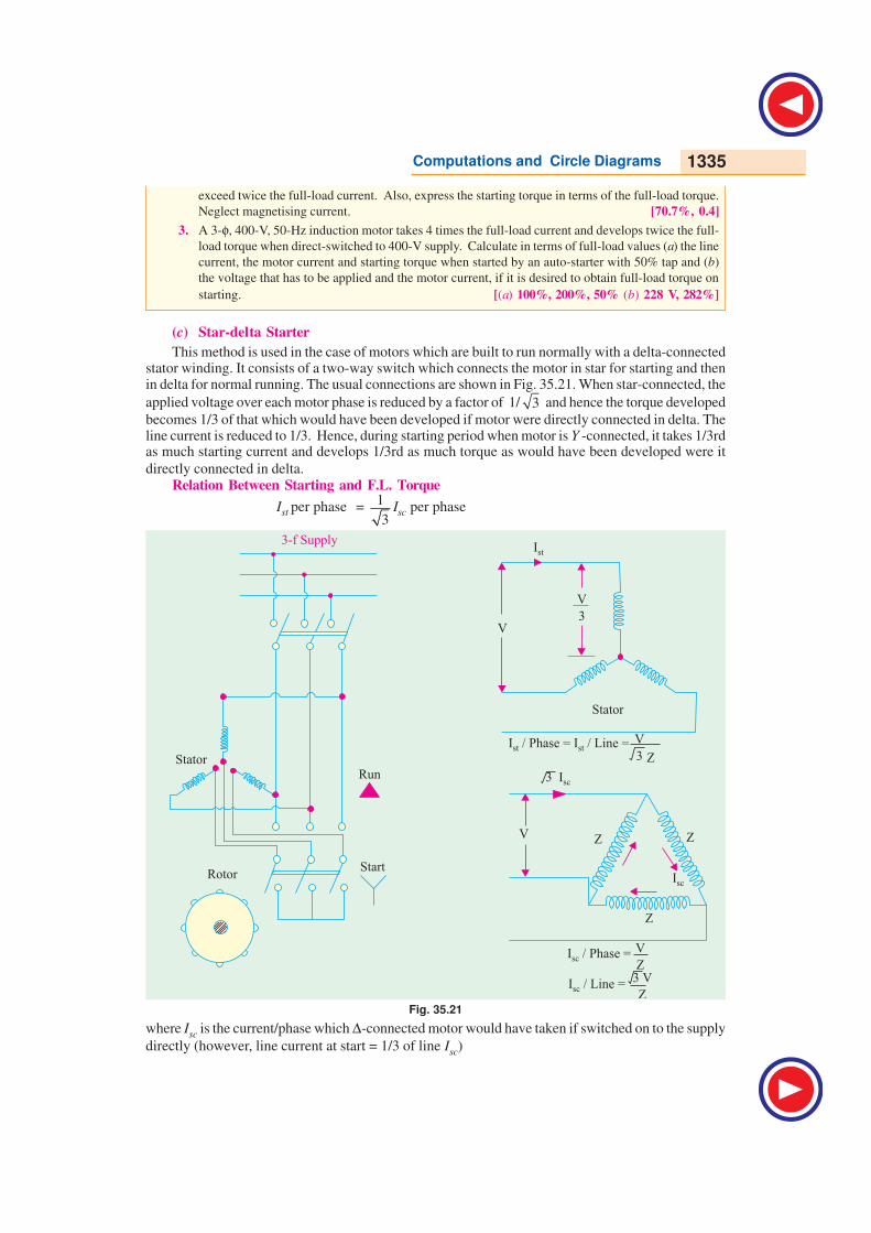
(c) Star-delta Starter
This method is used in the case of motors which are built to run normally with a delta-connectedstator winding. It consists of a two-way switch which connects the motor in star for starting and thenin delta for normal running. The usual connections are shown in Fig. 35.21. When star-connected, the
applied voltage over each motor phase is reduced by a factor of 1/ 3 and hence the torque developed
becomes 1/3 of that which would have been developed if motor were directly connected in delta. Theline current is reduced to 1/3. Hence, during starting period when motor is Y -connected, it takes 1/3rdas much starting current and develops 1/3rd as much torque as would have been developed were it
directly connected in delta.Relation Between Starting and F.L. Torque
Ist per phase = 1
3Isc per phase
Fig. 35.21
where Isc is the current/phase which ∆-connected motor would have taken if switched on to the supply
directly (however, line current at start = 1/3 of line Isc)
3-f Supply
Rotor
V
3
V
3
V
Z3 V
Z
V
Stator
Ist
3 Isc
Start
RunStator
I / Phase = I / Line =st st
I / Phase =sc
I / Line =sc
Z
V Z Z
Z
Isc
1336 Electrical Technology
Now Tst ∝ Ist
2 (s = 1 ) – Art. 35.10
Tf ∝ If
2/sf
∴ st
f
T
T=
2 2 221 1
3 33
= = =
st sc scf f f f
f ff
I I Is s s a s
I II
Here, Ist and Isc represent phase values.
It is clear that the star-delta swith is equivalent* to an auto-transformer of ratio 1/ 3 or 58%
approximately.
This method is cheap and effective provided the starting torque is required not to be more than
1.5 times the full-load torque. Hence, it is used for machine tools, pumps and motor-generators etc.
Example 35.14. The full-load efficiency and power factor of a 12-kW, 440-V, 3-phase induction
motor are 85% and 0.8 lag respectively. The blocked rotor line current is 45 A at 220 V. Calculate
the ratio of starting to full-load current, if the motor is provided with a star-delta starter. Neglect
magnetising current. (Elect. Machines, A.M.I.E. Sec. B, 1991)
Solution. Blocked rotor current with full voltage applied
Isc = 45 × 440/220 = 90 A
Now, 3 × 440 × If × 0.8 = 12,000/0.85, ∴ If = 23.1 A
In star-delta starter, Ist = Isc / 3 = 90 / 3 = 52 A
∴ Ist / If = 52 / 23.1 = 2.256
Example 35.15. A 3-phase, 6-pole, 50-Hz induction motor takes 60 A at full-load speed of 940
r.p.m. and develops a torque of 150 N-m. The starting current at rated voltage is 300 A. What is the
starting torque? If a star/delta starter is used, determine the starting torque and starting current.
(Electrical Machinery-II, Mysore Univ. 1988)
Solution. As seen from Art. 33.10, for direct-switching of induction motors
st
f
T
T=
2
sc
f
I
I sf. Here, Ist = Isc = 300 A (line value) ; If = 60 A (line value),
sf = (1000 − 940)/1000 = 0.06 ; Tf = 150 N-m
∴ Tst = 150(300/60)2 × 0.06 = 225 N-m
When star/delta starter is used
Starting current = 1/3 × starting current with direct starting = 300/3 = 100 A
Starting torque = 225/3 = 75 N-m –Art 35-11 (c)
Example 35.16. Determine approximately the starting torque of an induction motor in terms of
full-load torque when started by means of (a) a star-delta switch (b) an auto-transformer with 70.7
% tapping. The short-circuit current of the motor at normal voltage is 6 times the full-load current
and the full-load slip is 4%. Neglect the magnetising current.
(Electrotechnics, M.S. Univ. Baroda 1986)
Solution. (a) st
f
T
T=
221 1
6 0.04 0.483 3
= × × =
scf
f
Is
I
∴ Tst = 0.48 Tf or 48% of F.L. value
(b) Here K = 0.707 = 1/ 2 ; K2
= 1/2
* By comparing it with the expression given in Art. 35.11 (b)
Computations and Circle Diagrams 1337
Now, st
f
T
T= K
2
2
sc
f
I
Isf =
1
2 × 6
2 × 0.04 = 0.72
∴ Tst = 0.72 T f or 72% of Tf
Example 35.17. A 15 h.p. (11.2 kW), 3-φ, 6-pole, 50-HZ, 400-V, ∆-connected induction motor
runs at 960 r.p.m. on full-load. If it takes 86.4 A on direct starting, find the ratio of starting torque to
full-load torque with a star-delta starter. Full-load efficiency and power factor are 88% and 0.85
respectively.
Solution. Here, Isc/phase = 86.4/ 3 A
Ist per phase = 1
3 . Isc per phase =
86.4
3 3× = 28.8 A
Full-load input line current may be found from
3 × 400 × IL × 0.85 = 11.2 × 10³/0.88 ∴ Full-load IL = 21.59 A
F.L. Iph = 21.59/ 3 A ; If = 21.59/ 3 A per phase
Ns = 120 × 50/6 = 1000 r.p.m., N = 950 ; sf = 0.05
st
f
T
T =
2
st
f
I
I sf =
228.8 3
21.59
×
× 0.05 ∴ Tst = 0.267 Tf or 26.7% F.L. torque
Example 35.18. Find the ratio of starting to full-load current in a 10 kW (output), 400-V, 3-
phase induction motor with star/delta starter, given that full-load p.f. is 0.85, the full-load efficiencyis 0.88 and the blocked rotor current at 200 V is 40 A. Ignore magnetising current.
(Electrical Engineering, Madras Univ. 1985)
Solution. F.L. line current drawn by the ∆-connected motor may be found from
3 × 400 × IL × 0.85 = 10 × 1000/0.88 ∴ IL = 19.3 A
Now, with 200 V, the line value of S.C. current of the ∆-connected motor is 40 A. If full normalvoltage were applied, the line value of S.C. current would be = 40 × ( 400/200) = 80 A.
∴ Isc (line value) = 80 A ; Isc (phase value) = 80/ 3 A
When connected in star across 400 V, the starting current per phase drawn by the motor stator
during starting is
Ist per phase =1
3 × Isc per phase =
1 80 80A
33 3× = –Art. 35.10
Since during starting, motor is star-connected, Ist per phase = line value of Isc = 80/3A
∴ line value of starting current
line value of F.L. current = 80 / 3
19.3 = 1.38
Example 35.19. A 5 h.p. (3.73 kW), 400-V, 3-φ, 50-Hz cage motor has a full-load slip of 4.5%.
The motor develops 250% of the rated torque and draws 650% of the rated current when throwndirectly on the line. What would be the line current, motor current and the starting torque if themotor were started (i) be means of a star/delta starter and (ii) by connecting across 60% taps of astarting compensator. (Elect. Machines-II, Indore Univ. 1989)
Solution. (i) Line current = (1/3) × 650 = 216.7%
Motor being star-connected, line current is equal to phase current.
∴ motor current = 650/3 = 216.7%
As shown earlier, starting torque developed for star-connection is one-third of that developed ondirect switching with delta-connection ∴ Tst = 250/3 = 83.3%
(ii) Line current = K2 × Isc = (60/100)
2 × 650 = 234%

1338 Electrical Technology
Motor current = K × Isc = (60/100) × 650 = 390%
Tst = K2 × Tsc = (60/100)
2 × 250 = 90%
Example. 35.20. A squirrel-cage type induction motor when started by means of a star/delta
starter takes 180% of full-load line current and develops 35% of full-load torque at starting. Calcu-
lated the starting torque and current in terms of full-load values, if an auto-transformer with 75%
tapping were employed. (Utilization of Elect. Power, A.M.I.E. 1987)
Solution. With star-delta starter, st
f
T
T =
21
3
scf
f
Is
I
Line current on line-start Isc = 3 × 180% of If = 3 × 1.8 If = 5.4 If
Now, Tst /Tf = 0.35 (given) ; Isc /If = 5.4
∴ 0.35 = (1/3) × 5.42 sf or 5.4
2 sf = 1.05
Autostarter : Here, K = 0.75
Line starting current = K2 Isc = (0.75)
2 × 5.4 If = 3.04 If = 304% of F.L. current
st
f
T
T=
22
scf
f
IK s
I; st
f
T
T = (0.75)
2 × 5.4
2 sf
= (0.75)2 × 1.05 = 0.59
Tst = 0.59 T f = 59% F.L. torque
Example. 35.21. A 10 h.p. (7.46 kW) motor when started at normal voltage with a star-delta
switch in the star position is found to take an initial current of 1.7 × full-load current and gave an
initial starting torque of 35% of full-load torque. Explain what happens when the motor is started
under the following conditions : (a) an auto-transformer giving 60% of normal voltage (b) a resis-
tance in series with the stator reducing the voltage to 60% of the normal and calculate in each case
the value of starting current and torque in terms of the corresponding quantities at full-load.
(Elect. Machinery-III, Kerala Univ. 1987)
Solution. If the motor were connected in delta and direct-switched to the line, then it would take
a line current three times that which it takes when star-connected.∴ line current on line start or Isc = 3 × 1.7 If = 5.1 If
We know st
f
T
T=
21
3
sc
f
I
Isf
Now st
f
T
T= 0.35 ...given ; sc
f
I
I = 5.1 ...calculated
∴ 0.35 = (1/3) × 5.12 × sf
We can find sf from 5.12 × sf = 1.05
(a) When it is started with an auto-starter, then K = 0.6
Line starting current = K2 × Isc = 0.6
2 × 5.1 If = 0.836 If
Tst/Tf = 0.62 × 5.1
2 × sf = 0.6
2 × 1.05 = 0.378 ∴ Tst = 37.8% of F.L. torque
(b) Here, voltage across motor is reduced to 60% of normal value. In this case motor current is
the same as line current but it decreases in proportion to the decrease in voltage.
As voltage across motor = 0.6 of normal voltage
∴ line starting current = 0.6 × 5.1 If = 3.06 If
Torque at starting would be the same as before.
Tst /Tf = 0.62 × 5.1
2 × sf = 0.378 ∴ Tst = 37.8% of F.L. torque.
Computations and Circle Diagrams 1339
Tutorial Problems 35.3
1. A 3-phase induction motor whose full-load slip is 4 per cent, takes six times full-load current when
switched directly on to the supply. Calculate the approximate starting torque in terms of the full-load
torque when started by means of an auto-transformer starter, having a 70 percent voltage tap.
[0.7 Tf ]
2. A 3-phase, cage induction motor takes a starting current at normal voltage of 5 times the full-load
value and its full-load slip is 4 per cent. What auto-transformer ratio would enable the motor to be
started with not more than twice full-load current drawn from the supply ?
What would be the starting torque under these conditions and how would it compare with that
obtained by using a stator resistance starter under the same limitations of line current ?
[63.3% tap ; 0.4 Tf ; 0.16 Tf ]
3. A 3-phase, 4-pole, 50-Hz induction motor takes 40 A at a full-load speed of 1440 r.p.m. and develops
a torque of 100 N-m at full-load. The starting current at rated voltage is 200 A. What is the starting
torque ? If a star-delta starter is used, what is the starting torque and starting current ? Neglect
magnetising current.
[100 N-m; 33.3 N-m; 66.7 A] (Electrical Machines-IV, Bangalore Univ. Aug. 1978)
4. Determine approximately the starting torque of an induction motor in terms of full-load torque when
started by means of (a) a star-delta switch (b) an auto-transformer with 50% tapping. Ignore
magnetising current. The short-circuit current of the motor at normal voltage is 5 times the full-load
current and the full-load slip is 4 per cent. [(a) 0.33 (b) 0.25] (A.C. Machines, Madras Univ. 1976)
5. Find the ratio of starting to full-load current for a 7.46 kW, 400-V, 3-phase induction motor with star/
delta starter, given that the full-load efficiency is 0.87, the full-load p.f. is 0.85 and the short-circuit
current is 15 A at 100 V. [1.37] (Electric Machinery-II, Madras Univ. April 1978)
6. A four-pole, 3-phase, 50-Hz, induction motor has a starting current which is 5 times its full-load
current when directly switched on. What will be the percentage reduction in starting torque if (a)
star-delta switch is used for starting (b) auto-transformer with a 60 per cent tapping is used for
starting ? (Electrical Technology-III, Gwalior Univ. Nov. 1917)
7. Explain how the performance of induction motor can be predicted by circle diagram. Draw the circle
diagram for a 3-phase, mesh-connected, 22.38 kW, 500-V, 4-pole, 50-Hz induction motor. The data
below give the measurements of line current, voltage and reading of two wattmeters connected to
measure the input :
No load 500 V 8.3 A 2.85 kW − 1.35 kW
Short circuit 100 V 32 A − 0.75 kW 2.35 kW
From the diagram, find the line current, power factor, efficiency and the maximum output.
[83 A, 0.9, 88%, 50.73 kW] (Electrical Machines-II, Vikram Univ. Ujjan 1977)
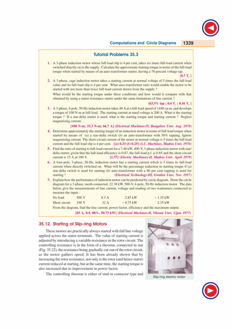
35.12. Starting of Slip-ring Motors
These motors are practically always started with full line voltage
applied across the stator terminals. The value of starting current is
adjusted by introducing a variable resistance in the rotor circuit. The
controlling resistance is in the form of a rheostat, connected in star
(Fig. 35.22), the resistance being gradually cut-out of the rotor circuit,
as the motor gathers speed. It has been already shown that by
increasing the rotor resistance, not only is the rotor (and hence stator)
current reduced at starting, but at the same time, the starting torque is
also increased due to improvement in power factor.
The controlling rheostat is either of stud or contactor type andSlip-ring electric motor

1340 Electrical Technology
3- Supply
Stator
Switch
RheostatSlip RingsRotor
may be hand-operated or automatic. The starter unit usually
includes a line switching contactor for the stator along with no-
voltage (or low- voltage) and over-current protective devices.
There is some form of interlocking to ensure proper sequential
operation of the line contactor and the starter. This interlocking
prevents the closing of stator contactor unless the starter is ‘all
in’.
As said earlier, the introduction of additional external
resistance in the rotor circuit enables a slip-ring motor to develop
a high starting torque with reasonably moderate starting current.
Hence, such motors can be started under load. This additional
resistance is for starting purpose only. It is gradually cut out as the
motor comes up to speed.
Fig. 35.22
The rings are, later on, short-circuited and brushes lifted from them when motor runs under
normal conditions.
35.13. Starter Steps
Let it be assumed, as usually it is in the case of starters, that (i) the motor starts against a constant
torque and (ii) that the rotor current fluctuates between fixed maximum and minimum values of I2max
and I2min respectively.
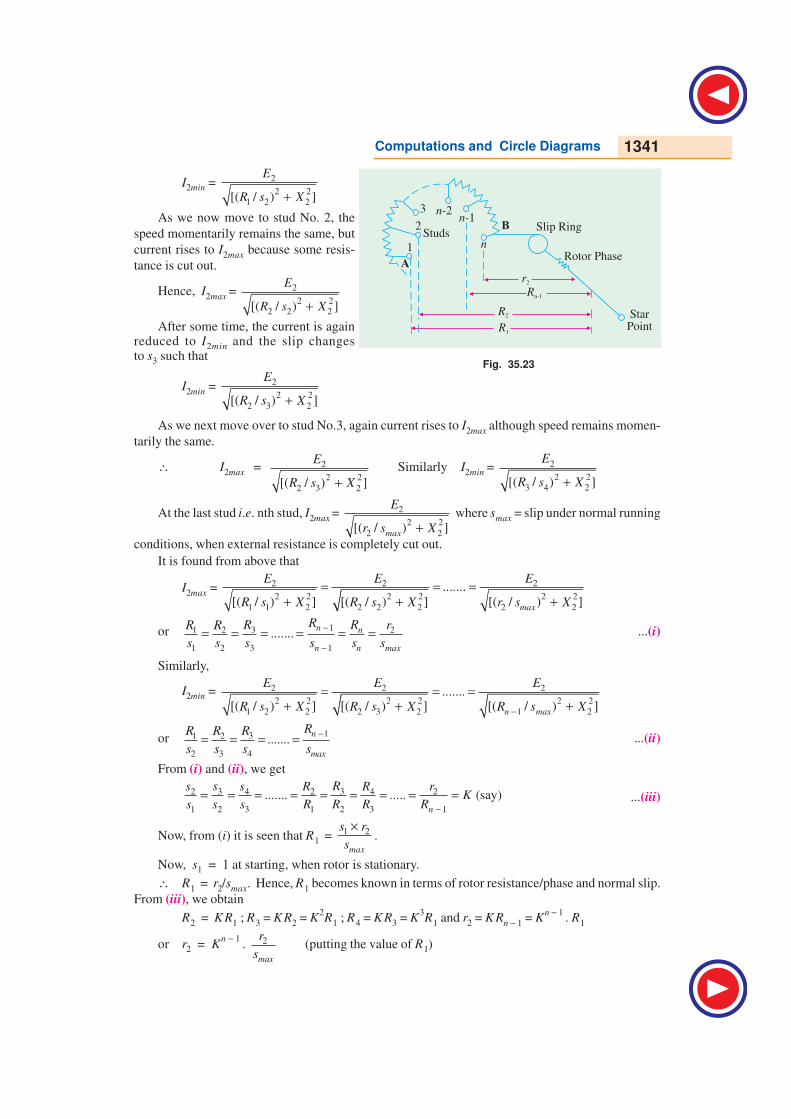
In Fig. 35.23 is shown one phase of the 3-phase rheostat AB having n steps and the rotor circuit.
Let R1, R2 ....etc. be the total resistances of the rotor circuit on the first, second step...etc. respectively.
The resistances R1, R2 ..., etc. consist of rotor resistance per phase r2 and the external resistances ρ1,
ρ2 .... etc. Let the corresponding values of slips be s1, s2 ...etc. at stud No.1, 2...etc. At the
commencement of each step, the current is I2max and at the instant of leaving it, the current is I2min .
Let E2 be the standstill e.m.f. induced in each phase of the rotor. When the handle touches first stud,
the current rises to a maximum value I2max, so that
I2max = 1 2 2
2 2 2 2
1 1 2 1 1 2[ ( ) ] [( / ) ]=
+ +
s E E
R s X R s X
where s1 = slip at starting i.e. unity and X 2 = rotor reactance/phase
Then, before moving to stud No. 2, the current is reduced to I2min and slip changes to s2 such that
Rheostat
Computations and Circle Diagrams 1341
I2min = 2
2 2
1 2 2[( / ) ]+
E
R s X
As we now move to stud No. 2, the
speed momentarily remains the same, but
current rises to I2max because some resis-
tance is cut out.
Hence, I2max = 2
2 2
2 2 2[( / ) ]+
E
R s X
After some time, the current is againreduced to I2min and the slip changesto s3 such that
I2min = 2
2 2
2 3 2[( / ) ]+
E
R s X
As we next move over to stud No.3, again current rises to I2max although speed remains momen-
tarily the same.
∴ I2max = 2
2 2
2 3 2[( / ) ]+
E
R s X
Similarly I2min = 2
2 2
3 4 2[( / ) ]+
E
R s X
At the last stud i.e. nth stud, I2max = 2
2 2
2 2[( / ) ]+
max
E
r s X
where smax = slip under normal running
conditions, when external resistance is completely cut out.
It is found from above that
I2max = 2 2 2
2 2 2 2 2 2
1 1 2 2 2 2 2 2
.......[( / ) ] [( / ) ] [( / ) ]
max
E E E
R s X R s X r s X
= = =+ + +
or 131 2 2
1 2 3 1
.......−
−= = = = = =n n
n n max
RR RR R r
s s s s s s...(i)
Similarly,
I2min = 2 2 2
2 2 2 2 2 2
1 2 2 2 3 2 1 2
.......[( / ) ] [( / ) ] [( / ) ]−
= = =+ + +
n max
E E E
R s X R s X R s X
or 131 2
2 3 4
.......−= = = = n
max
RRR R
s s s s...(ii)
From (i) and (ii), we get
3 32 4 2 4 2
1 2 3 1 2 3 1
....... ..... (say)−
= = = = = = = = =n
s Rs s R R rK
s s s R R R R...(iii)
Now, from (i) it is seen that R1 = 1 2×
max
s r
s.
Now, s1 = 1 at starting, when rotor is stationary.
∴ R1 = r2/smax. Hence, R1 becomes known in terms of rotor resistance/phase and normal slip.
From (iii), we obtain
R2 = KR1 ; R3 = KR2 = K2R1 ; R4 = KR3 = K
3R1 and r2 = KRn − 1 = K
n − 1 . R1
or r2 = Kn − 1
. 2
max
r
s(putting the value of R1)
Fig. 35.23
r2
R2
R1
Rn-1
StarPoint
Rotor Phase
Slip RingBStuds
A
1
2
3 n-2n-1
n
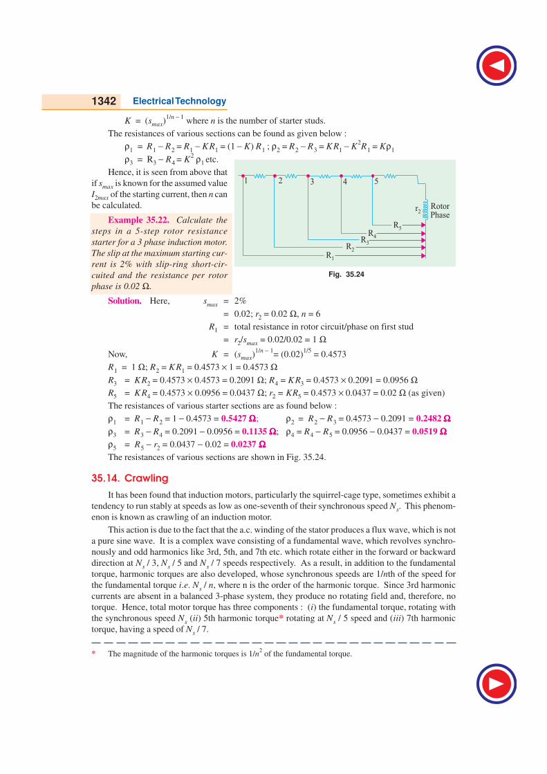
1342 Electrical Technology
K = (smax)1/n − 1
where n is the number of starter studs.
The resistances of various sections can be found as given below :
ρ1 = R1 − R2 = R1 − KR1 = (1 − K) R1 ; ρ2 = R2 − R3 = KR1 − K2R1 = Kρ1
ρ3 = R3 − R4 = K2 ρ1 etc.
Hence, it is seen from above that
if smax is known for the assumed value
I2max of the starting current, then n can
be calculated.
Example 35.22. Calculate the
steps in a 5-step rotor resistance
starter for a 3 phase induction motor.
The slip at the maximum starting cur-
rent is 2% with slip-ring short-cir-
cuited and the resistance per rotor
phase is 0.02 Ω.
Solution. Here, smax = 2%
= 0.02; r2 = 0.02 Ω, n = 6
R1 = total resistance in rotor circuit/phase on first stud
= r2/smax = 0.02/0.02 = 1 Ω
Now, K = (smax)1/n − 1
= (0.02)1/5
= 0.4573
R1 = 1 Ω; R2 = KR1 = 0.4573 × 1 = 0.4573 ΩR3 = KR2 = 0.4573 × 0.4573 = 0.2091 Ω; R4 = KR3 = 0.4573 × 0.2091 = 0.0956 ΩR5 = KR4 = 0.4573 × 0.0956 = 0.0437 Ω; r2 = KR5 = 0.4573 × 0.0437 = 0.02 Ω (as given)
The resistances of various starter sections are as found below :
ρ1 = R1 − R2 = 1 − 0.4573 = 0.5427 ΩΩΩΩΩ; ρ2 = R2 − R3 = 0.4573 − 0.2091 = 0.2482 ΩΩΩΩΩρ3 = R3 − R4 = 0.2091 − 0.0956 = 0.1135 ΩΩΩΩΩ; ρ4 = R4 − R5 = 0.0956 − 0.0437 = 0.0519 ΩΩΩΩΩρ5 = R5 − r2 = 0.0437 − 0.02 = 0.0237 ΩΩΩΩΩThe resistances of various sections are shown in Fig. 35.24.
35.14. Crawling
It has been found that induction motors, particularly the squirrel-cage type, sometimes exhibit a
tendency to run stably at speeds as low as one-seventh of their synchronous speed Ns. This phenom-
enon is known as crawling of an induction motor.
This action is due to the fact that the a.c. winding of the stator produces a flux wave, which is not
a pure sine wave. It is a complex wave consisting of a fundamental wave, which revolves synchro-
nously and odd harmonics like 3rd, 5th, and 7th etc. which rotate either in the forward or backward
direction at Ns / 3, Ns / 5 and Ns / 7 speeds respectively. As a result, in addition to the fundamental
torque, harmonic torques are also developed, whose synchronous speeds are 1/nth of the speed for
the fundamental torque i.e. Ns / n, where n is the order of the harmonic torque. Since 3rd harmonic
currents are absent in a balanced 3-phase system, they produce no rotating field and, therefore, no
torque. Hence, total motor torque has three components : (i) the fundamental torque, rotating with
the synchronous speed Ns (ii) 5th harmonic torque* rotating at Ns / 5 speed and (iii) 7th harmonic
torque, having a speed of Ns / 7.
* The magnitude of the harmonic torques is 1/n2 of the fundamental torque.
Fig. 35.24
R1
R2
R3
R4
R5
r2
RotorPhase
1 2 3 4 5
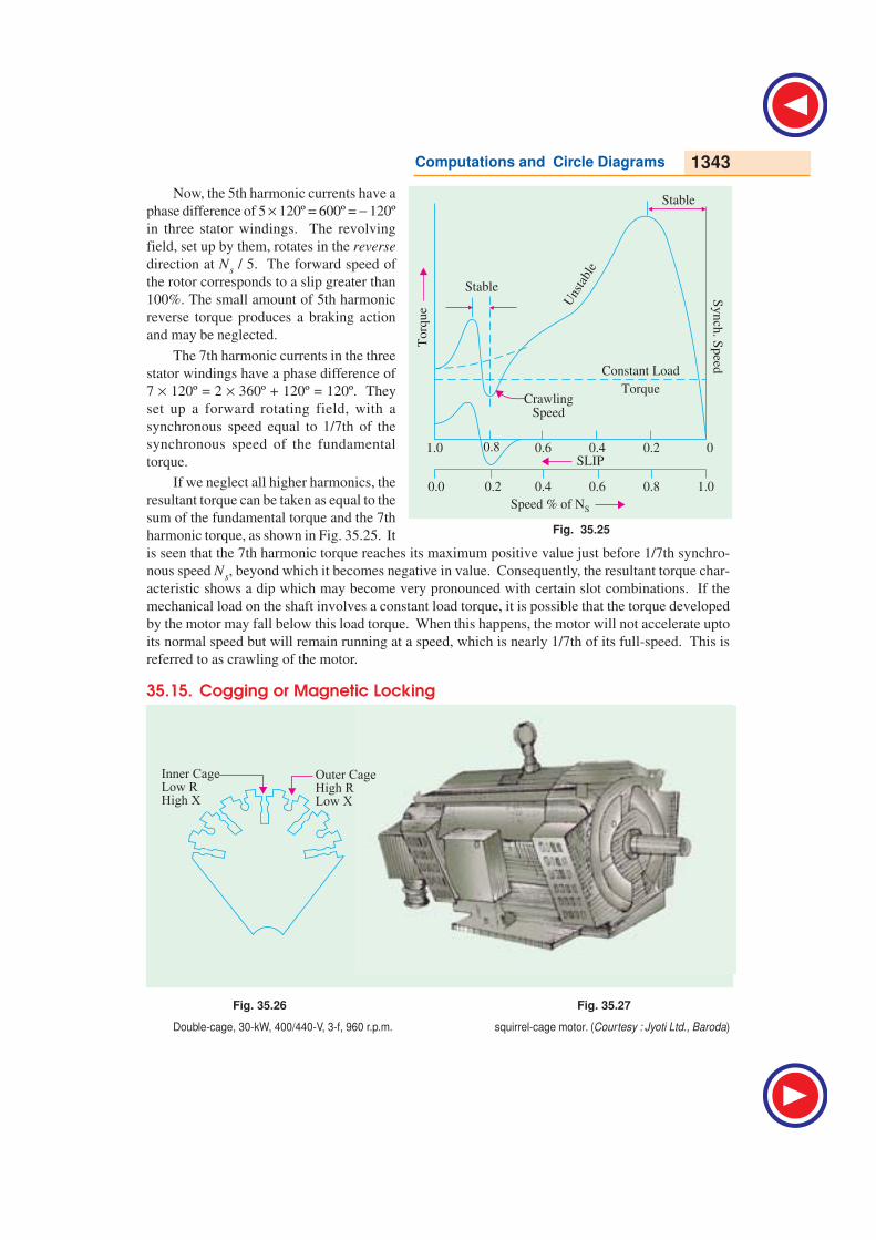
Computations and Circle Diagrams 1343
Now, the 5th harmonic currents have a
phase difference of 5 × 120º = 600º = − 120º
in three stator windings. The revolving
field, set up by them, rotates in the reverse
direction at Ns / 5. The forward speed of
the rotor corresponds to a slip greater than
100%. The small amount of 5th harmonic
reverse torque produces a braking action
and may be neglected.
The 7th harmonic currents in the three
stator windings have a phase difference of
7 × 120º = 2 × 360º + 120º = 120º. They
set up a forward rotating field, with a
synchronous speed equal to 1/7th of the
synchronous speed of the fundamental
torque.
If we neglect all higher harmonics, the
resultant torque can be taken as equal to the
sum of the fundamental torque and the 7th
harmonic torque, as shown in Fig. 35.25. It
is seen that the 7th harmonic torque reaches its maximum positive value just before 1/7th synchro-
nous speed Ns, beyond which it becomes negative in value. Consequently, the resultant torque char-
acteristic shows a dip which may become very pronounced with certain slot combinations. If the
mechanical load on the shaft involves a constant load torque, it is possible that the torque developed
by the motor may fall below this load torque. When this happens, the motor will not accelerate upto
its normal speed but will remain running at a speed, which is nearly 1/7th of its full-speed. This is
referred to as crawling of the motor.
35.15. Cogging or Magnetic Locking
Fig. 35.26 Fig. 35.27
Double-cage, 30-kW, 400/440-V, 3-f, 960 r.p.m. squirrel-cage motor. (Courtesy : Jyoti Ltd., Baroda)
Fig. 35.25
1.0
0.0
0.8
0.8
0.6
0.6
0.4
0.4
0.2
0.2
0
1.0
Stable
Stable
To
rqu
e
Sy
nch
.S
peed
CrawlingSpeed
Speed % of NS
Constant Load
Torque
Uns
tabl
e
SLIP
Inner CageLow RHigh X
Outer CageHigh RLow X
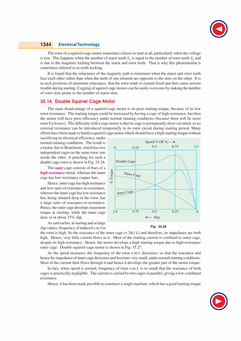
1344 Electrical Technology
The rotor of a squirrel-cage motor sometimes refuses to start at all, particularly when the voltage
is low. This happens when the number of stator teeth S1 is equal to the number of rotor teeth S2 and
is due to the magnetic locking between the stator and rotor teeth. That is why this phenomenon is
sometimes referred to as teeth-locking.
It is found that the reluctance of the magnetic path is minimum when the stator and rotor teeth
face each other rather than when the teeth of one element are opposite to the slots on the other. It is
in such positions of minimum reluctance, that the rotor tends to remain fixed and thus cause serious
trouble during starting. Cogging of squirrel cage motors can be easily overcome by making the number
of rotor slots prime to the number of stator slots.
35.16. Double Squirrel Cage Motor
The main disadvantage of a squirrel-cage motor is its poor starting torque, because of its low
rotor resistance. The starting torque could be increased by having a cage of high resistance, but then
the motor will have poor efficiency under normal running conditions (because there will be more
rotor Cu losses). The difficulty with a cage motor is that its cage is permanently short-circuited, so no
external resistance can be introduced temporarily in its rotor circuit during starting period. Many
efforts have been made to build a squirrel-cage motor which should have a high starting torque without
sacrificing its electrical efficiency, under
normal running conditions. The result is
a motor, due to Boucheort, which has two
independent cages on the same rotor, one
inside the other. A punching for such a
double cage rotor is shown in Fig. 35.26.
The outer cage consists of bars of a
high-resistance metal, whereas the inner
cage has low-resistance copper bars.
Hence, outer cage has high resistance
and low ratio of reactance-to-resistance,
whereas the inner cage has low resistance
but, being situated deep in the rotor, has
a large ratio of reactance-to-resistance.
Hence, the outer cage develops maximum
torque at starting, while the inner cage
does so at about 15% slip.
As said earlier, at starting and at large
slip values, frequency of induced e.m.f in
the rotor is high. So the reactance of the inner cage (= 2π f L) and therefore, its impedance are both
high. Hence, very little current flows in it. Most of the starting current is confined to outer cage,
despite its high resistance. Hence, the motor develops a high starting torque due to high-resistance
outer cage. Double squirrel-cage motor is shown in Fig. 35.27.
As the speed increases, the frequency of the rotor e.m.f. decreases, so that the reactance and
hence the impedance of inner cage decreases and becomes very small, under normal running conditions.
Most of the current then flows through it and hence it develops the greater part of the motor torque.
In fact, when speed is normal, frequency of rotor e.m.f. is so small that the reactance of both
cages is practically negligible. The current is carried by two cages in parallel, giving a low combined
resistance.
Hence, it has been made possible to construct a single machine, which has a good starting torque
Fig. 35.28
0
00.25
0.25
0.5
0.5
0.75
0.75
1.0
1.0
%T
orq
ue
Speed % OF Ns
Outer Cage
Double Cage
Inner Cage
Slip
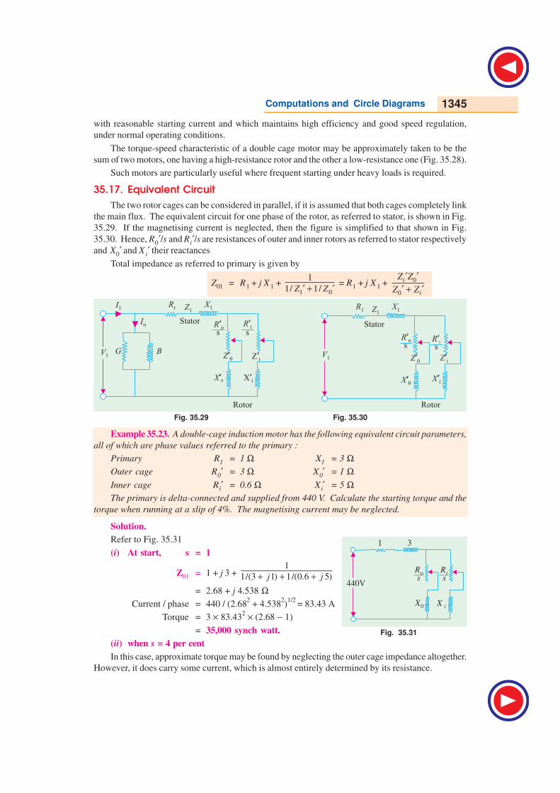
Computations and Circle Diagrams 1345
with reasonable starting current and which maintains high efficiency and good speed regulation,
under normal operating conditions.
The torque-speed characteristic of a double cage motor may be approximately taken to be the
sum of two motors, one having a high-resistance rotor and the other a low-resistance one (Fig. 35.28).
Such motors are particularly useful where frequent starting under heavy loads is required.
35.17. Equivalent Circuit
The two rotor cages can be considered in parallel, if it is assumed that both cages completely link
the main flux. The equivalent circuit for one phase of the rotor, as referred to stator, is shown in Fig.
35.29. If the magnetising current is neglected, then the figure is simplified to that shown in Fig.
35.30. Hence, R0′/s and Ri′/s are resistances of outer and inner rotors as referred to stator respectively
and X0′ and X i′ their reactances
Total impedance as referred to primary is given by
Z01 = R1 + j X 1 + 1 0
1
1/ 1/′ + ′Z Z = R1 + j X 1 + 0
0
′ ′′ + ′i
i
Z Z
Z Z
Fig. 35.29 Fig. 35.30
Example 35.23. A double-cage induction motor has the following equivalent circuit parameters,
all of which are phase values referred to the primary :
Primary R1 = 1 Ω X1 = 3 ΩOuter cage R0′ = 3 Ω X0′ = 1 ΩInner cage Ri′ = 0.6 Ω X i′ = 5 ΩThe primary is delta-connected and supplied from 440 V. Calculate the starting torque and the
torque when running at a slip of 4%. The magnetising current may be neglected.
Solution.
Refer to Fig. 35.31
(i) At start, s = 1
Z01 = 1 + j 3 + 1
1/(3 1) 1/(0.6 5)+ + +j j
= 2.68 + j 4.538 ΩCurrent / phase = 440 / (2.68
2 + 4.538
2)1/2
= 83.43 A
Torque = 3 × 83.432 × (2.68 − 1)
= 35,000 synch watt.
(ii) when s = 4 per cent
In this case, approximate torque may be found by neglecting the outer cage impedance altogether.
However, it does carry some current, which is almost entirely determined by its resistance.
Fig. 35.31
Xi
Ri
Ro
X0
1 ! 3!
440Vss
X i’ X i’
R’i
R i’
R o’
R o’
Z i’ Z i’Z 0’ Z 0’
X 0’ X 0’
Rr R1Z1 Z1
V1 V1
X1 X1
Io
I1
StatorStator
s
s
s
sG B
Rotor Rotor
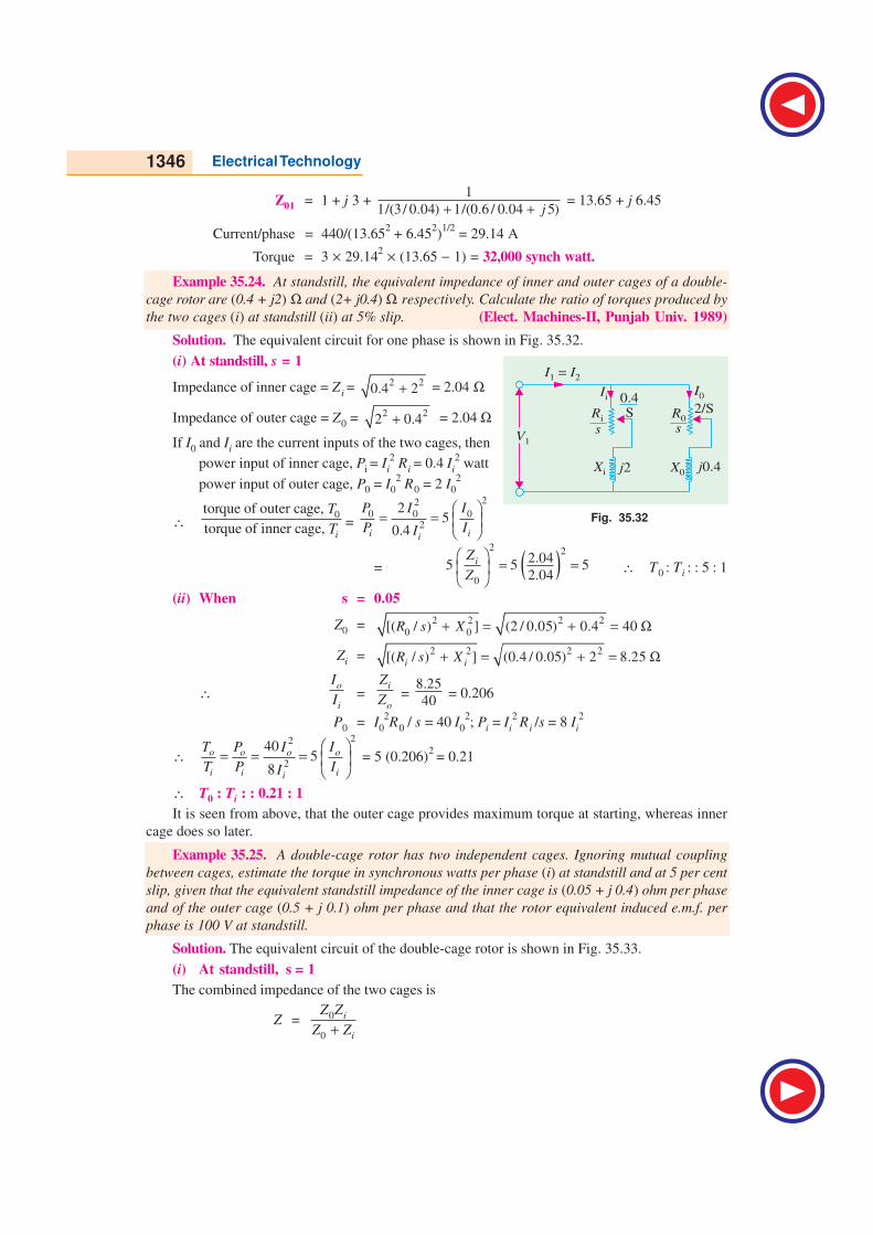
1346 Electrical Technology
Z01 = 1 + j 3 + 1
1/(3 / 0.04) 1/(0.6 / 0.04 5)+ + j = 13.65 + j 6.45
Current/phase = 440/(13.652 + 6.45
2)1/2
= 29.14 A
Torque = 3 × 29.142 × (13.65 − 1) = 32,000 synch watt.
Example 35.24. At standstill, the equivalent impedance of inner and outer cages of a double-
cage rotor are (0.4 + j2) Ω and (2+ j0.4) Ω respectively. Calculate the ratio of torques produced by
the two cages (i) at standstill (ii) at 5% slip. (Elect. Machines-II, Punjab Univ. 1989)
Solution. The equivalent circuit for one phase is shown in Fig. 35.32.
(i) At standstill, s = 1
Impedance of inner cage = Z i = 2 20.4 2+ = 2.04 Ω
Impedance of outer cage = Z0 = 2 22 0.4+ = 2.04 Ω
If I0 and Ii are the current inputs of the two cages, then
power input of inner cage, Pi = Ii
2 Ri = 0.4 Ii
2 watt
power input of outer cage, P0 = I02 R0 = 2 I0
2
∴ 0torque of outer cage,
torque of inner cage, i
T
T=
22
0 0 02
25
0.4
= =
i ii
P I I
P II
= ( )2 2
0
2.045 5 5
2.04
= =
i
Z
Z∴ T0 : Ti : : 5 : 1
(ii) When s = 0.05
Z0 = 2 2 2 2
0 0[( / ) ] (2 / 0.05) 0.4 40+ = + = ΩR s X
Zi = 2 2 2 2[( / ) ] (0.4 / 0.05) 2 8.25+ = + = Ω
i iR s X
∴o
i
I
I =i
o
Z
Z = 8.25
40 = 0.206
P0 = I0
2R0 / s = 40 I0
2; Pi = Ii
2 R i /s = 8 Ii
2
∴22
2
405
8
= = =
o o o o
i i ii
T P I I
T P II = 5 (0.206)
2 = 0.21
∴ T0 : Ti : : 0.21 : 1
It is seen from above, that the outer cage provides maximum torque at starting, whereas inner
cage does so later.
Example 35.25. A double-cage rotor has two independent cages. Ignoring mutual coupling
between cages, estimate the torque in synchronous watts per phase (i) at standstill and at 5 per cent
slip, given that the equivalent standstill impedance of the inner cage is (0.05 + j 0.4) ohm per phase
and of the outer cage (0.5 + j 0.1) ohm per phase and that the rotor equivalent induced e.m.f. per
phase is 100 V at standstill.
Solution. The equivalent circuit of the double-cage rotor is shown in Fig. 35.33.
(i) At standstill, s = 1
The combined impedance of the two cages is
Z = 0
0 +i
i
Z Z
Z Z
Fig. 35.32

Computations and Circle Diagrams 1347
where Z0 = impedance of the outer cage
Zi = impedance of the inner cage
Z =(0.5 0.1) (0.05 0.4)
(0.55 0.5)
+ ++
j j
j
= 0.1705 + j 0.191 ohm
∴ Z =2 2
0.1705 0.191+ = 0.256 Ω
Rotor current I2 = 100/0.256 A; Combined resistance R2 =
0.1705 ΩTorque at standstill in synchronous watts per phase is
= I22 R2 = ( )2
100
0.256 × 0.1705 = 26,000 synch watts
(ii) Here s = 0.05
Z =( ) ( )
( )0.5 0.05
0.1 0.40.05 0.05
0.05 0.50.5
0.5 0.05
j j
j
+ +
+ + = 1.01 + j 0.326 ohm
Z = 2 2(1.01) 0.326+ =1.06 Ω
Combined resistance R2 = 1.01 Ω ; rotor current = 100/1.06 A
Torque in synchronous watts per phase is
= I2
2 R2 = (100/1.06)
2 × 1.1 = 9,000 synch.watt.
Example 35.26. In a double-cage induction motor, if the outer cage has an impedance at
standstill of (2 + j 1.2) ohm, determine the slip at which the two cages develop equal torques if the
inner cage has an impedance of (0.5 + j 3.5) ohm at standstill.
(Electric Machines, Osmania Univ. 1991)
Solution. Let s be the slip at which two cage develop equal torques.
Then Z1 = 2 2(2 / ) 1.2+s and Z2 = 2 2
(0.5 / ) 3.5+s
∴2
1
2
I
I=
2
2
1
Z
Z =
2 2
2
(0.25 / ) 3.5
(4 / ) 1.44
++
s
s
Power input to outer cage P1 = I1
2 R1/s
∴ P1 =2
12×Is
; P2 = I22 × 0.5
s
∴ 1
2
T
T=
2 2 21 1
22 2
(0.25 / ) 3.54 4
(4 / ) 1.44
+= × = × +
P I s
P I s
As T1 = T2
∴ 2
41.44+
s=
2
0.2512.25 4
+ × s
∴ s = 0.251= 25.1%
Example 35.27. The resistance and reactance (equivalent) values of a double-cage induction
motor for stator, outer and inner cage are 0.25, 1.0 and 0.15 ohm resistance and 3.5, zero and 3.0
ohm reactance respectively. Find the starting torque if the phase voltage is 250 V and the synchronous
speed is 1000 r.p.m. (I.E.E. London)
Solution. The equivalent circuit is shown in Fig. 35.34 where magnetising current has been
neglected. At starting, s = 1
Fig. 35.33
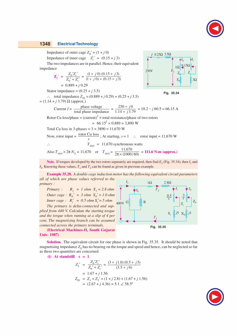
1348 Electrical Technology
Impedance of outer cage Z0′ = (1 + j 0)
Impedance of inner cage Zi′ = (0.15 + j 3)
The two impedances are in parallel. Hence, their equivalent
impedance
Z2′ = 0
0
′ ′′ + ′
i
i
Z Z
Z Z =
(1 0) (0.15 3)
(1 0) (0.15 3)
+ ++ + +
j j
j j
= 0.889 + j 0.29
Stator impedance = (0.25 + j 3.5)
∴ total impedance Z01 = (0.889 + j 0.29) + (0.25 + j 3.5)
= (1.14 + j 3.79) Ω (approx.)
Current I = phase voltage
total phase impedance =
250 0
1.14 3.79
++
j
j = 18.2 − j 60.5 = 66.15 A
Rotor Cu loss/phase = (current)2 × total resistance/phase of two rotors
= 66.152 × 0.889 = 3,890 W
Total Cu loss in 3-phases = 3 × 3890 = 11,670 W
Now, rotor input = rotor Cu loss
s; At starting, s = 1 ∴ rotor input = 11,670 W
∴ Tstart = 11,670 synchronous watts
Also Tstart × 2π NS = 11,670 or Tstart = 11,670
2 (1000 / 60)π × = 111.6 N-m (approx.)
Note. If torques developed by the two rotors separately are required, then find E2 (Fig. 35.34), then I1 and
I2. Knowing these values, T1 and T2 can be found as given in previous example.
Example 35.28. A double-cage induction motor has the following equivalent circuit parameters
all of which are phase values referred to the
primary :
Primary : R1 = 1 ohm X1 = 2.8 ohm
Outer cage : R0′ = 3 ohm X0′ = 1.0 ohm
Inner cage : Ri′ = 0.5 ohm Xi′= 5 ohm
The primary is delta-connected and sup-
plied from 440 V. Calculate the starting torque
and the torque when running at a slip of 4 per
cent. The magnetizing branch can be assumed
connected across the primary terminals.
(Electrical Machines-II, South Gujarat
Univ. 1987)
Solution. The equivalent circuit for one phase is shown in Fig. 35.35. It should be noted that
magnetising impedance Z0 has no bearing on the torque and speed and hence, can be neglected so far
as these two quantities are concerned
(i) At standstill s = 1
Z2′ = 0
0
′ ′′ + ′
i
i
Z Z
Z Z =
(3 1.0) (0.5 5)
(3.5 6)
+ ++
j j
j
= 1.67 + j 1.56
Z01 = Z1 + Z2′ = (1 + j 2.8) + (1.67 + j 1.56)
= (2.67 + j 4.36) = 5.1 ∠ 58.5º
Fig. 35.34
Fig. 35.35
Computations and Circle Diagrams 1349
Voltage per phase, V1 = 440 V. Since stator is delta-connected.
I2′′′′′ = V1/Z01 = 440/5.1 ∠ 58.5º = 86.27 ∠ − 58.5º
Combined resistance R2 = 1.6 Ω∴ starting torque per phase = I2′
2 R2 = 86.27
2 × 1.67 = 12,430 synch. watt.
(ii) when s = 0.04
Z0′′′′′ = (3/0.04) + j 1.0 = 75 + j 1.0; Zi′′′′′ = ( 0.5/0.04) + j 5 = 12.5 + j 5
Z2′′′′′ = 0
0
′ ′′ + ′
i
i
Z Z
Z Z =
(75 1.0) (12.5 5)
(87.5 6)
+ ++
j j
j = 10.3 + j 3.67
Z01 = Z1 + Z2′ = (1 + j 2.8) + (10.3 + j 6.47) = 11.3 + j 6.47 = 13.03 ∠ 29.8º
I2′′′′′ = V1/Z01 = 440/13.03 ∠ 29.8º = 33.76 ∠ − 29.8º
combined resistance R2 = 10.3 Ω∴ full-load torque per phase = I2′ R2 = 33.76
2 × 10.3 = 11.740 synch. watts
Obviously, starting torque is higher than full-load torque.
Tutorial Problems 35.4
1. Calculate the steps in a 5-section rotor starter of a 3-phase induction motor for which the starting
current should not exceed the full-load current, the full-load slip is 0.018 and the rotor resistance is
0.015 Ω per phase
ρ1 = 0.46 ΩΩΩΩΩ ; ρ2 = 0.206 ΩΩΩΩΩ ; ρ3 = 0.092 ΩΩΩΩΩ ; ρ4 = 0.042 ΩΩΩΩΩ ; ρ5 = 0.0185 ΩΩΩΩΩ(Electrical Machinery-III, Kerala Univ. Apr. 1976)
2. The full-load slip of a 3-phase double-cage induction motor is 6% and the two cages have impedances
of (3.5 + j 1.5) Ω and (0.6 + j 7.0) Ω respectively. Neglecting stator impedances and magnetising
current, calculate the starting torque in terms of full-load torque. [79%]
3. In a double-cage induction motor, if the outer cage has an impedance at standstill of (2 + j 2) ohm
and the inner cage an impedance of (0.5 + j 5) Ω, determine the slip at which the two cages develop
equal torques. [17.7%]
4. The two independent cages of a rotor have the respective standstill impedance of (3 + j 1) ohm and
(1 + j 4) ohm. What proportion of the total torque is due to the outer cage (a) at starting and (b) at a
fractional slip of 0.05 ?[(a) 83.6% (b) 25.8%] (Principle of Elect. Engg.I, Jadavpur Univ. 1975)
5. An induction motor has a double cage rotor with equivalent impedance at standstill of (1.0 + j 1.0)
and (0.2 + j 4.0) ohm. Find the relative value of torque given by each cage at a slip of 5%.
[(a) 40.1 (b) 0.4 : 1] (Electrical Machines-I, Gwalior Univ. Nov. 1977)
35.18. Speed Control of Induction Motors*
A 3-phase induction motor is practically a constant-speed machine, more or less like a d.c. shuntmotor. The speed regulation of an induction motor (having low resistance) is usually less than 5% atfull-load. However, there is one difference of practical importance between the two. Whereas d.c.
shunt motors can be made to run at any speed within wide limits, with good efficiency and speed
regulation, merely by manipulating a simple field rheostat, the same is not possible with induction
motors. In their case, speed reduction is accompanied by a corresponding loss of efficiency and good
speed regulation. That is why it is much easier to build a good adjustable-speed d.c. shunt motor than
an adjustable speed induction motor.
Different methods by which speed control of induction motors is achieved, may be grouped
under two main headings :
* For Electronic Control of AC Motors, please consult the relevant chapter of this book, in vol. III.

1350 Electrical Technology
1. Control from stator side
(a) by changing the applied voltage (b) by changing the applied frequency
(c) by changing the number of stator poles
2. Control from rotor side
(d) rotor rheostat control
(e) by operating two motors in concatenation or cascade
(f) by injecting an e.m.f. in the rotor circuit.
A brief description of these methods would be given below :
(a) Changing Applied Voltage
This method, though the cheapest and the easiest, is rarely used because
(i) a large change in voltage is required for a relatively small change in speed
(ii) this large change in voltage will result in a large change in the flux density thereby seriously
disturbing the magnetic conditions of the motor.
(b) Changing the Applied Frequency
This method is also used very rarely. We have seen that the synchronous speed of an induction
motor is given by Ns = 120 f/P. Clearly, the synchronous speed (and hence the running speed) of an
induction motor can be changed by changing the supply frequency f. However, this method could
only be used in cases where the induction motor happens to be the only load on the generators, in
which case, the supply frequency could be controlled by controlling the speed of the prime movers of
the generators. But, here again the range over which the motor speed may be varied is limited by the
economical speeds of the prime movers. This method has been used to some extent on electrically-
driven ships.
(c) Changing the Number of Stator Poles
This method is easily applicable to squirrel-cage motors because the squirrel-cage rotor adopts
itself to any reasonable number of stator poles.
From the above equation it is also clear that the synchronous (and hence the running)speed of an
induction motor could also be changed by changing the number of stator poles. This change of
number of poles is achieved by having two or more entirely independent stator windings in the same
slots. Each winding gives a different number of poles and hence different synchronous speed. For
example, a 36-slot stator may have two 3-φ windings, one with 4 poles and the other with 6-poles.
With a supply frequency of 50-Hz, 4-pole winding will give Ns = 120 × 50/4 = 1500 r.p.m. and the 6-
pole winding will give Ns = 120 × 50/6 = 1000 r.p.m. Motors with four independent stator winding are
also in use and they give four different synchronous (and hence running) speeds. Of course, one
winding is used at a time, the others being entirely disconnected.
This method has been used for elevator motors, traction motors and also for small motors driving
machine tools.
Speeds in the ratio of 2:1 can be produced by a single winding if wound on the consequent-pole
principle. In that case, each of the two stator windings can be connected by a simple switch to give
two speeds, each, which means four speeds in all. For example, one stator winding may give 4 or
8-poles and the other 6 or 12-poles. For a supply frequency of 50-Hz, the four speeds will be 1500,
750, 1000 and 500 r.p.m. Another combination, commonly used, is to group 2- and 4-pole winding
with a 6- and 12-pole winding, which gives four synchronous speeds of 3000, 1500, 1000 and 500
r.p.m.
(d) Rotor Rheostat Control
In this method (Fig. 35.36), which is applicable to slip-ring motors alone, the motor speed is
reduced by introducing an external resistance in the rotor circuit. For this purpose, the rotor starter

Computations and Circle Diagrams 1351
may be used, provided it is continuously rated. This method is, in fact, similar to the armature
rheostat control method of d.c. shunt motors.
It has beenshown in Art34.22 that nears y n c h r o n o u sspeed (i.e. for verysmall slip value),T ∝ s/R2.
It is obviousthat for a giventorque, slip can beincreased i.e.speed can bedecreased by increasing the rotor resistance R2.
One serious disadvantage of this method is that with increase in rotor resistance, I2R losses also
increase which decrease the operating efficiency of the motor. In fact, the loss is directly proportionalto the reduction in the speed.
The second disadvantage is the double dependence of speed, not only on R2 but on load as well.
Because of the wastefulness of this method, it is used where speed changes are needed for short
periods only.
Example 35.29. The rotor of a 4-pole, 50-Hz slip-ring induction motor has a resistance of 0.30
Ω per phase and runs at 1440 rpm. at full load. Calculate the external resistance per phase which
must be added to lower the speed to 1320 rpm, the torque being the same as before.
(Advanced Elect. Machines AMIE Sec.E1992)
Solution. The motor torque is given by T = 22 2
2 2( )
K s R
R s X+
Since,X 2 is not given,T = 22
22
K s R K s
RR=
In the first case, T1 = Ks1/R2; in the second case, T2 = Ks2 / (R2 + r)
where r is the external resistance per phase, added to the rotor circuit
Since T1 = T2 ∴ K s1/R2 = K s2 / (R2 + r) or (R2 + r) / R2 = s2 / s1
Now, Ns = 120 × 50/4 = 1500 rpm; N1 = 1440 rpm; N2 = 1320 rpm
∴s1 = (1500 − 1440)/1500 = 0.04; s2 = (1500 − 1320)/1500 = 0.12
∴ 0.3 0.12
0.3 0.04
r+ = ∴ r = 0.6 ΩΩΩΩΩ
Example 35.30. A certain 3-phase, 6-pole, 50-Hz induction motor when fully-loaded, runs with
a slip of 3%. Find the value of the resistance necessary in series per phase of the rotor to reduce the
speed by 10%. Assume that the resistance of the rotor per phase is 0.2 ohm.
(Electrical Engineering-II (M), Bangalore Univ. 1989)
Solution. T = 222 2 2
22 2 2( )
sK RK s R K s
RR s X R= =
+- neglecting (s X 2)
∴ T1 = Ks1 / R2 and T2 = K s2 / (R2 + r) where r is the external resistance per phase added to the
rotor circuit.
Since T1 = T2, K s1 / R2 = K s2 / (R2 + r) or (R2 + r)/R2 = s2 / s1
Now, Ns = 120 × 50/6 = 1000 rpm., s1 = 0.03, N1 = 1000 (1 − 0.030) = 970 rpm.
Fig. 35. 36
Stator
Rotor
CollectorRings
3-PhaseSupply
Starting Rheostat& Speed Controller
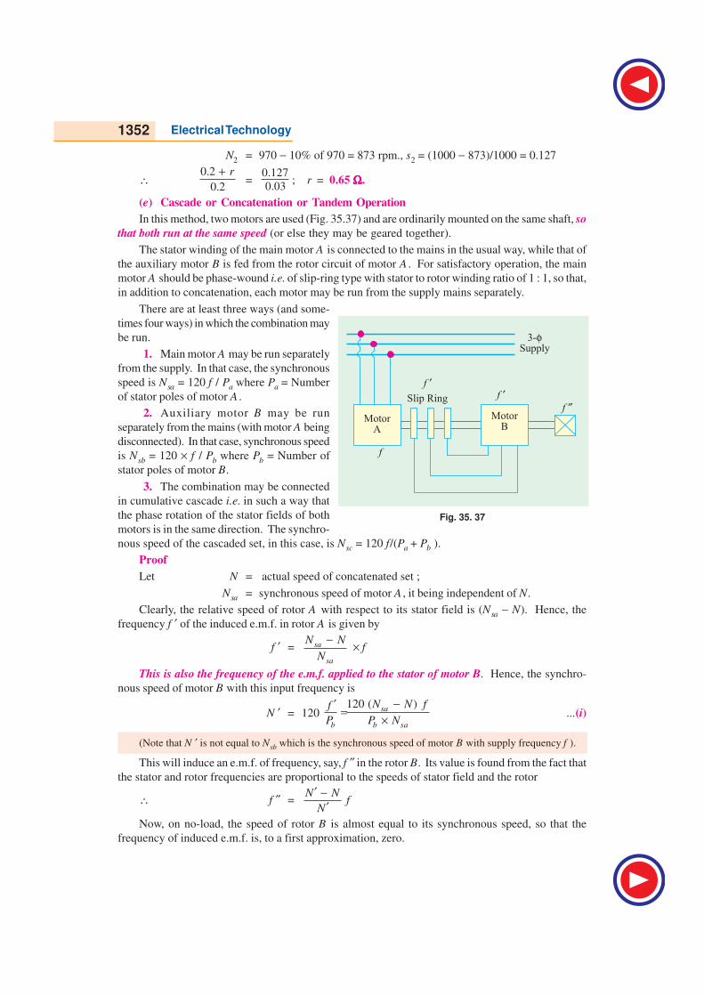
1352 Electrical Technology
N2 = 970 − 10% of 970 = 873 rpm., s2 = (1000 − 873)/1000 = 0.127
∴0.2
0.2
r+=
0.127
0.03; r = 0.65 ΩΩΩΩΩ.
(e) Cascade or Concatenation or Tandem Operation
In this method, two motors are used (Fig. 35.37) and are ordinarily mounted on the same shaft, so
that both run at the same speed (or else they may be geared together).
The stator winding of the main motor A is connected to the mains in the usual way, while that of
the auxiliary motor B is fed from the rotor circuit of motor A . For satisfactory operation, the main
motor A should be phase-wound i.e. of slip-ring type with stator to rotor winding ratio of 1 : 1, so that,
in addition to concatenation, each motor may be run from the supply mains separately.
There are at least three ways (and some-
times four ways) in which the combination may
be run.
1. Main motor A may be run separately
from the supply. In that case, the synchronous
speed is Nsa = 120 f / Pa where Pa = Number
of stator poles of motor A .
2. Auxiliary motor B may be run
separately from the mains (with motor A being
disconnected). In that case, synchronous speed
is Nsb = 120 × f / Pb where Pb = Number of
stator poles of motor B.
3. The combination may be connected
in cumulative cascade i.e. in such a way that
the phase rotation of the stator fields of both
motors is in the same direction. The synchro-
nous speed of the cascaded set, in this case, is Nsc = 120 f/(Pa + Pb ).
Proof
Let N = actual speed of concatenated set ;
Nsa = synchronous speed of motor A , it being independent of N.
Clearly, the relative speed of rotor A with respect to its stator field is (Nsa − N). Hence, the
frequency f ′ of the induced e.m.f. in rotor A is given by
f ′ = sa
sa
N N
N
− × f
This is also the frequency of the e.m.f. applied to the stator of motor B. Hence, the synchro-
nous speed of motor B with this input frequency is
N ′ = 120 120 ( )
sa
b b sa
N N ff
P P N
−′=
×...(i)
(Note that N ′ is not equal to Nsb which is the synchronous speed of motor B with supply frequency f ).
This will induce an e.m.f. of frequency, say, f ″ in the rotor B. Its value is found from the fact that
the stator and rotor frequencies are proportional to the speeds of stator field and the rotor
∴ f ″ =N N
N
′ −′
f
Now, on no-load, the speed of rotor B is almost equal to its synchronous speed, so that the
frequency of induced e.m.f. is, to a first approximation, zero.
Fig. 35. 37
Computations and Circle Diagrams 1353
f ″ = 0, or N N
N
′ −′
f = 0 or N′ = N ...(ii)
From (i) above N ′ =120 ( ) 120
1sa
b sa b sa
f N N f N
P N P N
− = − × Hence, from (ii) above,
1201
b sa
f N
P N −
= N or120120 1
1 + ×= sa bb
ffN
N PP
Putting Nsa = 120 f/Pa, we get
120
b
f
P= N
1201 1
120a a
b b
P PfN
f P P
+ × = +
∴ N = 120
( )a b
f
P P+
Concatenated speed of the set = 120 f / (Pa + Pb )
How the Set Starts ?
When the cascaded set is started, the voltage at frequency f is applied to the stator winding of
machine A . An induced e.m.f. of the same frequency is produced in rotor A which is supplied to
auxiliary motor B. Both the motors develop a forward torque. As the shaft speed rises, the rotor
frequency of motor A falls and so does the synchronous speed of motor B. The set settles down to a
stable speed when the shaft speed becomes equal to the speed of rotating field of motor B.
Considering load conditions, we find that the electrical power taken in by stator A is partly used
to meet its I2R and core losses and the rest is given to its rotor. The power given to rotor is further
divided into two parts : one part, proportional to the speed of set i.e. N is converted into mechanical
power and the other part proportional to (Nsa − N) is developed as electrical power at the slip frequency,
and is passed on to the auxliary motor B, which uses it for producing mechanical power and losses.
Hence, approximately, the mechanical outputs of the two motors are in the ratio N : (Nsa − N). In fact,
it comes to that the mechanical outputs are in the ratio of the number of poles of the motors.
It may be of interest to the reader to know that it can be proved that
(i) s = f ′′ / f where s = slip of the set referred to its synchronous speed Nsc.
= (Nsc − N) / Nsc
(ii) s = sa sb
where sa and sb are slips of two motors, referred to their respective stators i.e
sa =sa
sa
N N
N
−and sb =
N N
N
′ −
Conclusion
We can briefly note the main conclusions drawn from the above discussion :
(a) the mechanical outputs of the two motors are in the ratio of their number of poles.
(b) s = f ″/ f (c) s = sa.sb
4. The fourth possible connection is the differential cascade. In this method, the phase rotation
of stator field of the motor B is opposite to that of the stator of motor A . This reversal of
phase rotation of stator of motor B is obtained by interchanging any of its two leads. It can
be proved in the same way as above, that for this method of connection, the synchronous
speed of the set is
Nsc = 120 f / (Pa − Pb )
As the differentially-cascaded set has a very small or zero starting torque, this method is rarely
used. Moreover, the above expression for synchronous speed becomes meaningless for Pa = Pb.
Example 35.31. Two 50-Hz, 3-φ induction motors having six and four poles respectively are
cumulatively cascaded, the 6-pole motor being connected to the main supply. Determine the

1354 Electrical Technology
frequencies of the rotor currents and the slips referred to each stator field if the set has a slip of 2 per
cent. (Elect. Machinery-II Madras Univ. 1987)
Solution. Synchronous speed of set Nsc = 120 × 50/10 = 600 r.p.m.
Actual rotor speed N = (1 − s) Nsc = (1 − 0.02) 600 = 588 r.p.m.
Synchronous speed of the stator field of 6-pole motor, Nsa = 120 × 50/6 = 1000 r.p.m.Slip referred to this stator field is
sa =1000 588
1000sa
sa
N N
N
− −= = 0.412 or 41.2%
Frequency of the rotor currents of 6-pole motor f ′ = sa f = 0.412 × 50 = 20.6 Hz
This is also the frequency of stator currents of the four pole motor. The synchronous speed of the
stator of 4-pole motor is
N ′ = 120 × 20.6/4 = 618 r.p.m.
This slip, as referred to the 4-pole motor, is sb =618 588
618
N N
N
′ − −=′
= 0.0485 or 4.85 %
The frequency of rotor current of 4-pole motor is
f ″ = sb f ′ = 0.0485 × 20.6 = 1.0 Hz (approx)
As a check, f ″ = sf = 0.02 × 50 = 1.0 Hz
Example 35.32. A 4-pole induction motor and a 6-pole induction motor are connected in
cumulative cascade. The frequency in the secondary circuit of the 6-pole motor is observed to be 1.0
Hz. Determine the slip in each machine and the combined speed of the set. Take supply frequency as
50 Hz. (Electrical Machinery-II, Madras Univ. 1986)
Solution. With reference to Art. 35.18 (e) and Fig. 35.38
Nsc = 120 × 50/(4 + 6) = 600 r.p.m.
s = f ″/f = 1/50 = 0.02
N = actual speed of the concatenated set
∴ 0.02 =600
600
N−or N = 588 r.p.m.
Nsa = 120 × 50/ 4 = 1500 r.p.m.
sa = (1500 − 588)/1500
= 0.608 or 60.8%
f ′ = sa f = 0.608 × 50 = 30.4 Hz
N ′ = synchronous speed of 6-pole motor
with frequency f ′= 120 × 30.4/6 = 608 r.p.m.
sb =608 588
608
N N
N
′ − −=′
= 0.033 or 3.3%
Example 35.33. The stator of a 6-pole motor is joined to a 50-Hz supply and the machine is
mechanically coupled and joined in cascade with a 4-pole motor, Neglecting all losses, determine
the speed and output of the 4-pole motor when the total load on the combination is 74.6 kW.
Solution. As all losses are neglected, the actual speed of the rotor is assumed to be equal to the
synchronous speed of the set.
Now, Nsc = 120 × 50/10 = 600 r.p.m.
Fig. 35.38
MotorA
MotorB
Slip Ring
3-Supply
f
f f
f
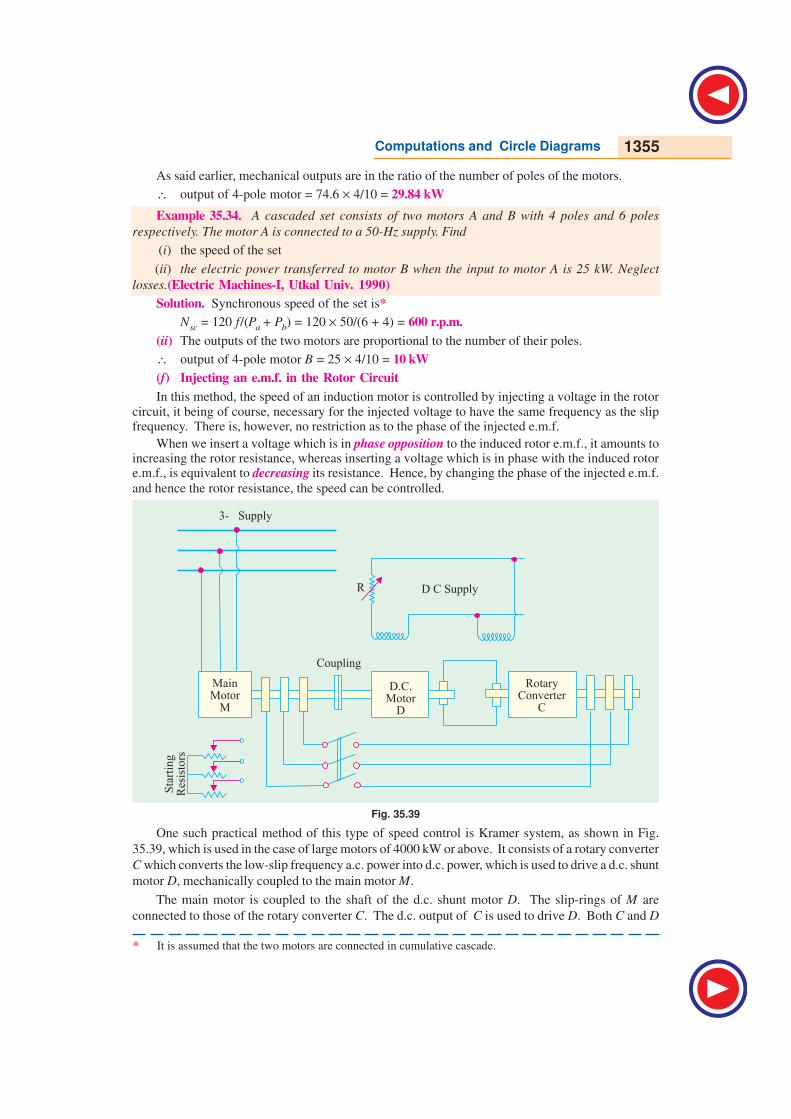
Computations and Circle Diagrams 1355
MainMotor
M
3- Supply
Sta
rtin
gR
esis
tors
D C Supply
Coupling
D.C.Motor
D
RotaryConverter
C
R
As said earlier, mechanical outputs are in the ratio of the number of poles of the motors.
∴ output of 4-pole motor = 74.6 × 4/10 = 29.84 kW
Example 35.34. A cascaded set consists of two motors A and B with 4 poles and 6 poles
respectively. The motor A is connected to a 50-Hz supply. Find
(i) the speed of the set
(ii) the electric power transferred to motor B when the input to motor A is 25 kW. Neglect
losses.(Electric Machines-I, Utkal Univ. 1990)
Solution. Synchronous speed of the set is*
Nsc = 120 f/(Pa + Pb) = 120 × 50/(6 + 4) = 600 r.p.m.
(ii) The outputs of the two motors are proportional to the number of their poles.
∴ output of 4-pole motor B = 25 × 4/10 = 10 kW
(f) Injecting an e.m.f. in the Rotor Circuit
In this method, the speed of an induction motor is controlled by injecting a voltage in the rotorcircuit, it being of course, necessary for the injected voltage to have the same frequency as the slipfrequency. There is, however, no restriction as to the phase of the injected e.m.f.
When we insert a voltage which is in phase opposition to the induced rotor e.m.f., it amounts toincreasing the rotor resistance, whereas inserting a voltage which is in phase with the induced rotore.m.f., is equivalent to decreasing its resistance. Hence, by changing the phase of the injected e.m.f.
and hence the rotor resistance, the speed can be controlled.
Fig. 35.39
One such practical method of this type of speed control is Kramer system, as shown in Fig.
35.39, which is used in the case of large motors of 4000 kW or above. It consists of a rotary converter
C which converts the low-slip frequency a.c. power into d.c. power, which is used to drive a d.c. shunt
motor D, mechanically coupled to the main motor M.
The main motor is coupled to the shaft of the d.c. shunt motor D. The slip-rings of M are
connected to those of the rotary converter C. The d.c. output of C is used to drive D. Both C and D
* It is assumed that the two motors are connected in cumulative cascade.
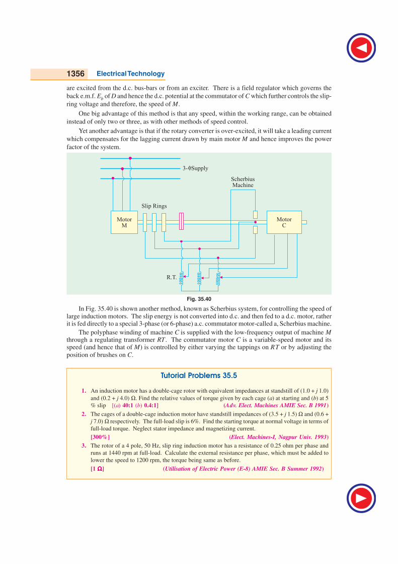
1356 Electrical Technology
are excited from the d.c. bus-bars or from an exciter. There is a field regulator which governs the
back e.m.f. Eb of D and hence the d.c. potential at the commutator of C which further controls the slip-
ring voltage and therefore, the speed of M.
One big advantage of this method is that any speed, within the working range, can be obtained
instead of only two or three, as with other methods of speed control.
Yet another advantage is that if the rotary converter is over-excited, it will take a leading current
which compensates for the lagging current drawn by main motor M and hence improves the power
factor of the system.
Fig. 35.40
In Fig. 35.40 is shown another method, known as Scherbius system, for controlling the speed oflarge induction motors. The slip energy is not converted into d.c. and then fed to a d.c. motor, ratherit is fed directly to a special 3-phase (or 6-phase) a.c. commutator motor-called a, Scherbius machine.
The polyphase winding of machine C is supplied with the low-frequency output of machine Mthrough a regulating transformer RT. The commutator motor C is a variable-speed motor and itsspeed (and hence that of M) is controlled by either varying the tappings on RT or by adjusting the
position of brushes on C.
Tutorial Problems 35.5
1. An induction motor has a double-cage rotor with equivalent impedances at standstill of (1.0 + j 1.0)
and (0.2 + j 4.0) Ω. Find the relative values of torque given by each cage (a) at starting and (b) at 5
% slip [(a) 40:1 (b) 0.4:1] (Adv. Elect. Machines AMIE Sec. B 1991)
2. The cages of a double-cage induction motor have standstill impedances of (3.5 + j 1.5) Ω and (0.6 +
j 7.0) Ω respectively. The full-load slip is 6%. Find the starting torque at normal voltage in terms of
full-load torque. Neglect stator impedance and magnetizing current.
[300%] (Elect. Machines-I, Nagpur Univ. 1993)
3. The rotor of a 4 pole, 50 Hz, slip ring induction motor has a resistance of 0.25 ohm per phase and
runs at 1440 rpm at full-load. Calculate the external resistance per phase, which must be added to
lower the speed to 1200 rpm, the torque being same as before.
[1 ΩΩΩΩΩ] (Utilisation of Electric Power (E-8) AMIE Sec. B Summer 1992)
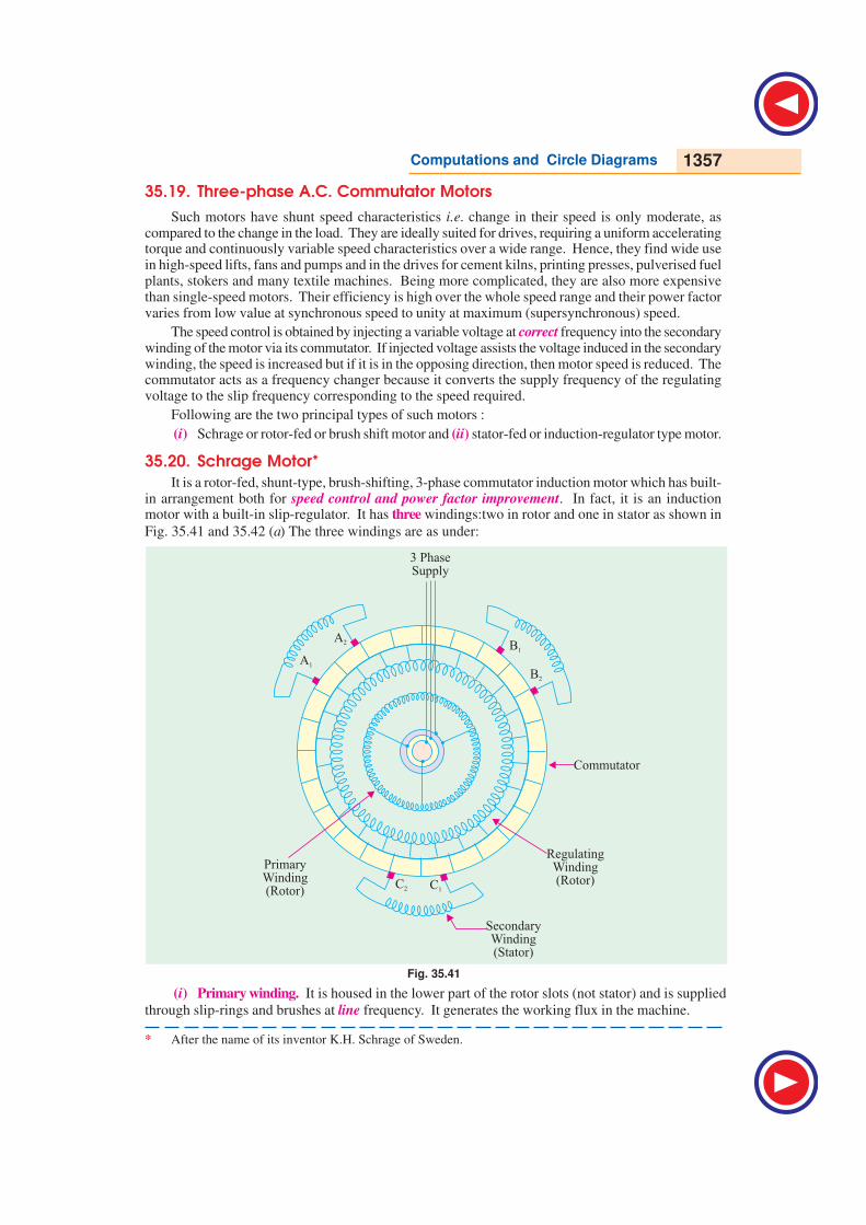
Computations and Circle Diagrams 1357
3 PhaseSupply
A2
B2
C2 C1
B1
A1
PrimaryWinding(Rotor)
RegulatingWinding(Rotor)
SecondaryWinding(Stator)
Commutator
35.19. Three-phase A.C. Commutator Motors
Such motors have shunt speed characteristics i.e. change in their speed is only moderate, ascompared to the change in the load. They are ideally suited for drives, requiring a uniform acceleratingtorque and continuously variable speed characteristics over a wide range. Hence, they find wide usein high-speed lifts, fans and pumps and in the drives for cement kilns, printing presses, pulverised fuelplants, stokers and many textile machines. Being more complicated, they are also more expensivethan single-speed motors. Their efficiency is high over the whole speed range and their power factorvaries from low value at synchronous speed to unity at maximum (supersynchronous) speed.
The speed control is obtained by injecting a variable voltage at correct frequency into the secondarywinding of the motor via its commutator. If injected voltage assists the voltage induced in the secondarywinding, the speed is increased but if it is in the opposing direction, then motor speed is reduced. Thecommutator acts as a frequency changer because it converts the supply frequency of the regulatingvoltage to the slip frequency corresponding to the speed required.
Following are the two principal types of such motors :
(i) Schrage or rotor-fed or brush shift motor and (ii) stator-fed or induction-regulator type motor.
35.20. Schrage Motor*
It is a rotor-fed, shunt-type, brush-shifting, 3-phase commutator induction motor which has built-in arrangement both for speed control and power factor improvement. In fact, it is an inductionmotor with a built-in slip-regulator. It has three windings:two in rotor and one in stator as shown in
Fig. 35.41 and 35.42 (a) The three windings are as under:
* After the name of its inventor K.H. Schrage of Sweden.
Fig. 35.41
(i) Primary winding. It is housed in the lower part of the rotor slots (not stator) and is supplied
through slip-rings and brushes at line frequency. It generates the working flux in the machine.
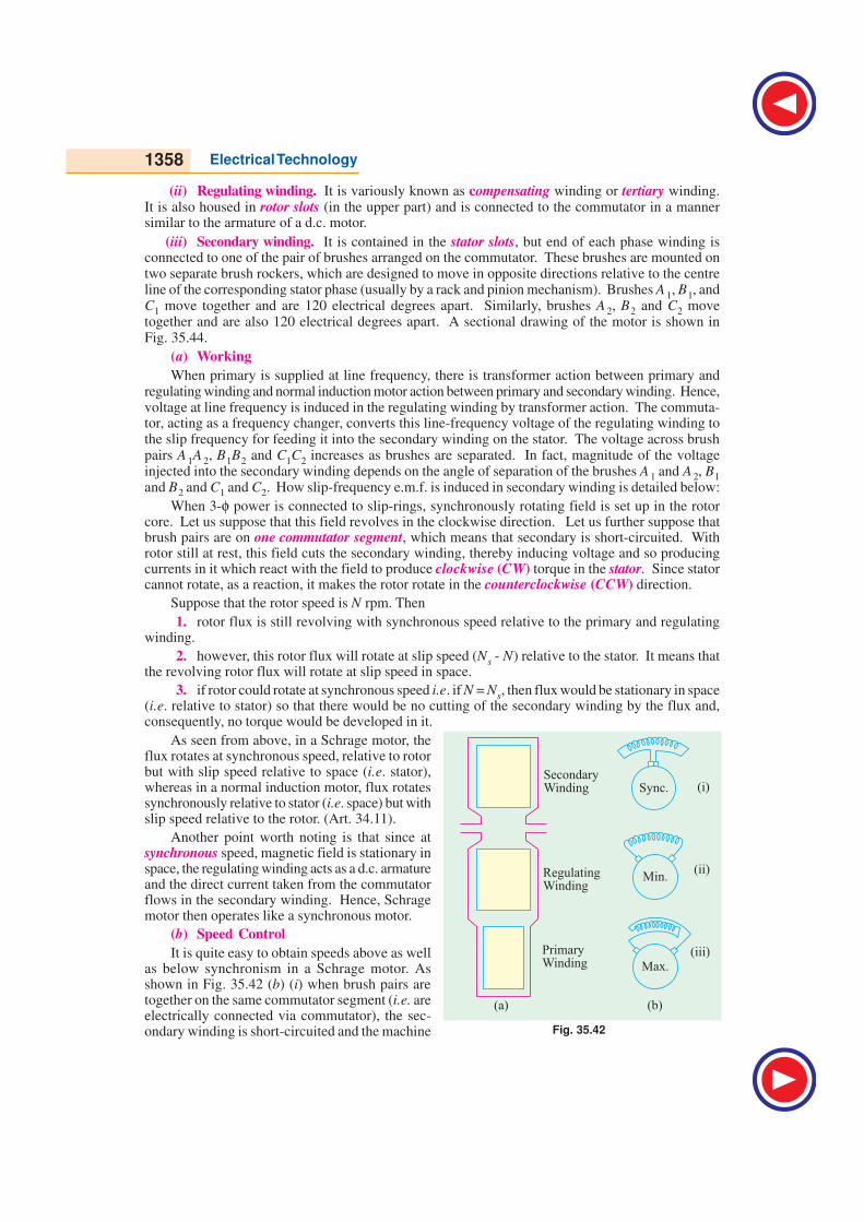
1358 Electrical Technology
(ii) Regulating winding. It is variously known as compensating winding or tertiary winding.It is also housed in rotor slots (in the upper part) and is connected to the commutator in a mannersimilar to the armature of a d.c. motor.
(iii) Secondary winding. It is contained in the stator slots, but end of each phase winding isconnected to one of the pair of brushes arranged on the commutator. These brushes are mounted ontwo separate brush rockers, which are designed to move in opposite directions relative to the centreline of the corresponding stator phase (usually by a rack and pinion mechanism). Brushes A 1, B1, andC1 move together and are 120 electrical degrees apart. Similarly, brushes A 2, B2 and C2 movetogether and are also 120 electrical degrees apart. A sectional drawing of the motor is shown inFig. 35.44.
(a) Working
When primary is supplied at line frequency, there is transformer action between primary andregulating winding and normal induction motor action between primary and secondary winding. Hence,voltage at line frequency is induced in the regulating winding by transformer action. The commuta-tor, acting as a frequency changer, converts this line-frequency voltage of the regulating winding tothe slip frequency for feeding it into the secondary winding on the stator. The voltage across brushpairs A 1A 2, B1B2 and C1C2 increases as brushes are separated. In fact, magnitude of the voltageinjected into the secondary winding depends on the angle of separation of the brushes A 1 and A 2, B1
and B2 and C1 and C2. How slip-frequency e.m.f. is induced in secondary winding is detailed below:
When 3-φ power is connected to slip-rings, synchronously rotating field is set up in the rotorcore. Let us suppose that this field revolves in the clockwise direction. Let us further suppose thatbrush pairs are on one commutator segment, which means that secondary is short-circuited. Withrotor still at rest, this field cuts the secondary winding, thereby inducing voltage and so producingcurrents in it which react with the field to produce clockwise (CW) torque in the stator. Since statorcannot rotate, as a reaction, it makes the rotor rotate in the counterclockwise (CCW) direction.
Suppose that the rotor speed is N rpm. Then
1. rotor flux is still revolving with synchronous speed relative to the primary and regulatingwinding.
2. however, this rotor flux will rotate at slip speed (Ns - N) relative to the stator. It means thatthe revolving rotor flux will rotate at slip speed in space.
3. if rotor could rotate at synchronous speed i.e. if N = Ns, then flux would be stationary in space(i.e. relative to stator) so that there would be no cutting of the secondary winding by the flux and,consequently, no torque would be developed in it.
As seen from above, in a Schrage motor, theflux rotates at synchronous speed, relative to rotorbut with slip speed relative to space (i.e. stator),whereas in a normal induction motor, flux rotatessynchronously relative to stator (i.e. space) but withslip speed relative to the rotor. (Art. 34.11).
Another point worth noting is that since atsynchronous speed, magnetic field is stationary inspace, the regulating winding acts as a d.c. armatureand the direct current taken from the commutatorflows in the secondary winding. Hence, Schragemotor then operates like a synchronous motor.
(b) Speed Control
It is quite easy to obtain speeds above as wellas below synchronism in a Schrage motor. Asshown in Fig. 35.42 (b) (i) when brush pairs aretogether on the same commutator segment (i.e. areelectrically connected via commutator), the sec-ondary winding is short-circuited and the machine Fig. 35.42
Sync.
Min.
Max.
PrimaryWinding
RegulatingWinding
SecondaryWinding (i)
(ii)
(iii)
(a) (b)
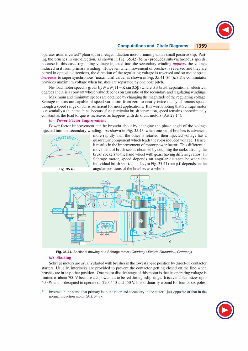
Computations and Circle Diagrams 1359
Fig. 35.43
operates as an inverted* plain squirrel-cage induction motor, running with a small positive slip. Part-ing the brushes in one direction, as shown in Fig. 35.42 (b) (ii) produces subsynchronous speeds,because in this case, regulating voltage injected into the secondary winding opposes the voltageinduced in it from primary winding. However, when movement of brushes is reversed and they areparted in opposite directions, the direction of the regulating voltage is reversed and so motor speedincreases to super synchronous (maximum) value, as shown in Fig. 35.41 (b) (iii) The commutatorprovides maximum voltage when brushes are separated by one pole pitch.
No-load motor speed is given by N ≅ Ns (1 − K sin 0.5β) where β is brush separation in electricaldegrees and K is a constant whose value depends on turn ratio of the secondary and regulating windings.
Maximum and minimum speeds are obtained by changing the magnitude of the regulating voltage.Schrage motors are capable of speed variations from zero to nearly twice the synchronous speed,though a speed range of 3:1 is sufficient for most applications. It is worth noting that Schrage motoris essentially a shunt machine, because for a particular brush separation, speed remains approximatelyconstant as the load torque is increased as happens with dc shunt motors (Art 29.14).
(c) Power Factor Improvement
Power factor improvement can be brought about by changing the phase angle of the voltageinjected into the secondary winding. As shown in Fig. 35.43, when one set of brushes is advanced
more rapidly than the other is retarted, then injected voltage has aquadrature component which leads the rotor induced voltage. Hence,it results in the improvement of motor power factor. This differentialmovement of brush sets is obtained by coupling the racks driving thebrush rockers to the hand wheel with gears having differing ratios. InSchrage motor, speed depends on angular distance between theindividual brush sets (A 1 and A 2 in Fig. 35.41) but p.f. depends on the
angular positions of the brushes as a whole.
Fig. 35.44. Sectional drawing of a Schrage motor (Courtesy : Elekrta Faurandou, Germany)
(d) Starting
Schrage motors are usually started with brushes in the lowest speed position by direct-on contactor
starters. Usually, interlocks are provided to prevent the contactor getting closed on the line when
brushes are in any other position. One major disadvantage of this motor is that its operating voltage is
limited to about 700 V because a.c. power has to be fed through slip-rings. It is available in sizes upto
40 kW and is designed to operate on 220, 440 and 550 V. It is ordinarily wound for four or six poles.
* Inverted in the sense that primary is in the rotor and secondary in the stator - just opposite of that in the
normal induction motor (Art. 34.3).
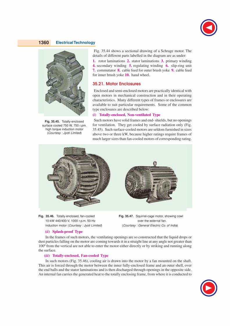
1360 Electrical Technology
Fig. 35.44 shows a sectional drawing of a Schrage motor. The
details of different parts labelled in the diagram are as under:
1. rotor laminations 2. stator laminations 3. primary winding
4. secondary winding 5. regulating winding 6. slip-ring unit
7. commutator 8. cable feed for outer brush yoke 9. cable feed
for inner brush yoke 10. hand wheel.
35.21. Motor Enclosures
Enclosed and semi-enclosed motors are practically identical with
open motors in mechanical construction and in their operating
characteristics. Many different types of frames or enclosures are
available to suit particular requirements. Some of the common
type enclosures are described below:
(i) Totally-enclosed, Non-ventilated Type
Such motors have solid frames and end- shields, but no openings
for ventilation. They get cooled by surface radiation only (Fig.
35.45). Such surface-cooled motors are seldom furnished in sizes
above two or three kW, because higher ratings require frames of
much larger sizes than fan-cooled motors of corresponding rating.
Fig. 35.46. Totally-enclosed, fan-cooled Fig. 35.47. Squirrel-cage motor, showing cowl
10-kW 440/400-V, 1000 r.p.m. 50-Hz over the external fan.
induction motor (Courtesy : Jyoti Limited) (Courtesy : General Electric Co. of India)
(ii) Splash-proof Type
In the frames of such motors, the ventilating openings are so constructed that the liquid drops ordust particles falling on the motor are coming towards it in a straight line at any angle not greater than
100º from the vertical are not able to enter the motor either directly or by striking and running alongthe surface.
(iii) Totally-enclosed, Fan-cooled Type
In such motors (Fig. 35.46), cooling air is drawn into the motor by a fan mounted on the shaft.
This air is forced through the motor between the inner fully-enclosed frame and an outer shell, overthe end balls and the stator laminations and is then discharged through openings in the opposite side.
An internal fan carries the generated heat to the totally enclosing frame, from where it is conducted to
Fig. 35.45. Totally-enclosed
surface cooled 750 W, 750 r.pm.
high torque induction motor
(Courtesy : Jyoti Limited)

Computations and Circle Diagrams 1361
the outside. Because of totally enclosing frame, all working parts are protected against corrosive orabrasive effects of fumes, dust, and moisture.
(iv) Cowl-covered Motor
These motors are simplified form of fan-cooled motors
(Fig. 35.47). These consist of totally-enclosed frame with afan and cowl mounted at the end opposite to the driving
end. The air is drawn into the cowl with the help of fan andis then forced over the frame. The contours of the cowl
guide the cooling air in proper directions. These motorsare superior to the usual fan-cooled motors for operation in
extremely dusty atmosphere i.e. gas works, chemical works,collieries and quarries etc. because there are no air passages
which will become clogged with dust.
(v) Protected Type
This construction consists of perforated covers for the openings in both end shields
(vi) Drip-proof Motors
The frames of such motors are so constructed that
liquid drops or dust particles, falling on the machine
at any angle greater than 15º from the vertical, cannot
enter the motor, either directly or by striking and
running along a horizontal or inwardly inclined smooth
surface (Fig. 35.51).
(vii) Self (Pipe) Ventilated Type
The construction of such motors consists of enclosed
shields with provision for pipe connection on both the
shields. The motor fan circulates sufficient air through
pipes which are of ample section.
(viii) Separately (Forced) Ventilated Type
These motors are similar to the self-ventilated type
except that ventilation is provided by a separated blower.
35.22. Standard Types of Squirrel-cage Motors
Different types of 3-phase squirrel-cage motors
have been standardized, according to their electric
characteristics, into six types, designated as design A ,
B, C, D, E and F respectively. The original commercial
squirrel-cage induction motors which were of shallow-
slot type are designated as class A . For this reason,
Class A motors are used as a reference and are referred
to as ‘normal starting-torque, normal starting-current,
normal slip’ motors.
(i) Class A - Normal starting torque, normal
starting current, normal slip
(ii) Class B - Normal starting torque, low starting
current, normal slip
(iii) Class C - High starting torque, low starting
current, normal slip
Fig. 35.48. Squirrel cage motor
Fig. 35.49. Protected slip-ring motor with totally
enclose slip -rings. (Courtesy : GeneralElectric Co. of India)
Fig. 35.50. Squirrel cage A C induction motor
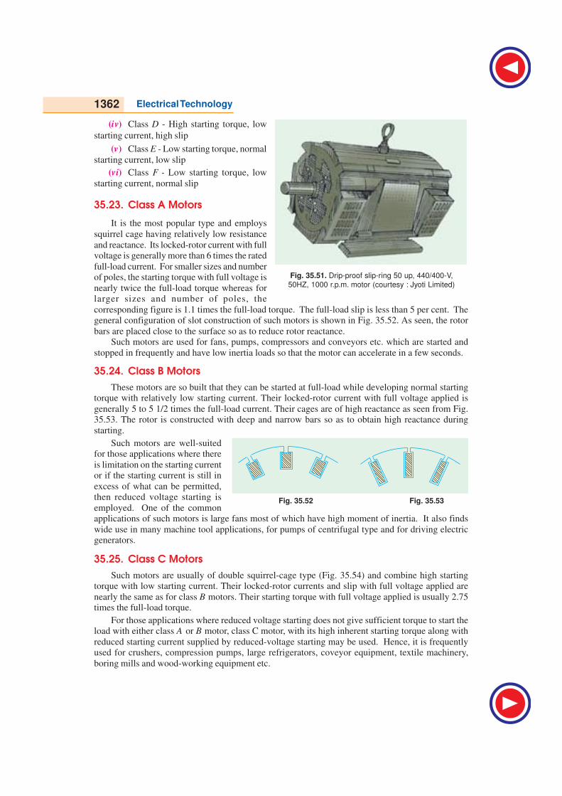
1362 Electrical Technology
(iv) Class D - High starting torque, low
starting current, high slip
(v) Class E - Low starting torque, normal
starting current, low slip
(vi) Class F - Low starting torque, low
starting current, normal slip
35.23. Class A Motors
It is the most popular type and employs
squirrel cage having relatively low resistance
and reactance. Its locked-rotor current with fullvoltage is generally more than 6 times the rated
full-load current. For smaller sizes and numberof poles, the starting torque with full voltage is
nearly twice the full-load torque whereas forlarger sizes and number of poles, the
corresponding figure is 1.1 times the full-load torque. The full-load slip is less than 5 per cent. Thegeneral configuration of slot construction of such motors is shown in Fig. 35.52. As seen, the rotor
bars are placed close to the surface so as to reduce rotor reactance.Such motors are used for fans, pumps, compressors and conveyors etc. which are started and
stopped in frequently and have low inertia loads so that the motor can accelerate in a few seconds.
35.24. Class B Motors
These motors are so built that they can be started at full-load while developing normal startingtorque with relatively low starting current. Their locked-rotor current with full voltage applied is
generally 5 to 5 1/2 times the full-load current. Their cages are of high reactance as seen from Fig.35.53. The rotor is constructed with deep and narrow bars so as to obtain high reactance during
starting.
Such motors are well-suitedfor those applications where there
is limitation on the starting currentor if the starting current is still in
excess of what can be permitted,then reduced voltage starting is
employed. One of the commonapplications of such motors is large fans most of which have high moment of inertia. It also finds
wide use in many machine tool applications, for pumps of centrifugal type and for driving electricgenerators.
35.25. Class C Motors
Such motors are usually of double squirrel-cage type (Fig. 35.54) and combine high startingtorque with low starting current. Their locked-rotor currents and slip with full voltage applied are
nearly the same as for class B motors. Their starting torque with full voltage applied is usually 2.75times the full-load torque.
For those applications where reduced voltage starting does not give sufficient torque to start theload with either class A or B motor, class C motor, with its high inherent starting torque along with
reduced starting current supplied by reduced-voltage starting may be used. Hence, it is frequentlyused for crushers, compression pumps, large refrigerators, coveyor equipment, textile machinery,
boring mills and wood-working equipment etc.
Fig. 35.52 Fig. 35.53
Fig. 35.51. Drip-proof slip-ring 50 up, 440/400-V,
50HZ, 1000 r.p.m. motor (courtesy : Jyoti Limited)
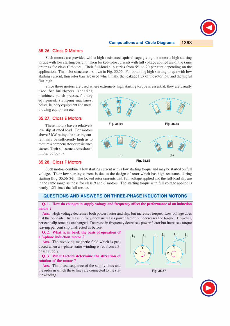
Computations and Circle Diagrams 1363
Fig. 35.57
L1L1L3
L3L2L2
R RB B
Y Y
35.26. Class D Motors
Such motors are provided with a high-resistance squirrel cage giving the motor a high starting
torque with low starting current. Their locked-rotor currents with full voltage applied are of the same
order as for class C motors. Their full-load slip varies from 5% to 20 per cent depending on the
application. Their slot structure is shown in Fig. 35.55. For obtaining high starting torque with low
starting current, thin rotor bars are used which make the leakage flux of the rotor low and the useful
flux high.
Since these motors are used where extremely high starting torque is essential, they are usually
used for bulldozers, shearing
machines, punch presses, foundry
equipment, stamping machines,
hoists, laundry equipment and metal
drawing equipment etc.
35.27. Class E Motors
These motors have a relatively
low slip at rated load. For motors
above 5 kW rating, the starting cur-
rent may be sufficiently high as to
require a compensator or resistance
starter. Their slot structure is shown
in Fig. 35.56 (a).
35.28. Class F Motors
Such motors combine a low starting current with a low starting torque and may be started on full
voltage. Their low starting current is due to the design of rotor which has high reactance during
starting [Fig. 35.56 (b)]. The locked rotor currents with full voltage applied and the full-load slip are
in the same range as those for class B and C motors. The starting torque with full voltage applied is
nearly 1.25 times the full-torque.
QUESTIONS AND ANSWERS ON THREE-PHASE INDUCTION MOTORS
Q. 1. How do changes in supply voltage and frequency affect the performance of an induction
motor ?
Ans. High voltage decreases both power factor and slip, but increases torque. Low voltage does
just the opposite. Increase in frequency increases power factor but decreases the torque. However,
per cent slip remains unchanged. Decrease in frequency decreases power factor but increases torque
leaving per cent slip unaffected as before.
Q. 2. What is, in brief, the basis of operation of
a 3-phase induction motor ?
Ans. The revolving magnetic field which is pro-
duced when a 3-phase stator winding is fed from a 3-
phase supply.
Q. 3. What factors determine the direction of
rotation of the motor ?
Ans. The phase sequence of the supply lines and
the order in which these lines are connected to the sta-
tor winding.
Fig. 35.54 Fig. 35.55
Fig. 35.56
( )a ( )b

1364 Electrical Technology
Q. 4. How can the direction of rotation of the motor be reversed ?
Ans. By transposing or changing over any two line leads, as shown in Fig. 35.57.
Q. 5. Why are induction motors called asynchronous ?
Ans. Because their rotors can never run with the synchronous speed.
Q. 6. How does the slip vary with load ?
Ans. The greater the load, greater is the slip or slower is the rotor speed.
Q. 7. What modifications would be necessary if a motor is required to operate on voltage
different from that for which it was originally designed ?
Ans. The number of conductors per slot will have to be changed in the same ratio as the change
in voltage. If the voltage is doubled, the number of conductors per slot will have to be doubled.
Q. 8. Enumerate the possible reasons if a 3-phase motor fails to start.
Ans. Any one of the following reasons could be responsible :
1. one or more fuses may be blown.
2. voltage may be too low.
3. the starting load may be too heavy.
4. worn bearings due to which the armature may be touching field laminae, thus intro-
ducing excessive friction.
Q. 9. A motor stops after starting i.e. it fails to carry load. What could be the causes ?
Ans. Any one of the following:
1. hot bearings, which increase the load by excessive friction.2. excessive tension on belt, which causes the bearings to heat.
3. failure of short cut-out switch.
4. single-phasing on the running position of the starter.
Q. 10. Which is the usual cause of blow-outs in induction motors ?
Ans. The commonest cause is single-phasing.
Q. 11. What is meant by ‘single-phasing’ and what are its causes ?
Ans. By single-phasing is meant the opening of one wire (or leg) of a three-phase circuit
whereupon the remaining leg at once becomes single-phase. When a three-phase circuit functions
normally, there are three distinct currents flowing in the circuit. As is known, any two of thesecurrents use the third wire as the return path i.e. one of the three phases acts as a return path for the
other two. Obviously, an open circuit in one leg kills two of the phases and there will be only one
current or phase working, even though two wires are left intact. The remaining phase attempts to
carry all the load. The usual cause of single-phasing is, what is generally referred to as running
fuse, which is a fuse whose current-carrying capacity is equal to the full-load current of the motor
connected in the circuit. This fuse will blow-out whenever there is overload (either momentary or
sustained) on the motor.
Q. 12. What happens if single-phasing occurs when the motor is running ? And when it is
stationary ?
Ans. (i) If already running and carrying half load or less, the motor will continue running as a
single-phase motor on the remaining single-phase supply, without damage because half loads donot blow normal fuses.
(ii) If motor is very heavily loaded, then it will stop under single-phasing and since it can
neither restart nor blow out the remaining fuses, the burn-out is very prompt.
A stationary motor will not start with one line broken. In fact, due to heavy standstill
current, it is likely to burn-out quickly unless immediately disconnected.
Q. 13. Which phase is likely to burn-out in a single-phasing delta-connected motor, shown
in Fig. 35.58.
Ans. The Y -phase connected across the live or operative lines carries nearly three times itsnormal current and is the one most likely to burn-out.
The other two phases R and B, which are in series across L2 and L3 carry more than theirfull-load currents.

Computations and Circle Diagrams 1365
Fig. 35.58 Fig. 35.59
Q. 14. What currents flow in single-phasing star-connected motor of Fig. 35.59.Ans. With L1 disabled, the currents flowing in L2 and L3 and through phases Y and B in series
will be of the order of 250 per cent of the normal full-load current, 160 per cent on 3/4 load and 100
per cent on 1/2 load.
Q. 15. How can the motors be protected against single-phasing ?
Ans. (i) By incorporating a combined overload and single-phasing relay in the control gear.
(ii) By incorporating a phase-failure relay in the control gear. The relay may be either
voltage or current-operated.
Q. 16. Can a 3-phase motor be run on a single-phase line ?
Ans. Yes, it can be. But a phase-splitter is essential.
Q. 17. What is a meant by a phase-splitter ?
Ans. It is a device consisting of a number of capacitors so connected in the motor circuit that it
produces, from a single input wave, three output waves which differ in phase from each other.
Q. 18. What is the standard direction of rotation of an induction motor ?
Ans. Counterclockwise, when looking from the front end i.e. non-driving end of the motor.
Q. 19. Can a wound-motor be reversed by transposing any two leads from the slip-rings ?
Ans. No. There is only one way of doing so i.e. by transposing any two line leads.
Q. 20. What is jogging ?
Ans. It means inching a motor i.e. make it move a little at a time by constant starting and
stopping.
Q. 21. What is meant by plugging ?
Ans. It means stopping a motor by instantaneously reversing it till it stops.
Q. 22. What are the indications of winding faults in an induction motor ?
Ans. Some of the indications are as under:
(i) excessive and unbalanced starting currents
(ii) some peculiar noises and (iii) overheating.
1. In the circle diagram for a 3-φ induction motor,
the diameter of the circle is determined by
(a) rotor current
(b) exciting current
(c) total stator current
(d) rotor current referred to stator.
2. Point out the WRONG statement.
Blocked rotor test on a 3-φ induction motor
helps to find
(a) short-circuit current with normal voltage
(b) short-circuit power factor
(c) fixed losses
(d) motor resistance as referred to stator.
3. In the circle diagram of an induction motor,
point of maximum input lies on the tangent
drawn parallel to
(a) output line
(b) torque line
(c) vertical axis
(d) horizontal axis.
OBJECTIVE TESTS – 35
L1
L1
L3
L3
L2 L2
B R
Y
C B
A
BREAKBreak
BurnOut
Burn out
B
R
A
BC Y

1366 Electrical Technology
ANSWERS
1. c 2. c 3. d 4. b 5. a 6. c 7. b 8. d 9. b 10. a 11. c, f 12. d 13. a 14. b 15. a
16. d 17. a 18. c
4. An induction motor has a short-circuit current
7 times the full-load current and a full-load slip
of 4 per cent. Its line-starting torque is .......
times the full-load torque.
(a) 7 (b) 1.96
(c) 4 (d) 49
5. In a SCIM, torque with autostarter is ....... times
the torque with direct-switching.
(a) K2
(b) K
(c) 1/K2
(d) 1/K
where K is the transformation ratio of the
autostarter.
6. If stator voltage of a SCIM is reduced to 50 per
cent of its rated value, torque developed is
reduced by ....... per cent of its full-load value.
(a) 50 (b) 25
(c) 75 (d) 57.7
7. For the purpose of starting an induction motor,
a Y-∆ switch is equivalent to an auto-starter of
ratio.......per cent.
(a) 33.3 (b) 57.7
(c) 73.2 (d) 60.
8. A double squirrel-cage motor (DSCM) scores
over SCIM in the matter of
(a) starting torque
(b) high efficiency under running conditions
(c) speed regulation under normal operating
conditions
(d) all of the above.
9. In a DSCM, outer cage is made of high
resistance metal bars primarily for the purpose
of increasing its
(a) speed regulation
(b) starting torque
(c) efficiency
(d) starting current.
10. A SCIM with 36-slot stator has two separate
windings : one with 3 coil groups/ phase/pole
and the other with 2 coil groups/phase/pole.
The obtainable two motor speeds would be in
the ratio of
(a) 3 : 2 (b) 2 : 3
(c) 2 : 1 (d) 1 : 2
11. A 6-pole 3-φ induction motor taking 25 kW
from a 50-Hz supply is cumulatively-cascaded
to a 4-pole motor. Neglecting all losses, speed
of the 4-pole motor would be ....... r.p.m.
(a) 1500 (b) 1000
(c) 600 (d) 3000.
and its output would be ....... kW.
(e) 15 (f) 10
(g) 50/3 (h) 2.5.
12. Which class of induction motor will be well
suited for large refrigerators?(a) Class E (b) Class B
(c) Class F (d) Class C13. In a Schrage motor operating at supersyn-
chronous speed, the injected emf and thestandstill secondary induced emf
(a) are in phase with each other(b) are at 90º in time phase with each other
(c) are in phase opposition(d) none of the above.
(Power App.-III, Delhi Univ. July 1987)14. For starting a Schrage motor, 3-φ supply is
connected to(a) stator
(b) rotor via slip-rings(c) regulating winding
(d) secondary winding via brushes.15. Two separate induction motors, having 6 poles
and 5 poles respectively and their cascadecombination from 60 Hz, 3-phase supply can
give the following synchronous speeds in rpm(a) 720, 1200, 1500 and 3600
(b) 720, 1200 1800(c) 600, 1000, 15000
(d) 720 and 3000(Power App.-II, Delhi Univ.Jan 1987)
16. Mark the WRONG statement.A Schrage motor is capable of behaving as a/an
(a) inverted induction motor(b) slip-ring induction motor
(c) shunt motor(d) series motor
(e) synchronous motor.17. When a stationary 3-phase induction motor is
switched on with one phase disconnected(a) it is likely to burn out quickly unless
immediately disconnected(b) it will start but very slowly
(c) it will make jerky start with loud growingnoise
(d) remaining intact fuses will be blown outdue to heavy inrush of current
18. If single-phasing of a 3-phase induction motoroccurs under running conditions, it
(a) will stall immediately(b) will keep running though with slightly
increased slip(c) may either stall or keep running
depending on the load carried by it
(d) will become noisy while it still keeps
running.
GO To FIRST