Embed Size (px)
Citation preview

CONSTRUCTION ELECTRICIAN APPRENTICESHIP PROGRAMLevel 2 Line D: Apply Circuit Concepts
LEARNING GUIDE D-4ANALYZE SINGLE-PHASE AC CIRCUITS
D-4


ForewordThe Industry Training Authority (ITA) is pleased to release this major update of learning resources to support the delivery of the BC Electrician Apprenticeship Program. It was made possible by the dedicated efforts of the Electrical Articulation Committee of BC (EAC).
The EAC is a working group of electrical instructors from institutions across the province and is one of the key stakeholder groups that supports and strengthens industry training in BC. It was the driving force behind the update of the Electrician Apprenticeship Program Learning Guides, supplying the specialized expertise required to incorporate technological, procedural and industry-driven changes. The EAC plays an important role in the province’s post-secondary public institutions. As discipline specialists the committee’s members share information and engage in discussions of curriculum matters, particularly those affecting student mobility.
ITA would also like to acknowledge the Construction Industry Training Organization (CITO) which provides direction for improving industry training in the construction sector. CITO is responsible for organizing industry and instructor representatives within BC to consult and provide changes related to the BC Construction Electrician Training Program.
We are grateful to EAC for their contributions to the ongoing development of BC Construction Electrician Training Program Learning Guides (materials whose ownership and copyright are maintained by the Province of British Columbia through ITA).
Industry Training AuthorityJanuary 2011
DisclaimerThe materials in these Learning Guides are for use by students and instructional staff and have been compiled from sources believed to be reliable and to represent best current opinions on these subjects. These manuals are intended to serve as a starting point for good practices and may not specify all minimum legal standards. No warranty, guarantee or representation is made by the British Columbia Electrical Articulation Committee, the British Columbia Industry Training Authority or the Queen’s Printer of British Columbia as to the accuracy or sufficiency of the information contained in these publications. These manuals are intended to provide basic guidelines for electrical trade practices. Do not assume, therefore, that all necessary warnings and safety precautionary measures are contained in this module and that other or additional measures may not be required.

Acknowledgements and CopyrightCopyright © 2011 Industry Training Authority
All rights reserved. No part of this publication may be reproduced or transmitted in any form or by any means, electronic or digital, without written permission from Industry Training Authority (ITA). Reproducing passages from this publication by photographic, electrostatic, mechanical, or digital means without permission is an infringement of copyright law.
The issuing/publishing body is: Crown Publications, Queen’s Printer, Ministry of Citizens’ Services
The Industry Training Authority of British Columbia would like to acknowledge the Electrical Articulation Committee and Open School BC, the Ministry of Education, as well as the following individuals and organizations for their contributions in updating the Electrician Apprenticeship Program Learning Guides:
Electrical Articulation Committee (EAC) Curriculum SubcommitteePeter Poeschek (Thompson Rivers University)Ken Holland (Camosun College)Alain Lavoie (College of New Caledonia)Don Gillingham (North Island University)Jim Gamble (Okanagan College)John Todrick (University of the Fraser Valley) Ted Simmons (British Columbia Institute of Technology)
Members of the Curriculum Subcommittee have assumed roles as writers, reviewers, and subject matter experts throughout the development and revision of materials for the Electrician Apprenticeship Program.
Open School BCOpen School BC provided project management and design expertise in updating the Electrician Apprenticeship Program print materials:
Adrian Hill, Project ManagerEleanor Liddy, Director/SupervisorDennis Evans, Laurie Lozoway, Production Technician (print layout, graphics)Christine Ramkeesoon, Graphics Media CoordinatorKeith Learmonth, EditorMargaret Kernaghan, Graphic Artist
Publishing Services, Queen’s PrinterSherry Brown, Director of QP Publishing Services
Intellectual Property Program Ilona Ugro, Copyright Officer, Ministry of Citizens’ Services, Province of British Columbia
To order copies of any of the Electrician Apprenticeship Program Learning Guide, please contact us:
Crown Publications, Queen’s PrinterPO Box 9452 Stn Prov Govt563 Superior Street 2nd FlrVictoria, BC V8W 9V7Phone: 250-387-6409Toll Free: 1-800-663-6105Fax: 250-387-1120Email: [email protected]: www.crownpub.bc.ca
Version 1Corrected, January 2017 Corrected, September 2015 Corrected, January 2014 Corrected, November, 2012 New, August 2011
CONSTRUCTION ELECTRICIAN APPRENTICESHIP PROGRAM: LEVEL 2 5
LEVEL 2, LEARNING GUIDE D-4:
ANALYZE SINGLE-PHASE AC CIRCUITSLearning Objectives . . . . . . . . . . . . . . . . . . . . . . . . . . . . . . . . . . . . . . . . . . . . . . . 7
Learning Task 1: Describe the effects of a series AC circuit containing resistance and inductance (R-L) . . . . . . . . . . . . . . . . . . . . . . . . . . . . . . . . . . . 9Self-Test 1. . . . . . . . . . . . . . . . . . . . . . . . . . . . . . . . . . . . . . . . . 21
Learning Task 2: Describe the effects of a series AC circuit containing resistance and capacitance . . . . . . . . . . . . . . . . . . . . . . . . . . . . . . . . . . . . . 23Self-Test 2. . . . . . . . . . . . . . . . . . . . . . . . . . . . . . . . . . . . . . . . . 34
Learning Task 3: Describe the effects of a series AC circuit containing resistance, inductance and capacitance . . . . . . . . . . . . . . . . . . . . . . . . . . . . . 37Self-Test 3. . . . . . . . . . . . . . . . . . . . . . . . . . . . . . . . . . . . . . . . . 45
Learning Task 4: Solve problems involving series AC circuits . . . . . . . . . . . . . . . . . . . . 47Self-Test 4. . . . . . . . . . . . . . . . . . . . . . . . . . . . . . . . . . . . . . . . . 67
Learning Task 5: Describe the effects of a parallel AC circuit containing resistance and inductance . . . . . . . . . . . . . . . . . . . . . . . . . . . . . . . . . . . . . 71Self-Test 5. . . . . . . . . . . . . . . . . . . . . . . . . . . . . . . . . . . . . . . . . 77
Learning Task 6: Describe the effects of a parallel AC circuit containing resistance and capacitance . . . . . . . . . . . . . . . . . . . . . . . . . . . . . . . . . . . . . 79Self-Test 6. . . . . . . . . . . . . . . . . . . . . . . . . . . . . . . . . . . . . . . . . 82
Learning Task 7: Describe the effects of a parallel AC circuit containing resistance, inductance and capacitance . . . . . . . . . . . . . . . . . . . . . . . . . . . . . 83Self-Test 7. . . . . . . . . . . . . . . . . . . . . . . . . . . . . . . . . . . . . . . . . 91
Learning Task 8: Solve problems involving parallel AC circuits . . . . . . . . . . . . . . . . . . . 93Self-Test 8. . . . . . . . . . . . . . . . . . . . . . . . . . . . . . . . . . . . . . . . .113
Learning Task 9: Describe the reasons for power factor correction . . . . . . . . . . . . . . . . .119Self-Test 9. . . . . . . . . . . . . . . . . . . . . . . . . . . . . . . . . . . . . . . . .121
Learning Task 10: Describe the application of capacitors for power factor correction . . . . . .123Self-Test 10 . . . . . . . . . . . . . . . . . . . . . . . . . . . . . . . . . . . . . . . .128
Learning Task 11: Solve problems involving power factor correction . . . . . . . . . . . . . . . .133Self-Test 11 . . . . . . . . . . . . . . . . . . . . . . . . . . . . . . . . . . . . . . . .150
Answer Key . . . . . . . . . . . . . . . . . . . . . . . . . . . . . . . . . . . . . . . . . . . . . . . . . .157

6 CONSTRUCTION ELECTRICIAN APPRENTICESHIP PROGRAM: LEVEL 2

LEARNING ObjECTIVES D-4
CONSTRUCTION ELECTRICIAN APPRENTICESHIP PROGRAM: LEVEL 2 7
Learning Objectives• The learner will be able to describe the operating principles of single-phase AC
series circuits.
• The learner will be able to analyze single-phase AC series circuits.
• The learner will be able to describe the operating principles of single-phase AC parallel circuits.
• The learner will be able to analyze single-phase AC parallel circuits.
• The learner will be able to describe the principles of power factor correction
• The learner will be able to solve problems involving power factor correction.
• The learner will be able to insert capacitors for power factor correction.
Activities• Read and study the topics of Learning Guide D-4: Analyze Single-Phase Circuits.
• Complete Self-Tests 1 through 11. Check your answers with the Answer Key provided at the end of this Learning Guide.
Resources
You are encouraged to obtain the following text for supplemental learning information:
Alternating Current Fundamentals by and Stephen L. Herman; Eighth Edition. Delmar Cengage Inc.
BC Trades Moduleswww.bctradesmodules.ca
We want your feedback! Please go the BC Trades Modules website to enter comments about specific section(s) that require correction or modification. All submissions will be reviewed and considered for inclusion in the next revision.
LEARNING ObjECTIVES D-4
8 CONSTRUCTION ELECTRICIAN APPRENTICESHIP PROGRAM: LEVEL 2
SAFETY ADVISORYBe advised that references to the Workers’ Compensation Board of British Columbia safety regulations contained within these materials do not/may not reflect the most recent Occupational Health and Safety Regulation. The current Standards and Regulation in BC can be obtained at the following website: http://www.worksafebc.com.
Please note that it is always the responsibility of any person using these materials to inform him/herself about the Occupational Health and Safety Regulation pertaining to his/her area of work.
Industry Training Authority January 2011
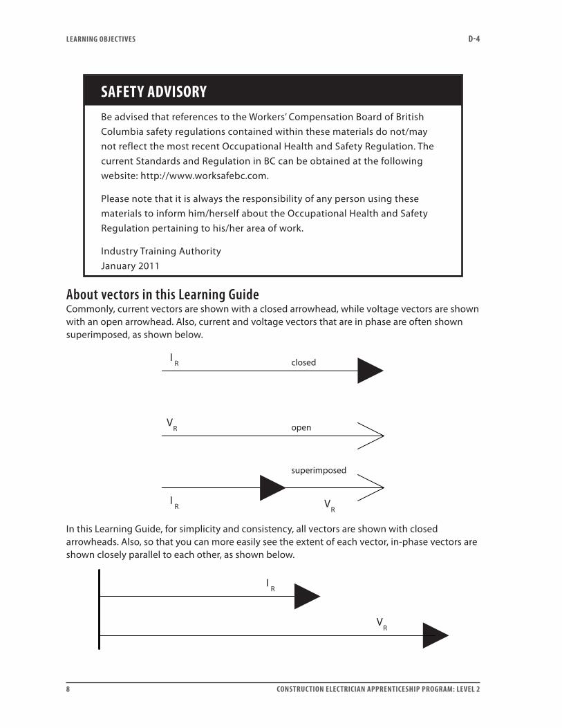
About vectors in this Learning GuideCommonly, current vectors are shown with a closed arrowhead, while voltage vectors are shown with an open arrowhead. Also, current and voltage vectors that are in phase are often shown superimposed, as shown below.
IR
IR
VR
VR
closed
open
superimposed
In this Learning Guide, for simplicity and consistency, all vectors are shown with closed arrowheads. Also, so that you can more easily see the extent of each vector, in-phase vectors are shown closely parallel to each other, as shown below.
IR
VR
CONSTRUCTION ELECTRICIAN APPRENTICESHIP PROGRAM: LEVEL 2 9
Learning Task 1:
Describe the effects of a series AC circuit containing resistance and inductance (R-L)
The effect of resistanceResistance is a measure of opposition to current flow in a circuit. It is measured in ohms. As the voltage applied across a resistor in a circuit increases or decreases, the current flowing through it also increases or decreases. Pure ohmic resistance is considered independent of the frequency of the AC circuit. The relationship between current (I), voltage (V), resistance (R) and power (P) is expressed as:
IVR
P V I= =and
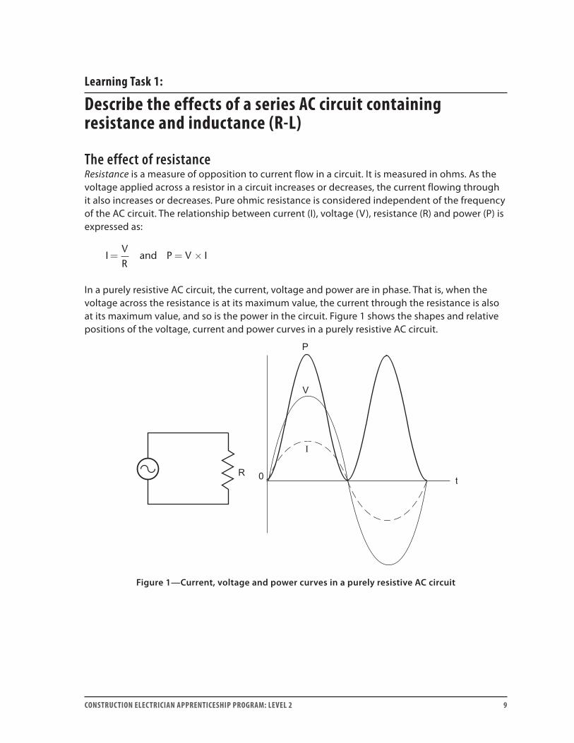
In a purely resistive AC circuit, the current, voltage and power are in phase. That is, when the voltage across the resistance is at its maximum value, the current through the resistance is also at its maximum value, and so is the power in the circuit. Figure 1 shows the shapes and relative positions of the voltage, current and power curves in a purely resistive AC circuit.
Figure 1—Current, voltage and power curves in a purely resistive AC circuit
LEARNING TASk 1 D-4
10 CONSTRUCTION ELECTRICIAN APPRENTICESHIP PROGRAM: LEVEL 2
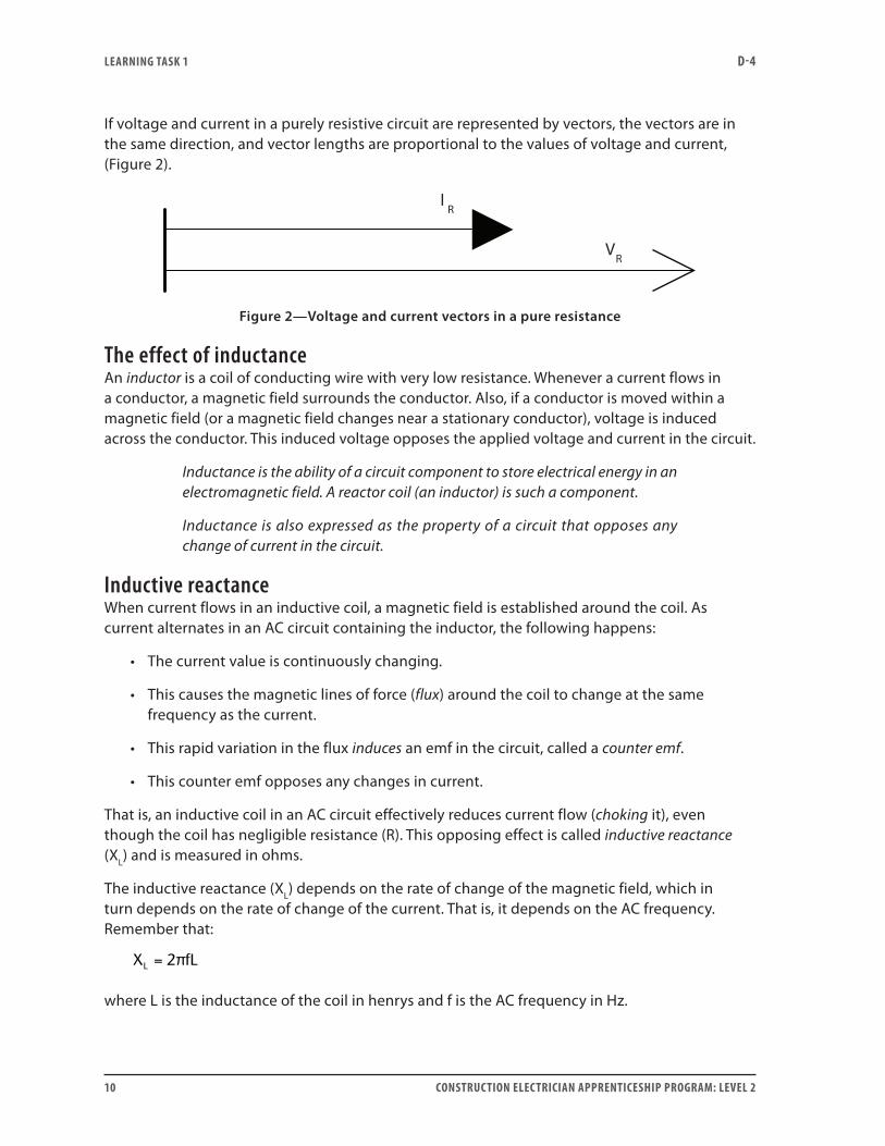
If voltage and current in a purely resistive circuit are represented by vectors, the vectors are in the same direction, and vector lengths are proportional to the values of voltage and current, (Figure 2).
IR
VR
Figure 2—Voltage and current vectors in a pure resistance
The effect of inductanceAn inductor is a coil of conducting wire with very low resistance. Whenever a current flows in a conductor, a magnetic field surrounds the conductor. Also, if a conductor is moved within a magnetic field (or a magnetic field changes near a stationary conductor), voltage is induced across the conductor. This induced voltage opposes the applied voltage and current in the circuit.
Inductance is the ability of a circuit component to store electrical energy in an electromagnetic field. A reactor coil (an inductor) is such a component.
Inductance is also expressed as the property of a circuit that opposes any change of current in the circuit.
Inductive reactanceWhen current flows in an inductive coil, a magnetic field is established around the coil. As current alternates in an AC circuit containing the inductor, the following happens:
• The current value is continuously changing.
• This causes the magnetic lines of force (flux) around the coil to change at the same frequency as the current.
• This rapid variation in the flux induces an emf in the circuit, called a counter emf.
• This counter emf opposes any changes in current.
That is, an inductive coil in an AC circuit effectively reduces current flow (choking it), even though the coil has negligible resistance (R). This opposing effect is called inductive reactance (XL) and is measured in ohms.
The inductive reactance (XL) depends on the rate of change of the magnetic field, which in turn depends on the rate of change of the current. That is, it depends on the AC frequency. Remember that:
X fLL = 2π
where L is the inductance of the coil in henrys and f is the AC frequency in Hz.
LEARNING TASk 1 D-4
CONSTRUCTION ELECTRICIAN APPRENTICESHIP PROGRAM: LEVEL 2 11
Increasing the AC frequency increases the inductive reactance in a circuit. Also, if the coil contains a steel or iron core, the magnetic field is intensified, increasing the inductance L. The variations in the field caused by the alternating current become larger, and the inductive reactance also increases.
Calculating the effect of inductance in the circuit is very similar in some ways to calculating resistance. When a potential difference (V) is applied across an inductor of reactance (XL) through which current (I) flows, replace resistance with reactance in Ohm’s law:
IVXL
=
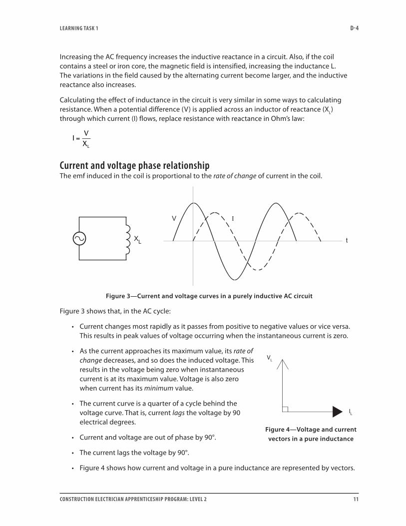
Current and voltage phase relationshipThe emf induced in the coil is proportional to the rate of change of current in the coil.
Figure 3—Current and voltage curves in a purely inductive AC circuit
Figure 3 shows that, in the AC cycle:
• Current changes most rapidly as it passes from positive to negative values or vice versa. This results in peak values of voltage occurring when the instantaneous current is zero.
• As the current approaches its maximum value, its rate of change decreases, and so does the induced voltage. This results in the voltage being zero when instantaneous current is at its maximum value. Voltage is also zero when current has its minimum value.
• The current curve is a quarter of a cycle behind the voltage curve. That is, current lags the voltage by 90 electrical degrees.
• Current and voltage are out of phase by 90°.
• The current lags the voltage by 90°.
• Figure 4 shows how current and voltage in a pure inductance are represented by vectors.
VL
IL
Figure 4—Voltage and current vectors in a pure inductance
LEARNING TASk 1 D-4
12 CONSTRUCTION ELECTRICIAN APPRENTICESHIP PROGRAM: LEVEL 2
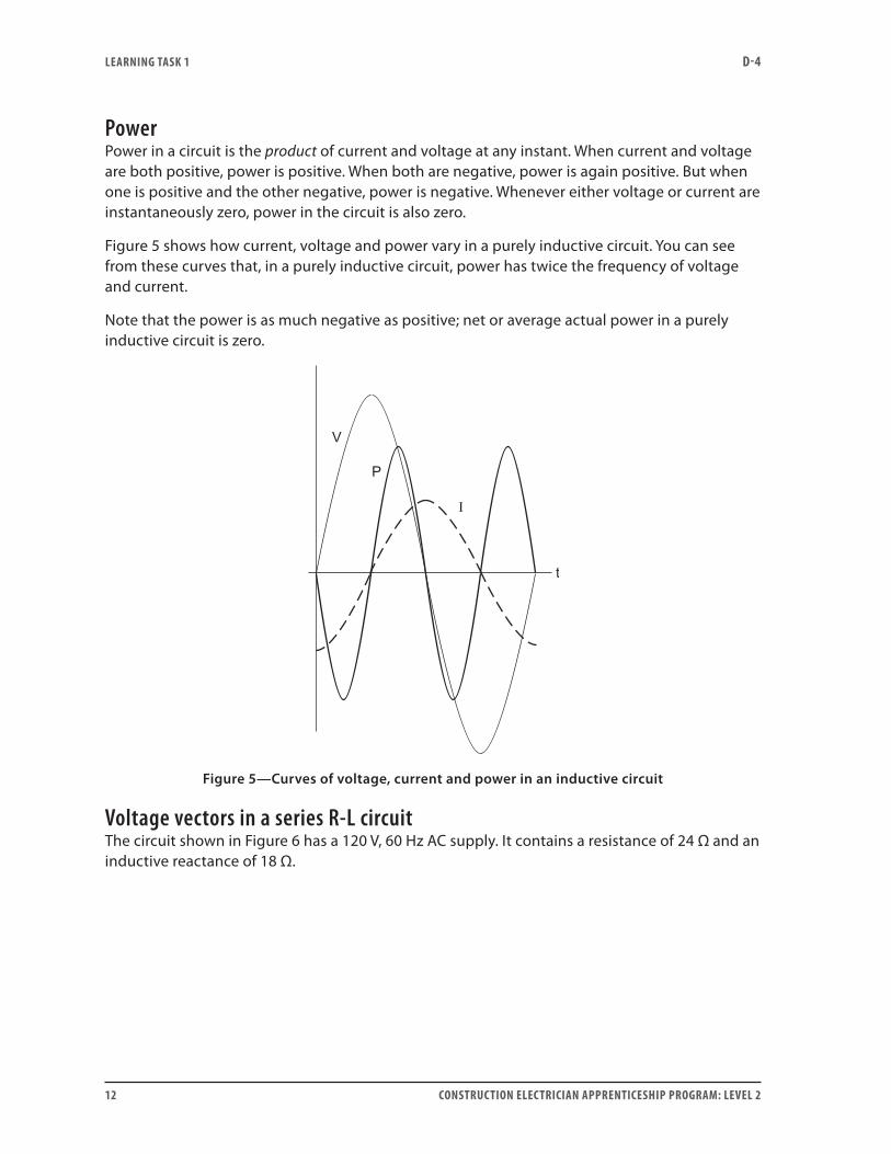
PowerPower in a circuit is the product of current and voltage at any instant. When current and voltage are both positive, power is positive. When both are negative, power is again positive. But when one is positive and the other negative, power is negative. Whenever either voltage or current are instantaneously zero, power in the circuit is also zero.
Figure 5 shows how current, voltage and power vary in a purely inductive circuit. You can see from these curves that, in a purely inductive circuit, power has twice the frequency of voltage and current.
Note that the power is as much negative as positive; net or average actual power in a purely inductive circuit is zero.
Figure 5—Curves of voltage, current and power in an inductive circuit
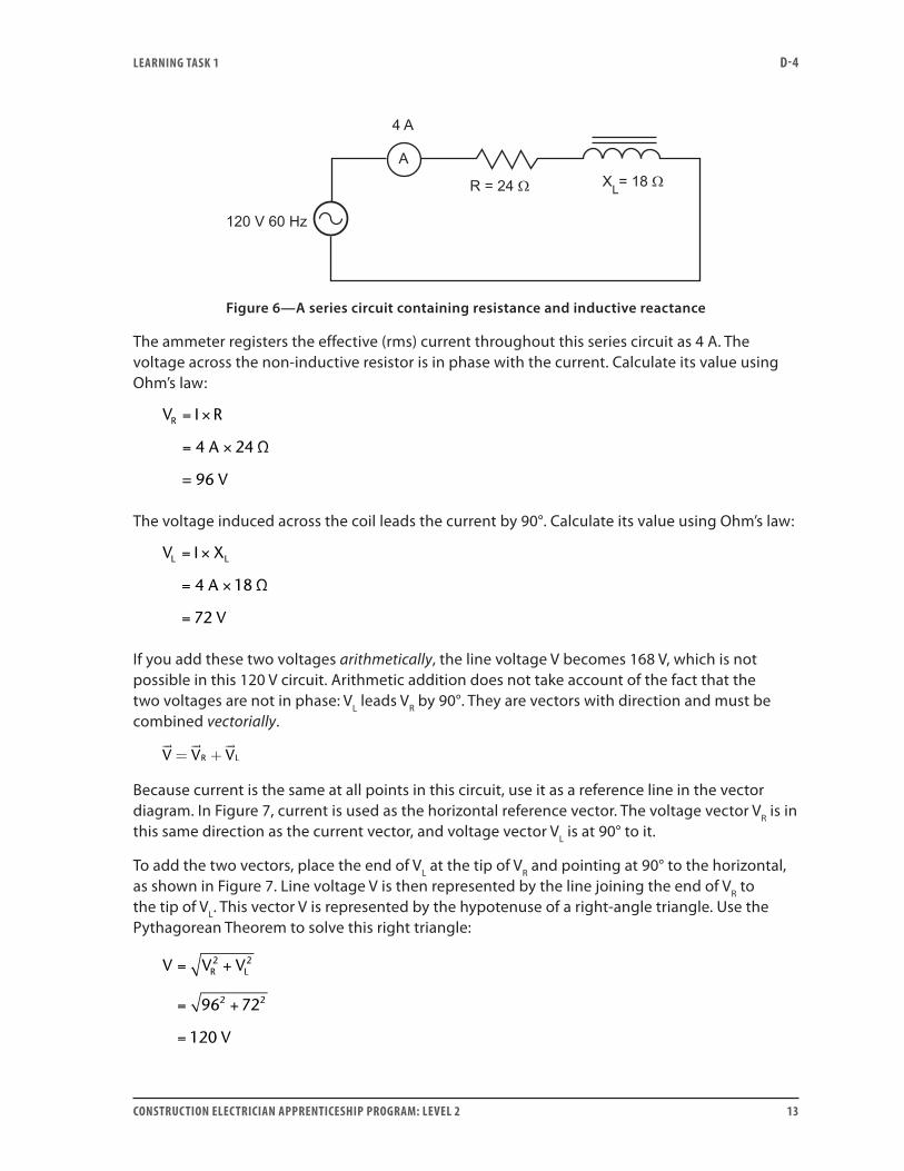
Voltage vectors in a series R-L circuitThe circuit shown in Figure 6 has a 120 V, 60 Hz AC supply. It contains a resistance of 24 Ω and an inductive reactance of 18 Ω.
LEARNING TASk 1 D-4
CONSTRUCTION ELECTRICIAN APPRENTICESHIP PROGRAM: LEVEL 2 13
Figure 6—A series circuit containing resistance and inductive reactance
The ammeter registers the effective (rms) current throughout this series circuit as 4 A. The voltage across the non-inductive resistor is in phase with the current. Calculate its value using Ohm’s law:
V I R
A
R = ×
= ×4 24 Ω
= 96 V
The voltage induced across the coil leads the current by 90°. Calculate its value using Ohm’s law:
V I X
A
V
L L= ×
= ×
=
4 18
72
Ω
If you add these two voltages arithmetically, the line voltage V becomes 168 V, which is not possible in this 120 V circuit. Arithmetic addition does not take account of the fact that the two voltages are not in phase: VL leads VR by 90°. They are vectors with direction and must be combined vectorially.
V V VR L
= +
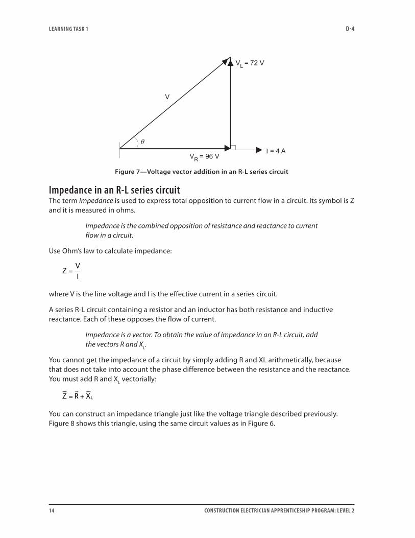
Because current is the same at all points in this circuit, use it as a reference line in the vector diagram. In Figure 7, current is used as the horizontal reference vector. The voltage vector VR is in this same direction as the current vector, and voltage vector VL is at 90° to it.
To add the two vectors, place the end of VL at the tip of VR and pointing at 90° to the horizontal, as shown in Figure 7. Line voltage V is then represented by the line joining the end of VR to the tip of VL. This vector V is represented by the hypotenuse of a right-angle triangle. Use the Pythagorean Theorem to solve this right triangle:
V V V
V
R L= +
= +
=
2 2
2 296 72
120
LEARNING TASk 1 D-4
14 CONSTRUCTION ELECTRICIAN APPRENTICESHIP PROGRAM: LEVEL 2
Figure 7—Voltage vector addition in an R-L series circuit
Impedance in an R-L series circuitThe term impedance is used to express total opposition to current flow in a circuit. Its symbol is Z and it is measured in ohms.
Impedance is the combined opposition of resistance and reactance to current flow in a circuit.
Use Ohm’s law to calculate impedance:
ZVI
=
where V is the line voltage and I is the effective current in a series circuit.
A series R-L circuit containing a resistor and an inductor has both resistance and inductive reactance. Each of these opposes the flow of current.
Impedance is a vector. To obtain the value of impedance in an R-L circuit, add the vectors R and XL.
You cannot get the impedance of a circuit by simply adding R and XL arithmetically, because that does not take into account the phase difference between the resistance and the reactance. You must add R and XL vectorially:
Z R XL
= +
You can construct an impedance triangle just like the voltage triangle described previously. Figure 8 shows this triangle, using the same circuit values as in Figure 6.
LEARNING TASk 1 D-4
CONSTRUCTION ELECTRICIAN APPRENTICESHIP PROGRAM: LEVEL 2 15
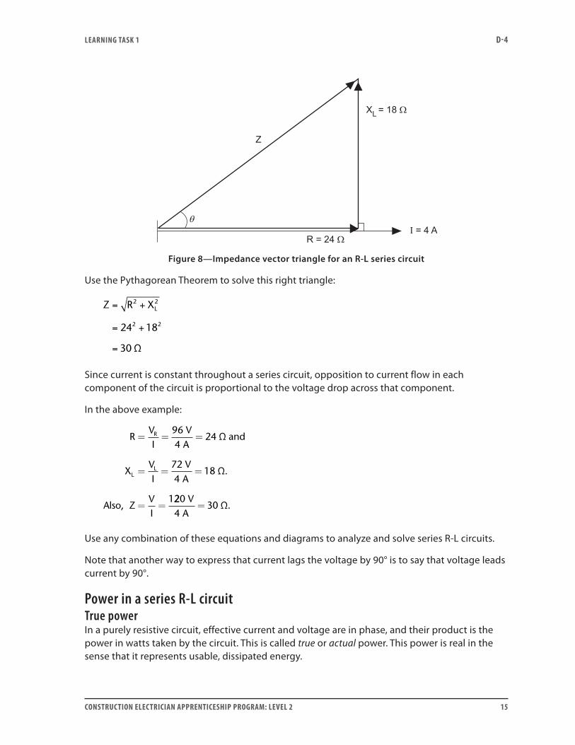
Figure 8—Impedance vector triangle for an R-L series circuit
Use the Pythagorean Theorem to solve this right triangle:
Z R XL= +
= +
=
2 2
2 224 18
30 Ω
Since current is constant throughout a series circuit, opposition to current flow in each component of the circuit is proportional to the voltage drop across that component.
In the above example:
RVI
VA
VA
R= = =
= = =
= =
964
24
724
18
1
Ω and
XVI
Ω.
Also, ZVI
LL
2204
30V
A= Ω.
Use any combination of these equations and diagrams to analyze and solve series R-L circuits.
Note that another way to express that current lags the voltage by 90° is to say that voltage leads current by 90°.
Power in a series R-L circuitTrue powerIn a purely resistive circuit, effective current and voltage are in phase, and their product is the power in watts taken by the circuit. This is called true or actual power. This power is real in the sense that it represents usable, dissipated energy.
LEARNING TASk 1 D-4
16 CONSTRUCTION ELECTRICIAN APPRENTICESHIP PROGRAM: LEVEL 2
In a purely inductive circuit, the current lags the voltage by 90°. True power is not simply calculated by multiplying voltage and current in the inductor. The net true power in watts is zero for a complete AC cycle, because the two negative power pulses balance and cancel the two positive ones. The circuit uses no true power.
In a series circuit containing both resistance and inductive reactance, the current is neither in phase with the line voltage nor lagging it by 90°. The phase angle (angle of lag) is somewhere between zero and 90°, depending on the values of R and XL. The circuit uses some true power.
The true power, measured in watts, in an R-L circuit is all dissipated by the resistance of the circuit.
Calculate true power in a series R-L circuit using one of the following formulas:
P I R or P V I or P V RR R= = = ÷2 2× ×
Using values from our previous example:
True power I R
4 A 24 Ω
384 watts
2
2
= ×
= ×
=
or
True power V I
9 V 4 A
384 watts
R= ×
= ×
=
6
or
True power V ÷ R
9 V ÷ 24 Ω
384 watts
R2
2
=
=
=
6
Reactive powerThere is a form of power associated with the reactance of a circuit. This is reactive (or quadrature) power. To differentiate it from true power, it is often described as wattless power. Reactive power represents the product of voltage and current that are 90° out of phase and is expressed in volts-amperes-reactive, usually abbreviated to VAR(s). Figure 5 on page 12 shows the waveform of reactive power in a purely reactive circuit.
Calculate reactive power in a series R-L circuit using the formula:
Reactive power V IL= ×
LEARNING TASk 1 D-4
CONSTRUCTION ELECTRICIAN APPRENTICESHIP PROGRAM: LEVEL 2 17
Using values from our previous example:
Reactive power 7 V 4 A
288 VARs
= ×
=
2
Also,
Reactive power
A Ω
288 VARs
= ×
= ×
=
I XL2
24 18
and
Reactive power V ÷ X
V ÷ 18 Ω
288 VARs
L2=
=
=
L
722
All these methods of calculation give the same result.
Apparent powerThe two power components (true and reactive) in an R-L series circuit combine to form the apparent power. It is measured in volt-amperes, abbreviated to VA.
In any AC circuit, the simplest way to calculate apparent power is to multiply total line voltage by the total line current. (This current passes through all components in a series circuit.) In the previous example:
Apparent power V
V 4 A
480 VA
= ×
= ×
=
I
120
Because they are all vectors, apparent power cannot be calculated by simply adding true power and reactive power arithmetically. The vectors must be added in a way that takes their phase relationships into account.
VA W VARs
= +
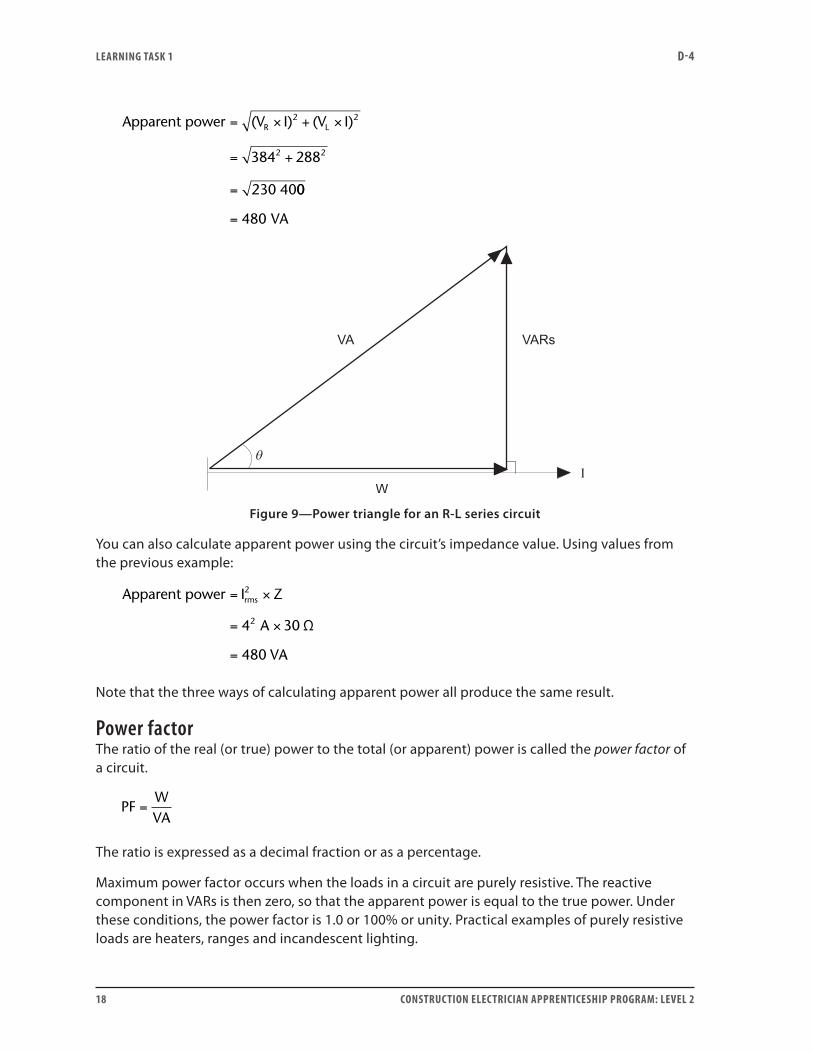
A vector triangle may be drawn for these three power vectors, as shown in Figure 9.
Using the Pythagorean Theorem on this power vector triangle:
VA W VARs2 2= +
Use this formula to calculate apparent power in the previous example:
LEARNING TASk 1 D-4
18 CONSTRUCTION ELECTRICIAN APPRENTICESHIP PROGRAM: LEVEL 2
Apparent power (V I) (V I)
230 40
R2
L2= × + ×
= +
=
384 2882 2
00
VA= 480
Figure 9—Power triangle for an R-L series circuit
You can also calculate apparent power using the circuit’s impedance value. Using values from the previous example:
Apparent power I
Ω
rms2= ×
= ×
=
Z
A
VA
4 30
480
2
Note that the three ways of calculating apparent power all produce the same result.
Power factorThe ratio of the real (or true) power to the total (or apparent) power is called the power factor of a circuit.
PFWVA
=
The ratio is expressed as a decimal fraction or as a percentage.
Maximum power factor occurs when the loads in a circuit are purely resistive. The reactive component in VARs is then zero, so that the apparent power is equal to the true power. Under these conditions, the power factor is 1.0 or 100% or unity. Practical examples of purely resistive loads are heaters, ranges and incandescent lighting.
LEARNING TASk 1 D-4
CONSTRUCTION ELECTRICIAN APPRENTICESHIP PROGRAM: LEVEL 2 19
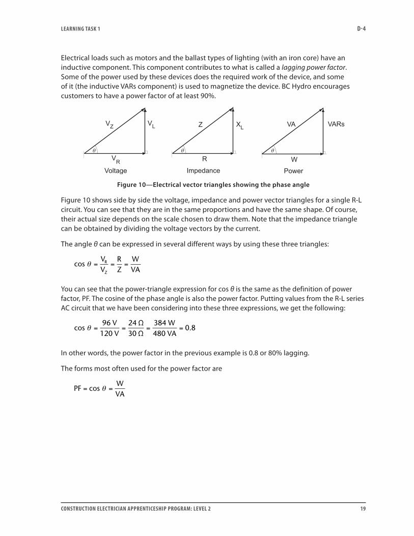
Electrical loads such as motors and the ballast types of lighting (with an iron core) have an inductive component. This component contributes to what is called a lagging power factor. Some of the power used by these devices does the required work of the device, and some of it (the inductive VARs component) is used to magnetize the device. BC Hydro encourages customers to have a power factor of at least 90%.
Figure 10—Electrical vector triangles showing the phase angle
Figure 10 shows side by side the voltage, impedance and power vector triangles for a single R-L circuit. You can see that they are in the same proportions and have the same shape. Of course, their actual size depends on the scale chosen to draw them. Note that the impedance triangle can be obtained by dividing the voltage vectors by the current.
The angle θ can be expressed in several different ways by using these three triangles:
cosVV
R
Z
θ = = =RZ
WVA
You can see that the power-triangle expression for cos θ is the same as the definition of power factor, PF. The cosine of the phase angle is also the power factor. Putting values from the R-L series AC circuit that we have been considering into these three expressions, we get the following:
cos96 V
120 VΩΩ
θ = = = =2430
384480
0 8WVA
.
In other words, the power factor in the previous example is 0.8 or 80% lagging.
The forms most often used for the power factor are
PF = =cosWVA
θ
LEARNING TASk 1 D-4
20 CONSTRUCTION ELECTRICIAN APPRENTICESHIP PROGRAM: LEVEL 2
Rearranging this equation and substituting in VA = V × I, we see that
W VA
V I cos
V I PF
= ×
= × ×
= × ×
cosθ
θ
Resistance of an inductorWhen discussing inductance, it is convenient to imagine a coil that has no ohmic resistance (R). In practice this is not possible, since even good conductors have some resistance, and an inductor is a coil of conducting wire. Before you can calculate impedance, you must add the ohmic resistance of the inductor(s) to the pure resistance in the circuit.
The pure ohmic resistance of the coil is the resistance that would be measured with a direct current passing through the coil. But the effective resistance of a coil is a combination of several factors. Inductors are used in AC circuits, and the alternating current causes their effective resistance to increase in several ways: through skin effect, through eddy currents, through hysteresis loss and through dielectric loss. In each of these effects, some power is used, decreasing the useful, available power in the circuit and increasing the effective resistance.
Figure of merit (Q)In a commercial inductor, the useful component is the inductive reactance. Effective resistance is the unwanted component, and it is important that the value of reactance be high compared to effective resistance. Such coils are assigned a figure of merit, which has the symbol Q.
QXR
fLR
L= =2π
A coil with a high figure of merit (Q) has a large reactance compared to its resistance and relatively little power loss. Coils with a low Q value have relatively high effective resistance, and there is a large power loss when they are used.
Note that both the reactance and the effective resistance of the coil depend on the frequency in the circuit, although in different proportions. However, its effect on reactance is relatively much larger. The Q value must be determined for the band frequencies at which the coil will be used.
Now do Self-Test 1 and check your answers.

LEARNING TASk 1 D-4
CONSTRUCTION ELECTRICIAN APPRENTICESHIP PROGRAM: LEVEL 2 21
Self-Test 1
1. What is the angle between current and voltage vectors in a purely resistive circuit?
2. Inductive reactance is measured in:
a. henrys (H)
b. ohms (Ω)
c. hertz (Hz)
d. volt-amperes (VA)
3. In a purely inductive circuit, current (leads, lags) the voltage by 90°.
4. When instantaneous current and voltage are both negative in a purely inductive AC circuit, the instantaneous power value is:
a. positive
b. negative
5. Why don’t you arithmetically add the voltages across the resistor and inductor in a series AC circuit?
6. Define impedance (Z).
7. Express impedance as a vector equation for an AC series, R-L circuit.

LEARNING TASk 1 D-4
22 CONSTRUCTION ELECTRICIAN APPRENTICESHIP PROGRAM: LEVEL 2
8. Where is the true power, measured in watts, dissipated in a series, R-L circuit?
9. What type of power is measured in VARs, and with which part of an R-L circuit is it associated?
10. If you know the values of true power (W) and reactive power (VARs) in a circuit, how do you calculate apparent power (VA)?
11. What is the significance of the power factor of an AC circuit?
12. In the expression PF = cos θ, what is the significance of angle θ? Give at least two places where it occurs.
Go to the Answer Key at the end of the Learning Guide to check your answers.
CONSTRUCTION ELECTRICIAN APPRENTICESHIP PROGRAM: LEVEL 2 23
Learning Task 2:
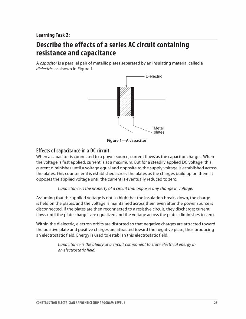
Describe the effects of a series AC circuit containing resistance and capacitanceA capacitor is a parallel pair of metallic plates separated by an insulating material called a dielectric, as shown in Figure 1.
Figure 1—A capacitor
Effects of capacitance in a DC circuitWhen a capacitor is connected to a power source, current flows as the capacitor charges. When the voltage is first applied, current is at a maximum. But for a steadily applied DC voltage, this current diminishes until a voltage equal and opposite to the supply voltage is established across the plates. This counter emf is established across the plates as the charges build up on them. It opposes the applied voltage until the current is eventually reduced to zero.
Capacitance is the property of a circuit that opposes any change in voltage.
Assuming that the applied voltage is not so high that the insulation breaks down, the charge is held on the plates, and the voltage is maintained across them even after the power source is disconnected. If the plates are then reconnected to a resistive circuit, they discharge; current flows until the plate charges are equalized and the voltage across the plates diminishes to zero.
Within the dielectric, electron orbits are distorted so that negative charges are attracted toward the positive plate and positive charges are attracted toward the negative plate, thus producing an electrostatic field. Energy is used to establish this electrostatic field.
Capacitance is the ability of a circuit component to store electrical energy in an electrostatic field.
LEARNING TASk 2 D-4
24 CONSTRUCTION ELECTRICIAN APPRENTICESHIP PROGRAM: LEVEL 2
Effects of capacitance in an AC circuitWhen the supply voltage to a capacitor is from an alternating power source, the following happens:
• The voltage value is continuously changing.
• Current flows in the circuit alternating at the same frequency as the applied voltage; the capacitor plates repeatedly charge and discharge.
• An electrostatic field that alternates direction (polarity) at the applied frequency is established in the dielectric.
• A counter emf is established across the plates at the same frequency as the applied voltage. This voltage opposes the current flow.
Capacitive reactanceLike the inductor, a capacitor produces a counter emf into the AC circuit. The counter emf opposes current flow. This effect is called capacitive reactance (XC) and is measured in ohms. It is calculated by using Ohm’s law:
IVXC
C
C
=
where:
IC = current in the capacitive circuit, in amps VC = voltage across the capacitor, in volts XC = reactance of the capacitor, in ohms
Remember that capacitance in farads is the amount of charge moved by 1 volt applied across the capacitor plates. This is a very large unit and commercial capacitors more often have capacitance ratings in microfarads (µF).
1 F 10 F and 10 F 1 F6 = =−6
• When capacitance is high, more charge is moved for a given voltage, so that current is higher. This means that opposition to current flow (reactance) is lower.
• When the frequency of the applied voltage is high, the rate of change of charge is also high—that is, the current is high. Opposition to current (reactance) is low.
This means that reactance is inversely proportional to capacitance and frequency. The relationship is expressed by the formula:
XfCC =
12≠
LEARNING TASk 2 D-4
CONSTRUCTION ELECTRICIAN APPRENTICESHIP PROGRAM: LEVEL 2 25
where:
f = AC frequency in hertz C = capacitance in farads XC = capacitive reactance in ohms
Since capacitance is usually given in µF, this formula is often written as:
XfCC =
102
6
π
where:
f = AC frequency in hertz C = capacitance in microfarads XC = capacitive reactance in ohms
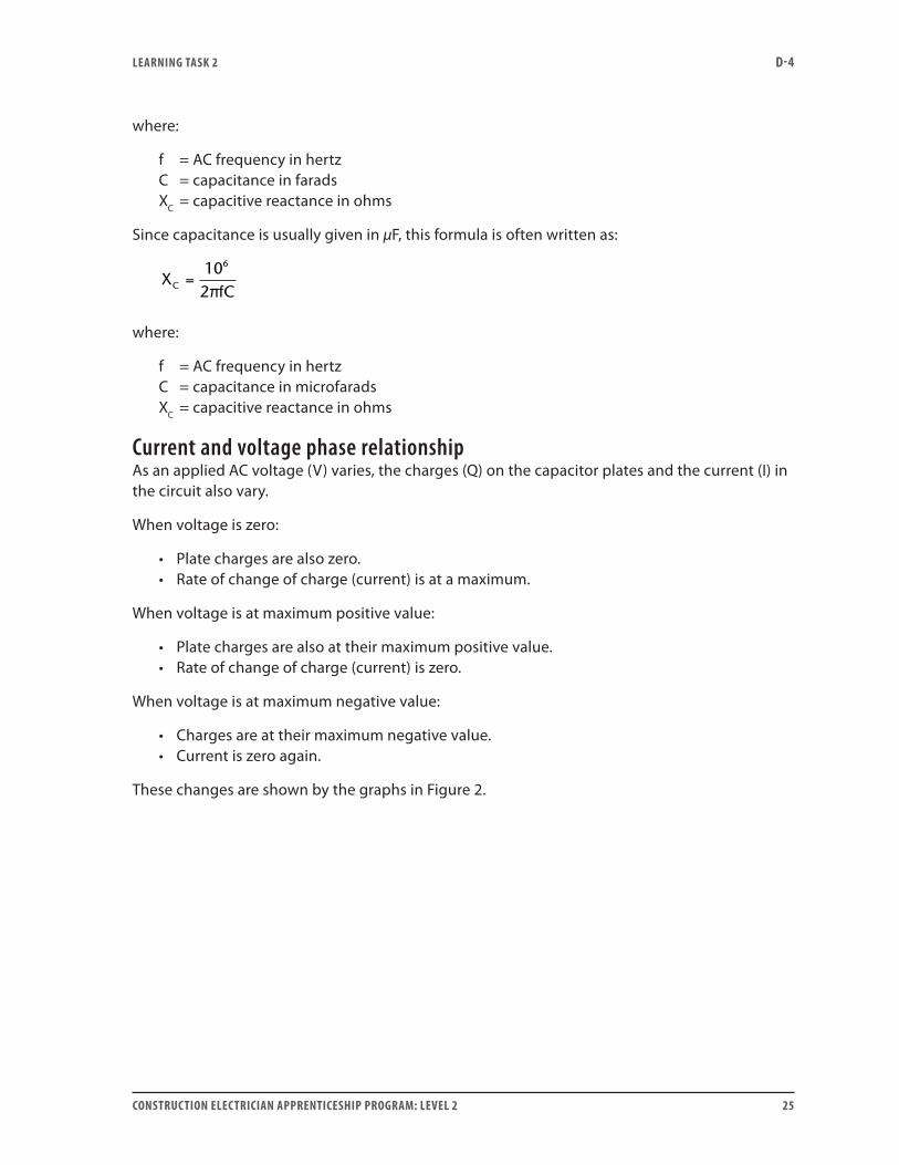
Current and voltage phase relationshipAs an applied AC voltage (V) varies, the charges (Q) on the capacitor plates and the current (I) in the circuit also vary.
When voltage is zero:
• Plate charges are also zero.• Rate of change of charge (current) is at a maximum.
When voltage is at maximum positive value:
• Plate charges are also at their maximum positive value.• Rate of change of charge (current) is zero.
When voltage is at maximum negative value:
• Charges are at their maximum negative value.• Current is zero again.
These changes are shown by the graphs in Figure 2.
LEARNING TASk 2 D-4
26 CONSTRUCTION ELECTRICIAN APPRENTICESHIP PROGRAM: LEVEL 2
Figure 2—Voltage, charge and current curves in a purely capacitive AC circuit
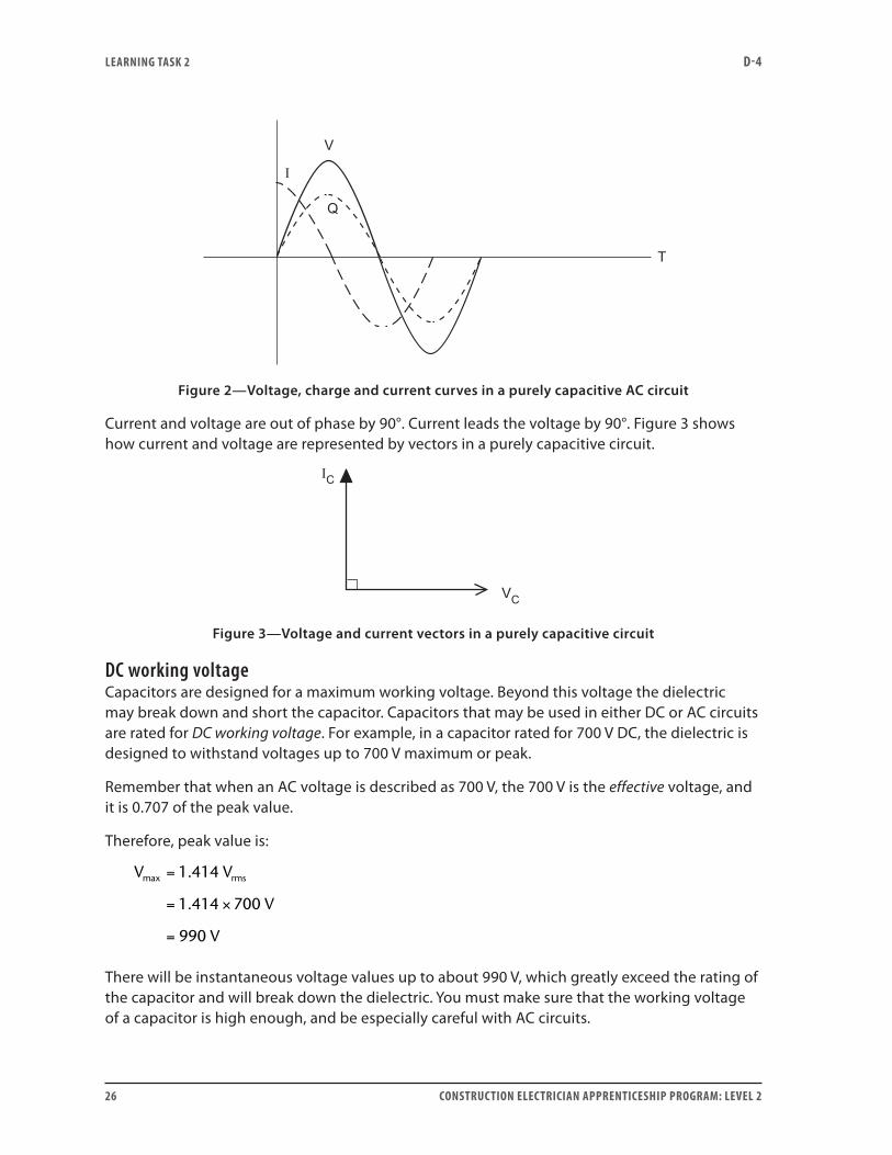
Current and voltage are out of phase by 90°. Current leads the voltage by 90°. Figure 3 shows how current and voltage are represented by vectors in a purely capacitive circuit.
Figure 3—Voltage and current vectors in a purely capacitive circuit
DC working voltageCapacitors are designed for a maximum working voltage. Beyond this voltage the dielectric may break down and short the capacitor. Capacitors that may be used in either DC or AC circuits are rated for DC working voltage. For example, in a capacitor rated for 700 V DC, the dielectric is designed to withstand voltages up to 700 V maximum or peak.
Remember that when an AC voltage is described as 700 V, the 700 V is the effective voltage, and it is 0.707 of the peak value.
Therefore, peak value is:
V V
V
V
rmsmax .
.
=
= ×
=
1 414
1 414 700
990
There will be instantaneous voltage values up to about 990 V, which greatly exceed the rating of the capacitor and will break down the dielectric. You must make sure that the working voltage of a capacitor is high enough, and be especially careful with AC circuits.
LEARNING TASk 2 D-4
CONSTRUCTION ELECTRICIAN APPRENTICESHIP PROGRAM: LEVEL 2 27
In AC circuits, use only capacitors designed for such use, since the constantly reversing polarity of AC causes extra stress in the dielectric, increasing the power loss and the likelihood of breakdown.
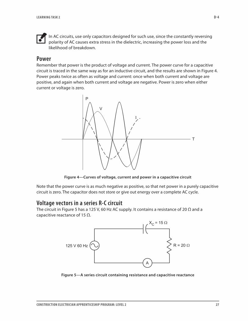
PowerRemember that power is the product of voltage and current. The power curve for a capacitive circuit is traced in the same way as for an inductive circuit, and the results are shown in Figure 4. Power peaks twice as often as voltage and current: once when both current and voltage are positive, and again when both current and voltage are negative. Power is zero when either current or voltage is zero.
Figure 4—Curves of voltage, current and power in a capacitive circuit
Note that the power curve is as much negative as positive, so that net power in a purely capacitive circuit is zero. The capacitor does not store or give out energy over a complete AC cycle.
Voltage vectors in a series R-C circuitThe circuit in Figure 5 has a 125 V, 60 Hz AC supply. It contains a resistance of 20 Ω and a capacitive reactance of 15 Ω.
Figure 5—A series circuit containing resistance and capacitive reactance
LEARNING TASk 2 D-4
28 CONSTRUCTION ELECTRICIAN APPRENTICESHIP PROGRAM: LEVEL 2
The ammeter registers the effective (rms) current throughout the circuit as 5 A. The voltage VR across the pure resistance is in phase with the line current:
V I R
A
V
R = ×
= ×
=
5 20
100
Ω
The voltage across the capacitor lags the line current by 90°. Another way to express this is to say that the line current leads the voltage across the capacitor by 90°. Its value is calculated by using Ohm’s law:
V I X
A
V
C C= ×
= ×
=
5 15
75
Ω
If you add these two voltages arithmetically, the line voltage becomes 175 V, which is not possible in this 125 V circuit. Arithmetic addition does not take account of the fact that the two voltages are not in phase: VC lags VR by 90°. They are vectors with direction and must be combined vectorially.
V V VR C
= +
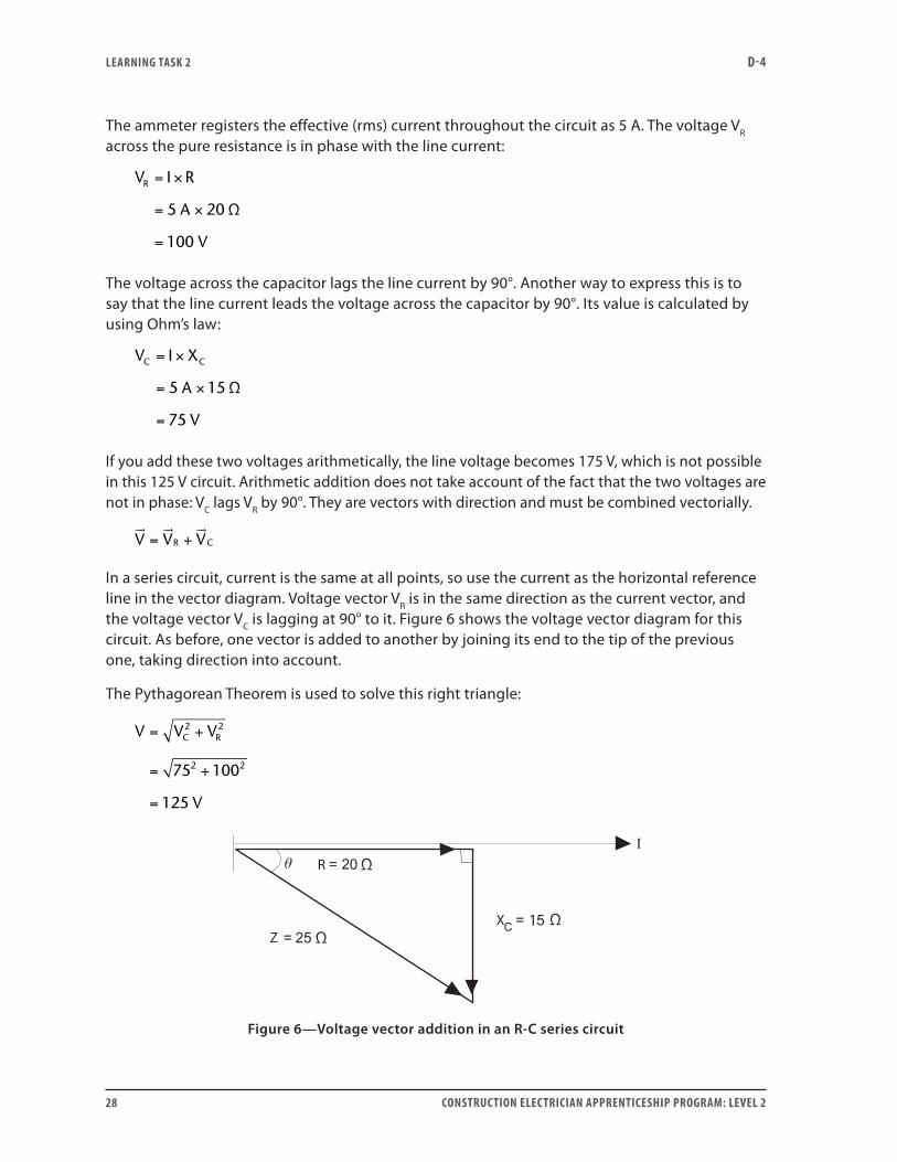
In a series circuit, current is the same at all points, so use the current as the horizontal reference line in the vector diagram. Voltage vector VR is in the same direction as the current vector, and the voltage vector VC is lagging at 90° to it. Figure 6 shows the voltage vector diagram for this circuit. As before, one vector is added to another by joining its end to the tip of the previous one, taking direction into account.
The Pythagorean Theorem is used to solve this right triangle:
V V V
V
C R= +
= +
=
2 2
2 275 100
125
ΩR
Z ΩX 1 Ω
Figure 6—Voltage vector addition in an R-C series circuit
LEARNING TASk 2 D-4
CONSTRUCTION ELECTRICIAN APPRENTICESHIP PROGRAM: LEVEL 2 29
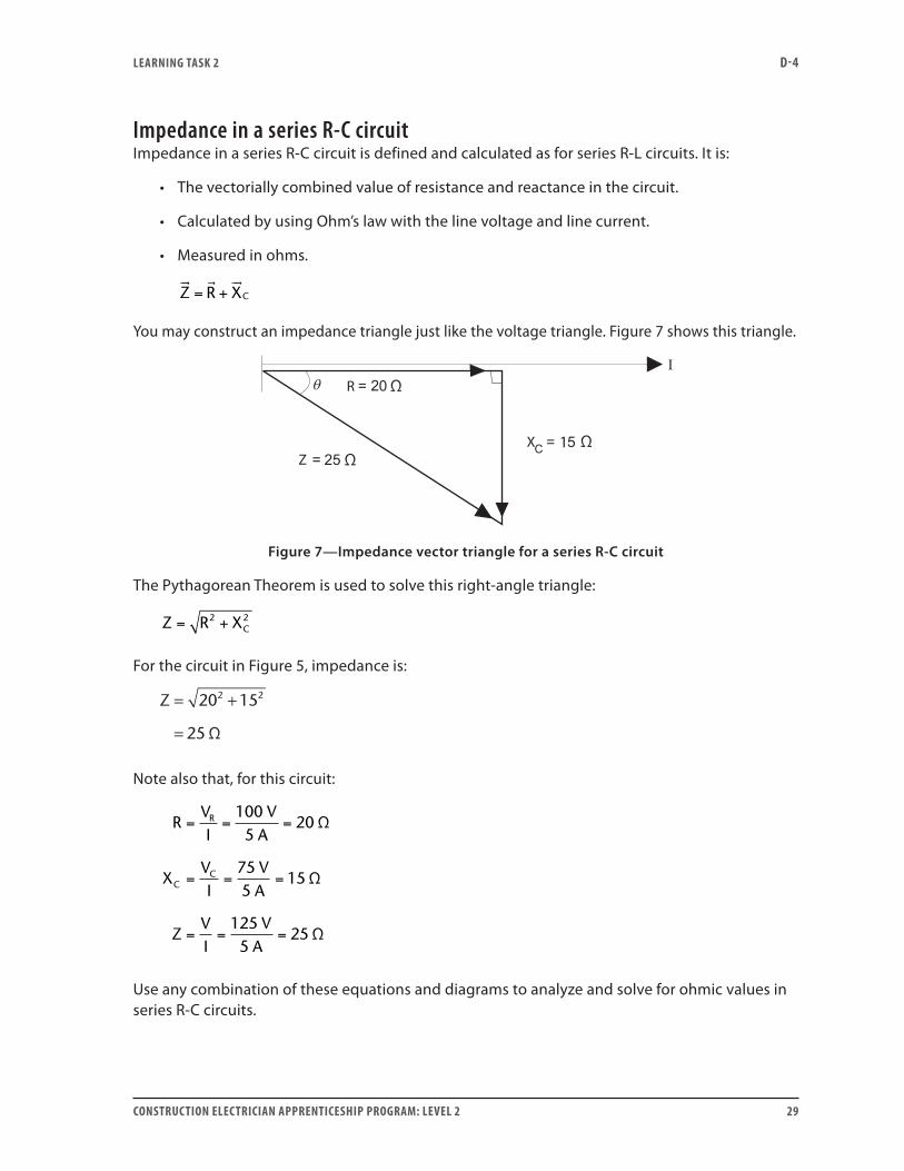
Impedance in a series R-C circuitImpedance in a series R-C circuit is defined and calculated as for series R-L circuits. It is:
• The vectorially combined value of resistance and reactance in the circuit.
• Calculated by using Ohm’s law with the line voltage and line current.
• Measured in ohms.
Z R XC
= +
You may construct an impedance triangle just like the voltage triangle. Figure 7 shows this triangle.
ΩR
Z ΩX 1 Ω
Figure 7—Impedance vector triangle for a series R-C circuit
The Pythagorean Theorem is used to solve this right-angle triangle:
Z R XC= +2 2
For the circuit in Figure 5, impedance is:
Z = +
=
20 15
25
2 2
Ω
Note also that, for this circuit:
RVI
VA
XVI
VA
ZVI
VA
R
CC
= = =
= = =
= = =
1005
20
755
15
1255
25
Ω
Ω
Ω
Use any combination of these equations and diagrams to analyze and solve for ohmic values in series R-C circuits.
LEARNING TASk 2 D-4
30 CONSTRUCTION ELECTRICIAN APPRENTICESHIP PROGRAM: LEVEL 2
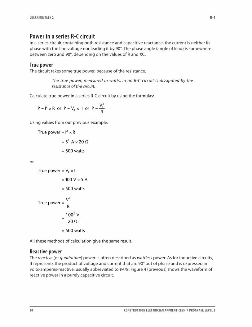
Power in a series R-C circuitIn a series circuit containing both resistance and capacitive reactance, the current is neither in phase with the line voltage nor leading it by 90°. The phase angle (angle of lead) is somewhere between zero and 90°, depending on the values of R and XC.
True powerThe circuit takes some true power, because of the resistance.
The true power, measured in watts, in an R-C circuit is dissipated by the resistance of the circuit.
Calculate true power in a series R-C circuit by using the formulas:
P I R or P V I or PV2
RR2
= × = × =R
Using values from our previous example:
True power I R
5 A 20 Ω
500 watts
2
2
= ×
= ×
=
or
True power V I
1 V A
500 watts
= ×
= ×
=
R
00 5
True power
Ω
500 watts
=
=
=
VR
V
2
210020
All these methods of calculation give the same result.
Reactive powerThe reactive (or quadrature) power is often described as wattless power. As for inductive circuits, it represents the product of voltage and current that are 90° out of phase and is expressed in volts-amperes-reactive, usually abbreviated to VARs. Figure 4 (previous) shows the waveform of reactive power in a purely capacitive circuit.
LEARNING ObjECTIVES D-4
CONSTRUCTION ELECTRICIAN APPRENTICESHIP PROGRAM: LEVEL 2 31
To calculate reactive power in a series R-C circuit, use the values from the previous example in the following formulas:
Reactive power V I
75 V 5 A
375 VARs
C= ×
= ×
=
or
Reactive power I
5 A 5 Ω
375 VARs
2
= ×
= ×
=
2
1
XC
or
Reactive power
75 VΩ
375 VARs
2
=
=
=
EXC
2
15
All of these methods of calculation give the same result.
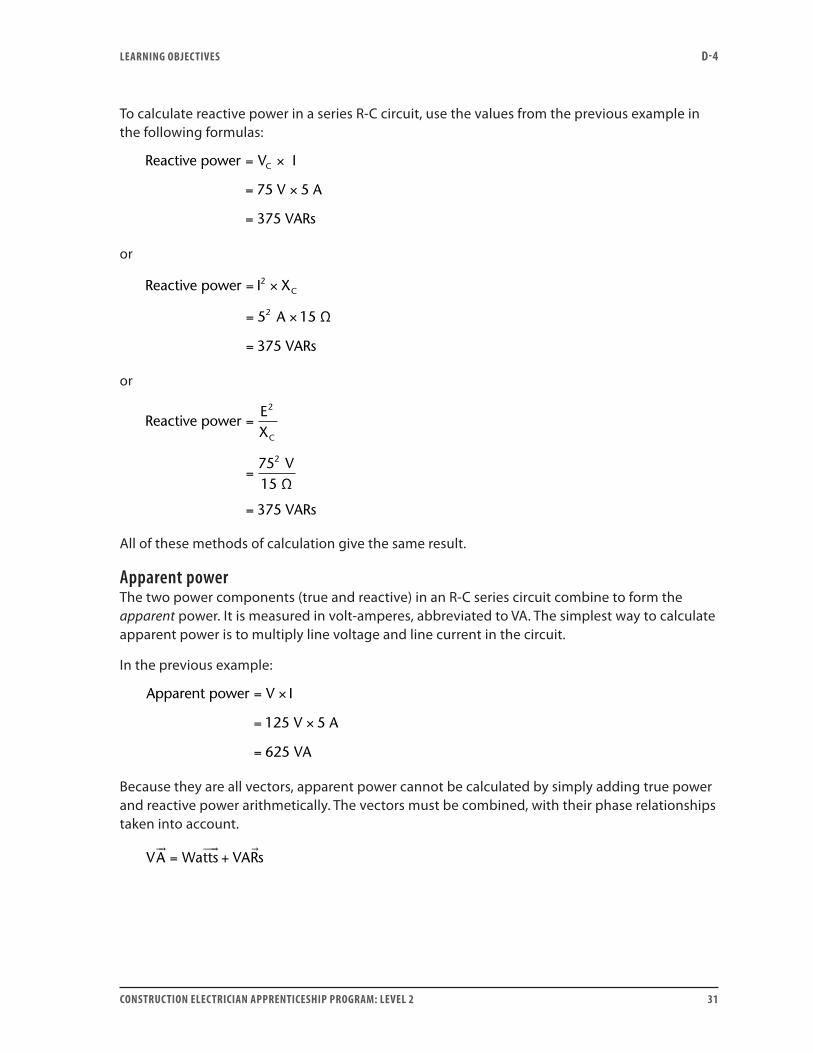
Apparent powerThe two power components (true and reactive) in an R-C series circuit combine to form the apparent power. It is measured in volt-amperes, abbreviated to VA. The simplest way to calculate apparent power is to multiply line voltage and line current in the circuit.
In the previous example:
Apparent power
V 5 A
VA
= ×
= ×
=
V I
125
625
Because they are all vectors, apparent power cannot be calculated by simply adding true power and reactive power arithmetically. The vectors must be combined, with their phase relationships taken into account.
VA Watts VARs
= +
LEARNING TASk 2 D-4
32 CONSTRUCTION ELECTRICIAN APPRENTICESHIP PROGRAM: LEVEL 2
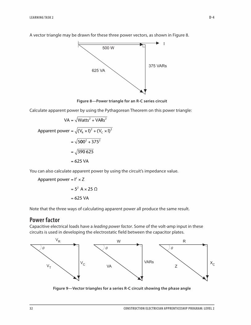
A vector triangle may be drawn for these three power vectors, as shown in Figure 8.
Figure 8—Power triangle for an R-C series circuit
Calculate apparent power by using the Pythagorean Theorem on this power triangle:
VA Watts VARs
V I V IR C
= +
= × + ×
=
2 2
2 2
5
Apparent power ( ) ( )
000 375
390 625
625
2 2+
=
= VA
You can also calculate apparent power by using the circuit’s impedance value.
Apparent power I Z
5 A 25 Ω
625 VA
2
2
= ×
= ×
=
Note that the three ways of calculating apparent power all produce the same result.
Power factorCapacitive electrical loads have a leading power factor. Some of the volt-amp input in these circuits is used in developing the electrostatic field between the capacitor plates.
Figure 9—Vector triangles for a series R-C circuit showing the phase angle
LEARNING TASk 2 D-4
CONSTRUCTION ELECTRICIAN APPRENTICESHIP PROGRAM: LEVEL 2 33
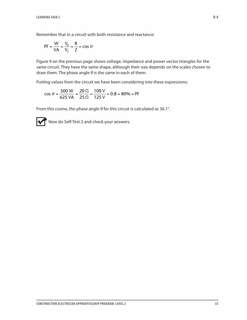
Remember that in a circuit with both resistance and reactance:
PFWVA
VV
RZ
R
Z
= = = = cos θ
Figure 9 on the previous page shows voltage, impedance and power vector triangles for the same circuit. They have the same shape, although their size depends on the scales chosen to draw them. The phase angle θ is the same in each of them.
Putting values from the circuit we have been considering into these expressions:
cos500 W625 VA
ΩΩ
θ = = = = = =2025
100125
0 8 80VV
PF. %
From this cosine, the phase angle θ for this circuit is calculated as 36.1°.
Now do Self-Test 2 and check your answers.

LEARNING TASk 2 D-4
34 CONSTRUCTION ELECTRICIAN APPRENTICESHIP PROGRAM: LEVEL 2
Self-Test 2
1. Capacitive reactance is measured in:
a. ohms
b. farads
c. microfarads
d. VARs
2. In a purely capacitive circuit, current (leads, lags) the voltage by 90°.
3. In a purely capacitive circuit, when the instantaneous current is zero and the instantaneous voltage is at its positive peak value, the instantaneous power value is:
a. positive
b. negative
c. zero
d. unable to be determined without values
4. A series R-C circuit differs from a series R-L circuit in that the voltage across the resistor leads the voltage across the capacitor and can be added to it arithmetically.
a. True
b. False
5. Write an equation expressing the vector relationship between resistance, capacitive reactance and impedance in a series R-C circuit.
6. True power in a series R-C circuit is:
a. zero because net power developed in a capacitor in an AC circuit is zero
b. developed almost entirely in the resistance of the circuit
c. developed only in the electrostatic field in the dielectric
d. the product of line volts times line amps

LEARNING TASk 2 D-4
CONSTRUCTION ELECTRICIAN APPRENTICESHIP PROGRAM: LEVEL 2 35
7. If you know the true and apparent power in a series R-C circuit, how do you calculate the volts-amps-reactive?
8. What is the relationship between the phase angle of a circuit and its power factor?
Go to the Answer Key at the end of the Learning Guide to check your answers.

36 CONSTRUCTION ELECTRICIAN APPRENTICESHIP PROGRAM: LEVEL 2
CONSTRUCTION ELECTRICIAN APPRENTICESHIP PROGRAM: LEVEL 2 37
Learning Task 3:
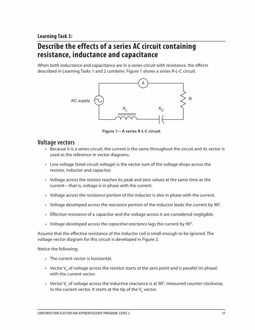
Describe the effects of a series AC circuit containing resistance, inductance and capacitanceWhen both inductance and capacitance are in a series circuit with resistance, the effects described in Learning Tasks 1 and 2 combine. Figure 1 shows a series R-L-C circuit.
Figure 1—A series R-L-C circuit
Voltage vectors• Because it is a series circuit, the current is the same throughout the circuit and its vector is
used as the reference in vector diagrams.
• Line voltage (total circuit voltage) is the vector sum of the voltage drops across the resistor, inductor and capacitor.
• Voltage across the resistor reaches its peak and zero values at the same time as the current—that is, voltage is in phase with the current.
• Voltage across the resistance portion of the inductor is also in phase with the current.
• Voltage developed across the reactance portion of the inductor leads the current by 90°.
• Effective resistance of a capacitor and the voltage across it are considered negligible.
• Voltage developed across the capacitive reactance lags the current by 90°.
Assume that the effective resistance of the inductor coil is small enough to be ignored. The voltage vector diagram for this circuit is developed in Figure 2.
Notice the following:
• The current vector is horizontal.
• Vector VR of voltage across the resistor starts at the zero point and is parallel (in phase) with the current vector.
• Vector VL of voltage across the inductive reactance is at 90°, measured counter-clockwise, to the current vector. It starts at the tip of the VR vector.
LEARNING TASk 3 D-4
38 CONSTRUCTION ELECTRICIAN APPRENTICESHIP PROGRAM: LEVEL 2
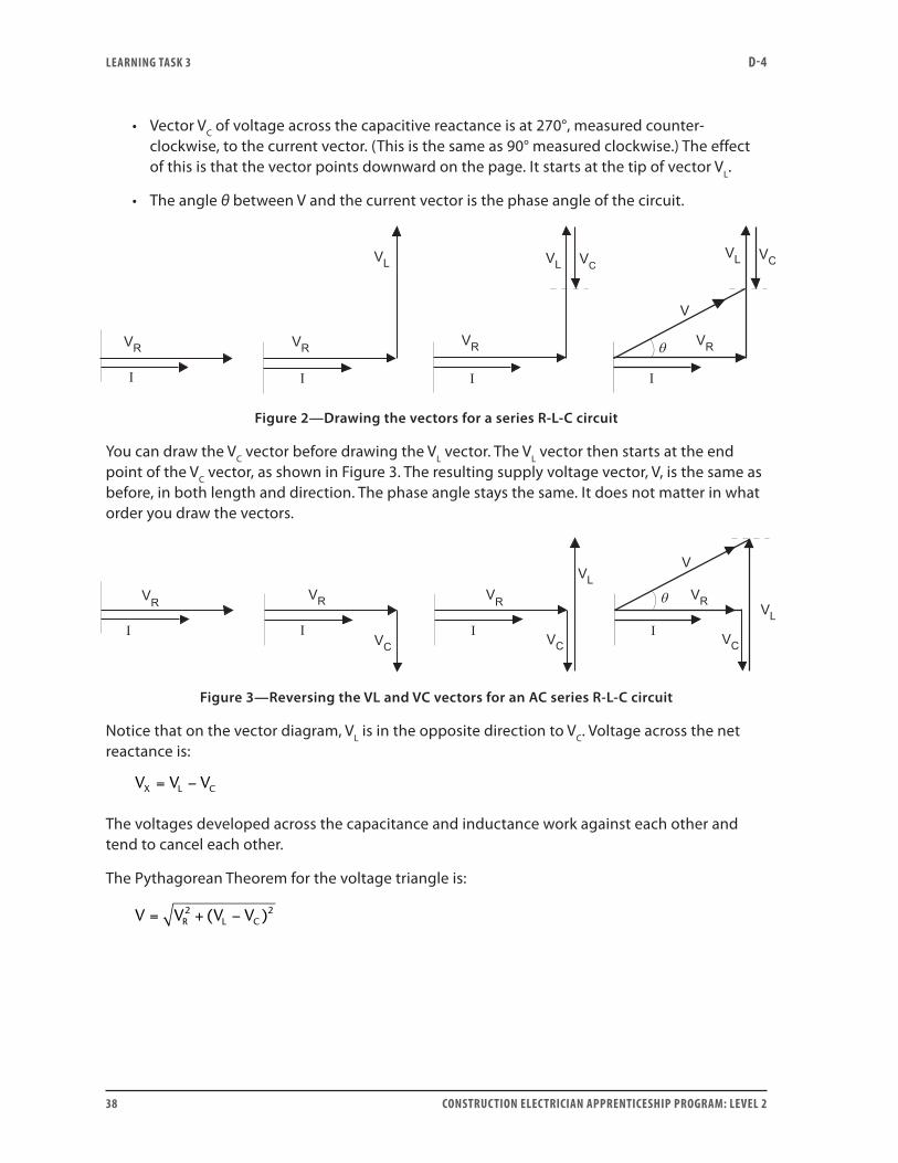
• Vector VC of voltage across the capacitive reactance is at 270°, measured counter-clockwise, to the current vector. (This is the same as 90° measured clockwise.) The effect of this is that the vector points downward on the page. It starts at the tip of vector VL.
• The angle θ between V and the current vector is the phase angle of the circuit.
Figure 2—Drawing the vectors for a series R-L-C circuit
You can draw the VC vector before drawing the VL vector. The VL vector then starts at the end point of the VC vector, as shown in Figure 3. The resulting supply voltage vector, V, is the same as before, in both length and direction. The phase angle stays the same. It does not matter in what order you draw the vectors.
Figure 3—Reversing the VL and VC vectors for an AC series R-L-C circuit
Notice that on the vector diagram, VL is in the opposite direction to VC. Voltage across the net reactance is:
V V VX L C= −
The voltages developed across the capacitance and inductance work against each other and tend to cancel each other.
The Pythagorean Theorem for the voltage triangle is:
V V V VR L C= + −2 2( )
LEARNING TASk 3 D-4
CONSTRUCTION ELECTRICIAN APPRENTICESHIP PROGRAM: LEVEL 2 39
Notice that it is possible for VL and VC each to be very large—much larger than the line voltage. These voltages have zero net effect in the circuit, but individually they may be high and an electrical hazard.
• If either VL or VC is much larger than the other, then VX is larger and the phase angle of the circuit is much larger as well.
• When either the inductive or capacitive reactance is much larger than the other, the net reactance acts in the direction of the largest component.
• The phase angle’s direction (either leading or lagging) also depends on the relative sizes of the inductive and capacitive reactance in the circuit.
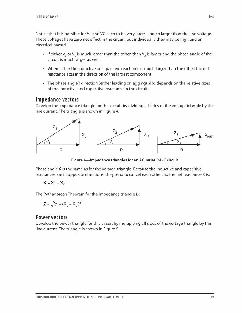
Impedance vectorsDevelop the impedance triangle for this circuit by dividing all sides of the voltage triangle by the line current. The triangle is shown in Figure 4.
Figure 4—Impedance triangles for an AC series R-L-C circuit
Phase angle θ is the same as for the voltage triangle. Because the inductive and capacitive reactances are in opposite directions, they tend to cancel each other. So the net reactance X is:
X X XL C= −
The Pythagorean Theorem for the impedance triangle is:
Z R X XL C= + −2 2( )
Power vectorsDevelop the power triangle for this circuit by multiplying all sides of the voltage triangle by the line current. The triangle is shown in Figure 5.
LEARNING TASk 3 D-4
40 CONSTRUCTION ELECTRICIAN APPRENTICESHIP PROGRAM: LEVEL 2
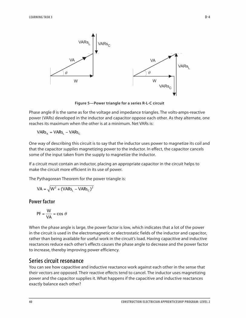
Figure 5—Power triangle for a series R-L-C circuit
Phase angle θ is the same as for the voltage and impedance triangles. The volts-amps-reactive power (VARs) developed in the inductor and capacitor oppose each other. As they alternate, one reaches its maximum when the other is at a minimum. Net VARs is:
VARs VARs VARsX L C= −
One way of describing this circuit is to say that the inductor uses power to magnetize its coil and that the capacitor supplies magnetizing power to the inductor. In effect, the capacitor cancels some of the input taken from the supply to magnetize the inductor.
If a circuit must contain an inductor, placing an appropriate capacitor in the circuit helps to make the circuit more efficient in its use of power.
The Pythagorean Theorem for the power triangle is:
VA W VARs VARsL C= + −2 2( )
Power factor
PFWVA
= = cos θ
When the phase angle is large, the power factor is low, which indicates that a lot of the power in the circuit is used in the electromagnetic or electrostatic fields of the inductor and capacitor, rather than being available for useful work in the circuit’s load. Having capacitive and inductive reactances reduce each other’s effects causes the phase angle to decrease and the power factor to increase, thereby improving power efficiency.
Series circuit resonanceYou can see how capacitive and inductive reactance work against each other in the sense that their vectors are opposed. Their reactive effects tend to cancel. The inductor uses magnetizing power and the capacitor supplies it. What happens if the capacitive and inductive reactances exactly balance each other?
LEARNING TASk 3 D-4
CONSTRUCTION ELECTRICIAN APPRENTICESHIP PROGRAM: LEVEL 2 41
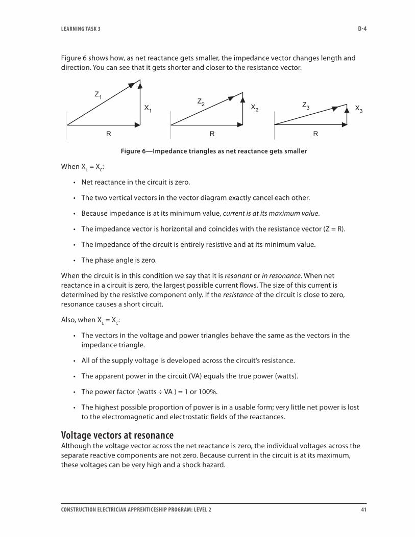
Figure 6 shows how, as net reactance gets smaller, the impedance vector changes length and direction. You can see that it gets shorter and closer to the resistance vector.
Figure 6—Impedance triangles as net reactance gets smaller
When XL = XC:
• Net reactance in the circuit is zero.
• The two vertical vectors in the vector diagram exactly cancel each other.
• Because impedance is at its minimum value, current is at its maximum value.
• The impedance vector is horizontal and coincides with the resistance vector (Z = R).
• The impedance of the circuit is entirely resistive and at its minimum value.
• The phase angle is zero.
When the circuit is in this condition we say that it is resonant or in resonance. When net reactance in a circuit is zero, the largest possible current flows. The size of this current is determined by the resistive component only. If the resistance of the circuit is close to zero, resonance causes a short circuit.
Also, when XL = XC:
• The vectors in the voltage and power triangles behave the same as the vectors in the impedance triangle.
• All of the supply voltage is developed across the circuit’s resistance.
• The apparent power in the circuit (VA) equals the true power (watts).
• The power factor (watts ÷ VA ) = 1 or 100%.
• The highest possible proportion of power is in a usable form; very little net power is lost to the electromagnetic and electrostatic fields of the reactances.
Voltage vectors at resonanceAlthough the voltage vector across the net reactance is zero, the individual voltages across the separate reactive components are not zero. Because current in the circuit is at its maximum, these voltages can be very high and a shock hazard.
LEARNING TASk 3 D-4
42 CONSTRUCTION ELECTRICIAN APPRENTICESHIP PROGRAM: LEVEL 2
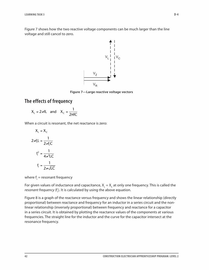
Figure 7 shows how the two reactive voltage components can be much larger than the line voltage and still cancel to zero.
Figure 7—Large reactive voltage vectors
The effects of frequency
X fLL = =2≠ and X1
2πfCC
When a circuit is resonant, the net reactance is zero:
X X
fLf C
fLC
fLC
L C
rr
r
r
=
=
=
=
21
2
14
12
22
≠≠
≠
≠
where fr = resonant frequency
For given values of inductance and capacitance, XL = XC at only one frequency. This is called the resonant frequency (fr). It is calculated by using the above equation.
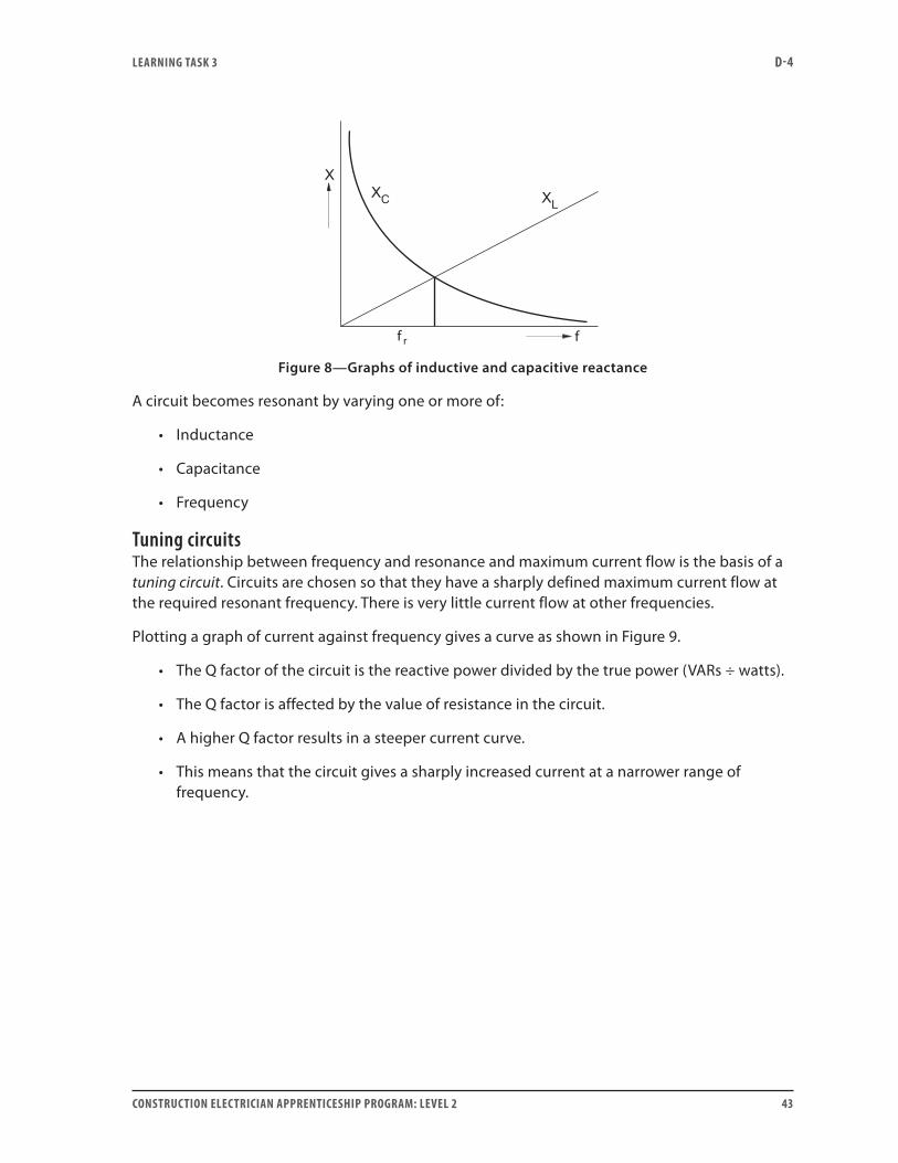
Figure 8 is a graph of the reactance versus frequency and shows the linear relationship (directly proportional) between reactance and frequency for an inductor in a series circuit and the non-linear relationship (inversely proportional) between frequency and reactance for a capacitor in a series circuit. It is obtained by plotting the reactance values of the components at various frequencies. The straight line for the inductor and the curve for the capacitor intersect at the resonance frequency.
LEARNING TASk 3 D-4
CONSTRUCTION ELECTRICIAN APPRENTICESHIP PROGRAM: LEVEL 2 43
f f
Figure 8—Graphs of inductive and capacitive reactance
A circuit becomes resonant by varying one or more of:
• Inductance
• Capacitance
• Frequency
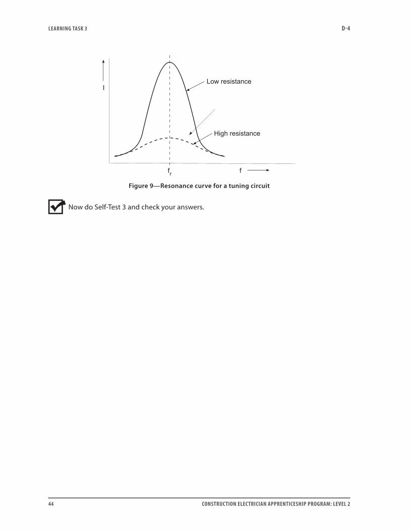
Tuning circuitsThe relationship between frequency and resonance and maximum current flow is the basis of a tuning circuit. Circuits are chosen so that they have a sharply defined maximum current flow at the required resonant frequency. There is very little current flow at other frequencies.
Plotting a graph of current against frequency gives a curve as shown in Figure 9.
• The Q factor of the circuit is the reactive power divided by the true power (VARs ÷ watts).
• The Q factor is affected by the value of resistance in the circuit.
• A higher Q factor results in a steeper current curve.
• This means that the circuit gives a sharply increased current at a narrower range of frequency.
LEARNING TASk 3 D-4
44 CONSTRUCTION ELECTRICIAN APPRENTICESHIP PROGRAM: LEVEL 2
Figure 9—Resonance curve for a tuning circuit
Now do Self-Test 3 and check your answers.

LEARNING TASk 3 D-4
CONSTRUCTION ELECTRICIAN APPRENTICESHIP PROGRAM: LEVEL 2 45
Self-Test 3
1. For each component of a series circuit, the has the same value.
a. line voltage
b. effective current
c. true power
d. effective resistance
2. In an AC series R-L-C circuit, inductive reactance leads the capacitive reactance by 90°.
a. True
b. False
3. Write the Pythagorean Theorem for calculating impedance Z in a series circuit with resistance R, capacitive reactance XC and inductive reactance XL.
4. A circuit with supply voltage of 120 V at 60 Hz contains an inductor coil with inductance 0.2 H and a 40 µF capacitor. What is the net reactance of the circuit? Is it inductive or capacitive?
5. If the current in the circuit in Question 4 is 5 A, what is the reactive power in the circuit?
6. When a circuit is in resonance:
a. Capacitive reactance equals effective resistance.
b. Capacitive reactance equals inductive reactance.
c. Inductive reactance equals circuit impedance.
d. Inductive reactance equals inductive resistance.

LEARNING TASk 3 D-4
46 CONSTRUCTION ELECTRICIAN APPRENTICESHIP PROGRAM: LEVEL 2
7. A circuit that contains both capacitance and inductance tends to cancel out its apparent power.
a. True
b. False
8. What is the value of the power factor in a resonant circuit?
Go to the Answer Key at the end of the Learning Guide to check your answers.
CONSTRUCTION ELECTRICIAN APPRENTICESHIP PROGRAM: LEVEL 2 47
Learning Task 4:
Solve problems involving series AC circuitsBy now, you should have a fairly good working knowledge of resistance, inductance and capacitance, and how these qualities behave in AC circuits. Following are some sample problems dealing with series AC circuits. Study them carefully, and identify if there are any other ways to solve them.
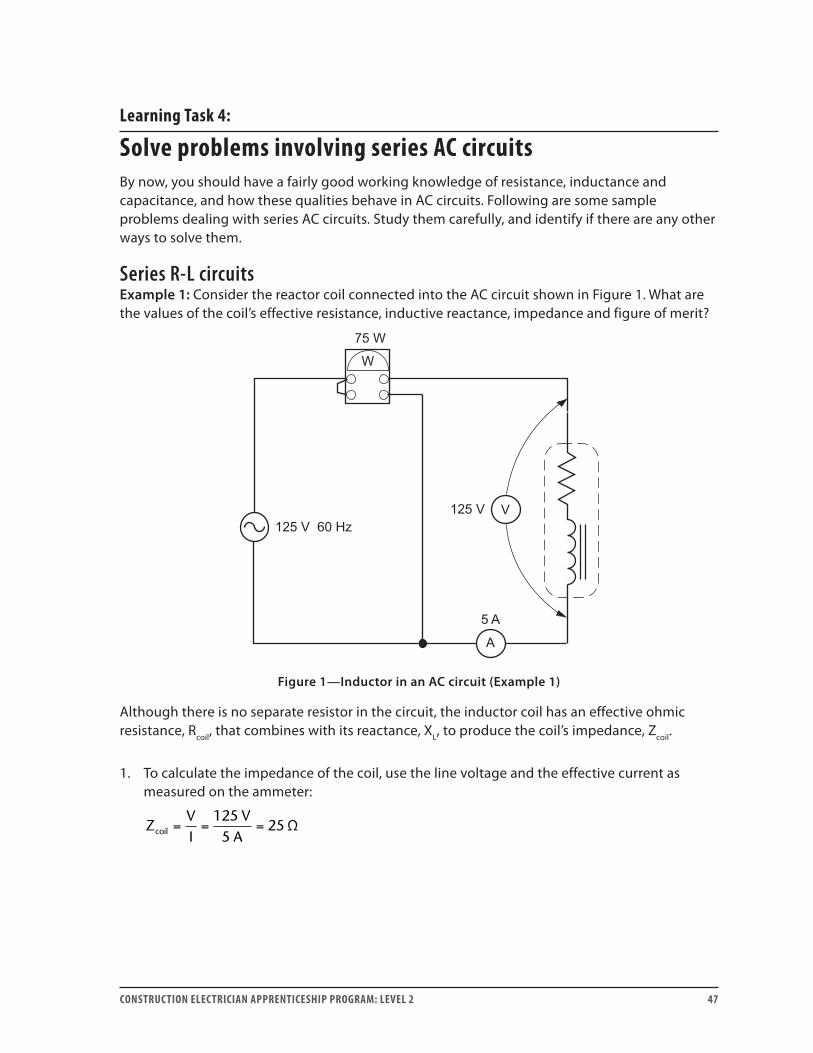
Series R-L circuitsExample 1: Consider the reactor coil connected into the AC circuit shown in Figure 1. What are the values of the coil’s effective resistance, inductive reactance, impedance and figure of merit?
Figure 1—Inductor in an AC circuit (Example 1)
Although there is no separate resistor in the circuit, the inductor coil has an effective ohmic resistance, Rcoil, that combines with its reactance, XL, to produce the coil’s impedance, Zcoil.
1. To calculate the impedance of the coil, use the line voltage and the effective current as measured on the ammeter:
ZVI
VAcoil = = =
1255
25 Ω
LEARNING TASk 4 D-4
48 CONSTRUCTION ELECTRICIAN APPRENTICESHIP PROGRAM: LEVEL 2
2. The power developed and measured in the circuit is due to the effective resistance of the coil (not the inductive reactance):
RWI
WAcoil = = =2 2
755
3 Ω
3. Calculate the inductive reactance of the coil by using the Pythagorean Theorem in the impedance vector triangle:
X Z RL coil coil= − = − =2 2 2 225 3 24 8Ω Ω Ω.
4. QXR
L= = =24 8
38 3
..
ΩΩ
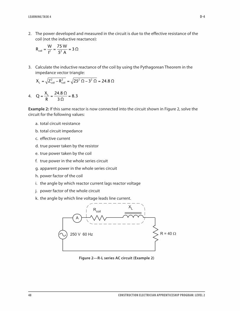
Example 2: If this same reactor is now connected into the circuit shown in Figure 2, solve the circuit for the following values:
a. total circuit resistance
b. total circuit impedance
c. effective current
d. true power taken by the resistor
e. true power taken by the coil
f. true power in the whole series circuit
g. apparent power in the whole series circuit
h. power factor of the coil
i. the angle by which reactor current lags reactor voltage
j. power factor of the whole circuit
k. the angle by which line voltage leads line current.
Figure 2—R-L series AC circuit (Example 2)
LEARNING TASk 4 D-4
CONSTRUCTION ELECTRICIAN APPRENTICESHIP PROGRAM: LEVEL 2 49
The ohmic values (XL, Rcoil and Zcoil) for the inductor coil are the same in this circuit as in Example 1, because the 60 Hz frequency is unchanged.
a. Find the total series circuit resistance by adding individual resistances:
R R R 40 Ω 3 Ω 43 ΩT coil= + = + =
b. Find impedance by combining the resistance and the inductive reactance of the circuit. Inductive reactance of the circuit is all in the reactor coil. Use the formula from the impedance vector triangle:
Z R XT L= + = + =2 2 2 243 24 8 49 7Ω Ω Ω. .
c. The effective current in the circuit would be registered on the ammeter. The line voltage of 250 V is impressed across the total circuit impedance. Find the effective current by using Ohm’s law for the total circuit:
I
VZ
VA A= = = ⊕
25049 7
5 03 5.
.Ω
d. True power developed in the resistor (PR):
P I R 5 A 40 Ω 1000 WR2 2= × = × =
e. True power developed in the coil (Pcoil):
P I R 5 A 3 Ω 75 Wcoil2
coil2= × = × =
f. There are two ways to calculate total true power (PT) for the entire circuit. Either add the values of power developed in the resistor and in the reactor:
P P P 1000 W 75 W 1075 WT R coil= + = + =
or use the current-power formula:
P I R 5 A 43 Ω 1075 WT2
T2= × = × =
g. Total apparent power (VAT) for the circuit is measured in volt-amperes. Calculate it by multiplying the line voltage and effective current:
VA V I 250 V 5 A 1250 VAT = × = × =
h. Calculate the power factor of the coil by using only the ohmic values for the coil in Example 1:
PF
RZcoil
coil
coil
= = =325
0 12ΩΩ
.
LEARNING TASk 4 D-4
50 CONSTRUCTION ELECTRICIAN APPRENTICESHIP PROGRAM: LEVEL 2
i. This PFcoil value is the cosine of the angle 83.1°, which is the phase angle by which the current lags the voltage across the reactor.
j. Calculate the power factor for the entire circuit by using the formula:
PF
WVA
= = =10751250
0 86.
or
PF
RZ
T= = =43
49 70 86
ΩΩ.
.
k. This PF value is the cosine of the angle 30.6°, which is the phase angle by which the line current lags the line voltage. Another way of saying this is that line voltage leads the line current by 30.6°.
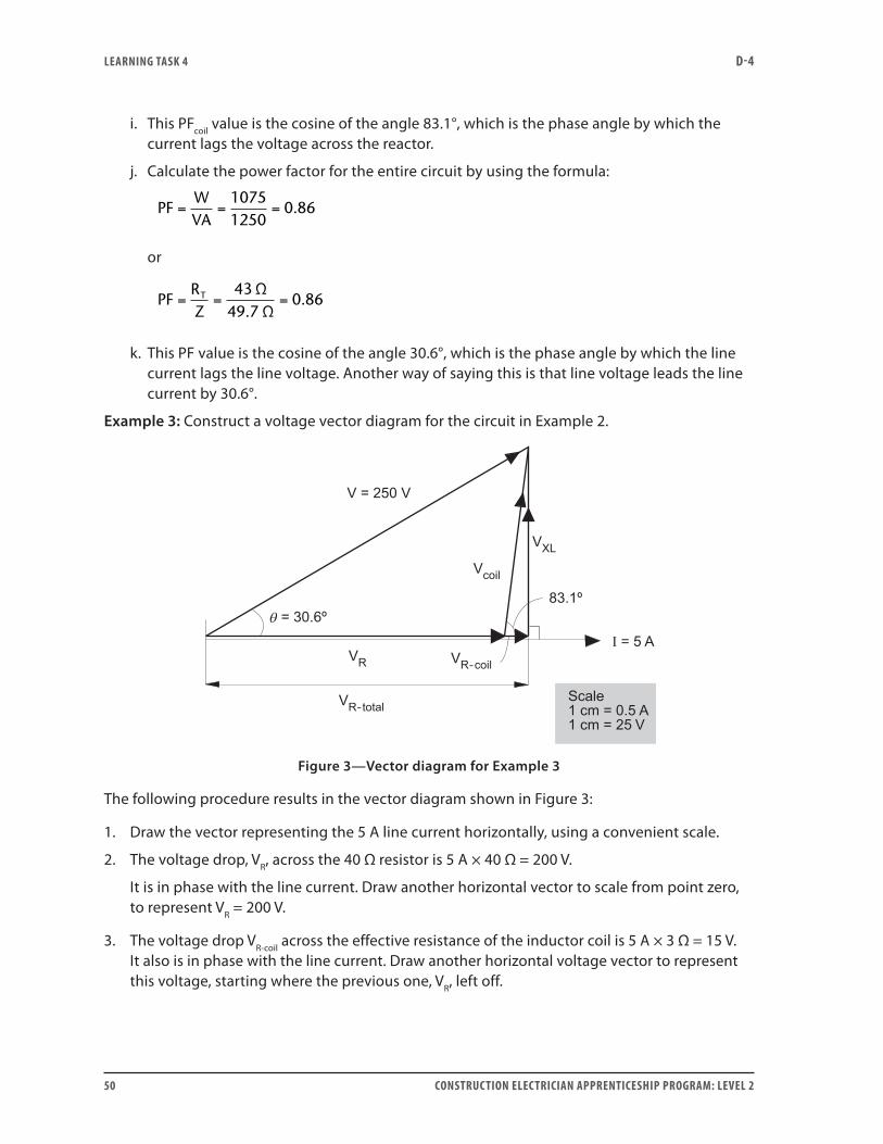
Example 3: Construct a voltage vector diagram for the circuit in Example 2.
Figure 3—Vector diagram for Example 3
The following procedure results in the vector diagram shown in Figure 3:
1. Draw the vector representing the 5 A line current horizontally, using a convenient scale.
2. The voltage drop, VR, across the 40 Ω resistor is 5 A × 40 Ω = 200 V.
It is in phase with the line current. Draw another horizontal vector to scale from point zero, to represent VR = 200 V.
3. The voltage drop VR-coil across the effective resistance of the inductor coil is 5 A × 3 Ω = 15 V. It also is in phase with the line current. Draw another horizontal voltage vector to represent this voltage, starting where the previous one, VR, left off.
LEARNING TASk 4 D-4
CONSTRUCTION ELECTRICIAN APPRENTICESHIP PROGRAM: LEVEL 2 51
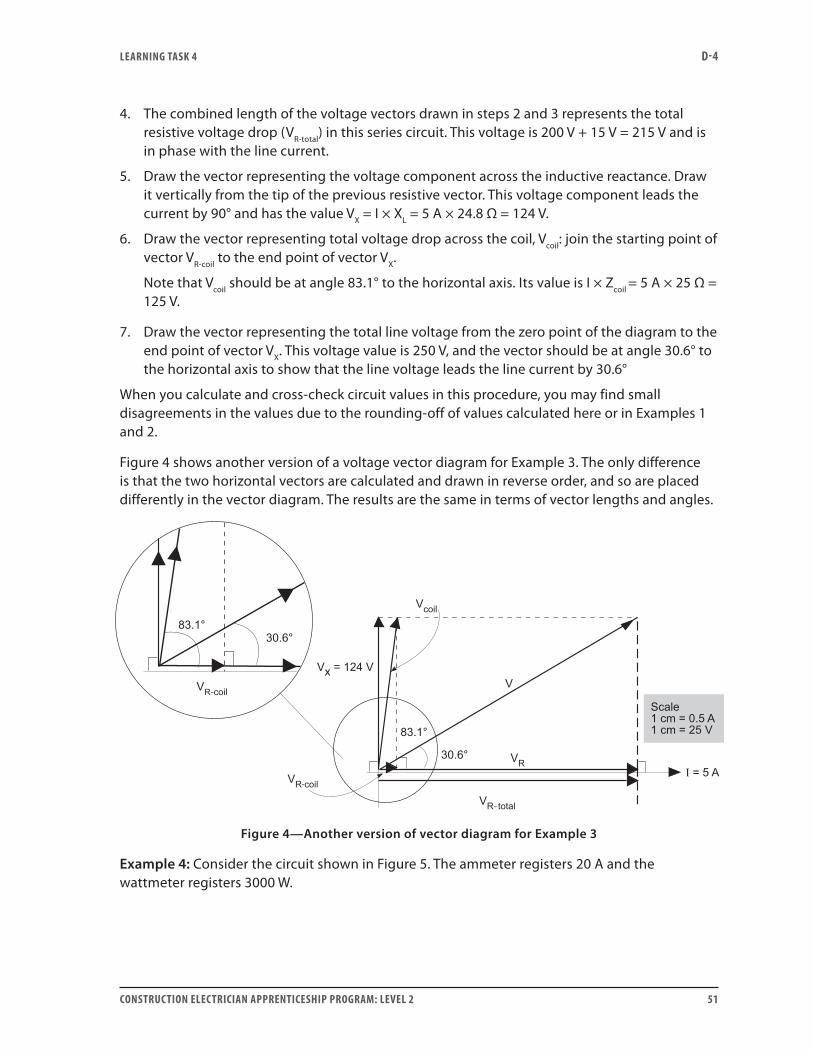
4. The combined length of the voltage vectors drawn in steps 2 and 3 represents the total resistive voltage drop (VR-total) in this series circuit. This voltage is 200 V + 15 V = 215 V and is in phase with the line current.
5. Draw the vector representing the voltage component across the inductive reactance. Draw it vertically from the tip of the previous resistive vector. This voltage component leads the current by 90° and has the value VX = I × XL = 5 A × 24.8 Ω = 124 V.
6. Draw the vector representing total voltage drop across the coil, Vcoil: join the starting point of vector VR-coil to the end point of vector VX.
Note that Vcoil should be at angle 83.1° to the horizontal axis. Its value is I × Zcoil = 5 A × 25 Ω = 125 V.
7. Draw the vector representing the total line voltage from the zero point of the diagram to the end point of vector VX. This voltage value is 250 V, and the vector should be at angle 30.6° to the horizontal axis to show that the line voltage leads the line current by 30.6°
When you calculate and cross-check circuit values in this procedure, you may find small disagreements in the values due to the rounding-off of values calculated here or in Examples 1 and 2.
Figure 4 shows another version of a voltage vector diagram for Example 3. The only difference is that the two horizontal vectors are calculated and drawn in reverse order, and so are placed differently in the vector diagram. The results are the same in terms of vector lengths and angles.
Figure 4—Another version of vector diagram for Example 3
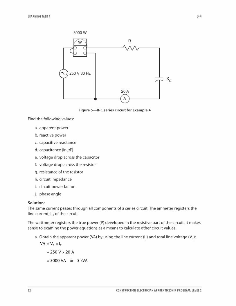
Example 4: Consider the circuit shown in Figure 5. The ammeter registers 20 A and the wattmeter registers 3000 W.
LEARNING TASk 4 D-4
52 CONSTRUCTION ELECTRICIAN APPRENTICESHIP PROGRAM: LEVEL 2
Figure 5—R-C series circuit for Example 4
Find the following values:
a. apparent power
b. reactive power
c. capacitive reactance
d. capacitance (in µF)
e. voltage drop across the capacitor
f. voltage drop across the resistor
g. resistance of the resistor
h. circuit impedance
i. circuit power factor
j. phase angle
Solution: The same current passes through all components of a series circuit. The ammeter registers the line current, IT , of the circuit.
The wattmeter registers the true power (P) developed in the resistive part of the circuit. It makes sense to examine the power equations as a means to calculate other circuit values.
a. Obtain the apparent power (VA) by using the line current (IT) and total line voltage (VT):
VA V I
V A
VA
T T= ×
= ×
=
250 20
5000 or 5 kVA
LEARNING TASk 4 D-4
CONSTRUCTION ELECTRICIAN APPRENTICESHIP PROGRAM: LEVEL 2 53
b. Obtain reactive power (VARs) by using the power vector diagram and the Pythagorean Theorem:
VARs VA W
VARs or kVARs
= −
= −
=
2 2
2 25000 3000
4000 4
c. Reactive power is also expressed as VARs I XC C= ×2 , which allows you to calculate the reactance:
X
VARsICC
= = =2 2
400020
10 Ω
d. From the capacitive reactance formula, calculate capacitance at AC frequency = 60 Hz:
CfX
F
F F
C
= =× × ×
= =
12
12 3 142 60 110
0 000 265 22 265 22
π .
. .
e. Now that you know the reactance of the capacitor and the current through it, use Ohm’s law to calculate the voltage across the capacitor:
V I X 20 10 200 VC C C= × = × =
f. You cannot use Ohm’s law directly to calculate the voltage across the resistive circuit load because you do not yet know its resistance. However, you know the current through the load and the power developed in it, so Watt’s law may be used to solve for the voltage across the resistor.
To calculate VR, use the I × V power equation:
V
PI
VRR
= = =3000
20150
g. Now that you know the current and voltage across the resistor, calculate its resistance using Ohm’s law:
R
VI
R
R
= = =15020
7 5. Ω
Note that you can also use true power and line current to calculate R:
R
PIR
= = =2 2
300020
7 5. Ω
LEARNING TASk 4 D-4
54 CONSTRUCTION ELECTRICIAN APPRENTICESHIP PROGRAM: LEVEL 2
h. Now that you have values for resistance and reactance in the circuit, you can use the Pythagorean Theorem to calculate impedance. There are also other ways to calculate impedance from the known values in the circuit:
Z
VAIT
= = =2 2
500020
12 5.
or
Z R XC= + = + = =2 2 2 27 5 10 156 25 12 5. . . Ω
or
Z
VI
T
T
= = =25020
12 5. Ω
i. The power factor of the circuit may also be calculated in several ways:
PF
RZ
= = = =7 512 5
0 6 60..
. %
or
PF
WVA
= = =30005000
0 6.
or
PF
VV
R
Z
= = =150250
0 6.
j. This power factor is the cosine of the phase angle. The angle whose cosine is 0.6 is 53.1°.
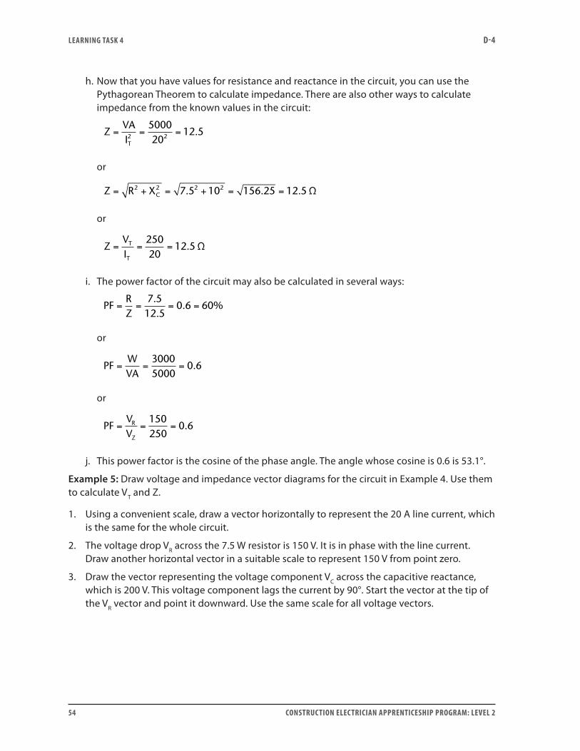
Example 5: Draw voltage and impedance vector diagrams for the circuit in Example 4. Use them to calculate VT and Z.
1. Using a convenient scale, draw a vector horizontally to represent the 20 A line current, which is the same for the whole circuit.
2. The voltage drop VR across the 7.5 W resistor is 150 V. It is in phase with the line current. Draw another horizontal vector in a suitable scale to represent 150 V from point zero.
3. Draw the vector representing the voltage component VC across the capacitive reactance, which is 200 V. This voltage component lags the current by 90°. Start the vector at the tip of the VR vector and point it downward. Use the same scale for all voltage vectors.

LEARNING TASk 4 D-4
CONSTRUCTION ELECTRICIAN APPRENTICESHIP PROGRAM: LEVEL 2 55
4. Draw the vector representing the full line voltage VT by joining the beginning of vector VR (the zero point) to the tip of the vector VC. The length of the hypotenuse in this right-angle triangle is proportional to 250 V and represents the VT vector.
tan200150
cos150
θ
θ
θ
= =
= =
=
−
1 3333
1 3333 53 11
.
tan . . º
VV
÷ cos 53.1
÷
L
V
V
L =
= =
150
150 0 6 250
º
.
The results of these steps are shown in Figure 6.
Figure 6—Constructing a voltage vector diagram for Example 5
5. Construct the impedance triangle in exactly the same way. Start with the current vector as in Step 1.
6. Choose a scale suitable for the resistance, reactance and impedance values in the problem.
7. Construct the resistance vector R in the same direction as the current vector.
8. Construct the reactance vector XC at right angles to it, and lagging.
9. The length of the hypotenuse in this right-angle triangle is proportional to 12.5 Ω and represents the impedance vector, Z.
tan107.5
cosRZ
θ
θ
θ
= =
= =
= =
−
1 3333
1 3333 53 1
7
1
.
tan . . º
..
. cos . º
. . .
5
7 5 53 1
7 5 0 6 12 5
Z
Z =
= =
÷
÷ Ω
LEARNING TASk 4 D-4
56 CONSTRUCTION ELECTRICIAN APPRENTICESHIP PROGRAM: LEVEL 2
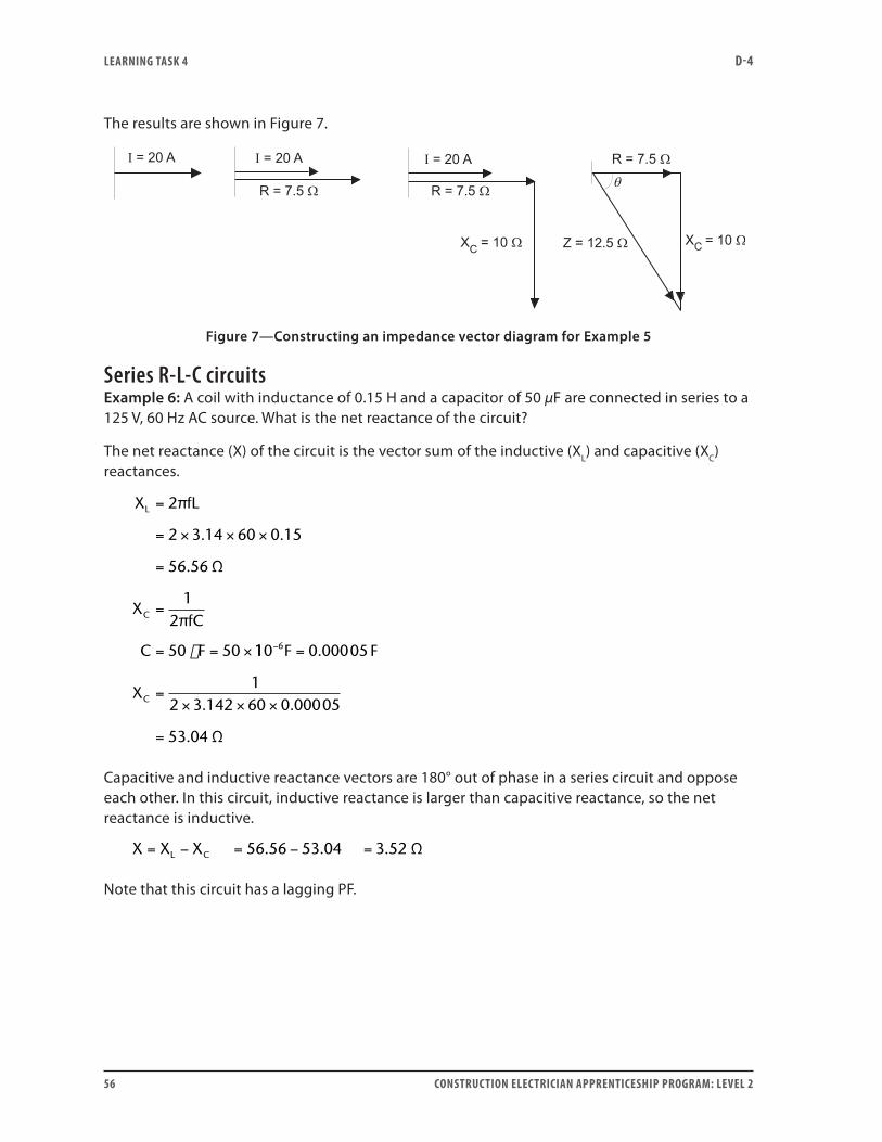
The results are shown in Figure 7.
Figure 7—Constructing an impedance vector diagram for Example 5
Series R-L-C circuitsExample 6: A coil with inductance of 0.15 H and a capacitor of 50 µF are connected in series to a 125 V, 60 Hz AC source. What is the net reactance of the circuit?
The net reactance (X) of the circuit is the vector sum of the inductive (XL) and capacitive (XC) reactances.
X fL
XfC
C F
L
C
=
= × × ×
=
=
= = ×
2
2 3 14 60 0 15
56 56
12
50 50
π
Ω
π
. .
.
110 0 00005
12 3 142 60 0 00005
53 04
6− =
=× × ×
=
F F
XC
.
. .
. Ω
Capacitive and inductive reactance vectors are 180° out of phase in a series circuit and oppose each other. In this circuit, inductive reactance is larger than capacitive reactance, so the net reactance is inductive.
X X X 56.56 53.04 3.52 ΩL C= − = − =
Note that this circuit has a lagging PF.
LEARNING TASk 4 D-4
CONSTRUCTION ELECTRICIAN APPRENTICESHIP PROGRAM: LEVEL 2 57
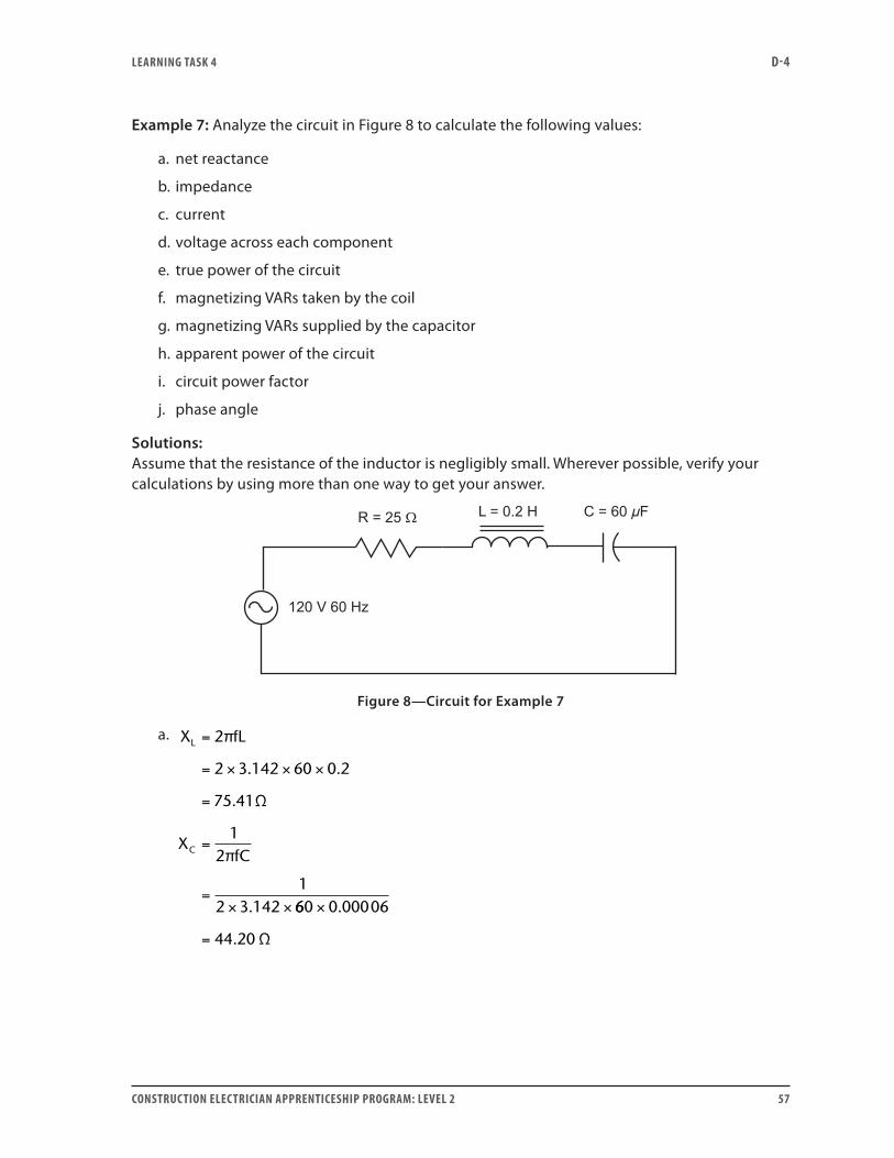
Example 7: Analyze the circuit in Figure 8 to calculate the following values:
a. net reactance
b. impedance
c. current
d. voltage across each component
e. true power of the circuit
f. magnetizing VARs taken by the coil
g. magnetizing VARs supplied by the capacitor
h. apparent power of the circuit
i. circuit power factor
j. phase angle
Solutions:Assume that the resistance of the inductor is negligibly small. Wherever possible, verify your calculations by using more than one way to get your answer.
Figure 8—Circuit for Example 7
a. X fL
XfC
L
C
=
= × × ×
=
=
=× ×
2
2 3 142 60 0 2
75 41
12
12 3 142
π
Ω
π
. .
.
. 660 0 00006
44 20
×
=
.
. Ω
LEARNING TASk 4 D-4
58 CONSTRUCTION ELECTRICIAN APPRENTICESHIP PROGRAM: LEVEL 2
Because XL and XC oppose each other, their net reactance is:
X X XL C= −
= − =75 41 44 20 31 21. . . Ω
This net reactance is inductive.
b. The impedance of the circuit can be obtained by using Ohm’s law if you know the line current and voltage. If not, use the Pythagorean Theorem with resistance and reactance.
Since you are given R = 25 Ω, use the Pythagorean Theorem for impedance (Z):
Z R X= +
= +
=
2 2
2 225 31 21
40
.
Ω
c. Use Ohm’s law to calculate the circuit current from the supply voltage and impedance:
I V Z
A
=
= =
÷
÷120 40 3
d. Use Ohm’s law again to calculate the voltage across each component:
V A V
V A V
V A
R
L
C
= × =
= × =
= × =
3 25 75
3 75 41 226 23
3 44 20 1
Ω
Ω
Ω
. .
. 332 60. V
e. True power is developed only in the resistance of the circuit:
P V I
W
R=
= × =75 3 225
Also,
P I R
W
=
= × × =
2
3 3 25 225
f. Reactive power in the inductance is:
VARs V I
VARs
L L=
= × =226 23 3 678 69. .
g. Reactive power in the capacitance is:
LEARNING TASk 4 D-4
CONSTRUCTION ELECTRICIAN APPRENTICESHIP PROGRAM: LEVEL 2 59
VARs V I
VARs
C C=
= × =132 60 3 397 80. .
h. Use the power equation and the Pythagorean Theorem to calculate the apparent power in the circuit:
VA I Z
VA
=
= × ×
=
2
3 3 40
360
VA W VARs
W VARs VARsL C
= +
= + −
= + −
2 2
2 2
2225 678 69 397
( )
( . .880 359 892) .= VA
(which rounds off to 360 VA)
i. Power factor, PFWVA
= = = =225360
0.625 62.5% lagging.
Note the two other ways to calculate PF:
PFRZ
PFVV
R
T
= = =
= = =
2540
0 625
75120
0 625
.
.
j. PF = cos θ
∴ Phase angle = cos–1 0.625 = 51.3° lagging
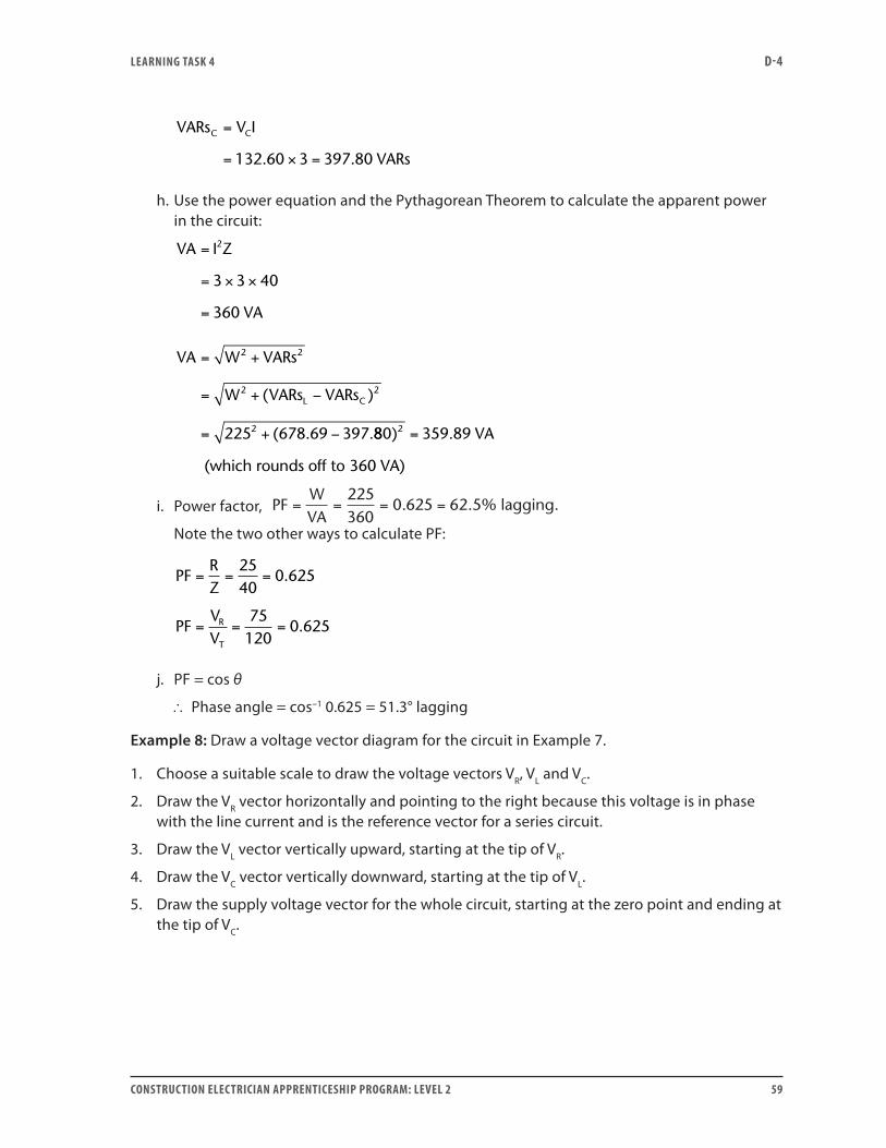
Example 8: Draw a voltage vector diagram for the circuit in Example 7.
1. Choose a suitable scale to draw the voltage vectors VR, VL and VC.
2. Draw the VR vector horizontally and pointing to the right because this voltage is in phase with the line current and is the reference vector for a series circuit.
3. Draw the VL vector vertically upward, starting at the tip of VR.
4. Draw the VC vector vertically downward, starting at the tip of VL.
5. Draw the supply voltage vector for the whole circuit, starting at the zero point and ending at the tip of VC.
LEARNING TASk 4 D-4
60 CONSTRUCTION ELECTRICIAN APPRENTICESHIP PROGRAM: LEVEL 2
Figure 9—Vector diagram for the circuit in Figure 8
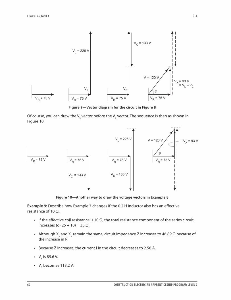
Of course, you can draw the VC vector before the VL vector. The sequence is then as shown in Figure 10.
Figure 10—Another way to draw the voltage vectors in Example 8
Example 9: Describe how Example 7 changes if the 0.2 H inductor also has an effective resistance of 10 Ω.
• If the effective coil resistance is 10 Ω, the total resistance component of the series circuit increases to (25 + 10) = 35 Ω.
• Although XL and XC remain the same, circuit impedance Z increases to 46.89 Ω because of the increase in R.
• Because Z increases, the current I in the circuit decreases to 2.56 A.
• VR is 89.6 V.
• VC becomes 113.2 V.
LEARNING TASk 4 D-4
CONSTRUCTION ELECTRICIAN APPRENTICESHIP PROGRAM: LEVEL 2 61
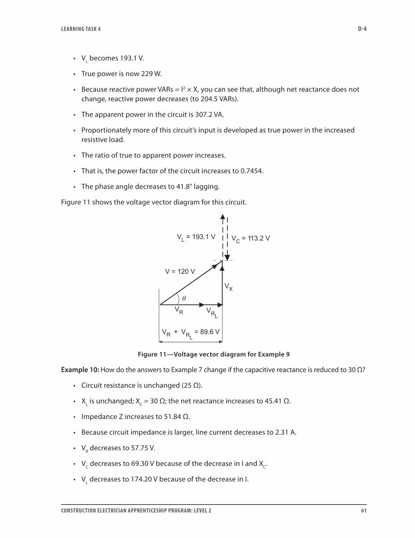
• VL becomes 193.1 V.
• True power is now 229 W.
• Because reactive power VARs = I2 × X, you can see that, although net reactance does not change, reactive power decreases (to 204.5 VARs).
• The apparent power in the circuit is 307.2 VA.
• Proportionately more of this circuit’s input is developed as true power in the increased resistive load.
• The ratio of true to apparent power increases.
• That is, the power factor of the circuit increases to 0.7454.
• The phase angle decreases to 41.8° lagging.
Figure 11 shows the voltage vector diagram for this circuit.
Figure 11—Voltage vector diagram for Example 9
Example 10: How do the answers to Example 7 change if the capacitive reactance is reduced to 30 Ω?
• Circuit resistance is unchanged (25 Ω).
• XL is unchanged; XC = 30 Ω; the net reactance increases to 45.41 Ω.
• Impedance Z increases to 51.84 Ω.
• Because circuit impedance is larger, line current decreases to 2.31 A.
• VR decreases to 57.75 V.
• VC decreases to 69.30 V because of the decrease in I and XC.
• VL decreases to 174.20 V because of the decrease in I.
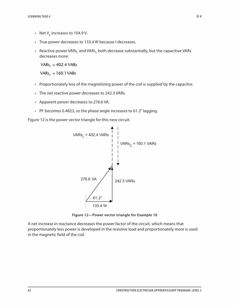
LEARNING TASk 4 D-4
62 CONSTRUCTION ELECTRICIAN APPRENTICESHIP PROGRAM: LEVEL 2
• Net VX increases to 104.9 V.
• True power decreases to 133.4 W because I decreases.
• Reactive power VARsL and VARsC both decrease substantially, but the capacitive VARs decreases more:
VARs VARs
VARs VARs
L
C
=
=
402 4
160 1
.
.
• Proportionately less of the magnetizing power of the coil is supplied by the capacitor.
• The net reactive power decreases to 242.3 VARs.
• Apparent power decreases to 276.6 VA.
• PF becomes 0.4823, so the phase angle increases to 61.2° lagging.
Figure 12 is the power vector triangle for this new circuit.
Figure 12—Power vector triangle for Example 10
A net increase in reactance decreases the power factor of the circuit, which means that proportionately less power is developed in the resistive load and proportionately more is used in the magnetic field of the coil.
LEARNING TASk 4 D-4
CONSTRUCTION ELECTRICIAN APPRENTICESHIP PROGRAM: LEVEL 2 63
Series resonant circuitsExample 11: An AC series R-L-C circuit has L = 0.15 H and C = 50 μF. Find the frequency at which this circuit is in resonance.
fLC
Hz
=
=×
=
12
12 0 15 0 00005
58 11
π
π . .
.
Example 12: A simple series tuning circuit has a 150 μH inductance, a 250 pF capacitance and a 25 Ω resistance. Voltage between the antenna and the ground is 110 μV. Calculate the natural (resonance) frequency of the circuit and the current at resonance.
At resonance XC = XL.
21
2
12
1
2 3 142 1 5 10 2 5 10
1
4 10
≠fLfC
fLC
=
=
=× × × × ×
=
− −
π
π
. . .
22 3 142 3 75 10822
14× × ×=
−. .kHz
At resonance, Z = R (because the reactive components cancel each other). Simply use Ohm’s law to calculate current:
IVR
A= =×
=−110 10
254 4
6
.
Example 13: The circuit in Figure 13 results in the following measurements:
wattmeter: 1100 W voltmeter VL : 201 Vammeter: 5 A voltmeter VC : 100 V
a. Find the circuit’s total voltage VT and the power factor.
b. How much extra capacitance is needed to produce series resonance and how should it be connected?
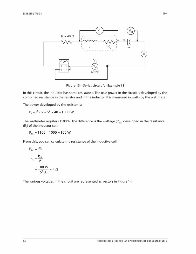
LEARNING TASk 4 D-4
64 CONSTRUCTION ELECTRICIAN APPRENTICESHIP PROGRAM: LEVEL 2
Figure 13—Series circuit for Example 13
In this circuit, the inductor has some resistance. The true power in the circuit is developed by the combined resistance in the resistor and in the inductor. It is measured in watts by the wattmeter.
The power developed by the resistor is:
PR = × = × =I R 5 40 1000 W2 2
The wattmeter registers 1100 W. The difference is the wattage (PR-L) developed in the resistance (RL) of the inductor coil:
P 1100 1000 100 WR-L = − =
From this, you can calculate the resistance of the inductive coil:
P I R
RPI
WA
R L L
LR L
-
-
Ω
=
=
= =
2
2
2
1005
4
The various voltages in the circuit are represented as vectors in Figure 14.
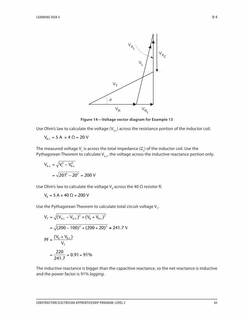
LEARNING TASk 4 D-4
CONSTRUCTION ELECTRICIAN APPRENTICESHIP PROGRAM: LEVEL 2 65
Figure 14—Voltage vector diagram for Example 13
Use Ohm’s law to calculate the voltage (VR-L) across the resistance portion of the inductor coil.
VR L- 5 A 4 Ω 20 V= × =
The measured voltage VL is across the total impedance (ZL) of the inductor coil. Use the Pythagorean Theorem to calculate VX-L, the voltage across the inductive reactance portion only.
V V V
V
X L L R L- -= −
= − =
2 2
2 2201 20 200
Use Ohm’s law to calculate the voltage VR across the 40 Ω resistor R.
V A VR = × =5 40 200Ω
Use the Pythagorean Theorem to calculate total circuit voltage VT.
V V V V VT X L X C R R L= − + +
= − + +
( ) ( )
( ) ( )
- - -2 2
2 2200 100 200 20 ==
=+
= = =
241 7
220241 7
0 91 91
.
( )
.. %
V
PFV V
VR R L
T
-
The inductive reactance is bigger than the capacitive reactance, so the net reactance is inductive and the power factor is 91% lagging.
LEARNING TASk 4 D-4
66 CONSTRUCTION ELECTRICIAN APPRENTICESHIP PROGRAM: LEVEL 2
Find the capacitive reactance in the circuit by using Ohm’s law:
XVI
CfX
fF
CC
C
=
= =
=
=×
= =
1005
20
12
12 20
0 000 132 6 132
Ω
π
π. .66 F
• To produce resonance, the capacitive reactance XC must increase enough to cancel the inductive reactance XL = 40 Ω.
• That is, XC must be increased from 20 Ω to 40 Ω.
• Another 20 Ω capacitive reactance in series with the first will do this.
• Capacitance of a 20 Ω capacitor was previously calculated as 133 µF.
• To put this circuit into resonance, connect another 133 µF capacitor in series with the circuit.
There are other ways to make these calculations. For example, you may use reactance and impedance rather than voltage. Try them yourself or ask your instructor about them.
Now do Self-Test 4 and check your answers.
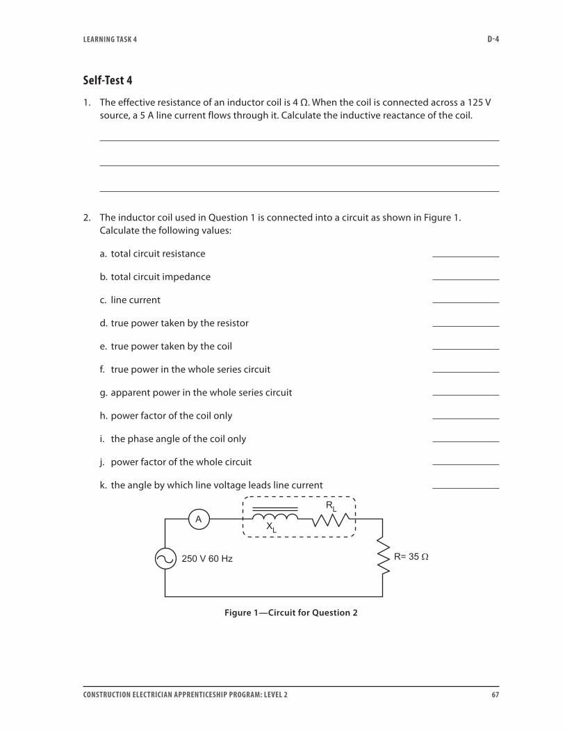
LEARNING TASk 4 D-4
CONSTRUCTION ELECTRICIAN APPRENTICESHIP PROGRAM: LEVEL 2 67
Self-Test 4
1. The effective resistance of an inductor coil is 4 Ω. When the coil is connected across a 125 V source, a 5 A line current flows through it. Calculate the inductive reactance of the coil.
2. The inductor coil used in Question 1 is connected into a circuit as shown in Figure 1. Calculate the following values:
a. total circuit resistance
b. total circuit impedance
c. line current
d. true power taken by the resistor
e. true power taken by the coil
f. true power in the whole series circuit
g. apparent power in the whole series circuit
h. power factor of the coil only
i. the phase angle of the coil only
j. power factor of the whole circuit
k. the angle by which line voltage leads line current
Figure 1—Circuit for Question 2

LEARNING TASk 4 D-4
68 CONSTRUCTION ELECTRICIAN APPRENTICESHIP PROGRAM: LEVEL 2
3. An R-L series AC circuit with frequency of 60 Hz contains a reactor with inductance of 0.2 H. If the circuit’s true power is 115 W and apparent power is 150 VA, calculate the following:
a. line voltage
b. line current
c. voltages across each component
d. circuit impedance
e. circuit resistance
f. circuit reactance
g. power factor
h. phase angle
4. A 300 µF capacitor is connected to a 120 V, 50 Hz supply. Calculate its capacitive reactance.
5. If a 20 Ω resistor is in series with the capacitor in Question 4, what is the impedance of the circuit? (Round your answer to one decimal place.)
6. From the circuit shown in Figure 2, calculate:
a. voltage across the resistance
b. circuit impedance
c. reactance of the capacitor
d. capacitance in microfarads
e. true power
f. reactive power
g. apparent power
h. power factor for the circuit
i. phase angle
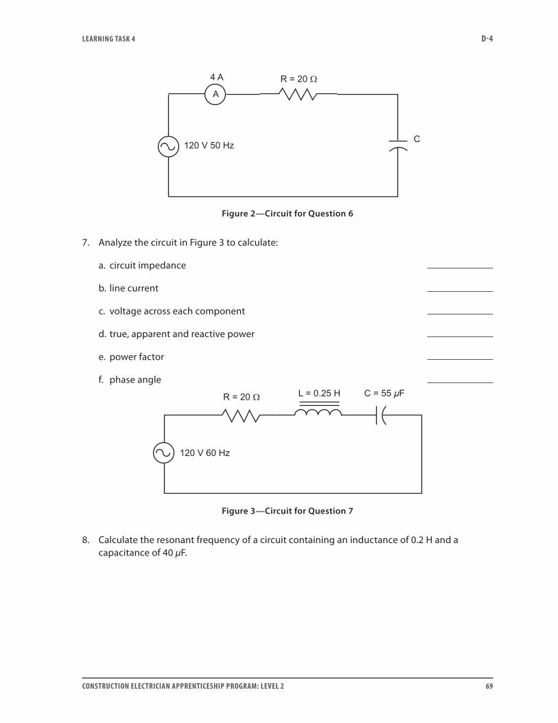
LEARNING TASk 4 D-4
CONSTRUCTION ELECTRICIAN APPRENTICESHIP PROGRAM: LEVEL 2 69
Figure 2—Circuit for Question 6
7. Analyze the circuit in Figure 3 to calculate:
a. circuit impedance
b. line current
c. voltage across each component
d. true, apparent and reactive power
e. power factor
f. phase angle
Figure 3—Circuit for Question 7
8. Calculate the resonant frequency of a circuit containing an inductance of 0.2 H and a capacitance of 40 µF.
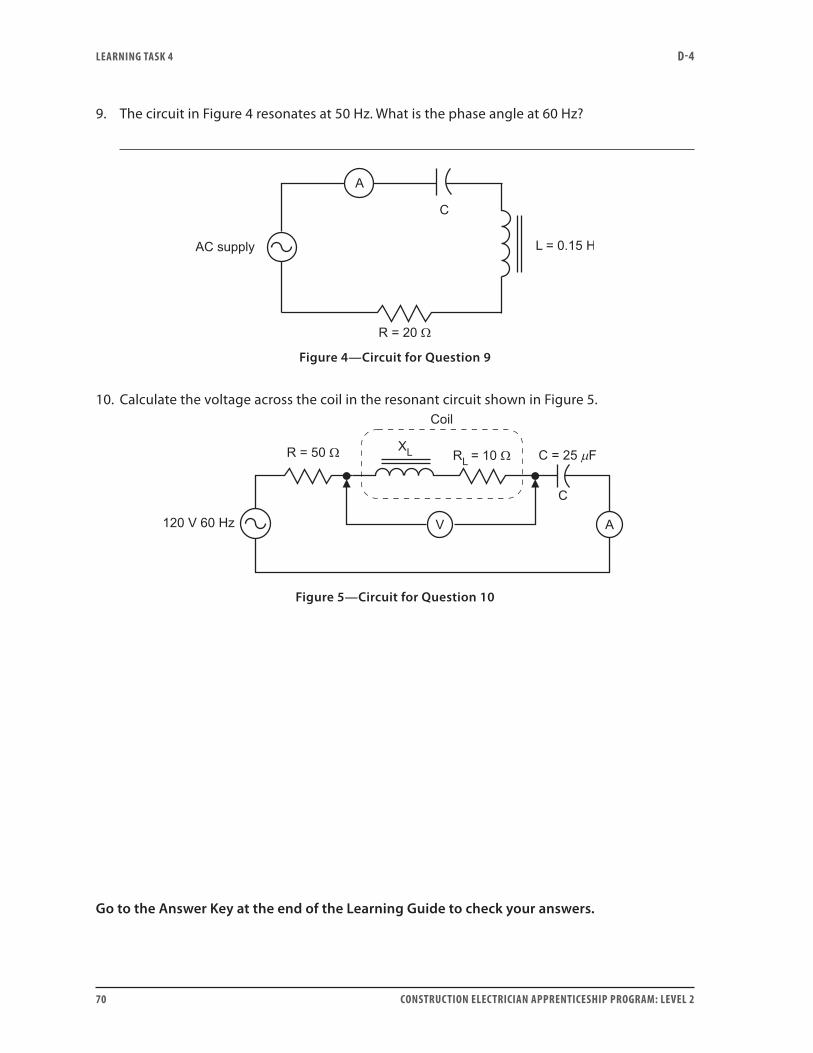
LEARNING TASk 4 D-4
70 CONSTRUCTION ELECTRICIAN APPRENTICESHIP PROGRAM: LEVEL 2
9. The circuit in Figure 4 resonates at 50 Hz. What is the phase angle at 60 Hz?
Figure 4—Circuit for Question 9
10. Calculate the voltage across the coil in the resonant circuit shown in Figure 5.
Figure 5—Circuit for Question 10
Go to the Answer Key at the end of the Learning Guide to check your answers.
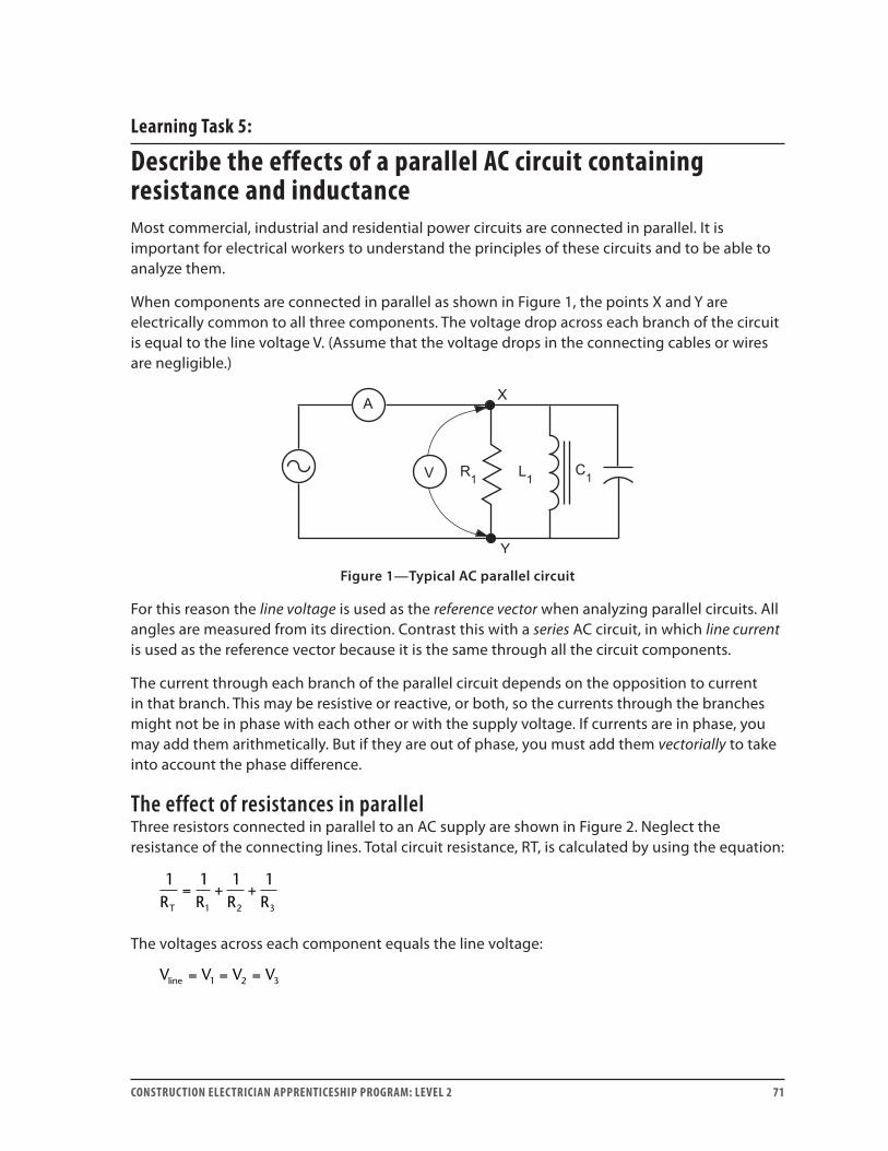
CONSTRUCTION ELECTRICIAN APPRENTICESHIP PROGRAM: LEVEL 2 71
Learning Task 5:
Describe the effects of a parallel AC circuit containing resistance and inductanceMost commercial, industrial and residential power circuits are connected in parallel. It is important for electrical workers to understand the principles of these circuits and to be able to analyze them.
When components are connected in parallel as shown in Figure 1, the points X and Y are electrically common to all three components. The voltage drop across each branch of the circuit is equal to the line voltage V. (Assume that the voltage drops in the connecting cables or wires are negligible.)
Figure 1—Typical AC parallel circuit
For this reason the line voltage is used as the reference vector when analyzing parallel circuits. All angles are measured from its direction. Contrast this with a series AC circuit, in which line current is used as the reference vector because it is the same through all the circuit components.
The current through each branch of the parallel circuit depends on the opposition to current in that branch. This may be resistive or reactive, or both, so the currents through the branches might not be in phase with each other or with the supply voltage. If currents are in phase, you may add them arithmetically. But if they are out of phase, you must add them vectorially to take into account the phase difference.
The effect of resistances in parallelThree resistors connected in parallel to an AC supply are shown in Figure 2. Neglect the resistance of the connecting lines. Total circuit resistance, RT, is calculated by using the equation:
1 1 1 1
1 2 3R R R RT
= + +
The voltages across each component equals the line voltage:
V V V Vline = = =1 2 3
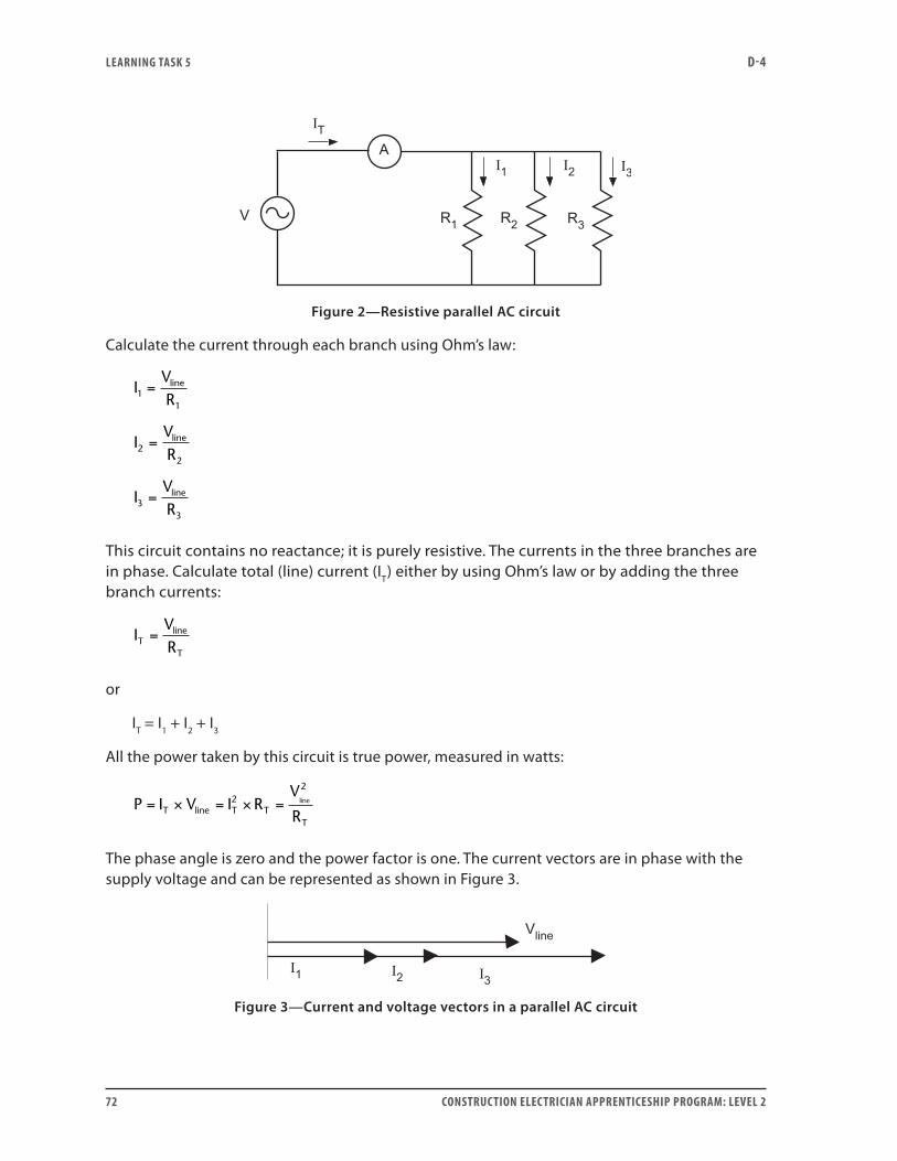
LEARNING TASk 5 D-4
72 CONSTRUCTION ELECTRICIAN APPRENTICESHIP PROGRAM: LEVEL 2
Figure 2—Resistive parallel AC circuit
Calculate the current through each branch using Ohm’s law:
IVR
IVR
IVR
line
line
line
11
22
33
=
=
=
This circuit contains no reactance; it is purely resistive. The currents in the three branches are in phase. Calculate total (line) current (IT) either by using Ohm’s law or by adding the three branch currents:
IVRT
line
T
=
or
IT = I1 + I2 + I3
All the power taken by this circuit is true power, measured in watts:
P I V I RV
RT line T TT
line= × = × =22
The phase angle is zero and the power factor is one. The current vectors are in phase with the supply voltage and can be represented as shown in Figure 3.
Figure 3—Current and voltage vectors in a parallel AC circuit
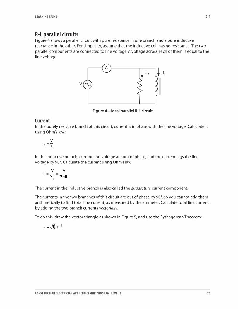
LEARNING TASk 5 D-4
CONSTRUCTION ELECTRICIAN APPRENTICESHIP PROGRAM: LEVEL 2 73
R-L parallel circuitsFigure 4 shows a parallel circuit with pure resistance in one branch and a pure inductive reactance in the other. For simplicity, assume that the inductive coil has no resistance. The two parallel components are connected to line voltage V. Voltage across each of them is equal to the line voltage.
Figure 4—Ideal parallel R-L circuit
CurrentIn the purely resistive branch of this circuit, current is in phase with the line voltage. Calculate it using Ohm’s law:
IVRR =
In the inductive branch, current and voltage are out of phase, and the current lags the line voltage by 90°. Calculate the current using Ohm’s law:
IVX
VfLL
L
= =2π
The current in the inductive branch is also called the quadrature current component.
The currents in the two branches of this circuit are out of phase by 90°, so you cannot add them arithmetically to find total line current, as measured by the ammeter. Calculate total line current by adding the two branch currents vectorially.
To do this, draw the vector triangle as shown in Figure 5, and use the Pythagorean Theorem:
I I IT R L= +2 2
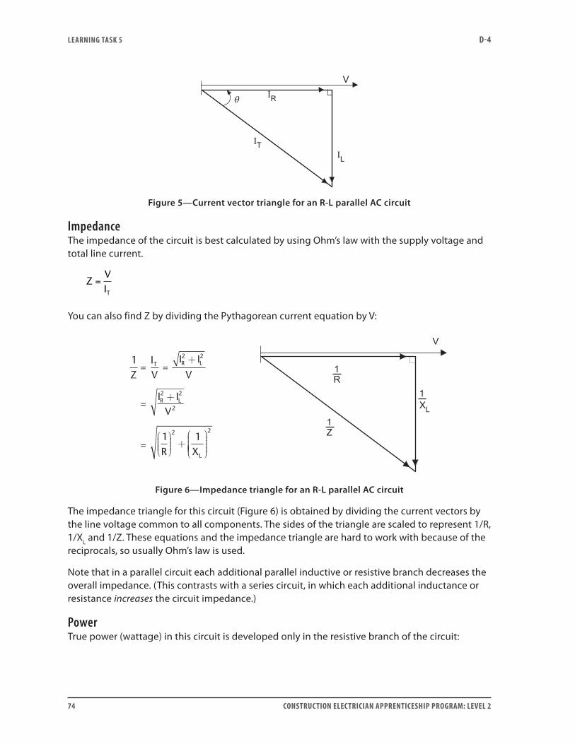
LEARNING TASk 5 D-4
74 CONSTRUCTION ELECTRICIAN APPRENTICESHIP PROGRAM: LEVEL 2
Figure 5—Current vector triangle for an R-L parallel AC circuit
ImpedanceThe impedance of the circuit is best calculated by using Ohm’s law with the supply voltage and total line current.
ZVIT
=
You can also find Z by dividing the Pythagorean current equation by V:
1
1 1
2 2
2 2
2
2
ZIV
I I
V
I IV
R X
T R L
R L
L
+
+
+
2
=
= =
=
Figure 6—Impedance triangle for an R-L parallel AC circuit
The impedance triangle for this circuit (Figure 6) is obtained by dividing the current vectors by the line voltage common to all components. The sides of the triangle are scaled to represent 1/R, 1/XL and 1/Z. These equations and the impedance triangle are hard to work with because of the reciprocals, so usually Ohm’s law is used.
Note that in a parallel circuit each additional parallel inductive or resistive branch decreases the overall impedance. (This contrasts with a series circuit, in which each additional inductance or resistance increases the circuit impedance.)
PowerTrue power (wattage) in this circuit is developed only in the resistive branch of the circuit:
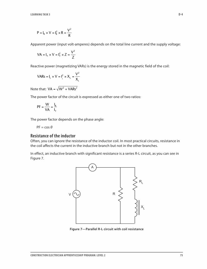
LEARNING TASk 5 D-4
CONSTRUCTION ELECTRICIAN APPRENTICESHIP PROGRAM: LEVEL 2 75
P I V I RVRR R= × = × =2
2
Apparent power (input volt-amperes) depends on the total line current and the supply voltage:
VA I V I ZVZT T= × = × =2
2
Reactive power (magnetizing VARs) is the energy stored in the magnetic field of the coil:
VARs I V I XVXL L
LL
= × = × =22
Note that: VA W VARs= +2 2
The power factor of the circuit is expressed as either one of two ratios:
PFWVA
IIR
T
= =
The power factor depends on the phase angle:
PF = cos θ
Resistance of the inductorOften, you can ignore the resistance of the inductor coil. In most practical circuits, resistance in the coil affects the current in the inductive branch but not in the other branches.
In effect, an inductive branch with significant resistance is a series R-L circuit, as you can see in Figure 7.
Figure 7—Parallel R-L circuit with coil resistance

LEARNING TASk 5 D-4
76 CONSTRUCTION ELECTRICIAN APPRENTICESHIP PROGRAM: LEVEL 2
This branch has impedance (ZL) and its own phase angle. This impedance is the vector sum of the resistance and inductive reactance of the coil:
Z R XL L L= +2 2
The voltages across the resistance and inductance in this branch are 90° out of phase, but the overall voltage across the branch is still equal to the line voltage. The total line current vector is the vector sum of the currents of the resistive and inductive branches.
Analysis of this type of circuit is sometimes complicated, and is discussed in Learning Task 8.
Now do Self-Test 5 and check your answers.

LEARNING TASk 5 D-4
CONSTRUCTION ELECTRICIAN APPRENTICESHIP PROGRAM: LEVEL 2 77
Self-Test 5
1. In a purely inductive parallel circuit, current (leads, lags) the voltage by 90°.
2. In a purely inductive AC parallel circuit, when instantaneous current and voltage are both negative, the instantaneous power value is:
a. positive
b. negative
3. In an AC parallel R-L circuit, why don’t you add the currents through the resistor and inductor arithmetically?
4. Three resistors are connected in parallel across 120 V, 60 Hz. The resulting line current is 22 A. Resistance R2 is twice the value of R1. Resistance R3 is three times the value of R1. Calculate resistance and current in each branch of the circuit.
5. What is the phase relationship between the currents through the resistor and inductor in a parallel R-L circuit?
6. What type of power is measured in VA, and with which part of an R-L circuit is it associated?

LEARNING TASk 5 D-4
78 CONSTRUCTION ELECTRICIAN APPRENTICESHIP PROGRAM: LEVEL 2
7. If you know the values of true power and apparent power in an R-L parallel circuit, how do you calculate reactive power?
Go to the Answer Key at the end of the Learning Guide to check your answers.
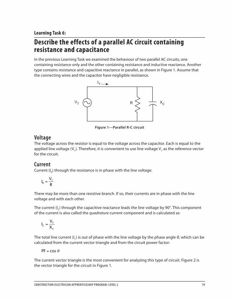
CONSTRUCTION ELECTRICIAN APPRENTICESHIP PROGRAM: LEVEL 2 79
Learning Task 6:
Describe the effects of a parallel AC circuit containing resistance and capacitanceIn the previous Learning Task we examined the behaviour of two parallel AC circuits, one containing resistance only and the other containing resistance and inductive reactance. Another type contains resistance and capacitive reactance in parallel, as shown in Figure 1. Assume that the connecting wires and the capacitor have negligible resistance.
Figure 1—Parallel R-C circuit
VoltageThe voltage across the resistor is equal to the voltage across the capacitor. Each is equal to the applied line voltage (VT). Therefore, it is convenient to use line voltage VT as the reference vector for the circuit.
CurrentCurrent (IR) through the resistance is in phase with the line voltage.
IVRR
T=
There may be more than one resistive branch. If so, their currents are in phase with the line voltage and with each other.
The current (IC) through the capacitive reactance leads the line voltage by 90°. This component of the current is also called the quadrature current component and is calculated as:
IVXC
T
C
=
The total line current (IT) is out of phase with the line voltage by the phase angle θ, which can be calculated from the current vector triangle and from the circuit power factor:
PF = cos θ
The current vector triangle is the most convenient for analyzing this type of circuit. Figure 2 is the vector triangle for the circuit in Figure 1.
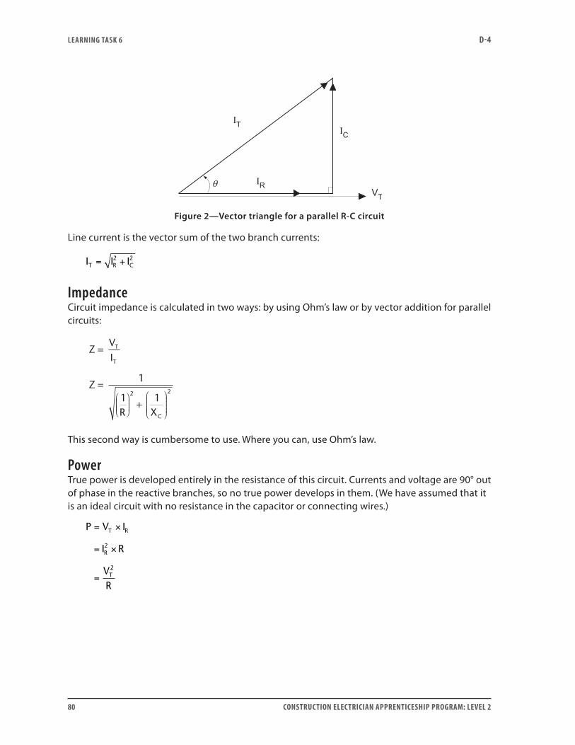
LEARNING TASk 6 D-4
80 CONSTRUCTION ELECTRICIAN APPRENTICESHIP PROGRAM: LEVEL 2
Figure 2—Vector triangle for a parallel R-C circuit
Line current is the vector sum of the two branch currents:
I I IT R C= +2 2
ImpedanceCircuit impedance is calculated in two ways: by using Ohm’s law or by vector addition for parallel circuits:
ZVI
Z
R X
T
T
C
=
= +
1
1 12 2
This second way is cumbersome to use. Where you can, use Ohm’s law.
PowerTrue power is developed entirely in the resistance of this circuit. Currents and voltage are 90° out of phase in the reactive branches, so no true power develops in them. (We have assumed that it is an ideal circuit with no resistance in the capacitor or connecting wires.)
P V I
I R
VR
T R
R
T
= ×
= ×
=
2
2
LEARNING TASk 6 D-4
CONSTRUCTION ELECTRICIAN APPRENTICESHIP PROGRAM: LEVEL 2 81
Reactive power is used in the electrostatic field of the capacitor and is calculated as follows:
VARs V I
I X
VX
T C
C C
T
C
= ×
= ×
=
2
2
Apparent power is calculated by using the line current (IT) and line voltage (VT), or by using the power triangle:
VA V IT T= ×
Power factor and phase angleThe power factor of the circuit is the ratio of true to apparent power. It is also the ratio of in-phase current to line current:
PFWVA
IIR
T
= =
Total line current (IT) is out of phase with the line voltage by the phase angle θ. As before, you can calculate this angle from the current vector triangle or from the circuit power factor:
PF = cos θ
Now do Self-Test 6 and check your answers.

LEARNING TASk 6 D-4
82 CONSTRUCTION ELECTRICIAN APPRENTICESHIP PROGRAM: LEVEL 2
Self-Test 6
1. In a purely capacitive parallel circuit, current (leads, lags) the voltage by 90°.
2. In a purely capacitive AC parallel circuit, when instantaneous current is negative and instantaneous voltage is positive, the instantaneous power value is:
a. positive
b. negative
3. Three capacitors have reactances of 10 Ω, 20 Ω and 30 Ω. Find the net reactance of the three capacitors if they are connected in parallel.
4. What is the phase relationship between the currents through the resistor and the capacitor when they are connected in parallel?
5. With which part of an R-C circuit is VA power associated?
6. If you know the apparent power and the reactive power in an R-C parallel circuit, how do you calculate true power?
Go to the Answer Key at the end of the Learning Guide to check your answers.
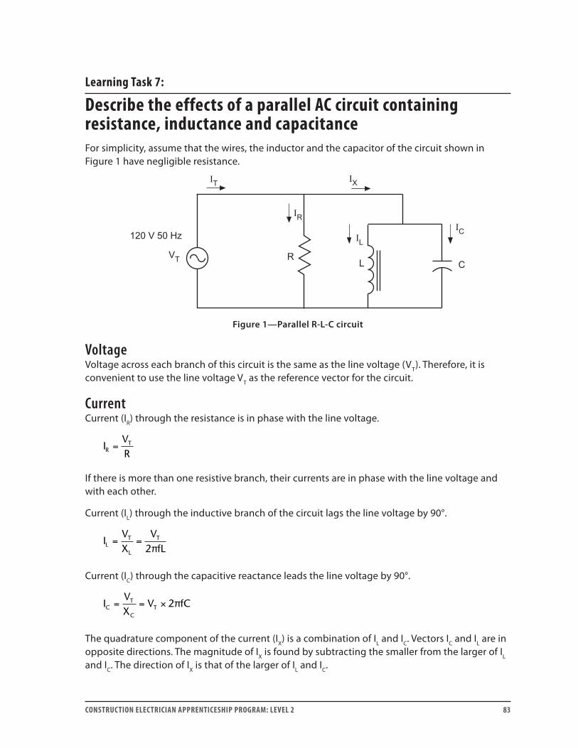
CONSTRUCTION ELECTRICIAN APPRENTICESHIP PROGRAM: LEVEL 2 83
Learning Task 7:
Describe the effects of a parallel AC circuit containing resistance, inductance and capacitanceFor simplicity, assume that the wires, the inductor and the capacitor of the circuit shown in Figure 1 have negligible resistance.
Figure 1—Parallel R-L-C circuit
VoltageVoltage across each branch of this circuit is the same as the line voltage (VT). Therefore, it is convenient to use the line voltage VT as the reference vector for the circuit.
CurrentCurrent (IR) through the resistance is in phase with the line voltage.
IVRR
T=
If there is more than one resistive branch, their currents are in phase with the line voltage and with each other.
Current (IL) through the inductive branch of the circuit lags the line voltage by 90°.
IVX
VfLL
T
L
T= =2π
Current (IC) through the capacitive reactance leads the line voltage by 90°.
IVX
V fCCT
CT= = × 2π
The quadrature component of the current (IX) is a combination of IL and IC. Vectors IC and IL are in opposite directions. The magnitude of IX is found by subtracting the smaller from the larger of IL and IC. The direction of IX is that of the larger of IL and IC.
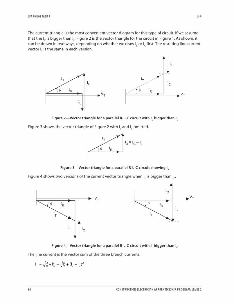
LEARNING TASk 7 D-4
84 CONSTRUCTION ELECTRICIAN APPRENTICESHIP PROGRAM: LEVEL 2
The current triangle is the most convenient vector diagram for this type of circuit. If we assume that the IC is bigger than IL, Figure 2 is the vector triangle for the circuit in Figure 1. As shown, it can be drawn in two ways, depending on whether we draw IL or IC first. The resulting line current vector IT is the same in each version.
Figure 2—Vector triangle for a parallel R-L-C circuit with IC bigger than IL
Figure 3 shows the vector triangle of Figure 2 with IL and IC omitted.
Figure 3—Vector triangle for a parallel R-L-C circuit showing IX
Figure 4 shows two versions of the current vector triangle when IL is bigger than IC.
Figure 4—Vector triangle for a parallel R-L-C circuit with IL bigger than IC
The line current is the vector sum of the three branch currents:
I I I I I IT R X R L C= + = + −2 2 2 2( )
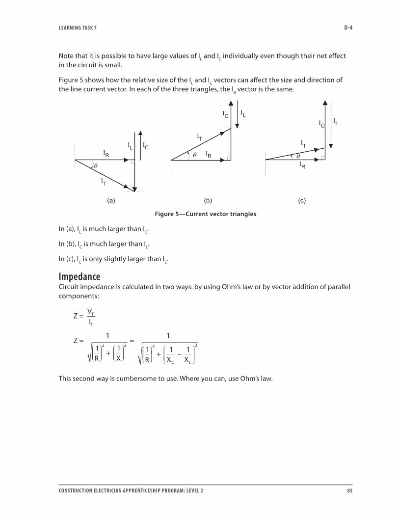
LEARNING TASk 7 D-4
CONSTRUCTION ELECTRICIAN APPRENTICESHIP PROGRAM: LEVEL 2 85
Note that it is possible to have large values of IL and IC individually even though their net effect in the circuit is small.
Figure 5 shows how the relative size of the IL and IC vectors can affect the size and direction of the line current vector. In each of the three triangles, the IR vector is the same.
Figure 5—Current vector triangles
In (a), IL is much larger than IC.
In (b), IC is much larger than IL.
In (c), IC is only slightly larger than IL.
ImpedanceCircuit impedance is calculated in two ways: by using Ohm’s law or by vector addition of parallel components:
ZVI
Z
R X R
T
T
=
= +
=
1
1 1
1
12 2
+ −
2 21 1
X XC L
This second way is cumbersome to use. Where you can, use Ohm’s law.
LEARNING TASk 7 D-4
86 CONSTRUCTION ELECTRICIAN APPRENTICESHIP PROGRAM: LEVEL 2
Power and phase angleTrue power is developed entirely in the resistance of this circuit. Currents and voltage are 90° out of phase in the reactive branches, so no true power develops in them. (We have assumed that it is an ideal circuit with no resistance in the coil or wires.)
P V I
I R
VR
T R
R
T
= ×
= ×
=
2
2
As you saw in series R-L-C circuits, the coil uses some energy in its magnetic field, some or all of which is supplied by the capacitor from energy stored in its electric field:
VARs V I
I X
VX
L T L
L L
T
L
= ×
= ×
=
2
2
and
VARs V I
I X
VX
C T C
C C
T
C
= ×
= ×
=
2
2
Net magnetizing energy supplied by the line is the difference between VARsL and VARsC.
Apparent power is calculated by using the line current (IT) and line voltage (VT), or by using the power triangle. The power factor of the circuit is the ratio of true to apparent power. It is also the ratio of in-phase current to line current:
PFWVA
IIR
T
= =
Total line current (IT) is out of phase with the line voltage by the phase angle θ. As before, you can calculate this angle from the current vector triangle or from the circuit power factor:
PF = cos θ
Whether the phase angle is leading or lagging depends on the relative sizes of the inductive and capacitive reactances in the circuit. If current in the capacitive branch is greater (smaller capacitive reactance), then the phase angle is leading. If current in the inductive branch is greater (smaller inductive reactance), then the phase angle is lagging.
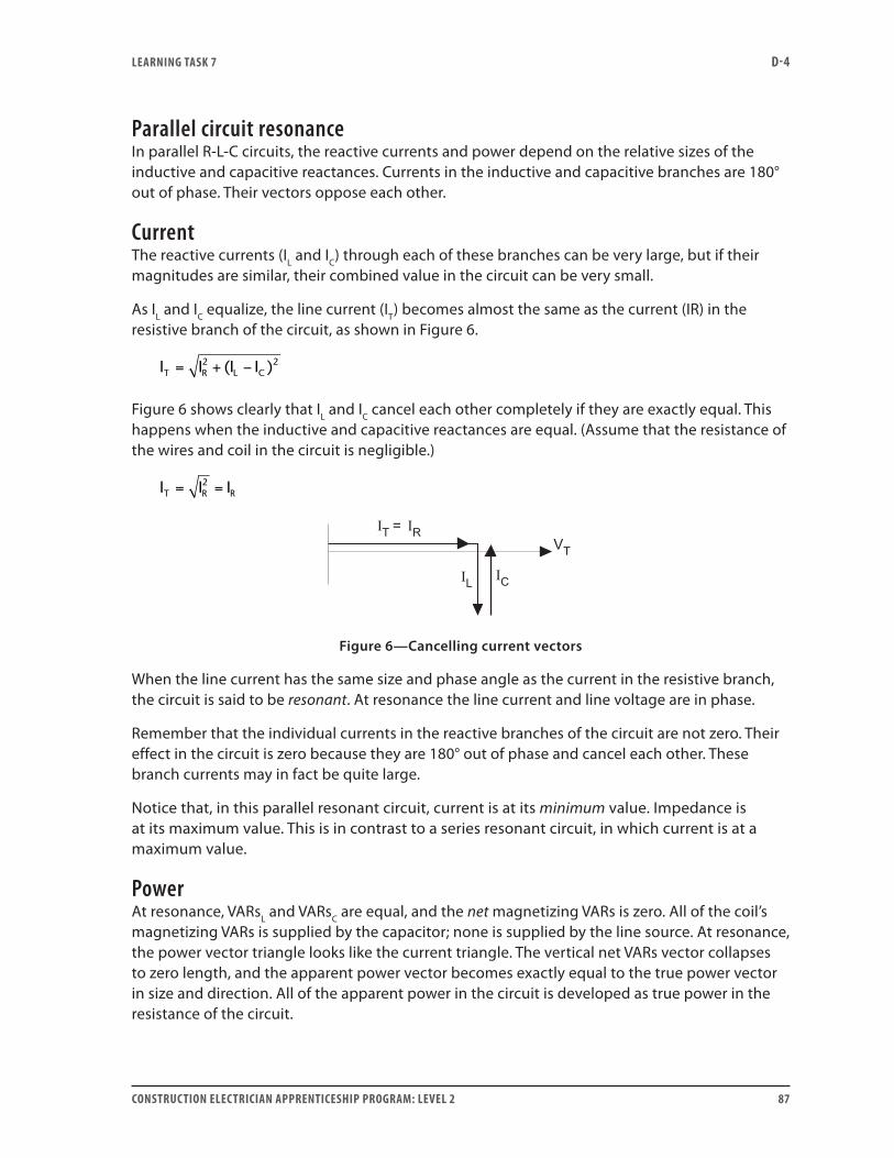
LEARNING TASk 7 D-4
CONSTRUCTION ELECTRICIAN APPRENTICESHIP PROGRAM: LEVEL 2 87
Parallel circuit resonanceIn parallel R-L-C circuits, the reactive currents and power depend on the relative sizes of the inductive and capacitive reactances. Currents in the inductive and capacitive branches are 180° out of phase. Their vectors oppose each other.
CurrentThe reactive currents (IL and IC) through each of these branches can be very large, but if their magnitudes are similar, their combined value in the circuit can be very small.
As IL and IC equalize, the line current (IT) becomes almost the same as the current (IR) in the resistive branch of the circuit, as shown in Figure 6.
I I I IT R L C= + −2 2( )
Figure 6 shows clearly that IL and IC cancel each other completely if they are exactly equal. This happens when the inductive and capacitive reactances are equal. (Assume that the resistance of the wires and coil in the circuit is negligible.)
I I IT R R= =2
Figure 6—Cancelling current vectors
When the line current has the same size and phase angle as the current in the resistive branch, the circuit is said to be resonant. At resonance the line current and line voltage are in phase.
Remember that the individual currents in the reactive branches of the circuit are not zero. Their effect in the circuit is zero because they are 180° out of phase and cancel each other. These branch currents may in fact be quite large.
Notice that, in this parallel resonant circuit, current is at its minimum value. Impedance is at its maximum value. This is in contrast to a series resonant circuit, in which current is at a maximum value.
PowerAt resonance, VARsL and VARsC are equal, and the net magnetizing VARs is zero. All of the coil’s magnetizing VARs is supplied by the capacitor; none is supplied by the line source. At resonance, the power vector triangle looks like the current triangle. The vertical net VARs vector collapses to zero length, and the apparent power vector becomes exactly equal to the true power vector in size and direction. All of the apparent power in the circuit is developed as true power in the resistance of the circuit.
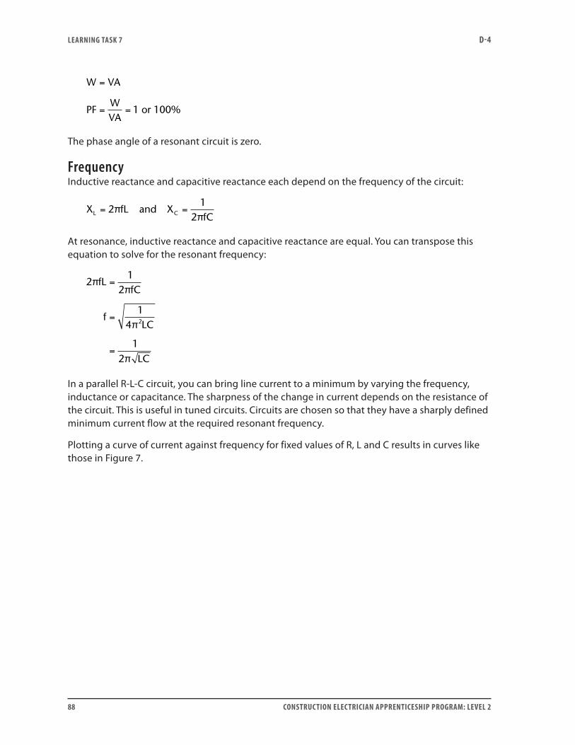
LEARNING TASk 7 D-4
88 CONSTRUCTION ELECTRICIAN APPRENTICESHIP PROGRAM: LEVEL 2
W VA
PFWVA
=
= = 1 or 100%
The phase angle of a resonant circuit is zero.
FrequencyInductive reactance and capacitive reactance each depend on the frequency of the circuit:
X fL and XfCL C= =2
12
ππ
At resonance, inductive reactance and capacitive reactance are equal. You can transpose this equation to solve for the resonant frequency:
21
2
14
12
2
ππ
π
π
fLfC
fLC
LC
=
=
=
In a parallel R-L-C circuit, you can bring line current to a minimum by varying the frequency, inductance or capacitance. The sharpness of the change in current depends on the resistance of the circuit. This is useful in tuned circuits. Circuits are chosen so that they have a sharply defined minimum current flow at the required resonant frequency.
Plotting a curve of current against frequency for fixed values of R, L and C results in curves like those in Figure 7.
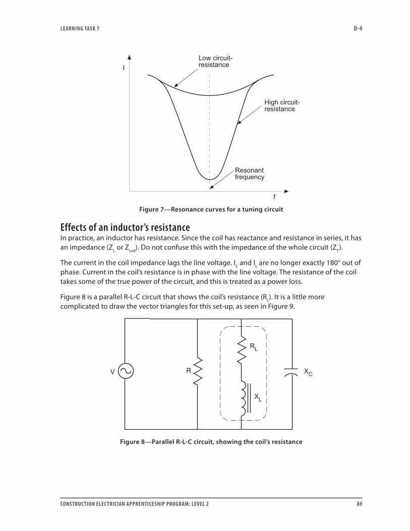
LEARNING TASk 7 D-4
CONSTRUCTION ELECTRICIAN APPRENTICESHIP PROGRAM: LEVEL 2 89
Figure 7—Resonance curves for a tuning circuit
Effects of an inductor’s resistanceIn practice, an inductor has resistance. Since the coil has reactance and resistance in series, it has an impedance (ZL or Zcoil). Do not confuse this with the impedance of the whole circuit (ZT).
The current in the coil impedance lags the line voltage. IC and IL are no longer exactly 180° out of phase. Current in the coil’s resistance is in phase with the line voltage. The resistance of the coil takes some of the true power of the circuit, and this is treated as a power loss.
Figure 8 is a parallel R-L-C circuit that shows the coil’s resistance (RL). It is a little more complicated to draw the vector triangles for this set-up, as seen in Figure 9.
Figure 8—Parallel R-L-C circuit, showing the coil’s resistance
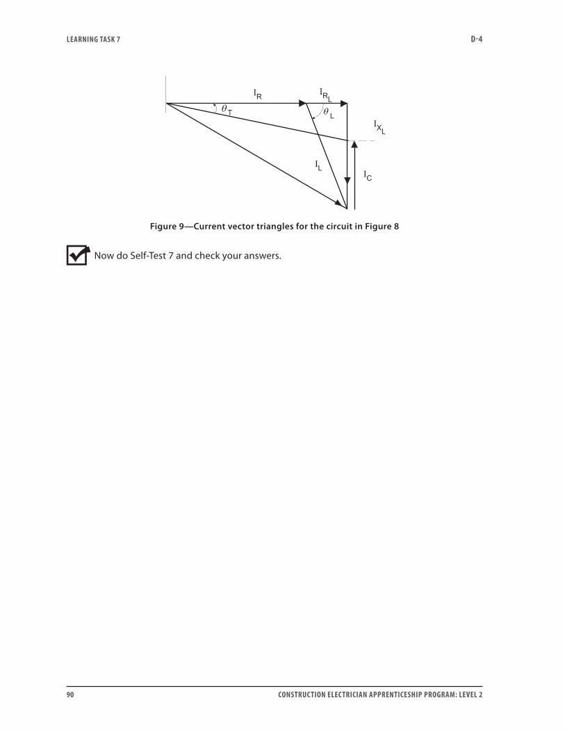
LEARNING TASk 7 D-4
90 CONSTRUCTION ELECTRICIAN APPRENTICESHIP PROGRAM: LEVEL 2
Figure 9—Current vector triangles for the circuit in Figure 8
Now do Self-Test 7 and check your answers.

LEARNING TASk 7 D-4
CONSTRUCTION ELECTRICIAN APPRENTICESHIP PROGRAM: LEVEL 2 91
Self-Test 7
1. Why is line voltage used as the reference vector in an R-L-C parallel circuit?
2. Where is true power developed in an R-L-C parallel circuit?
3. What is the phase angle between the current vectors in the reactive branches of an R-L-C parallel circuit?
4. Net VARs in an R-L-C parallel circuit is entirely developed in the coil of the inductor.
a. True
b. False
5. If the current through the capacitive branch is larger than the current through the inductive branch, the phase angle of an R-L-C parallel circuit is:
a. leading
b. lagging
6. Which of the following would reduce the value of line current in an R-L-C parallel circuit that has a lagging PF?
a. Decrease the value of resistance (R).
b. Decrease the value of inductance (L).
c. Decrease the value of capacitance (C).
d. Increase the value of capacitance (C).

LEARNING TASk 7 D-4
92 CONSTRUCTION ELECTRICIAN APPRENTICESHIP PROGRAM: LEVEL 2
7. What factor often prevents the currents in the capacitive and inductive branches from being exactly out of phase?
Go to the Answer Key at the end of the Learning Guide to check your answers.
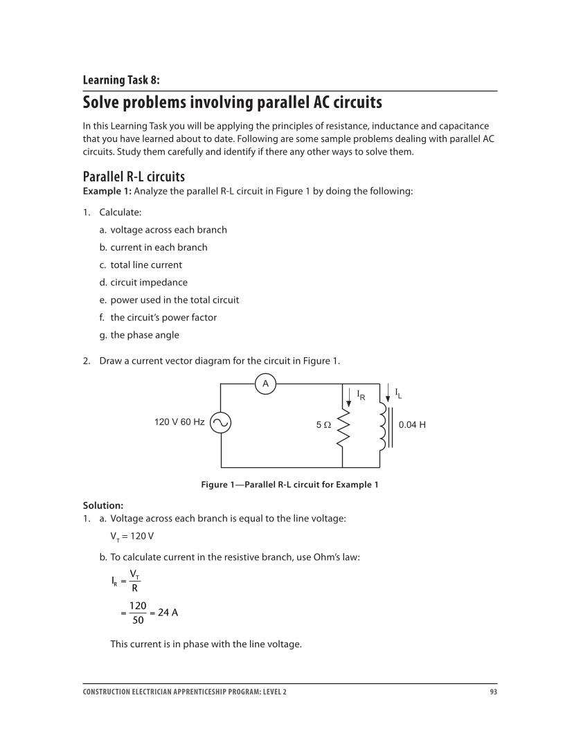
CONSTRUCTION ELECTRICIAN APPRENTICESHIP PROGRAM: LEVEL 2 93
Learning Task 8:
Solve problems involving parallel AC circuitsIn this Learning Task you will be applying the principles of resistance, inductance and capacitance that you have learned about to date. Following are some sample problems dealing with parallel AC circuits. Study them carefully and identify if there any other ways to solve them.
Parallel R-L circuitsExample 1: Analyze the parallel R-L circuit in Figure 1 by doing the following:
1. Calculate:
a. voltage across each branch
b. current in each branch
c. total line current
d. circuit impedance
e. power used in the total circuit
f. the circuit’s power factor
g. the phase angle
2. Draw a current vector diagram for the circuit in Figure 1.
Figure 1—Parallel R-L circuit for Example 1
Solution:1. a. Voltage across each branch is equal to the line voltage:
VT = 120 V
b. To calculate current in the resistive branch, use Ohm’s law:
IVR
A
RT=
= =12050
24
This current is in phase with the line voltage.
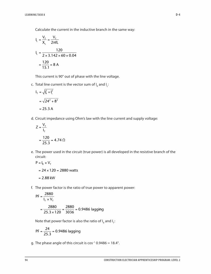
LEARNING TASk 8 D-4
94 CONSTRUCTION ELECTRICIAN APPRENTICESHIP PROGRAM: LEVEL 2
Calculate the current in the inductive branch in the same way:
IVX
VfL
I
A
LT
L
T
L
= =
=× × ×
= =
2
1202 3 142 60 0 04
12015 1
8
π
. .
.
This current is 90° out of phase with the line voltage.
c. Total line current is the vector sum of IR and IL:
I I I
A
T R L= +
= +
=
2 2
2 224 8
25 3.
d. Circuit impedance using Ohm’s law with the line current and supply voltage:
ZVI
T
T
=
= =12025 3
4 74.
. Ω
e. The power used in the circuit (true power) is all developed in the resistive branch of the circuit:
P I VR T= ×
= × =
=
24 120 2880 watts
2.88 kW
f. The power factor is the ratio of true power to apparent power:
PFI VT T
=×
=×
= =
2880
288025 3 120
28803036
0 9486.
. lagginng
Note that power factor is also the ratio of IR and IT:
PF = =
2425 3.
0.9486 lagging
g. The phase angle of this circuit is cos–1 0.9486 = 18.4°.
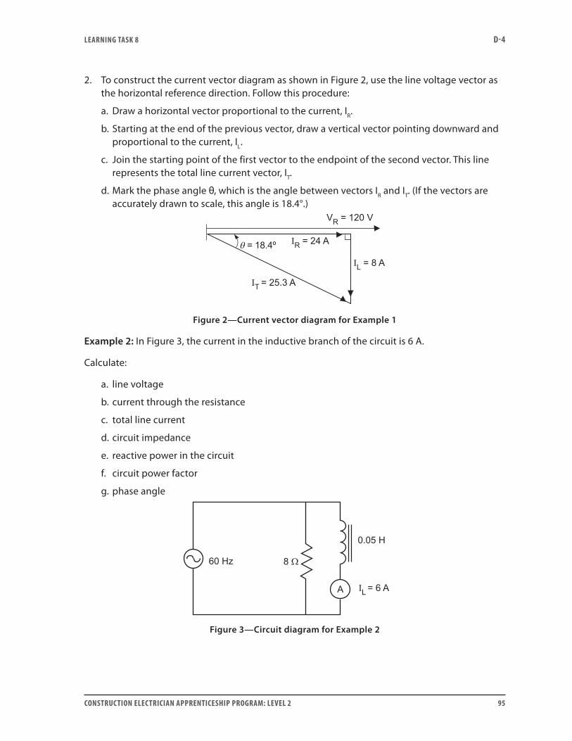
LEARNING TASk 8 D-4
CONSTRUCTION ELECTRICIAN APPRENTICESHIP PROGRAM: LEVEL 2 95
2. To construct the current vector diagram as shown in Figure 2, use the line voltage vector as the horizontal reference direction. Follow this procedure:
a. Draw a horizontal vector proportional to the current, IR.
b. Starting at the end of the previous vector, draw a vertical vector pointing downward and proportional to the current, IL.
c. Join the starting point of the first vector to the endpoint of the second vector. This line represents the total line current vector, IT.
d. Mark the phase angle θ, which is the angle between vectors IR and IT. (If the vectors are accurately drawn to scale, this angle is 18.4°.)
Figure 2—Current vector diagram for Example 1
Example 2: In Figure 3, the current in the inductive branch of the circuit is 6 A.
Calculate:
a. line voltage
b. current through the resistance
c. total line current
d. circuit impedance
e. reactive power in the circuit
f. circuit power factor
g. phase angle
Figure 3—Circuit diagram for Example 2
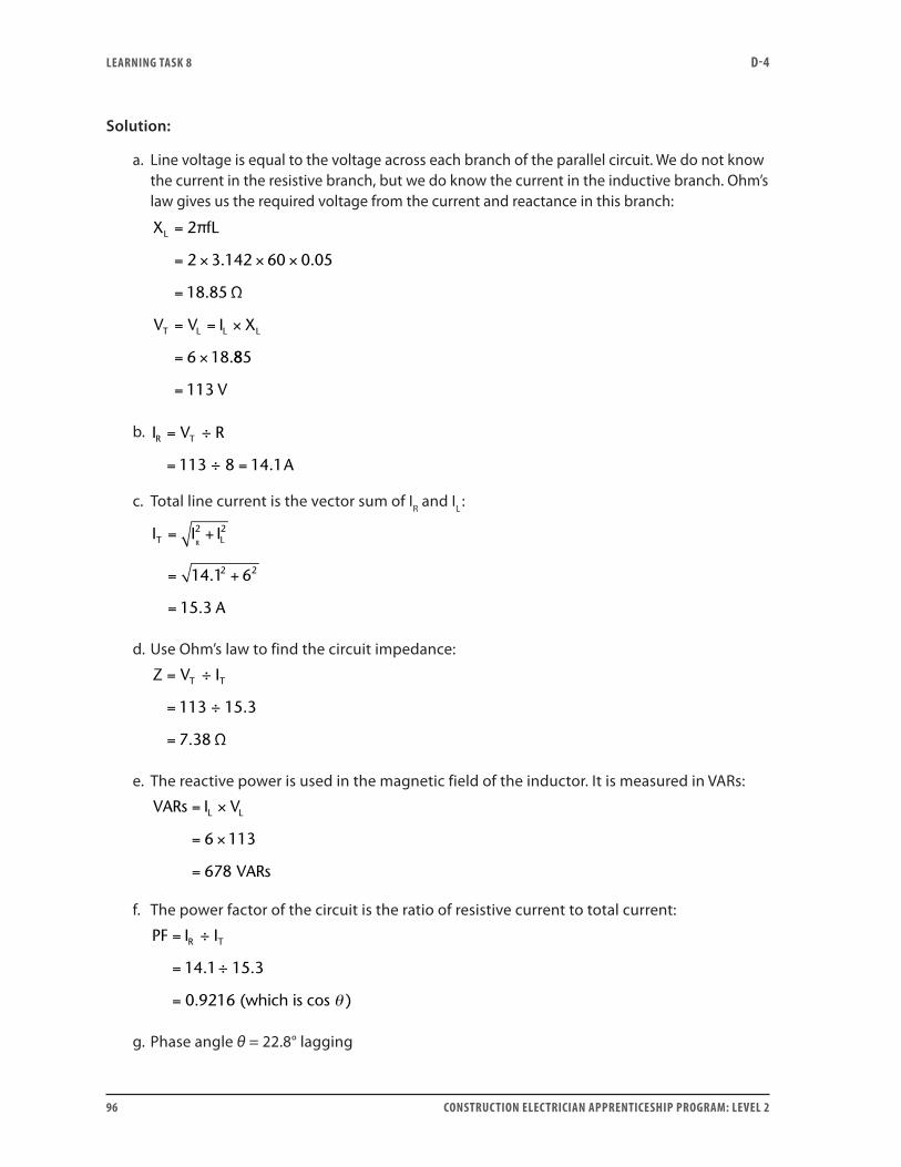
LEARNING TASk 8 D-4
96 CONSTRUCTION ELECTRICIAN APPRENTICESHIP PROGRAM: LEVEL 2
Solution:
a. Line voltage is equal to the voltage across each branch of the parallel circuit. We do not know the current in the resistive branch, but we do know the current in the inductive branch. Ohm’s law gives us the required voltage from the current and reactance in this branch:
X fL
V V I X
L
T L L L
=
= × × ×
=
= = ×
= ×
2
2 3 142 60 0 05
18 85
6 18
π
Ω
. .
.
.885
113= V
b. I V R
A
R T=
= =
÷
÷113 8 14 1.
c. Total line current is the vector sum of IR and IL :
I I I
A
T LR= +
= +
=
2 2
2 214 1 6
15 3
.
.
d. Use Ohm’s law to find the circuit impedance:
Z V IT T=
=
=
÷
÷
Ω
113 15 3
7 38
.
.
e. The reactive power is used in the magnetic field of the inductor. It is measured in VARs:
VARs I VL L= ×
= ×
=
6 113
678 VARs
f. The power factor of the circuit is the ratio of resistive current to total current:
PF I IR T=
=
=
÷
÷
(which is cos )
14 1 15 3
0 9216
. .
. θ
g. Phase angle θ = 22.8° lagging
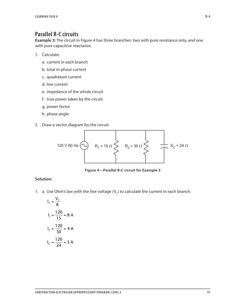
LEARNING TASk 8 D-4
CONSTRUCTION ELECTRICIAN APPRENTICESHIP PROGRAM: LEVEL 2 97
Parallel R-C circuitsExample 3: The circuit in Figure 4 has three branches: two with pure resistance only, and one with pure capacitive reactance.
1. Calculate:
a. current in each branch
b. total in-phase current
c. quadrature current
d. line current
e. impedance of the whole circuit
f. true power taken by the circuit
g. power factor
h. phase angle
2. Draw a vector diagram for the circuit.
Figure 4—Parallel R-C circuit for Example 3
Solution:
1. a. Use Ohm’s law with the line voltage (VT) to calculate the current in each branch:
IVR
I A
I A
I A
TT
C
=
= =
= =
= =
1
2
12015
8
12030
4
12024
5
LEARNING TASk 8 D-4
98 CONSTRUCTION ELECTRICIAN APPRENTICESHIP PROGRAM: LEVEL 2
b. The in-phase current is the combined current (IR) in the two resistive branches. Because they are in phase with each other, you may add them arithmetically.
I I I
A
R = +
= + =
1 2
8 4 12
c. The quadrature current is simply the current in the capacitive branch. This was calculated previously as IC = 5 A. It leads the voltage by 90°.
d. Calculate total line current by adding the in-phase and quadrature currents vectorially:
I I I
A
T R C= +
= +
=
2 2
2 212 5
13
e. Calculate the impedance of the total circuit using Ohm’s law.
ZVI
T
T
=
= =12013
9 23. Ω
Alternatively, use the rule for impedance in parallel circuits:
Z
R XC
= +
=
1
1 1
1
110
2 2
+
= =
2 2124
9 2357 600
676. Ω
f. The true power is measured in watts and taken by the resistive part of the circuit:
P V I
W
T R= ×
= × =120 12 1440
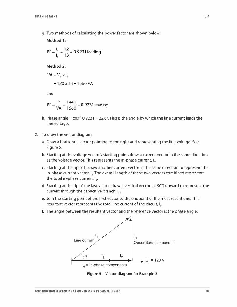
LEARNING TASk 8 D-4
CONSTRUCTION ELECTRICIAN APPRENTICESHIP PROGRAM: LEVEL 2 99
g. Two methods of calculating the power factor are shown below:
Method 1:
PF
IIR
T
= = =1213
0 9231. leading
Method 2:
VA V IT T= ×
= × =120 13 1560 VA
and
PF
PVA
= = =14401560
leading0 9231.
h. Phase angle = cos–1 0.9231 = 22.6°. This is the angle by which the line current leads the line voltage.
2. To draw the vector diagram:
a. Draw a horizontal vector pointing to the right and representing the line voltage. See Figure 5.
b. Starting at the voltage vector’s starting point, draw a current vector in the same direction as the voltage vector. This represents the in-phase current, I1.
c. Starting at the tip of I1, draw another current vector in the same direction to represent the in-phase current vector, I2. The overall length of these two vectors combined represents the total in-phase current, IR.
d. Starting at the tip of the last vector, draw a vertical vector (at 90°) upward to represent the current through the capacitive branch, IC.
e. Join the starting point of the first vector to the endpoint of the most recent one. This resultant vector represents the total line current of the circuit, IT.
f. The angle between the resultant vector and the reference vector is the phase angle.
Figure 5—Vector diagram for Example 3
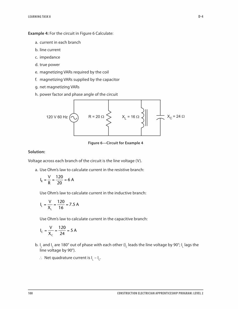
LEARNING TASk 8 D-4
100 CONSTRUCTION ELECTRICIAN APPRENTICESHIP PROGRAM: LEVEL 2
Example 4: For the circuit in Figure 6 Calculate:
a. current in each branch
b. line current
c. impedance
d. true power
e. magnetizing VARs required by the coil
f. magnetizing VARs supplied by the capacitor
g. net magnetizing VARs
h. power factor and phase angle of the circuit
Figure 6—Circuit for Example 4
Solution:
Voltage across each branch of the circuit is the line voltage (V).
a. Use Ohm’s law to calculate current in the resistive branch:
I
VR
AR = = =12020
6
Use Ohm’s law to calculate current in the inductive branch:
I
VX
ALL
= = =12016
7 5.
Use Ohm’s law to calculate current in the capacitive branch:
I
VX
ACC
= = =12024
5
b. IL and IC are 180° out of phase with each other (IC leads the line voltage by 90°; IL lags the line voltage by 90°).
∴ Net quadrature current is IL – IC.
LEARNING TASk 8 D-4
CONSTRUCTION ELECTRICIAN APPRENTICESHIP PROGRAM: LEVEL 2 101
Calculate the line current using the Pythagorean Theorem:
I I I I
A
T R L C= + −
= + − =
2 2
2 26 7 5 5 6 5
( )
( . ) .
c. Use Ohm’s law to calculate impedance:
Z
VIT
= = =1206 5
18 5.
. Ω
d. Use any one of the three power equations to calculate true power:
P
VR
W= = =2 2120
20720
Check this result using P VI I RR R= = 2 .
e. Use any one of the three power equations to calculate magnetizing VARs for the inductor:
VARs I V VARsL L= × = × =7 5 120 900.
Check this result using VARsVX
I XLL
L L= = ×2
2 .
f. Use any one of the three power equations to calculate magnetizing VARs supplied by the capacitor:
VARs I X VARsC C C= × = × =2 25 24 600
Check this result using VARsVX
V ICC
C= = ×2
.
g. Net magnetizing VARs supplied by the line is the difference between the magnetizing energy required by the coil and that supplied by the capacitor:
VARs VARs VARs VARsL C= − = − =900 600 300
h. Calculate the power factor of the circuit using either the current ratio or the power ratio:
PFP
VI
PFII
T
R
T
= =×
=
= = =
720120 6 5
0 923
66 5
0 923
..
..
Because the current through the coil is larger than the current through the capacitor, the phase angle is lagging.
Use PF = cos θ to calculate the phase angle:
θ = cos–1 0.923 = 22.6°, lagging

LEARNING TASk 8 D-4
102 CONSTRUCTION ELECTRICIAN APPRENTICESHIP PROGRAM: LEVEL 2
Parallel circuit resonanceExample 5: The circuit in Figure 7 is in resonance.
Calculate:
a. capacitance (C)
b. inductive and capacitive reactance (XL and XC)
c. currents (IL and IC) in the inductive and capacitive branches
d. line current (IT)
e. circuit impedance (Z)
f. apparent power in the circuit
g. power factor and phase angle
Figure 7—Resonant circuit for Example 5
Solution:
a. At resonance, XL = XC
21
2
14
14 3 142 60 0 042
167
2 2
2 2
≠ fLfC
Cf L
F
=
=
=× × ×
=
π
π
. .
b. Also,
X X fLC L= =
= × × × =
2
2 3 142 60 0 042 15 8 16
π
Ω ≈ Ω. . .
c. Using Ohm’s law,
LEARNING TASk 8 D-4
CONSTRUCTION ELECTRICIAN APPRENTICESHIP PROGRAM: LEVEL 2 103
IVX
A
I I A
LL
C L
=
= =
= =
24016
15
15
d. Line current is the same as current in the resistive branch:
IVR
A
T =
= =24020
12
e. Circuit impedance is entirely resistive, 20 Ω.
f. At resonance, apparent power is the true power of the circuit, measured in watts.
VA V I
W
P I R
W
T T
T
=
= × =
=
= × =
240 12 2880
12 20 2880
2
2
g. Power factor (P ÷ VA) is 100%.
Phase angle (cos–1θ ) is zero.
Example 6: Analyze the circuit in Figure 8 by calculating:
a. current in each branch
b. true power (PR) developed in the resistor
c. true power (PL) developed in the coil branch
d. effective resistance (RL) of the coil
e. reactance (XL) of the coil
f. VARs and microfarad ratings of the capacitor needed in a third parallel branch to put the circuit into resonance
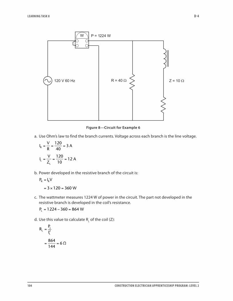
LEARNING TASk 8 D-4
104 CONSTRUCTION ELECTRICIAN APPRENTICESHIP PROGRAM: LEVEL 2
Figure 8—Circuit for Example 6
a. Use Ohm’s law to find the branch currents. Voltage across each branch is the line voltage.
IVR
A
IVZ
A
R
LL
= = =
= = =
12040
3
12010
12
b. Power developed in the resistive branch of the circuit is:
P I V
W
R R=
= × =3 120 360
c. The wattmeter measures 1224 W of power in the circuit. The part not developed in the resistive branch is developed in the coil’s resistance.
P WL = − =1224 360 864
d. Use this value to calculate RL of the coil (Z):
RPIL
L
L
=
= =
2
864144
6 Ω
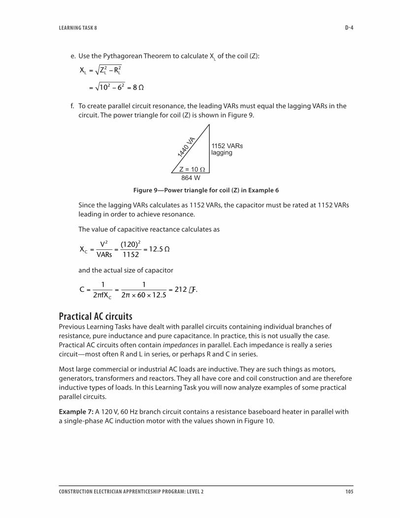
LEARNING TASk 8 D-4
CONSTRUCTION ELECTRICIAN APPRENTICESHIP PROGRAM: LEVEL 2 105
e. Use the Pythagorean Theorem to calculate XL of the coil (Z):
X Z RL L L= −
= − =
2 2
2 210 6 8 Ω
f. To create parallel circuit resonance, the leading VARs must equal the lagging VARs in the circuit. The power triangle for coil (Z) is shown in Figure 9.
Figure 9—Power triangle for coil (Z) in Example 6
Since the lagging VARs calculates as 1152 VARs, the capacitor must be rated at 1152 VARs leading in order to achieve resonance.
The value of capacitive reactance calculates as
X
VVARsC = = =
2 21201152
12 5( )
. Ω
and the actual size of capacitor
C
fXF
C
= =× ×
=1
21
2 60 12 5212
π π ..
Practical AC circuitsPrevious Learning Tasks have dealt with parallel circuits containing individual branches of resistance, pure inductance and pure capacitance. In practice, this is not usually the case. Practical AC circuits often contain impedances in parallel. Each impedance is really a series circuit—most often R and L in series, or perhaps R and C in series.
Most large commercial or industrial AC loads are inductive. They are such things as motors, generators, transformers and reactors. They all have core and coil construction and are therefore inductive types of loads. In this Learning Task you will now analyze examples of some practical parallel circuits.
Example 7: A 120 V, 60 Hz branch circuit contains a resistance baseboard heater in parallel with a single-phase AC induction motor with the values shown in Figure 10.
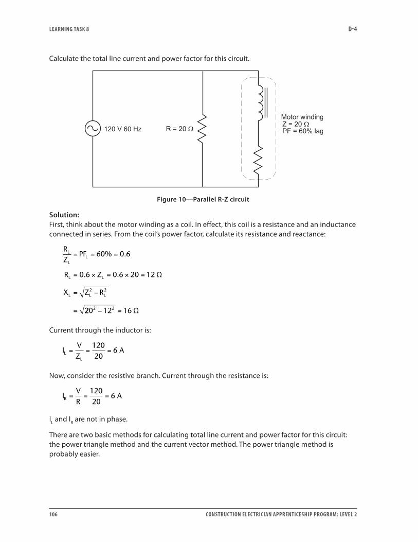
LEARNING TASk 8 D-4
106 CONSTRUCTION ELECTRICIAN APPRENTICESHIP PROGRAM: LEVEL 2
Calculate the total line current and power factor for this circuit.
Figure 10—Parallel R-Z circuit
Solution:First, think about the motor winding as a coil. In effect, this coil is a resistance and an inductance connected in series. From the coil’s power factor, calculate its resistance and reactance:
RZ
PF
R Z
X Z R
L
LL
L L
L L L
= = =
= × = × =
= −
=
60 0 6
0 6 0 6 20 12
2 2
% .
. . Ω
220 12 162 2− = Ω
Current through the inductor is:
IVZ
ALL
= = =12020
6
Now, consider the resistive branch. Current through the resistance is:
IVR
AR = = =12020
6
IL and IR are not in phase.
There are two basic methods for calculating total line current and power factor for this circuit: the power triangle method and the current vector method. The power triangle method is probably easier.
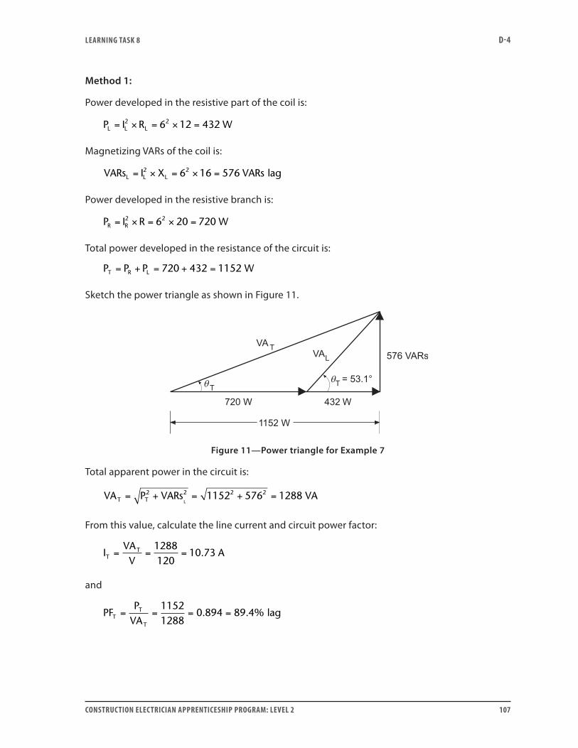
LEARNING TASk 8 D-4
CONSTRUCTION ELECTRICIAN APPRENTICESHIP PROGRAM: LEVEL 2 107
Method 1:
Power developed in the resistive part of the coil is:
P I R WL L L= × = × =2 26 12 432
Magnetizing VARs of the coil is:
VARs I X VARsL L L= × = × =2 26 16 576 lag
Power developed in the resistive branch is:
P I R WR R= × = × =2 26 20 720
Total power developed in the resistance of the circuit is:
P P P WT R L= + = + =720 432 1152
Sketch the power triangle as shown in Figure 11.
Figure 11—Power triangle for Example 7
Total apparent power in the circuit is:
VA P VARs VAT T L= + = + =2 2 2 21152 576 1288
From this value, calculate the line current and circuit power factor:
IVAV
ATT= = =
1288120
10 73.
and
PFP
VATT
T
= = = =11521288
0 894 89 4. . % lag
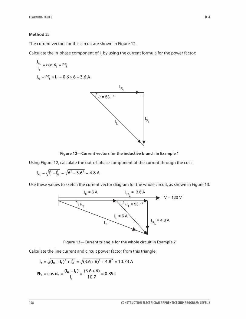
LEARNING TASk 8 D-4
108 CONSTRUCTION ELECTRICIAN APPRENTICESHIP PROGRAM: LEVEL 2
Method 2:
The current vectors for this circuit are shown in Figure 12.
Calculate the in-phase component of IL by using the current formula for the power factor:
IIRL
T
= =
= × = × =
cos PF
I PF I 0.6 6 3.6 A
L L
RL L T
θ
Figure 12—Current vectors for the inductive branch in Example 1
Using Figure 12, calculate the out-of-phase component of the current through the coil:
I I I AXL L RL= − = − =2 2 2 26 3 6 4 8. .
Use these values to sketch the current vector diagram for the whole circuit, as shown in Figure 13.
Figure 13—Current triangle for the whole circuit in Example 7
Calculate the line current and circuit power factor from this triangle:
I I I I A
PF
T RL R XL
T
= + + = + + =
=
( ) ( . ) . .2 2 2 23 6 6 4 8 10 73
cos θTTRL R
T
I II
=+
=+
=( ) ( . )
..
3 6 610 7
0 894
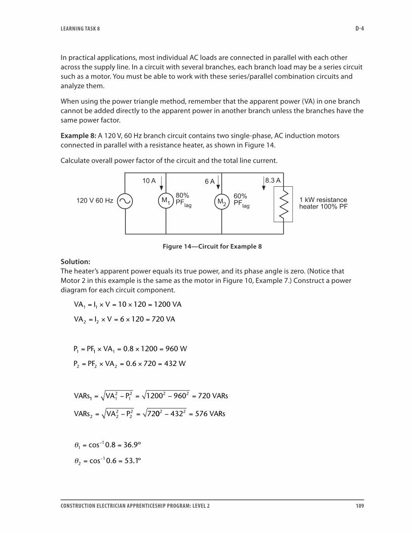
LEARNING TASk 8 D-4
CONSTRUCTION ELECTRICIAN APPRENTICESHIP PROGRAM: LEVEL 2 109
In practical applications, most individual AC loads are connected in parallel with each other across the supply line. In a circuit with several branches, each branch load may be a series circuit such as a motor. You must be able to work with these series/parallel combination circuits and analyze them.
When using the power triangle method, remember that the apparent power (VA) in one branch cannot be added directly to the apparent power in another branch unless the branches have the same power factor.
Example 8: A 120 V, 60 Hz branch circuit contains two single-phase, AC induction motors connected in parallel with a resistance heater, as shown in Figure 14.
Calculate overall power factor of the circuit and the total line current.
Figure 14—Circuit for Example 8
Solution:The heater’s apparent power equals its true power, and its phase angle is zero. (Notice that Motor 2 in this example is the same as the motor in Figure 10, Example 7.) Construct a power diagram for each circuit component.
VA I V VA
VA I V VA
P PF
1 1
2 2
1
10 120 1200
6 120 720
= × = × =
= × = × =
= 11 1
2 2 2
0 8 1200 960
0 6 720 432
× = × =
= × = × =
VA W
P PF VA W
VARs
.
.
11 12
12 2 2
2 22
22
1200 960 720
72
= − = − =
= − =
VA P VARs
VARs VA P 00 432 576
0 8 36 9
0 6 53
2 2
11
21
− =
= =
= =
−
−
VARs
θ
θ
cos . . º
cos . .. º1
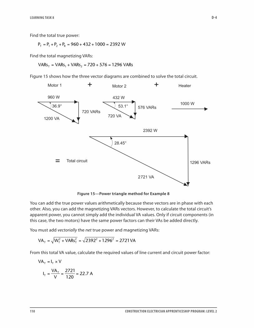
LEARNING TASk 8 D-4
110 CONSTRUCTION ELECTRICIAN APPRENTICESHIP PROGRAM: LEVEL 2
Find the total true power:
P P P P WT R= + + = + + =1 2 960 432 1000 2392
Find the total magnetizing VARs:
VARs VARs VARs VARsT = + = + =1 2 720 576 1296
Figure 15 shows how the three vector diagrams are combined to solve the total circuit.
Figure 15—Power triangle method for Example 8
You can add the true power values arithmetically because these vectors are in phase with each other. Also, you can add the magnetizing VARs vectors. However, to calculate the total circuit’s apparent power, you cannot simply add the individual VA values. Only if circuit components (in this case, the two motors) have the same power factors can their VAs be added directly.
You must add vectorially the net true power and magnetizing VARs:
VA W VARs VAT T T= + = + =2 2 2 22392 1296 2721
From this total VA value, calculate the required values of line current and circuit power factor:
VA I V
IVAV
A
T T
TT
= ×
= = =2721120
22 7.
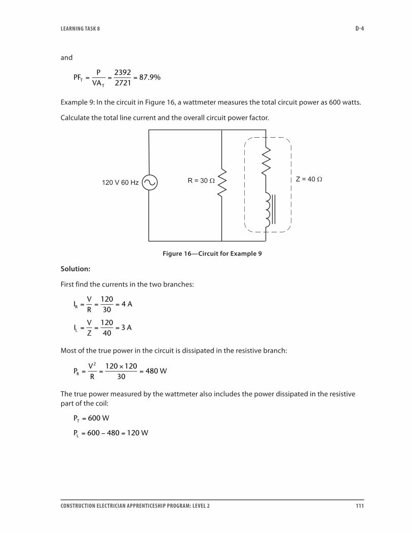
LEARNING TASk 8 D-4
CONSTRUCTION ELECTRICIAN APPRENTICESHIP PROGRAM: LEVEL 2 111
and
PFP
VATT
= = =23922721
87 9. %
Example 9: In the circuit in Figure 16, a wattmeter measures the total circuit power as 600 watts.
Calculate the total line current and the overall circuit power factor.
Figure 16—Circuit for Example 9
Solution:
First find the currents in the two branches:
IVR
A
IVZ
A
R
L
= = =
= = =
12030
4
12040
3
Most of the true power in the circuit is dissipated in the resistive branch:
PVR
WR = =×
=2 120 120
30480
The true power measured by the wattmeter also includes the power dissipated in the resistive part of the coil:
P W
P W
T
L
=
= − =
600
600 480 120
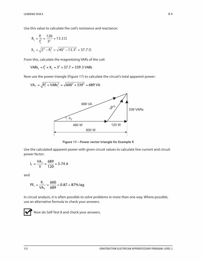
LEARNING TASk 8 D-4
112 CONSTRUCTION ELECTRICIAN APPRENTICESHIP PROGRAM: LEVEL 2
Use this value to calculate the coil’s resistance and reactance:
RPI
X Z R
LL
L
L L
= = =
= − = − =
2
2 2 2 2
12032
13 3
40 13 3 37 7
.
. .
Ω
Ω
From this, calculate the magnetizing VARs of the coil:
VARs I X VARsL L L= × = × =2 23 37 7 339 3. .
Now use the power triangle (Figure 17) to calculate the circuit’s total apparent power:
VA P VARs VAT T L= + = + =2 2 2 2600 339 689
Figure 17—Power vector triangle for Example 9
Use the calculated apparent power with given circuit values to calculate line current and circuit power factor:
IVAV
ATT= = =
689120
5 74.
and
PFP
VATT
T
= = = =600689
0 87 87. % lag
In circuit analysis, it is often possible to solve problems in more than one way. Where possible, use an alternative formula to check your answers.
Now do Self-Test 8 and check your answers.
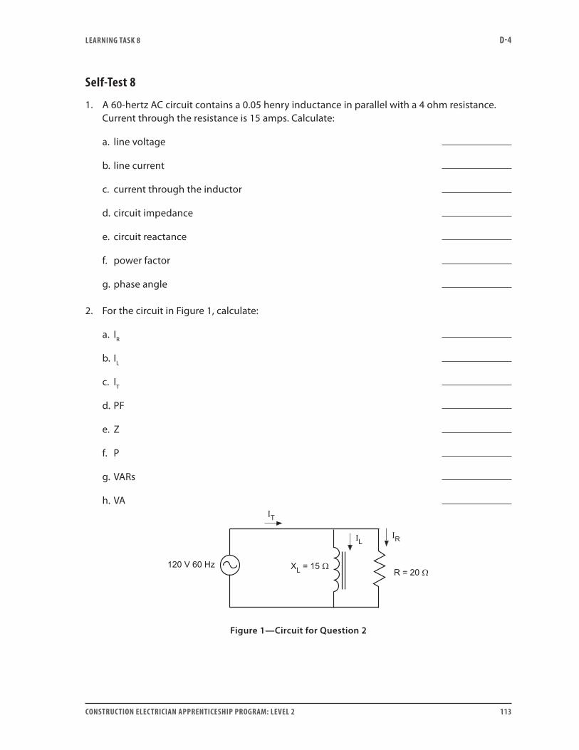
LEARNING TASk 8 D-4
CONSTRUCTION ELECTRICIAN APPRENTICESHIP PROGRAM: LEVEL 2 113
Self-Test 8
1. A 60-hertz AC circuit contains a 0.05 henry inductance in parallel with a 4 ohm resistance. Current through the resistance is 15 amps. Calculate:
a. line voltage
b. line current
c. current through the inductor
d. circuit impedance
e. circuit reactance
f. power factor
g. phase angle
2. For the circuit in Figure 1, calculate:
a. IR
b. IL
c. IT
d. PF
e. Z
f. P
g. VARs
h. VA
Figure 1—Circuit for Question 2
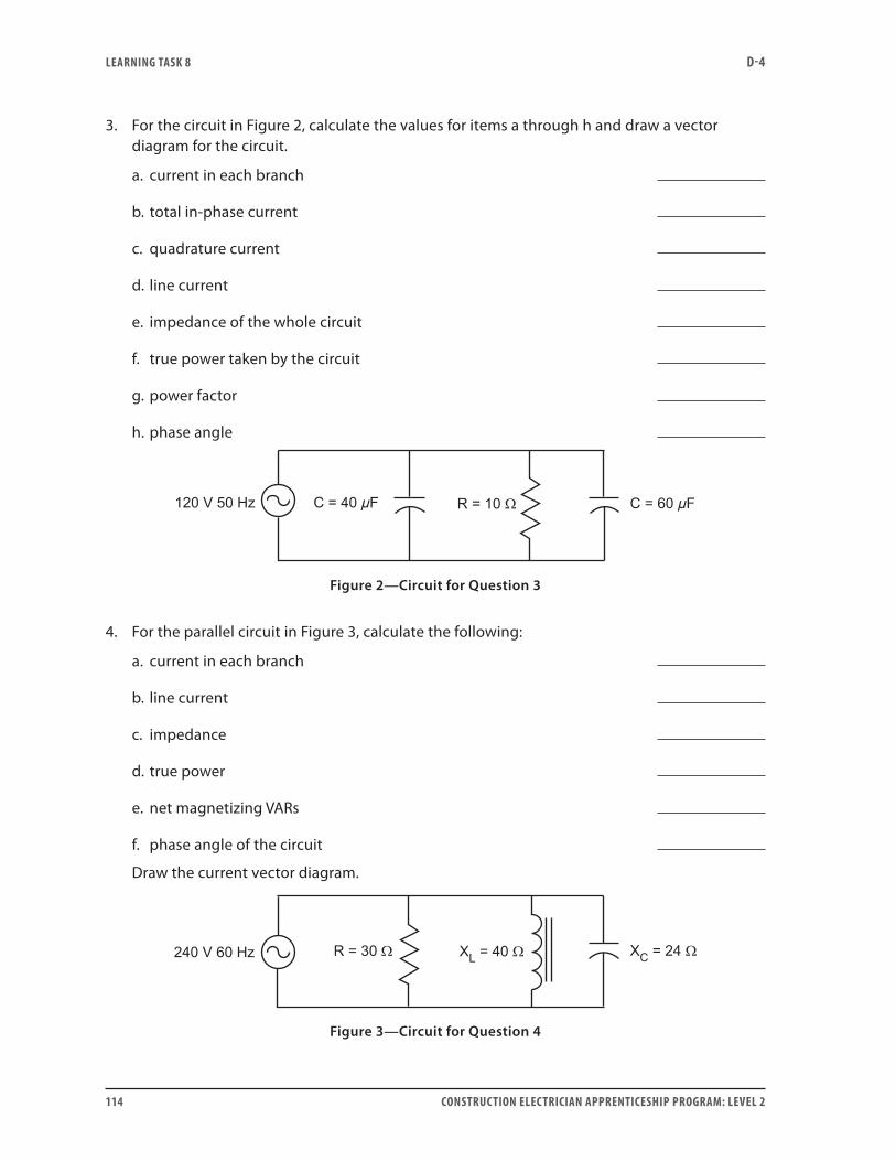
LEARNING TASk 8 D-4
114 CONSTRUCTION ELECTRICIAN APPRENTICESHIP PROGRAM: LEVEL 2
3. For the circuit in Figure 2, calculate the values for items a through h and draw a vector diagram for the circuit.
a. current in each branch
b. total in-phase current
c. quadrature current
d. line current
e. impedance of the whole circuit
f. true power taken by the circuit
g. power factor
h. phase angle
Figure 2—Circuit for Question 3
4. For the parallel circuit in Figure 3, calculate the following:
a. current in each branch
b. line current
c. impedance
d. true power
e. net magnetizing VARs
f. phase angle of the circuit
Draw the current vector diagram.
Figure 3—Circuit for Question 4
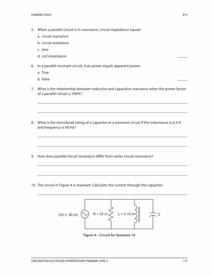
LEARNING TASk 8 D-4
CONSTRUCTION ELECTRICIAN APPRENTICESHIP PROGRAM: LEVEL 2 115
5. When a parallel circuit is in resonance, circuit impedance equals:
a. circuit reactance
b. circuit resistance
c. zero
d. coil impedance
6. In a parallel resonant circuit, true power equals apparent power.
a. True
b. False
7. What is the relationship between inductive and capacitive reactance when the power factor of a parallel circuit is 100%?
8. What is the microfarad rating of a capacitor in a resonant circuit if the inductance is 0.3 H and frequency is 60 Hz?
9. How does parallel circuit resonance differ from series circuit resonance?
10. The circuit in Figure 4 is resonant. Calculate the current through the capacitor.
Figure 4—Circuit for Question 10
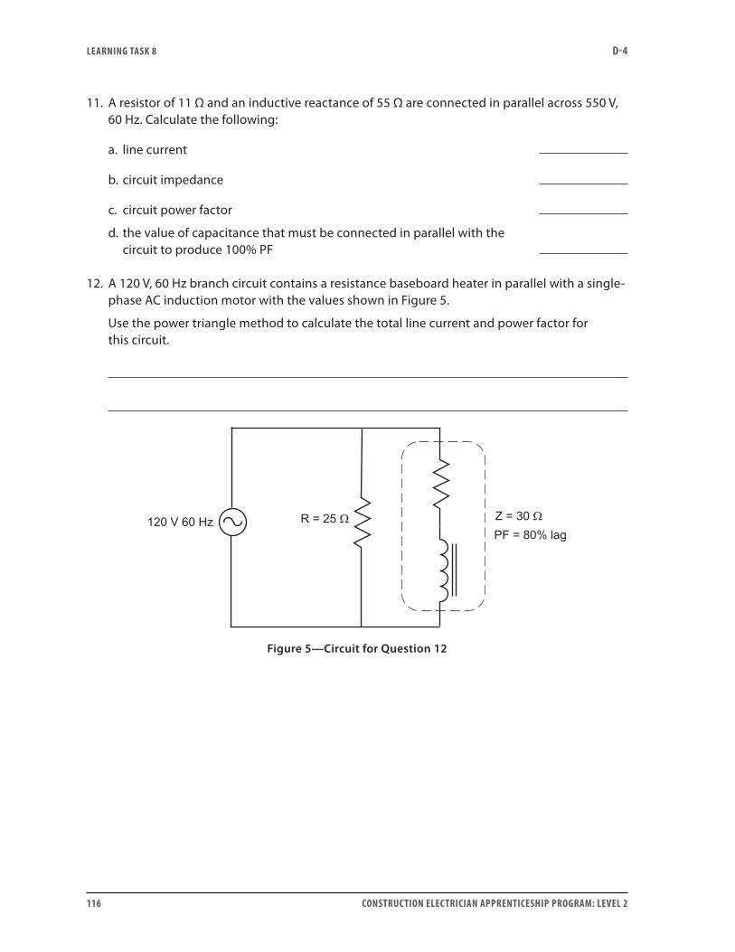
LEARNING TASk 8 D-4
116 CONSTRUCTION ELECTRICIAN APPRENTICESHIP PROGRAM: LEVEL 2
11. A resistor of 11 Ω and an inductive reactance of 55 Ω are connected in parallel across 550 V, 60 Hz. Calculate the following:
a. line current
b. circuit impedance
c. circuit power factor
d. the value of capacitance that must be connected in parallel with the circuit to produce 100% PF
12. A 120 V, 60 Hz branch circuit contains a resistance baseboard heater in parallel with a single-phase AC induction motor with the values shown in Figure 5.
Use the power triangle method to calculate the total line current and power factor for this circuit.
Figure 5—Circuit for Question 12
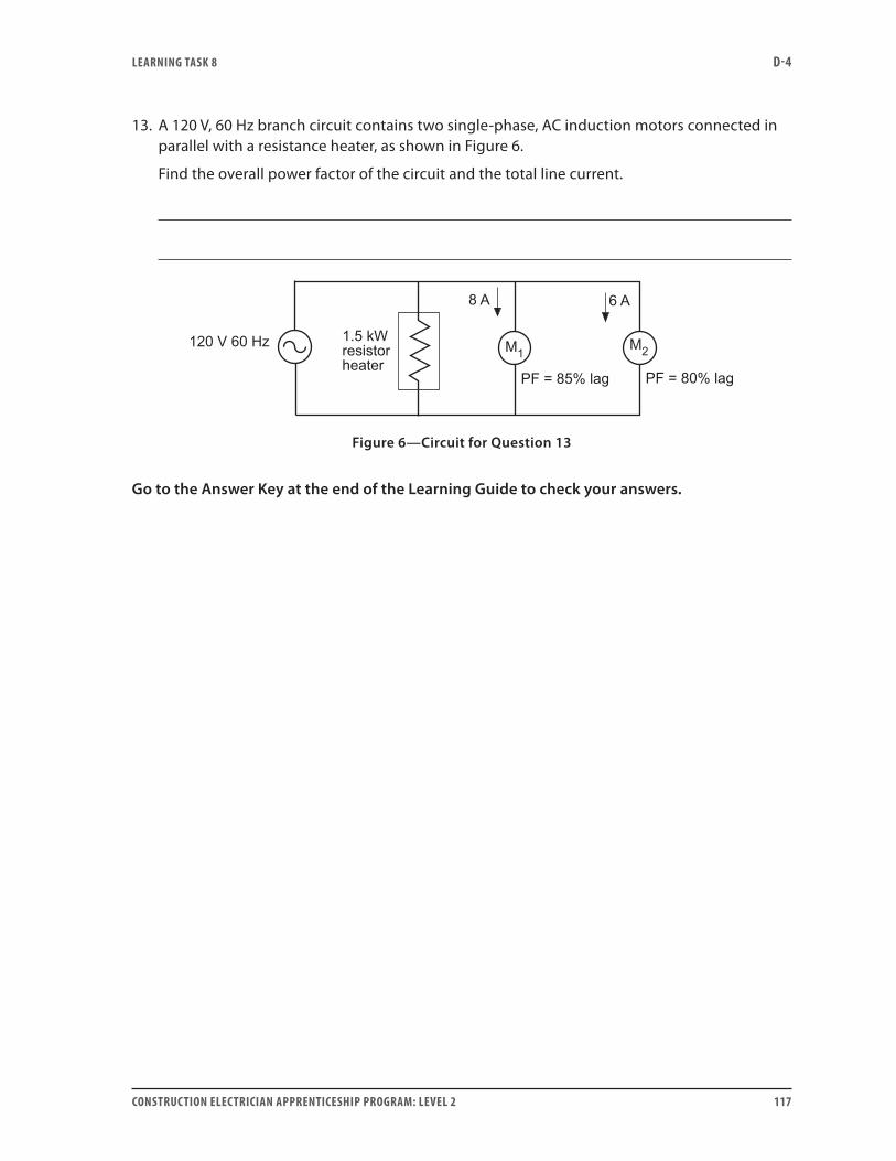
LEARNING TASk 8 D-4
CONSTRUCTION ELECTRICIAN APPRENTICESHIP PROGRAM: LEVEL 2 117
13. A 120 V, 60 Hz branch circuit contains two single-phase, AC induction motors connected in parallel with a resistance heater, as shown in Figure 6.
Find the overall power factor of the circuit and the total line current.
Figure 6—Circuit for Question 13
Go to the Answer Key at the end of the Learning Guide to check your answers.

118 CONSTRUCTION ELECTRICIAN APPRENTICESHIP PROGRAM: LEVEL 2
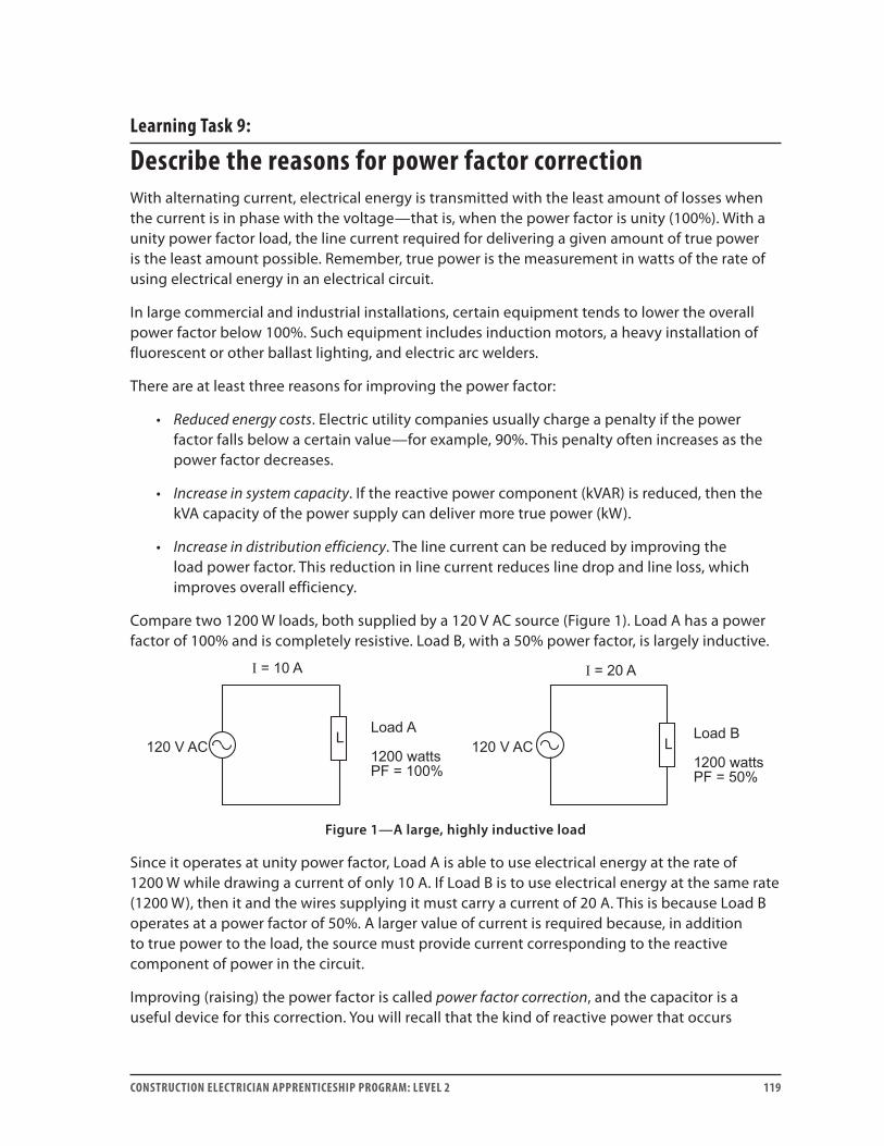
CONSTRUCTION ELECTRICIAN APPRENTICESHIP PROGRAM: LEVEL 2 119
Learning Task 9:
Describe the reasons for power factor correctionWith alternating current, electrical energy is transmitted with the least amount of losses when the current is in phase with the voltage—that is, when the power factor is unity (100%). With a unity power factor load, the line current required for delivering a given amount of true power is the least amount possible. Remember, true power is the measurement in watts of the rate of using electrical energy in an electrical circuit.
In large commercial and industrial installations, certain equipment tends to lower the overall power factor below 100%. Such equipment includes induction motors, a heavy installation of fluorescent or other ballast lighting, and electric arc welders.
There are at least three reasons for improving the power factor:
• Reduced energy costs. Electric utility companies usually charge a penalty if the power factor falls below a certain value—for example, 90%. This penalty often increases as the power factor decreases.
• Increase in system capacity. If the reactive power component (kVAR) is reduced, then the kVA capacity of the power supply can deliver more true power (kW).
• Increase in distribution efficiency. The line current can be reduced by improving the load power factor. This reduction in line current reduces line drop and line loss, which improves overall efficiency.
Compare two 1200 W loads, both supplied by a 120 V AC source (Figure 1). Load A has a power factor of 100% and is completely resistive. Load B, with a 50% power factor, is largely inductive.
Figure 1—A large, highly inductive load
Since it operates at unity power factor, Load A is able to use electrical energy at the rate of 1200 W while drawing a current of only 10 A. If Load B is to use electrical energy at the same rate (1200 W), then it and the wires supplying it must carry a current of 20 A. This is because Load B operates at a power factor of 50%. A larger value of current is required because, in addition to true power to the load, the source must provide current corresponding to the reactive component of power in the circuit.
Improving (raising) the power factor is called power factor correction, and the capacitor is a useful device for this correction. You will recall that the kind of reactive power that occurs

LEARNING TASk 9 D-4
120 CONSTRUCTION ELECTRICIAN APPRENTICESHIP PROGRAM: LEVEL 2
in a capacitance is opposite to that which occurs in an inductance. That is why power factor correction using capacitors works: the two kinds of reactive power cancel each other.
When capacitors are connected to a circuit for power factor correction, it is possible to install too much capacitance. This is called overcorrecting the power factor. The amount of capacitive reactive power drawn might be more than the amount needed to just cancel the inductive reactive power. As a consequence, the wires feeding the circuit may again have to carry extra current.
Because of the danger of overcorrecting—and because of other considerations—it is often unwise to try to correct the power factor to unity. In some circumstances, the power factor of the load itself may change. This can mean that the amount of capacitive adjustment calculated initially may be too much. In such situations, select an intermediate value of power factor: larger than the first one, but less than unity.
Power factor correction, as such, has no effect on the load itself. It acts entirely on the circuit that feeds the load. Therefore, the watts, volts-amps and VARs of the load itself remain unchanged.
Now do Self-Test 9 and check your answers.

LEARNING TASk 9 D-4
CONSTRUCTION ELECTRICIAN APPRENTICESHIP PROGRAM: LEVEL 2 121
Self-Test 9
1. List two types of industrial loads that cause low power factors on electrical systems.
2. For a fixed amount of true power, the AC load that draws the lowest value of current would have a power factor of:
a. 100%
b. 50%
c. 25%
d. 0%
3. List three reasons for correcting the power factor in AC circuits.
4. How is it possible to overcorrect the power factor of a circuit?
5. Why is it not always advisable to try to correct the power factor to unity?
6. When a load is power factor corrected, the watts, VARs and volt-amps of the load device itself:
a. rise
b. fall
c. are unaffected
d. vary cyclically
Go to the Answer Key at the end of the Learning Guide to check your answers.

122 CONSTRUCTION ELECTRICIAN APPRENTICESHIP PROGRAM: LEVEL 2

CONSTRUCTION ELECTRICIAN APPRENTICESHIP PROGRAM: LEVEL 2 123
Learning Task 10:
Describe the application of capacitors for power factor correctionWhen a capacitor is connected to a circuit to correct the power factor, it is connected in parallel with the other loads in the circuit. A capacitor connected in series with an inductive load can achieve a similar effect on the power factor if it is the right size. But we never connect it that way because when a capacitor is connected in series with an inductive load, total opposition to current flow is usually lowered. If the power factor is brought up to unity (100%) by series connection, the opposition to current flow may become dangerously low and nearly result in a short circuit. This is called a series resonant circuit, and, in industrial practice, you must avoid it.
Although a capacitor is always connected in parallel with the existing load to improve power factor, you may still choose where it should be connected. For example, it may be connected in parallel with a main service, with a main feeder or a subfeeder, or with a motor-control centre; or it may simply be connected to the circuit by a switch.
Individual load correctionIf a single, large, inductive load is present, especially one that is sometimes off and sometimes on, it is usually practical to connect one or more capacitors directly in parallel with the load itself. This is often done with large induction motors. The advantage of this is that, when the motor is turned off, the capacitor(s) are also disconnected. That way, there is no danger of a large bank of capacitors overcorrecting the circuit when the motor is switched off. Figure 1 shows this.
Figure 1—Individual load correction
Feeder correctionUsually, it is not practical to connect capacitors in parallel with small induction motors. Therefore, a group of such motors are sometimes power factor corrected by connecting capacitors in parallel with the feeder that supplies the whole set. This is especially effective when all, or most, of the motors operate together, are about the same size and are supplied from a common motor-control centre. The capacitors can then be installed next to the motor-control centre and, by means of switchgear, connected to the busses in it (Figure 2).
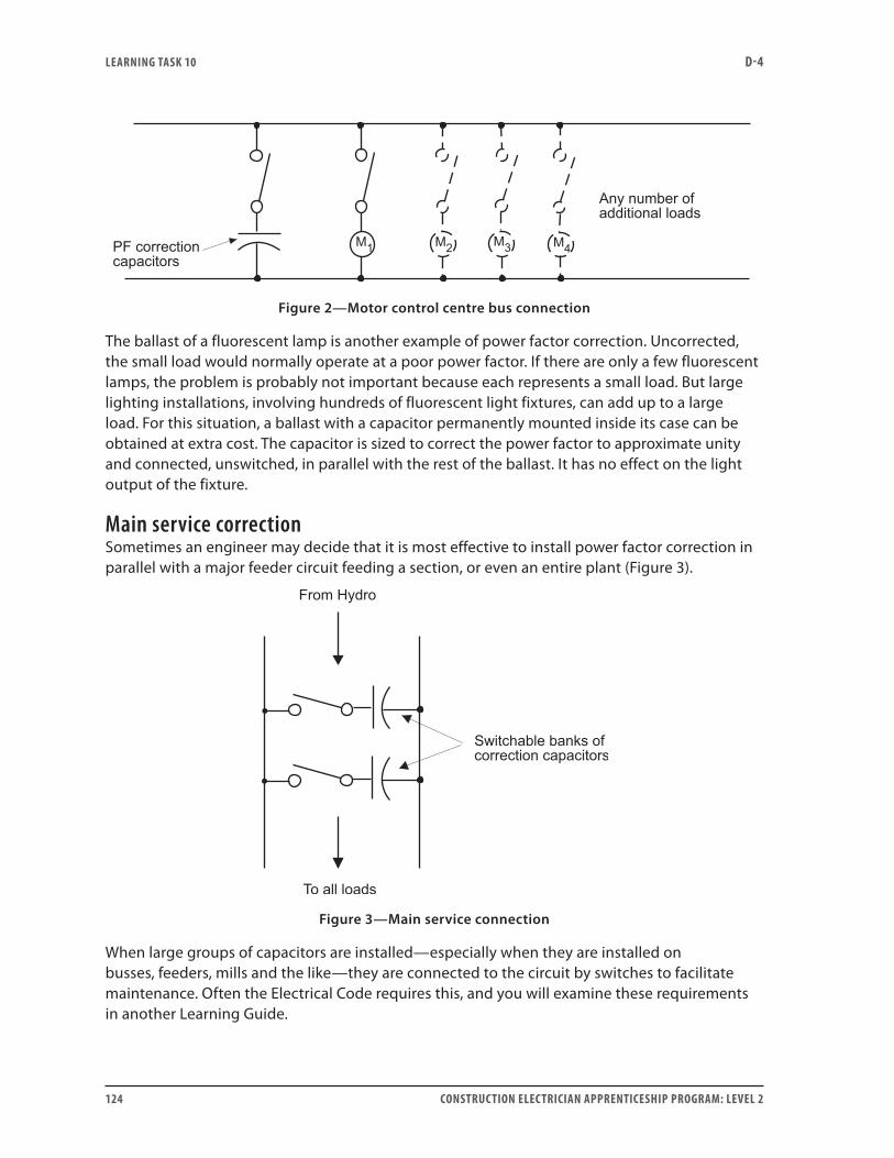
LEARNING TASk 10 D-4
124 CONSTRUCTION ELECTRICIAN APPRENTICESHIP PROGRAM: LEVEL 2
Figure 2—Motor control centre bus connection
The ballast of a fluorescent lamp is another example of power factor correction. Uncorrected, the small load would normally operate at a poor power factor. If there are only a few fluorescent lamps, the problem is probably not important because each represents a small load. But large lighting installations, involving hundreds of fluorescent light fixtures, can add up to a large load. For this situation, a ballast with a capacitor permanently mounted inside its case can be obtained at extra cost. The capacitor is sized to correct the power factor to approximate unity and connected, unswitched, in parallel with the rest of the ballast. It has no effect on the light output of the fixture.
Main service correctionSometimes an engineer may decide that it is most effective to install power factor correction in parallel with a major feeder circuit feeding a section, or even an entire plant (Figure 3).
Figure 3—Main service connection
When large groups of capacitors are installed—especially when they are installed on busses, feeders, mills and the like—they are connected to the circuit by switches to facilitate maintenance. Often the Electrical Code requires this, and you will examine these requirements in another Learning Guide.

LEARNING TASk 10 D-4
CONSTRUCTION ELECTRICIAN APPRENTICESHIP PROGRAM: LEVEL 2 125
Capacitor nameplate dataThe nameplate of an industrial capacitor for power factor correction provides certain information about the capacitor, including:
• Voltage rating
• Frequency rating
• kVARs of correction
• Phase
Voltage ratingFor safety reasons, the voltage rating is important. If the capacitor is used on a system that has a higher voltage than the capacitor is rated for, the capacitor may not be able to withstand the stress. The stress may damage the dielectric (insulation).
This is another example of a general safety practice that you should be familiar with:
Do not connect any piece of equipment to a voltage higher than the rating on the nameplate of the equipment.
Frequency ratingThe frequency rating is the frequency of the voltage system the capacitor is intended for. If the frequency is not the rated value, it will alter the kVARs from the rated value and possibly lead to overheating again.
kVARs of correctionThe data on kVARs of power factor correction is important because the kVARs control the effect the capacitor will have when it is connected to a circuit.
PhaseAlthough you have been working with single-phase constants, many industrial capacitors are intended for use on three-phase systems. Three-phase calculations are dealt with in future studies.
Interaction between voltage, frequency, current and kVARsIt is important that you understand the interaction between voltage, frequency, current and kVARs.
Frequency changesFirst, consider the frequency. You know that capacitive reactance is inversely proportional to frequency. As you learned earlier, reactance changes if frequency is changed. This means that, even with the same applied voltage, the current will change. Then, since capacitive current times the voltage impelling that current equals the capacitive VARs developed, the change in frequency leads to a change in kVARs of correction.
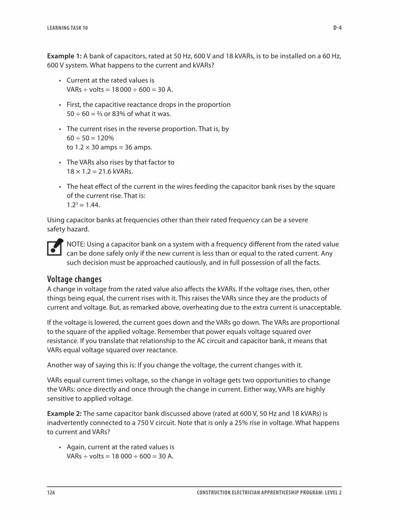
LEARNING TASk 10 D-4
126 CONSTRUCTION ELECTRICIAN APPRENTICESHIP PROGRAM: LEVEL 2
Example 1: A bank of capacitors, rated at 50 Hz, 600 V and 18 kVARs, is to be installed on a 60 Hz, 600 V system. What happens to the current and kVARs?
• Current at the rated values is VARs ÷ volts = 18 000 ÷ 600 = 30 A.
• First, the capacitive reactance drops in the proportion 50 ÷ 60 = 2/3 or 83% of what it was.
• The current rises in the reverse proportion. That is, by 60 ÷ 50 = 120% to 1.2 × 30 amps = 36 amps.
• The VARs also rises by that factor to 18 × 1.2 = 21.6 kVARs.
• The heat effect of the current in the wires feeding the capacitor bank rises by the square of the current rise. That is: 1.22 = 1.44.
Using capacitor banks at frequencies other than their rated frequency can be a severe safety hazard.
NOTE: Using a capacitor bank on a system with a frequency different from the rated value can be done safely only if the new current is less than or equal to the rated current. Any such decision must be approached cautiously, and in full possession of all the facts.
Voltage changesA change in voltage from the rated value also affects the kVARs. If the voltage rises, then, other things being equal, the current rises with it. This raises the VARs since they are the products of current and voltage. But, as remarked above, overheating due to the extra current is unacceptable.
If the voltage is lowered, the current goes down and the VARs go down. The VARs are proportional to the square of the applied voltage. Remember that power equals voltage squared over resistance. If you translate that relationship to the AC circuit and capacitor bank, it means that VARs equal voltage squared over reactance.
Another way of saying this is: If you change the voltage, the current changes with it.
VARs equal current times voltage, so the change in voltage gets two opportunities to change the VARs: once directly and once through the change in current. Either way, VARs are highly sensitive to applied voltage.
Example 2: The same capacitor bank discussed above (rated at 600 V, 50 Hz and 18 kVARs) is inadvertently connected to a 750 V circuit. Note that is only a 25% rise in voltage. What happens to current and VARs?
• Again, current at the rated values is VARs ÷ volts = 18 000 ÷ 600 = 30 A.

LEARNING TASk 10 D-4
CONSTRUCTION ELECTRICIAN APPRENTICESHIP PROGRAM: LEVEL 2 127
• According to Ohm’s law, the current rises in proportion to the voltage. So the new current is 30 × 750 ÷ 600 = 37.5 amps.
• The VARs are now 750 V × 37.5 A = 28.125 kVARs. This is a rise of 56% due to a rise of only 25% in the voltage.
• The current is up by 25%, but its heating effect in the connections, etc., rises by the square of that, or 56%.
• Although the number of watts in a capacitor is normally negligible compared to the VARs, that number is not zero. After all, there are copper wires interconnecting the blocks of capacitance in a bank and they must have a bit of resistance. The heating effects in these will also be proportional to the square of the current flowing.
Now do Self-Test 10 and check your answers.
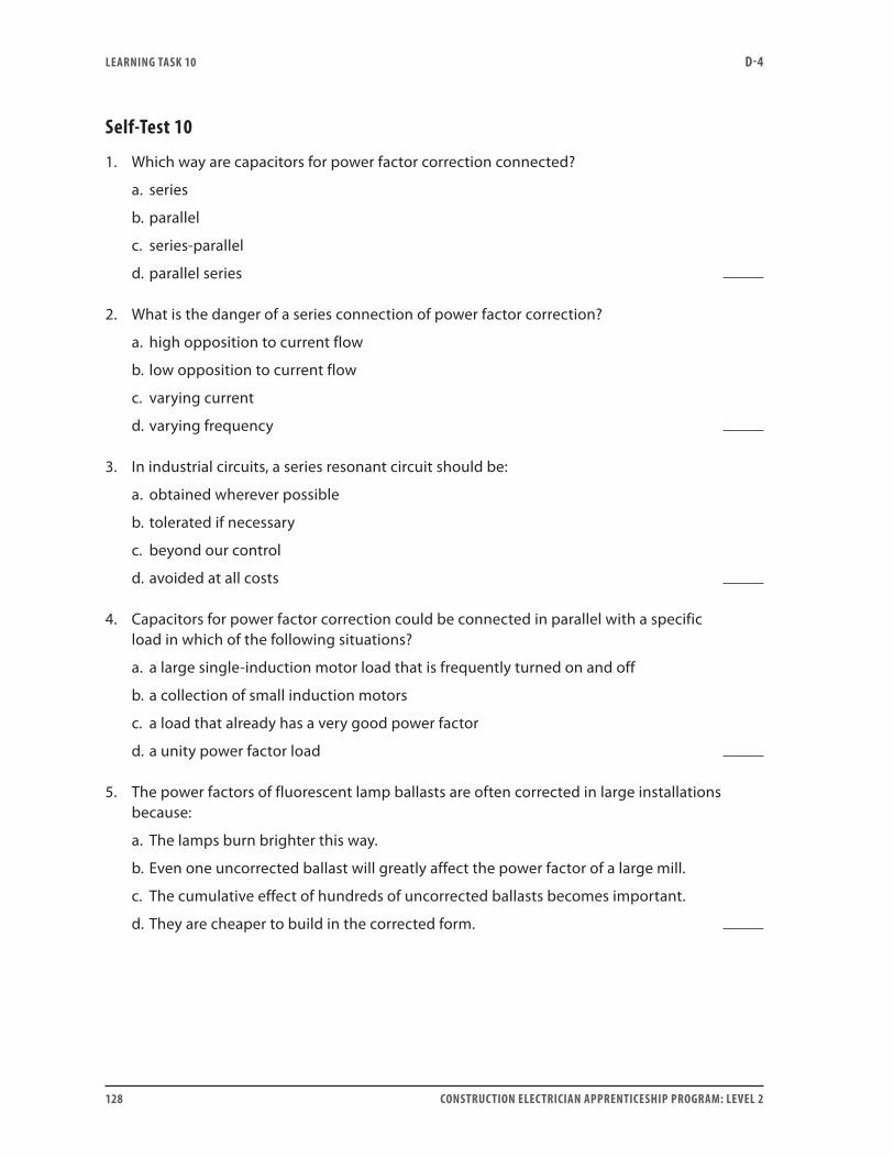
LEARNING TASk 10 D-4
128 CONSTRUCTION ELECTRICIAN APPRENTICESHIP PROGRAM: LEVEL 2
Self-Test 10
1. Which way are capacitors for power factor correction connected?
a. series
b. parallel
c. series-parallel
d. parallel series
2. What is the danger of a series connection of power factor correction?
a. high opposition to current flow
b. low opposition to current flow
c. varying current
d. varying frequency
3. In industrial circuits, a series resonant circuit should be:
a. obtained wherever possible
b. tolerated if necessary
c. beyond our control
d. avoided at all costs
4. Capacitors for power factor correction could be connected in parallel with a specific load in which of the following situations?
a. a large single-induction motor load that is frequently turned on and off
b. a collection of small induction motors
c. a load that already has a very good power factor
d. a unity power factor load
5. The power factors of fluorescent lamp ballasts are often corrected in large installations because:
a. The lamps burn brighter this way.
b. Even one uncorrected ballast will greatly affect the power factor of a large mill.
c. The cumulative effect of hundreds of uncorrected ballasts becomes important.
d. They are cheaper to build in the corrected form.

LEARNING TASk 10 D-4
CONSTRUCTION ELECTRICIAN APPRENTICESHIP PROGRAM: LEVEL 2 129
6. Power factor correction capacitors for fluorescent lamp ballasts are connected:
a. in series with the ballast
b. by using a small switch
c. to every second ballast
d. unswitched
7. In which situation is power factor correction of a group of induction motors practical?
a. where each motor is very large and is sometimes on and sometimes off
b. where all the motors have a good power factor
c. where all the motors are small, about the same size and fed from a common motor-control centre
d. where the motors vary greatly in size and do not operate simultaneously
8. When capacitors for power factor correction are used to correct the power factor of an entire service, or of a main feeder, the capacitors will usually be connected:
a. by flexible cables to facilitate movement
b. by switches that facilitate maintenance
c. in series to lower opposition to current flow
d. in series to increase opposition to current flow
9. List four pieces of information on the nameplate of a power factor correction capacitor.
10. The kVARs developed by a capacitor are most sensitive to:
a. voltage
b. phase
c. frequency
d. impedance

LEARNING TASk 10 D-4
130 CONSTRUCTION ELECTRICIAN APPRENTICESHIP PROGRAM: LEVEL 2
11. If a capacitor bank, rated at 240 V, 60 Hz and 8.4 kVARs, is hooked up to a 240 V, 45 Hz system, the VARs will:
a. rise
b. fall
c. stay the same
12. In the situation described in Question 11, the current will:
a. rise
b. fall
c. stay the same
13. In the situation described in Question 11, the new current is approximately:
a. 15 A
b. 26 A
c. 35 A
d. 40 A
14. In the situation described in Question 11, what will the new VARs be?
a. 3.6 kVARs
b. 6.3 kVARs
c. 8.4 kVARs
d. 16.8 kVARs
15. If a capacitor bank is rated at 600 V, 50 Hz and 9.6 kVARs, and if it is hooked up inadvertently to a 50 Hz, 550 V system, which of the following will happen?
a. The current will go up and the VARs will go down.
b. The VARs will go up and the current will go down.
c. The VARs will go up and the current will go up.
d. The VARs will go down and the current will go down.
16. In the situation described in Question 15, what will the new current be?
a. 14.7 A
b. 15.5 A
c. 16.0 A
d. 17.5 A

LEARNING TASk 10 D-4
CONSTRUCTION ELECTRICIAN APPRENTICESHIP PROGRAM: LEVEL 2 131
17. In the situation described in Question 15, what will the new VARs be?
a. 7.5 kVARs
b. 8.1 kVARs
c. 8.8 kVARs
d. 9.6 kVARs
Go to the Answer Key at the end of the Learning Guide to check your answers.

132 CONSTRUCTION ELECTRICIAN APPRENTICESHIP PROGRAM: LEVEL 2
CONSTRUCTION ELECTRICIAN APPRENTICESHIP PROGRAM: LEVEL 2 133
Learning Task 11:
Solve problems involving power factor correctionBasic calculations for power factor correction start with an uncorrected load whose size and power factor are known. A power triangle is used to represent this uncorrected load. Although it is possible to solve the problem with voltage and current vectors, it is often sufficient—and simpler—to use a power triangle on which real power, apparent power, reactive power, power factor and phase angle are represented.
To construct the triangle (to scale if you don’t have a calculator), use information about the load. You will find that the triangle yields a description of important properties of the load—before and after correction.
In the previous Learning Tasks where you worked with vectors representing voltages and currents in vector diagrams, it was critical that the arrows were oriented correctly. That way you could see the effects of inductance and capacitance in series and parallel circuits. Thus you had rules such as all triangles related to a series inductive circuit point up; all triangles related to a series capacitive circuit point down. In this case, lagging load triangles point up, with watts along the base, and reactive power triangles associated with corrective devices point down. Although not critical, this matches the previous competencies, and is an accepted practice in North America.
Examine the triangles in Figures 1, 2 and 3 on the next pages. Notice that all have a right angle in the bottom right corner. This is always the case, at least for simple problems dealing with power factor correction. The hypotenuse of the triangle represents apparent power (in volt-amps) in the circuit. The horizontal side (the base) represents the real power in watts, and the vertical side represents the reactive power, VARs. The angle in the left corner is the phase angle characteristic of the load. A mathematical property of the phase angle—known as the cosine—represents what we call the power factor.
Keep in mind that it is the power factor/phase angle of the load that determines the shape, or proportions, of the triangle. There is a relationship, however, between the values along the sides of the triangle and the value of the power factor; namely, that the horizontal side divided by the long side equals the power factor (as a decimal). This can be expressed as:
The base of the triangle divided by the hypotenuse equals the power factor (as a decimal).
Expressing that in terms of the quantities involved:
The power factor is always equal to the watts divided by the volt-amps.
In Figure 1, the tall narrow shape indicates a poor power factor (a large phase angle), while the numbers along the sides tell us this is a large load. It is probably a large uncorrected induction motor.
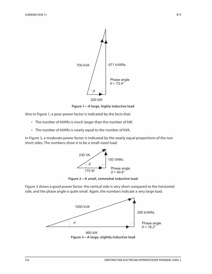
LEARNING TASk 11 D-4
134 CONSTRUCTION ELECTRICIAN APPRENTICESHIP PROGRAM: LEVEL 2
Figure 1—A large, highly inductive load
Also in Figure 1, a poor power factor is indicated by the facts that:
• The number of kVARs is much larger than the number of kW.
• The number of kVARs is nearly equal to the number of kVA.
In Figure 2, a moderate power factor is indicated by the nearly equal proportions of the two short sides. The numbers show it to be a small-sized load.
Figure 2—A small, somewhat inductive load
Figure 3 shows a good power factor: the vertical side is very short compared to the horizontal side, and the phase angle is quite small. Again, the numbers indicate a very large load.
Figure 3—A large, slightly inductive load
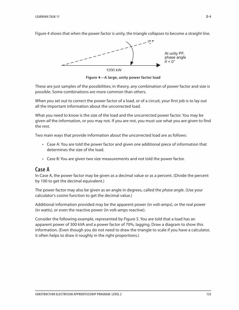
LEARNING TASk 11 D-4
CONSTRUCTION ELECTRICIAN APPRENTICESHIP PROGRAM: LEVEL 2 135
Figure 4 shows that when the power factor is unity, the triangle collapses to become a straight line.
Figure 4—A large, unity power factor load
These are just samples of the possibilities; in theory, any combination of power factor and size is possible. Some combinations are more common than others.
When you set out to correct the power factor of a load, or of a circuit, your first job is to lay out all the important information about the uncorrected load.
What you need to know is the size of the load and the uncorrected power factor. You may be given all the information, or you may not. If you are not, you must use what you are given to find the rest.
Two main ways that provide information about the uncorrected load are as follows:
• Case A: You are told the power factor and given one additional piece of information that determines the size of the load.
• Case B: You are given two size measurements and not told the power factor.
Case AIn Case A, the power factor may be given as a decimal value or as a percent. (Divide the percent by 100 to get the decimal equivalent.)
The power factor may also be given as an angle in degrees, called the phase angle. (Use your calculator’s cosine function to get the decimal value.)
Additional information provided may be the apparent power (in volt-amps), or the real power (in watts), or even the reactive power (in volt-amps reactive).
Consider the following example, represented by Figure 5. You are told that a load has an apparent power of 300 kVA and a power factor of 70%, lagging. Draw a diagram to show this information. (Even though you do not need to draw the triangle to scale if you have a calculator, it often helps to draw it roughly in the right proportions.)
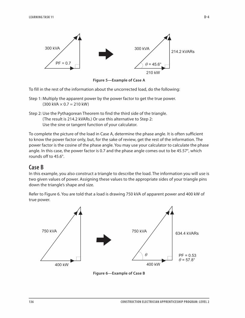
LEARNING TASk 11 D-4
136 CONSTRUCTION ELECTRICIAN APPRENTICESHIP PROGRAM: LEVEL 2
Figure 5—Example of Case A
To fill in the rest of the information about the uncorrected load, do the following:
Step 1: Multiply the apparent power by the power factor to get the true power. (300 kVA × 0.7 = 210 kW)
Step 2: Use the Pythagorean Theorem to find the third side of the triangle. (The result is 214.2 kVARs.) Or use this alternative to Step 2: Use the sine or tangent function of your calculator.
To complete the picture of the load in Case A, determine the phase angle. It is often sufficient to know the power factor only, but, for the sake of review, get the rest of the information. The power factor is the cosine of the phase angle. You may use your calculator to calculate the phase angle. In this case, the power factor is 0.7 and the phase angle comes out to be 45.57°, which rounds off to 45.6°.
Case BIn this example, you also construct a triangle to describe the load. The information you will use is two given values of power. Assigning these values to the appropriate sides of your triangle pins down the triangle’s shape and size.
Refer to Figure 6. You are told that a load is drawing 750 kVA of apparent power and 400 kW of true power.
Figure 6—Example of Case B
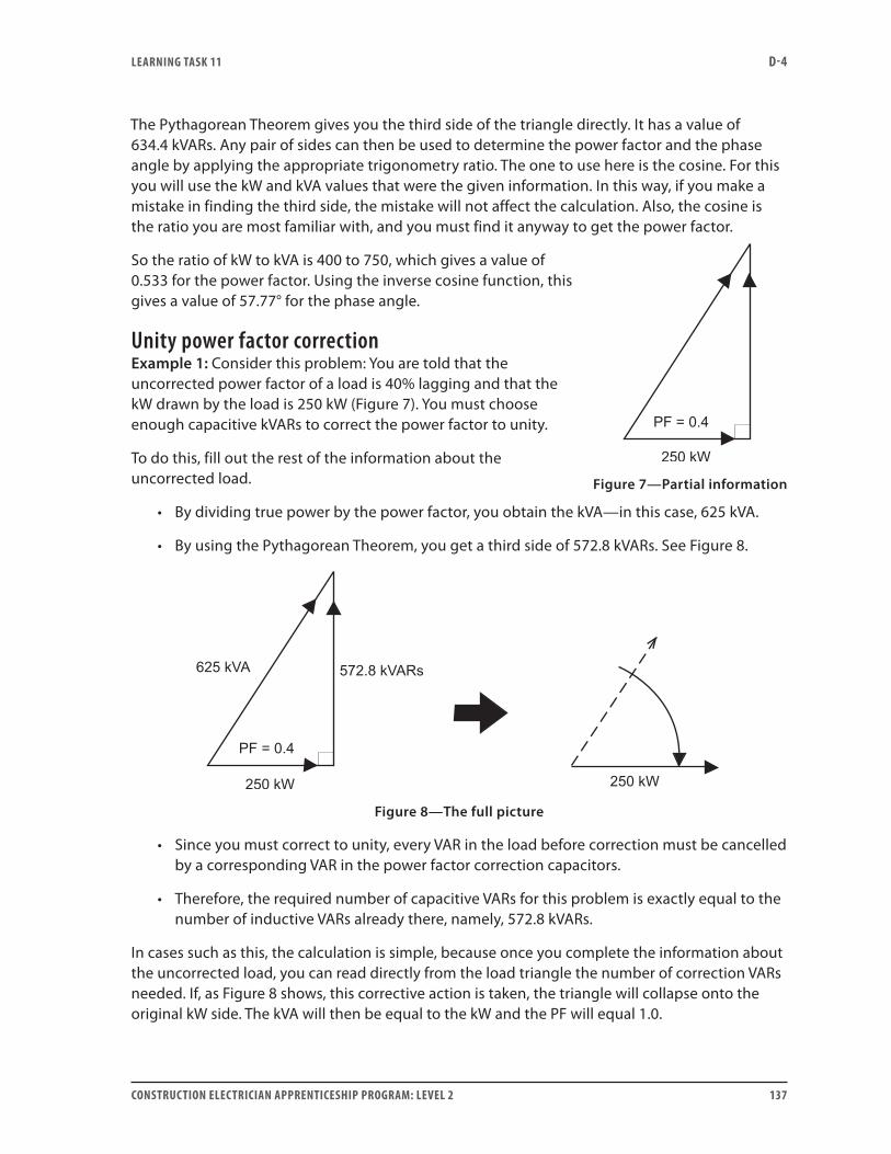
LEARNING TASk 11 D-4
CONSTRUCTION ELECTRICIAN APPRENTICESHIP PROGRAM: LEVEL 2 137
The Pythagorean Theorem gives you the third side of the triangle directly. It has a value of 634.4 kVARs. Any pair of sides can then be used to determine the power factor and the phase angle by applying the appropriate trigonometry ratio. The one to use here is the cosine. For this you will use the kW and kVA values that were the given information. In this way, if you make a mistake in finding the third side, the mistake will not affect the calculation. Also, the cosine is the ratio you are most familiar with, and you must find it anyway to get the power factor.
So the ratio of kW to kVA is 400 to 750, which gives a value of 0.533 for the power factor. Using the inverse cosine function, this gives a value of 57.77° for the phase angle.
Unity power factor correctionExample 1: Consider this problem: You are told that the uncorrected power factor of a load is 40% lagging and that the kW drawn by the load is 250 kW (Figure 7). You must choose enough capacitive kVARs to correct the power factor to unity.
To do this, fill out the rest of the information about the uncorrected load.
• By dividing true power by the power factor, you obtain the kVA—in this case, 625 kVA.
• By using the Pythagorean Theorem, you get a third side of 572.8 kVARs. See Figure 8.
Figure 8—The full picture
• Since you must correct to unity, every VAR in the load before correction must be cancelled by a corresponding VAR in the power factor correction capacitors.
• Therefore, the required number of capacitive VARs for this problem is exactly equal to the number of inductive VARs already there, namely, 572.8 kVARs.
In cases such as this, the calculation is simple, because once you complete the information about the uncorrected load, you can read directly from the load triangle the number of correction VARs needed. If, as Figure 8 shows, this corrective action is taken, the triangle will collapse onto the original kW side. The kVA will then be equal to the kW and the PF will equal 1.0.
Figure 7—Partial information
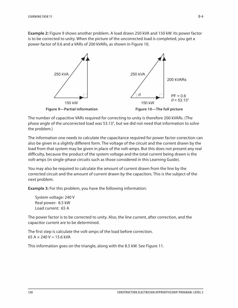
LEARNING TASk 11 D-4
138 CONSTRUCTION ELECTRICIAN APPRENTICESHIP PROGRAM: LEVEL 2
Example 2: Figure 9 shows another problem. A load draws 250 kVA and 150 kW. Its power factor is to be corrected to unity. When the picture of the uncorrected load is completed, you get a power factor of 0.6 and a VARs of 200 kVARs, as shown in Figure 10.
Figure 9—Partial information Figure 10—The full picture
The number of capacitive VARs required for correcting to unity is therefore 200 kVARs. (The phase angle of the uncorrected load was 53.13°, but we did not need that information to solve the problem.)
The information one needs to calculate the capacitance required for power factor correction can also be given in a slightly different form. The voltage of the circuit and the current drawn by the load from that system may be given in place of the volt-amps. But this does not present any real difficulty, because the product of the system voltage and the total current being drawn is the volt-amps (in single-phase circuits such as those considered in this Learning Guide).
You may also be required to calculate the amount of current drawn from the line by the corrected circuit and the amount of current drawn by the capacitors. This is the subject of the next problem.
Example 3: For this problem, you have the following information:
System voltage: 240 V Real power: 8.5 kW Load current: 65 A
The power factor is to be corrected to unity. Also, the line current, after correction, and the capacitor current are to be determined.
The first step is calculate the volt-amps of the load before correction. 65 A × 240 V = 15.6 kVA
This information goes on the triangle, along with the 8.5 kW. See Figure 11.
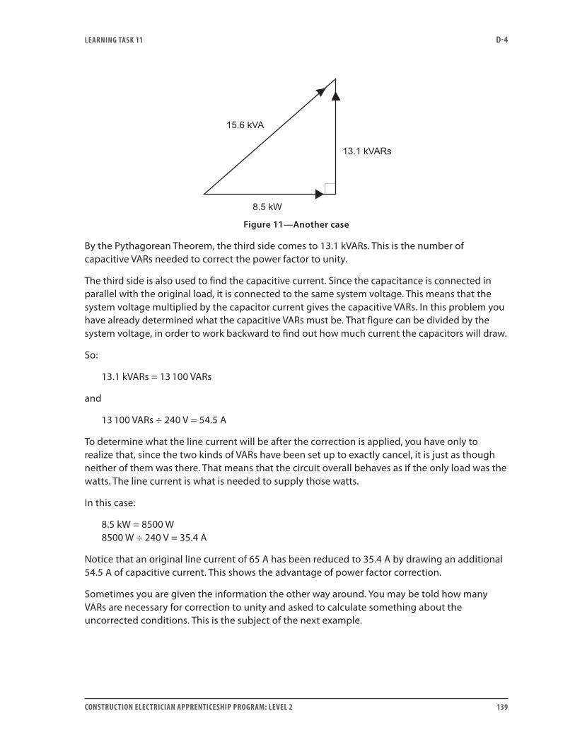
LEARNING TASk 11 D-4
CONSTRUCTION ELECTRICIAN APPRENTICESHIP PROGRAM: LEVEL 2 139
Figure 11—Another case
By the Pythagorean Theorem, the third side comes to 13.1 kVARs. This is the number of capacitive VARs needed to correct the power factor to unity.
The third side is also used to find the capacitive current. Since the capacitance is connected in parallel with the original load, it is connected to the same system voltage. This means that the system voltage multiplied by the capacitor current gives the capacitive VARs. In this problem you have already determined what the capacitive VARs must be. That figure can be divided by the system voltage, in order to work backward to find out how much current the capacitors will draw.
So:
13.1 kVARs = 13 100 VARs
and
13 100 VARs ÷ 240 V = 54.5 A
To determine what the line current will be after the correction is applied, you have only to realize that, since the two kinds of VARs have been set up to exactly cancel, it is just as though neither of them was there. That means that the circuit overall behaves as if the only load was the watts. The line current is what is needed to supply those watts.
In this case:
8.5 kW = 8500 W 8500 W ÷ 240 V = 35.4 A
Notice that an original line current of 65 A has been reduced to 35.4 A by drawing an additional 54.5 A of capacitive current. This shows the advantage of power factor correction.
Sometimes you are given the information the other way around. You may be told how many VARs are necessary for correction to unity and asked to calculate something about the uncorrected conditions. This is the subject of the next example.
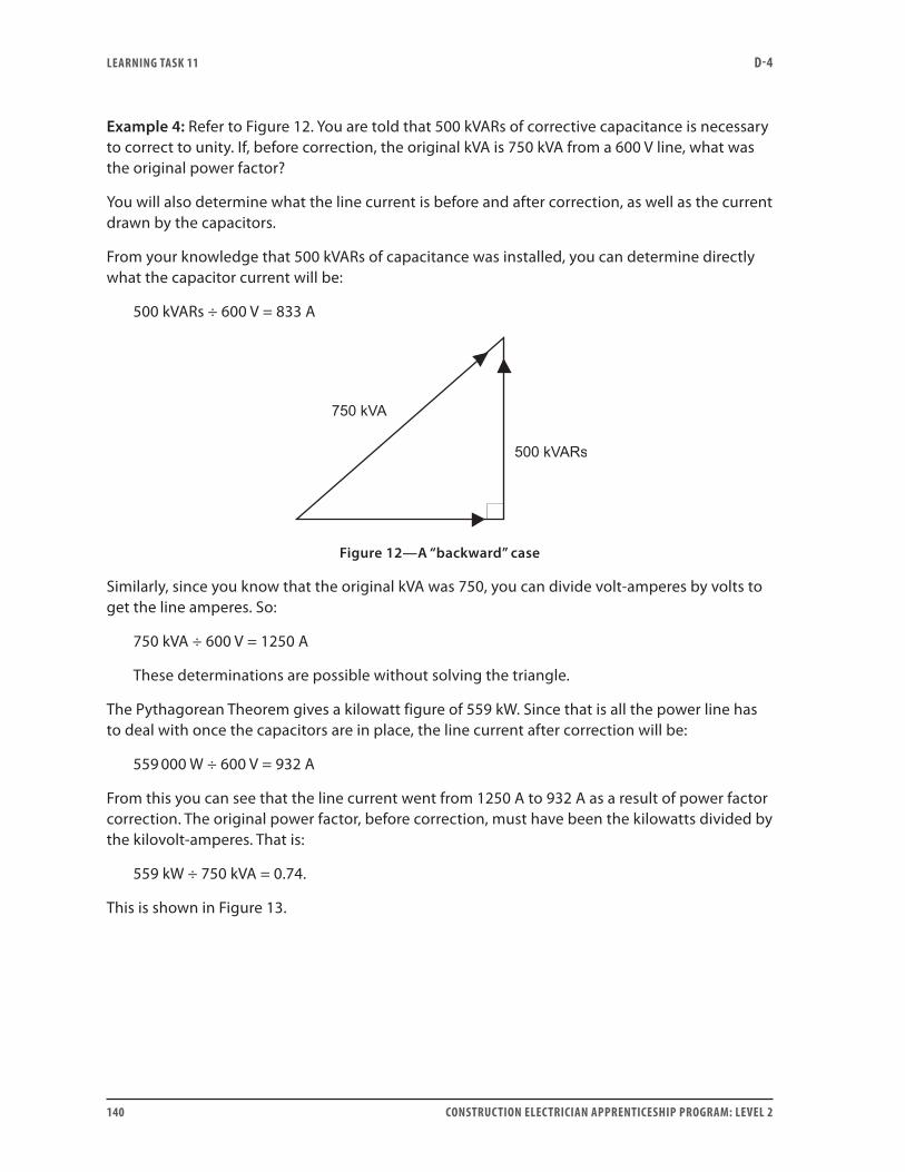
LEARNING TASk 11 D-4
140 CONSTRUCTION ELECTRICIAN APPRENTICESHIP PROGRAM: LEVEL 2
Example 4: Refer to Figure 12. You are told that 500 kVARs of corrective capacitance is necessary to correct to unity. If, before correction, the original kVA is 750 kVA from a 600 V line, what was the original power factor?
You will also determine what the line current is before and after correction, as well as the current drawn by the capacitors.
From your knowledge that 500 kVARs of capacitance was installed, you can determine directly what the capacitor current will be:
500 kVARs ÷ 600 V = 833 A
Figure 12—A “backward” case
Similarly, since you know that the original kVA was 750, you can divide volt-amperes by volts to get the line amperes. So:
750 kVA ÷ 600 V = 1250 A
These determinations are possible without solving the triangle.
The Pythagorean Theorem gives a kilowatt figure of 559 kW. Since that is all the power line has to deal with once the capacitors are in place, the line current after correction will be:
559 000 W ÷ 600 V = 932 A
From this you can see that the line current went from 1250 A to 932 A as a result of power factor correction. The original power factor, before correction, must have been the kilowatts divided by the kilovolt-amperes. That is:
559 kW ÷ 750 kVA = 0.74.
This is shown in Figure 13.
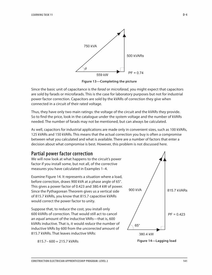
LEARNING TASk 11 D-4
CONSTRUCTION ELECTRICIAN APPRENTICESHIP PROGRAM: LEVEL 2 141
Figure 13—Completing the picture
Since the basic unit of capacitance is the farad or microfarad, you might expect that capacitors are sold by farads or microfarads. This is the case for laboratory purposes but not for industrial power factor correction. Capacitors are sold by the kVARs of correction they give when connected in a circuit of their rated voltage.
Thus, they have only two main ratings: the voltage of the circuit and the kVARs they provide. So to find the price, look in the catalogue under the system voltage and the number of kVARs needed. The number of farads may not be mentioned, but can always be calculated.
As well, capacitors for industrial applications are made only in convenient sizes, such as 100 kVARs, 125 kVARs and 150 kVARs. This means that the actual correction you buy is often a compromise between what you calculated and what is available. There are a number of factors that enter a decision about what compromise is best. However, this problem is not discussed here.
Partial power factor correctionWe will now look at what happens to the circuit’s power factor if you install some, but not all, of the corrective measures you have calculated in Examples 1–4.
Examine Figure 14. It represents a situation where a load, before correction, draws 900 kVA at a phase angle of 65°. This gives a power factor of 0.423 and 380.4 kW of power. Since the Pythagorean Theorem gives us a vertical side of 815.7 kVARs, you know that 815.7 capacitive kVARs would correct the power factor to unity.
Suppose that, to reduce the cost, you install only 600 kVARs of correction. That would still act to cancel an equal amount of the inductive VARs—that is, 600 kVARs inductive. That is, it would reduce the number of inductive VARs by 600 from the uncorrected amount of 815.7 kVARs. That leaves inductive VARs:
815.7– 600 = 215.7 kVARs Figure 14—Lagging load
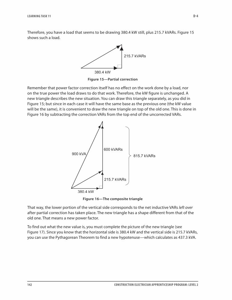
LEARNING TASk 11 D-4
142 CONSTRUCTION ELECTRICIAN APPRENTICESHIP PROGRAM: LEVEL 2
Therefore, you have a load that seems to be drawing 380.4 kW still, plus 215.7 kVARs. Figure 15 shows such a load.
Figure 15—Partial correction
Remember that power factor correction itself has no effect on the work done by a load, nor on the true power the load draws to do that work. Therefore, the kW figure is unchanged. A new triangle describes the new situation. You can draw this triangle separately, as you did in Figure 15; but since in each case it will have the same base as the previous one (the kW value will be the same), it is convenient to draw the new triangle on top of the old one. This is done in Figure 16 by subtracting the correction VARs from the top end of the uncorrected VARs.
Figure 16—The composite triangle
That way, the lower portion of the vertical side corresponds to the net inductive VARs left over after partial correction has taken place. The new triangle has a shape different from that of the old one. That means a new power factor.
To find out what the new value is, you must complete the picture of the new triangle (see Figure 17). Since you know that the horizontal side is 380.4 kW and the vertical side is 215.7 kVARs, you can use the Pythagorean Theorem to find a new hypotenuse—which calculates as 437.3 kVA.
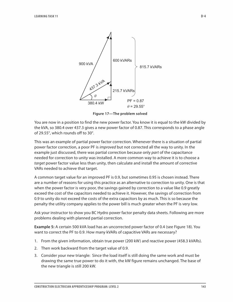
LEARNING TASk 11 D-4
CONSTRUCTION ELECTRICIAN APPRENTICESHIP PROGRAM: LEVEL 2 143
Figure 17—The problem solved
You are now in a position to find the new power factor. You know it is equal to the kW divided by the kVA, so 380.4 over 437.3 gives a new power factor of 0.87. This corresponds to a phase angle of 29.55°, which rounds off to 30°.
This was an example of partial power factor correction. Whenever there is a situation of partial power factor correction, a poor PF is improved but not corrected all the way to unity. In the example just discussed, there was partial correction because only part of the capacitance needed for correction to unity was installed. A more common way to achieve it is to choose a target power factor value less than unity, then calculate and install the amount of corrective VARs needed to achieve that target.
A common target value for an improved PF is 0.9, but sometimes 0.95 is chosen instead. There are a number of reasons for using this practice as an alternative to correction to unity. One is that when the power factor is very poor, the savings gained by correction to a value like 0.9 greatly exceed the cost of the capacitors needed to achieve it. However, the savings of correction from 0.9 to unity do not exceed the costs of the extra capacitors by as much. This is so because the penalty the utility company applies to the power bill is much greater when the PF is very low.
Ask your instructor to show you BC Hydro power factor penalty data sheets. Following are more problems dealing with planned partial correction.
Example 5: A certain 500 kVA load has an uncorrected power factor of 0.4 (see Figure 18). You want to correct the PF to 0.9. How many kVARs of capacitive VARs are necessary?
1. From the given information, obtain true power (200 kW) and reactive power (458.3 kVARs).
2. Then work backward from the target value of 0.9.
3. Consider your new triangle: Since the load itself is still doing the same work and must be drawing the same true power to do it with, the kW figure remains unchanged. The base of the new triangle is still 200 kW.
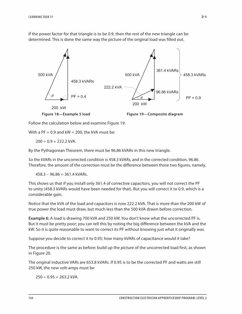
LEARNING TASk 11 D-4
144 CONSTRUCTION ELECTRICIAN APPRENTICESHIP PROGRAM: LEVEL 2
If the power factor for that triangle is to be 0.9, then the rest of the new triangle can be determined. This is done the same way the picture of the original load was filled out.
Figure 18—Example 5 load Figure 19—Composite diagram
Follow the calculation below and examine Figure 19.
With a PF = 0.9 and kW = 200, the kVA must be:
200 ÷ 0.9 = 222.2 kVA.
By the Pythagorean Theorem, there must be 96.86 kVARs in this new triangle.
So the kVARs in the uncorrected condition is 458.3 kVARs, and in the corrected condition, 96.86. Therefore, the amount of the correction must be the difference between those two figures, namely,
458.3 – 96.86 = 361.4 kVARs.
This shows us that if you install only 361.4 of corrective capacitors, you will not correct the PF to unity (458.3 kVARs would have been needed for that). But you will correct it to 0.9, which is a considerable gain.
Notice that the kVA of the load and capacitors is now 222.2 kVA. That is more than the 200 kW of true power the load must draw, but much less than the 500 kVA drawn before correction.
Example 6: A load is drawing 700 kVA and 250 kW. You don’t know what the uncorrected PF is. But it must be pretty poor; you can tell this by noting the big difference between the kVA and the kW. So it is quite reasonable to want to correct its PF without knowing just what it originally was.
Suppose you decide to correct it to 0.95; how many kVARs of capacitance would it take?
The procedure is the same as before: build up the picture of the uncorrected load first, as shown in Figure 20.
The original inductive VARs are 653.8 kVARs. If 0.95 is to be the corrected PF and watts are still 250 kW, the new volt-amps must be
250 ÷ 0.95 = 263.2 kVA.
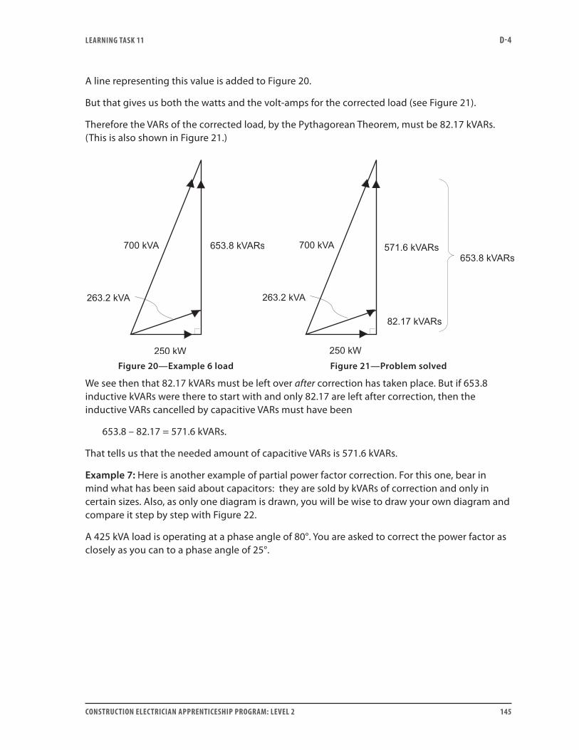
LEARNING TASk 11 D-4
CONSTRUCTION ELECTRICIAN APPRENTICESHIP PROGRAM: LEVEL 2 145
A line representing this value is added to Figure 20.
But that gives us both the watts and the volt-amps for the corrected load (see Figure 21).
Therefore the VARs of the corrected load, by the Pythagorean Theorem, must be 82.17 kVARs. (This is also shown in Figure 21.)
Figure 20—Example 6 load Figure 21—Problem solved
We see then that 82.17 kVARs must be left over after correction has taken place. But if 653.8 inductive kVARs were there to start with and only 82.17 are left after correction, then the inductive VARs cancelled by capacitive VARs must have been
653.8 – 82.17 = 571.6 kVARs.
That tells us that the needed amount of capacitive VARs is 571.6 kVARs.
Example 7: Here is another example of partial power factor correction. For this one, bear in mind what has been said about capacitors: they are sold by kVARs of correction and only in certain sizes. Also, as only one diagram is drawn, you will be wise to draw your own diagram and compare it step by step with Figure 22.
A 425 kVA load is operating at a phase angle of 80°. You are asked to correct the power factor as closely as you can to a phase angle of 25°.
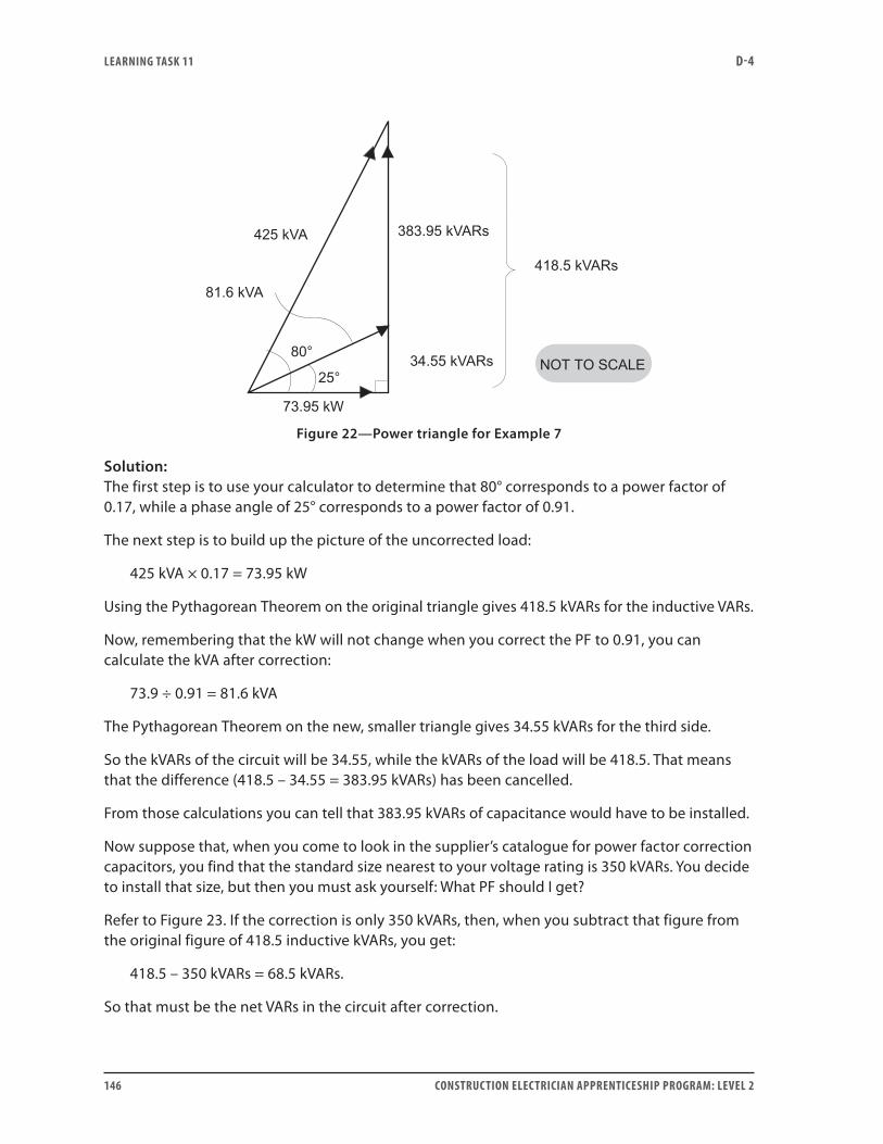
LEARNING TASk 11 D-4
146 CONSTRUCTION ELECTRICIAN APPRENTICESHIP PROGRAM: LEVEL 2
Figure 22—Power triangle for Example 7
Solution:The first step is to use your calculator to determine that 80° corresponds to a power factor of 0.17, while a phase angle of 25° corresponds to a power factor of 0.91.
The next step is to build up the picture of the uncorrected load:
425 kVA × 0.17 = 73.95 kW
Using the Pythagorean Theorem on the original triangle gives 418.5 kVARs for the inductive VARs.
Now, remembering that the kW will not change when you correct the PF to 0.91, you can calculate the kVA after correction:
73.9 ÷ 0.91 = 81.6 kVA
The Pythagorean Theorem on the new, smaller triangle gives 34.55 kVARs for the third side.
So the kVARs of the circuit will be 34.55, while the kVARs of the load will be 418.5. That means that the difference (418.5 – 34.55 = 383.95 kVARs) has been cancelled.
From those calculations you can tell that 383.95 kVARs of capacitance would have to be installed.
Now suppose that, when you come to look in the supplier’s catalogue for power factor correction capacitors, you find that the standard size nearest to your voltage rating is 350 kVARs. You decide to install that size, but then you must ask yourself: What PF should I get?
Refer to Figure 23. If the correction is only 350 kVARs, then, when you subtract that figure from the original figure of 418.5 inductive kVARs, you get:
418.5 – 350 kVARs = 68.5 kVARs.
So that must be the net VARs in the circuit after correction.
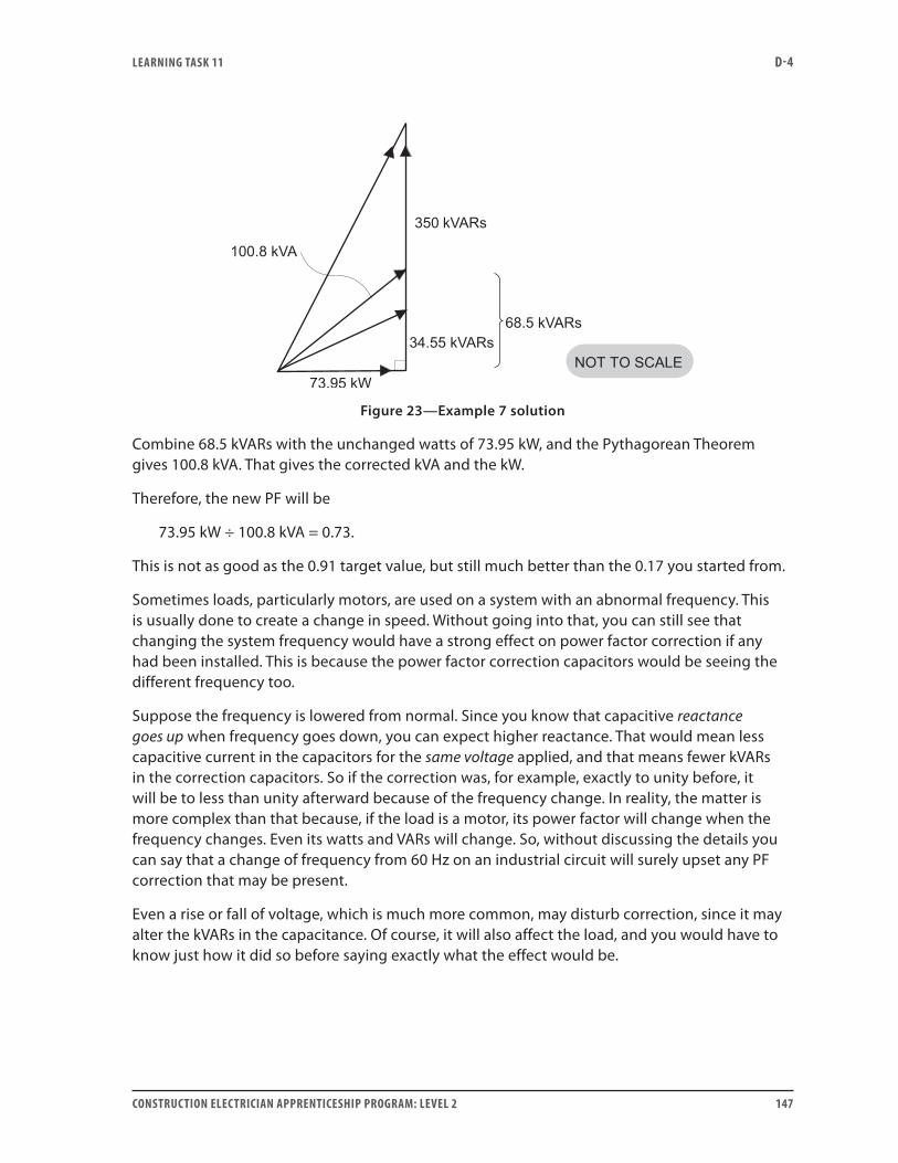
LEARNING TASk 11 D-4
CONSTRUCTION ELECTRICIAN APPRENTICESHIP PROGRAM: LEVEL 2 147
Figure 23—Example 7 solution
Combine 68.5 kVARs with the unchanged watts of 73.95 kW, and the Pythagorean Theorem gives 100.8 kVA. That gives the corrected kVA and the kW.
Therefore, the new PF will be
73.95 kW ÷ 100.8 kVA = 0.73.
This is not as good as the 0.91 target value, but still much better than the 0.17 you started from.
Sometimes loads, particularly motors, are used on a system with an abnormal frequency. This is usually done to create a change in speed. Without going into that, you can still see that changing the system frequency would have a strong effect on power factor correction if any had been installed. This is because the power factor correction capacitors would be seeing the different frequency too.
Suppose the frequency is lowered from normal. Since you know that capacitive reactance goes up when frequency goes down, you can expect higher reactance. That would mean less capacitive current in the capacitors for the same voltage applied, and that means fewer kVARs in the correction capacitors. So if the correction was, for example, exactly to unity before, it will be to less than unity afterward because of the frequency change. In reality, the matter is more complex than that because, if the load is a motor, its power factor will change when the frequency changes. Even its watts and VARs will change. So, without discussing the details you can say that a change of frequency from 60 Hz on an industrial circuit will surely upset any PF correction that may be present.
Even a rise or fall of voltage, which is much more common, may disturb correction, since it may alter the kVARs in the capacitance. Of course, it will also affect the load, and you would have to know just how it did so before saying exactly what the effect would be.
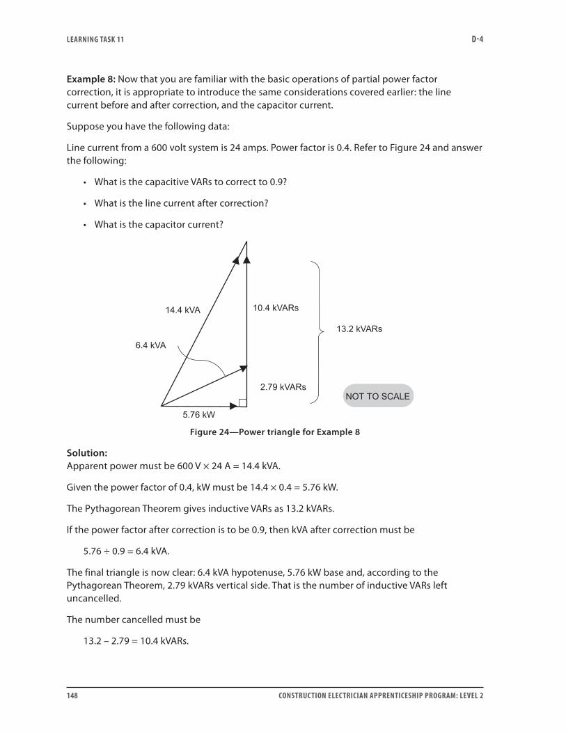
LEARNING TASk 11 D-4
148 CONSTRUCTION ELECTRICIAN APPRENTICESHIP PROGRAM: LEVEL 2
Example 8: Now that you are familiar with the basic operations of partial power factor correction, it is appropriate to introduce the same considerations covered earlier: the line current before and after correction, and the capacitor current.
Suppose you have the following data:
Line current from a 600 volt system is 24 amps. Power factor is 0.4. Refer to Figure 24 and answer the following:
• What is the capacitive VARs to correct to 0.9?
• What is the line current after correction?
• What is the capacitor current?
Figure 24—Power triangle for Example 8
Solution:Apparent power must be 600 V × 24 A = 14.4 kVA.
Given the power factor of 0.4, kW must be 14.4 × 0.4 = 5.76 kW.
The Pythagorean Theorem gives inductive VARs as 13.2 kVARs.
If the power factor after correction is to be 0.9, then kVA after correction must be
5.76 ÷ 0.9 = 6.4 kVA.
The final triangle is now clear: 6.4 kVA hypotenuse, 5.76 kW base and, according to the Pythagorean Theorem, 2.79 kVARs vertical side. That is the number of inductive VARs left uncancelled.
The number cancelled must be
13.2 – 2.79 = 10.4 kVARs.
LEARNING TASk 11 D-4
CONSTRUCTION ELECTRICIAN APPRENTICESHIP PROGRAM: LEVEL 2 149
This is also the number of capacitive kVARs that must be installed to achieve the required cancellation.
With respect to line current and capacitor current:
Line current before correction is given as 24 A.
Apparent power after correction is 6.4 kVA.
6.4 kVA ÷ 600 V = 10.7 A
So 10.7 A is the line current after correction.
This is a big change from 24 A—and that’s correcting only to 0.9.
The current in the capacitors is capacitive VARs divided by system voltage.
In this case:
10.4 kVARs ÷ 600 V = 17.35 A
Note that the current through the load itself is still 24 A. It is only in the common feeder conductors, where both the 24 A and the 17.35 A are flowing, that cancellation can take place. If you tried to measure the current in that common conductor, all you would be able to measure would be the new 10.7 A.
Note that one of the main reasons for power factor correction is to reduce line current to a minimum value.
Now do Self-Test 11 and check your answers.

LEARNING TASk 11 D-4
150 CONSTRUCTION ELECTRICIAN APPRENTICESHIP PROGRAM: LEVEL 2
Self-Test 11
1. The basic diagram representing loads that may need power factor correction is a:
a. voltage vector diagram
b. power triangle
c. power circle
d. current vector diagram
2. The power factor is equal to:
a. kVA divided by kW
b. kVAR divided by kVA
c. kW divided by kVAR
d. kW divided by kVA
3. If a load draws 250 kVA at a power factor of 50%, how many kW does it draw?
a. 500 kW
b. 250 kW
c. 125 kW
d. 62.5 kW
4. If a load draws 800 kW, at a power factor of 40%, how many kVA must it draw?
a. 8000 kVA
b. 2000 kVA
c. 320 kVA
d. 160 kVA
5. If the power factor is 0.95, what is the phase angle?
a. 18°
b. 44°
c. 72°
d. 95°

LEARNING TASk 11 D-4
CONSTRUCTION ELECTRICIAN APPRENTICESHIP PROGRAM: LEVEL 2 151
6. If a load draws 4000 W and 5500 VA, what is the power factor?
a. 68%
b. 73%
c. 94%
d. 138%
7. Refer to your answer to Question 6. How many VARs would the load draw?
a. 6800 VARs
b. 4000 VARs
c. 3775 VARs
d. 1500 VARs
8. If a load draws 200 VARs and 300 W, how many VA must it draw?
a. 500 VA
b. 361 VA
c. 224 VA
d. 100 VA
9. If a load is drawing 380 kW at a PF of 0.7, how many kVARs of capacitance must be added to correct the PF to unity?
a. 266 kVARs
b. 271 kVARs
c. 300 kVARs
d. 388 kVARs
10. If a load is drawing 400 kW and 800 kVA, how many kVARs of capacitance are needed to correct it to unity?
a. 800 kVARs
b. 693 kVARs
c. 511 kVARs
d. 400 kVARs
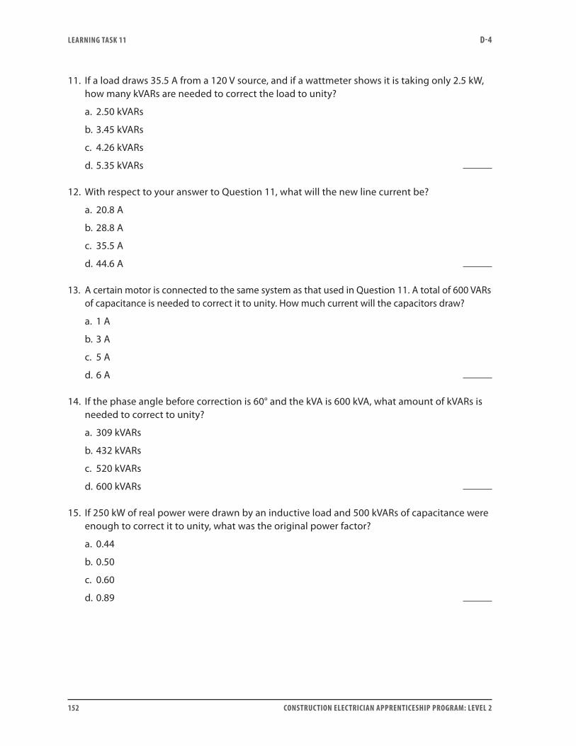
LEARNING TASk 11 D-4
152 CONSTRUCTION ELECTRICIAN APPRENTICESHIP PROGRAM: LEVEL 2
11. If a load draws 35.5 A from a 120 V source, and if a wattmeter shows it is taking only 2.5 kW, how many kVARs are needed to correct the load to unity?
a. 2.50 kVARs
b. 3.45 kVARs
c. 4.26 kVARs
d. 5.35 kVARs
12. With respect to your answer to Question 11, what will the new line current be?
a. 20.8 A
b. 28.8 A
c. 35.5 A
d. 44.6 A
13. A certain motor is connected to the same system as that used in Question 11. A total of 600 VARs of capacitance is needed to correct it to unity. How much current will the capacitors draw?
a. 1 A
b. 3 A
c. 5 A
d. 6 A
14. If the phase angle before correction is 60° and the kVA is 600 kVA, what amount of kVARs is needed to correct to unity?
a. 309 kVARs
b. 432 kVARs
c. 520 kVARs
d. 600 kVARs
15. If 250 kW of real power were drawn by an inductive load and 500 kVARs of capacitance were enough to correct it to unity, what was the original power factor?
a. 0.44
b. 0.50
c. 0.60
d. 0.89

LEARNING TASk 11 D-4
CONSTRUCTION ELECTRICIAN APPRENTICESHIP PROGRAM: LEVEL 2 153
16. Which of the following is a true statement?
a. When the power factor of a load is corrected, the load itself draws fewer watts than it did before.
b. When the power factor of a load is corrected, the load itself draws fewer inductive VARs than it did before.
c. When the power factor of a load is corrected, the load itself draws the same number of watts, volt-amps and VARs as it did before.
d. When the power factor of a load is corrected, the load itself draws fewer volt-amps than it did before.
17. Which of the following is a true statement?
a. When choosing capacitors for industrial power factor correction, it does not matter whether the actual value installed is higher or lower than the calculated value.
b. Manufacturers rate capacitors for industrial power factor correction by the microfarad as well as by the system voltage.
c. Almost any value of kVARs of correction that you may have calculated can be purchased for installation.
d. You may not be able to purchase a capacitor for industrial power factor correction of the size you calculated, so a compromise may be necessary.
18. A certain load is drawing 135 A from a 240 V line, and it is operating at a power factor of 0.5. It is to be corrected to unity with capacitors. How many kVA does it draw before correction?
a. 27.0 kVA
b. 32.4 kVA
c. 67.5 kVA
d. 120.0 kVA
19. How many kW does the load in Question 18 draw before correction?
a. 16.2 kW
b. 33.8 kW
c. 60.0 kW
d. 67.5 kW
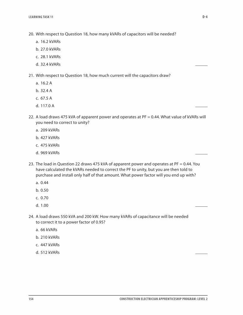
LEARNING TASk 11 D-4
154 CONSTRUCTION ELECTRICIAN APPRENTICESHIP PROGRAM: LEVEL 2
20. With respect to Question 18, how many kVARs of capacitors will be needed?
a. 16.2 kVARs
b. 27.0 kVARs
c. 28.1 kVARs
d. 32.4 kVARs
21. With respect to Question 18, how much current will the capacitors draw?
a. 16.2 A
b. 32.4 A
c. 67.5 A
d. 117.0 A
22. A load draws 475 kVA of apparent power and operates at PF = 0.44. What value of kVARs will you need to correct to unity?
a. 209 kVARs
b. 427 kVARs
c. 475 kVARs
d. 969 kVARs
23. The load in Question 22 draws 475 kVA of apparent power and operates at PF = 0.44. You have calculated the kVARs needed to correct the PF to unity, but you are then told to purchase and install only half of that amount. What power factor will you end up with?
a. 0.44
b. 0.50
c. 0.70
d. 1.00
24. A load draws 550 kVA and 200 kW. How many kVARs of capacitance will be needed to correct it to a power factor of 0.95?
a. 66 kVARs
b. 210 kVARs
c. 447 kVARs
d. 512 kVARs

LEARNING TASk 11 D-4
CONSTRUCTION ELECTRICIAN APPRENTICESHIP PROGRAM: LEVEL 2 155
25. A load draws 600 kW at a PF of 0.45. It is to be corrected to a PF of 0.8. How many kVARs of capacitance will be needed?
a. 600 kVARs
b. 740 kVARs
c. 1190 kVARs
d. 1330 kVARs
26. A load is currently drawing 300 kVARs and 300 kW. How many kVARs of capacitance will be needed to bring the power factor to 0.8?
a. 75 kVARs
b. 225 kVARs
c. 300 kVARs
d. 375 kVARs
27. A load draws 700 kVA at a phase angle of 75°. You must correct the power factor to a phase angle for the circuit of 30°. How many kVARs of capacitance will be necessary?
a. 181 kVARs
b. 210 kVARs
c. 572 kVARs
d. 676 kVARs
28. If, in the case of Question 27, it is necessary to downsize the capacitor to the next even hundred of kVARs, what PF will you get?
a. 0.26
b. 0.34
c. 0.72
d. 0.87
29. A rise in the voltage applied to a power factor correction capacitor would cause which of the following?
a. a rise in the kVARs in the capacitor
b. a change in the frequency of the circuit
c. a fall in the kVARs in the capacitor
d. no change in the kVARs in the capacitor

LEARNING TASk 11 D-4
156 CONSTRUCTION ELECTRICIAN APPRENTICESHIP PROGRAM: LEVEL 2
30. A lowering of the frequency applied to a power factor correction capacitor would cause the kVARs in the capacitor to:
a. not change
b. rise
c. fall
d. impossible to say
31. You are given the following data:
Line current before correction: 36 A System voltage: 500 V Power factor before correction: 0.6 Target power factor: 0.95
How many VARs of capacitance are needed?
a. 3.6 kVARs
b. 10.9 kVARs
c. 14.4 kVARs
d. 18.0 kVARs
32. Given the data in Question 31, what is the new line current?
a. 18.0 A
b. 21.6 A
c. 22.7 A
d. 28.8 A
33. Given the data in Question 31, how much current will the power factor correction capacitors draw?
a. 7.2 A
b. 18.0 A
c. 21.8 A
d. 28.8 A
Go to the Answer Key at the end of the Learning Guide to check your answers.

ANSwER kEY D-4
CONSTRUCTION ELECTRICIAN APPRENTICESHIP PROGRAM: LEVEL 2 157
Answer keySelf-Test 11. 0°
2. b. ohms (Ω)
3. lags
4. a. positive
5. The inductive and resistive voltages are vector quantities, out of phase with each other. They must be added as vectors, taking direction (phase angle) into account.
6. Impedance is the combined opposition to current flow in a circuit.
7. Z R XL
= + = +( )or Z R X2L2
8. in the resistance of the circuit
9. reactive power (quadrature, wattless); associated with the inductive reactance
10. VA W VARs= +2 2
11. The power factor represents the proportion of the apparent power of a circuit that is usable in the load of the circuit and not used in the reactance of the circuit.
12. The angle θ is the phase angle of the circuit. It is the angle between the line current and supply voltage of an AC circuit. It occurs in the voltage, power and impedance triangles. For example, in the voltage triangle, θ is the angle between VR and VT.
Self-Test 21. a. ohms
2. leads
3. c. zero
4. b. False
5. Z X R X RC C= + = +2 2 or Z
6. b. developed almost entirely in the resistance of the circuit
7. VARs VA W= −2 2
8. cos θ = PF
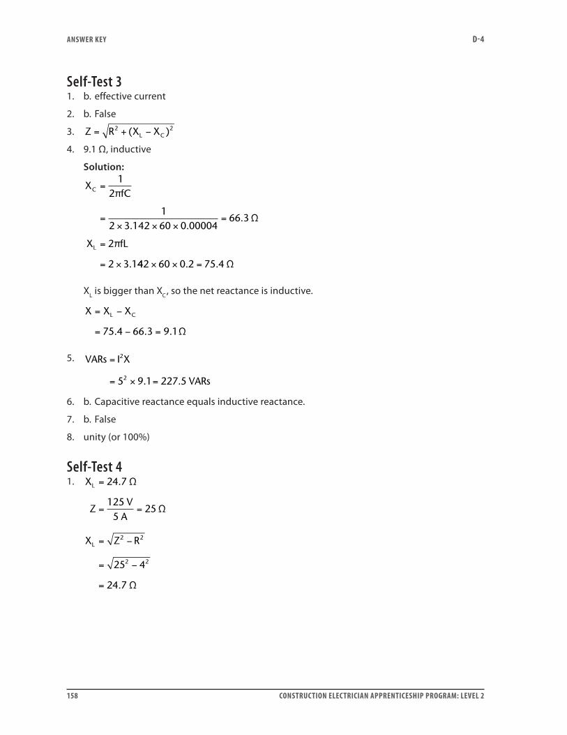
ANSwER kEY D-4
158 CONSTRUCTION ELECTRICIAN APPRENTICESHIP PROGRAM: LEVEL 2
Self-Test 31. b. effective current
2. b. False
3. Z R X XL C= + −2 2( )
4. 9.1 Ω, inductive
Solution:
XfC
X fL
C
L
=
=× × ×
=
=
= ×
12
12 3 142 60 0 00004
66 3
2
2 3 1
π
Ω
π
. ..
. 442 60 0 2 75 4× × =. . Ω
XL is bigger than XC, so the net reactance is inductive.
X X XL C= −
= − =75 4 66 3 9 1. . . Ω
5. VARs I X
VARs
=
= × =
2
25 9 1 227 5. .
6. b. Capacitive reactance equals inductive reactance.
7. b. False
8. unity (or 100%)
Self-Test 41. X
ZV
A
X Z R
L
L
=
= =
= −
= −
=
24 7
1255
25
25 4
24 7
2 2
2 2
.
.
Ω
Ω
Ω
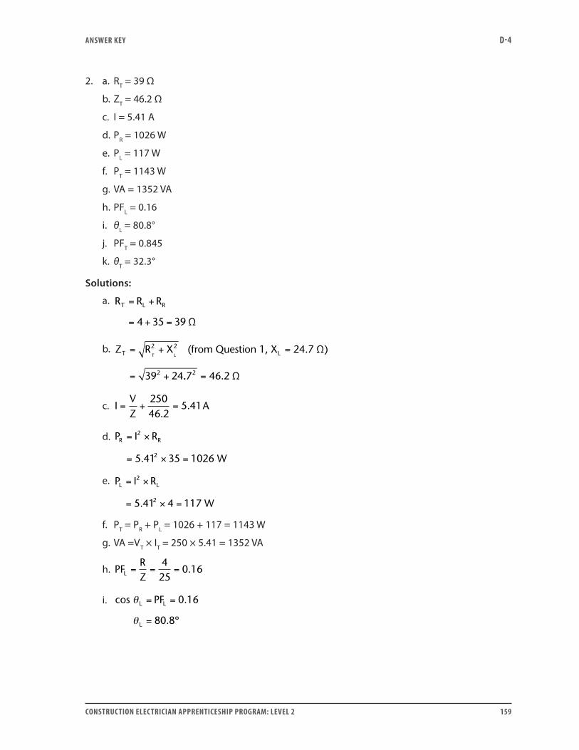
ANSwER kEY D-4
CONSTRUCTION ELECTRICIAN APPRENTICESHIP PROGRAM: LEVEL 2 159
2. a. RT = 39 Ω
b. ZT = 46.2 Ω
c. I = 5.41 A
d. PR = 1026 W
e. PL = 117 W
f. PT = 1143 W
g. VA = 1352 VA
h. PFL = 0.16
i. θL = 80.8°
j. PFT = 0.845
k. θT = 32.3°
Solutions:
a. R R RT L R= +
= + =4 35 39 Ω
b. Z R XT T L= + =
= +
2 2
239 24
(from Question 1, X 24.7 ΩL )
.. .7 46 22 = Ω
c. IVZ
A= + =25046 2
5 41.
.
d. P I R
W
R R= ×
= × =
2
25 41 35 1026.
e. P I R
W
L L= ×
= × =
2
25 41 4 117.
f. PT = PR + PL = 1026 + 117 = 1143 W
g. VA =VT × IT = 250 × 5.41 = 1352 VA
h. PFRZL = = =
425
0 16.
i. cos PF 0.16L L
L
θ
θ
= =
= 80 8. º
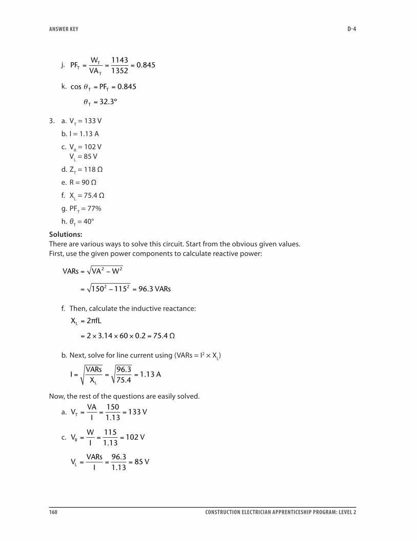
ANSwER kEY D-4
160 CONSTRUCTION ELECTRICIAN APPRENTICESHIP PROGRAM: LEVEL 2
j. PFWVAT
T
T
= = =11431352
0 845.
k. cos PF 0.845T T
T
θ
θ
= =
= 32 3. º
3. a. VT = 133 V
b. I = 1.13 A
c. VR = 102 V VL = 85 V
d. ZT = 118 Ω
e. R = 90 Ω
f. XL = 75.4 Ω
g. PFT = 77%
h. θT = 40°
Solutions:There are various ways to solve this circuit. Start from the obvious given values. First, use the given power components to calculate reactive power:
VARs VA W
VARs
= −
= − =
2 2
2 2150 115 96 3.
f. Then, calculate the inductive reactance:
X fLL =
= × × × =
2
2 3 14 60 0 2 75 4
π
Ω. . .
b. Next, solve for line current using (VARs = I2 × XL)
IVARsX
AL
= = =96 375 4
1 13..
.
Now, the rest of the questions are easily solved.
a. VVAI
VT = = =1501 13
133.
c. VWI
VR = = =1151 13
102.
V
VARsI
VL = = =96 31 13
85.
.
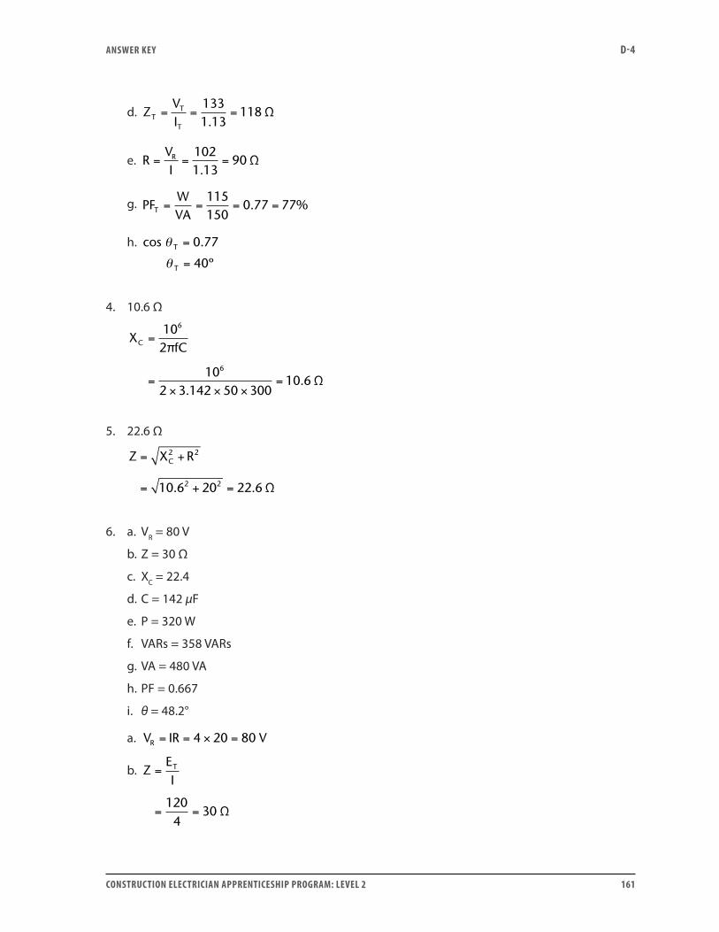
ANSwER kEY D-4
CONSTRUCTION ELECTRICIAN APPRENTICESHIP PROGRAM: LEVEL 2 161
d. ZVIT
T
T
= = =1331 13
118.
Ω
e. RVIR= = =
1021 13
90.
Ω
g. PFWVAT = = = =
115150
0 77 77. %
h. cos θ T = 0 77.
θ T = 40º
4. 10.6 Ω
XfCC =
=× × ×
=
102
102 3 142 50 300
10 6
6
6
π
Ω.
.
5. 22.6 Ω
Z X RC= +
= + =
2 2
2 210 6 20 22 6. . Ω
6. a. VR = 80 V
b. Z = 30 Ω
c. XC = 22.4
d. C = 142 µF
e. P = 320 W
f. VARs = 358 VARs
g. VA = 480 VA
h. PF = 0.667
i. θ = 48.2°
a. V IR VR = = × =4 20 80
b. ZEIT=
= =120
430 Ω
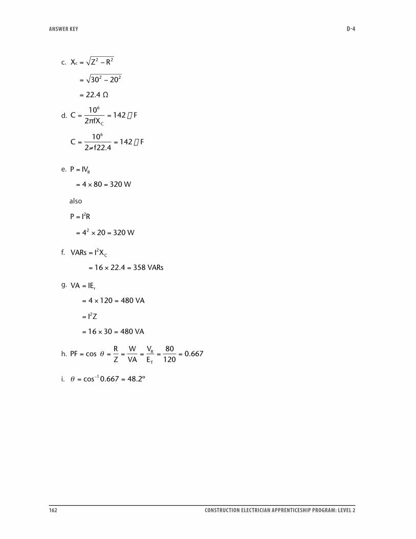
ANSwER kEY D-4
162 CONSTRUCTION ELECTRICIAN APPRENTICESHIP PROGRAM: LEVEL 2
c. X Z Rc = −
= −
=
2 2
2 230 20
22 4. Ω
d. CfX
F
Cf
C
= =
= =
102
142
102 22 4
142
6
6
π
F
≠
.
e. P IV
W
R=
= × =4 80 320
also
P I R
W
=
= × =
2
24 20 320
f. VARs I X
VARs
C=
= × =
2
16 22 4 358.
g. VA IE
VA
I Z
VA
r=
= × =
=
= × =
4 120 480
16 30 480
2
h. PFRZ
WVA
VE
R
T
= = = = = =cos .θ80
1200 667
i. θ = =−cos . . º10 667 48 2
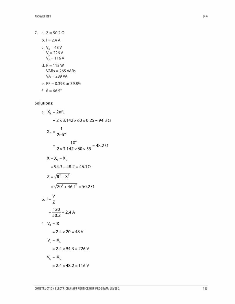
ANSwER kEY D-4
CONSTRUCTION ELECTRICIAN APPRENTICESHIP PROGRAM: LEVEL 2 163
7. a. Z = 50.2 Ω
b. I = 2.4 A
c. VR = 48 V VL= 226 V VC = 116 V
d. P = 115 W VARs = 265 VARs VA = 289 VA
e. PF = 0.398 or 39.8%
f. θ = 66.5°
Solutions:
a. X fL
XfC
L
C
=
= × × × =
=
=×
2
2 3 142 60 0 25 94 3
12
102 3 14
6
π
Ω
π
. . .
. 22 60 5548 2
× ×= . Ω
X X X
Z R X
L C= −
= − =
= +
= + =
94 3 48 2 46 1
20 46 1 50 2
2 2
2 2
. . .
. .
Ω
Ω
b. IVZ
A
=
= =12050 2
2 4.
.
c. V IR
V
V IX
V
V IX
R
L L
C C
=
= × =
=
= × =
=
= ×
2 4 20 48
2 4 94 3 226
2 4
.
. .
. 448 2 116. = V
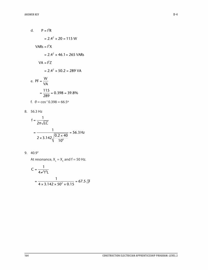
ANSwER kEY D-4
164 CONSTRUCTION ELECTRICIAN APPRENTICESHIP PROGRAM: LEVEL 2
d. P I R
W
VARs I X
VARs
VA
=
= × =
=
= × =
=
2
2
2
2
2 4 20 115
2 4 46 1 265
.
. .
II Z
VA
2
22 4 50 2 289= × =. .
e. PFWVA
=
= = =115289
0 398 39 8. . %
f. θ = cos-1 0.398 = 66.5º
8. 56.3 Hz
fLC
Hz
=
=
××
=
12
1
2 3 1420 2 40
10
56 3
6
π
..
.
9. 40.9°
At resonance, XL = XC and f = 50 Hz.
Cf L
F
=
=× × ×
=
14
14 3 142 50 0 15
67 5
2 2
2
≠
. .
.
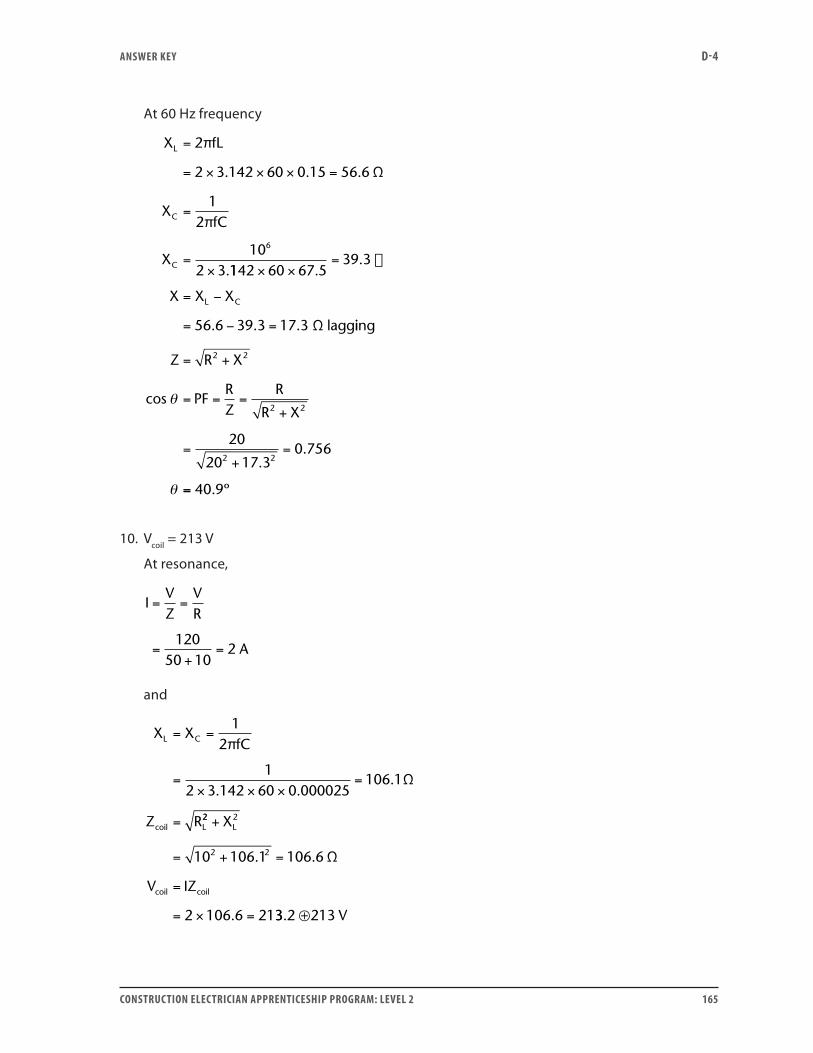
ANSwER kEY D-4
CONSTRUCTION ELECTRICIAN APPRENTICESHIP PROGRAM: LEVEL 2 165
At 60 Hz frequency
X fL
XfC
X
L
C
C
=
= × × × =
=
=×
2
2 3 142 60 0 15 56 6
12
102 3
6
π
Ω
π
. . .
.1142 60 67 539 3
56 6 39 3 17 3
× ×=
= −
= − =
..
. . .
X X XL C
Ω laggiing
Z R X2 2= +
= = =+
=+
=
cos
..
θ
θ
PFRZ
R
R X2 2
2 2
20
20 17 30 756
== 40 9. º
10. Vcoil = 213 V
At resonance,
IVZ
VR
A
= =
=+
=120
50 102
and
X XfC
Z R
L C
coil L
= =
=× × ×
=
=
12
12 3 142 60 0 000025
106 1
π
Ω. .
.
22 2
2 210 106 1 106 6
2 106 6 21
+
= + =
=
= × =
X
V IZ
L
coil coil
. .
.
Ω
33 2 213. ⊕ V
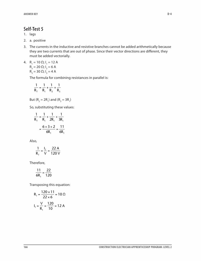
ANSwER kEY D-4
166 CONSTRUCTION ELECTRICIAN APPRENTICESHIP PROGRAM: LEVEL 2
Self-Test 51. lags
2. a. positive
3. The currents in the inductive and resistive branches cannot be added arithmetically because they are two currents that are out of phase. Since their vector directions are different, they must be added vectorially.
4. R1 = 10 Ω; I1 = 12 A R2 = 20 Ω; I2 = 6 A R3 = 30 Ω; I3 = 4 A
The formula for combining resistances in parallel is:
1 1 1 1
1 2 3R R R RT
= + +
But (R2 = 2R1) and (R3 = 3R1)
So, substituting these values:
1 1 12
13
6 3 26
116
1 1 1
1 1
R R R R
R R
T
= + +
=+ +
=
Also,
1RT
= =IV
AV
T 22120
Therefore,
116R1
=22
120
Transposing this equation:
R
IVR
A
1
11
120 1122 6
10
12010
12
=×
×=
= = =
Ω
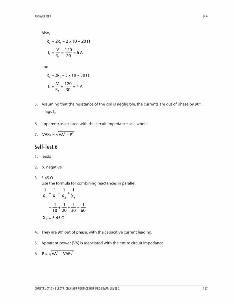
ANSwER kEY D-4
CONSTRUCTION ELECTRICIAN APPRENTICESHIP PROGRAM: LEVEL 2 167
Also,
R R
IVR
A
2 1
22
2 2 10 20
12020
6
= = × =
= = =
Ω
and
R R
IVR
A
3 1
33
3 3 10 30
12030
4
= = × =
= = =
Ω
5. Assuming that the resistance of the coil is negligible, the currents are out of phase by 90°.
IL lags IR.
6. apparent; associated with the circuit impedance as a whole
7. VARs VA P= −2 2
Self-Test 61. leads
2. b. negative
3. 5.45 Ω Use the formula for combining reactances in parallel:
1 1 1 1
110
120
130
160
5 45
1 2 3X X X X
X
T
T
= + +
= + + =
= . Ω
4. They are 90° out of phase, with the capacitive current leading.
5. Apparent power (VA) is associated with the entire circuit impedance.
6. P VA VARs= −2 2
ANSwER kEY D-4
168 CONSTRUCTION ELECTRICIAN APPRENTICESHIP PROGRAM: LEVEL 2
Self-Test 71. because voltage is the same across all branches of a parallel circuit
2. in the resistance of the circuit
3. 180°
4. b. False The net VARs is developed in the inductive and capacitive branches combined.
5. a. leading
6. d. Increase the value of capacitance (C).
7. The coil usually has some resistance, so the inductive branch has an impedance rather than a pure reactance.
Self-Test 81. a. V = 60 V
b. IT = 15.3 A
c. IL = 3.2 A
d. Z = 3.9 Ω
e. XL = 18.9 Ω
f. PF = 98%, lagging
g. θ = 11.5°
Solutions:The line voltage is the same as the voltage across the resistor:
a. V I R VR= = × =15 4 60
One fairly simple way to calculate these answers follows. The answers are not calculated in the same order as the questions. Use other equations to check the answers where you can.
e. X fLL = = × × × =2 2 3 142 60 0 05 18 9π Ω. . .
c. IVX
ALL
= = =60
18 93 2
..
b. I I I AT R L= + = + =2 2 2 215 3 2 15 3. .
ANSwER kEY D-4
CONSTRUCTION ELECTRICIAN APPRENTICESHIP PROGRAM: LEVEL 2 169
d. ZVIT
= = =60
15 33 9
.. Ω
f. PFIIR
T
= = = =15
15 30 98 98
.. %
g. θ = =−cos 1 0 98 11 5. . º
2. a. IR = 6 A
b. IL = 8 A
c. IT = 10 A
d. PF = 60%
e. Z = 12 Ω
f. P = 720 W
g. VARs = 960 VARs
h. VA = 1200 VA
Solutions:
Use Ohm’s law for IR and IL.
a. IVR
AR = = =12020
6
b. IVX
ALL
= = =12015
8
c. Combine these two vectors to find IT:
I I I AT R L= + = + =2 2 2 26 8 10
From this:
d. PFIIR
T
= = = =6
100 6 60. %
and
e. ZVIT
= = =12010
12 Ω
Now, use the calculated current values in the power equations:
f. P I V WR= = × =6 120 720
g. VARs I V VARsL= = × =8 120 960
h. VA I V VAT= = × =10 120 1200
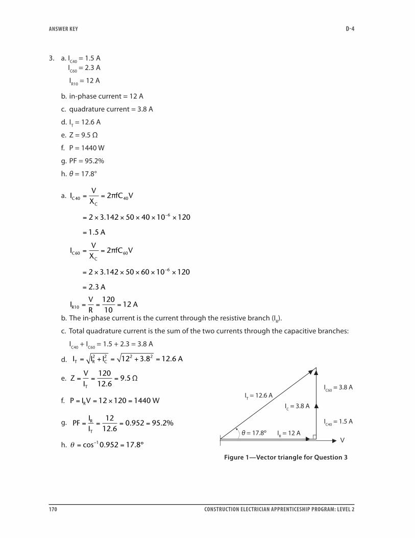
ANSwER kEY D-4
170 CONSTRUCTION ELECTRICIAN APPRENTICESHIP PROGRAM: LEVEL 2
3. a. IC40 = 1.5 A IC60 = 2.3 A
IR10 = 12 A
b. in-phase current = 12 A
c. quadrature current = 3.8 A
d. IT = 12.6 A
e. Z = 9.5 Ω
f. P = 1440 W
g. PF = 95.2%
h. θ = 17.8°
a. IVX
fC V
A
CC
40 40
6
2
2 3 142 50 40 10 120
1 5
= =
= × × × × ×
=
−
π
.
.
IVX
fC V
A
CC
60 60
6
2
2 3 142 50 60 10 120
2 3
= =
= × × × × ×
=
−
π
.
.
IVR
AR10
12010
12= = =
b. The in-phase current is the current through the resistive branch (IR).
c. Total quadrature current is the sum of the two currents through the capacitive branches:
IC40 + IC60 = 1.5 + 2.3 = 3.8 A
d. I I I AT R C= + = + =2 2 2 212 3 8 12 6. .
e. ZVIT
= = =12012 6
9 5.
. Ω
f. P I V WR= = × =12 120 1440
g. PFIIR
T
= = = =12
12 60 952 95 2
.. . %
h. θ = =−cos . . º10 952 17 8
IC40 = 1.5 A
IR = 12 A
IC = 3.8 A
IT = 12.6 AIC60 = 3.8 A
θ = 17.8º
Figure 1—Vector triangle for Question 3
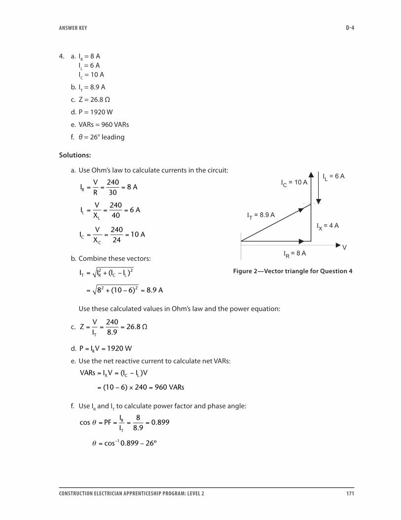
ANSwER kEY D-4
CONSTRUCTION ELECTRICIAN APPRENTICESHIP PROGRAM: LEVEL 2 171
4. a. IR = 8 A IL = 6 A IC = 10 A
b. IT = 8.9 A
c. Z = 26.8 Ω
d. P = 1920 W
e. VARs = 960 VARs
f. θ = 26° leading
Solutions:
a. Use Ohm’s law to calculate currents in the circuit:
IVR
A
IVX
A
IVX
A
R
LL
CC
= = =
= = =
= = =
24030
8
24040
6
24024
10
b. Combine these vectors:
I I I I
A
T R C L= + −
= + − =
2 2
2 28 10 6 8 9
( )
( ) .
Use these calculated values in Ohm’s law and the power equation:
c. ZVIT
= = =2408 9
26 8.
. Ω
d. P I V WR= = 1920
e. Use the net reactive current to calculate net VARs:
VARs I V I I V
VARs
X C L= = −
= − × =
( )
( )10 6 240 960
f. Use IR and IT to calculate power factor and phase angle:
cos PFIIR
T
θ
θ
= = = =
= −−
88 9
0 899
0 899 261
..
cos . º
Figure 2—Vector triangle for Question 4
ANSwER kEY D-4
172 CONSTRUCTION ELECTRICIAN APPRENTICESHIP PROGRAM: LEVEL 2
5. b. circuit resistance
6. a. True
7. They are equal in size. The capacitor supplies all the magnetizing VARs required by the coil.
8. 23.2 µF
21
2
14
14 3 142 60 0 3
0 0000232
2 2 2 2
ππ
π
fLfC
Cf L
=
= =× × ×
=
. .
. FF = 23 2. F
9. In parallel resonance, line current is at a minimum; in series resonance, it is at a maximum.
10. 2.1 A
X X fL
IVX
C L
LL
= =
= × × × −
= = =
2
2 3 142 60 0 15 56 6
12056 6
π
Ω. . .
.22 1
2 1
.
.
A
I I AC L= =
11. a. IT = 51 A
b. Z = 10.8 Ω
c. PF = 98%
d. C = 48 µF
Solutions:
a. Use Ohm’s law to calculate branch currents:
IVR
A
IVX
A
R
LL
= = =
= = =
55011
50
55055
10
ANSwER kEY D-4
CONSTRUCTION ELECTRICIAN APPRENTICESHIP PROGRAM: LEVEL 2 173
Combine these vectors:
I I I
A
T R L= +
= + = ⊕
2 2
2 250 10 50 8 51.
b. Use Ohm’s law again to calculate impedance:
Z
VIT
= = =55051
10 8. Ω
c. Use current values to calculate the power factor:
PF
IIR
T
= = = =5051
0 98 98. %
d. At resonance, the power factor is 100% and XL = XC = 55 Ω:
CfX
F F F
C
= =× × ×
= = ⊕
12
12 3 142 60 55
0 0000482 48 2 48
π .
. .
12. Line current = 8.35 A Circuit power factor = 96% True power dissipated in the resistive branch is
PVR
WR = = =2 2120
25576 .
Some true power is also dissipated in the resistance of the coil. This resistance is
R Z PFL L L= × = × =30 0 8 24. Ω.
Current through this coil is
IVZ
AL = = =12030
4 .
Power dissipated in the coil’s resistance is
P I R WL L L= × = × =2 24 24 384 .
Total true power in this circuit is
P P P WT R L= + = + =576 384 960 .
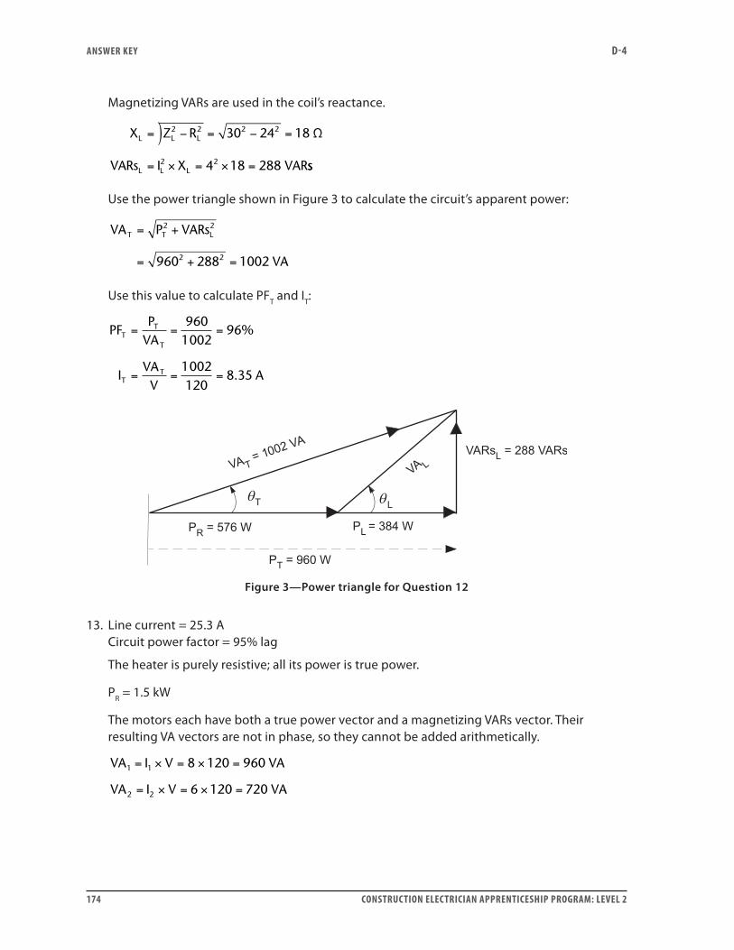
ANSwER kEY D-4
174 CONSTRUCTION ELECTRICIAN APPRENTICESHIP PROGRAM: LEVEL 2
Magnetizing VARs are used in the coil’s reactance.
)X Z R
VARs I X VAR
L L L
L L L
= − = − =
= × = × =
2 2 2 2
2 2
30 24 18
4 18 288
Ω
ss
Use the power triangle shown in Figure 3 to calculate the circuit’s apparent power:
VA P VARs
VA
T T L= +
= + =
2 2
2 2960 288 1002
Use this value to calculate PFT and IT:
PFP
VA
IVAV
A
TT
T
TT
= = =
= = =
9601002
96
1002120
8 35
%
.
Figure 3—Power triangle for Question 12
13. Line current = 25.3 A Circuit power factor = 95% lag
The heater is purely resistive; all its power is true power.
PR = 1.5 kW
The motors each have both a true power vector and a magnetizing VARs vector. Their resulting VA vectors are not in phase, so they cannot be added arithmetically.
VA I V VA
VA I V VA
1 1
2 2
8 120 960
6 120 720
= × = × =
= × = × =
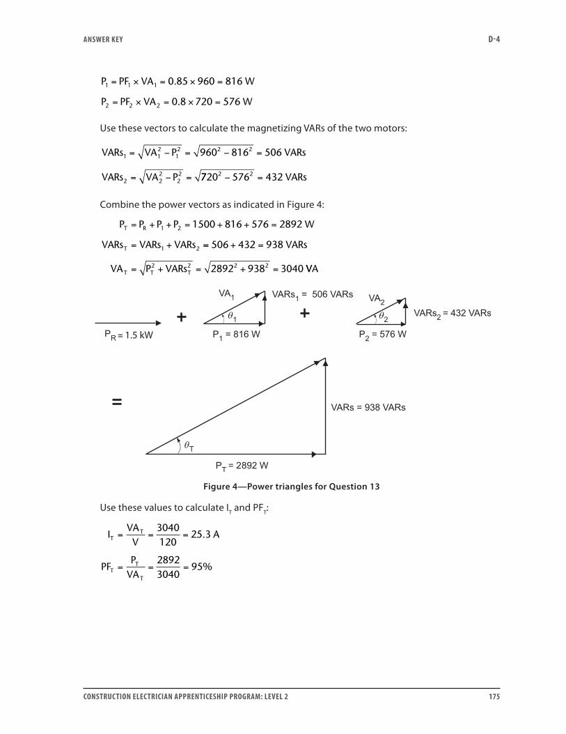
ANSwER kEY D-4
CONSTRUCTION ELECTRICIAN APPRENTICESHIP PROGRAM: LEVEL 2 175
P PF VA W
P PF VA W
1 1 1
2 2 2
0 85 960 816
0 8 720 576
= × = × =
= × = × =
.
.
Use these vectors to calculate the magnetizing VARs of the two motors:
VARs VA P VARs
VARs VA P
1 12
12 2 2
2 22
22
960 816 506= − = − =
= − = 7720 576 4322 2− = VARs
Combine the power vectors as indicated in Figure 4:
P P P P W
VARs VARs VARs
T R
T
= + + = + + =
= +
1 2
1 2
1500 816 576 2892
== + =
= + = + =
506 432 938
2892 938 30402 2 2 2
VARs
VA P VARsT T T VVA
1.5 kW
Figure 4—Power triangles for Question 13
Use these values to calculate IT and PFT:
IVAV
A
PFP
VA
TT
TT
T
= = =
= = =
3040120
25 3
28923040
95
.
%

ANSwER kEY D-4
176 CONSTRUCTION ELECTRICIAN APPRENTICESHIP PROGRAM: LEVEL 2
Self-Test 91. Any two of the following:
• Induction motors
• Fluorescent
• Other ballast lighting
• Electric arc welders
2. a. 100%
(Remember, a high value of power factor—whether expressed as a percent or as a decimal—is good, and a low value is poor.)
3. • To avoid paying a penalty to the utility company for the true power you use.
• To effectively increase the amount of true power that can be delivered, without exceeding the ampacity of the conductors.
• To increase the efficiency with which a given amount of true power can be delivered, by reducing the line losses.
4. by adding too much capacitance (This may lead to an excessive amount of capacitive current.)
5. • A risk of overcorrection may arise for a number of reasons (including load fluctuations).
• It is costly to use extra capacitors unnecessarily.
6. c. are unaffected
Self-Test 101. b. parallel
2. b. low opposition to current flow
3. d. avoided at all costs
4. a. a large single-induction induction motor load that is frequently turned on and off
5. c. The cumulative effect of hundreds of uncorrected ballasts becomes important.
6. d. unswitched

ANSwER kEY D-4
CONSTRUCTION ELECTRICIAN APPRENTICESHIP PROGRAM: LEVEL 2 177
7. c. where all the motors are small, about the same size and fed from a common motor-control centre
8. b. by switches that facilitate maintenance
9. voltage, frequency and kVARs rating; the phase
10. a. voltage
11. b. fall
12. b. fall
13. b. 26 A
14. b. 6.3 kVARs
15. d. The VARs will go down and the current will go down.
16. a. 14.7 A
17. b. 8.1 kVARs
Self-Test 111. b. power triangle
2. d. kW divided by kVA
3. c. 125 kW
4. b. 2000 kVA
5. a. 18°
6. b. 73%
7. c. 3775 VARs = 3.775 kVARs
8. b. 361 VA
9. d. 388 kVARs
10. b. 693 kVARs

ANSwER kEY D-4
178 CONSTRUCTION ELECTRICIAN APPRENTICESHIP PROGRAM: LEVEL 2
11. b. 3.45 kVARs
12. 20.8 A
13. c. 5 A
14. c. 520 kVARs
15. a. 0.44
16. c. When the power factor of a load is corrected, the load itself draws the same number of watts, volt-amps and VARs as it did before.
17. d. You may not be able to purchase a capacitor for industrial power factor correction of the size you calculated, so a compromise may be necessary.
18. b. 32.4 kVA
19. a. 16.2 kW
20. c. 28.1 kVARs
21. d. 117.0 A
22. b. 427 kVARs
23. c. 0.70
24. c. 447 kVARs
25. b. 740 kVARs
26. a. 75 kVARs
27. c. 572 kVARs
28. c. 0.72
29. a. a rise in the kVARs in the capacitor
30. c. fall
31. b. 10.9 kVARs
32. c. 22.7 A
33. c. 21.8 A


ISBN 978-0-7726-6410-5
9 780772 6641057960003429