Embed Size (px)
Citation preview

New Mexico State University1780 E University AveLas Cruces, NM 88003
BID LOT 1 – NMSU Agricultural Modernization: Food Science Learning and Safety Facility80% CONSTRUCTION DOCUMENTS Intermediate Submittal Option 1 Changes
PROJECT MANUAL- VOLUME 2Date: January 12, 2021
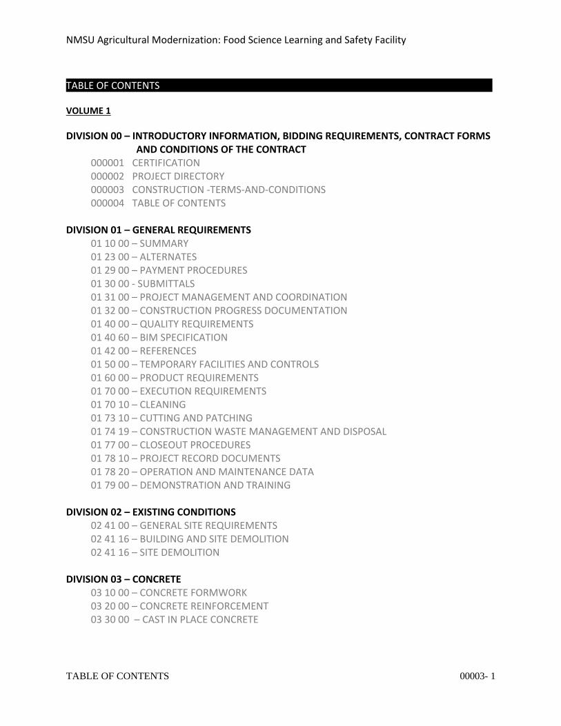
NMSU Agricultural Modernization: Food Science Learning and Safety Facility
TABLE OF CONTENTS 00003- 1
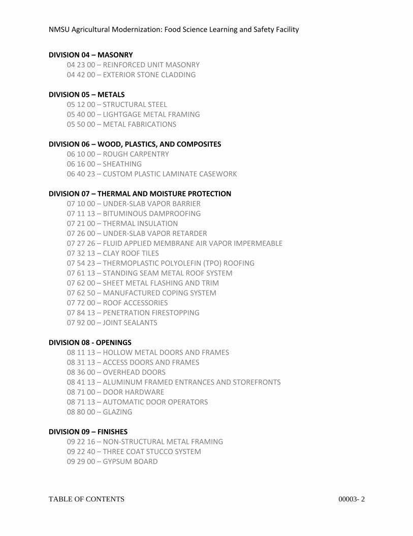
TABLE OF CONTENTS VOLUME 1
DIVISION 00 – INTRODUCTORY INFORMATION, BIDDING REQUIREMENTS, CONTRACT FORMS AND CONDITIONS OF THE CONTRACT
000001 CERTIFICATION 000002 PROJECT DIRECTORY 000003 CONSTRUCTION -TERMS-AND-CONDITIONS 000004 TABLE OF CONTENTS
DIVISION 01 – GENERAL REQUIREMENTS 01 10 00 – SUMMARY 01 23 00 – ALTERNATES 01 29 00 – PAYMENT PROCEDURES 01 30 00 - SUBMITTALS 01 31 00 – PROJECT MANAGEMENT AND COORDINATION 01 32 00 – CONSTRUCTION PROGRESS DOCUMENTATION 01 40 00 – QUALITY REQUIREMENTS 01 40 60 – BIM SPECIFICATION 01 42 00 – REFERENCES 01 50 00 – TEMPORARY FACILITIES AND CONTROLS 01 60 00 – PRODUCT REQUIREMENTS 01 70 00 – EXECUTION REQUIREMENTS 01 70 10 – CLEANING 01 73 10 – CUTTING AND PATCHING 01 74 19 – CONSTRUCTION WASTE MANAGEMENT AND DISPOSAL 01 77 00 – CLOSEOUT PROCEDURES 01 78 10 – PROJECT RECORD DOCUMENTS 01 78 20 – OPERATION AND MAINTENANCE DATA 01 79 00 – DEMONSTRATION AND TRAINING
DIVISION 02 – EXISTING CONDITIONS 02 41 00 – GENERAL SITE REQUIREMENTS 02 41 16 – BUILDING AND SITE DEMOLITION 02 41 16 – SITE DEMOLITION
DIVISION 03 – CONCRETE
03 10 00 – CONCRETE FORMWORK 03 20 00 – CONCRETE REINFORCEMENT 03 30 00 – CAST IN PLACE CONCRETE
NMSU Agricultural Modernization: Food Science Learning and Safety Facility
TABLE OF CONTENTS 00003- 2
DIVISION 04 – MASONRY 04 23 00 – REINFORCED UNIT MASONRY 04 42 00 – EXTERIOR STONE CLADDING
DIVISION 05 – METALS
05 12 00 – STRUCTURAL STEEL 05 40 00 – LIGHTGAGE METAL FRAMING 05 50 00 – METAL FABRICATIONS
DIVISION 06 – WOOD, PLASTICS, AND COMPOSITES
06 10 00 – ROUGH CARPENTRY 06 16 00 – SHEATHING 06 40 23 – CUSTOM PLASTIC LAMINATE CASEWORK
DIVISION 07 – THERMAL AND MOISTURE PROTECTION
07 10 00 – UNDER-SLAB VAPOR BARRIER 07 11 13 – BITUMINOUS DAMPROOFING 07 21 00 – THERMAL INSULATION 07 26 00 – UNDER-SLAB VAPOR RETARDER 07 27 26 – FLUID APPLIED MEMBRANE AIR VAPOR IMPERMEABLE 07 32 13 – CLAY ROOF TILES 07 54 23 – THERMOPLASTIC POLYOLEFIN (TPO) ROOFING 07 61 13 – STANDING SEAM METAL ROOF SYSTEM 07 62 00 – SHEET METAL FLASHING AND TRIM 07 62 50 – MANUFACTURED COPING SYSTEM 07 72 00 – ROOF ACCESSORIES 07 84 13 – PENETRATION FIRESTOPPING 07 92 00 – JOINT SEALANTS
DIVISION 08 - OPENINGS
08 11 13 – HOLLOW METAL DOORS AND FRAMES 08 31 13 – ACCESS DOORS AND FRAMES 08 36 00 – OVERHEAD DOORS 08 41 13 – ALUMINUM FRAMED ENTRANCES AND STOREFRONTS 08 71 00 – DOOR HARDWARE 08 71 13 – AUTOMATIC DOOR OPERATORS 08 80 00 – GLAZING
DIVISION 09 – FINISHES
09 22 16 – NON-STRUCTURAL METAL FRAMING 09 22 40 – THREE COAT STUCCO SYSTEM 09 29 00 – GYPSUM BOARD
NMSU Agricultural Modernization: Food Science Learning and Safety Facility
TABLE OF CONTENTS 00003- 3
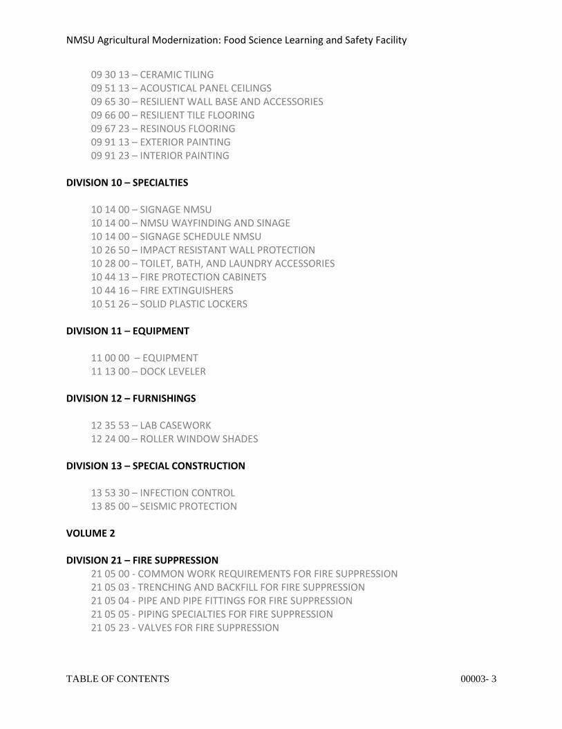
09 30 13 – CERAMIC TILING 09 51 13 – ACOUSTICAL PANEL CEILINGS 09 65 30 – RESILIENT WALL BASE AND ACCESSORIES 09 66 00 – RESILIENT TILE FLOORING 09 67 23 – RESINOUS FLOORING 09 91 13 – EXTERIOR PAINTING 09 91 23 – INTERIOR PAINTING
DIVISION 10 – SPECIALTIES
10 14 00 – SIGNAGE NMSU 10 14 00 – NMSU WAYFINDING AND SINAGE 10 14 00 – SIGNAGE SCHEDULE NMSU 10 26 50 – IMPACT RESISTANT WALL PROTECTION 10 28 00 – TOILET, BATH, AND LAUNDRY ACCESSORIES 10 44 13 – FIRE PROTECTION CABINETS 10 44 16 – FIRE EXTINGUISHERS 10 51 26 – SOLID PLASTIC LOCKERS
DIVISION 11 – EQUIPMENT 11 00 00 – EQUIPMENT 11 13 00 – DOCK LEVELER DIVISION 12 – FURNISHINGS
12 35 53 – LAB CASEWORK 12 24 00 – ROLLER WINDOW SHADES
DIVISION 13 – SPECIAL CONSTRUCTION 13 53 30 – INFECTION CONTROL 13 85 00 – SEISMIC PROTECTION VOLUME 2 DIVISION 21 – FIRE SUPPRESSION
21 05 00 - COMMON WORK REQUIREMENTS FOR FIRE SUPPRESSION 21 05 03 - TRENCHING AND BACKFILL FOR FIRE SUPPRESSION 21 05 04 - PIPE AND PIPE FITTINGS FOR FIRE SUPPRESSION 21 05 05 - PIPING SPECIALTIES FOR FIRE SUPPRESSION 21 05 23 - VALVES FOR FIRE SUPPRESSION
NMSU Agricultural Modernization: Food Science Learning and Safety Facility
TABLE OF CONTENTS 00003- 4
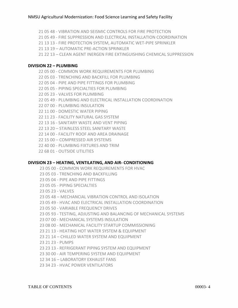
21 05 48 - VIBRATION AND SEISMIC CONTROLS FOR FIRE PROTECTION 21 05 49 - FIRE SUPPRESSION AND ELECTRICAL INSTALLATION COORDINATION 21 13 13 - FIRE PROTECTION SYSTEM, AUTOMATIC WET-PIPE SPRINKLER 21 13 19 – AUTOMATIC PRE-ACTION SPRINKLER 21 22 13 – CLEAN AGENT INERGEN FIRE EXTINGUISHING CHEMICAL SUPPRESSION
DIVISION 22 – PLUMBING
22 05 00 - COMMON WORK REQUIREMENTS FOR PLUMBING 22 05 03 - TRENCHING AND BACKFILL FOR PLUMBING 22 05 04 - PIPE AND PIPE FITTINGS FOR PLUMBING 22 05 05 - PIPING SPECIALTIES FOR PLUMBING 22 05 23 - VALVES FOR PLUMBING 22 05 49 - PLUMBING AND ELECTRICAL INSTALLATION COORDINATION 22 07 00 - PLUMBING INSULATION 22 11 00 - DOMESTIC WATER PIPING 22 11 23 - FACILITY NATURAL GAS SYSTEM 22 13 16 - SANITARY WASTE AND VENT PIPING 22 13 20 – STAINLESS STEEL SANITARY WASTE 22 14 00 - FACILITY ROOF AND AREA DRAINAGE 22 15 00 – COMPRESSED AIR SYSTEMS 22 40 00 - PLUMBING FIXTURES AND TRIM 22 68 01 - OUTSIDE UTILITIES
DIVISION 23 – HEATING, VENTILATING, AND AIR- CONDITIONING
23 05 00 - COMMON WORK REQUIREMENTS FOR HVAC 23 05 03 - TRENCHING AND BACKFILLING 23 05 04 - PIPE AND PIPE FITTINGS 23 05 05 - PIPING SPECIALTIES 23 05 23 - VALVES 23 05 48 – MECHANCIAL VIBRATION CONTROL AND ISOLATION 23 05 49 - HVAC AND ELECTRICAL INSTALLATION COORDINATION 23 05 50 - VARIABLE FREQUENCY DRIVES 23 05 93 - TESTING, ADJUSTING AND BALANCING OF MECHANICAL SYSTEMS 23 07 00 - MECHANICAL SYSTEMS INSULATION 23 08 00 - MECHANICAL FACILITY STARTUP COMMISSIONING 23 21 13 - HEATING HOT WATER SYSTEM & EQUIPMENT 23 21 14 – CHILLED WATER SYSTEM AND EQUIPMENT 23 21 23 - PUMPS 23 23 13 - REFRIGERANT PIPING SYSTEM AND EQUIPMENT 23 30 00 - AIR TEMPERING SYSTEM AND EQUIPMENT 12 34 16 – LABORATORY EXHAUST FANS 23 34 23 - HVAC POWER VENTILATORS
NMSU Agricultural Modernization: Food Science Learning and Safety Facility
TABLE OF CONTENTS 00003- 5
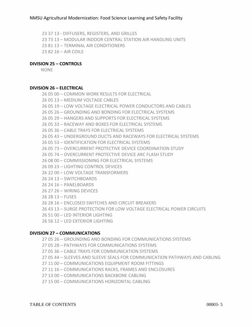
23 37 13 - DIFFUSERS, REGISTERS, AND GRILLES 23 73 13 – MODULAR INDOOR CENTRAL STATION AIR HANDLING UNITS 23 81 13 – TERMINAL AIR CONDITIONERS 23 82 16 – AIR COILS
DIVISION 25 – CONTROLS NONE DIVISION 26 – ELECTRICAL
26 05 00 – COMMON WORK RESULTS FOR ELECTRICAL 26 05 13 – MEDIUM VOLTAGE CABLES 26 05 19 – LOW VOLTAGE ELECTRICAL POWER CONDUCTORS AND CABLES 26 05 26 – GROUNDING AND BONDING FOR ELECTRICAL SYSTEMS 26 05 29 – HANGERS AND SUPPORTS FOR ELECTRICAL SYSTEMS 26 05 33 – RACEWAY AND BOXES FOR ELECTRICAL SYSTEMS 26 05 36 – CABLE TRAYS FOR ELECTRICAL SYSTEMS 26 05 43 – UNDERGROUND DUCTS AND RACEWAYS FOR ELECTRICAL SYSTEMS 26 05 53 – IDENTIFICATION FOR ELECTRICAL SYSTEMS 26 05 73 – OVERCURRENT PROTECTIVE DEVICE COORDINATION STUDY 26 05 74 – OVERCURRENT PROTECTIVE DEVICE ARC FLASH STUDY 26 08 00 – COMMISSIONING FOR ELECTRICAL SYSTEMS 26 09 23 – LIGHTING CONTROL DEVICES 26 22 00 – LOW VOLTAGE TRANSFORMERS 26 24 13 – SWITCHBOARDS 26 24 16 – PANELBOARDS 26 27 26 – WIRING DEVICES 26 28 13 – FUSES 26 28 16 – ENCLOSED SWITCHES AND CIRCUIT BREAKERS 26 43 13 – SURGE PROTECTION FOR LOW VOLTAGE ELECTRICAL POWER CIRCUITS 26 51 00 – LED INTERIOR LIGHTING
26 56 12 – LED EXTERIOR LIGHTING
DIVISION 27 – COMMUNICATIONS 27 05 26 – GROUNDING AND BONDING FOR COMMUNICATIONS SYSTEMS 27 05 28 – PATHWAYS FOR COMMUNICATIONS SYSTEMS 27 05 36 – CABLE TRAYS FOR COMMUNICATION SYSTEMS 27 05 44 – SLEEVES AND SLEEVE SEALS FOR COMMUNICATION PATHWAYS AND CABLING 27 11 00 – COMMUNICATIONS EQUIPMENT ROOM FITTINGS 27 11 16 – COMMUNICATIONS RACKS, FRAMES AND ENCLOSURES 27 13 00 – COMMUNICATIONS BACKBONE CABLING 27 15 00 – COMMUNICATIONS HORIZONTAL CABLING
NMSU Agricultural Modernization: Food Science Learning and Safety Facility
TABLE OF CONTENTS 00003- 6
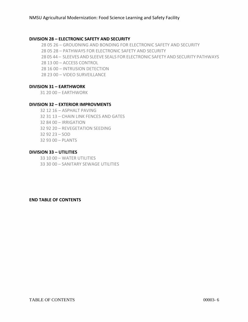
DIVISION 28 – ELECTRONIC SAFETY AND SECURITY
28 05 26 – GROUDNING AND BONDING FOR ELECTRONIC SAFETY AND SECURITY 28 05 28 – PATHWAYS FOR ELECTRONIC SAFETY AND SECURITY 28 05 44 – SLEEVES AND SLEEVE SEALS FOR ELECTRONIC SAFETY AND SECURITY PATHWAYS 28 13 00 – ACCESS CONTROL 28 16 00 – INTRUSION DETECTION 28 23 00 – VIDEO SURVEILLANCE
DIVISION 31 – EARTHWORK 31 20 00 – EARTHWORK DIVISION 32 – EXTERIOR IMPROVMENTS 32 12 16 – ASPHALT PAVING 32 31 13 – CHAIN LINK FENCES AND GATES 32 84 00 – IRRIGATION 32 92 20 – REVEGETATION SEEDING 32 92 23 – SOD 32 93 00 – PLANTS DIVISION 33 – UTILITIES 33 10 00 – WATER UTILITIES 33 30 00 – SANITARY SEWAGE UTILITIES END TABLE OF CONTENTS
NMSU Agricultural Modernization: Food Science Learning and Safety Facility
COMMON WORK REQUIREMENTS FOR FIRE SUPPRESSION 210500 - 1
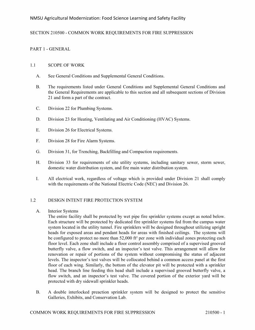
SECTION 210500 - COMMON WORK REQUIREMENTS FOR FIRE SUPPRESSION
PART 1 - GENERAL
1.1 SCOPE OF WORK
A. See General Conditions and Supplemental General Conditions.
B. The requirements listed under General Conditions and Supplemental General Conditions and the General Requirements are applicable to this section and all subsequent sections of Division 21 and form a part of the contract.
C. Division 22 for Plumbing Systems.
D. Division 23 for Heating, Ventilating and Air Conditioning (HVAC) Systems.
E. Division 26 for Electrical Systems.
F. Division 28 for Fire Alarm Systems.
G. Division 31, for Trenching, Backfilling and Compaction requirements.
H. Division 33 for requirements of site utility systems, including sanitary sewer, storm sewer, domestic water distribution system, and fire main water distribution system.
I. All electrical work, regardless of voltage which is provided under Division 21 shall comply with the requirements of the National Electric Code (NEC) and Division 26.
1.2 DESIGN INTENT FIRE PROTECTION SYSTEM
A. Interior SystemsThe entire facility shall be protected by wet pipe fire sprinkler systems except as noted below. Each structure will be protected by dedicated fire sprinkler systems fed from the campus water system located in the utility tunnel. Fire sprinklers will be designed throughout utilizing upright heads for exposed areas and pendant heads for areas with finished ceilings. The systems will be configured to protect no more than 52,000 ft² per zone with individual zones protecting each floor level. Each zone shall include a floor control assembly comprised of a supervised grooved butterfly valve, a flow switch, and an inspector’s test valve. This arrangement will allow for renovation or repair of portions of the system without compromising the status of adjacent levels. The inspector’s test valves will be collocated behind a common access panel at the first floor of each wing. Similarly, the bottom of the elevator pit will be protected with a sprinkler head. The branch line feeding this head shall include a supervised grooved butterfly valve, a flow switch, and an inspector’s test valve. The covered portion of the exterior yard will be protected with dry sidewall sprinkler heads.
B. A double interlocked preaction sprinkler system will be designed to protect the sensitive Galleries, Exhibits, and Conservation Lab.
NMSU Agricultural Modernization: Food Science Learning and Safety Facility
COMMON WORK REQUIREMENTS FOR FIRE SUPPRESSION 210500 - 2
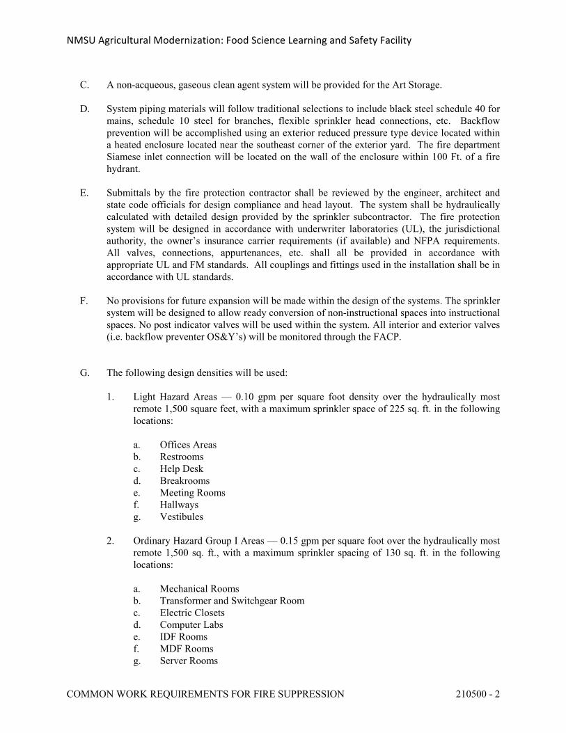
C. A non-acqueous, gaseous clean agent system will be provided for the Art Storage.
D. System piping materials will follow traditional selections to include black steel schedule 40 for mains, schedule 10 steel for branches, flexible sprinkler head connections, etc. Backflow prevention will be accomplished using an exterior reduced pressure type device located within a heated enclosure located near the southeast corner of the exterior yard. The fire department Siamese inlet connection will be located on the wall of the enclosure within 100 Ft. of a fire hydrant.
E. Submittals by the fire protection contractor shall be reviewed by the engineer, architect and state code officials for design compliance and head layout. The system shall be hydraulically calculated with detailed design provided by the sprinkler subcontractor. The fire protection system will be designed in accordance with underwriter laboratories (UL), the jurisdictional authority, the owner’s insurance carrier requirements (if available) and NFPA requirements. All valves, connections, appurtenances, etc. shall all be provided in accordance with appropriate UL and FM standards. All couplings and fittings used in the installation shall be in accordance with UL standards.
F. No provisions for future expansion will be made within the design of the systems. The sprinkler system will be designed to allow ready conversion of non-instructional spaces into instructional spaces. No post indicator valves will be used within the system. All interior and exterior valves (i.e. backflow preventer OS&Y’s) will be monitored through the FACP.
G. The following design densities will be used:
1. Light Hazard Areas — 0.10 gpm per square foot density over the hydraulically most remote 1,500 square feet, with a maximum sprinkler space of 225 sq. ft. in the following locations:
a. Offices Areasb. Restroomsc. Help Deskd. Breakroomse. Meeting Roomsf. Hallwaysg. Vestibules
2. Ordinary Hazard Group I Areas — 0.15 gpm per square foot over the hydraulically most remote 1,500 sq. ft., with a maximum sprinkler spacing of 130 sq. ft. in the following locations:
a. Mechanical Roomsb. Transformer and Switchgear Roomc. Electric Closetsd. Computer Labse. IDF Rooms f. MDF Roomsg. Server Rooms
NMSU Agricultural Modernization: Food Science Learning and Safety Facility
COMMON WORK REQUIREMENTS FOR FIRE SUPPRESSION 210500 - 3
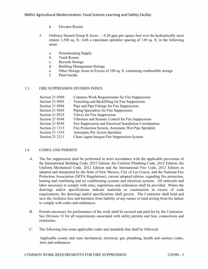
h. Elevator Rooms
3. Ordinary Hazard Group II Areas — 0.20 gpm per square foot over the hydraulically most remote 1,500 sq. ft., with a maximum sprinkler spacing of 130 sq. ft. in the following areas:
a. Housekeeping Supplyb. Trash Roomsc. Records Storaged. Building Management Storagee. Other Storage Areas in Excess of 100 sq. ft. containing combustible storagef. Paint booths
1.3 FIRE SUPPRESSION DIVISION INDEX
Section 21 0500 Common Work Requirements for Fire SuppressionSection 21 0503 Trenching and Backfilling for Fire SuppressionSection 21 0504 Pipe and Pipe Fittings for Fire SuppressionSection 21 0505 Piping Specialties for Fire SuppressionSection 21 0523 Valves for Fire SuppressionSection 21 0548 Vibration and Seismic Control for Fire Suppression Section 21 0549 Fire Suppression and Electrical Installation CoordinationSection 21 1313 Fire Protection System, Automatic Wet Pipe SprinklerSection 21 1319 Automatic Pre Action SprinklerSection 21 2213 Clean Agent Inergen Fire Suppression System
1.4 CODES AND PERMITS
A. The fire suppression shall be performed in strict accordance with the applicable provisions of the International Building Code, 2015 Edition; the Uniform Plumbing Code, 2012 Edition; the Uniform Mechanical Code, 2012 Edition and the International Fire Code, 2012 Edition as adopted and interpreted by the State of New Mexico, City of Las Cruces, and the National Fire Protection Association (NFPA Regulations), current adopted edition, regarding fire protection, heating and ventilating and air conditioning systems and electrical systems. All materials and labor necessary to comply with rules, regulations and ordinances shall be provided. Where the drawings and/or specifications indicate materials or construction in excess of code requirements, the drawings and/or specifications shall govern. The Contractor shall hold and save the Architect free and harmless from liability of any nature or kind arising from his failure to comply with codes and ordinances.
B. Permits necessary for performance of the work shall be secured and paid for by the Contractor. See Division 33 for all requirements associated with utility permits and fees, connections and extensions.
C. The following lists some applicable codes and standards that shall be followed.
Applicable county and state mechanical, electrical, gas, plumbing, health and sanitary codes, laws and ordinances
NMSU Agricultural Modernization: Food Science Learning and Safety Facility
COMMON WORK REQUIREMENTS FOR FIRE SUPPRESSION 210500 - 4
National Electrical Manufacturer's Association Standards
National Electrical Code
Underwriters Laboratories, Inc. Standards
American National Standards Institute
American Society for Testing Materials Standards
Standards and requirements of local utility companies
National Fire Protection Association Standards
American Society of Mechanical Engineers Boiler and Pressure Vessel Codes
Occupational Safety and Health Act
The American Society of Sanitary Engineering
1.5 RECORD DRAWINGS
A. See Division 1, for requirements associated with Project Record Drawings.
B. The Contractor shall be responsible to maintain a complete and accurate set of marked up blue-line prints showing information on the installed location and arrangement of all mechanical work, and in particular, where changes were made during construction. The Contractor shall be responsible for keeping record drawings accurate and up-to-date throughout the construction period. Record drawings may be reviewed and checked by the Architect during the construction and in conjunction with review and approval of monthly pay requests. The Contractor shall include copies of all addenda, RFI's, bulletins, and change orders neatly taped or attached to record drawing set.
C. After installation and acceptance of direct buried underground piping and service lines in trenches, the Contractor shall take 'as-built' measurements, including all depths, prior to commencement of backfilling operations. It will not be sufficient to check off line locations. Definite measurements shall be taken for each service line. The location of buried piping and trench service lines shall be shown on the drawings and dimensioned from fixed points.
1.6 QUALIFICATIONS
A. All mechanics shall be skilled in their respective trade.
B. All welders shall be certified in accordance with the ASME Boiler Test Code, Section IX, latest issue.
NMSU Agricultural Modernization: Food Science Learning and Safety Facility
COMMON WORK REQUIREMENTS FOR FIRE SUPPRESSION 210500 - 5
1.7 QUALIFICATION PROCEDURES
A. The storage, handling, and transportation of all refrigerants, oils, lubricants, etc. shall be accomplished in strict compliance with all State, local, and Federal Regulations including all requirements set forth by the Environmental Protection Agency (EPA) for the safe handling of regulated refrigerants and materials. The Contractor shall utilize qualified and/or certified personnel and equipment as prescribed by these requirements.
1.8 HAZARDOUS CONDITIONS
A. Protruding metal (bolts, steel angles, etc.) potentially hazardous to maintenance and operation personnel, shall be cut back and/or protected to reduce the risk of injury.
1.9 HAZARD SIGNS
A. Equipment rooms, fan plenums, and similar areas containing moving or rotating parts, or other potentially hazardous environments shall include signs on all doors entering such spaces that shall read similar to the following: "Hazardous Area - Authorized Personnel Only."
B. Confined Spaces: Areas designated by OSHA Standard 1910.146 as a confined space shall be marked with a sign that reads "Confined Space - Entry by authorized personnel only, by permit."
1. "Confined Space" means a space that:
a. Is large enough and so configured that an employee can bodily enter and perform assigned work; and
b. Has limited or restricted means for entry or exit (for example, tanks, vessels, storage bins, hoppers, vaults, and pits are spaces that may have limited means of entry); and
c. Is not designed for continuous employee occupancy.
C. The Contractor shall survey the final premises to determine where any such potentially hazardous areas exist. If the Contractor feels that hazards exist which cannot be suitably provided for through the above typical methods, he shall forward in writing his concerns, and request for a decision concerning the referenced hazard, prior to the final inspection of the facilities.
1.10 SUBMITTALS
A. The Contractor shall submit submittal brochures of all equipment, fixtures and materials to be furnished under Division 21, including but not limited to the following:
1. Piping materials, valves, equipment and installation methods, vibration isolation devices, pipe penetration installation methods and products for fire rated assemblies, and all equipment listed on equipment schedules, and in related construction documents.
2. Materials, certification, shop drawings, and other information as specified in the individual Division 21 Specification Sections within this Specification.
NMSU Agricultural Modernization: Food Science Learning and Safety Facility
COMMON WORK REQUIREMENTS FOR FIRE SUPPRESSION 210500 - 6
B. Unauthorized Substitutions: If substitute materials, equipment or systems are installed without prior review or are installed in a manner which is not in conformance with the requirement of this Specification and for which the Contractor has not received a written review, removal of all the unauthorized materials and installation of those indicated or specified shall be provided at no change in contract amount.
C. All equipment shall be installed in accordance with the manufacturer's recommendations. Provide all accessories and components for optimum operation as recommended by the manufacturer.
D. Expense: All costs for the preparation, correction, delivery, and return of the submittals shall be borne by the Contractor.
E. Submittals and one resubmittal will be reviewed by the Architect/Engineer. If the Contractor fails to provide the required data with his second submittal, he will be charged for the third and subsequent reviews.
F. See Division 1 for additional submission requirements.
G. Complete data must be furnished showing performance, quality and dimensions. No equipment or materials shall be purchased prior to receiving written notification that submittals have been reviewed and marked either "NO EXCEPTIONS TAKEN" or "EXCEPTIONS AS NOTED." Submittals returned marked "EXCEPTIONS AS NOTED" do not require resubmittal provided that the Contractor agrees to comply with all exceptions noted in the submittal, and so states in a letter.
H. Review of Submittals: Submittals will be reviewed with reasonable promptness, but only for conformance with the design concept of the Project and for conformance with the information indicated on the Drawings and stated in the Specifications. Review of a separate item as such will not indicate review of the assembly in which the item functions. Review of submittals shall not relieve the Contractor of responsibility for any deviation from the requirements of the Contract Documents, nor for errors or omissions in the submittals; or for the accuracy of dimensions and quantities, the adequacy of connections, and the proper and acceptable fitting, execution, functioning and completion of the work. Review shall not relieve the Contractor of responsibility for the equipment fitting within the allotted space shown on the drawings with all clearances required for equipment operation, service and maintenance including minimum clearances required by applicable codes, manufacturer's installation instructions and as necessary for proper clearance in front of all electrical panels as defined by the National Electric Code (NEC). Any relocation of mechanical and/or electrical equipment, materials and systems required to comply with minimum clearances shall be provided by the Contractor without additional cost under the Contract.
I. Shop drawings will be returned unchecked unless the following information is included: cover sheet shall be provided for each submittal of equipment, products and material proposed for use on the project. A common cover sheet for similar equipment (example: all air handling units or all fire protection products) is acceptable. The cover sheet shall list equipment by symbol number; reference all pertinent data in the Specifications or on the drawings; provide size and characteristics of the equipment, name of the project and a space large enough to accept a review stamp. The data submitted shall reflect the actual equipment performance under the
NMSU Agricultural Modernization: Food Science Learning and Safety Facility
COMMON WORK REQUIREMENTS FOR FIRE SUPPRESSION 210500 - 7
specified conditions and shall not be a copy of the scheduled data on the drawings. Cover sheet shall clearly identify any deviations from the specifications for submitted equipment, products, and materials.
J. Use of substitutions reviewed and checked by the Engineer does not relieve the Contractor from compliance with the Contract Documents. Contractor shall bear all extra expense resulting from the use of any substitutions where substitutions affect adjoining or related work required in this Division or other Divisions of this Specification.
K. If Contractor substitutes equipment for that drawn to scale on the drawings, he shall prepare a 1/4" = 1'-0" installation drawing for each equipment room where a substitution is made, using dimensions of substituted equipment, and including piping, and electrical equipment requirements, to verify that equipment will fit space with adequate clearances for maintenance. This 1/4" = 1'-0" fabrication drawing shall be submitted for review with the shop drawing submittals of the substitution. Failure to comply with this requirement will result in the shop drawings being returned unchecked.
1.11 COORDINATION DRAWINGS
A. The Contractor shall, in advance of the work, prepare coordination drawings for:
1. Mechanical equipment rooms.2. Piping and piping chases.3. Complete fire suppression system piping and sprinkler head layout.4. Layout of all fire suppression equipment.
B. Show the location of piping openings through the building floors, walls and roofs coordinated with Architectural and Structural, as well as the location and elevations of building fire suppression equipment and systems and piping, coordinated with plumbing, HVAC and electrical systems. Coordination drawings, including plans, elevations and sections, as appropriate, shall clearly show the manner in which the fire suppression systems fit into the available space and coordinates with HVAC and plumbing equipment, ductwork, piping, and electrical equipment, including conduits, light fixtures, motor control centers, transformers, panels, variable frequency drives, etc. Drawings shall demonstrate required code clearances for mechanical and electrical equipments, control panels, etc., and proper operation, maintenance and replacement of fire suppression devices and equipment. Coordination drawings shall be of appropriate scale to satisfy the previously stated purposes, but not smaller than 1/8 inch scale for floor plans and 1/4 scale of equipment rooms and chase areas. Drawings may be composite or may be separate but fully coordinated drawings of the same scale. Every subcontractor must sign-off on coordination drawings prepared by each craft. Failure to sign-off will indicate that subcontractor is proceeding at his own risk. Any cost required to relocate systems to comply with required clearance and equipment installation requirements shall be provided by the Contractor without additional cost under the contract.
C. Seven (7) complete sets of coordination drawings shall be submitted prior to the scheduled start of the work in the area illustrated by the drawings, for the purpose of showing the Contractor's planned method of installation. The objectives of such drawings are to promote carefully planned work sequence and proper coordination, in order to assure the expeditious solutions of problems, and the installation of lines and equipment as contemplated by the contract
NMSU Agricultural Modernization: Food Science Learning and Safety Facility
COMMON WORK REQUIREMENTS FOR FIRE SUPPRESSION 210500 - 8
documents while avoiding or minimizing additional costs to the Contractor and to the Owner.
D. In the event the Contractor, in coordinating the various installations and in planning the method of installation, finds a conflict in location or elevation of any of the mechanical systems, with the structural items or with other construction items, such conflicts shall immediately be documented and submitted for clarification. In doing so, the Contractor shall explain the proposed method of solving the problem, or shall request instructions as to how to proceed if adjustments beyond those of usual trades coordination are necessary.
E. Installation of fire suppression work shall not proceed prior to the submission and completion of the review of the coordination drawings, and any conflicts which are disclosed by the coordination drawings. It is the responsibility of the Contractor to submit the required drawings in a timely manner consistent with the requirements for completing the work covered by this contract within the prescribed contract time.
1.12 USE OF CADD FILES
A. Under certain conditions, the Contractor will be permitted the use of the Engineer's CADD files for documentation of as-builts, submittals, or coordination drawings.
B. The Engineer may require compensation for the time necessary to format the CADD files delivery to the Contractor. Such work will include removal of title blocks, professional for seals, calculations, proprietary information, etc.
C. The Contractor shall complete the enclosed License, Indemnity and Warranty Agreement, complete with contractor's name, address, and Contractor's Representative signature prior to request for CADD file usage.
1.13 PRIOR APPROVAL
A. Equipment manufacturers and service providers are listed within the specifications for the work specified in this division. For the items listed below, the specified manufacturers and providers are the only ones presently approved, and may be the only ones allowed:
1. Plumbing Fixtures and Trim2. Air Compressor3. Water Treatment Equipment
B. Manufacturers and service providers who are not listed in these specs, and who offer equivalent or superior products or services, are invited to submit for approval prior to bid (prior approval). Submit two copies. Requests for prior approval must:
1. Include the substitution request form at the end of this spec section.2. Include technical data sufficient for the Engineer to generally assess appropriateness for
this project.3. Be submitted minimum ten days prior to the bid date in effect at the time of submission.4. Comply with any additional requirements per specification Division 1.
NMSU Agricultural Modernization: Food Science Learning and Safety Facility
COMMON WORK REQUIREMENTS FOR FIRE SUPPRESSION 210500 - 9
C. Any additional prior approved alternate manufacturers and service providers will be published in an addendum prior to bid. Prior approval indicates that based on the information submitted it appears to the Engineer that the alternate might be capable of meeting the specifications and the design intent, and might be appropriate for the project. But prior approval does not guarantee this. Prior approved products and service providers must still go through the submittal process after award, and must still comply with the design intent and all specification requirements.
D. Please do not request prior approval for products and service providers that are not listed above. Instead, for those items alternate manufacturers and alternate service providers may be submitted after bid in accordance with the submittal process, provided they meet or exceed the specifications and the indicated design intent.
1.14 GUARANTEE-WARRANTY
A. See Division 1 for warranties.
B. The following guarantee is a part of the specifications and shall be binding on the Contractor:
"The Contractor guarantees that this installation is free from mechanical defects. He agrees to replace or repair any part of the installation which may fail within a period of one year after date established below, provided that such failure is due to defects in the materials or workmanship or to failure to follow the specifications and drawings. Warranty of the Contractor-furnished equipment or systems shall begin on the date the system or equipment is placed in operation for beneficial use of the Owner or occupancy by the Owner, whichever occurs first; such date will be determined in writing, by means of issuing a 'Certificate of Substantial Completion', AIA Form G704," or equivalent.
C. The extent of guarantees or warranties by Equipment and/or Materials Manufacturers shall not diminish the requirements of the Contractor's guarantee-warranty to the Owner.
D. All items of fire suppression equipment shall be provided with a full one (1) year parts and labor warranty, from the date of acceptance by the Owner.
PART 2 - PRODUCTS
2.1 QUALITY OF MATERIALS
A. All equipment and materials shall be new, and shall be the standard product of manufacturers regularly engaged in the production of fire suppression equipment and shall be the manufacturer's latest design. Specific equipment, shown in schedules on drawings and specified herein, is to set forth a standard of quality and operation.
B. Hazardous or Environmentally Damaging Materials: Products shall not contain asbestos, mercury, PCBs, or other materials harmful to people or the environment.
NMSU Agricultural Modernization: Food Science Learning and Safety Facility
COMMON WORK REQUIREMENTS FOR FIRE SUPPRESSION 210500 - 10
2.2 ELECTRICAL WIRING AND CONTROL EQUIPMENT
A. All wiring and conduit shall be furnished and installed as scheduled in Section 21 0549, Fire Suppression and Electrical Installation Coordination, unless otherwise noted or directed.
B. The Contractor shall coordinate completely with all trades and Sub-Contractors as required to ensure that all necessary components of control work are included and fully understood. No additional cost shall accrue to the Owner as a result of lack of such coordination.
C. The fire suppression piping system may be bonded to the electrical ground bus at the electrical service equipment, but shall not under any circumstances be used as the main grounding electrode for the electrical service.
2.3 PAINTING
A. All finish painting of fire suppression systems and equipment will be under "Painting," unless equipment is hereinafter specified to be provided with factory applied finish coats.
B. All equipment shall be provided with factory applied prime finish, unless otherwise specified.
C. Touch-Up: If the factory finish on any equipment is damaged in shipment or during construction of the building, the equipment shall be refinished.
2.4 IDENTIFICATION OF VALVES
A. Each valve shall be provided with a stamped metal tag secured to the valve. Tag shall indicate the valve number, the service and function of each valve and system valve numbers and designations shall be coordinated with existing valve identification. In addition, the Contractor shall provide a valve chart, typed neatly on 8-1/2" x 11" sheets, listing the number, size, location, function, normal operating position, on each valve installed under Division 21. Tags shall be stamped brass 1-1/2" diameter, and secured to valves by heavy copper figure eight hooks, braided stainless steel wire anchor, or other approved means.
B. Division 21 valve tags shall be coordinated with Division 22 and Division 23 valve tags for coordinated format between each division.
2.5 PIPING SYSTEM IDENTIFICATION
A. Means of Identification: All piping shall be identified by each of the means described below. The Contractor shall provide shop drawing submittal data for proposed labeling system materials and manufacturer's recommended installation procedures.
B. Piping Systems shall be identified by means of an identifying legend on color coded background appropriately worded to indicate the "service" name of the pipe as shown on the drawings. Color coded banding shall also be provided. Additionally, an arrow shall be included to indicate the direction of flow through the pipe.
NMSU Agricultural Modernization: Food Science Learning and Safety Facility
COMMON WORK REQUIREMENTS FOR FIRE SUPPRESSION 210500 - 11
C. Locations of Piping System Identification: The identifying legends and directional arrows described in the paragraphs preceding shall be located at the following points on each piping system:
Adjacent to each valve in piping system. At every point of entry and exit where piping passes through a wall. On each pipe riser and junction. At a maximum interval of 20 feet on pipe lines exposed and concealed above
accessible ceilings. Adjacent to all special fittings (regulating valves, etc.) in piping systems. At every access door.
D. Piping identification shall meet the standards of the Federal Occupational Safety Health Act (OSHA) which refers to the ANSI Standard A13.1. The following standardized color code scheme shall be used:
Yellow - Hazardous MaterialsGreen - Liquid Materials of Inherently Low HazardBlue - Gaseous Materials of Inherently Low HazardRed - Fire Protection Materials
E. The size of letter and length of color field shall conform to the ANSI standard and shall be as follows:
Outside Diameter of Length of Size of Pipe or Covering Color Field Letters
------ to 1-1/4" 8" 1/2"1-1/2" to 2" 8" 3/4"2-1/2" to 6" 12" 1-1/4"8" to 10" 24" 2-1/2"Over 10" 32" 3-1/2"
F. All pipe labels exposed within mechanical equipment spaces shall be semi-rigid plastic identification markers. Each label shall have appropriately color-coded background with printed legend. Directional flow arrows shall be included on label. Labels shall "snap-on" around pipe without the requirement for adhesive or bonding of piping sizes 3/4" through 5". Labels for piping 6" and larger shall be furnished with spring attachment at each end of label. Labels shall be "SETMARK" Type SNA, 3/4" through 5" size and Type STR, 6" and larger, as manufactured by Seton Name Plate Corporation, Brady, or equivalent.
G. All pipe labels except pipe labels located exposed within the mechanical equipment spaces shall be vinyl material with permanent adhesive for application to clear dry pipe and/or insulation jacketing. Each label shall have appropriate color-coded background with printed legend. Direction arrows shall be placed next to label to indicate flow direction. Color and size of arrows shall correspond to that of label. Pressure sensitive pipe tape matching the background color of the label shall be placed over each end of the label and completely around the pipe.
NMSU Agricultural Modernization: Food Science Learning and Safety Facility
COMMON WORK REQUIREMENTS FOR FIRE SUPPRESSION 210500 - 12
H. Attach pipe markers to lower quarter of the pipe on horizontal runs and on the centerline of vertical piping where view is not obstructed. Flow indicator arrow shall point away from pipe marker.
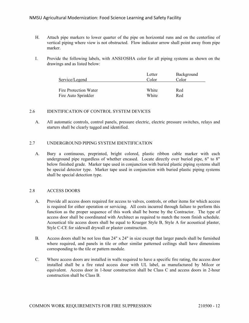
I. Provide the following labels, with ANSI/OSHA color for all piping systems as shown on the drawings and as listed below:
Letter BackgroundService/Legend Color Color
Fire Protection Water White RedFire Auto Sprinkler White Red
2.6 IDENTIFICATION OF CONTROL SYSTEM DEVICES
A. All automatic controls, control panels, pressure electric, electric pressure switches, relays and starters shall be clearly tagged and identified.
2.7 UNDERGROUND PIPING SYSTEM IDENTIFICATION
A. Bury a continuous, preprinted, bright colored, plastic ribbon cable marker with each underground pipe regardless of whether encased. Locate directly over buried pipe, 6" to 8" below finished grade. Marker tape used in conjunction with buried plastic piping systems shall be special detector type. Marker tape used in conjunction with buried plastic piping systems shall be special detection type.
2.8 ACCESS DOORS
A. Provide all access doors required for access to valves, controls, or other items for which access is required for either operation or servicing. All costs incurred through failure to perform this function as the proper sequence of this work shall be borne by the Contractor. The type of access door shall be coordinated with Architect as required to match the room finish schedule. Acoustical tile access doors shall be equal to Krueger Style B, Style A for acoustical plaster, Style C-CE for sidewall drywall or plaster construction.
B. Access doors shall be not less than 24" x 24" in size except that larger panels shall be furnished where required, and panels in tile or other similar patterned ceilings shall have dimensions corresponding to the tile or pattern module.
C. Where access doors are installed in walls required to have a specific fire rating, the access door installed shall be a fire rated access door with UL label, as manufactured by Milcor or equivalent. Access door in 1-hour construction shall be Class C and access doors in 2-hour construction shall be Class B.
NMSU Agricultural Modernization: Food Science Learning and Safety Facility
COMMON WORK REQUIREMENTS FOR FIRE SUPPRESSION 210500 - 13
PART 3 - EXECUTION
3.1 COOPERATION WITH OTHER TRADES
A. The Contractor shall refer to other parts of these specifications covering the work of other trades which must be carried on in conjunction with the mechanical work so that the construction operations can proceed without harm to the Owner from interference, delay, or absence of coordination. The Contractor shall be responsible for the size and accuracy of all openings.
3.2 DESIGN AND DRAWINGS
A. The complete design for the project fire suppression system including drawings, hydraulic calculations, piping sizing and arrangement, head layouts, equipment selection, etc., shall be the responsibility of Division 21 Contractor. Preparation of the fire suppression system design shall be in accordance with all Division 21 specification requirements, NFPA requirements and Authorities Having Jurisdiction.
B. Should any doubt or question arise in respect to the true meaning of the drawings or specifications, the question shall be submitted in writing.
C. Installation of all fire suppression equipment and piping systems shall be arranged to provide all clearances required for equipment operation, service, and maintenance, including minimum clearances required by applicable codes, manufacturer's installation instructions and as necessary for proper clearance in front of all electrical panels as defined by the National Electric Code (NEC). Piping systems shall not be routed through or above electrical equipment room or electrical equipment space designed within mechanical equipment rooms.
D. The Contractor's attention is directed to the unique architectural design features and consideration associated with this facility which will require significantly greater levels of coordination and cooperation for the work furnished and installed under Division 21 with the associated architectural, structural, and electrical work than is normally necessary for a more typical facility.
E. The installation of all concealed fire suppression systems shall be carefully arranged to fit within the available space without interference with adjacent mechanical, plumbing, structural and electrical systems. The Contractor shall make all necessary provisions for penetrations of piping, including sleeves and blockouts in structural systems. The exact location of all exposed fire suppression systems, including access doors; sprinkler piping exposed within finished areas; and other equipment and devices as applicable, shall be coordinated with the Architect, who shall have final authority for the acceptance of the work as it specifically relates to the architectural aesthetic design requirements for the facility. In no instance shall the building vapor barrier system be penetrated by the fire suppression system installation without written approval.
NMSU Agricultural Modernization: Food Science Learning and Safety Facility
COMMON WORK REQUIREMENTS FOR FIRE SUPPRESSION 210500 - 14
3.3 FIELD MEASUREMENTS
A. The Contractor shall verify the dimensions and conditions governing his work at the building. No extra compensation shall be claimed or allowed on account of differences between actual dimensions, including dimensions of equipment, fixtures and materials furnished, and those indicated on the drawings. Contractor shall examine adjoining work, on which his work is dependent for perfect efficiency, and shall report any work which must be corrected. Coordination of all fire suppression work within the building will be the direct responsibility of the Contractor. Review of submittal data in accordance with paragraph "Submittals" shall in no manner relieve the Contractor of responsibility for the proper installation of the fire suppression work within the available space. Installation of equipment and systems within the building space shall be carefully coordinated by the Division 21 Contractor with all building trades. Each contractor shall so harmonize his work with that of the several other trades that it may be installed in the most direct and workmanlike manner without hindering or handicapping the other trades. Piping interferences shall be handled by giving precedence to pipe lines which require a stated grade for proper operation. Sewer lines shall take precedence over water lines in determination of elevations. In all cases, lines requiring a stated grade for their proper operation shall have precedence over electrical conduit and ductwork. Installation of fire suppression, plumbing and HVAC systems within the ceiling cavity shall be in the following order of priority: plumbing waste lines; roof drains; supply, return, outside air, makeup, and exhaust ductwork; steam and condensate piping; fire sprinkler mains; fire sprinkler branch piping and sprinkler runouts; heating hot water and chilled water piping; domestic hot and cold water; control piping, wiring and conduit; miscellaneous special piping systems.
3.4 EQUIPMENT SUPPORT
A. Contractor shall provide support for equipment to the building structure. Contractor shall furnish all necessary structures, inserts, sleeves, and hanging devices for installation of mechanical and plumbing equipment, ductwork and piping, etc. Contractor shall completely coordinate installation of such devices with all trades and Sub-Contractors. Contractor must further verify that the devices and supports are adequate as intended and do not overload the building's structural components in any way.
3.5 SEISMIC SUPPORTS
A. The Contractor shall be responsible for all anchors and connections for the mechanical work to the building structure to prevent damage of equipment and systems due to earthquakes. The complete fire protection systems shall be supported as required to resist stresses produced by lateral forces as required by NFPA No. 13. Where fire suppression equipment and piping is connected to the building structure, exact method and means of attachment to the structural system shall be approved by the Architect.
B. See Section 21 0548 for additional requirements for seismic supporting of fire suppression equipment and systems.
NMSU Agricultural Modernization: Food Science Learning and Safety Facility
COMMON WORK REQUIREMENTS FOR FIRE SUPPRESSION 210500 - 15
3.6 PROTECTION OF MATERIALS AND EQUIPMENT
A. The Contractor shall be responsible for the protection of all work, materials and equipment furnished and installed under this section of the specifications, whether incorporated in the building or not.
B. All items of fire suppression equipment and materials, including piping, valves and fittings, etc., shall be protected from damage and contamination. Equipment and materials shall not be stored outside and exposed to weather and ambient conditions without appropriate protection measures and without the approval of the Architect. Equipment shall be delivered to the jobsite and maintained while on the jobsite with all openings, controls and control panels covered with heavy duty polyethylene wrap or other proper means. Equipment and materials where stored within the building shall be protected at all times from construction damage and contamination from dust, dirt, debris, and especially during fireproofing, painting and gyp board sanding and finishing. Unprotected equipment and piping will require special field cleaning by the Contractor prior to acceptance by the Architect.
C. The Contractor shall provide protection for all work where necessary and shall be responsible for all damage done to property, equipment and materials. Storage of materials within the building shall be approved by the Architect prior to such storage.
D. Pipe openings shall be closed with caps or plugs, or covered to prevent lodgment of dirt or trash during the course of installation. At the completion of the work, fire suppression equipment and materials shall be cleaned thoroughly and delivered in a condition satisfactory to the Architect.
3.7 TRENCHING AND BACKFILLING
A. All excavation, trenching and backfilling required for the fire suppression installation shall be provided by this Contractor.
3.8 MANUFACTURER'S INSTRUCTIONS
A. All equipment shall be installed in strict accordance with recommendations of the manufacturer. If such recommendations conflict with plans and specifications, the Contractor shall report such conflicts to the Architect, who shall make such compromises as he deems necessary and desirable.
3.9 TESTS
A. Tests shall be conducted in the presence of the designated and authorized Owner's Representative. The Contractor shall notify the Architect a minimum of one week in advance of scheduled tests. Requirements for testing are specified under the sections covering the various systems. The Contractor shall furnish all necessary equipment, materials, and labor to perform the required tests.
NMSU Agricultural Modernization: Food Science Learning and Safety Facility
COMMON WORK REQUIREMENTS FOR FIRE SUPPRESSION 210500 - 16
3.10 INSTALLATION CHECK
A. An experienced, competent, and authorized representative of the equipment listed below shall visit the site of the work and inspect, check, adjust if necessary, and approve the equipment installation. In each case, the equipment supplier's representative shall be present when the equipment is placed in operation. The equipment supplier's representative shall revisit the job site as often as necessary until all trouble is corrected and the equipment installation and operation is approved and accepted.
B. Each equipment supplier's representative shall furnish a written report certifying that the equipment (1) has been properly installed and lubricated; (2) is in accurate alignment; (3) is free from any undue stress imposed by connecting piping or anchor bolts; and, (4) has been operated under full load conditions and that it has operated satisfactorily.
3.11 OPERATION AND MAINTENANCE INSTRUCTIONS
A. The Contractor shall furnish complete operating and maintenance instructions covering all units of fire suppression equipment herein specified together with parts lists. Equipment spare parts shall include all components requiring service, including motors, bearings, shafts, etc. Furnish two (2) copies of all the literature; each shall be suitably bound in loose leaf book form.
B. See Division 1 for additional requirements concerning manuals, manual distribution, and maintenance materials.
C. Operating and maintenance manuals as required herein shall be submitted for review and distribution to the Owner not less than two (2) weeks prior to the date scheduled for the Contractor to provide Operating and Maintenance Instructions to the Owner as specified herein.
D. Upon completion of all work and all tests, the Contractor shall instruct the Owner or his representative fully in the operations, adjustment and maintenance of all equipment furnished. Contractor shall provide at least two weeks notice in advance of this period, with a written schedule of each training session, the subject of the session, the Contractors' representatives who plan to attend the session, and the time for each session.
E. Equipment startup and operational test shall be conducted by the Contractor with the assistance of the representatives from the fire pump manufacturers and fire pump controller manufacturer. Test shall be conducted in the presence of the designated and authorized Owner's Representative.
3.12 CERTIFICATIONS
A. Before receiving final payment, the Contractor shall certify in writing that all equipment furnished and all work done is in compliance with the contract documents and all applicable codes. Submit certifications and acceptance certificates, including proof of delivery of O&M manuals, spare parts required, and equipment warranties which shall be bound with O&M manuals.
NMSU Agricultural Modernization: Food Science Learning and Safety Facility
COMMON WORK REQUIREMENTS FOR FIRE SUPPRESSION 210500 - 17
3.13 CONSTRUCTION PHASING AND SCHEDULE
A. All work furnished and installed under Division 21 of this Specification shall be provided in accordance with the project schedule and phase and schedule requirements as described on the Architectural Drawings and Specifications.
3.14 OPERATION PRIOR TO ACCEPTANCE
A. Operation of equipment and systems installed by the Division 21 Contractor for the benefit of the Owner prior to substantial completion will be allowed providing a written agreement between the Owner and the Contractor has established warranty and other responsibilities to the satisfaction of both parties.
B. Operation of equipment and systems installed by the Division 21 Contractor, for the benefit of the Contractor, except for the purposes of testing and balancing will not be permitted without a written agreement between the Owner and the Contractor establishing warranty and other responsibilities.
3.15 SITE VISITS AND OBSERVATION OF CONSTRUCTION
A. The design professional shall make periodic visits to the project site at various stages of construction in order to observe the progress and quality of various aspects of the Contractor's work, in order to determine in general if such work is proceeding in accordance with the Contract Documents. This observation, however, shall in no way release the Contractor from his complete responsibility to supervise, direct, and control all construction work and activities. The design team has no authority over, or a responsibility to means, methods, techniques, sequences, or procedures of construction provided by the Contractor or for safety precautions and programs, or for failure by the Contractor to comply with all law, regulations, and codes.
END OF SECTION 210500
NMSU Agricultural Modernization: Food Science Learning and Safety Facility
COMMON WORK REQUIREMENTS FOR FIRE SUPPRESSION 210500 - 18
DIVISION 21 SUBSTITUTION REQUEST FORM (SRF)
TO: BRIDGERS & PAXTON CONSULTING ENGINEERS, INC.PROJECT:We hereby submit for your consideration the following product instead of the specified item for the above project:Section: Page: Paragraph/Line: Specified Item: Proposed Substitution: Attach complete product description, drawings, photographs, performance and test data, and other information necessary for evaluation. Identify specific Model Numbers, finishes, options, etc.
1. Will changes be required to building design in order to properly install proposed substitutions? YES NO If YES, explain:
2. Will the undersigned pay for changes to the building design, including engineering and drawing costs, caused by requested substitutions? YES NO
3. List differences between proposed substitutions and specified item.Specified Item Proposed Substitution
4. Does substitution affect Drawing dimensions? YES NO 5. What affect does substitution have on other trades?
6. Does the manufacturer's warranty for proposed substitution differ from that specified? YES NO If YES, explain:
7. Will substitution affect progress schedule? YES NO If YES, explain:
8. Will maintenance and service parts be locally available for substitution? YES NO If YES, explain:
9. Does proposed product contain asbestos in any form? YES NO
SUBMITTED BY: Firm: Date: Address: Signature: Telephone:
For Engineer's Use OnlyAccepted Not Accepted: Received too Late: By: Date: Remarks:
NMSU Agricultural Modernization: Food Science Learning and Safety Facility
COMMON WORK REQUIREMENTS FOR FIRE SUPPRESSION 210500 - 19
LICENSE AGREEMENT FOR CADD DATABASE OR BIM MODEL
PROJECT: _____________________________________________
LICENSE GRANT: Contractor is granted use of the CADD Database or BIM Model (Database/Model) for the indicated project for the specific purpose of preparing submittal documents for this Project. No other use of the Database/Model is granted. Title to the Database/Model is not transferred to the Contractor. The Database/Model may be of value to the Contractor in preparing submittals, but use of the model does not relieve the contractor of the requirement to verify measurements in the field.
COPYING RESTRICTIONS: Contractor may copy the Database/Model in whole or in part, but only for backup and archival purposes or for use by the Contractor's Subcontractors. Contractor agrees to ensure that any entities that receive the Database/Model from Contractor, either in whole or in part, comply with the terms and conditions of this agreement. Contractor shall safeguard the Database/Model from falling into the hands of parties other than Subcontractors with a legitimate need for it.
WARRANTY: Bridgers & Paxton (B&P) offers this Database/Model without warranty and specifically without express or implied warranty of fitness. If Contractor chooses to use the Database/Model, then he does so at his own risk and without any liability or risk to B&P.
INDEMNITY: Contractor shall to the fullest extent permitted by law, defend, indemnify and hold harmless the Owner, Architect, B&P, their employees and agents from all claims, damages, losses, and attorney fees arising out of or resulting from the use of the Database/Model.
ACKNOWLEDGMENT: Contractor acknowledges that (s)he has read this Agreement, understands it, and agrees to be bound by its terms and conditions.
CONTRACTOR'S REPRESENTATIVE
Signature: Company Name:
Name: Address 1:
Title: Address 2:
Date:
NMSU Agricultural Modernization: Food Science Learning and Safety Facility
TRENCHING AND BACKFILLING FOR FIRE SUPPRESSION 210503 - 1
SECTION 210503 - TRENCHING AND BACKFILLING FOR FIRE SUPPRESSION
PART 1 - GENERAL
1.1 REQUIREMENTS
A. Conform with applicable provisions of the General Conditions, Supplemental General Conditions and the General Requirements.
1.2 SCOPE OF WORK
A. The work in this section includes the furnishing of all labor, materials, equipment, transportation, hauling and services required in connection with the excavation, backfilling, compaction, grading and removal of earth from the site required for the installation of the mechanical work specified herein under Division 21.
1.3 SAFETY REGULATIONS
A. All work performed under this Section shall conform to the requirements of the General Conditions, Supplemental General Conditions and Safety Requirements for this type of work.
PART 2 - PRODUCTS
Not Applicable.
PART 3 - EXECUTION
See Division 23, Section 23 0503, for applicable requirements.
END OF SECTION 210503
NMSU Agricultural Modernization: Food Science Learning and Safety Facility
PIPE AND PIPE FITTINGS FOR FIRE SUPPRESSION 210504 - 1
SECTION 210504 - PIPE AND PIPE FITTINGS FOR FIRE SUPPRESSION
PART 1 - GENERAL
1.1 REQUIREMENTS
A. Conform with applicable provisions of the General Conditions, Supplemental General Conditions and General Requirements.
B. Lead Ban: All piping, solder and flux used in the installation of piping systems furnished and installed under Division 21, shall be lead free. The term lead free is defined as pipe which does not contain more than 8.0% lead and solder and flux which does not contain more than 0.2% lead.
1.2 RELATED SECTIONS
A. Section 21 0500 for Common Work Requirements for Fire Suppression.
1.3 SUBMITTAL DATA
A. Contractor shall furnish complete submittal data for all piping materials, including manufacturer's specifications, certifications, class, type and schedule. Submittal data shall additionally be furnished for pipe hangers and supports, seismic restraints, pipe sleeves including sealing and fire safing materials and installation.
PART 2 - PRODUCTS
See Division 21, Section 21 1313 for applicable requirements.
PART 3 - EXECUTION
See Division 21, Section 21 1313, for applicable requirements.
END OF SECTION 210504
NMSU Agricultural Modernization: Food Science Learning and Safety Facility
PIPING SPECIALTIES FOR FIRE SUPPRESSION 210505 - 1
SECTION 210505 - PIPING SPECIALTIES FOR FIRE SUPPRESSION
PART 1 - GENERAL
1.1 REQUIREMENTS
A. Contractor shall furnish and install all piping specialties necessary for satisfactory operation of the systems. Conform with applicable provisions of the General Conditions, Supplemental General Conditions and General Requirements.
1.2 RELATED SECTIONS
A. Section 21 0500, Common Work Requirements for Fire Suppression.
B. Section 21 0504, Pipe and Pipe Fittings for Fire Suppression.
C. Section 21 0523, Valves for Fire Suppression.
D. Section 21 0549, Fire Suppression and Electrical Installation Coordination.
1.3 SUBMITTAL DATA
A. Contractor shall furnish complete submittal data for all piping specialties including manufacturer's specifications, performance characteristics, ratings, installation instructions, certifications and approvals of listing agencies, wiring diagrams, and selection analysis.
PART 2 - PRODUCTS
See Division 23, Section 23 0505, for applicable requirements.
PART 3 - EXECUTION
See Division 23, Section 23 0505, for applicable requirements.
END OF SECTION 210505
NMSU Agricultural Modernization: Food Science Learning and Safety Facility
VALVES FOR FIRE SUPPRESSION 210523 -1
SECTION 210523 - VALVES FOR FIRE SUPPRESSION
PART 1 - GENERAL
1.1 REQUIREMENTS
A. All Valves shall conform with current applicable provisions of the General Conditions, Supplemental General Conditions, and General Requirements.
B. All Valves shall meet the current MSS Specifications covering Bronze & Iron Valves. MSS-SP-80, MSS-SP-70, MSS-SP71, MSS-SP-85 where applicable.
C. Lead Ban: Valves shall be lead free. The term lead free is defined as valves which do not contain more than 8.0% lead.
1.2 RELATED SECTIONS
A. Section 21 0500, Common Work Requirements for Fire Suppression.
B. Section 21 0523, Valve Identification for Fire Suppression.
C. Section 21 0504, Pipe and Pipe Fittings for Fire Suppression.
D. Division 23 for Valves.
1.3 SCOPE
A. Contractor shall furnish and install all valves and accessories necessary for satisfactory operation of the systems.
1.4 VALVE REQUIREMENTS
A. All Fire Suppression system valves shall be UL Listed and FM Approved. See applicable fire suppression system specification sections for additional valve requirements, including hose threads, tamper switches, etc.
B. All Gate, Globe, Check, Ball valves shall be manufactured by Milwaukee, Nibco, Apollo, Stockham, Powell, Crane, Grinnell, or equivalent.
C. Butterfly valves shall be as manufactured by Milwaukee, W. C. Norris, Centerline, Crane, Demco, Keystone, Grinnell, Victaulic, Nibco, or Dezurik, or equivalent.
PART 2 - PRODUCTS
NMSU Agricultural Modernization: Food Science Learning and Safety Facility
VALVES FOR FIRE SUPPRESSION 210523 -2
See Division 21, Section 21 1313, for applicable requirements.
PART 3 - EXECUTION
See Division 21, Section 21 1313, for applicable requirements.
END OF SECTION 210523
NMSU Agricultural Modernization: Food Science Learning and Safety Facility
VIBRATION AND SEISMIC CONTROLS FOR FIRE PROTECTION 210548 - 1
SECTION 210548 - VIBRATION AND SEISMIC CONTROLS FOR FIRE PROTECTION
PART 1 - GENERAL
1.1 REQUIREMENTS
A. Conform with the applicable provisions of the General Conditions, Supplemental General Conditions, and General Requirements.
1.2 RELATED SECTIONS
A. Section 21 0500, Common Works Requirements for Fire Suppression.
B. Section 21 0504, Pipe and Pipe Fittings.
C. Section 21 0900, Instrumentation and Control for Fire Suppression System.
1.3 SCOPE
A. It shall be understood that the requirements for seismic restraints are in addition to other requirements as specified elsewhere for the support and attachment of equipment and mechanical services, and for the vibration isolation of same equipment. Nothing on the project drawings or specifications shall be interpreted as justification to waive the requirements for seismic restraint as specified herein, shown on the drawings and required by Code.
B. The work under this section shall include furnishing all labor, materials, tools, appliances and equipment, and performing all operations necessary for the complete execution of the installation of seismic snubber restraint assemblies as shown, detailed and/or scheduled on the drawings and/or specified in this section of the specifications.
C. The materials and systems specified in this section shall be provided by the Contractor from a single Seismic Snubber Restraint Materials Manufacturer to assure sole source responsibility for the performance of the seismic restraints used.
D. The seismic snubber restraint materials manufacturer shall be responsible for detailed design for seismic supports, including calculation for size and attachment, signed and sealed by registered State of New Mexico Structural Engineer.
1.4 SUBMITTALS
A. See Section 21 0500 for general requirements for submittal materials. In addition to the requirements contained in Section 21 0500, provide submittal information for all products and materials covered under this Section of the Specifications as listed herein.
NMSU Agricultural Modernization: Food Science Learning and Safety Facility
VIBRATION AND SEISMIC CONTROLS FOR FIRE PROTECTION 210548 - 2
B. Furnish complete catalog data on all vibration isolators, restraints, and equipment vibration bases to be utilized for the project in order to establish compliance with the plans and specifications and all code requirements.
C. Furnish complete shop drawing information including construction details for all vibration bases; support points and anchor bolt requirements and locations; method of support for piping; method of isolation for piping passing through the building structure; and location and arrangement of seismic restraints.
D. Manufacturers not listed as approved in ‘Part 2 - Products’ must submit for prior approval in accordance with provisions contained in Section 23 0500.
E. Drawings shall be reviewed and certified by a registered Professional Engineer, with a minimum of five (5) years working experience in this field, certifying that the submitted seismic restraint system design and anchorage details complies with all specification requirements and applicable codes.
1.5 CODE REQUIREMENTS
A. Seismic restraints shall be provided for equipment, materials and systems furnished and installed under Division 21 of this Specification in accordance with the requirements of the 2012 International Building Code; and NFPA No. 13 for fire protection system as adopted and interpreted by the State of New Mexico and the City of Las Cruces.
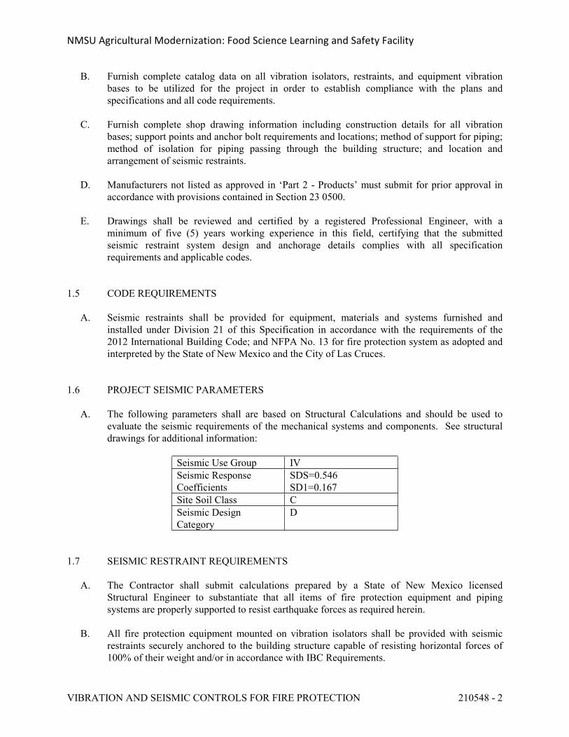
1.6 PROJECT SEISMIC PARAMETERS
A. The following parameters shall are based on Structural Calculations and should be used to evaluate the seismic requirements of the mechanical systems and components. See structural drawings for additional information:
Seismic Use Group IVSeismic Response Coefficients
SDS=0.546SD1=0.167
Site Soil Class CSeismic Design Category
D
1.7 SEISMIC RESTRAINT REQUIREMENTS
A. The Contractor shall submit calculations prepared by a State of New Mexico licensed Structural Engineer to substantiate that all items of fire protection equipment and piping systems are properly supported to resist earthquake forces as required herein.
B. All fire protection equipment mounted on vibration isolators shall be provided with seismic restraints securely anchored to the building structure capable of resisting horizontal forces of 100% of their weight and/or in accordance with IBC Requirements.
NMSU Agricultural Modernization: Food Science Learning and Safety Facility
VIBRATION AND SEISMIC CONTROLS FOR FIRE PROTECTION 210548 - 3
C. All items of fire protection equipment required for life safety including the fire pump and fire protection systems shall be provided with seismic restraints securely anchored to the building capable of resisting horizontal forces of 100% of their weight and/or in accordance with IBC Requirements.
D. All items of fire protection equipment, except as specified above, and all piping furnished and installed under Division 21 shall be provided with seismic restraints securely anchored to the building capable of resisting horizontal forces of 50% of their weight.
E. Seismic restraint/snubber manufacturer shall be responsible for the structural design of attachment hardware as required to attach seismic restraints/snubbers to both the equipment and supporting structure on vibration isolated equipment, or to directly attach equipment to the building structure for non-isolated equipment.
F. The Contractor shall furnish a complete set of approved shop drawings of all mechanical and electrical equipment which is to be restrained to the seismic restraint manufacturer, from which the selection and design of seismic restraint devices and/or attachment hardware will be completed. The shop drawings furnished shall include, at a minimum, basic equipment layout, length and width dimensions, installed operating weights of the equipment to be restrained and the distribution of weight at the restraint points.
PART 2 - PRODUCTS
See Division 23, Section 23 0548, for applicable requirements.
PART 3 - EXECUTION
See Division 23, Section 23 0548, for applicable requirements.
END OF SECTION 210548
NMSU Agricultural Modernization: Food Science Learning and Safety Facility
SUPPRESSION AND ELECTRICAL INSTALLATION COORDINATION 210549 - 1
SECTION 210549 - FIRE SUPPRESSION AND ELECTRICAL INSTALLATION COORDINATION
PART 1 - GENERAL
1.1 REQUIREMENTS
A. Conform with applicable provisions of the General Conditions, Supplemental General Conditions and General Requirements.
1.2 RELATED DIVISIONS AND SECTIONS
A. Section 21 0500, Common Work Results for Fire Suppression.
B. Division 22 for Plumbing Systems.
C. Division 25 for Integrated Automation.
D. Division 26 for Electrical.
E. Division 28 for Fire Alarm System.
1.3 SCOPE
A. It is the intention of this section to summarize the coordination of effort defined in the related sections and divisions of this specification.
B. If there is a conflict between this Section and other Sections and Divisions of this specification, this Section shall be the governing and decisive Section.
C. Make all connections to motors and controls for equipment supplied and/or installed under Division 21 according to Table 1.
PART 2 - PRODUCTS
Not Applicable.
PART 3 - EXECUTION
3.1 INSTALLATION
A. No work shall be performed until the reviewed and marked submittal data have been reissued to the Contractor, unless written permission is obtained from the Architect.
NMSU Agricultural Modernization: Food Science Learning and Safety Facility
SUPPRESSION AND ELECTRICAL INSTALLATION COORDINATION 210549 - 2
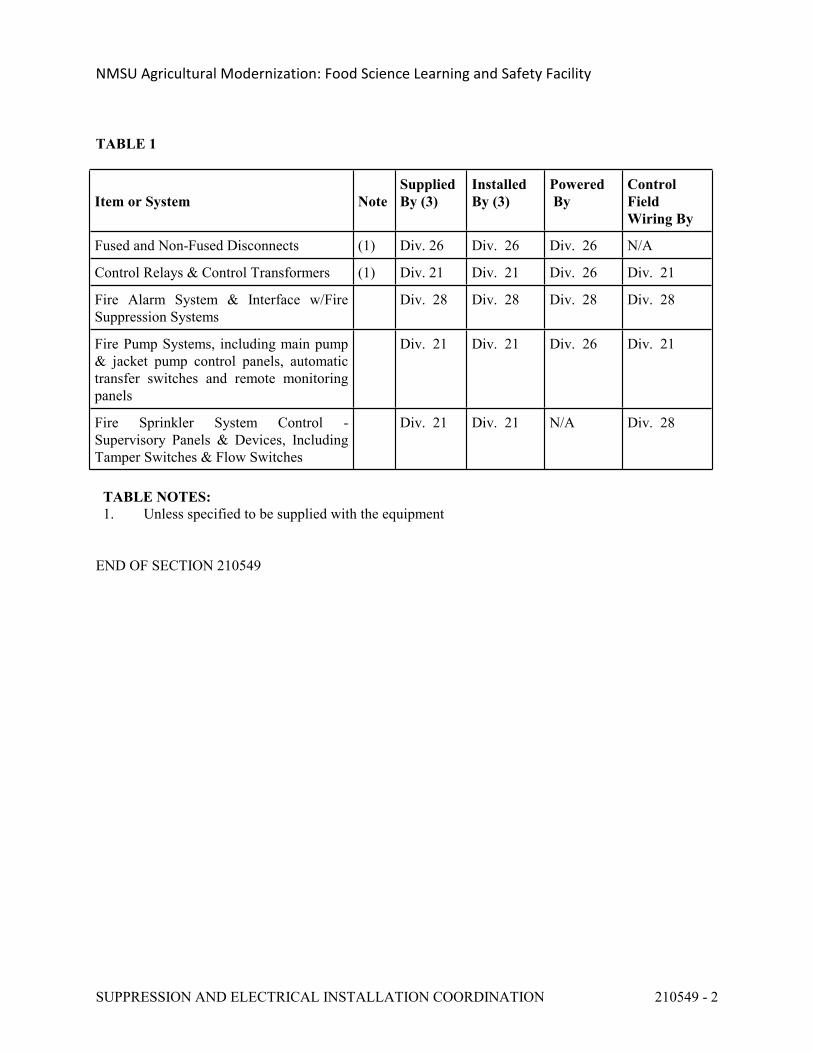
TABLE 1
Item or System NoteSupplied By (3)
Installed By (3)
Powered By
Control Field Wiring By
Fused and Non-Fused Disconnects (1) Div. 26 Div. 26 Div. 26 N/A
Control Relays & Control Transformers (1) Div. 21 Div. 21 Div. 26 Div. 21
Fire Alarm System & Interface w/Fire Suppression Systems
Div. 28 Div. 28 Div. 28 Div. 28
Fire Pump Systems, including main pump & jacket pump control panels, automatic transfer switches and remote monitoring panels
Div. 21 Div. 21 Div. 26 Div. 21
Fire Sprinkler System Control - Supervisory Panels & Devices, Including Tamper Switches & Flow Switches
Div. 21 Div. 21 N/A Div. 28
TABLE NOTES: 1. Unless specified to be supplied with the equipment
END OF SECTION 210549
NMSU Agricultural Modernization: Food Science Learning and Safety Facility
FIRE PROTECTION SYSTEM, AUTOMATIC WET-PIPE SPRINKLER 211313 - 1
SECTION 211313 - FIRE PROTECTION SYSTEM, AUTOMATIC WET-PIPE SPRINKLER
PART 1 - GENERAL
1.1 REQUIREMENTS
A. Conform with applicable provisions of the General Conditions, Supplement General Conditions and the General Requirements.
B. Division 3 for concrete work.
C. Division 26 for electrical work and building fire alarm system.
D. Architectural Sections of this Specification for required cutting, patching, painting, required in conjunction with the installation of the new sprinkler system within the existing facility.
1.2 RELATED SECTIONS
Section 21 0500 Common Work RequirementsSection 21 0503 Trenching and Backfilling for Mechanical SystemsSection 21 0504 Pipe and Pipe FittingsSection 21 0505 Piping SpecialtiesSection 21 0523 ValvesSection 21 1319 Fire Protection System, Automatic Pre-Action SprinklerSection 21 2213 Total Flood Clean Agent Fire Suppression SystemSection 22 6801 Outside UtilitiesSection 23 0549 Fire Suppression and Electrical Installation CoordinationSection 23 3000 Air Tempering System and EquipmentSection 28 3100 Fire Detection and Alarm
1.3 SCOPE
A. Criteria: This Section covers the requirements for furnishing the design, fabrication, installation, and acceptance testing of a complete automatic wet-pipe sprinkler system.
B. Classification: In accordance with NFPA 13 and 101 requirements and recommendations.
C. Scope of Work: Provide the design, materials, equipment, fabrication, installation, labor, and supervision necessary to install, disinfect, flush, test, and place into service a complete wet-pipe sprinkler system.
1. Fully sprinkle the facility per NFPA-13, the International Building Code, International Fire Code, state and/or local Fire Marshal, and any specific requirements of the Owner's insurance underwriter.
D. Components: Provide all piping, fittings, control valves, check valves, alarm valve (with trim), tamper switches, fire department connection, sprinkler heads, hangers, bracing, test and drain
NMSU Agricultural Modernization: Food Science Learning and Safety Facility
FIRE PROTECTION SYSTEM, AUTOMATIC WET-PIPE SPRINKLER 211313 - 2
connections, zone flow switches, tamper switches, accessories and incidentals required for a complete installation in accordance with codes and standards referenced in this Section.
E. Protect all fire lines subject to freezing in a manner approved by NFPA. Use anti-freeze loops only as approved by NFPA and the Local Fire Marshal and only with approved backflow protection in accordance with applicable building codes. Electric heat tape will not be permitted.
F. Conform to the applicable provisions of NFPA Standards 13 and 101 and to the requirements of the International Building Code. Unless otherwise shown on the Drawings or specified, all materials and equipment used in the installation of the fire protection systems shall be listed in the UL Fire Protection Equipment Directory, and shall be the latest design of the manufacturer. All fire hoses, threads and adapters shall match the standards of the City of Las Cruces.
G. Provide temporary fire protection within all areas of the building under construction as required by the building codes and the Fire Marshal.
1.4 QUALITY ASSURANCE
A. All materials and equipment used in the installation of the fire protection systems shall be UL listed and/or FM approved for intended use, unless stated otherwise in these specifications.
B. Contractor Qualifications: Contractor shall be experienced, licensed and regularly engaged in the design, fabrication, and installation of automatic fire protection sprinkler systems.
C. Certification: Welders and brazers shall be qualified per the ASME Boiler and Pressure Vessel Code, Section IX, Qualification Standard for Welding and Brazing Procedures, Welders, Brazers, and Welding and Brazing Operators.
D. Employ skilled craftspersons and provide proper supervision to ensure the work is erected in a proper manner. Coordinate the work with existing conditions and other disciplines. Visit the premises and thoroughly understand the details of the work and working conditions, and verify all dimensions in the field. If discrepancies are noted which require clarification of the design intent, submit RFIs prior to performing related work. Lay out all work in a manner to avoid all interferences.
E. The drawings show only approximate building outlines and interior construction details as an aid in understanding the scope of work. Follow the drawings as closely as building construction and the work of other trades will permit. Investigate the structural and finish conditions affecting the work and arrange the work accordingly, providing such fittings, traps, valves, and accessories as may be required to meet such conditions. Field verify all dimensions and conditions governing the work.
F. Do not render inoperative any building system without prior approval. Coordinate necessary shutdowns through seven day advanced written notification.
G. Coordinate all fire protection piping and sprinklers with the ceiling or roof materials, lighting, ductwork, conduits, piping, suspended equipment, structural, and other building obstructions to provide an installation in compliance with the appropriate building codes, and NFPA Standards.
NMSU Agricultural Modernization: Food Science Learning and Safety Facility
FIRE PROTECTION SYSTEM, AUTOMATIC WET-PIPE SPRINKLER 211313 - 3
1.5 EXISTING CONDITIONS
A. Examine existing conditions and related work required for the design and installation of the fire suppression system.
B. Perform all field tests and inspections as may be necessary to determine water flow, fire protection and pressure characteristics (static and residual pressure and residual flow) necessary for the design and installation of the fire protection system. Contact the water utility to determine whether they anticipate any degradation in the available water source. Prior to starting design, procurement, and installation, submit to the Owner and Engineer a written report documenting the results of this discussion with the water utility.
1.6 INTERRUPTING SERVICES
A. Coordinate the installation of all work in order to minimize interference with the operation of existing building and mechanical, plumbing, fire protection and utility systems during construction. Connections to existing systems requiring the interruption of service within the building shall be carefully coordinated with the Owner to minimize system downtime. Requests for the interruption of existing services shall be submitted in writing a minimum of two (2) weeks before the scheduled date. Absolutely no interruption of the existing services will be permitted without the written approval.
B. All work requiring deactivations of the existing fire protection systems for new connections, relocations, removals, etc, shall be carefully coordinated with the Owner and the Fire Marshal and shall be arranged to minimize system downtime. The Contractor shall provide for all additional costs, as may be required, for work during non-standard hours in order to provide interconnection and interface with the existing fire protection system in order to minimize system deactivation time.
1.7 OPERATION PRIOR TO ACCEPTANCE
A. The Owner may wish to place portions of the fire suppression systems in service prior to substantial completion. In this case, a written agreement will be prepared establishing warranty and other responsibilities to the satisfaction of both parties.
1.8 SUBMITTALS
A. See Division 1 and Section 21 0500 for general submittal requirements.
B. Within 45 days after the contract is awarded, provide submittal data for the complete fire suppression system for review.
1. Submit sprinkler system design drawings and hydraulic calculations to the Fire Marshal, the Building Department AHJ, and the Owner’s Insurer for review, comment, and approval.
NMSU Agricultural Modernization: Food Science Learning and Safety Facility
FIRE PROTECTION SYSTEM, AUTOMATIC WET-PIPE SPRINKLER 211313 - 4
a. Drawings must be prepared by either a minimum Level 3 NICET Certified Technician, or a professional engineer.
b. Drawings must be stamped by a professional engineer registered in fire protection.
2. Upon receipt of stamped and approved system design drawings and hydraulic calculations from the Fire Marshal, the Building Department AHJ, and the Owner’s Insurer, submit required sets of complete submittal data to the Architect as per spec Section 21 0500.
C. Submit complete data describing all equipment and materials to be furnished including performance, quality, dimensions, and certifications of approving agencies. Include plans showing location and arrangement of water supply connection, control valve, fire department connections, alarm bells, tamper switches, on-site fire main routing, on-site fire hydrants and other equipment to be used; and including head layouts coordinated with lighting, plumbing and air conditioning systems. Submittals shall include the following:
1. Shop drawings.2. Certifications (after installation and tests are completed).3. Equipment list.4. Material list.5. Installation instructions.6. Maintenance instructions.7. Operating instructions.8. Samples, colors.9. Welder's certification.10. Catalog data (appropriate unit identified on cut).11. Recommended spare parts lists.12. Verifiable calculations.13. Nameplate data.
D. Complete Package: Submit fire suppression work as a complete package to permit analysis of the system(s) and its components. Partial submittals will not be accepted.
E. Hydraulic Calculations: Submit computerized hydraulic calculations. Maintain a minimum of 10 percent, but not less than a 5 psi buffer below the final water supply curve after accounting for required hose streams, pipe friction elevation differences, etc. Hydraulic design sprinkler system shall be in accordance with the following:
1. Sprinkler System Occupancy Hazard Classifications:
a. Office and Public Areas: Light Hazardb. Storage Areas: Ordinary Hazardc. Equipment Rooms: Ordinary Hazardd. Service Areas: Ordinary Hazard
2. Minimum Density Requirements for Automatic Sprinkler Hydraulic Design:
a. Light Hazard Occupancy: 0.10 gpm over 1500 sf area.b. Ordinary Hazard, Group 1 Occupancy: 0.15 gpm over 1500 sf area.c. Ordinary Hazard, Group 2 Occupancy: 0.20 gpm over 1500 sf area.d. Special Occupancy Hazard: As determined by authority having jurisdiction.
NMSU Agricultural Modernization: Food Science Learning and Safety Facility
FIRE PROTECTION SYSTEM, AUTOMATIC WET-PIPE SPRINKLER 211313 - 5
F. Shop Drawings: Minimum 1/8" = 1'0" for plans, and 1/4" = 1'0" for details, with minimum 3/16 inch lettering. Show all piping, sprinklers, hangers, flexible couplings, roof construction, electro-mechanical devices, and occupancy of each area, including ceiling and roof heights as required by NFPA 13. Show hydraulic reference points and remote areas.
G. Record Drawings: Provide mylar reproducible record drawings and AutoCAD 2008 files showing all work under this contract. Indicate any special systems or devices such as dry pendant heads, antifreeze loops, inspector's test connections, etc. Submit record drawings prior to requesting final payment.
1.9 PRODUCT HANDLING
A. Materials and Equipment: Protect materials and equipment from damage during shipping, storage, and installation.
B. Materials and Equipment Installation: Ensure materials and equipment are free of moisture, scale, corrosion, dirt, and other foreign materials prior to installation.
C. Plugs and Cover Plates: Protect flanged openings with gasketed metal cover plates to prevent damage during shipment. Cap or plug all drains, vents, and small piping or gauge connections.
D. Sprinkler Head Protection: Remove frangible bulb protectors after sprinkler heads are installed. Protect sprinkler heads with factory-supplied caps and covers until ceiling installation is complete.
1.10 ENVIRONMENTAL CONDITIONS
A. The sprinkler system and system components shall be designed to operate at an elevation of 3,900 feet above sea level and in freezing temperatures when exposed to outside conditions.
1.11 ALARM FACILITIES
A. Provide water flow switches and tamper switches. Integrate these and other required sprinkler system alarm devices into the building fire alarm system provided under Division 26. Coordinate with Division 26, Fire Detection and Alarm, regarding the requirements and location of items provided under this section which must be integrated with the fire alarm system.
B. Provide tamper switches on all required valves and devices used in conjunction with the building fire protection system.
1.12 ELECTRICAL CONNECTIONS
A. The fire alarm system will monitor waterflow indicators, tamper switches, etc., provided under this Section.
NMSU Agricultural Modernization: Food Science Learning and Safety Facility
FIRE PROTECTION SYSTEM, AUTOMATIC WET-PIPE SPRINKLER 211313 - 6
PART 2 - PRODUCTS
2.1 GENERAL
A. All material and equipment furnished shall be in accordance with the following requirements and NFPA 13. All fire protection materials and equipment shall be new and unused, shall be free of defects and specifically designed for the use intended, shall conform to the requirements of NFPA 13, and shall be UL listed and FM approved, unless otherwise noted in the Specification.
B. Any deviation to the above requirements shall be submitted to the Architect for approval. The deviation submittal shall be clearly identified as a "deviation."
2.2 PIPING MATERIAL
A. Material Requirement: Automatic sprinkler piping shall be in accordance with this Section and NFPA 13, respectively.
B. Underground piping, to a point 5'0" from the building perimeter, shall be as specified for underground water services in Division 33, Outside Utilities, of this Specification.
C. Underground piping within the building and to a point 5'0" from the building perimeter shall be AWWA Class 200 ductile iron water main pipe and fittings with mechanical joints. Interior of pipe and fittings shall be cement lined. Exterior of pipe and fittings shall be bituminous coating or equivalent. All changes in direction shall be adequately blocked or strapped to prevent separation of joints.
D. Interior building piping systems shall be black steel pipe ASTM A120, or A53 Grade A or B, ERWQ or BW, Standard wall, Schedule 40. UL and FM approved thin wall (Schedule 10, minimum) ASTM A135 or A795 piping may be utilized for sprinkler system as allowed by NFPA and the Fire Marshal. Piping installed outside or exposed to outdoor ambient conditions shall be galvanized.
2.3 FITTINGS
A. Changes of direction shall be accomplished by the use of fittings suitable for use in sprinkler systems as defined in Article 3-13 of NFPA 13. Fittings installed outside or exposed to outdoor ambient conditions shall be galvanized.
B. Fittings and specials for ductile iron pipe shall be Class 250 to match pipe, conforming to AWWA C110, mechanical flange joint type. All ductile iron fittings shall be cement lined.
C. Fittings for steel pipe shall be cast iron screwed, welded fittings, or UL and FM approved mechanical pipe couplings and fittings as manufactured by Victaulic or equivalent in accordance with requirements specified in Section 21 0504.
NMSU Agricultural Modernization: Food Science Learning and Safety Facility
FIRE PROTECTION SYSTEM, AUTOMATIC WET-PIPE SPRINKLER 211313 - 7
2.4 JOINTS
A. Joints shall be provided in accordance with Section 21 0504, Pipe and Pipe Fittings, and the manufacturer's instructions. Threaded joints for thin-wall (Schedule 10) piping shall be provided in strict accordance with NFPA requirements, UL and FM approvals for threadable thin-wall piping.
2.5 UNIONS AND FLANGES
A. Unions and flanges shall be provided in accordance with Section 21 0504, Pipe and Pipe Fittings. Gaskets shall be as recommended by the manufacturer and suitable for service on which used.
2.6 HANGERS AND SUPPORTS
A. See Section 21 0504, Pipe and Pipe Fittings, for general requirements associated with equipment piping systems hangers and supports. Seismic supports for fire protection system shall be provided in accordance with NFPA requirements.
B. All fire protection piping shall be rigidly supported from the building structure by means of adjustable ring type hangers. Piping hangers shall be spaced as specified in NFPA 13, Chapter 2. Piping system shall be installed in an approved manner and shall not overload the structure. The Contractor shall provide additional hangers and steel support members as may be required to distribute the piping weight over several structural members where required or directed. Fire protection piping system shall be supported independent and shall not be attached or supported from hangers, trapezes, or supports provided for other piping systems or equipment.
2.7 VALVES
A. See Section 21 0523, Valves, for general valve requirements. All valves for fire hose fire department connections shall have threads and adapters to match the standard of the City of Las Cruces Fire Department. All valves shall be UL listed and FM approved. Valve sizes shall be determined by the approved hydraulic calculations. Outside screw and yoke valves shall be indicated on the approved hydraulic calculations. Tamper switches shall be provided on all valves controlling fire protection system operation, as required by NFPA. Valves shall be rated for working pressure not less than the maximum pressure to be developed at that point in the system under any operating condition.
B. Gate valves 2" and under, shall be bronze body and trim, outside screw and yoke, wedge disc, screwed connections, 400 psi W.O.G. maximum working pressure.
C. Gate valves, 2-1/2" and larger, shall be Class 125 or Class 250, as required, with flanged ends, outside screw and yoke, bronze seals, wedge disc, iron body.
D. Drain valves shall be globe valve or angle body globe valve, with screwed ends, bronze body and trim, 200 psig W.O.G. maximum working pressure. Furnish and install as required by NFPA No. 13.
NMSU Agricultural Modernization: Food Science Learning and Safety Facility
FIRE PROTECTION SYSTEM, AUTOMATIC WET-PIPE SPRINKLER 211313 - 8
E. Swing check valves 2" and smaller shall be y-pattern, horizontal swing bronze body, bronze trim, 200 psig W.O.G. screwed connections.
F. Swing check valves 2-1/2" and larger, shall be iron body, clearway swing check, Class 125 or Class 250 as required with flanged or grooved connections.
G. Automatic Ball Drips: Automatic ball drips shall be 1/2" or 3/4" as required normally open, which close when the flow of water through the valve exceeds 4 to 10 gpm, 175 psig working pressure, Underwriters' Laboratories, Inc., or Factory Mutual approved, Standard Fire West No. 5248 or equivalent.
H. Post indicator fire main control valve shall be vertical post type for underground valve control or wall type provided as shown on the Drawings, Underwriters' Laboratories, and Factory Mutual approved pattern with approved gate valve and tamper switch. See Section 22 680 for vertical post indicated and underground valves. Vertical post indicator shall be Mueller Co. Model A-20804 with Mueller AWWA non-rising stem gate valve, A-2050 Series or equivalent. Wall type indicator shall be Mueller A-20810 or equivalent.
2.8 ALARM CHECK VALVES
A. Furnish complete wet-pipe sprinkler system alarm check valve assembly with all accessories required for system operation, supervision and alarm. Valves shall be UL listed and FM approved, designed to automatically activate electrically and/or hydraulically operated alarms and shall be furnished in the required size and arrangement with either flanged or grooved connections.
B. Furnish retard chamber, pressure gauges, valves, and trim including water motor gong and alarm switch with both normally open and normally closed electrical contacts.
C. Alarm check valve assembly shall be as manufactured by Tyco Fire Products or equivalent.
2.9 PRESSURE GAUGES
A. Pressure gauges shall be designed for use with water. Gauges shall be of the Bourdon type having an enclosed phosphor-bronze type. The moving parts shall be brass or stainless steel except the hairspring, which is phosphor-bronze. The case and ring shall be brass or stainless steel, and the ring shall be either threaded or pressed over the case. Gauges shall be 4-1/2 inch size with dial marking subdivisions no finer than one percent of the maximum scale reading, and shall be accurate to two percent or less. The gauge scale, when possible, shall be at least twice the maximum working pressure. All gauges shall be FM approved and UL listed.
2.10 TAMPER SWITCHES
All valves which control water to automatic sprinkler heads shall be equipped with supervisory switches having one normally open contact and one normally closed contact. Valve supervisory switches shall be single pole double throw switching contacts, and shall be housed in a gasketed weathertight enclosure. The supervisory device supplied shall be specifically designed to mount on, and operate reliably with, the type of control valve being monitored. All valve
NMSU Agricultural Modernization: Food Science Learning and Safety Facility
FIRE PROTECTION SYSTEM, AUTOMATIC WET-PIPE SPRINKLER 211313 - 9
position switches shall be adjusted to transmit a supervisory signal within two revolutions of the valve operating hand wheel or crank (away from its full open position).
2.11 FLOW SWITCHES
A. Water flow switches shall be field adjustable vane-type with pneumatic retard and 175 psi working pressure. Units shall be single pole double throw, normally open, suitable for 24-volt, DC service or as otherwise required to interface with Building Fire Alarm system. Water flow switches shall be adjusted so that the device will transmit a water flow alarm within 90 seconds of opening the inspector's test valve on the sprinkler system. The flow switch shall be furnished and installed under this Section of Specifications and electrically connected under Division 26. Flow switches when required for zoning shall be piped and installed so that only one flow switch actuates when an alarm in that zone is present.
2.12 SPRINKLER HEADS
A. Sprinkler heads and accessories shall be UL listed or FM approved for the intended service, regular automatic closed type, 165 deg F rated with 1/2" orifice, except as may be otherwise required for the specific application, and subject to NFPA 13 and 101 requirements and recommendations. Sprinkler heads with higher temperature ratings shall be installed in electrical and mechanical equipment areas, in areas where occupancy may generate high ambient temperatures, where installed in the vicinity of heat producing equipment, attic spaces, where exposed to the direct rays of the sun and beneath skylights and windows, and at other such locations as required by NFPA 13. Sprinkler heads throughout the exterior yard #140 and all adjoining spaces shall be 286°F. rated.
B. Sprinkler heads installed in unfinished areas without suspended ceilings shall be upright bronze or brass. Sidewall type heads may be used in areas with low headroom as approved by the Fire Marshal.
C. Sprinkler heads in areas with suspended ceilings including toilet facilities, storage rooms, and similar building spaces shall be chrome plated bronze pendant type or white painted finish as selected by the Architect unless otherwise noted. Sidewall heads in finished areas shall be horizontal, chrome plated bronze.
D. For all building areas, except as indicated above, furnish concealed sprinkler heads consisting of sprinkler head installed within brass enclosure assembly with cover plate with white finish or satin chrome, as approved by the Architect.
E. Supply spare heads of each type as required by NFPA 13. Provide a metal cabinet with a sprinkler head wrench for each type head.
F. Provide sprinkler head guards where required by NFPA 13 and where appropriate.
G. Approved Manufacturers: Tyco Fire Products, Viking, or equivalent.
NMSU Agricultural Modernization: Food Science Learning and Safety Facility
FIRE PROTECTION SYSTEM, AUTOMATIC WET-PIPE SPRINKLER 211313 - 10
2.13 SYSTEM ACCESSORIES
A. Fire Department Connections: Fire department connections shall be of the type and style shown on the civil fire protection drawings, cast brass body, double clappers, plugs, and attached chains. All exposed surfaces, caps and chains shall be chrome plated. Identification shall be by raised letters on the individual devices, or shall consist of attached escutcheon plates of the same material. Label shall read "AUTO SPKR". The dimension from grade level to the center of the 2-1/2-inch inlets shall be 34 inches (plus or minus 2 inches). Make the fire department connection above the inlet to the alarm valve.
B. Plaques: Main riser plaques shall be 7 inches by 10 inches with four mounting holes (one in each corner), and shall have white lettering on red porcelain with white blank for the "design data." Plaque shall meet all requirements of NFPA 13, Chapter 7.
C. Strainers: Strainers, where required, shall be "Y" type with cast iron body, 30 mesh monel screen, flanged ends, 1-1/2-inch blow down connection discharging to outside, and shall be rated at 175 psi working pressure for cold water service.
D. Splash Blocks: Splash blocks shall be concrete, 12 inches by 24 inches by 4 inches thick. A commercially available splash block may be provided as a suitable alternate.
2.14 ACCESS DOORS
A. All concealed valves, controls, etc., shall be provided with access doors as specified under Section 21 0500, Common Work Requirements.
PART 3 - EXECUTION
3.1 FIELD CONDITIONS
A. Prior to installation the Contractor shall carefully inspect the installed work of all other trades and verify that all such work is complete to the point where the installation of the sprinkler system may properly commence.
B. The Contractor shall verify that the entire sprinkler system may be installed in accordance with all referenced codes, regulations, standards, and the original approved design.
3.2 INSTALLATION
A. General
1. The complete fire protection system shall be installed in accordance with NFPA 13. The project drawings provide general information concerning the system arrangements, equipment, material, sizes, and other requirements and shall be utilized by the Contractor for this purpose. However, the Contractor shall have complete responsibility for the system design and installation in accordance with the requirements of this Specification.
2. All pipe, fittings, valves, equipment, and accessories shall be visually examined to ensure that they are clean and free of all burrs, cracks, and other imperfections before being
NMSU Agricultural Modernization: Food Science Learning and Safety Facility
FIRE PROTECTION SYSTEM, AUTOMATIC WET-PIPE SPRINKLER 211313 - 11
installed. During the progress of construction, open ends of pipes, fittings, and valves shall be properly protected at all times to prevent admission of foreign matter.
B. Piping
1. Installation of fire sprinkler piping system shall be in accordance with all applicable requirements contained in Section 21 0500 – Common Work Requirements, Section 21 0504 – Pipe and Pipe Fittings, and Section 21 0505 – Piping Specialties.
2. All fire sprinkler piping shall be so arranged and include such devices to separate the system into individual and distinct alarm zones as shown on the contract drawings and as required by NFPA recommendation and the Fire Marshal. A minimum of one zone per floor will be required unless shown otherwise on the contract drawings.
3. Sprinkler piping shall be marked and identified in accordance with Section 21 0500, Common Work Requirements.
4. The arrangements of all piping systems shall conform to Architectural requirements and field conditions, and shall be run straight and direct, forming right angles or parallel lines with building walls and other pipes, and shall be neatly spaced. Offsets will be provided where required. Standard fittings shall be used for offsets. All risers shall be erected plumb and true, and shall be parallel with the walls and other pipes and shall be neatly spaced. All work shall be coordinated with all Sections of Division 21, 22, and 23, and Division 26, "Electrical," in order to avoid interference of pipe and unnecessary cutting of floors and walls.
5. No pipes or other apparatus shall be installed so as to interfere in any way with the full swing of the building doors, access doors, equipment access, etc.
6. Inspector's test and test pipes shall be piped from the end of the most remote branch line of the automatic sprinkler system to the exterior of the building.
7. When trapped capacity is more than five gallons, provide auxiliary drains consisting of a one-inch valve, nipple, and cap. When trapped capacity is less than five gallons, auxiliary drain shall be one-inch nipple and cap or plug.
8. Provide main drain valves at system alarm valves and extend piping to discharge at exterior at a location approved by the Architect. All pipe and fittings downstream of drain valve shall be galvanized.
9. All concrete penetrations shall be sleeved, then grouted and sealed with fire-resistive material that shall be securely held in place.
C. Welding
1. No field welding of sprinkler piping shall be permitted.2. Headers, risers, feed, crossmains, and branch lines may be shop welded using approved
welding fittings. Welding and brazing shall conform to American National Standard Institute for Power Piping, ANSI B 31.10, with Addenda ANSI B 31.10a and ANSI B 31.10b. Welding and torch cutting shall not be permitted as a means of installing or repairing sprinkler systems.
3. Provide a blind flange at each end of welded headers.4. Welders and brazers shall be certified for welding and/or brazing in accordance with the
requirements of ASME Boiler and Pressure Vessel Code, Section IX, Qualification Standard for Welding and Brazing Procedures, Welders, Brazers, and Welding and Brazing Operators. Welders must be certified for work they perform, and certificates shall be checked before the work commences.
NMSU Agricultural Modernization: Food Science Learning and Safety Facility
FIRE PROTECTION SYSTEM, AUTOMATIC WET-PIPE SPRINKLER 211313 - 12
D. Alarm Check Valve: Alarm check valves shall be installed with the valve and trim set plumb, and shall be unobstructed. Clear distances shall be as listed below:
Rear: 12 inchesSides: 18 inchesFront: 24 inches
E. Control Valves: OS&Y fire protection control valves shall be installed so that the stem can be readily seen.
F. Sprinklers and Accessories
1. Sprinkler heads in finished areas are to be installed on a true axis line in both directions with a maximum deviation from the axis line of 1/2" plus or minus. Heads exceeding this shall be removed and reinstalled. Sprinkler heads shall be located in the center of the ceiling tiles, unless otherwise directed.
2. Provide chrome-plated escutcheons where exposed piping passes through finished floors, walls, partitions, and ceilings. Secure plates to pipe with setscrews or spring clips.
3. Provide spare sprinkler head cabinets per NFPA 13.
3.3 EQUIPMENT INSTALLATION
A. Installation of all devices or equipment not specifically covered by these Specifications shall be in accordance with manufacturer's instructions.
3.4 TEMPORARY FIRE PROTECTION
A. During the construction of the building and until the permanent fire extinguishing system has been installed and is in service, temporary fire protection shall be provided as required by the Fire Marshal.
3.5 INSPECTION AND TESTING
A. The complete fire protection systems and piping acceptance testing shall be performed by the Contractor and witnessed. Advance notice shall be given by the Contractor prior to any tests.
B. Inspection Prior to Testing: The Contractor shall submit notification upon completion of the installation of all materials and equipment.
C. Water Piping Disinfection: The Contractor shall furnish all hoses, connections, and equipment to flush piping clear and free of debris and to rinse piping of disinfectant. Flushing per NFPA Figure A-10.10-2.1. All fittings and connections required for water piping, flushing, and disinfection shall be furnished by the Contractor.
D. Chlorine Application: Water from the existing distribution system, or other approved supply source, shall be made to flow at a constant measured rate into the newly installed piping. The water shall receive a minimum chlorine dosage of 300 mg/1. The Contractor shall not allow any anti-freeze glycerine to come in contact with the chlorine. The chlorine shall be applied
NMSU Agricultural Modernization: Food Science Learning and Safety Facility
FIRE PROTECTION SYSTEM, AUTOMATIC WET-PIPE SPRINKLER 211313 - 13
continuously and for a sufficient period to develop a solid column of chlorinated water that will expose all interior surfaces to a concentration of at least 30 mg/1 for at least three hours. The application shall be checked at a tap near the downstream end of the line by chlorine residual measure. The chlorine residual measurement test shall be performed by the Contractor and the results submitted.
E. Final Flushing: After the applicable retention period, the heavily chlorinated water in the entire system shall be flushed until the chlorine concentration is not higher than that of the source.
F. Pressure Testing: Pressure tests shall consist of at least flushing, hydrostatic testing, and operation testing and shall be performed in strict accordance with the requirements of NFPA 13. For all above-grade piping, test pressure of 200 psi shall be held for a continuous period of two hours with no drop in pressure. Each complete system (main riser with all associated piping and alarms) shall be tested and accepted as a complete unit. System pressure test shall be against a blank test flange and not against a valve seat. Tests may be conducted by the Contractor on small sections of each complete unit for the benefit of the Contractor. An air pressure test may be provided in accordance with NFPA 13. An air pressure of 40 psig shall be pumped up, allowed to stand 24 hours, and all leaks which allow a loss of pressure over 1.5 psig during the 24 hours shall be fixed.
G. Unsatisfactory Tests: If any of the above tests fail to produce satisfactory results, tests shall be repeated at no additional cost to the Owner until satisfactory results have been obtained.
3.6 CERTIFICATION
A. The Contractor shall certify that the system has been installed in accordance with all referenced codes and standards. The Contractor shall submit this certification upon completion of tests.
3.7 MAINTENANCE AND OPERATING INSTRUCTIONS
A. System description, system theory of operation, and system final inspection and acceptance documents of the completed system shall be submitted in a bound book (four copies). The maintenance manuals and instructions shall include a brief description of the type of system installed, routine-type work defined by step-by-step instructions that should be performed to ensure long life and proper operations, and the recommended frequency of performance. The instructions shall also include possible trouble spots with diagnosis and suggested correction of each. The theory of operation brochures shall describe the function of each component or subassembly. A copy of the completed Contractor's Materials and Test Certificate (reference NFPA-13, Chapter 24) shall be included to document the final inspection, operating test, acceptance and placement of system in service.
END OF SECTION 211313
NMSU Agricultural Modernization: Food Science Learning and Safety Facility
AUTOMATIC PRE-ACTION SPRINKLER 211319 - 1
SECTION 211319 - AUTOMATIC PRE-ACTION SPRINKLER
PART 1 - GENERAL
1.1 REQUIREMENTS
A. Conform with applicable provisions of the General Conditions, Supplemental General Conditions and the General Requirements.
B. See Division 3 for concrete work.
C. See Division 26 for electrical work.
D. See Division 28 for building fire alarm system.
E. See Division 25, Integrated Automation.
F. See Architectural Sections of this Specification for required cutting, patching, painting, etc. required in conjunction with the installation of the new sprinkler system within the existing facility.
1.2 RELATED SECTIONS
A. Section 21 0500, Common Work Requirements for Fire Suppression.
B. Section 21 0503, Trenching and Backfilling for Fire Suppression.
C. Section 21 0504, Pipe and Pipe Fittings for Fire Suppression.
D. Section 21 0505, Piping Specialties for Fire Suppression.
E. Section 21 0523, Valves.
F. Division 22 for plumbing systems.
G. Division 23 for HVAC systems.
1.3 SCOPE
A. Criteria: This section covers the requirements for furnishing design, fabrication, installation, and acceptance testing of a complete automatic pre-action sprinkler system.
B. Classification: In accordance with NFPA Standard No. 13 and 101 requirements and recommendations.
C. Scope of Work: The work to be performed shall include furnishing the design, materials,
NMSU Agricultural Modernization: Food Science Learning and Safety Facility
AUTOMATIC PRE-ACTION SPRINKLER 211319 - 2
equipment, fabrication, installation, labor, transportation, and supervision necessary to install, disinfect, flush, test, and place into service a complete pre-action sprinkler system to serve the areas indicated on the drawings and described herein.
1. Fire protection system shall be provided to fully sprinkle the complete facility in accordance with NFPA Standards, International Building Code and Uniform Fire Code requirements, the state and/or local Fire Marshal, and any specific requirements of the Owner's insurance underwriter.
D. Components: The system shall consist of interconnecting piping, fittings, control valves, check valves, alarm valve (with trim), tamper switches, fire department connection, sprinkler heads, hangers, bracing, test and drain connections, zone flow switches, accessories and incidentals required for other devices for a complete installation in accordance with codes and standards referenced in this section.
E. All fire lines subject to freezing shall be protected in a manner approved by NFPA and accepted. Electric heat tape will not be permitted.
F. The fire protection systems shall conform to the applicable provisions of NFPA Standard No. 13 and 101 and to the requirements of the International Building Code. Unless otherwise shown on the drawings or specified, all materials and equipment used in the installation of the fire protection systems shall be listed as approved by the Underwriters' Laboratories List of Approved Equipment, Fire Protection Devices and Devices Involving Fire Hazard, and shall be the latest design of the manufacturer. All fire hoses, threads and adapters shall match the standards of the City of Las Cruces.
G. Temporary fire protection within all areas of the building under construction as required by the building codes and the Fire Marshal.
H. Coordination with work to be provided under other Divisions of this Specification for required cutting, patching, repair, and replacement of building wall, floors, ceiling, etc. required for the installation of the new fire protection system within the existing facility.
1.4 QUALITY ASSURANCE
A. All materials and equipment used in the installation of the fire protection systems shall be listed as approved by the Underwriters' Laboratory and/or by Factory Mutual for intended use, unless stated otherwise in these specifications.
B. Contractor Qualifications: The systems shall be furnished and installed by an experienced firm duly licensed and regularly engaged in the design, fabrication, and installation of automatic sprinkler systems for fire protection.
C. Certification: Welders and braziers shall be certified for welding and/or brazing in accordance with the requirements of the ASME Boil and Pressure Vessel Code, Section IX, Qualification Standard for Welding and Brazing Procedures, Welders, Braziers, and Welding and Brazing Operators.
D. The installation shall be accomplished by the skilled craftspeople of the trades involved in the
NMSU Agricultural Modernization: Food Science Learning and Safety Facility
AUTOMATIC PRE-ACTION SPRINKLER 211319 - 3
work in a thorough, workmanlike manner. The Contractor shall be specifically responsible for the coordination and proper relation of his work to building structures and other work provided under other Sections of this specification. The Contractor shall visit the premises and thoroughly familiarize himself with details of the work and working conditions and verify all dimensions in the field. If discrepancies are noted, the Contractor shall advise in writing of such discrepancies prior to the performance of any work. The Contractor shall lay out all work in a manner to avoid all interferences.
E. The Drawings show only approximately building outlines and interior construction details as an aid in understanding the scope of work. The Drawings shall be followed as closely as actual building construction and work of other trades will permit. The Contractor shall investigate the structural and finish conditions affecting the work and shall arrange his work accordingly, providing such fittings, traps, valves, and accessories as may be required to meet such conditions. The Contractor shall field verify all dimensions and conditions governing the work required.
F. The Contractor shall not render inoperative any building system without prior approval. The Contractor shall coordinate necessary shutdowns of existing systems by written notification a minimum of seven working days before rendering such system inoperative.
G. The Contractor shall ensure that all sprinkler piping, sprinkler heads and associated equipment are installed and coordinated with ceiling or roof materials, lighting, ductwork, conduit, piping, suspended equipment, structural, and other building obstructions to provide a complete installation in complete compliance with the appropriate building codes, and NFPA Standards.
1.5 EXISTING CONDITIONS
A. The Contractor shall examine existing conditions and related work required for the design and installation of the fire protection system required under this section of the Specifications.
B. The Contractor shall perform all field tests and inspections as may be necessary to determine water flow, fire protection and pressure characteristics (static and residual pressure and residual flow) necessary for the design and installation of the fire protection system. The Contractor shall verify with the municipal water department/utility that water flow test data taken will be representative for conditions throughout the years, and is appropriate for fire protection system design and operation. The Contractor shall provide a written report describing any conditions to which would prevent proper provisions of this work. Beginning work of the Section without reporting unsuitable conditions constitutes acceptance of conditions by the Contractor. The Contractor shall be required to perform any necessary removal, repair, or replacement of work caused by unsuitable conditions which are unreported as described herein, at no additional cost to the Owner.
1.6 INTERRUPTING SERVICES
A. The Contractor shall coordinate the installation of all work in order to minimize interference with the operation of existing building and mechanical, plumbing, fire protection and utility systems during construction. Connections to existing systems requiring the interruption of service within the building shall be carefully coordinated with the Owner to minimize system
NMSU Agricultural Modernization: Food Science Learning and Safety Facility
AUTOMATIC PRE-ACTION SPRINKLER 211319 - 4
downtimes. Requests for the interruption of existing services shall be submitted in writing a minimum of two (2) weeks before the scheduled date. Absolutely no interruption of the existing services will be permitted without written approval.
B. All work requiring deactivations of the existing fire protection systems for new connections, relocations, removals, etc. shall be carefully coordinated with the Owner and the Fire Marshal and shall be arranged to minimize system downtime. Contractor shall provide for all additional costs, as may be required, for work during non-standard hours in order to provide interconnection and interface with the existing fire protection system in order to minimize system deactivation time.
1.7 OPERATION PRIOR TO ACCEPTANCE
A. Operation of equipment and systems installed by the Contractor for the benefit of the Owner prior to full project substantial completion may be required, in which case a written agreement between the Owner and the Contractor establishing warranty and other responsibilities to the satisfaction of both parties shall be provided. This shall include activation of the fire protection systems within building zones and areas, as directed by the Owner and the Fire Marshal.
1.8 SUBMITTALS
A. See Division 1 and Section 21 0500 for general submittal requirements.
B. Within forty-five (45) days after the contract is awarded, the Contractor shall provide submittal data for the complete fire protection system for review. No construction work shall begin or equipment purchased without written approval.
1. Submit sprinkler system design drawings and hydraulic calculations to the Fire Marshal and Building Department "authority having jurisdiction" for review, comment, and approval.
a. Drawings shall be prepared by either a minimum Level 3NICET Certified Technician, or a professional engineer.
b. Drawings shall be stamped by a professional engineer registered in fire protection.
2. Complete submittals shall be transmitted to the Owner's Insurance Agent in the number of copies required by the Agent. Submittals that have been approved by the Insurance Agent shall then be submitted with written proof of approval by the above.
3. Upon receipt of stamped and approved system design drawings and hydraulic calculations from the Fire Marshal, the Contractor shall submit required sets of complete submittal data as described herein.
C. Submittals shall include complete data describing all equipment and materials to be furnished including performance, quality, dimensions, and certifications of approving agencies. Complete drawings of the system shall be submitted including plot plan showing location and arrangement of water supply connection, control valve, fire department connections, alarm bells, tamper switches, on-site fire main routing, on-site fire hydrants and other equipment to be used; and including head layouts coordinated with lighting, plumbing and air conditioning
NMSU Agricultural Modernization: Food Science Learning and Safety Facility
AUTOMATIC PRE-ACTION SPRINKLER 211319 - 5
systems. Submittals shall include the following:
1. Shop drawings.2. Certifications (after installation and tests are completed).3. Equipment list.4. Material list.5. Installation instructions.6. Maintenance instructions.7. Operating instructions.8. Samples, colors.9. Welder's certification.10. Catalog data (appropriate unit identified on cut).11. Recommended spare parts list.12. Verifiable calculations.13. Nameplate data.
D. Complete Package: Required submittals shall be submitted as a complete package to permit analysis of the system(s) and its components. A partial submittal shall not be accepted. No work shall proceed until the submittals are approved.
E. Hydraulic Calculations: The Contractor shall submit complete hydraulic calculations with the shop drawings. The calculations shall include a completed set of hydraulic calculations or equivalent computer printout and shall be performed in accordance with the requirements of NFPA 14. The Contractor shall calculate the demand point for each system so that it remains a minimum of 5 PSI below the final water supply curve after required hose streams and friction loss to the base of the riser have been deducted. The contractor shall include in the calculations elevation differences between the point of the water test and the base of the riser. Hydraulic design sprinkler system shall be in accordance with the following:
1. Sprinkler System Occupancy Hazard Classifications:
a. Office & Public Areas: Light Hazardb. Storage Areas: Ordinary Hazardc. Equipment Rooms: Ordinary Hazardd. Service Areas: Ordinary Hazard
2. Minimum Density Requirements for Automatic Sprinkler Hydraulic Design:
a. Light Hazard Occupancy: 0.10 GPM over 1500 SF area.b. Ordinary Hazard, Group 1 Occupancy: 0.15 GPM over 1500 SF area.c. Ordinary Hazard, Group 2 Occupancy: 0.20 GPM over 1500 SF area.d. Special Occupancy Hazard: As determined by authority having
jurisdiction.
F. Shop Drawing: Shop drawings shall be prepared using a minimum scale of 1/8" = 1'0" for plans, and 1/4" = 1'0" for details. All hand lettering shall be a minimum of 3/16 inch and all other lettering a minimum of 1/8 inch to permit microfilm reductions. Show all piping, sprinklers, hangers, flexible couplings, roof construction, all electro-mechanical devices, and occupancy of each area, including ceiling and roof heights as required by NFPA 13, Chapters 1
NMSU Agricultural Modernization: Food Science Learning and Safety Facility
AUTOMATIC PRE-ACTION SPRINKLER 211319 - 6
- 9. Hydraulic reference points and remote areas shall be shown.
G. Record Drawings: The Contractor shall provide Mylar reproducible record drawings showing all work as completed under this contract. Layout shall include notes on all special systems or devices such as dry pendant heads, antifreeze loops, inspector's test connections, etc. Drawings will be required at completion of work before job will be considered complete.
1.9 PRODUCT HANDLING
A. Materials and Equipment: All materials and equipment shall be protected from damage during shipping, storage, and installation.
B. Materials and Equipment Installation: Prior to installation, materials and equipment shall be free of moisture, scale, corrosion, dirt, and other foreign materials.
C. Plugs and Cover Plates: All flanged openings shall be protected with gasketed metal cover plates to prevent damage. All drains, vents, and small piping or gauge connections shall be capped or plugged.
1.10 ENVIRONMENTAL CONDITIONS
A. The sprinkler system and system components shall be designed to operate at an altitude of 3,900 feet above sea level and freezing temperatures when exposed to outside conditions.
1.11 ALARM FACILITIES
A. Equipment necessary to accomplish the required waterflow alarm shall be furnished and installed under this section of the specifications. Waterflow detection devices shall consist of approved waterflow indicators as specified herein.
B. Local alarm shall consist of an approved electrical audible alarm furnished by and wired under Division 28, Fire Alarm System.
C. Waterflow indicators, tamper switches, and other required sprinkler system alarm functions shall be integrated into the building fire alarm system under Division 28. Contractor shall coordinate with Division 28, Fire Alarm Systems., in order to requirements and location of items provided under this section which require connection to the fire alarm furnished.
D. Contractor shall provide tamper switches on all required valves and devices, used in conjunction with the building fire protection system.
1.12 ELECTRICAL CONNECTIONS
A. Electrical connections from devices and components including waterflow indicators, tamper switches, etc., furnished and installed under this section shall be connected to the building electrical system under Division 26 and building fire alarm systems under Division 28.
NMSU Agricultural Modernization: Food Science Learning and Safety Facility
AUTOMATIC PRE-ACTION SPRINKLER 211319 - 7
PART 2 - PRODUCTS
2.1 GENERAL
A. All material and equipment furnished shall be in accordance with the following requirements and NFPA 13. All fire protection materials and equipment shall be new and unused, shall be free of defects and specifically designed for the use intended, shall conform to the requirements of NFPA 13, and shall be UL listed and FM approved, unless otherwise noted in the specifications.
B. Any deviation to the above requirements shall be submitted to the Architect for approval. The deviation submittal shall be clearly identified as "deviation."
2.2 PIPING MATERIAL
A. Material Requirement: Automatic sprinkler piping shall be in accordance with this section and NFPA 13, respectively.
B. Underground piping, to a point 5'0" from the building perimeter, shall be as specified for underground water services in Division 33 of this specification.
C. Underground piping within the building and to a point 5'0" from the building perimeter shall be AWWA Class 200 ductile iron water main pipe and fittings with mechanical joints. Interior of pipe and fittings shall be cement lined. Exterior of pipe shall be bituminous coating or equivalent. All changes in direction shall be adequately blocked or strapped to prevent separation of joints.
D. Interior building piping systems shall be black steel pipe ASTM A120, or A53 grade A or B, ERWQ or BW, Standard wall, Schedule 40. UL and FM approved thin wall (Schedule 10, minimum) ASTM A135 or A795 piping may be utilized for sprinkler system as allowed by NFPA and the Fire Marshal. Piping installed outside or exposed to outdoor ambient conditions shall be galvanized.
2.3 FITTINGS
A. Changes of direction shall be accomplished by the use of fittings suitable for use in sprinkler systems as defined in Article 3-13 of NFPA 13. Fittings installed outside or exposed to outdoor ambient conditions shall be galvanized.
B. Fittings and specials for ductile iron pipe shall be Class 250 to match pipe, conforming to AWWA C110, mechanical flange joint type. All ductile iron fittings shall be cement lined.
NMSU Agricultural Modernization: Food Science Learning and Safety Facility
AUTOMATIC PRE-ACTION SPRINKLER 211319 - 8
C. Fittings for steel pipe shall be cast iron screwed, welded fittings, or UL and FM approved mechanical pipe couplings and fittings as manufactured by Victaulic or equivalent in accordance with requirements specified in Section 21 0504.
2.4 JOINTS
A. Joints shall be provided in accordance with Section 21 0504 and the manufacturer's instructions
2.5 UNIONS AND FLANGES
A. Unions and flanges shall be provided in accordance with Section 21 0504. Gaskets shall be as recommended by the manufacturer and suitable for service on which used.
2.6 HANGERS AND SUPPORTS
A. See Section 21 0504 for general requirements associated with equipment and piping systems hangers and supports. Seismic supports for fire protection system shall be provided in accordance with NFPA requirements and Section 21 0548.
B. All fire protection piping shall be rigidly supported from the building structure by means of adjustable ring type hangers. Piping hangers shall be spaced as specified in NFPA 13, Chapter 3. Piping system shall be installed in an approved manner and overload the structure. Contractor shall provide additional hangers and steel support members as may be required to distribute the piping weight over several structural members where required or directed. Fire protection piping system shall be supported independent and shall not be attached or supported from hangers, trapezes, or supports provided for other piping systems or equipment.
2.7 VALVES
A. See Section 21 0523 for general valve requirements. All valves for fire hose fire department connections shall have threads and adapters to match the standard of the City of Las Cruces Fire Department. All valves shall be UL listed and FM approved. Valve sizes shall be determined by the approved hydraulic calculations. Outside screw and yoke valves shall be indicated on the approved hydraulic calculations. Tamper switches shall be provided on all valves controlling fire protection system required by NFPA. Valves shall be rated for working pressure not less than the maximum pressure to be at that point in the system under any operating condition.
B. Gate valves, 2" and under, shall be bronze body and trim, outside screw and yoke, wedge disc, screwed connections, 400 PSI W.O.G. Maximum working pressure.
C. Gate valves, 2-1/2" and larger, shall be Class 125 or Class 250, as required, with flanged ends, outside screw and yoke, bronze seals, wedge disc, iron body.
D. Drain valves shall be globe valve or angle body globe valve, with screwed ends, bronze body and trim, 200 PSIG W.O.G. maximum working pressure. Furnish and install as required by
NMSU Agricultural Modernization: Food Science Learning and Safety Facility
AUTOMATIC PRE-ACTION SPRINKLER 211319 - 9
NFPA No. 13.
E. Swing check valves, 2" and smaller shall be y-pattern, horizontal swing bronze body, bronze trim, 200 PSIG W.O.G. screwed connections.
F. Swing check valves, 2-1/2" and larger, shall be Class 125 or Class 250 as required with iron body, clearway swing check, flange connections.
G. Automatic Ball Drips: Automatic ball drips shall be 1/2" or 3/4" as required normally open, which close when the flow of water through the valve exceeds 4 to 10 GPM, 175 PSIG working pressure, Underwriters' Laboratories, Inc., or Factory Mutual approved, Standard Fire West No. 5248 or equivalent.
H. Post indicator fire main control valve shall be vertical post type for underground valve control wall type provided as shown on the drawings, Underwriters' Laboratories, and Factory Mutual approved pattern with approved gate valve and tamper switch. See Division 22, Division 2 for vertical post indicated and underground valves. Vertical post indicator shall be Mueller Co. Model A-20804 with Mueller AWWA non-rising stem gate valve, A-2050 Series or equivalent. Wall type indicator shall be Mueller A-20810 or equivalent.
2.8 PRE-ACTION SYSTEM ALARM VALVE
A. Furnish complete pre-action sprinkler system alarm valve assembly with all accessories required for system pneumatic supervision and electric activator from fire detection system, including the following components:
1. System control deluge valve, GEM model A-4 Multimatic, or equivalent, 175 PSIG rating, horizontal or vertical arrangement, as required, electric activator, UL listed and FM approved. Furnish with all required trim including solenoid valve with electric activation trim, pressure alarm switch, pressure gauges, drain and control valves and fittings.
2. Swing Check Valve, GEM Model F520 or F5201, or equivalent, horizontal or vertical arrangement as required, 175 PSIG rating, for use with pre-action system having 1.5 PSIG supervisory pressure, flanged or flanged by grooved inlet and outlet connections.
3. Supervisory Control System, GEM model F112 or equivalent pneumatic (1.5 PSIG) air supervising system including air pump and motor, check valve, filter-dryer assembly, pressure switch and controls, all internally wired and piped in a NEMA Type 1 metal panel. Provide 1.5 PSIG low pressure alarm switch for inter-connection to building fire alarm system.
4. Water motor alarm, GEM model F630, or equivalent, hydraulically operated outdoor alarm.
B. Sprinkler system pre-action valve shall be sized as indicated on the approved shop drawings. A bypass valve shall be included in the trim which will allow test operation of the pressure alarm switch without tripping the pre-action valve clapper. In all cases where the retard chamber drain line ties into the main riser drain, the retard chamber drain line shall have a check valve installed to drain.
C. Pre-action sprinkler system electric control devices shall be 115 VAC. A complete building
NMSU Agricultural Modernization: Food Science Learning and Safety Facility
AUTOMATIC PRE-ACTION SPRINKLER 211319 - 10
fire alarm system shall be provided under Division 16 of this specification. Actuation of the fire detection system shall cause that system to send an electrical signal to open the pre-action alarm valve, permitting water to flow into the sprinkler piping. If any sprinkler heads have been opened by a fire, water can then be discharged from the open sprinkler heads. Loss of supervisory pressure from the piping system as a result of damaged sprinklers or broken piping shall provide a trouble signal through the pre-action system supervisory pressure control system and low pressure switch, to the Building Fire Alarm System to indicate impairment of the fire protection system. Deluge valve shall not open due to a loss of supervisory pressure.
2.9 PRESSURE GAUGES
A. Pressure gauges shall be designed for use with water. Gauges shall be of the Bourdon type having an enclosed phosphor-bronze type. The moving parts shall be brass or stainless steel except the hair spring, which is phosphor-bronze. The case and ring shall be brass or stainless steel, and the ring shall be either threaded or pressed over the case. Gauges shall be 4-1/2 inch size with dial marking subdivisions no finer than one percent of the maximum scale reading, and shall be accurate to two percent or less. The gauge scale, when possible, shall be at least twice the maximum working pressure. All gauges shall be FM approved and UL listed.
2.10 TAMPER SWITCHES
A. All valves which control water to automatic sprinkler heads shall be equipped with supervisory switches having one normally open contact and one normally closed contact. Valve supervisory switches shall be single pole double throw switching contacts, and shall be housed in a gasketed weathertight enclosure. The supervisory device supplied shall be specifically designed to mount on, and operate reliably with, the type of control valve being monitored. All valve position switches shall be adjusted to transmit a supervisory signal within two revolutions of the valve operating hand wheel or crank (away from its full open position).
2.11 FLOW SWITCHES
A. Water flow switches shall be field adjustable vane-type with pneumatic retard and 175 PSI working pressure. Units shall be single pole double throw, normally open, suitable for 24-volt, DC service or as otherwise required to interface with Building Fire Alarm system. Water flow switches shall be adjusted so that the device will transmit a water flow alarm within 90 seconds of opening the inspector's test valve on the sprinkler system. The flow switch shall be furnished and installed under this section of specifications and electrically connected under Division 16. Flow switches when required for zoning shall be piped and installed so that only one flow switch actuates when an alarm in that zone is present.
2.12 SPRINKLER HEADS
A. All sprinkler heads and accessories shall be UL listed and FM approved for the intended service, regular automatic closed type, 165oF rated with 1/2" orifice, except as may be otherwise required for the specific application, and subject to NFPA No. 13 and No. 101 requirements and recommendations. Sprinkler heads with higher temperature ratings shall be
NMSU Agricultural Modernization: Food Science Learning and Safety Facility
AUTOMATIC PRE-ACTION SPRINKLER 211319 - 11
installed in electrical and mechanical equipment areas, in areas where occupancy may generate high ambient temperatures, where installed in the vicinity of heat producing equipment, attic spaces, where exposed to the direct rays of the sun and beneath skylights and windows, and at other such locations as required by NFPA No. 13 and No. 101.
B. New fire sprinkler pendent heads shall be chrome plated recessed quick response type, except as otherwise specified herein and required by Code.
C. Sprinkler heads installed in unfinished areas without suspended ceilings shall be upright bronze or brass. Sidewall type heads may be used in areas with low head room as approved by the Fire Marshal.
D. Sprinkler heads in areas with suspended ceilings including toilet facilities, storage rooms and similar building spaces shall be chrome plated bronze pendant type unless otherwise noted. Sidewall heads in finished areas shall be horizontal, chrome plated bronze.
E. For all building areas, except as indicated above, furnish concealed sprinkler heads consisting of sprinkler head installed within brass enclosure assembly with cover plate with white painted finish or satin chrome, as selected by the Architect.
F. Contractor shall furnish spare heads of each type as required by NFPA No. 13, installed in a metal cabinet with a sprinkler head wrench for each type head.
G. Furnish and install sprinkler head guards where required to protect head from damage as required by NFPA.
H. Sprinkler heads shall be furnished by GEM, Grinnell, Viking, or equivalent.
2.13 FIRE EXTINGUISHER CABINETS
A. Fire extinguishers mounted in suitable cabinets shall be provided in locations indicated on the Architectural Drawings and as NFPA and International Building Code provisions.
B. Extinguishers and cabinets shall be as furnished and installed under the Architectural Sections of the Specifications.
2.14 SYSTEM ACCESSORIES
A. Fire department connections shall be of the type and style shown on the drawings cast brass body, plugs, and attached chains. All exposed surfaces, caps and chains shall be chrome plated. Identification shall be by raised letters on the individual devices, or shall consist of attached escutcheon plates of the material. Label shall read "AUTO SPKR". The dimension from grade level to the center of the 2-1/2-inch inlets shall be 34 inches minus 2 inches). Make the fire department connection below the inlet to the alarm valve.
B. Main riser plaques shall be 7 inches by 10 inches with four mounting holes (one in each
NMSU Agricultural Modernization: Food Science Learning and Safety Facility
AUTOMATIC PRE-ACTION SPRINKLER 211319 - 12
corner), and shall have white lettering on red porcelain with white blank for the "design data." Plaque shall meet all requirements of NFPA 13, Chapter 7.
C. Strainers, where required, shall be "Y" type with cast iron body, 30 mesh monel screen, flanged ends, 1-1/2-inch blow-down connection discharging to outside, and shall be rated at 175 PSI working pressure for cold water service.
D. Splash blocks shall be concrete, 12 inches by 24 inches by 4 inches thick. A commercially-available splash block may be provided as a suitable alternate.
2.15 ACCESS DOORS
A. All concealed valves, controls, etc., shall be provided with access doors as specified under Section 21 0500.
PART 3 - EXECUTION
3.1 FIELD CONDITIONS
A. Prior to installation the Contractor shall carefully inspect the installed work of all other trades and verify that all such work is complete to the point where the installation of the sprinkler system may properly commence.
B. The Contractor shall verify that the entire sprinkler system may be in accordance with all referenced codes, regulations, standards, and the original approved design.
3.2 INSTALLATION
A. General:
1. The complete fire protection system shall be installed in accordance with NFPA 13. The project drawings provide general information concerning the system arrangements, equipment, material, sizes, and other requirements and shall be utilized by the Contractor for this purpose. However, the Contractor shall have complete responsibility for the system design and installation in accordance with the requirements of this Specification.
2. All pipe, fittings, valves, equipment, and accessories shall be visually examined to ensure that they are clean and free of all burrs, cracks, and other imperfections before being installed. During the progress of construction, open ends of pipes, fittings, and valves shall be properly protected at all times to prevent admission of foreign matter.
B. Piping:
1. Installation of fire sprinkler piping system shall be in accordance with all applicable
NMSU Agricultural Modernization: Food Science Learning and Safety Facility
AUTOMATIC PRE-ACTION SPRINKLER 211319 - 13
requirements contained in Sections 21 0500, 21 0504, and 21 0505.2. All fire sprinkler piping shall be so arranged and include such devices to separate the
system into individual and distinct alarm zones as shown on the contract drawings and as required by NFPA recommendation and the Fire Marshal. A minimum of one zone per floor will be required unless shown otherwise on the contract drawings.
3. Sprinkler piping shall be marked and identified in accordance with Section 21 0500.4. The arrangements of all piping systems shall conform to Architectural requirements and
field conditions, and shall be run straight and direct, forming right angles or parallel lines with building walls and other pipes, and shall be neatly spaced. Offsets will be provided where required. Standard fittings shall be used for offsets. All risers shall be erected plumb and true, and shall be parallel with the walls and other pipes and shall be neatly spaced. All work shall be coordinated with all Division 22, Plumbing, Division 23, HVAC and Division 26, Electrical, in order to avoid interference of pipe and unnecessary cutting of floors and walls.
5. No pipes or other apparatus shall be installed so as to interfere in any way with the full swing of the building doors, access doors, equipment access, etc.
6. Inspector's test pipes shall be piped from the end of the most remote branch line of the automatic sprinkler system to the exterior of the building.
7. When trapped capacity is more than five gallons, provide auxiliary drains consisting of a one-inch valve, nipple, and cap. When trapped capacity is less than five gallons, auxiliary drain shall be one-inch nipple and cap or plug.
8. Provide main drain valves at system alarm valves and extend piping to building floor sink in an approved manner. All piping and fittings downstream of drain valve shall be galvanized.
9. All concrete penetrations shall be sleeved, then grouted and sealed with fire-resistive material that shall be securely held in place.
C. Welding:
1. No field welding of sprinkler piping shall be permitted. 2. Headers, risers, feed, cross mains, and branch lines may be shop welded using approved
welding fittings. Welding and brazing shall conform to American National Standard Institute for Power Piping, ANSI B 31.10, with Addenda ANSI B 31.10a and ANSI B 31.10b. Welding and torch cutting shall not be permitted as a means of installing or repairing sprinkler systems.
3. Provide a blind flange at each end of welded headers. 4. Welders and braziers shall be certified for welding and/or brazing in accordance with the
requirements of ASME Boiler and Pressure Vessel Code, Section IX, Qualification Standard for Welding and Brazing Procedures, Welders, Braziers, and Welding and Brazing Operators. Welders must be certified for work they perform, and certificates shall be checked before the work commences.
D. Pre-Action Check Valve: Pre-Action check valves shall be installed with the valve and trim set plumb, and shall be unobstructed. Clear distances shall be as listed below:
1. Rear: 12 inches2. Sides: 18 inches 3. Front: 24 inches
E. Control Valves: OS & Y fire protection control valves shall be installed so that the stem can be
NMSU Agricultural Modernization: Food Science Learning and Safety Facility
AUTOMATIC PRE-ACTION SPRINKLER 211319 - 14
readily seen.
F. Sprinklers and Accessories:
1. Sprinkler heads in finished areas are to be installed on a true axis line in both directions with a maximum deviation from the axis line of 1/2" plus or minus. Heads exceeding this shall be removed and reinstalled. Sprinkler heads shall be located in the center of the ceiling tiles, unless otherwise directed.
2. Provide chrome-plated escutcheons where exposed piping passes through finished floors, walls, partitions, and ceilings. Secure plates to pipe with set screws or spring clips.
3. Provide one spare sprinkler cabinet, complete with sprinklers of assorted temperature ratings of the type necessary and in use throughout the installation, at each main riser valve. Each cabinet shall be equipped per NFPA 13, 3-16.7.
3.3 EQUIPMENT INSTALLATION
A. Installation of all devices or equipment not specifically covered by these specifications shall be in accordance with manufacturer's instructions.
3.4 TEMPORARY FIRE PROTECTION
A. During the construction of the building and until the permanent fire extinguishing system has been installed and is in service, temporary fire protection shall be provided as required by the Fire Marshal.
3.5 INSPECTION AND TESTING
A. The complete fire protection systems and piping acceptance testing shall be performed by the Contractor and witnessed. Advance notice, shall be given by the Contractor prior to any tests.
B. Inspection Prior to Testing: The Contractor shall submit notification upon completion of the installation of all materials and equipment.
C. Water Piping Disinfection: The Contractor shall furnish all hoses, connections, and equipment to flush piping clear and free of debris and to rinse piping of disinfectant. Flushing per NFPA Figures A-3-8.2 (a) and A-3-8.2(b). All fittings and connections required for water piping, flushing, and disinfection shall be furnished by the Contractor.
D. Chlorine Application: Water from the existing distribution system, or other approved supply source, shall be made to flow at a constant measured rate into the newly installed piping. The water shall receive a minimum chlorine dosage of 300 mg/1. The contractor shall not allow any anti-freeze glycerin to come in contact with the chlorine. The chlorine shall be applied continuously and for a sufficient period to develop a solid column of chlorinated water that will expose all interior surfaces to a concentration of at least 30 mg/1 for at least three hours. The application shall be checked at a tap near the downstream end of the line by chlorine residual measure. The chlorine residual measurement test shall be performed by the Contractor and the
NMSU Agricultural Modernization: Food Science Learning and Safety Facility
AUTOMATIC PRE-ACTION SPRINKLER 211319 - 15
results submitted.
E. Final Flushing: After the applicable retention period, the heavily chlorinated water in the entire system shall be flushed until the chlorine concentration is not higher than that of the source.
F. Pressure Testing: Pressure tests shall consist of at least flushing, hydrostatic testing, and operation testing and shall be performed in strict accordance with the requirements of NFPA 13. For all above-grade piping, test pressure of 200 PSI shall be held for a continuous period of two hours with no drop in pressure. Each complete system (main riser with all associated piping and alarms) shall be tested and accepted as a complete unit. System pressure test shall be against a blank test flange and not against a valve seat. Tests may be conducted by the Contractor on small sections of each complete unit for the benefit of the Contractor. An air pressure test may be provided in accordance with NFPA 13. An air pressure of 40 PSIG shall be pumped up, allowed to stand 24 hours, and all leaks which allow a loss of pressure over 1.5 PSIG during the 24 hours shall be fixed.
G. Unsatisfactory Tests: If any of the above tests fail to produce satisfactory results, tests shall be repeated at no additional cost to the Owner until satisfactory results have been obtained.
3.6 CERTIFICATION
A. The Contractor shall certify that the system has been installed in accordance with all referenced codes and standards. The Contractor shall submit written certification upon completion of tests.
3.7 MAINTENANCE AND OPERATING INSTRUCTIONS
A. System description, system theory of operation, and system final inspection and acceptance documents of the completed system shall be submitted in a bound book (four (4) copies). The maintenance manuals and instructions shall include a brief description of the type of system installed, routine-type work defined by step-by-step instructions that should be performed to ensure long life and proper operations, and the recommended frequency of performance. The instructions shall also include possible trouble spots with diagnosis and suggested correction of each. The theory of operation brochures shall describe the function of each component or subassembly. A copy of the completed Form A11-27 shall be included to document the final inspection, operating test, acceptance and placement of system in service.
END OF SECTION 211319
NMSU Agricultural Modernization: Food Science Learning and Safety Facility
CLEAN AGENT INERGEN FIRE EXTINGUISHING CHEMICAL SUPPRESSION 212213 - 1
SECTION 212213 - CLEAN AGENT INERGEN FIRE EXTINGUISHING CHEMICAL SUPPRESSION
PART 1 - GENERAL
1.1 INTENT OF SPECIFICATIONS
A. This specification details the requirements for an engineered inert gas fire suppression system Model Kidde Argonite. These requirements, combined with good engineering practices must be followed in order to produce a safe and effective fire protection and suppression system.
B. All system components shall be manufactured and/or supplied by Kidde Fire Systems, 400 Main Street, Ashland, MA 01721, USA; Phone (508) 881-2000; URL: http:// www.kiddefiresystems.com
C. All materials and equipment shall be new and unused. Recycled products shall not be acceptable
1.2 SYSTEM DESCRIPTION
A. The clean agent suppression system shall be a total flooding type Kidde Argonite Fire Suppression System.
B. The system hardware shall consist of Argonite Cylinder(s) pressurized to 2900 psig at 70°F (200 bar at 21°C) and discharged into the affected area using discharge nozzle(s) attached to a pipe network.
C. The suppression system shall comply with the NFPA 2001 and FM5600 requirements to supervise the placement of electrical solenoid heads on cylinder valves and selector/directional valves. Removal of the electrical actuator shall generate a supervisory condition with appropriate audio and visual indication on the fire alarm control unit. Systems that do neither supervise for placement of solenoids nor feature tamper proof hardware that prevent the removal of the system solenoids are not UL listed and FM approved and are not acceptable. Non-compliant systems shall be removed at the installers’ expense.
1.3 CODES AND COMPLIANCE
A. The design, installation, testing and maintenance of the clean agent fire suppression system shall be in accordance with the following applicable codes, standards and regulatory bodies:
1. NFPA 2001: Clean Agent Fire Extinguishing Systems2. NFPA 70: National Electrical Code (NEC)3. NFPA 72: National Fire Alarm and Signaling Code4. NFPA 75: Protection of Electronic Computer/Data Process Equipment5. NFPA 76: Fire Protection for Telecommunications Systems6. FM5600:Approval Standard for Clean Agent Extinguishing System7. ANSI B1.20.1: Standard for Pipe Threads, General Purpose
NMSU Agricultural Modernization: Food Science Learning and Safety Facility
CLEAN AGENT INERGEN FIRE EXTINGUISHING CHEMICAL SUPPRESSION 212213 - 2
8. Requirements of the Local Authority Having Jurisdiction9. Manufacturer’s Design, Installation, Operation & Maintenance Manual
B. The complete system shall have the following listings and approvals:
1. Factory Mutual Global
1.4 QUALIFICATIONS
A. Manufacturer
1. The manufacturer/supplier of the system hardware and components shall have a minimum of fifteen (15) years’ experience in the design and manufacture of systems of similar type.
2. The manufacturer/supplier of the systems shall be certified to ISO 9001 for a minimum period of five (5) years for the design, production and distribution of fire detection, fire alarm and fire suppression systems.
3. The manufacturer/supplier name and part number shall appear on all major components.4. All equipment shall be provided by the same manufacturer / supplier.
B. Contractor
1. The system shall be supplied and installed by a factory authorized, Kidde Fire Systems distributor. The Contractor shall be trained by the manufacturer to calculate/design, install, test and maintain the system and shall be able to produce a certificate stating such on request.
2. The Contractor shall employ a person who can show proficiency at least equal to a NICET level III or IV certification in special hazards design.
3. The Contractor shall confirm in writing that they stock a full complement of spare parts and offer 24-hour emergency service for all equipment being furnished.
4. The Contractor shall maintain or have access to a recharging station capable of recharging the suppression system within 48hrs after discharge.
1.5 WARRANTY
A. The manufacturer shall warrant the system equipment for 36-months from the date of shipment from the factory
B. The contractor will warrant the installation for 12-months from time of customer acceptance or commissioning
1.6 SUBMITTALS
A. The architect will review all submittals for conformance to the drawings and specifications. The Contractor shall be required to resubmit any materials, with appropriate modifications, that are found to be in non-conformance with the requirements of the drawings and these specifications after review by the architect. Approval of the submittals by the architect shall not relieve the Contractor of their responsibility to meet the requirements of the drawings and specifications/
NMSU Agricultural Modernization: Food Science Learning and Safety Facility
CLEAN AGENT INERGEN FIRE EXTINGUISHING CHEMICAL SUPPRESSION 212213 - 3
B. The contractor shall submit the manufacturers’ product technical data and catalog cut sheets for each component or device used in the system.
C. Engineered Design Drawings: The Contractor’s NICET III or IV certified designer shall design the system and provide documents that shall include but are not limited to the following details:
1. Plan, elevation and isometric drawings showing the location, installation and mounting details of the agent cylinders, valves, nozzles and other accessories.
2. Design calculations for enclosure volume, agent quantity based on required design concentration for each hazard area.
3. Dimensions, weights and loads of equipment assemblies, components, method of field assembly, clearance requirements, mounting and bracing practices, etc
4. Flow Calculation Reports showing the following:
a. Customer information and project datab. Hazard information shall include the minimum design concentration and adjusted
design concentration, minimum and maximum enclosure ambient temperature, minimum agent required, volume of enclosures and any corresponding non-permeable volume.
c. Cylinder information shall include total agent required, cylinder capacity, cylinder part number, cylinder quantities (both main and reserve), agent fill amount per cylinder and floor loading per cylinder.
d. Calculation to determine the vent area required.e. Pipe network information shall include pipe type, pipe diameter, pipe length,
change in elevation, pipe equivalent length and the equivalent length of any added accessory.
f. Nozzle information shall include the number of nozzles, flow rate per nozzle, nozzle nominal pipe size, nozzle type and nozzle orifice area.
g. Pipe fittings information shall include a detailed list by nominal diameter and quantity.
h. Due to multiple hazards being protected by a common bank of cylinders, calculations showing the above details shall be completed for every hazard connected to that common bank. The individual hazard piping shall be separated by directional valves and shall be modeled with the valve ‘open’ for the given hazard but ‘closed’ for the others. The equivalent length of the directional valve must be included in the calculations.
5. Any other requirements of NFPA-2001 latest edition.6. Conduit routings shall be shown, with number of conductors, type of wire, and wire
sizes indicated for each conduit segment.7. Point-to-point wiring diagram showing the termination points for all field-wiring circuits
to the Fire Alarm Control Unit (FACU).
D. Commissioning Equipment List: The Contractor shall provide a commissioning equipment list for each installed system. The equipment list shall identify all installed equipment and configurations.
E. Test Plan: The Contractor shall submit a test plan that describes how the system equipment and room integrity shall be tested. This shall include a step-by-step description of all tests and shall indicate type and location of test apparatus to be used. At a minimum, the tests to be conducted
NMSU Agricultural Modernization: Food Science Learning and Safety Facility
CLEAN AGENT INERGEN FIRE EXTINGUISHING CHEMICAL SUPPRESSION 212213 - 4
shall be per NFPA 2001 and any additional supplemental tests required by the AHJ. Tests shall not be scheduled nor conducted until the engineer of record or end users representative approves the test plan.
F. The Contractor shall submit the following Installation drawings
1. Four (4) sets of installation drawings for each installed clean agent fire extinguishing system and one (1) set of the calculation report (if not included in the drawings themselves), owner’s manual and product data sheets shall be submitted to the end-user/owner.
2. Upon completion of installation and commissioning acceptance, two (2) sets of “As-Built” installation drawings and One (1) set of the calculation report for each installed system shall be submitted to the owner/end-user.
G. The Contractor shall submit the following Manuals after complete installation
1. Two (2) copies of the Kidde Argonite Design, Installation, Operation and Maintenance Manual.
PART 2 - PRODUCT/SYTSTEM REQUIREMENTS
2.1 SYSTEM EXCLUSIONS
A. Room sealing requirements shall be communicated and coordinated between the suppression system contactor and the project’s main General Contractor and all sub-contractors.
B. Room venting requirements shall be communicated and coordinated between the suppression system contactor and the project’s main General Contractor and all sub-contractors.
2.2 AGENT CONCENTRATION REQUIREMENTS
A. The system shall be designed to suppress Class A fires.
B. The agent design concentration achieved shall be 37.9% (v/v) for Class A Surface Type Fires / 39.1% (v/v) or as required by the system manufacturer for the specific Energized Electrical Equipment areas.
C. In no case shall the design concentrations exceed the Lowest Observed Adverse Effects Level (LOAEL) for the agent as published in NFPA 2001
2.3 SYSTEM PERFORMANCE
A. System Discharge
1. The discharge time required to achieve 95% of the minimum design concentration for flame extinguishment shall not exceed 60 seconds for 120 seconds for Class A / OR 60.
NMSU Agricultural Modernization: Food Science Learning and Safety Facility
CLEAN AGENT INERGEN FIRE EXTINGUISHING CHEMICAL SUPPRESSION 212213 - 5
B. Duration of Protection
1. 85% of the minimum design concentration shall be maintained for 10-minutes or a sufficiently longer period of time to allow effective emergency action by trained personnel.
2. A level 1 certification in room integrity testing, provided by a recognized manufacturer of room integrity testing equipment, shall be provided.
C. Nozzle performance
1. 360-degree nozzle shall be listed to be mounted at heights up to 16 feet (4.88 m) from the floor.
2. 360-degree nozzle shall be listed to cover an area of 35.6 ft. x 35.6 ft. (10.85 m x 10.85 m).
2.4 CYLINDER LOCATIONS
A. The agent cylinders shall be located in a secure area suitable for the purpose.
B. The flow calculation report submitted shall verify the timing performance requirement.
C. Process space is at a premium and systems that require floor space in the protected area or in proximity to it shall not be acceptable.
2.5 CYLINDER ASSEMBLIES
A. The Argonite agent shall be stored in cylinders manufactured and marked in accordance with US Department of Transportation (DOT) specification 3AA-3000 and Transport Canada (TC) specification 3AAM-229. The agent storage cylinders shall be conditioned to 2900 PSIG @ 70°F (200 bar gauge @ 21°C).
B. The system manufacturer shall provide US DOT documentation proving that the registration number marked on the agent and nitrogen cylinders corresponds to a USA based manufacturing location.
C. The cylinders shall have a pressure gauge to indicate the actual container pressure. The gauge shall be an integral part of the assembly and shall be color-coded for fast referencing of pressure readings.
D. All cylinders shall have a low pressure switch to electrically signal a supervisory condition if the cylinder pressure drops to 2320 psi (160-bar). The low-pressure switch shall be field replaceable while the cylinder is still fully charged
2.6 FIRE SUPPRESSION AGENT
A. The Argonite Fire Suppression Agent shall be filled with 50% +0/-2% Argon and 50% +2%/-0% Nitrogen.
NMSU Agricultural Modernization: Food Science Learning and Safety Facility
CLEAN AGENT INERGEN FIRE EXTINGUISHING CHEMICAL SUPPRESSION 212213 - 6
B. The purity of the gases shall adhere to the requirements specified in the manufacturer’s manual. The manufacturer shall be able to provide a certificate of purity for the bulk gases and a certificate of composition and purity for each cylinder
C. The cylinders shall be filled with agent at a UL-listed first fill facility
D. A pre-piped set of reserve cylinders with exactly the same size and quantity as the main bank of cylinders shall be provided. A manual main-to-reserve transfer switch shall also be provided.
2.7 PIPE AND FITTINGS
A. Distribution piping, and fittings, shall be installed in accordance with NFPA 2001, approved piping standards and the engineered fire suppression system manufacturer’s requirements.
2.8 ACTUATION HARDWARE
A. The primary agent cylinder shall be electrically actuated and the secondary cylinders can be pressure actuated.
B. Solenoid actuators shall not require replacement after each actuation.
C. Solenoid actuators shall be supervised for its placement. Removal of the electrical actuator shall generate a supervisory condition with appropriate audio and visual indication on the fire alarm control unit. Systems that do neither supervise for placement of solenoids nor feature tamper proof hardware that prevent the removal of the system solenoids are not UL listed and FM approved and are not acceptable. Non-compliant systems shall be removed at the installers’ expense.
2.9 NOZZLES
A. System nozzles shall be made of brass
B. Nozzles shall be spaced in the protected area to achieve uniform distribution of the agent.
C. Nozzles shall have 360-degree discharge patterns.
D. The manufacturers’ nozzles shall be designed for efficient agent dispersion.
E. Nozzles shall be approved for use with the agent and the manufacturer’s hardware.
2.10 MULTI HAZARD SYSTEM
A. All protected areas shall be protected by a common bank of cylinders.
B. Protected areas shall be separated by directional valves specifically listed for the purpose.
NMSU Agricultural Modernization: Food Science Learning and Safety Facility
CLEAN AGENT INERGEN FIRE EXTINGUISHING CHEMICAL SUPPRESSION 212213 - 7
C. Directional valves shall be electrically actuated and shall also have a manual operator.
D. Directional Valves shall be rated to a working pressure of 3000-psig @ 70°F (200-barg @ 21°C).
E. Electrical solenoids on directional valves shall either be supervised for placement or shall be of non-removable tamper proof design.
2.11 CONDUCTORS AND CONDUITS
A. All conductors shall be enclosed in rigid or thin-walled, steel conduit unless open wiring is permitted by the local electrical code.
B. Any conduit or raceway exposed to dampness or other similar conditions shall be properly sealed and installed to prevent moisture entrapment. Provisions for draining and drying shall be employed as required.
C. All wiring shall be of the proper size to conduct the circuit current, but shall not be smaller than #18 AWG unless permitted by the local electrical code. Wire that has scrapes, nicks, gouges, or crushed insulation shall not be used. The manufacturer’s minimum wire-bending radii shall be observed in all enclosures, raceways, and conduits. Aluminum wire shall not be used.
PART 3 - EXECUTION
3.1 CLEAN AGENT FIRE EXTINGUISHING SYSTEM INSTALLATION
A. The system shall be supplied and installed by a factory-authorized, Kidde Fire Systems Distributor. The Distributor shall be trained and certified by Kidde Fire Systems to design, install and maintain the Kidde fire suppression system. The distributor shall install the system in accordance with the manufacturer’s design, installation, operation and maintenance manual.
3.2 ELECTRICAL SYSTEM INSTALLATION
A. All electrical enclosures, raceways, and conduits shall be provided and installed in accordance with applicable codes and intended use, and shall contain only those electrical circuits associated with the fire-detection and control system. No circuit or circuits that are unrelated to the fire alarm or suppression system shall be routed through the enclosures, raceways, and conduits dedicated to the fire alarm or suppression system.
B. Splicing of circuits shall be kept to a minimum, and is only permitted in an electrical box suitable for the purpose. Appropriate hardware shall be used to make the wire splices. Wires that are spliced together shall have the same color insulation.
C. White colored wire shall be used exclusively for the identification of the neutral conductor of an alternating-current circuit. Green colored wire shall be used exclusively for the identification of the earth-ground conductor of an AC or DC circuit. Appropriate color-coding shall be utilized for all other field wiring.
NMSU Agricultural Modernization: Food Science Learning and Safety Facility
CLEAN AGENT INERGEN FIRE EXTINGUISHING CHEMICAL SUPPRESSION 212213 - 8
D. All electrical circuits shall be numerically tagged with suitable markings at each terminal point. All circuits shall correspond with the installation draw.
3.3 SYSTEM CHECKOUT
A. Entire system shall be checked out, inspected, and functionally tested by factory authorized and trained personnel.
B. B.Inspection shall be performed in the presence of the owners representative, engineer or architects representative, insuring authority, and/or the local AHJ (Authority Having Jurisdiction)
C. Prior to final acceptance, the contractor shall provide operational and safety training in all concepts of the system to the owners key personnel. Release of clean agent shall not be part of the training requirements
3.4 ROUTINE MAINTENANCE
A. Routine maintenance on equipment shall be performed by a certified Kidde Fire System Distributor, in accordance with the most current version of NFPA 2001 and the manufacturer’s installation, operation and maintenance manual.
END OF SECTION 212213
NMSU Agricultural Modernization: Food Science Learning and Safety Facility
COMMON WORK REQUIREMENTS FOR PLUMBING 220500 - 1
SECTION 220500 - COMMON WORK REQUIREMENTS FOR PLUMBING
PART 1 - GENERAL
1.1 SCOPE OF WORK
A. See General Conditions and Supplemental General Conditions.
B. The requirements listed under General Conditions and Supplemental General Conditions and the
General Requirements are applicable to this section and all subsequent Sections of Division 22 and
form a part of the contract.
C. Division 21 for Fire Suppression Systems.
D. Division 23 for Heating, Ventilating & Air Conditioning (HVAC) Systems.
E. Division 26 for Electrical Systems.
F. Division 31 for Trenching, Backfilling and Compaction requirements.
G. Division 33 for requirements of site utility systems including sanitary sewer, storm sewer, and
domestic water distribution system.
H. All electrical work, regardless of voltage which is provided under Division 22 shall comply with the
requirements of the National Electric Code (NEC) and Division 26.
1.2 DESIGN INTENT PLUMBING SYSTEMS
A. Storm Drainage System
1. New storm water collection systems will be provided for roof areas. The system will utilize a
series of primary roof drains and secondary overflow drains that will be piped independently
to a point 5’-0” from the exterior wall or to a discharge at grade as is appropriate. The
systems will be fully coordinated with the Civil Engineer. The systems will be designed to
accommodate a rainfall rate of 2-inches per hour. The centerline trench at the exterior yard
will be equipped with a sediment and oil interceptor and the outfall will tie into the on-site
storm water drainage
B. Sanitary Drainage System
1. All plumbing fixtures will be connected to a new conventional gravity-type sanitary sewer and
vent system and will connect to the on-site systems. Pumps will be utilized as needed in the
elevator pit. No-hub cast iron pipe will be used inside the building and PVC only allowed
outside the building. The exterior sanitary drain system will be designed by the Civil
Engineer to connect with the main campus sewer system. All interior system connections will
be trapped and vented with vents routed to termination above the roof level. The number of
VTR’s will be minimized to reduce potential leak paths. VTR’s will terminate as far from
NMSU Agricultural Modernization: Food Science Learning and Safety Facility
COMMON WORK REQUIREMENTS FOR PLUMBING 220500 - 2
fresh air intakes, combustion air louvers, etc. as is practicable. Provisions for cleaning out the
piping system (FCO’s, WCO’s, COTG’s) will be made at strategic points and as required by
Code. The elevator pit will be designed with an oil-sensing sump pump that will discharge
indirectly into a floor sink which will, in turn, flow through an oil interceptor.
2. Floor drains will be included in all restrooms. The need for floor drains at emergency showers
will be assessed during the design phase. Floor sinks will be incorporated into the mechanical
room to serve various source needs. To the level deemed appropriate by the University
provisions will be made to allow for future redevelopment of dry instructional spaces and
graduate studies areas into wet instructional spaces.
3. In keeping with the University’s policy whereby all waste acids and bases are discharged into
local collection tanks for off-site disposal, no acid-resistant waste piping will be installed
under this project. The nature of the waste stream originating in the photographic processing
and part washing areas will be assessed during the design phase to determine appropriate
treatment needs. It is anticipated that there will be no areas with an H-occupancy
classification. Where precious metals are used in jewelry fabrication, sediment collection traps
will be used at all sinks to allow recovery of these materials. Where the drainage system is
exposed to sediment, an appropriate interceptor will be designed to capture this material. Oil
interceptors will capture contaminants found in painting studios and similar areas.
4. In areas requiring humidification, duct drains will be used to control residual water that
collects in the ductwork.
C. Self-Sustaining Concepts
1. LEED certification to either a silver or gold level is a project goal and the fixture and trim
selections will be made to support this pursuit for this project, dual flushing 1.1/1.6 water
closets will be utilized. It is assumed that, in the course of one work day, a male will use a
water closet once for solid waste and twice as a urinal. A low flow one pint/flush urinal will
be used twice a day by males. In the same manner, it is assumed that a female will use the
water closet three times in the day; one for solid and two for liquid. A 0.35/0.5 GPM lavatory
faucet will be used after using a water closet or urinal. It is also assumed that genders are
divided equally. All non-emergency showers will be equipped with 1.0-1.5 GPM shower
heads. A portion of the occupancy is assumed to use the kitchen sink once a day for 15
seconds. Janitor sinks are assumed to operate for 15 seconds intervals a day. Make-up water
to mechanical processes is considered process water and therefore not applied to the LEED
calculations.
D. Plumbing Fixtures
1. All plumbing fixtures will be specified using commercial quality materials and trim and will
be fully compliant with all applicable accessibility requirements and conservation standards.
Water closets, urinals, and lavatories will be wall hung to ease housekeeping tasks in all
public restrooms. Urinals will be provided with screens. Lavatories will be counter mounted
and/or wall hung style fixtures as determined by the Architect. To address concerns over
durability the showers will be built-up with tile and grout and detailed by the Architect.
Service sinks will be specified to be floor mounted. Stainless steel countertop sinks with
kitchen faucets will be provided in break rooms as directed by the Architect. As appropriate
sinks subjected to chemical wastes (photo processing, etc.) will be constructed of resin.
NMSU Agricultural Modernization: Food Science Learning and Safety Facility
COMMON WORK REQUIREMENTS FOR PLUMBING 220500 - 3
Certain utility sinks within the studios and labs will be heavy-duty free-standing, stainless
steel to support the needs of the space. Fume hoods and larger utility sinks will be located
throughout the facility by the Architect. Exterior freeze-proof wall hydrants will be added in
convenient locations to address wash-down requirements. The water supply to the hydrants
will be independently valved to ensure effective winterization. Hose bibs will be added to all
large restrooms to facilitate housekeeping activities. The emergency eye washes units, drench
hoses, and showers will be located in hazardous areas as directed by the Architect.
E. Potable Water Systems
1. The domestic cold water (DCW) system will connect to an existing main at a point that will
support the anticipated load and will be extended to the new structure via direct-buried
piping. A three valve arrangement will be added to the DCW tie-in point. A building
backflow preventer will be installed in a heated enclosure and will preserve the potability of
the Campus system. Additional backflow preventers will be used where internal processes
pose a risk to the building’s supply system. The new recirculating domestic hot water systems
will be generated by a steam-to-water heat exchanger located within a mechanical room.
DCW, 120 degree F. hot, and hot water recirculation mains will be routed through the facility.
It is not anticipated that an industrial hot water system will be required in this project. Valves
will be installed at each branch connection to provide isolation for maintenance. Riser valves
will be provided to offer greater isolation for maintenance or system modification. To the
level deemed appropriate by the University provisions will be made to allow for future
redevelopment of dry graduate studies areas and instructional spaces into wet instructional
spaces.
2. Tepid water will be provided to all emergency fixtures via a local thermostatic mixing valve.
Multiple water sources will be made available to the sculpture/multipurpose yard.
F. The irrigation system will be addressed by the Landscape Architect.
G. Non-Potable Water
1. New domestic cold water will be piped through a new reduced pressure backflow preventer to
isolate the potable supply from the new non-potable water systems. As needed, make-up
water will be interconnected with the hydronic systems.
2. The utility requirements for the photo processing areas will be determined during the design
phase and appropriate measures to prevent cross contamination will be incorporated into the
design.
H. Site Utilities:
1. Water, storm sewer and sanitary sewer will be designed to 5' outside the building and/or
exterior yard. All pressure utilities will originate at mains within the tunnel system west of
the building. Appurtenances (PIVs, backflow preventers, heated enclosures, etc.) will be
incorporated into the Civil drawings.
2. A connection will be made to the main in University Blvd. and a new yard line will extend to
a meter and regulator assembly in the NE quadrant of the site. A medium- or low pressure
system will extend to the building to serve all gas-fired equipment. The operating pressure of
the interior system will be selected to minimize installation costs. Pressure regulators will be
used to reduce pressures to clusters of appliances (kilns, heaters, etc.) and the regulators will
be vented to the exterior. A submeter will transmit data into the FMS system.
NMSU Agricultural Modernization: Food Science Learning and Safety Facility
COMMON WORK REQUIREMENTS FOR PLUMBING 220500 - 4
I. Process Water
1. A water treatment system will generate water of sufficient quality to meet the needs of the
humidification system. The water quality needs of the photographic processing equipment
will be met similarly. A reduced pressure backflow preventer will protect the potable water
system from possible contamination from the process.
J. Process Gases
1. Centralized air (CA) systems and vacuum (VAC) systems will be incorporated into the
plumbing systems design. The piping networks will deliver CA and VAC to each instructional
space.
2. To the level deemed appropriate by the University provisions will be made to allow for future
redevelopment of dry instructional spaces into wet instructional spaces. The piping systems
will feature valved branch lines and riser valves. The VAC system will be sloped to low-point
drain valves to allow discharge of water should the need arise. To the degree needed the
piping networks can be configured to serve the sculpture/multipurpose yard.
3. The CA system serving the Jewelry area will based around an owner furnished, contractor
installed air compressor. The unit will be located in the exterior equipment room. The CA
system for the balance of the facility will be based upon a contractor furnished/contractor
installed, duplexed, oil-free compressor combined with a storage tank, a duplexed air drying
system, and duplexed particulate air filtration modules. This system will also be located in the
exterior equipment room. The equipment skid/mounting frame as well as the control package
will be configured to allow for future expansion should the facility see redevelopment of non-
instructional spaces into instructional spaces. Pressure reducing valve assemblies will ensure
adequate air pressure is delivered to all portions of the facility.
4. It is anticipated that there is no need for a breathing air system to serve the paint booths.
5. The VAC system will be based upon a simplexed, cyclonic vacuum pump and an integrated
storage tank. The equipment skid/mounting frame as well as the control package will be
configured to allow for future expansion should the facility see redevelopment of non-
instructional spaces into instructional spaces.
6. The cost effectiveness of a centralized oxy-acetylene manifold and piping system will be
evaluated during the design phase, reviewed with the University, and incorporated into the
design if warranted.
7. A centralized oxy/acetylene manifold system will be designed to support the Jewelry area.
The manifolds will be simplex units and equipped with flame arrestors as required. A piping
network will deliver these gases to each work station.
1.3 PLUMBING DIVISION INDEX
Section 22 0500 Common Work Requirements for Plumbing
Section 22 0503 Trenching and Backfilling for Plumbing
Section 22 0504 Pipe and Pipe Fittings for Plumbing
Section 22 0505 Piping Specialties for Plumbing
Section 22 0523 Valves for Plumbing
Section 22 0549 Plumbing and Electrical Installation Coordination
Section 22 0700 Plumbing Insulation
Section 22 1100 Domestic Water Piping
NMSU Agricultural Modernization: Food Science Learning and Safety Facility
COMMON WORK REQUIREMENTS FOR PLUMBING 220500 - 5
Section 22 1123 Facility Natural Gas System
Section 22 1316 Sanitary Waste and Vent Piping
Section 22 1320 Stainless Steel Sanitary Waste & Vent Piping
Section 22 1400 Facility Roof Drainage
Section 22 1500 Compressed-Air Systems
Section 22 4000 Plumbing Fixtures and Trim
Section 22 6801 Onsite Natural Gas
1.4 CODES AND PERMITS
A. The plumbing work shall be performed in strict accordance with the applicable provisions of the
International Building Code, 2015 Edition; the Uniform Plumbing Code, 2012 Edition; the Uniform
Mechanical Code, 2012 Edition and the International Fire Code, 2012 Edition as adopted and
interpreted by the State of New Mexico, City of Las Cruces, and the National Fire Protection
Association (NFPA Regulations), current adopted edition, regarding plumbing systems and electrical
systems. All materials and labor necessary to comply with rules, regulations and ordinances shall be
provided. Where the drawings and/or specifications indicate materials or construction in excess of
code requirements, the drawings and/or specifications shall govern. The Contractor shall hold and
save the Architect free and harmless from liability of any nature or kind arising from his failure to
comply with codes and ordinances.
B. Permits necessary for performance of the work shall be secured and paid for by the Contractor. See
Division 33 for all requirements associated with utility permits and fees, connections, extensions,
meter pits, and meter sets.
C. The following lists some applicable codes and standards that shall be followed.
Applicable county and state mechanical, electrical, gas, plumbing, health and sanitary
codes, laws and ordinances.
National Electrical Manufacturer's Association Standards
National Electrical Code
Underwriters Laboratories, Inc. Standards
American National Standards Institute
American Society for Testing Materials Standards
Standards and requirements of local utility companies.
National Fire Protection Association Standards
American Society of Mechanical Engineers Boiler and Pressure Vessel Codes
Occupational Safety and Health Act
Commercial and Industrial Insulation Standards (MICA)
NMSU Agricultural Modernization: Food Science Learning and Safety Facility
COMMON WORK REQUIREMENTS FOR PLUMBING 220500 - 6
American Gas Association
The American Society of Sanitary Engineering
National Sanitation Foundation
1.5 RECORD DRAWINGS
A. See Division 1, for requirements associated with Project Record Drawings.
B. The Contractor shall be responsible to maintain a complete and accurate set of marked up blue-line
prints showing information on the installed location and arrangement of all plumbing work, and in
particular, where changes were made during construction. The Contractor shall be responsible for
keeping record drawings accurate and up-to-date throughout the construction period. Record
drawings may be reviewed and checked by the Architect during the construction and in conjunction
with review and approval of monthly pay requests. Contractor shall include copies of all addenda,
RFI's, bulletins, and change orders neatly taped or attached to record drawing set.
C. After installation and acceptance of direct buried underground piping and service lines in trenches,
the Contractor shall take ‘as-built’ measurements, including all depths, prior to commencement of
backfilling operations. It will not be sufficient to check off line locations. Definite measurements
shall be taken for each service line. The location of buried piping and trench service lines shall be
shown on the drawings and dimensioned from fixed points.
1.6 QUALIFICATIONS
A. All mechanics shall be skilled in their respective trade.
B. All welders shall be certified in accordance with the ASME Boiler Test Code, Section IX, latest
issue.
1.7 QUALIFICATION PROCEDURES
A. The storage, handling, and transportation of all refrigerants, oils, lubricants, etc. shall be
accomplished in strict compliance with all State, local, and Federal Regulations including all
requirements set forth by the Environmental Protection Agency (EPA) for the safe handling of
regulated refrigerants and materials. The Contractor shall utilize qualified and/or certified personnel
and equipment as prescribed by these requirements. In no situation shall any refrigerant be
discharged to the atmosphere.
1.8 HAZARDOUS CONDITIONS
A. Protruding metal (bolts, steel angles, etc.) potentially hazardous to maintenance and operation
personnel, shall be cut back and/or protected to reduce the risk of injury.
NMSU Agricultural Modernization: Food Science Learning and Safety Facility
COMMON WORK REQUIREMENTS FOR PLUMBING 220500 - 7
1.9 HAZARD SIGNS
A. Equipment rooms, fan plenums, and similar areas containing moving or rotating parts, or other
potentially hazardous environments shall include signs on all doors entering such spaces that shall
read similar to the following: "Hazardous Area - Authorized Personnel Only."
B. Confined Spaces: Areas designated by OSHA Standard 1910.146 as a confined space shall be
marked with a sign that reads "Confined Space - Entry by authorized personnel only, by permit."
1. "Confined Space" means a space that:
a. Is large enough and so configured that an employee can bodily enter and perform
assigned work; and
b. Has limited or restricted means for entry or exit (for example, tanks, vessels, storage
bins, hoppers, vaults, and pits are spaces that may have limited means of entry); and
c. Is not designed for continuous employee occupancy.
C. The Contractor shall survey the final premises to determine where any such potentially hazardous
areas exist. If the Contractor feels that hazards exist which cannot be suitably provided for through
the above typical methods, he shall forward in writing his concerns, and request for a decision
concerning the referenced hazard, prior to the final inspection of the facilities.
1.10 SUBMITTALS
A. The Contractor shall submit submittal brochures of all equipment, fixtures and materials to be
furnished under Division 22, including but not limited to the following:
1. Piping materials, valves, insulation materials and installation methods, vibration isolation
devices, pipe penetration installation methods and products for fire rated assemblies, and all
plumbing equipment listed on equipment schedules, and in related construction documents.
2. Materials, certification, shop drawings, and other information as specified in the individual
Division 22 Specification Sections within this Specification.
B. Unauthorized Substitutions: If substitute materials, equipment or systems are installed without prior
review or are installed in a manner which is not in conformance with the requirement of this
Specification and for which the Contractor has not received a written review, removal of all the
unauthorized materials and installation of those indicated or specified shall be provided at no change
in contract amount.
C. All equipment shall be installed in accordance with the manufacturer's recommendations. Provide
all accessories and components for optimum operation as recommended by the manufacturer.
D. Expense: All costs for the preparation, correction, delivery, and return of the submittals shall be
borne by the Contractor.
E. Submittals and one resubmittal will be reviewed by the Architect/Engineer. If the Contractor fails to
provide the required data with his second submittal, he will be charged for the third and subsequent
reviews.
NMSU Agricultural Modernization: Food Science Learning and Safety Facility
COMMON WORK REQUIREMENTS FOR PLUMBING 220500 - 8
F. See Division 1 for additional submission requirements.
G. Complete data must be furnished showing performance, quality and dimensions. No equipment or
materials shall be purchased prior to receiving written notification that submittals have been
reviewed and marked either "NO EXCEPTIONS TAKEN" or "EXCEPTIONS AS NOTED."
Submittals returned marked "EXCEPTIONS AS NOTED" do not require resubmittal provided that
the Contractor agrees to comply with all exceptions noted in the submittal, and so states in a letter.
H. Review of Submittals: Submittals will be reviewed with reasonable promptness, but only for
conformance with the design concept of the Project and for conformance with the information
indicated on the Drawings and stated in the Specifications. Review of a separate item as such will
not indicate review of the assembly in which the item functions. Review of submittals shall not
relieve the Contractor of responsibility for any deviation from the requirements of the Contract
Documents, nor for errors or omissions in the submittals; or for the accuracy of dimensions and
quantities, the adequacy of connections, and the proper and acceptable fitting, execution, functioning
and completion of the work. Review shall not relieve the Contractor of responsibility for the
equipment fitting within the allotted space shown on the drawings with all clearances required for
equipment operation, service and maintenance including minimum clearances required by applicable
codes, manufacturer's installation instructions and as necessary for proper clearance in front of all
electrical panels as defined by the National Electric Code (NEC). Any relocation of plumbing and/or
electrical equipment, materials and systems required to comply with minimum clearances shall be
provided by the Contractor without additional cost under the Contract.
I. Shop drawings will be returned unchecked unless the following information is included: cover sheet
shall be provided for each submittal of equipment, products and material proposed for use on the
project. A common cover sheet for similar equipment (example: all air handling units or all fire
protection products) is acceptable. The cover sheet shall list equipment by symbol number;
reference all pertinent data in the Specifications or on the drawings; provide size and characteristics
of the equipment, name of the project and a space large enough to accept a review stamp. The data
submitted shall reflect the actual equipment performance under the specified conditions and shall not
be a copy of the scheduled data on the drawings. Cover sheet shall clearly identify any deviations
from the specifications for submitted equipment, products, and materials.
J. Use of substitutions reviewed and checked by the Engineer does not relieve the Contractor from
compliance with the Contract Documents. Contractor shall bear all extra expense resulting from the
use of any substitutions where substitutions affect adjoining or related work required in this Division
or other Divisions of this Specification.
K. If Contractor substitutes equipment for that drawn to scale on the drawings, he shall prepare a 1/4" =
1'-0" installation drawing for each equipment room where a substitution is made, using dimensions
of substituted equipment, and including piping, and electrical equipment requirements, to verify that
equipment will fit space with adequate clearances for maintenance. This 1/4" = 1'-0" fabrication
drawing shall be submitted for review with the shop drawing submittals of the substitution. Failure
to comply with this requirement will result in the shop drawings being returned unchecked.
1.11 COORDINATION DRAWINGS
A. The Contractor shall, in advance of the work, prepare coordination drawings for:
NMSU Agricultural Modernization: Food Science Learning and Safety Facility
COMMON WORK REQUIREMENTS FOR PLUMBING 220500 - 9
1. Equipment rooms, and other spaces housing plumbing and equipment, etc.
2. Piping and chases.
3. Complete plumbing piping systems located within the building.
4. Layout of all plumbing equipment.
B. Show the location of piping openings through the building floors, walls and roofs coordinated with
Architectural and Structural, as well as the location and elevations of building fire suppression
equipment and systems, including piping, coordinated with HVAC plumbing, fire suppression and
electrical systems. Coordination drawings, including plans, elevations and sections, as appropriate,
shall clearly show the manner in which the plumbing systems fit into the available space and
coordinates with HVAC and plumbing equipment, ductwork, piping, sprinkler heads, and electrical
equipment, including conduits, light fixtures, motor control centers, transformers, panels, variable
frequency drives, etc. Drawings shall demonstrate required code clearances for mechanical and
electrical equipments, control panels, etc., and proper operation, maintenance and replacement of
plumbing devices and equipment. Coordination drawings shall be of appropriate scale to satisfy the
previously stated purposes, but not smaller than 1/8 inch scale for floor plans and 1/4 scale of
equipment rooms and chase areas. Drawings may be composite or may be separate but fully
coordinated drawings of the same scale. Every subcontractor must sign-off on coordination
drawings prepared by each craft. Failure to sign-off will indicate that subcontractor is proceeding at
his own risk. Any cost required to relocate systems to comply with required clearance and
equipment installation requirements shall be provided by the Contractor without additional cost
under the contract.
C. Seven (7) complete sets of coordination drawings shall be submitted prior to the scheduled start of
the work in the area illustrated by the drawings, for the purpose of showing the Contractor's planned
method of installation. The objectives of such drawings are to promote carefully planned work
sequence and proper coordination, in order to assure the expeditious solutions of problems, and the
installation of lines and equipment as contemplated by the contract documents while avoiding or
minimizing additional costs to the Contractor and to the Owner.
D. In the event the Contractor, in coordinating the various installations and in planning the method of
installation, finds a conflict in location or elevation of any of the plumbing systems, with the
structural items or with other construction items, such conflicts shall immediately be documented
and submitted for clarification. In doing so, the Contractor shall explain the proposed method of
solving the problem, or shall request instructions as to how to proceed if adjustments beyond those
of usual trades coordination are necessary.
E. Installation of plumbing work shall not proceed prior to the submission and completion of the review
of the coordination drawings, and any conflicts which are disclosed by the coordination drawings. It
is the responsibility of the Contractor to submit the required drawings in a timely manner consistent
with the requirements for completing the work covered by this contract within the prescribed
contract time.
1.12 USE OF CADD FILES
A. Under certain conditions, the Contractor will be permitted the use of the Engineer's CADD files for
documentation of as-builts, submittals, or coordination drawings.
NMSU Agricultural Modernization: Food Science Learning and Safety Facility
COMMON WORK REQUIREMENTS FOR PLUMBING 220500 - 10
B. The Engineer shall be compensated for the time required to format the CADD files for delivery to
the Contractor. Such work may include removal of title blocks, professional seals, calculations,
proprietary information, etc.
C. The Contractor shall complete the enclosed License, Indemnity and Warranty Agreement, complete
with contractor's name, address, and Contractor's Representative signature prior to request for CADD
file usage.
1.13 PRIOR APPROVAL
A. Equipment manufacturers and service providers are listed within the specifications for the work
specified in this division.
B. Manufacturers and service providers who are not listed in these specs, and who offer equivalent or
superior products or services, are invited to submit for approval prior to bid (prior approval). Submit
two copies. Requests for prior approval must:
1. Include the substitution request form at the end of this spec section.
2. Include technical data sufficient for the Engineer to generally assess appropriateness for this
project.
3. Be submitted minimum ten days prior to the bid date in effect at the time of submission.
4. Comply with any additional requirements per specification Division 1.
C. Any additional prior approved alternate manufacturers and service providers will be published in an
addendum prior to bid. Prior approval indicates that based on the information submitted it appears
to the Engineer that the alternate might be capable of meeting the specifications and the design
intent, and might be appropriate for the project. But prior approval does not guarantee this. Prior
approved products and service providers must still go through the submittal process after award, and
must still comply with the design intent and all specification requirements.
D. Please do not request prior approval for products and service providers that are not listed above.
Instead, for those items alternate manufacturers and alternate service providers may be submitted
after bid in accordance with the submittal process, provided they meet or exceed the specifications
and the indicated design intent.
1.14 GUARANTEE-WARRANTY
A. See Division 1 for warranties.
B. The following guarantee is a part of the specifications and shall be binding on the Contractor:
"The Contractor guarantees that this installation is free from defects. He agrees to replace or
repair any part of the installation which may fail within a period of one year after date
established below, provided that such failure is due to defects in the materials or workmanship
or to failure to follow the specifications and drawings. Warranty of the Contractor-furnished
equipment or systems shall begin on the date the system or equipment is placed in operation
for beneficial use of the Owner or occupancy by the Owner, whichever occurs first; such date
will be determined in writing, by means of issuing a 'Certificate of Substantial Completion',
NMSU Agricultural Modernization: Food Science Learning and Safety Facility
COMMON WORK REQUIREMENTS FOR PLUMBING 220500 - 11
AIA Form G704", or equivalent.
C. The extent of guarantees or warranties by Equipment and/or Materials Manufacturers shall not
diminish the requirements of the Contractor's guarantee-warranty to the Owner.
D. All items of plumbing equipment shall be provided with a full one (1) year parts and labor warranty,
from the date of acceptance by the Owner.
PART 2 - PRODUCTS
2.1 QUALITY OF MATERIALS
A. All equipment and materials shall be new, and shall be the standard product of manufacturers
regularly engaged in the production of plumbing equipment and shall be the manufacturer's latest
design. Specific equipment, shown in schedules on drawings and specified herein, is to set forth a
standard of quality and operation.
B. Hazardous or Environmentally Damaging Materials: Products shall not contain asbestos, mercury,
PCS, or other materials harmful to people or the environment.
2.2 ALTITUDE RATINGS
A. Unless otherwise noted, all specified equipment capacities are for an altitude of 3,900 feet above sea
level and adjustments to manufacturer's ratings must be made accordingly.
2.3 ELECTRICAL SERVICES - MOTORS
A. Each motor, unless otherwise specified of 3/4 HP and greater, shall be designed for operation with 3
phase, 60 Hz, 460 volt electrical service. Unless otherwise specified, motors of 1/2 hp and less shall
be designed for operation with single phase, 60 Hz, 120 volt electrical service. Motors shall be 1750
RPM, squirrel cage, normal starting torque and normal starting current, in accordance with NEMA
standards unless otherwise specified.
B. All T-frame, ODP motors 5 HP and above shall be premium efficiency motors with a minimum
power factor of 0.85 on 1800 RPM motors and a minimum efficiency rating in accordance with
IEEE Standard 112, Test Method ‘B’ as scheduled below. In addition, all motors used in
conjunction with variable frequency drives shall be premium efficiency.
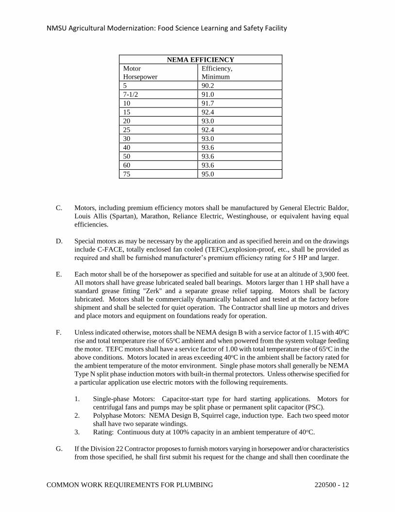
NMSU Agricultural Modernization: Food Science Learning and Safety Facility
COMMON WORK REQUIREMENTS FOR PLUMBING 220500 - 12
NEMA EFFICIENCY
Motor
Horsepower
Efficiency,
Minimum
5 90.2
7-1/2 91.0
10 91.7
15 92.4
20 93.0
25 92.4
30 93.0
40 93.6
50 93.6
60 93.6
75 95.0
C. Motors, including premium efficiency motors shall be manufactured by General Electric Baldor,
Louis Allis (Spartan), Marathon, Reliance Electric, Westinghouse, or equivalent having equal
efficiencies.
D. Special motors as may be necessary by the application and as specified herein and on the drawings
include C-FACE, totally enclosed fan cooled (TEFC),explosion-proof, etc., shall be provided as
required and shall be furnished manufacturer’s premium efficiency rating for 5 HP and larger.
E. Each motor shall be of the horsepower as specified and suitable for use at an altitude of 3,900 feet.
All motors shall have grease lubricated sealed ball bearings. Motors larger than 1 HP shall have a
standard grease fitting "Zerk" and a separate grease relief tapping. Motors shall be factory
lubricated. Motors shall be commercially dynamically balanced and tested at the factory before
shipment and shall be selected for quiet operation. The Contractor shall line up motors and drives
and place motors and equipment on foundations ready for operation.
F. Unless indicated otherwise, motors shall be NEMA design B with a service factor of 1.15 with 400C
rise and total temperature rise of 65oC ambient and when powered from the system voltage feeding
the motor. TEFC motors shall have a service factor of 1.00 with total temperature rise of 65oC in the
above conditions. Motors located in areas exceeding 40oC in the ambient shall be factory rated for
the ambient temperature of the motor environment. Single phase motors shall generally be NEMA
Type N split phase induction motors with built-in thermal protectors. Unless otherwise specified for
a particular application use electric motors with the following requirements.
1. Single-phase Motors: Capacitor-start type for hard starting applications. Motors for
centrifugal fans and pumps may be split phase or permanent split capacitor (PSC).
2. Polyphase Motors: NEMA Design B, Squirrel cage, induction type. Each two speed motor
shall have two separate windings.
3. Rating: Continuous duty at 100% capacity in an ambient temperature of 40oC.
G. If the Division 22 Contractor proposes to furnish motors varying in horsepower and/or characteristics
from those specified, he shall first submit his request for the change and shall then coordinate the
NMSU Agricultural Modernization: Food Science Learning and Safety Facility
COMMON WORK REQUIREMENTS FOR PLUMBING 220500 - 13
change with Division 26 and shall pay all additional charges in connection with the change.
2.4 ELECTRICAL WIRING AND CONTROL EQUIPMENT
A. All wiring and conduit shall be furnished and installed as scheduled in Section 22 0549, Plumbing
and Electrical Installation Coordination, unless otherwise noted or directed.
B. The Contractor shall coordinate completely with all trades and Sub-Contractors as required to ensure
that all necessary components of control work are included and fully understood. No additional cost
shall accrue to the Owner as a result of lack of such coordination.
C. The piping system may be bonded to the electrical ground bus at the electrical service equipment,
but shall not under any circumstances be used as the main grounding electrode for the electrical
service.
2.5 PAINTING
A. All finish painting of plumbing systems and equipment will be under "Painting," unless equipment is
hereinafter specified to be provided with factory applied finish coats.
B. All equipment shall be provided with factory applied prime finish, unless otherwise specified.
C. Touch-Up: If the factory finish on any equipment is damaged in shipment or during construction of
the building, the equipment shall be refinished.
2.6 COUPLING GUARDS
A. All flexibly connected pumps shall be provided with protective steel coupling guards.
2.7 IDENTIFICATION OF VALVES
A. Each valve shall be provided with a stamped metal tag secured to the valve. Tag shall indicate the
valve number, the service and function of each valve and system valve numbers and designations
shall be coordinated with existing valve identification. In addition, the Contractor shall provide a
valve chart, typed neatly on 8-1/2" x 11" sheets, listing the number, size, location, function, normal
operating position, on each valve installed under Division 22. Valves shall be listed by system, i.e.
domestic cold water, hot water, chilled water etc. Tags shall be stamped brass 1-1/2" diameter, and
secured to valves by heavy copper figure eight hooks, braided stainless steel wire anchor, or other
approved means.
B. Division 22 valve tags shall be coordinated with Division 21 and Division 23 valve tags for
coordinated format between each Division.
C. Valve tags shall be coordinated with existing facility valve tags and Contractor shall obtain a copy of
existing facility valve chart and provide updated valve chart to the Owner’s Representative.
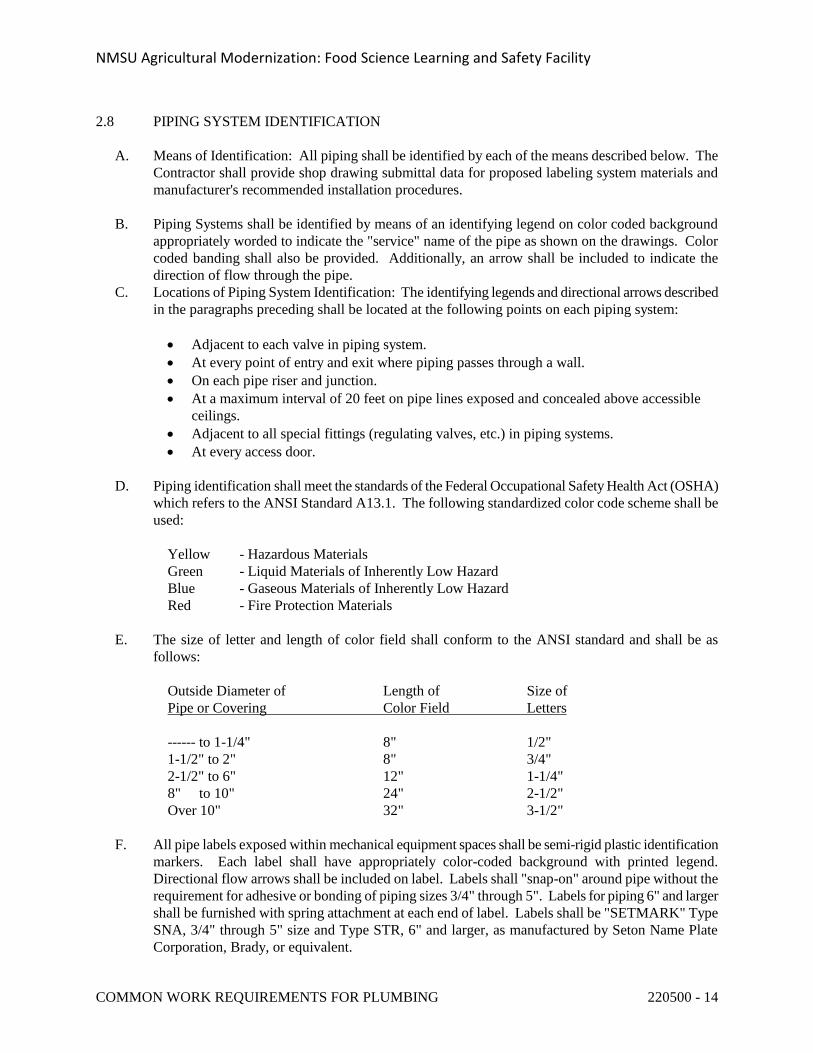
NMSU Agricultural Modernization: Food Science Learning and Safety Facility
COMMON WORK REQUIREMENTS FOR PLUMBING 220500 - 14
2.8 PIPING SYSTEM IDENTIFICATION
A. Means of Identification: All piping shall be identified by each of the means described below. The
Contractor shall provide shop drawing submittal data for proposed labeling system materials and
manufacturer's recommended installation procedures.
B. Piping Systems shall be identified by means of an identifying legend on color coded background
appropriately worded to indicate the "service" name of the pipe as shown on the drawings. Color
coded banding shall also be provided. Additionally, an arrow shall be included to indicate the
direction of flow through the pipe.
C. Locations of Piping System Identification: The identifying legends and directional arrows described
in the paragraphs preceding shall be located at the following points on each piping system:
Adjacent to each valve in piping system.
At every point of entry and exit where piping passes through a wall.
On each pipe riser and junction.
At a maximum interval of 20 feet on pipe lines exposed and concealed above accessible
ceilings.
Adjacent to all special fittings (regulating valves, etc.) in piping systems.
At every access door.
D. Piping identification shall meet the standards of the Federal Occupational Safety Health Act (OSHA)
which refers to the ANSI Standard A13.1. The following standardized color code scheme shall be
used:
Yellow - Hazardous Materials
Green - Liquid Materials of Inherently Low Hazard
Blue - Gaseous Materials of Inherently Low Hazard
Red - Fire Protection Materials
E. The size of letter and length of color field shall conform to the ANSI standard and shall be as
follows:
Outside Diameter of Length of Size of
Pipe or Covering Color Field Letters
------ to 1-1/4" 8" 1/2"
1-1/2" to 2" 8" 3/4"
2-1/2" to 6" 12" 1-1/4"
8" to 10" 24" 2-1/2"
Over 10" 32" 3-1/2"
F. All pipe labels exposed within mechanical equipment spaces shall be semi-rigid plastic identification
markers. Each label shall have appropriately color-coded background with printed legend.
Directional flow arrows shall be included on label. Labels shall "snap-on" around pipe without the
requirement for adhesive or bonding of piping sizes 3/4" through 5". Labels for piping 6" and larger
shall be furnished with spring attachment at each end of label. Labels shall be "SETMARK" Type
SNA, 3/4" through 5" size and Type STR, 6" and larger, as manufactured by Seton Name Plate
Corporation, Brady, or equivalent.
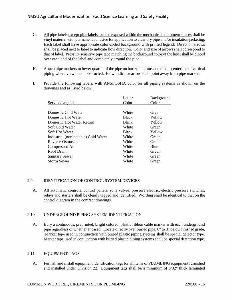
NMSU Agricultural Modernization: Food Science Learning and Safety Facility
COMMON WORK REQUIREMENTS FOR PLUMBING 220500 - 15
G. All pipe labels except pipe labels located exposed within the mechanical equipment spaces shall be
vinyl material with permanent adhesive for application to clear dry pipe and/or insulation jacketing.
Each label shall have appropriate color-coded background with printed legend. Direction arrows
shall be placed next to label to indicate flow direction. Color and size of arrows shall correspond to
that of label. Pressure sensitive pipe tape matching the background color of the label shall be placed
over each end of the label and completely around the pipe.
H. Attach pipe markers to lower quarter of the pipe on horizontal runs and on the centerline of vertical
piping where view is not obstructed. Flow indicator arrow shall point away from pipe marker.
I. Provide the following labels, with ANSI/OSHA color for all piping systems as shown on the
drawings and as listed below:
Letter Background
Service/Legend Color Color
Domestic Cold Water White Green
Domestic Hot Water Black Yellow
Domestic Hot Water Return Black Yellow
Soft Cold Water White Green
Soft Hot Water Black Yellow
Industrial (non potable) Cold Water White Green
Reverse Osmosis White Green
Compressed Air White Blue
Roof Drain White Green
Sanitary Sewer White Green
Storm Sewer White Green
2.9 IDENTIFICATION OF CONTROL SYSTEM DEVICES
A. All automatic controls, control panels, zone valves, pressure electric, electric pressure switches,
relays and starters shall be clearly tagged and identified. Wording shall be identical to that on the
control diagram in the contract drawings.
2.10 UNDERGROUND PIPING SYSTEM IDENTIFICATION
A. Bury a continuous, preprinted, bright colored, plastic ribbon cable marker with each underground
pipe regardless of whether encased. Locate directly over buried pipe, 6" to 8" below finished grade.
Marker tape used in conjunction with buried plastic piping systems shall be special detector type.
Marker tape used in conjunction with buried plastic piping systems shall be special detection type.
2.11 EQUIPMENT TAGS
A. Furnish and install equipment identification tags for all items of PLUMBING equipment furnished
and installed under Division 22. Equipment tags shall be a minimum of 3/32" thick laminated
NMSU Agricultural Modernization: Food Science Learning and Safety Facility
COMMON WORK REQUIREMENTS FOR PLUMBING 220500 - 16
phenolic plastic.
2.12 ACCESS DOORS
A. Provide all access doors required for access to valves, controls, or other items for which access is
required for either operation or servicing. All costs incurred through failure to perform this function
as the proper sequence of this work shall be borne by the Contractor. The type of access door shall
be coordinated with Architect as required by the room finish schedule. Acoustical tile access doors
shall be equal to Krueger Style B, Style A for acoustical plaster, Style C-CE for sidewall drywall or
plaster construction.
B. Access doors shall be not less than 24" x 24" in size except that larger panels shall be furnished
where required, and panels in tile or other similar patterned ceilings shall have dimensions
corresponding to the tile or pattern module.
C. Where access doors are installed in walls required to have a specific fire rating, the access door
installed shall be a fire rated access door with UL label, as manufactured by Milcor or equivalent.
Access door in 1-hour construction shall be Class C and access doors in 2-hour construction shall be
Class B.
PART 3 - EXECUTION
3.1 COOPERATION WITH OTHER TRADES
A. The Contractor shall refer to other parts of these specifications covering the work of other trades
which must be carried on in conjunction with the plumbing work so that the construction operations
can proceed without harm to the Owner from interference, delay, or absence of coordination. The
Contractor shall be responsible for the size and accuracy of all openings.
3.2 DRAWINGS
A. The plumbing drawings show the general arrangement of all piping, fixtures, equipment, etc., and
shall be followed as closely as actual building construction and work of other trades will permit.
Whenever discrepancies occur between plans and specifications, the most stringent shall govern. All
Contract Documents, including but not limited to Division 21 Fire Suppression, Division 23 HVAC,
and Division 26 Electrical shall be considered as part of the work insofar as this information
furnishes the Contractor with details relating to design and construction of the building.
Architectural and Structural drawings shall take precedence over the plumbing, HVAC and fire
suppression drawings. Install plumbing fixtures, floor drains, floor sinks, roof drains, etc. in
locations as indicated on Architectural drawings. Because of the small scale of the plumbing,
HVAC and fire suppression drawings, it is not possible to indicate all offsets, fittings and accessories
which may be required. The Contractor shall investigate the structural and finish conditions
affecting the work and shall arrange his work accordingly, providing such fittings, valves, and
accessories as may be required to meet such conditions. Should conditions necessitate a
rearrangement of piping, such departures and the reasons therefore shall be submitted by the
Contractor for review in the form of detailed drawings showing the proposed changes. No such
NMSU Agricultural Modernization: Food Science Learning and Safety Facility
COMMON WORK REQUIREMENTS FOR PLUMBING 220500 - 17
changes shall be made without the prior written approval. All changes shall be marked on the set of
record drawings by the Contractor.
B. Should any doubt or question arise in respect to the true meaning of the drawings or specifications,
the question shall be submitted in writing.
C. Installation of all plumbing equipment and piping systems shall be arranged to provide all clearances
required for equipment operation, service, and maintenance, including minimum clearances required
by applicable codes, manufacturer's installation instructions and as necessary for proper clearance in
front of all electrical panels as defined by the National Electric Code (NEC). Piping systems shall
not be routed through or above electrical equipment room or electrical equipment space designed
within equipment rooms.
D. The Contractor's attention is directed to the unique architectural design features and consideration
associated with this facility which will require significantly greater levels of coordination and
cooperation for the work furnished and installed under Division 22 with the associated architectural,
structural, and electrical work than is normally necessary for a more typical facility.
E. The installation of all concealed plumbing systems shall be carefully arranged to fit within the
available space without interference with adjacent structural and electrical systems. The Contractor
shall make all necessary provisions for penetrations of piping, including sleeves and blockouts in
structural systems. The exact location of all exposed plumbing systems; access doors; piping
exposed within finished areas; and other equipment and devices as applicable, shall be coordinated
with the Architect, who shall have final authority for the acceptance of the work as it specifically
relates to the architectural aesthetic design requirements for the facility. In no instance shall the
building vapor barrier system be penetrated by the plumbing system installation without written
approval.
3.3 FIELD MEASUREMENTS
A. The Contractor shall verify the dimensions and conditions governing his work at the building. No
extra compensation shall be claimed or allowed on account of differences between actual
dimensions, including dimensions of equipment, fixtures and materials furnished, and those
indicated on the drawings. Contractor shall examine adjoining work, on which his work is
dependent for perfect efficiency, and shall report any work which must be corrected. Coordination
of all plumbing work within the building will be the direct responsibility of the Contractor. Review
of submittal data in accordance with paragraph "Submittals" shall in no manner relieve the
Contractor of responsibility for the proper installation of the plumbing work within the available
space. Installation of equipment and systems within the building space shall be carefully coordinated
by the Contractor with all building trades. Each contractor shall so harmonize his work with that of
the several other trades that it may be installed in the most direct and workmanlike manner without
hindering or handicapping the other trades. Piping interferences shall be handled by giving
precedence to pipe lines which require a stated grade for proper operation. Sewer lines shall take
precedence over water lines in determination of elevations. In all cases, lines requiring a stated
grade for their proper operation shall have precedence over electrical conduit and ductwork.
Installation of plumbing, HVAC and fire suppression equipment within the ceiling cavity shall be in
the following order of priority: plumbing waste lines; roof drains; supply, return, outside air,
makeup, and exhaust ductwork; steam and condensate piping; fire sprinkler mains; fire sprinkler
branch piping and sprinkler runouts; heating hot water and chilled water piping; domestic hot and
NMSU Agricultural Modernization: Food Science Learning and Safety Facility
COMMON WORK REQUIREMENTS FOR PLUMBING 220500 - 18
cold water; control piping, wiring and conduit; miscellaneous special piping systems.
3.4 EQUIPMENT SUPPORT
A. Contractor shall provide support for equipment to the building structure. Contractor shall furnish all
necessary structures, inserts, sleeves, and hanging devices for installation of mechanical and
plumbing equipment, ductwork and piping, etc. Contractor shall completely coordinate installation
of such devices with all trades and Sub-Contractors. Contractor must further verify that the devices
and supports are adequate as intended and do not overload the building's structural components in
any way.
3.5 PROTECTION OF MATERIALS AND EQUIPMENT
A. The Contractor shall be responsible for the protection of all work, materials and equipment furnished
and installed under this section of the specifications, whether incorporated in the building or not.
B. Plumbing equipment and materials, including piping, valves and fittings, etc., shall be protected
from damage and contamination. Equipment and materials shall not be stored outside and exposed
to weather and ambient conditions without appropriate protection measures and without the approval
of the Architect. Equipment and materials shall be delivered to the jobsite and maintained while on
the jobsite with all openings, controls and control panels covered with caps, with heavy duty
polyethylene wrap or other proper means. Equipment and materials where stored within the building
shall be protected at all times from construction damage and contamination from dust, dirt, debris,
and especially during fireproofing, painting and gypboard sanding and finishing. Unprotected
equipment and piping will require special field cleaning by the Contractor prior to acceptance by the
Architect and Owner’s Representative.
C. The Contractor shall provide protection for all work where necessary and shall be responsible for all
damage done to property, equipment and materials. Storage of materials within the building shall be
approved by the Architect prior to such storage.
D. Pipe openings shall be closed with caps or plugs, or covered to prevent lodgment of dirt or trash
during the course of installation. At the completion of the plumbing work, fixtures and materials
shall be cleaned and polished thoroughly and delivered in a condition satisfactory to the Architect.
3.6 TRENCHING AND BACKFILLING
A. All excavation, trenching and backfilling required for the plumbing installation shall be provided by
this Contractor.
3.7 MANUFACTURER'S INSTRUCTIONS
A. All equipment shall be installed in strict accordance with recommendations of the manufacturer. If
such recommendations conflict with plans and specifications, the Contractor shall report such
conflicts to the Architect, who shall make such compromises as he deems necessary and desirable.
NMSU Agricultural Modernization: Food Science Learning and Safety Facility
COMMON WORK REQUIREMENTS FOR PLUMBING 220500 - 19
3.8 CONCRETE BASES AND HOUSEKEEPING PADS
A. Concrete bases and housekeeping pads shall be installed under all pieces of plumbing equipment
unless specifically deleted by the specifications or drawings.
B. Contractor shall be responsible for the accurate dimensions of all pads and bases and shall furnish
and install all vibration isolators, anchor bolts, etc.
C. Contractor shall provide concrete housekeeping pad foundations for all floor mounted equipment
installed under this section unless otherwise shown on the drawings. All concrete bases and
housekeeping pads shall conform to the requirements specified under Division 3, Concrete, portions
of these specifications. Pad foundations shall be 4" high minimum, unless otherwise indicated on
the drawings. Chamfer edges shall be 1". Faces shall be free of voids and rubbed smooth with
carborundum block after stripping forms. Tops shall be level. Provide dowel rods in floor for lateral
stability and anchorage.
D. Equipment anchor bolts shall be set in a galvanized pipe or sheet metal sleeves 1" larger than bolt
diameter. Anchor bolts shall be high strength steel J shape. Anchor bolt design shall be arranged
and paid for by the Contractor.
E. Machinery bases, bed plates, sole plates, or vibration isolation units shall be carefully aligned,
shimmed, leveled, then grouted in place with commercial non-shrink grout. When a flexible
coupling is employed as a part of the drive train, the coupling shall be aligned before the machinery
base is grouted.
3.9 EQUIPMENT FURNISHED UNDER OTHER SECTIONS OF THESE SPECIFICATIONS
A. Certain items of mechanical equipment as listed on the drawings and/or specifications will be
furnished under other sections of this specification for mechanical rough-in and connection under
Division 22, including plumbing, domestic water and waste, cooling water, compressed air, etc. All
required plumbing services, including connection of such services to equipment shall be provided
under Division 22.
3.10 ALIGNMENT OF FLEXIBLE COUPLINGS
A. Flexible couplings between motors and driven equipment shall be aligned by the qualified service
technician after the equipment is installed and ready for operation. Proper aligning shall be provided
within manufacturer's maximum alignment tolerance at equipment operating conditions and
temperature. Alignment shall follow unit manufacturer's written procedures using approved dial
indication methods for parallel and angular alignment. The Contractor shall provide written
certification that each device has been so aligned.
3.11 LUBRICATION
A. The Contractor shall provide all oil for the operation of all equipment until acceptance. The
Contractor shall be held responsible for all damage to bearings while the equipment is being
NMSU Agricultural Modernization: Food Science Learning and Safety Facility
COMMON WORK REQUIREMENTS FOR PLUMBING 220500 - 20
operated by him up to the date of acceptance of the equipment. The Contractor shall protect all
bearings and shafts during installation and shall thoroughly grease the steel shafts to prevent
corrosion. Bearings for items of plumbing equipment shall be marked at each bearing location as to
whether the bearing is a sealed type or relubricable type unit.
3.12 PRESSURE RELIEF DEVICES
A. Pressure relief devices and fusible plugs shall be installed with piping to a safe location in
accordance with Code requirements.
3.13 TESTS
A. Tests shall be conducted in the presence of the designated and authorized Owner's Representative.
The Contractor shall notify the Architect a minimum of one week in advance of scheduled tests.
Requirements for testing are specified under the sections covering the various systems. The
Contractor shall furnish all necessary equipment, materials, and labor to perform the required tests.
3.14 INSTALLATION CHECK
A. An experienced, competent, and authorized representative of the equipment listed below shall visit
the site of the work and inspect, check, adjust if necessary, and approve the equipment installation.
In each case, the equipment supplier's representative shall be present when the equipment is placed
in operation. The equipment supplier's representative shall revisit the job site as often as necessary
until all trouble is corrected and the equipment installation and operation is approved and accepted.
B. Each equipment supplier's representative shall furnish a written report certifying that the equipment
(1) has been properly installed and lubricated; (2) is in accurate alignment; (3) is free from any
undue stress imposed by connecting piping or anchor bolts; and, (4) has been operated under full
load conditions and that it has operated satisfactorily.
C. Equipment requiring installation check includes the following:
End Suction Pumps
Water Softener
Domestic Water Generators
Sump Pump and Sewage Pump Systems
Domestic Water Booster Pump Systems
3.15 OPERATION AND MAINTENANCE INSTRUCTIONS
A. The Contractor shall furnish complete operating and maintenance instructions covering all units of
plumbing equipment fixtures, faucets, etc., herein specified together with parts lists. Equipment
spare parts shall include all components requiring service, including motors, bearings, shafts, etc.
B. See Division 1 for additional requirements concerning manuals, manual distribution, and
maintenance materials.
NMSU Agricultural Modernization: Food Science Learning and Safety Facility
COMMON WORK REQUIREMENTS FOR PLUMBING 220500 - 21
C. Operating and maintenance manuals as required herein shall be submitted for review and distribution
to the Owner not less than two (2) weeks prior to the date scheduled for the Contractor to provide
Operating and Maintenance Instructions to the Owner as specified herein.
D. Upon completion of all work and all tests, Contractor shall furnish the necessary skilled labor and
helpers for operating the plumbing systems and equipment for a period of five (5) days of eight (8)
hours each. During this period, the Contractor shall instruct the Owner or his representative fully in
the operations, adjustment and maintenance of all equipment furnished. Contractor shall provide at
least two weeks notice in advance of this period, with a written schedule of each training session, the
subject of the session, the Contractors' representatives who plan to attend the session, and the time
for each session.
E. Operational test shall be conducted by the Contractor with the assistance of the equipment
manufacturer's representative or service technician. Test shall be conducted in the presence of the
designated and authorized Owner's Representative.
3.16 CERTIFICATIONS
A. Before receiving final payment, the Contractor shall certify in writing that all equipment furnished
and all work done is in compliance with the contract documents and all applicable codes. Submit
certifications and acceptance certificates, including proof of delivery of O&M manuals, spare parts
required, and equipment warranties which shall be bound with O&M manuals.
3.17 INTERRUPTING SERVICES
A. The Contractor shall coordinate the installation of all plumbing work onsite and within the building
in order to minimize interference with the operation of existing building and onsite mechanical,
plumbing, fire protection, and utility systems during construction. Connections to existing systems
requiring the interruption of service within the building shall be carefully coordinated with the
Owner to minimize system downtimes. Requests for the interruption of existing services shall be
submitted in writing a minimum of two (2) weeks before the scheduled date. Absolutely no
interruption of the existing services will be permitted without written review and authorization.
3.18 CONSTRUCTION PHASING AND SCHEDULE
A. All work furnished and installed under Division 22 of this Specification shall be provided in
accordance with the project schedule and phase requirements as described on the Architectural
Drawings and Specifications.
3.19 PLUMBING SYSTEM SHUTDOWN AND REACTIVATION
A. The Contractor shall shutdown existing facility plumbing equipment and piping systems as required
for installation of the project plumbing construction work. As a part of the required work, the
Contractor shall drain down the existing systems and after completion of new work and pressure
testing of systems, the Contractor shall refill the systems and re-establish proper system circulation,
NMSU Agricultural Modernization: Food Science Learning and Safety Facility
COMMON WORK REQUIREMENTS FOR PLUMBING 220500 - 22
remove all air from piping system and equipment, and place system in full and proper operation.
3.20 OPERATION PRIOR TO ACCEPTANCE
A. Operation of equipment and systems installed by the Division 22 Contractor for the benefit of the
Owner prior to substantial completion will be allowed providing a written agreement between the
Owner and the Contractor has established warranty and other responsibilities to the satisfaction of
both parties.
B. Operation of equipment and systems installed by the Division 22 Contractor, for the benefit of the
Contractor, except for the purposes of testing and balancing will not be permitted without a written
agreement between the Owner and the Contractor establishing warranty and other responsibilities.
3.21 SITE VISITS AND OBSERVATION OF CONSTRUCTION
A. The design professional shall make periodic visits to the project site at various stages of construction
in order to observe the progress and quality of various aspects of the Contractor's work, in order to
determine in general if such work is proceeding in accordance with the Contract Documents. This
observation, however, shall in no way release the Contractor from his complete responsibility to
supervise, direct, and control all construction work and activities. The design team has no authority
over, or a responsibility to means, methods, techniques, sequences, or procedures of construction
provided by the Contractor or for safety precautions and programs, or for failure by the Contractor to
comply with all law, regulations, and codes.
B. Prior to the "Final" observation visit, the attached "Final Observation Checklist" shall be completed
by the Contractor. Any non-applicable items shall be marked "N/A." The completed form shall be
submitted, indicating that all necessary items are complete and requesting a final observation within
10 days. The Contractor shall be notified of any uncompleted items within seven (7) days. A
resubmittal of the form and a new final observation request by the Contractor is required if the form
is returned and noted as incomplete.
END OF SECTION 220500
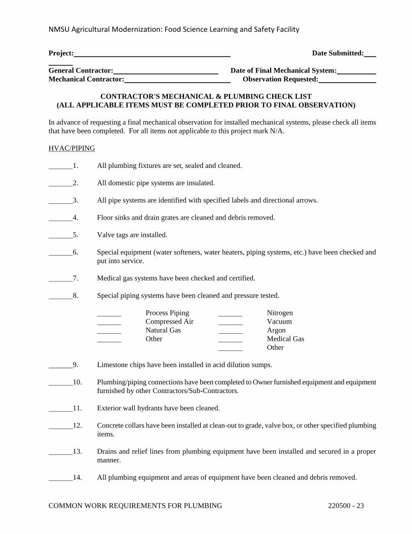
NMSU Agricultural Modernization: Food Science Learning and Safety Facility
COMMON WORK REQUIREMENTS FOR PLUMBING 220500 - 23
Project: Date Submitted:
General Contractor: Date of Final Mechanical System:
Mechanical Contractor: Observation Requested:
CONTRACTOR'S MECHANICAL & PLUMBING CHECK LIST
(ALL APPLICABLE ITEMS MUST BE COMPLETED PRIOR TO FINAL OBSERVATION)
In advance of requesting a final mechanical observation for installed mechanical systems, please check all items
that have been completed. For all items not applicable to this project mark N/A.
HVAC/PIPING
1. All plumbing fixtures are set, sealed and cleaned.
2. All domestic pipe systems are insulated.
3. All pipe systems are identified with specified labels and directional arrows.
4. Floor sinks and drain grates are cleaned and debris removed.
5. Valve tags are installed.
6. Special equipment (water softeners, water heaters, piping systems, etc.) have been checked and
put into service.
7. Medical gas systems have been checked and certified.
8. Special piping systems have been cleaned and pressure tested.
Process Piping Nitrogen
Compressed Air Vacuum
Natural Gas Argon
Other Medical Gas
Other
9. Limestone chips have been installed in acid dilution sumps.
10. Plumbing/piping connections have been completed to Owner furnished equipment and equipment
furnished by other Contractors/Sub-Contractors.
11. Exterior wall hydrants have been cleaned.
12. Concrete collars have been installed at clean-out to grade, valve box, or other specified plumbing
items.
13. Drains and relief lines from plumbing equipment have been installed and secured in a proper
manner.
14. All plumbing equipment and areas of equipment have been cleaned and debris removed.
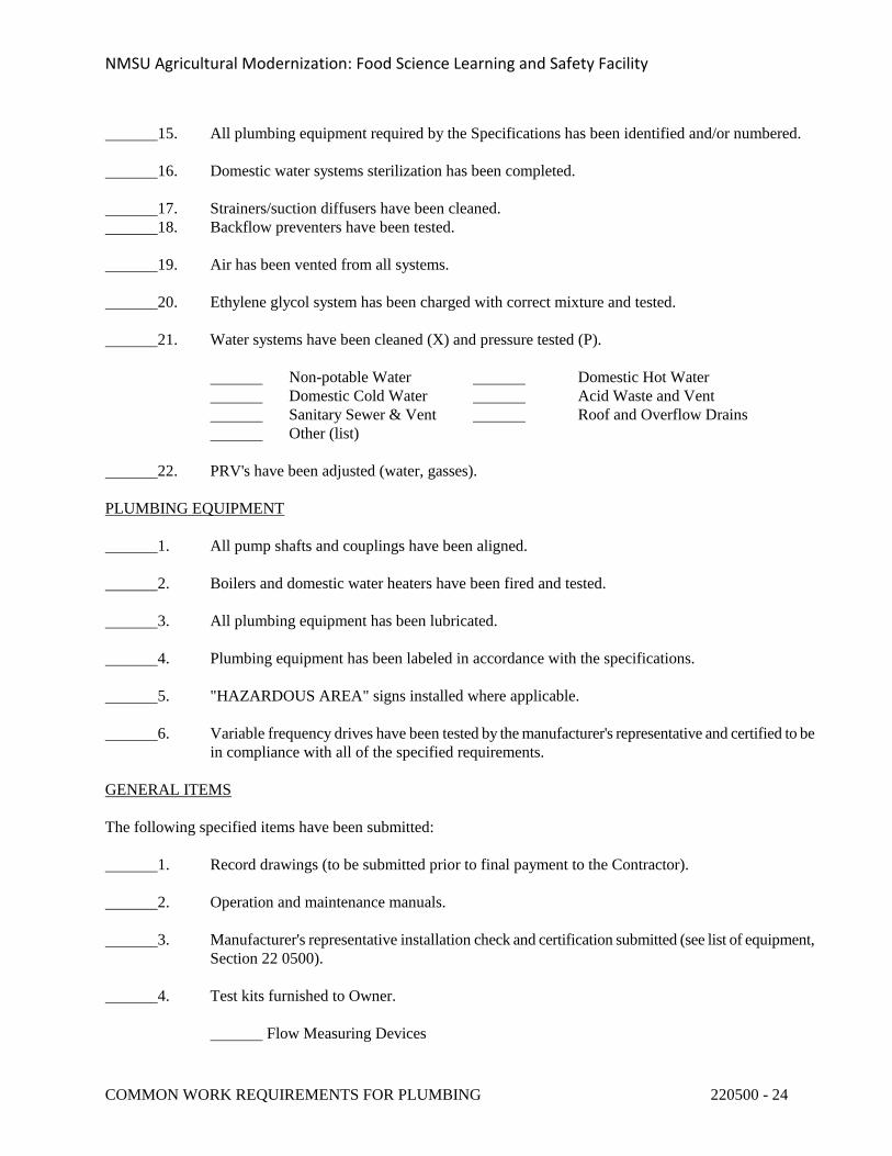
NMSU Agricultural Modernization: Food Science Learning and Safety Facility
COMMON WORK REQUIREMENTS FOR PLUMBING 220500 - 24
15. All plumbing equipment required by the Specifications has been identified and/or numbered.
16. Domestic water systems sterilization has been completed.
17. Strainers/suction diffusers have been cleaned.
18. Backflow preventers have been tested.
19. Air has been vented from all systems.
20. Ethylene glycol system has been charged with correct mixture and tested.
21. Water systems have been cleaned (X) and pressure tested (P).
Non-potable Water Domestic Hot Water
Domestic Cold Water Acid Waste and Vent
Sanitary Sewer & Vent Roof and Overflow Drains
Other (list)
22. PRV's have been adjusted (water, gasses).
PLUMBING EQUIPMENT
1. All pump shafts and couplings have been aligned.
2. Boilers and domestic water heaters have been fired and tested.
3. All plumbing equipment has been lubricated.
4. Plumbing equipment has been labeled in accordance with the specifications.
5. "HAZARDOUS AREA" signs installed where applicable.
6. Variable frequency drives have been tested by the manufacturer's representative and certified to be
in compliance with all of the specified requirements.
GENERAL ITEMS
The following specified items have been submitted:
1. Record drawings (to be submitted prior to final payment to the Contractor).
2. Operation and maintenance manuals.
3. Manufacturer's representative installation check and certification submitted (see list of equipment,
Section 22 0500).
4. Test kits furnished to Owner.
Flow Measuring Devices
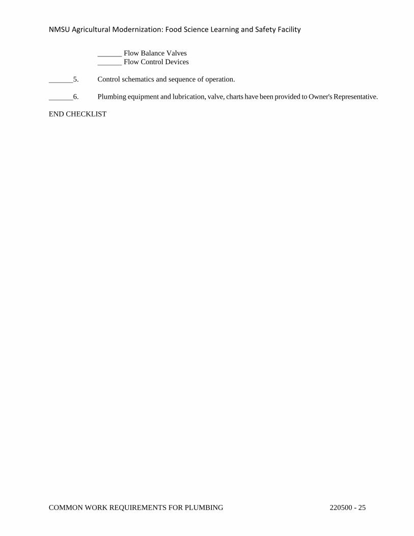
NMSU Agricultural Modernization: Food Science Learning and Safety Facility
COMMON WORK REQUIREMENTS FOR PLUMBING 220500 - 25
Flow Balance Valves
Flow Control Devices
5. Control schematics and sequence of operation.
6. Plumbing equipment and lubrication, valve, charts have been provided to Owner's Representative.
END CHECKLIST
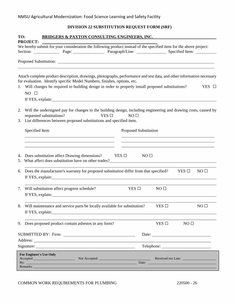
NMSU Agricultural Modernization: Food Science Learning and Safety Facility
COMMON WORK REQUIREMENTS FOR PLUMBING 220500 - 26
DIVISION 22 SUBSTITUTION REQUEST FORM (SRF)
TO: BRIDGERS & PAXTON CONSULTING ENGINEERS, INC.
PROJECT:
We hereby submit for your consideration the following product instead of the specified item for the above project:
Section: Page: Paragraph/Line: Specified Item:
Proposed Substitution:
Attach complete product description, drawings, photographs, performance and test data, and other information necessary
for evaluation. Identify specific Model Numbers, finishes, options, etc.
1. Will changes be required to building design in order to properly install proposed substitutions? YES
NO
If YES, explain:
2. Will the undersigned pay for changes to the building design, including engineering and drawing costs, caused by
requested substitutions? YES NO
3. List differences between proposed substitutions and specified item.
Specified Item Proposed Substitution
4. Does substitution affect Drawing dimensions? YES NO
5. What affect does substitution have on other trades?
6. Does the manufacturer's warranty for proposed substitution differ from that specified? YES NO
If YES, explain:
7. Will substitution affect progress schedule? YES NO
If YES, explain:
8. Will maintenance and service parts be locally available for substitution? YES NO
If YES, explain:
9. Does proposed product contain asbestos in any form? YES NO
SUBMITTED BY: Firm: Date:
Address:
Signature: Telephone:
For Engineer's Use Only
Accepted Not Accepted: Received too Late:
By: Date:
Remarks:
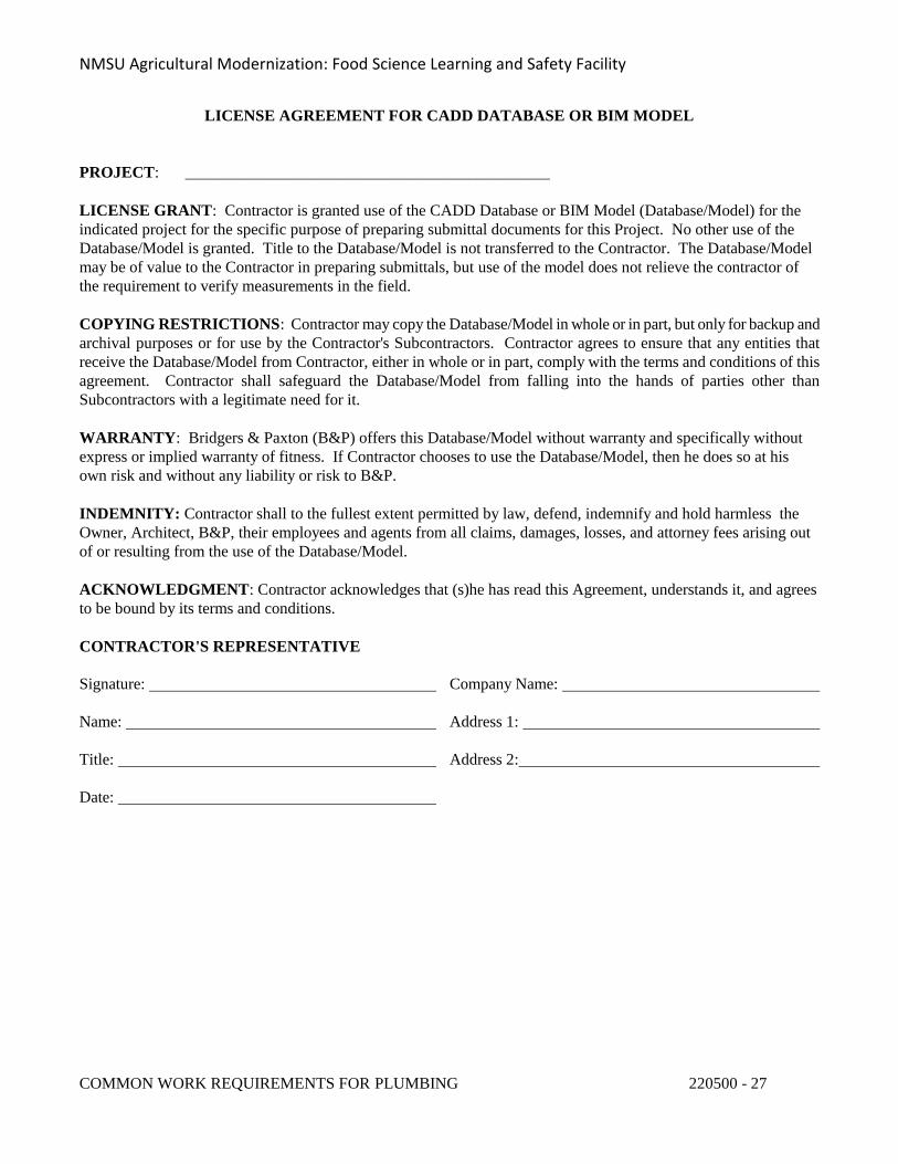
NMSU Agricultural Modernization: Food Science Learning and Safety Facility
COMMON WORK REQUIREMENTS FOR PLUMBING 220500 - 27
LICENSE AGREEMENT FOR CADD DATABASE OR BIM MODEL
PROJECT: _____________________________________________
LICENSE GRANT: Contractor is granted use of the CADD Database or BIM Model (Database/Model) for the
indicated project for the specific purpose of preparing submittal documents for this Project. No other use of the
Database/Model is granted. Title to the Database/Model is not transferred to the Contractor. The Database/Model
may be of value to the Contractor in preparing submittals, but use of the model does not relieve the contractor of
the requirement to verify measurements in the field.
COPYING RESTRICTIONS: Contractor may copy the Database/Model in whole or in part, but only for backup and
archival purposes or for use by the Contractor's Subcontractors. Contractor agrees to ensure that any entities that
receive the Database/Model from Contractor, either in whole or in part, comply with the terms and conditions of this
agreement. Contractor shall safeguard the Database/Model from falling into the hands of parties other than
Subcontractors with a legitimate need for it.
WARRANTY: Bridgers & Paxton (B&P) offers this Database/Model without warranty and specifically without
express or implied warranty of fitness. If Contractor chooses to use the Database/Model, then he does so at his
own risk and without any liability or risk to B&P.
INDEMNITY: Contractor shall to the fullest extent permitted by law, defend, indemnify and hold harmless the
Owner, Architect, B&P, their employees and agents from all claims, damages, losses, and attorney fees arising out
of or resulting from the use of the Database/Model.
ACKNOWLEDGMENT: Contractor acknowledges that (s)he has read this Agreement, understands it, and agrees
to be bound by its terms and conditions.
CONTRACTOR'S REPRESENTATIVE
Signature: Company Name:
Name: Address 1:
Title: Address 2:
Date:
NMSU Agricultural Modernization: Food Science Learning and Safety Facility
TRENCHING AND BACKFILLING FOR PLUMBING 220503 - 1
SECTION 220503 - TRENCHING AND BACKFILLING FOR PLUMBING
PART 1 - GENERAL
1.1 REQUIREMENTS
A. Conform with applicable provisions of the General Conditions, Supplemental General Conditions and the General Requirements.
1.2 SCOPE OF WORK
A. The work in this section includes the furnishing of all labor, materials, equipment, transportation, hauling and services required in connection with the excavation, backfilling, compaction, grading and removal of earth from the site required for the installation of the mechanical work specified herein under Division 22.
1.3 SAFETY REGULATIONS
A. All work performed under this Section shall conform to the requirements of the General Conditions, Supplementary Conditions and Safety Requirements for this type of work.
PART 2 - PRODUCTS
Not Applicable.
PART 3 - EXECUTION
3.1 TRENCHING AND BACKFILLING
A. General Excavation: The Contractor shall perform all excavation of every description and of whatever substances encountered, to the depths indicated on the drawings or as otherwise specified. During excavation, material suitable for backfilling shall be piled in an orderly manner a sufficient distance from the banks of the trench to avoid overloading and to prevent slides or cave-ins. All excavated material not required or suitable for backfill shall be removed and wasted. Berming and grading shall be done as may be necessary to prevent surface water from flowing into trenches or other excavations, and any water accumulating therein shall be removed by pumping or by other approved methods. Sheeting and shoring shall be done as required for the protection of the work and for the safety of personnel.
NMSU Agricultural Modernization: Food Science Learning and Safety Facility
TRENCHING AND BACKFILLING FOR PLUMBING 220503 - 2
B. Trench Excavation: Trenches shall be of adequate width for the proper laying of the pipe, and the banks shall be as nearly vertical as practicable and safe for workmen. The bottom of the trenches shall be accurately graded and bedded to provide uniform bearing and support for each section of the pipe at every point along its entire length. Bell holes and depressions for joints shall be dug after the trench bottom has been graded, and bedded in order that the pipe rests upon the prepared bottom for as nearly its full length as practicable. Care shall be taken not to excavate below the depths indicated. Where rock excavation is required, the rock shall be excavated to a minimum overdepth of 4 inches below the trench depths indicated on the drawings or specified. Overdepths in the rock and common excavation shall be backfilled with coarse sand, fine gravel, or otherwise suitable material. Whenever wet or otherwise unstable soil that is incapable of properly supporting the pipe is encountered in the bottom of the trench, such soil shall be removed to the depth required and the trench backfilled to the proper grade with coarse sand, fine gravel, or other suitable materials, as hereinafter specified.
C. The Contractor shall move trucks and equipment on prescribed roads and keep the roads free from mud, dirt and spillage.
D. If additional material is needed for fill on the project, it shall be furnished by the Contractor.
E. Bracing and Bulkheading: In all excavation work the Contractor shall provide necessary underpinning, bracing, or bulkheading to safeguard the work, the present structures, workmen, the public, and the property, and shall assume all responsibility in connection therewith.
F. Backfilling: The trenches shall not be backfilled until all required pressure tests are performed and until the utilities as installed conform to the requirements specified. The trenches shall be carefully backfilled with materials approved for backfilling; free from large clods of earth or stones. The entire depth of trench shall be backfilled in layers, and each layer shall be spread evenly, wetted to optimum moisture and thoroughly mixed to uniform consistency and compacted to the required maximum density obtainable as the same soil, as determined by ASTM D698.
G. All imported fill required under this section will be furnished by the Contractor. Imported fill will be base course material approved for use by the State Highway Department.
H. Fill material shall be free from trash, lumber or any type of debris which may be detrimental to producing the required density in the fill.
I. The earth beneath all sidewalks and concrete slabs shall be backfilled and compacted to at least 8" below any gravel or sub-base material before the placement of gravel or other base material and shall be coordinated with requirements contained within Division 2.
J. All piping not encased in concrete shall be bedded in sand or fine gravel, without rocks or other foreign material. Bedding material shall be placed around the pipe in accordance with manufacturer’s recommendations. The bedding material shall be distributed around pipe to assure full consolidation.
K. In grass and planted areas, the Contractor shall backfill his excavation to approximately 8"
NMSU Agricultural Modernization: Food Science Learning and Safety Facility
TRENCHING AND BACKFILLING FOR PLUMBING 220503 - 3
below finished grade. Contractor shall coordinate backfill requirements contained in Division 2.
L. The Contractor shall protect from damage all existing underground utilities and utility tunnels indicated on the Contract Drawings. Any damage to such existing utilities or utility tunnels shall be repaired by the Contractor without additional costs to the Owner.
M. Provide density test for trench, backfill in accordance with Division 2 requirements.
END OF SECTION 220503
NMSU Agricultural Modernization: Food Science Learning and Safety Facility
PIPE AND PIPE FITTINGS FOR PLUMBING 220504 - 1
SECTION 220504 - PIPE AND PIPE FITTINGS FOR PLUMBING
PART 1 - GENERAL
1.1 REQUIREMENTS
A. Conform with applicable provisions of the General Conditions, Supplemental General Conditions and General Requirements.
B. Lead Ban: All systems and system components, pipe, fittings, and fixtures delivering water for human consumption shall be lead free.
1. Any product designed for dispensing potable water shall meet both the NSF 61 and NSF 372 test standards via third-party testing and certification.
2. Lead free refers to <0.25% weighted average lead content in relation to wetted surface of pipe, fittings, and fixtures in systems delivering water for human consumption, and solder and flux which does not contain more than 0.2% lead.
1.2 RELATED SECTIONS
A. Section 22 0500, Common Work Requirements for Plumbing.
1.3 SUBMITTAL DATA
A. Contractor shall furnish complete submittal data for all piping materials, including manufacturer's specifications, certifications, class, type and schedule. Submittal data shall additionally be furnished for pipe hangers and supports, pipe sleeves including sealing and fire safing materials and installation.
PART 2 - PRODUCTS
See Division 23, Section 23 0504 – Pipe and Pipe Fittings, for applicable requirements.
PART 3 - EXECUTION
See Division 23, Section 23 0504 – Pipe and Pipe Fittings, for applicable requirements.
END OF SECTION 220504
NMSU Agricultural Modernization: Food Science Learning and Safety Facility
PIPING SPECIALTIES FOR PLUMBING 220505 - 1
SECTION 220505 - PIPING SPECIALTIES FOR PLUMBING
PART 1 - GENERAL
1.1 REQUIREMENTS
A. Contractor shall furnish and install all piping specialties necessary for satisfactory operation of the systems. Conform with applicable provisions of the General Conditions, Supplemental General Conditions and General Requirements.
B. Lead Ban: All systems and system components, pipe, fittings, and fixtures delivering water for human consumption shall be lead free.
1. Any product designed for dispensing potable water shall meet both the NSF 61 and NSF 372 test standards via third-party testing and certification.
2. Lead free refers to <0.25% weighted average lead content in relation to wetted surface of pipe, fittings, and fixtures in systems delivering water for human consumption, and solder and flux which does not contain more than 0.2% lead.
1.2 RELATED SECTIONS
A. Section 22 0500, Common Work Requirements for Plumbing.
B. Section 22 0504, Pipe and Pipe Fittings for Plumbing.
C. Section 22 0523, Valves for Plumbing.
D. Section 22 0700, Plumbing Insulation.
E. Section 22 0549, Plumbing and Electrical Installation Coordination.
1.3 SUBMITTAL DATA
A. The Contractor shall furnish complete submittal data for all piping specialties including manufacturer's specifications, performance characteristics, ratings, installation instructions, certifications and approvals of listing agencies, wiring diagrams, and selection analysis.
NMSU Agricultural Modernization: Food Science Learning and Safety Facility
PIPING SPECIALTIES FOR PLUMBING 220505 - 2
PART 2 - PRODUCTS
See Division 23, Section 23 0505, Piping Specialties.
PART 3 - EXECUTION
See Division 23, Section 23 0505, Piping Specialties.
END OF SECTION 220505
NMSU Agricultural Modernization: Food Science Learning and Safety Facility
VALVES FOR PLUMBING 220523 - 1
SECTION 220523 - VALVES FOR PLUMBING
PART 1 - GENERAL
1.1 REQUIREMENTS
A. All Valves shall conform with current applicable provisions of the General Conditions, Supplemental General Conditions, and General Requirements.
B. All Valves shall meet the current MSS Specifications covering Bronze & Iron Valves. MSS-SP-80, MSS-SP-70, MSS-SP71, MSS-SP-85 where applicable.
C. Lead Ban: All systems and system components, pipe, fittings, and fixtures delivering water for human consumption shall be lead free.
1. Any product designed for dispensing potable water shall meet both the NSF 61 and NSF 372 test standards via third-party testing and certification.
2. Lead free refers to <0.25% weighted average lead content in relation to wetted surface of pipe, fittings, and fixtures in systems delivering water for human consumption, and solder and flux which does not contain more than 0.2% lead.
1.2 RELATED SECTIONS
A. Section 22 0500, Common Work Requirements for Plumbing.
B. Section 22 0504, Pipe and Pipe Fittings for Plumbing.
C. Division 21 for Fire Suppression System.
D. Division 22 for Plumbing.
1.3 SCOPE
A. Contractor shall furnish and install all valves and accessories necessary for satisfactory operation of the systems.
1.4 VALVE REQUIREMENTS
A. All Gate, Globe, Check, Ball valves shall be manufactured by Milwaukee, Nibco, Apollo, Stockham, Powell, Crane, Grinnell, or equivalent.
B. All lubricated plug valves shall be as manufactured by Rockwell, Walworth, Homestead, or equivalent.
NMSU Agricultural Modernization: Food Science Learning and Safety Facility
VALVES FOR PLUMBING 220523 - 2
C. Ball valves shall be utilized in lieu of gate valves and globe valves for all plumbing systems for sizes 2" and smaller.
D. All valves furnish under Division 22 and 23 of the same type shall be products of a single manufacturer [unless otherwise approved by Owner's Representative.
E. Provide gate and globe valves with packing that can be replaced with the valve under full working pressure.
PART 2 - PRODUCTS
See Division 23, Section 23 0523 - Valves, for applicable requirements.
PART 3 - EXECUTION
See Division 23, Section 23 0523 - Valves, for applicable requirements.
END OF SECTION 220523
NMSU Agricultural Modernization: Food Science Learning and Safety Facility
PLUMBING AND ELECTRICAL INSTALLATION COORDINATION 220549 - 1
SECTION 220549 - PLUMBING AND ELECTRICAL INSTALLATION COORDINATION
PART 1 - GENERAL
1.1 REQUIREMENTS
A. Conform with applicable provisions of the General Conditions, Supplemental General Conditions and General Requirements.
1.2 RELATED DIVISIONS AND SECTIONS
A. Section 22 0500, Common Work Requirements for Plumbing.
B. Division 25, Facility Management System.
C. Division 26 for Electrical.
D. Division 28 for Electronic Safety and Security.
1.3 SCOPE
A. It is the intention of this section to summarize the coordination of effort defined in the related sections and divisions of this specification.
B. If there is a conflict between this Section and other Sections and Divisions of this specification, this Section shall be the governing and decisive Section.
C. Make all connections to motors and controls for equipment supplied and/or installed under Division 22 according to Table 1 on the following page.
PART 2 - PRODUCTS
Not Applicable.
PART 3 - EXECUTION
3.1 INSTALLATION
A. No work shall be performed until the reviewed and marked submittal data have been reissued to the Contractor, unless written permission is obtained from the Architect.
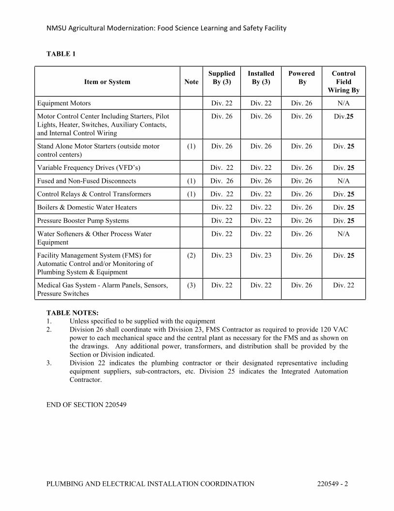
NMSU Agricultural Modernization: Food Science Learning and Safety Facility
PLUMBING AND ELECTRICAL INSTALLATION COORDINATION 220549 - 2
TABLE 1
Item or System NoteSupplied
By (3)Installed
By (3)Powered
By Control
Field Wiring By
Equipment Motors Div. 22 Div. 22 Div. 26 N/A
Motor Control Center Including Starters, Pilot Lights, Heater, Switches, Auxiliary Contacts, and Internal Control Wiring
Div. 26 Div. 26 Div. 26 Div.25
Stand Alone Motor Starters (outside motor control centers)
(1) Div. 26 Div. 26 Div. 26 Div. 25
Variable Frequency Drives (VFD’s) Div. 22 Div. 22 Div. 26 Div. 25
Fused and Non-Fused Disconnects (1) Div. 26 Div. 26 Div. 26 N/A
Control Relays & Control Transformers (1) Div. 22 Div. 22 Div. 26 Div. 25
Boilers & Domestic Water Heaters Div. 22 Div. 22 Div. 26 Div. 25
Pressure Booster Pump Systems Div. 22 Div. 22 Div. 26 Div. 25
Water Softeners & Other Process Water Equipment
Div. 22 Div. 22 Div. 26 N/A
Facility Management System (FMS) for Automatic Control and/or Monitoring of Plumbing System & Equipment
(2) Div. 23 Div. 23 Div. 26 Div. 25
Medical Gas System - Alarm Panels, Sensors, Pressure Switches
(3) Div. 22 Div. 22 Div. 26 Div. 22
TABLE NOTES:1. Unless specified to be supplied with the equipment2. Division 26 shall coordinate with Division 23, FMS Contractor as required to provide 120 VAC
power to each mechanical space and the central plant as necessary for the FMS and as shown on the drawings. Any additional power, transformers, and distribution shall be provided by the Section or Division indicated.
3. Division 22 indicates the plumbing contractor or their designated representative including equipment suppliers, sub-contractors, etc. Division 25 indicates the Integrated Automation Contractor.
END OF SECTION 220549
NMSU Agricultural Modernization: Food Science Learning and Safety Facility
PLUMBING INSULATION 220700 - 1
SECTION 220700 - PLUMBING INSULATION
PART 1 - GENERAL
1.1 REQUIREMENTS
A. Conform with applicable provisions of the General Conditions, Supplemental General Conditions and General Requirements.
B. The Midwest Insulation Contractors Association and Industrial Insulation Standards, Latest Edition, shall be utilized as a standard for the work provided under this specification.
C. Materials shall conform to applicable ASTM standards.
1.2 RELATED SECTIONS
A. Section 22 0500, Common Work Requirements for Plumbing.
B. Section 22 0504, Pipe and Pipe Fittings for Plumbing.
1.3 SCOPE
A. All condensate pipe and fittings, domestic hot water pipe including and circulating hot water, interior roof drains including roof drain bowls, interior overflow roof drains including overflow roof drain bowls, domestic cold water including soft cold water piping, water piping located outdoors exposed to ambient freezing conditions.
B. Equipment covering, including heat exchangers, storage tanks, and pumps.
C. Underground Piping Systems.
D. Plastic Piping Systems.
1.4 FITTINGS
A. All fittings except as otherwise specified, shall be insulated with the same material and thickness as specified for the pipe.
B. Unions, flanges and valves on hot water, will not require insulation.
1.5 TESTING
A. All piping shall be tested in accordance with the applicable Specification Sections, before any insulation is applied.
NMSU Agricultural Modernization: Food Science Learning and Safety Facility
PLUMBING INSULATION 220700 - 2
PART 2 - PRODUCTS
2.1 INSULATION
A. Insulation shall be as manufactured by Owens-Corning Fiberglas, Knauf, CertainTeed, Johns Manville, or Armstrong, or equivalent, and shall be equal to that specified below. Insulation and all materials on the interior and exterior surfaces of ducts, pipes, and equipment shall have a composite fire and smoke hazard rating not exceeding: Flame spread - 25; fuel contribution - 50; smoke developed - 50, as determined in accordance with ASTM Standard E-84. All insulation materials used for valves and fittings shall have the same ratings as the pipe insulation. Information must be submitted by means of manufacturer's literature showing that the proposed materials conform to above specification without exception.
B. Fiberglass pipe insulation shall be rigid molded and non-combustible with 'K' factor of 0.23 at 75oF. Jacket shall be all service (ASJ) vapor barrier jacket with white kraft paper reinforced with glass fiber yarn and bonded to aluminum foil, secured with self sealing longitudinal laps and butt strips. Johns Manville 'Micro-Lok' or equivalent.
C. Hydros Calcium Silicate insulation shall be rigid molded, non-combustible per ASTME 136, conforming to ASTM 533, asbestos-free with 'K' factor of 0.40 at 300oF., maximum service temperature 1200oF., compression strength (block) minimum of 200 PSI to produce 5% compression at 1-1/2" thickness. Johns Manville 'Thermo-12 Gold' or equivalent.
D. Fiberglass rigid board insulation for equipment shall conform to ASTM C612 with 'K' factor of 0.23 at 75oF, R=8.0 minimum, 3.0 pound per cubic foot density. Provide vapor barrier jacket (FSK) with aluminum foil reinforced with fiberglass yarn and laminated to fire-resistant kraft, secured with UL listed pressure sensitive tape and outward clinched expanded staples and vapor barrier mastic. Johns Manville 'Spin-Glas' or equivalent.
E. Elastomeric foam insulation for piping and equipment shall be flexible, cellular, molded or sheet, conforming to ASTM C534, with 'K' factor of 0.28 at 75oF., maximum service temperature of 220oF., maximum flame spread rating of 25 and maximum smoke development rating of 50 (3/4" thickness and less). Connections shall be made using manufacturer's approved waterproof vapor barrier retarder adhesive. Provide outdoor U.V. protective coating on all insulation exposed to ambient conditions.
2.2 FITTINGS
A. Valves and fittings, where required to be insulated, shall be covered with the same insulation material and thickness as specified for the pipe insulation and finished with PVC covers.
B. Valves and fittings with systems specified to be covered with metal or canvas, or polyvinyl chloride (PVC) jacket shall be covered with material to match piping system jacketing.
C. Polyvinyl chloride (PVC) preformed fitting covers with fiberglass inserts shall be used on valves and fittings, except where metal or canvas jacket is required for piping system. PVC fitting covers shall be Zeston 2000 or equivalent, gloss white and shall have a composite fire and smoke hazard rating not exceeding; flame spread - 25; smoke development - 50.
NMSU Agricultural Modernization: Food Science Learning and Safety Facility
PLUMBING INSULATION 220700 - 3
Connections shall be made using tacks and pressure sensitive color matching vinyl tape. Seams shall be on the bottom side of pipe and fittings.
2.3 METAL JACKETING
A. Metal jacket shall be 0.010-inch smooth Type 304 stainless steel, smooth. Provide moisture barrier lining for service temperatures 60oF and less, except where applied over insulation with All Service (ASJ) vapor barrier jacket. Stainless steel jacket shall be installed where specified herein or otherwise indicated on the drawings.
2.4 PVC JACKETING
A. PVC jacketing shall be Zeston 2000 or equivalent, gloss white, 0.020 inch thickness, minimum, and shall have a composite fire and smoke hazard rating not exceeding; flame spread -25; smoke development -50. Connection shall be made using tacks and pressure sensitive color matching vinyl tape. Seams shall be on the bottom side of pipe and fittings.
2.5 CANVAS JACKETING
A. Canvas jacketing shall be UL listed fabric, six ounce per square yard, plain weave cotton, treated with fire retardant lagging adhesive.
2.6 PIPE HANGERS AND SUPPORTS
A. See Specification Section 22 0504 for requirements associated with hangers and supports for piping systems.
B. All insulated piping systems shall be provided with individual hangers sized to encircle the insulation. Hangers for domestic cold water and roof drains may be installed under the insulation, provided that the vapor barrier system for cold piping and the hanger rods are protected from the formation of condensation by application of a heavy coating of vapor barrier mastic material.
C. Insulated piping supported by means of trapeze hangers or roller type hangers shall not rest directly on the hanger or support.
D. The insulation at hangers, trapezes and supports shall be protected by means of galvanized steel insulation half diameter support shields. Provide insulation insert between support shield and piping for piping size 1-1/2" and larger. Insulation inserts shall be heavy density calcium silicate molded insulation. Insulation inserts shall be the following minimum lengths. Factory fabricated thermal pipe shield as manufactured by Pipe Shields, Inc., and specified in Section 22 0504, may be used at Contractor's option.
Pipe Size, In. Insert Length1-1/2" to 2-1/2" 10" Long
NMSU Agricultural Modernization: Food Science Learning and Safety Facility
PLUMBING INSULATION 220700 - 4
3" to 6" 12" Long8" to 10" 16" Long12" and larger 22" Long
2.7 PIPE SLEEVES
A. See Specification Section 22 0504 for requirements associated with pipe sleeves for piping penetrations for building walls and frames.
B. Pipe sleeves shall be provided at penetrations through concrete and masonry construction and at fire rated and smoke rated walls and penetrations when required to comply with UL approved penetration assembly. Insulated piping passing through fire walls and smoke walls shall be provided with UL approved fire safing insulation to match the required insulation thickness and the space between the piping penetration and the adjacent wall construction shall be sealed air tight with UL approved fireproof caulking material. Pipe penetration arrangement and installation requirements shall match the applicable UL approved penetration assembly details.
PART 3 - EXECUTION
3.1 DOMESTIC HOT WATER PIPING
A. Domestic hot water piping with operating temperatures of 140oF and less, including and recirculating hot water piping shall be insulated with 1-inch thick fiberglass preformed pipe insulation with All Service Jacket (ASJ). Fittings shall be finished with PVC fitting covers.
B. Insulation thickness for domestic and service water systems operating in excess of 140oF, shall be 1-inch thick fiberglass preformed pipe insulation with All Service Jacket (ASJ) for piping 3/4" through 3" size and 1-1/2" thick for piping 4" and larger. Fittings shall be finished with PVC fitting covers.
C. All voids formed by support saddles or other mounting or support hardware shall be filled with insulation.
3.2 DOMESTIC COLD WATER AND ROOF DRAINS
A. Domestic cold water piping including soft cold water piping shall be insulated with 1-inch thick fiberglass preformed pipe insulation with All Services Jacket (ASJ). Fittings shall be finished with PVC fitting covers.
B. Roof drain bowls and horizontal roof drain piping shall be insulated with 1-inch thick fiberglass insulation as specified for domestic cold water piping.
C. Overflow roof drain bowls and horizontal overflow roof drain piping shall be insulated with 1-inch thick fiberglass insulation as specified for domestic cold water piping.
D. All voids formed by support saddles or other mounting or support hardware shall be filled with insulation.
NMSU Agricultural Modernization: Food Science Learning and Safety Facility
PLUMBING INSULATION 220700 - 5
3.3 HANDICAP LAVATORY AND SINKS
A. Domestic hot and cold water piping and P-traps exposed below handicapped lavatories and sinks shall be insulated with HANDI LAV-GUARD insulation kits which satisfy ANSI A117.1 requirements. Insulation shall have a flexible vinyl finish which protects against burning and cushions impact.
B. Countertop sinks indicated within the Architectural drawings to be handicap-compliant shall have an off-centered drain opening and a maximum sink depth of 7-inches.
3.4 PLASTIC PIPING SYSTEMS
A. Plastic piping systems, including but not limited to polypropylene/CPVC, RO/DI piping, acid waste, vent piping and PVC piping, installed within building return air plenums shall be insulated with 1/2" thick fiberglass preformed pipe insulation with All Service Jacket (ASJ). Fittings shall be insulated with preformed insulation fittings or, where preformed fittings are unavailable, neatly insulated with fiberglass duct wrap with white vinyl jacket.
B. All voids formed by support saddles or other mounting or support hardware shall be filled with insulation.
3.5 SUCTION DIFFUSERS AND PUMP IMPELLER HOUSING
A. Suction diffusers and pump impeller housing on plumbing domestic hot water pumps except fractional horsepower hot water recirculating pump located at domestic water heaters shall be insulated with minimum 1-1/2" thickness fiberglass board with vapor barrier jacket and cover with metal jacket. Fill voids in fiberglass board housing with fiberglass batt insulation. Insulation housing shall be removable for pump maintenance without damaging the insulation and provide removable access cover for suction diffuser strainer casing cover.
3.6 METAL JACKETING
A. Metal jacketing shall be installed on all field insulated plumbing equipment and on plumbing piping systems exposed within the mechanical equipment spaces, that are installed exposed below 8 feet above the floor, on outdoor insulated piping, inside accessible tunnels, and where noted on the drawings.
B. The jacketing shall be applied with joints overlapped 2" and located to shed water. Joints and seams shall be caulked with an approved weatherproof caulking when located outdoors. The insulation shall be banded 12" on centers or screwed in place 3" on centers.
C. Fittings and valves shall have insulation covered with metal jacket, as specified herein. Fittings and valves on exterior piping and ductwork shall be covered with metal jacketing to match pipe and duct covers.
NMSU Agricultural Modernization: Food Science Learning and Safety Facility
PLUMBING INSULATION 220700 - 6
3.7 PVC JACKETING
A. PVC jacketing shall be installed on all field insulated plumbing equipment and on all piping systems exposed within the mechanical equipment spaces, that are installed below 8 feet above the floor, where exposed to physical damage, and where noted on the drawings and specifications, except where metal or canvas jacketing is required.
B. Jacketing shall be secured in place in an approved manner by means of tacks and pressure sensitive tape.
C. Fittings and valves shall have insulation covered with PVC pre-molded PVC fittings to match jacketing, as specified below.
D. PVC jacketing shall not be permitted for use on exterior piping systems.
3.8 CANVAS JACKETING
A. Canvas jacketing shall be installed on all field insulated plumbing equipment and on all piping systems where noted on the drawings and specifications, except where metal or PVC jacketing is required.
B. Canvas jacket shall be adhered in place with fire retardant lagging adhesive and coating, to form a wrinkle free smooth continuous surface.
3.9 TERMINATION OF INSULATION
A. The termination of all insulation on pipes, at uninsulated valve connections, or unions, flexible connections, etc., shall be beveled and finished.
3.10 FACTORY INSULATED EQUIPMENT
A. Domestic water storage tanks, heat exchangers, and other equipment as specified in the equipment schedules on the drawings shall be factory insulated.
3.11 VICTAULIC COUPLINGS
A. Where Victaulic type couplings or similar piping systems are used, all couplings shall be insulated with insulation materials and thickness equal to the piping system. Insulation of couplings shall be as specified herein for fittings.
3.12 VESSELS, TANKS, AND EQUIPMENT
A. Insulate hot vessels, tank, and equipment, including shell and tube heat exchangers, storage tanks, plate and frame heat exchangers, etc., with 1" thickness, 3 pound density fiberglass insulation for surface temperatures from 40oF to 60oF, 2" thickness, 3 pound density fiberglass insulation for surface temperatures from 60oF to 400oF, and 4" thickness, calcium silicate
NMSU Agricultural Modernization: Food Science Learning and Safety Facility
PLUMBING INSULATION 220700 - 7
insulation for surface temperatures in excess of 400oF to 1200oF. Insulation board shall be scored, beveled, or mitered to provide tight joints and shall be secured in place by mechanical pin and clip fasteners and insulation bonding adhesive applied to underside surfaces or with bands. All joints, cracks, seams and voids shall be filled with insulation bedding compound and finished to smooth surface, provide corner beads to protect edges of insulation. Cover insulation with metal jacket as specified herein. Bevel insulation away from all flanges, nameplates, and access fittings. Provide removable and re-usable insulation cover for all access fittings and manhole covers.
B. Plate and frame heat exchangers shall be provided with a removable and re-usable insulation cover consisting of rigid insulation secured to galvanized steel metal frame-work and covered with metal jacket as specified herein.
3.13 HEAT TRACED PIPING
A. All piping installed outdoors subject to freezing which is provided with heat tracing system as specified in Section 22 0505, including domestic water piping exposed to freezing conditions, make-up water piping to Division 22 and Division 23 equipment, including valves and fittings, shall be insulated with fiberglass sectional pipe insulation, as specified for chilled water piping, and finished with metal jacket. Oversize insulation as required to accommodate electric heat tracing system. Waterproof metal jacket joints and seams with silicone caulking.
3.14 UNDERGROUND PIPING
A. Underground domestic hot water piping shall be insulated using pre-insulated piping and protective covering suitable for underground use, as specified in Section 23 2119.
END OF SECTION 220700
NMSU Agricultural Modernization: Food Science Learning and Safety Facility
DOMESTIC WATER PIPING 221100 - 1
SECTION 221100 - DOMESTIC WATER PIPING
PART 1 - GENERAL
1.1 REQUIREMENTS
A. Conform with the applicable provisions of the General Conditions, Supplemental General Conditions, and the General Requirements.
B. Lead Ban: All systems and system components, pipe, fittings, and fixtures delivering water for human consumption shall be lead free.
1. Any product designed for dispensing potable water shall meet both the NSF 61 and NSF 372 test standards via third-party testing and certification.
2. Lead free refers to <0.25% weighted average lead content in relation to wetted surface of pipe, fittings, and fixtures in systems delivering water for human consumption, and solder and flux which does not contain more than 0.2% lead. Solder shall be 95/5 tin antimony, alloy Sb5, conforming to FS QQ-S-571 and NSF 61.
1.2 RELATED SECTIONS
A. Section 22 0500, Common Work Requirements for Plumbing
B. Section 22 0504, Pipe and Pipe Fittings for Plumbing.
C. Section 22 0505, Piping Specialties for Plumbing.
D. Section 22 0523, Valves for Plumbing.
E. Section 22 0700, Plumbing Insulation.
F. Section 22 6801, Onsite Utilities, Plumbing.
G. Division 25, Facility Management System.
H. Section 22 6801 and Division 33 for Outside Utilities.
1.3 SCOPE
A. A complete domestic cold water, hot water, recirculating hot water, and make-up water system including water heaters, pumps, thermal expansion tanks, backflow protection, shock absorbers, and associated miscellaneous accessories. This section shall include all work within the building to a point approximately 5'-0" outside the building, or as otherwise indicated.
B. Coordinate with Division 33 for site utility drawings and specifications.
NMSU Agricultural Modernization: Food Science Learning and Safety Facility
DOMESTIC WATER PIPING 221100 - 2
PART 2 - PRODUCTS
2.1 PIPING
A. Domestic water piping below grade or slab-on-grade shall be Type L soft copper, ASTM B88. Copper piping 2" and smaller shall be soft tubing and 2-1/2" thru 4" shall be either soft tubing or hard pipe. Domestic water piping 6" and larger including soft water piping below grade within the building and to a point approximately 5'-0" from the building shall be ductile iron pressure pipe, minimum 150 PSIG working pressure with mechanical joints. Wrap all underground copper pipe and fittings with minimum 20 mil polyethylene with minimum 50% overlay, provide for taping.
B. Domestic water piping above grade within the building 4" and smaller shall be Type L hard drawn copper, ASTM B88. Domestic water piping including soft water piping, larger than 4" shall be copper as specified.
C. Proper insulating fittings, as specified in Section 22 0504, shall be installed to prevent electrolytic action between steel and copper piping connections.
2.2 FITTINGS
A. Fittings for copper piping shall be wrought copper or cast brass conforming to ANSI B16.22 and B16.23, with 95-5 solder joints, as specified in Section 22 0504.
B. Mechanically formed tee connections and couplings for copper piping system as specified in Section 22 0504, may be utilized where approved.
C. Fittings for galvanized steel pipe shall be screwed Class 150, standard galvanized malleable iron conforming to ANSI B16.3.
D. Fittings for ductile iron pipe shall be flanged or mechanical joint conforming to ANSI/AWWA C110 and C111, Class 250 minimum, cement lined, with bituminous coating.
2.3 FLANGES
A. Flanges for copper piping systems shall be Class 150 wrought copper or cast brass conforming to ANSI B16.24.
B. Flange connections for valves and equipment shall match the rating and drilling of the valves and equipment furnished.
C. Flanges for galvanized steel piping system shall be galvanized cast or malleable iron Class 125, standard threaded plain face companion flanges for flanged connections in threaded piping systems.
D. Gaskets shall be 1/16" thick ring type or full face non-asbestos material suitable for the temperatures and pressure application.
NMSU Agricultural Modernization: Food Science Learning and Safety Facility
DOMESTIC WATER PIPING 221100 - 3
E. Flange bolting shall be carbon steel machine bolts or studs and hex nuts, ASTM A307, Grade B.
2.4 JOINTS
A. Joints in copper piping system shall be made using approved "lead-free" solder and flux as described herein and approved by all applicable codes and regulations. Surfaces to be soldered shall be cleaned bright by manual or mechanical means.
B. All joints shall be properly fluxed with a non-corrosive "lead-free" type flux manufactured to approved standards, Federal Specification QQ-S-517. Joints for copper piping systems for cold water 3" and smaller and hot water 2" and smaller shall be made using composition 95-5 tin-antimony solder. Composition 15% silver solder shall be used for all other piping sizes and for all underground joints.
2.5 SHOCK ABSORBERS
A. Furnish and install factory sealed shock absorbers conforming to Federal Specification WW-P-541 at locations shown on the drawings and/or as outlined by Plumbing Drainage Institute Standard WH-201. Josam, Precision, Jay R. Smith, Wade, Watts, Zurn or equivalent.
2.6 DOMESTIC HOT WATER GENERATING EQUIPMENT
A. Hot water generators and associated auxiliary equipment shall be as specified on the equipment schedule on the drawings.
B. Furnish and install approved expansion tank on cold water make-up supply to hot water generating equipment as recommended by manufacturer or as shown on the drawings and specified in the plumbing equipment and fixture schedule on the drawings, Amtrol, Wilkins, or approved equal.
C. The Contractor shall provide the services of a qualified factory-trained representative to supervise hot water generation system start-up and instruct the Owner’s operating personnel for a minimum of eight (8) hours. A full one (1) year service warranty, including all parts and labor, shall be provided by the Contractor.
2.7 VALVES
A. Valves other than automatic control valves are specified in Section 22 0523, Valves.
B. Automatic control valves shall be as specified in Division25, Facility Management System, except for automatic control valves furnished as a part of equipment packages, including hot water generating equipment, as specified on the equipment schedule.
NMSU Agricultural Modernization: Food Science Learning and Safety Facility
DOMESTIC WATER PIPING 221100 - 4
2.8 PUMPS
A. Pumps shall be of the type and capacity listed in the equipment schedule. Pumps shall be selected so that the motors will not overload under any operating condition. Furnish one spare mechanical seal of each size required in conjunction with the pumps furnished under this Contract. All base mounted pumps shall have drain pans with tapped pipe connections and 3/4" drain line extended to floor drain. Pumps shall be installed so that they may be removed without the removal of the associated piping. All pumps for potable water applications shall have bronze or stainless steel body and trim.
B. Domestic water inline re-circulating pumps shall be as specified on the drawings and as manufactured by Armstrong, Bell & Gossett, Taco, Thrush, or equivalent.
C. Manufacturer shall furnish a full one (1) year warranty, including all parts and labor for the water pressure booster pumping system.
2.9 WATER METER
A. See Division 33 for water meters.
B. See Division 25, Facility Management System, for plumbing, meters and instrumentation.
2.10 BACKFLOW PROTECTION
A. All cross-contamination control shall be provided to ensure that no installation of the potable water supply piping system shall be made in a manner that will allow used, unclean, polluted, or contaminated water or substances to enter the domestic potable water system.
B. All backflow devices and assemblies shall be approved by the applicable Administration Authorities and shall be installed according to all applicable codes, regulations, and manufacturer's instructions. Installation shall allow for required access and clearance for required testing, maintenance, and repair.
C. Reduced pressure backflow preventer assembly shall be furnished and installed by the Contractor. Backflow preventer size and arrangement shall be as indicated on the drawings, and shall be as manufactured by Febco, Hersey, Beeco, Watts, Wilkins, or equivalent. All costs, fees, and permits required shall be secured and paid for by the Contractor, unless otherwise indicated.
D. See Section 22 6801 for backflow protection.
E. See Section 23 0504 for backflow preventer required for make-up water connections to HVAC systems.
NMSU Agricultural Modernization: Food Science Learning and Safety Facility
DOMESTIC WATER PIPING 221100 - 5
PART 3 - EXECUTION
3.1 INSTALLATION
A. Piping installation shall conform to the requirements of Section 22 0500, Common Work Requirements for Plumbing and Section 22 0504, Pipe and Pipe Fittings for Plumbing. Installation of specialties shall conform to the requirements of Section 22 0505, Piping Specialties for plumbing.
B. Insulating Fittings: Insulating unions shall be furnished and installed at all connections between dissimilar metals.
C. Valves: Each water service main, branch main and branch to a group of two or more fixtures shall be valved. Stop valves shall be as specified under fixtures.
D. Flexible Connections: If the Contractor uses a pipe material other than copper to connect to the City water main, provide mechanical joints at the connection point and also either a swing joint or expansion joint at a point 5 ft. outside the building to prevent failure of piping caused by differential settling of building and piping systems. The expansion joint material shall be suitable for domestic water usage and compatible with the sterilization chemicals.
3.2 STERILIZATION
A. All new water piping shall be charged with a chlorine solution containing not less than 50 PPM available chlorine. The solution shall remain in the piping for a period of 24 hours, during which time valves shall be opened and closed to permit a small flow of the solution. At the end of 24 hours, the solution shall be tested and must contain a residual of at least 5-10 PPM chlorine. The system shall then be drained and flushed to provide satisfactory potable water before final connection is made to the existing distribution system.
B. The Contractor shall submit a sample of the water, after sterilization and flushing for testing by an approved laboratory. A copy of the acceptable test report shall be submitted to the Architect prior to substantial completion.
3.3 BACKFLOW PROTECTION
A. Protection: All plumbing fixtures, faucets with hose connections, and all other equipment having plumbing connections shall have their water supplies protected against back-siphonage.
B. Testing: Arrange for testing backflow devices as required by the local health authorities.
NMSU Agricultural Modernization: Food Science Learning and Safety Facility
DOMESTIC WATER PIPING 221100 - 6
3.4 TESTS
A. All water piping, hot and cold, shall be made tight under a hydrostatic test pressure of 150 lbs. per square inch and maintained without pressure loss for a minimum of four (4) hours. No caulking of joints will be permitted. Any joint found to leak under this test shall be broken, remade and a new test applied.
END OF SECTION 221100
NMSU Agricultural Modernization: Food Science Learning and Safety Facility
FACILITY NATURAL GAS SYSTEM 221123 - 1
SECTION 221123 - FACILITY NATURAL GAS SYSTEM
PART 1 - GENERAL
1.1 REQUIREMENTS
A. Conform with applicable provisions of the General Conditions and Supplemental General Conditions.
1.2 RELATED SECTIONS
A. Section 22 0500, Common Work Requirements for Plumbing.
B. Section 22 0504, Pipe and Pipe Fittings for Plumbing.
C. Section 22 0505, Piping Specialties for Plumbing.
D. Section 22 0523, Valves for Plumbing.
E. Division 25, Facility Management System.
F. Division 33 and Division 22 for onsite utilities.
1.3 SCOPE
A. Complete building natural gas piping system including meters, regulators, and miscellaneous accessories. This section shall include all work within the building and to a point approximately 5'-0" outside the building, or as otherwise indicated.
PART 2 - PRODUCTS
2.1 PIPING
A. Above ground pipe used for the installation, extension, alteration, and/or repair of any gas piping system shall be black steel pipe ASTM A53 Grade A or B, ERW or BW, standard wall, Schedule 40.
B. All underground gas piping shall be steel or polyethylene plastic piping as specified in Section 22 0523, Valves for Plumbing. All underground steel piping and fittings shall be protected from corrosion by approved coatings or wrapping materials as specified in Section 22 0504, Pipe and Pipe Fittings for Plumbing, and Section 22 6801, Outside Utilities, Plumbing.
2.2 FITTINGS
NMSU Agricultural Modernization: Food Science Learning and Safety Facility
FACILITY NATURAL GAS SYSTEM 221123 - 2
A. Fittings for steel piping 2" and smaller shall be either screwed or welded. Screwed fittings shall be Class 150 standard black malleable iron conforming to ANSI B16.3. Weld fittings shall be either standard weight steel butt-weld fittings conforming to ANSI B16.9, or forged steel socket-weld fittings, 2000 pound Schedule 40 conforming to ANSI B16.11.
B. Fittings for steel piping 2-1/2" and larger shall be standard weight steel butt-weld fittings conforming to ANSI B16.9.
2.3 FLANGES
A. Flanges for steel piping system shall be forged steel, weld neck, or slip-on, 1/16" raised face Class 150 flanges conforming to ANSI B16.5.
B. Flange connections for valves and equipment shall match the rating and drilling of the valves and equipment furnished.
C. Where specifically required by the application, black cast iron Class 125 standard threaded plain face companion flanges may be utilized for flanged connections in threaded piping systems.
D. Gaskets shall be 1/16" thick full face non-asbestos material suitable for the temperatures and pressure application.
E. Flange bolting shall be carbon steel machine bolts or studs and hex nuts, ASTM A307, Grade B.
2.4 VALVES
A. Valves shall be as specified in Section 22 0523, Valves for Plumbing.
B. Valves used in conjunction with gas piping shall be approved for the required service.
2.5 GAS METERS
A. Natural gas meters shall be furnished and installed by the natural gas utility company, unless otherwise indicated on the drawings. All required permits and fees shall be secured and paid for by the Contractor in accordance with Section 22 0500. Gas meter shall be the type and capacity required for the application and shall be located as indicated on the drawings and in accordance with utility company requirements and applicable codes and ordinances.
B. Division 22, Section 22 6801, for natural gas meters.
C. Natural gas sub-meters shall be furnished and installed by the Contractor in accordance with the information shown on the drawings and in the plumbing equipment and fixture schedule on
NMSU Agricultural Modernization: Food Science Learning and Safety Facility
FACILITY NATURAL GAS SYSTEM 221123 - 3
the drawings.
D. See Division 25, Facility Management System, for meters and instrumentation.
E. All natural gas meters shall be preceded by a main gas supply shut-off valve serviceable and accessible outside the building.
2.6 NATURAL GAS REGULATOR
A. Natural gas regulator shall be furnished and installed with the gas meter by the utility company, set for the required gas leaving pressure shown on the drawings.
B. Natural gas appliance and equipment regulators for all gas fired equipment furnished and installed under Division 23 shall be furnished by the equipment manufacturer or supplier and sized for the system inlet pressure and the required appliance operating pressure.
C. Division 22, Section 22 6801, for natural gas meter and regulator.
D. Natural gas regulators, as specified and shown on the drawings, shall be furnished and installed by the Contractor.
2.7 PIPING SUPPORTS
A. Natural gas piping installed on the building roof shall be supported by means of piping supports, especially designed to absorb thermal expansion and contraction of piping installed on built up and single ply membrane roofs. Wood blocks are not acceptable. Four inch and smaller gas piping shall be mounted on Erico Pyramid pipe supports or equivalent, pipe supports with a total weight not to exceed 100 pounds per pipe stand. Larger piping, and all piping requiring roller bearing action for pipe expansion, shall be mounted on Erico Pyramid RPS-H or equivalent, with a total weight not to exceed 1500 pounds per pipe collar support. Pipe support spacing shall be as recommended by manufacturer and as required by Code.
B. Piping hangers and supports shall be in accordance with Section 22 0504, Pipe and Pipe Fittings for Plumbing.
2.8 PAINTING
A. All natural gas piping installed outside the building exposed to the weather [and/or exposed to view] shall be field painted in accordance with the painting sections of this specification.
PART 3 - EXECUTION
NMSU Agricultural Modernization: Food Science Learning and Safety Facility
FACILITY NATURAL GAS SYSTEM 221123 - 4
3.1 INSTALLATION
A. Piping installation shall conform to the requirements of Section 22 0500, Common Work Requirements for Plumbing, and Section 22 0504, Pipe and Pipe Fittings for Plumbing. Installation of specialties shall conform to the requirements of Section 22 0505, Piping Specialties for Plumbing.
B. Installation of piping and equipment shall be in accordance with applicable codes and regulations, including Uniform Plumbing Code and Uniform Mechanical Code, and NFPA No. 54, National Fuel Gas code.
C. No gas piping shall be installed in or on the ground under any building or structure, and all exposed gas piping shall be at least 6-inches above grade. Ferrous gas piping installed underground in exterior locations shall be protected for corrosion as specified herein and in Section 22 0504, Pipe and Pipe Fittings for Plumbing.
D. Gas piping supplying the building or facility shall be provided with a shut-off valve located outside the building and readily accessible. Where gas piping supplies multiple buildings or facilities, each building shall be provided with a shut-off valve as described herein.
3.2 EQUIPMENT AND APPLIANCE CONNECTIONS
A. All gas fired equipment and appliances shall be connected to the gas piping system in an approved manner and shall be furnished with a shut-off valve installed ahead of the unit. Connections shall in no case be less than the unit inlet connection size and shall be rigidly connected, except as otherwise shown on the drawings and allowed by codes and regulations.
3.3 DRIPS
A. Accessible capped drip pockets shall be furnished at low points in piping system, connections to appliances and equipment, and other locations where condensation may tend to collect.
3.4 VENTS
A. All gas regulators and other required devices installed within the building shall be vented to the outside of the building in accordance with manufacturer's requirements, codes, and regulations.
3.5 TESTS
A. All gas piping shall be pressure tested using air, CO2, or nitrogen in accordance with the applicable codes and regulations, including Uniform Plumbing and Mechanical Code as
NMSU Agricultural Modernization: Food Science Learning and Safety Facility
FACILITY NATURAL GAS SYSTEM 221123 - 5
adopted and interpreted by the City of Las Cruces and State of New Mexico, and NFPA No. 54.
END OF SECTION 221123
NMSU Agricultural Modernization: Food Science Learning and Safety Facility
SANITARY WASTE AND VENT PIPING 221316 - 1
SECTION 221316 - SANITARY WASTE AND VENT PIPING
PART 1 - GENERAL
1.1 REQUIREMENTS
A. Conform with applicable provisions of the General Conditions and Special Provisions.
B. Furnish and install all concrete, grout, and other required materials to fill all blockouts and/or sleeves left open for this Contractor's convenience or for the installation of this work.
1.2 RELATED SECTIONS
A. Section 22 0500, Common Work Requirements for Plumbing.
B. Section 22 0504, Pipe and Pipe Fittings for Plumbing.
C. Section 22 0700, Plumbing Insulation.
D. Division 33 for Onsite Utilities Plumbing.
E. Division 25, Facility Management System.
1.3 SCOPE
A. Complete soil, waste, and vent system, and associated miscellaneous accessories. This section shall include all work within the building to a point approximately 5'-0" outside the building, or as otherwise indicated.
B. Coordinate with Division 33 site utility drawings and specifications.
C. Plumbing equipment drains.
PART 2 - PRODUCTS
2.1 PIPING
A. Soil, waste, and vent piping below slab on grade shall be service weight cast iron no hub or bell and plain end pipe, coated inside and outside, conforming to ASTM A-74 and 87 Standards or polyvinyl chloride (PVC) sewer pipe, Schedule 40, conforming to ASTM D3034.
B. Soil, waste, and vent piping above grade shall be either service weight cast iron no hub or bell and plain end pipe, coated inside and outside, conforming to ASTM A-74 and 87 standards or
NMSU Agricultural Modernization: Food Science Learning and Safety Facility
SANITARY WASTE AND VENT PIPING 221316 - 2
polyvinyl chloride (PVC) sewer pipe, Schedule 40, conforming to ASTM D3034. At the Contractor's option or if specifically noted on the drawings, copper DWV pipe may be used. Vent piping 2" and smaller above grade may be Schedule 40 galvanized steel.
C. No-hub cast iron pipe shall conform to CISPI Standard 301 and shall be marked with CISPI Label.
D. All above and/or below ground cast iron pipe and/or fittings shall be marked with the trademark of the Cast Iron Soil Pipe Institute, or have the prior written approval of Bridgers & Paxton Consulting Engineers.
E. Piping for pumped soil and waste systems from the discharge of the sump or sewage ejector pumps to the connection to the gravity flow drainage system shall be schedule 40 galvanized steel or Type L hard drawn copper pipe for above ground installation. When underground piping is required within the building and to point approximately 5'-0" from the building perimeter, the underground piping shall be coated cast iron or ductile iron pressure pipe and fittings with joints blocked, braced, and/or strapped in an approved manner to prevent joint separation under pressure.
2.2 FITTINGS
A. Fittings for cast iron sanitary soil, waste and vent piping system shall be service weight or no-hub cast iron drainage pattern conforming to ASTM C564. Fittings shall be provided to match the required piping system.
B. Fittings for galvanized steel vent system shall be galvanized malleable iron conforming to ANSI B16.4. Fittings for galvanized steel soil and waste piping shall be galvanized drainage pattern.
C. No-Hub pipe fittings shall comply with CISPI Standard 301 and shall be marked with CISPI Label.
D. Fittings for copper piping system shall be solder type drainage pattern conforming to ANSI B16.22 and B16.23.
E. Fittings for PVC piping system shall be Schedule 40 drainage pattern, solvent cement type conforming to ASTM B-2855 or elastomeric seal type conforming to ASTM D-3212.
2.3 JOINTS
A. Joints for cast iron pipe and fittings shall be suitable to match the required piping system and shall be either lead and oakum, double seal compression-type molded neoprene gaskets conforming to ASTM C-564 Standards, and suitable for the class of pipe being jointed, with adhesive type joint lubricant, Tyler "LUBRI/FAST" or equivalent. No-hub coupling shall be minimum four (4) band type with neoprene gasket material conforming to ASTM C-564, and 0.008-inch minimum, Type 304 stainless steel shear ring. Couplings shall be Tyler "Wide Body", Huskey Series 4000, Clamp-All, Mission Heavy Weight, Ideal, or equivalent.
NMSU Agricultural Modernization: Food Science Learning and Safety Facility
SANITARY WASTE AND VENT PIPING 221316 - 3
B. Joints for galvanized steel shall be threaded, made with approved joint compound.
C. Joints for copper shall be soldered using 95-5 composition tin-antimony solder with non-corrosive flux.
D. Joints for PVC piping system shall be either solvent cement type conforming to ASTM D-2855 or elastomeric seal type conforming to ASTM D-3212, except all joints above grade shall be solvent cement.
2.4 PLUMBING EQUIPMENT DRAINS
A. Equipment drain lines shall be either Schedule 40 galvanized steel pipe with galvanized malleable iron fittings or Type M copper tubing with wrought solder fittings. Provide a dielectric union at all connections between ferrous to copper materials.
2.5 DRAINS
A. Floor drains, floor sinks, and interceptors shall be Josam, Rockford, Jay R. Smith, Wade, Watts, Zurn, Mifab, or equivalent, as specified on the drawings, and compatible with the required piping systems.
B. Non water-based trap seal maintenance devices by Jay R. Smith Mfg. Co., Liquidbreaker – The Green Drain, SureSeal, and TrapGuard as specified on the drawings are approved.
2.6 TRAPS AND TAILPIECES
A. Unless otherwise specified, traps shall be copper-alloy adjustable tube type with slip joint inlet and swivel, not less than 20 gauge and without cleanout. Inlets shall have rubber washer and copper alloy nuts for slip joints above the discharge level and swivel joints below the discharge level, metal to metal or metal to plastic type as required for the application. Outlet shall be threaded or socket for solder joint connection as required by the application. Tailpiece shall be copper-alloy to match P-trap. Furnish cast brass wall escutcheon at waste penetration through walls. P-traps, tailpieces, escutcheon, and all piping for above floor exposed installations, including installation within cabinets and casework shall be chrome plated. Underground P-traps shall be coated cast iron as required by the application.
B. Traps and associated trim shall be furnished by the plumbing fixture manufacturer as specified in Section 22 4000 and in the Fixture Schedule on the drawings, or shall be as manufactured by Dearborn, EBC, McGuire, T & S Brass, or equivalent.
2.7 CLEANOUTS
A. Cleanouts shall be as manufactured by Zurn, Jay R. Smith, Watts, Wade, or Josam, and shall be of the same size as the pipe, except that cleanout plugs larger than 4 inches will not be required.
NMSU Agricultural Modernization: Food Science Learning and Safety Facility
SANITARY WASTE AND VENT PIPING 221316 - 4
Cleanouts installed in connection with cast iron soil pipe shall consist of a long sweep, quarter-bend or one or two eighth bends extended to an easily accessible place, or as indicated on the drawings. A standard cleanout fitting, Zurn No. ZN-1400-ZB, with polished bronze top shall be caulked into the hub of the fitting and finished flush with the floor. Heavy duty cleanouts shall be Zurn Z-1474, with integral anchor flanges. Where cleanouts in connection with threaded pipe are shown and are accessible, they shall be cast iron drainage T-pattern, 90 degree branch fittings with square head brass screw plugs of the same size as the pipe up to and including 4 inches. Wall cleanouts in finished areas shall be Zurn No. Z-1460-8 with polished stainless steel or chrome plated metal cover.
B. Cleanouts for acid resistant piping system shall be compatible material for the required piping system.
C. Install cover flush with grade (outside) to avoid tripping hazard.
2.8 MANHOLES
A. See Division 33, Outside Utilities, for manholes.
PART 3 - EXECUTION
3.1 INSTALLATION
A. Piping installation shall conform to the requirements of Section 22 0500, Common Work Requirements for plumbing, and Section 22 0504, Pipe and Pipe Fittings for Plumbing. Installation of specialties shall conform to the requirements of Section 22 0505, Piping Specialties.
B. All soil, waste, and vent piping shall be properly graded and installed in strict accordance with all applicable codes and requirements.
C. Make all changes in direction of drainage piping by use of 45 degree wyes, long turn tee wyes, long sweep quarter bends, sixth, eighth or sixteenth bends. Short turn sanitary tees permissible on horizontal to vertical where space conditions require.
3.2 FLASHINGS
A. Flashing for piping through built-up roofing with lead flashing, weight of not less than four pounds per square foot, extending at least 12" in all directions under roofing and up pipe. Cap flash pipe and turn down inside 1" approximately. Run all pipes extending through roof prior to roof installation. Flashing shall be two-piece type, base and cap flashing.
B. Vinyl Flashing: As an option to lead flashing in vents through roof, the Contractor may use vinyl flashing, 20 mil thickness, ASTM C689-62 tear strength, 0.14 #/Ft. equal to Pasco Manufacturing Co., or equivalent. The flashing shall be installed in accordance with the
NMSU Agricultural Modernization: Food Science Learning and Safety Facility
SANITARY WASTE AND VENT PIPING 221316 - 5
manufacturer's recommendations.
C. Flash piping through the membrane roofing systems with premolded pipe seal elastomeric flashing and sealants that are compatible with EPDM single ply membrane. The flashing material and installation procedure shall be in accordance with the roofing manufacturer's recommendations.
3.3 DRAINS
A. All floor drains, trench drains, and floor sinks shall be installed with grates square with building lines and with the top of grates installed level with adjacent finished floor.
B. The Contractor shall extend drain lines from all equipment requiring drainage, relief valves, and drain pans to the nearest floor drain or floor sink, and shall terminate indirectly with a minimum clearance of one (1) inch or as otherwise required by applicable codes and standards. Relief valve drain lines shall be extended to the nearest floor drain and shall be equal in size to relief valve outlet port.
3.4 TESTS
A. The sanitary soil waste and vent system and condensate drain system shall be tested by filling system with water. System shall remain filled with no loss of water for a minimum of 2 hours. The system water test shall be applied to the drainage and vent systems either in its entirety or in sections. Preliminary testing shall be accomplished as necessary prior to final test.
B. If applied to the entire system, all openings in the piping shall be tightly closed, except the highest opening, and the system filled with water to point of overflow. If the system is tested in sections, each opening shall be tightly plugged except the highest opening of the section under test, and each section shall be filled with water, but no section shall be tested with less than ten (10) feet of water. In testing successive sections, at least the upper ten (10) feet of the next preceding section shall be tested, so that no joint or pipe in the building (except the uppermost ten feet) of the system shall have been submitted to a test of less than a ten (10) foot head of water. The system shall then be tight at all points.
C. Piping for pumped drainage systems shall be pressure tested as specified in Section 22 1100 for water systems as a minimum pressure equal to the system working pressure.
END OF SECTION 221316
NMSU Agricultural Modernization: Food Science Learning and Safety Facility
STAINLESS STEEL SANITARY WASTE AND VENT PIPING 221320 - 1
SECTION 221320 – STAINLESS STEEL SANITARY WASTE AND VENT PIPING
PART 1 - GENERAL
1.1 RELATED DOCUMENTS
A. Drawings and general provisions of the Contract, including General and Supplementary
Conditions and Division 01 Specification Sections, apply to this Section.
1.2 SUMMARY
A. Section Includes:
1. Stainless-steel push fit drain piping and fittings.
2. Specialty pipe fittings.
3. Encasement for underground metal piping.
B. Related Requirements:
1. Section 221313 "Facility Sanitary Sewers" for sanitary sewerage piping and structures
outside the building.
2. Section 221329 "Sanitary Sewerage Pumps" for effluent and sewage pumps.
3. Section 226600 "Chemical-Waste Systems for Laboratory and Healthcare Facilities" for
chemical-waste and vent piping systems.
1.3 INFORMATIONAL SUBMITTALS
A. Seismic Qualification Certificates: For waste and vent piping, accessories, and components, from
manufacturer.
1. Basis for Certification: Indicate whether withstand certification is based on actual test of
assembled components or on calculation.
2. Detailed description of piping anchorage devices on which the certification is based and
their installation requirements.
B. Field quality-control reports.
1.4 FIELD CONDITIONS
A. Interruption of Existing Sanitary Waste Service: Do not interrupt service to facilities occupied by
Owner or others unless permitted under the following conditions and then only after arranging to
provide temporary service according to requirements indicated:
1. Notify Architect no fewer than two days in advance of proposed interruption of sanitary
waste service.
NMSU Agricultural Modernization: Food Science Learning and Safety Facility
STAINLESS STEEL SANITARY WASTE AND VENT PIPING 221320 - 2
2. Do not proceed with interruption of sanitary waste service without Architect's written
permission.
PART 2 - PRODUCTS
2.1 PERFORMANCE REQUIREMENTS
A. Components and installation shall be capable of withstanding the following minimum working
pressure unless otherwise indicated:
1. Soil, Waste, and Vent Piping: 10-foot head of water.
2.2 PIPING MATERIALS
A. Piping materials shall bear label, stamp, or other markings of specified testing agency.
B. Comply with requirements in "Piping Schedule" Article for applications of pipe, tube, fitting
materials, and joining methods for specific services, service locations, and pipe sizes.
2.3 STAINLESS-STEEL DRAINAGE PIPE AND FITTINGS
A. Basis-of-Design Product: Subject to compliance with requirements, provide BLÜCHER; A
WATTS Brand; or pre-approved equal:
1. BLÜCHER; A WATTS brand.
2. Pre-approved equal.
B. Description: Comply with requirements of ASME A112.3.1 and ASTM A 666 drainage pattern.
C. Material: Type 316L stainless steel.
D. Pipe Construction: Seamless with socket and spigot ends for gasket joints; and having piping
manufacturer's EPDM, NBR, or FPM lip-seal rubber gaskets to fit socket groove.
E. Corrosion Resistance: Pipe and fittings acid pickled in a hydrofluoric/nitric acid solution
consisting of 0.5 to 5 percent by volume hydrofluoric acid, and 8 to 20 percent by volume nitric
acid at a temperature of 77 to 140 deg F.
F. Internal Sealing Rings: Internal sealing rings selected according to their application for the
temperature range, marked or color coded for the application. Consult factory for chemical
compatibility of sealing ring materials.
1. Ethylene Propylene Diene Monomer (EPDM): Black, 32 to 212 deg F..
G. Joints: Single or double, socket and spigot ends.
H. Pipe Joint Pressure Data: With hangers.
NMSU Agricultural Modernization: Food Science Learning and Safety Facility
STAINLESS STEEL SANITARY WASTE AND VENT PIPING 221320 - 3
1. NPS 1-1/2 to NPS 12: 7 psig.
I. Pipe Joint Pressure Data: With joint clamp.
1. NPS 1-1/2 to NPS 4: 30 psig.
2. NPS 6: 15 psig.
3. NPS 8: 7 psig.
J. Pipe Joint Pressure Data: With joint clamp and projections.
1. NPS 1-1/2 to NPS 8: 44 psig.
K. Pipe Joint Pressure Data: Vacuum pipe applications.
1. NPS 1-1/2 to NPS 3: Minus 12.3 psig. 2. NPS 4 to NPS 8: Minus 8.7 psig.
PART 3 - EXECUTION
3.1 EARTH MOVING
A. Comply with requirements for excavating, trenching, and backfilling specified in Section 312000
"Earth Moving."
3.2 PIPING INSTALLATION
A. Drawing plans, schematics, and diagrams indicate general location and arrangement of piping
systems.
1. Indicated locations and arrangements were used to size pipe and calculate friction loss,
expansion, pump sizing, and other design considerations.
2. Install piping as indicated unless deviations to layout are approved on coordination
drawings.
B. Install piping in concealed locations unless otherwise indicated and except in equipment rooms
and service areas.
C. Install piping indicated to be exposed and piping in equipment rooms and service areas at right
angles or parallel to building walls. Diagonal runs are prohibited unless specifically indicated
otherwise.
D. Install piping above accessible ceilings to allow sufficient space for ceiling panel removal.
E. Install piping to permit valve servicing.
F. Install piping at indicated slopes.
G. Install piping free of sags and bends.
NMSU Agricultural Modernization: Food Science Learning and Safety Facility
STAINLESS STEEL SANITARY WASTE AND VENT PIPING 221320 - 4
H. Install fittings for changes in direction and branch connections.
I. Install piping to allow application of insulation.
J. Make changes in direction for soil and waste drainage and vent piping using appropriate branches,
bends, and long-sweep bends.
1. Sanitary tees and short-sweep 1/4 bends may be used on vertical stacks if change in
direction of flow is from horizontal to vertical.
2. Use long-turn, double Y-branch and 1/8-bend fittings if two fixtures are installed back to
back or side by side with common drain pipe.
a. Straight tees, elbows, and crosses may be used on vent lines.
3. Do not change direction of flow more than 90 degrees.
4. Use proper size of standard increasers and reducers if pipes of different sizes are connected.
a. Reducing size of waste piping in direction of flow is prohibited.
K. Lay buried building waste piping beginning at low point of each system.
1. Install true to grades and alignment indicated, with unbroken continuity of invert. Place
hub ends of piping upstream.
2. Install required gaskets according to manufacturer's written instructions for use of
lubricants, cements, and other installation requirements.
3. Maintain swab in piping and pull past each joint as completed.
L. Install soil and waste and vent piping at the following minimum slopes unless otherwise indicated:
1. Building Sanitary Waste: 2 percent downward in direction of flow for piping NPS 3 and
smaller; 1 percent downward in direction of flow for piping NPS 4 and larger.
2. Vent Piping: 1 percent down toward vertical fixture vent or toward vent stack.
M. Install stainless-steel piping according to ASME A112.3.1 and applicable plumbing code.
N. Install engineered soil and waste and vent piping systems as follows:
1. Combination Waste and Vent: Comply with standards of authorities having jurisdiction.
2. Reduced-Size Venting: Comply with standards of authorities having jurisdiction.
O. Plumbing Specialties:
1. Install backwater valves in sanitary waster gravity-flow piping.
a. Comply with requirements for backwater valves specified in Section 221319
"Sanitary Waste Piping Specialties."
2. Install cleanouts at grade and extend to where building sanitary drains connect to building
sanitary sewers in sanitary waste gravity-flow piping.
a. Comply with requirements for cleanouts specified in Section 221319 "Sanitary
Waste Piping Specialties."
NMSU Agricultural Modernization: Food Science Learning and Safety Facility
STAINLESS STEEL SANITARY WASTE AND VENT PIPING 221320 - 5
3. Install drains in sanitary waste gravity-flow piping.
a. Comply with requirements for drains specified in Section 221319 "Sanitary Waste
Piping Specialties."
P. Do not enclose, cover, or put piping into operation until it is inspected and approved by authorities
having jurisdiction.
Q. Install sleeves for piping penetrations of walls, ceilings, and floors.
1. Comply with requirements for sleeves specified in Section 220517 "Sleeves and Sleeve
Seals for Plumbing Piping."
R. Install sleeve seals for piping penetrations of concrete walls and slabs.
1. Comply with requirements for sleeve seals specified in Section 220517 "Sleeves and
Sleeve Seals for Plumbing Piping."
S. Install escutcheons for piping penetrations of walls, ceilings, and floors.
1. Comply with requirements for escutcheons specified in Section 220518 "Escutcheons for
Plumbing Piping."
3.3 JOINT CONSTRUCTION
A. Join stainless-steel pipe and fittings with gaskets according to ASME A112.3.1.
3.4 SPECIALTY PIPE FITTING INSTALLATION
A. Transition Couplings:
1. Install transition couplings at joints of piping with small differences in ODs.
2. In Waste Drainage Piping: Shielded, non-pressure transition couplings.
3.5 VALVE INSTALLATION
A. Comply with requirements in Section 220523.12 "Ball Valves for Plumbing Piping,"
Section 220523.13 "Butterfly Valves for Plumbing Piping," Section 220523.14 "Check Valves
for Plumbing Piping," and Section 220523.15 "Gate Valves for Plumbing Piping" for general-
duty valve installation requirements.
B. Shutoff Valves:
1. Install shutoff valve on each sewage pump discharge.
2. Install gate or full-port ball valve for piping NPS 2 and smaller.
3. Install gate valve for piping NPS 2-1/2 and larger.
NMSU Agricultural Modernization: Food Science Learning and Safety Facility
STAINLESS STEEL SANITARY WASTE AND VENT PIPING 221320 - 6
C. Check Valves: Install swing check valve, between pump and shutoff valve, on each sewage pump
discharge.
D. Backwater Valves: Install backwater valves in piping subject to backflow.
1. Horizontal Piping: Horizontal backwater valves. Use normally closed type unless
otherwise indicated.
2. Floor Drains: Drain outlet backwater valves unless drain has integral backwater valve.
3. Install backwater valves in accessible locations.
4. Comply with requirements for backwater valve specified in Section 221319 "Sanitary
Waste Piping Specialties."
3.6 HANGER AND SUPPORT INSTALLATION
A. Comply with requirements for seismic-restraint devices specified in Section 220548 "Vibration
and Seismic Controls for Plumbing Piping and Equipment."
B. Comply with requirements for pipe hanger and support devices and installation specified in
Section 220529 "Hangers and Supports for Plumbing Piping and Equipment."
1. Install stainless-steel pipe hangers for horizontal piping in noncorrosive environments.
2. Install stainless-steel pipe hangers for horizontal piping in corrosive environments.
3. Install stainless-steel pipe support clamps for vertical piping in noncorrosive environments.
4. Install stainless-steel pipe support clamps for vertical piping in corrosive environments.
5. Vertical Piping: MSS Type 8 or Type 42, clamps.
6. Install individual, straight, horizontal piping runs:
a. 100 Feet and Less: MSS Type 1, adjustable, steel clevis hangers.
b. Longer Than 100 Feet: MSS Type 43, adjustable roller hangers.
c. Longer Than 100 Feet if Indicated: MSS Type 49, spring cushion rolls.
7. Multiple, Straight, Horizontal Piping Runs 100 Feet or Longer: MSS Type 44, pipe rolls.
Support pipe rolls on trapeze.
8. Base of Vertical Piping: MSS Type 52, spring hangers.
C. Support horizontal piping and tubing within 12 inches of each fitting, valve, and coupling.
D. Support vertical piping and tubing at base and at each floor.
E. Rod diameter may be reduced one size for double-rod hangers, with 3/8-inch minimum rods.
F. Install hangers for stainless-steel piping with the following maximum horizontal spacing and
minimum rod diameters:
1. NPS 1-1/2: 6.5 feet with 3/8-inch rod.
2. NPS 2: 7 feet with 3/8-inch rod.
3. NPS 3: 8 feet with 3/8-inch rod.
4. NPS 4: 9 feet with 3/8-inch rod.
5. NPS 5: 10 feet with 1/2-inch rod.
6. NPS 6 and NPS 8: 10 feet with 1/2-inch rod.
NMSU Agricultural Modernization: Food Science Learning and Safety Facility
STAINLESS STEEL SANITARY WASTE AND VENT PIPING 221320 - 7
G. Install supports for vertical stainless-steel piping every 10 feet.
H. Support piping and tubing not listed above according to MSS SP-58 and manufacturer's written
instructions.
3.7 CONNECTIONS
A. Drawings indicate general arrangement of piping, fittings, and specialties.
B. Connect soil and waste piping to exterior sanitary sewerage piping. Use transition fitting to join
dissimilar piping materials.
C. Connect waste and vent piping to the following:
1. Plumbing Fixtures: Connect waste piping in sizes indicated, but not smaller than required
by plumbing code.
2. Plumbing Fixtures and Equipment: Connect atmospheric vent piping in sizes indicated, but
not smaller than required by authorities having jurisdiction.
3. Plumbing Specialties: Connect waste and vent piping in sizes indicated, but not smaller
than required by plumbing code.
4. Install test tees (wall cleanouts) in conductors near floor and floor cleanouts with cover
flush with floor.
5. Install horizontal backwater valves in pit with pit cover flush with floor.
6. Comply with requirements for backwater valves cleanouts and drains specified in
Section 221319 "Sanitary Waste Piping Specialties."
7. Equipment: Connect waste piping as indicated.
a. Provide shutoff valve if indicated and union for each connection.
b. Use flanges instead of unions for connections NPS 2-1/2 and larger.
3.8 IDENTIFICATION
A. Identify exposed sanitary waste and vent piping.
B. Comply with requirements for identification specified in Section 220553 "Identification for
Plumbing Piping and Equipment."
3.9 FIELD QUALITY CONTROL
A. During installation, notify authorities having jurisdiction at least 24 hours before inspection must
be made. Perform tests specified below in presence of authorities having jurisdiction.
1. Roughing-in Inspection: Arrange for inspection of piping before concealing or closing-in
after roughing-in and before setting fixtures.
2. Final Inspection: Arrange for final inspection by authorities having jurisdiction to observe
tests specified below and to ensure compliance with requirements.
NMSU Agricultural Modernization: Food Science Learning and Safety Facility
STAINLESS STEEL SANITARY WASTE AND VENT PIPING 221320 - 8
B. Reinspection: If authorities having jurisdiction find that piping will not pass test or inspection,
make required corrections and arrange for reinspection.
C. Reports: Prepare inspection reports and have them signed by authorities having jurisdiction.
D. Test sanitary waste and vent piping according to procedures of authorities having jurisdiction or,
in absence of published procedures, as follows:
1. Test for leaks and defects in new piping and parts of existing piping that have been altered,
extended, or repaired.
a. If testing is performed in segments, submit separate report for each test, complete
with diagram of portion of piping tested.
2. Leave uncovered and unconcealed new, altered, extended, or replaced waste and vent
piping until it has been tested and approved.
a. Expose work that was covered or concealed before it was tested.
3. Roughing-in Plumbing Test Procedure: Test waste and vent piping except outside leaders
on completion of roughing-in.
a. Close openings in piping system and fill with water to point of overflow, but not less
than 10-foot head of water.
b. From 15 minutes before inspection starts to completion of inspection, water level
must not drop.
c. Inspect joints for leaks.
4. Finished Plumbing Test Procedure: After plumbing fixtures have been set and traps filled
with water, test connections and prove they are gastight and watertight.
a. Plug vent-stack openings on roof and building drains where they leave building.
Introduce air into piping system equal to pressure of 1-inch wg.
b. Use U-tube or manometer inserted in trap of water closet to measure this pressure.
c. Air pressure must remain constant without introducing additional air throughout
period of inspection.
d. Inspect plumbing fixture connections for gas and water leaks.
5. Repair leaks and defects with new materials and retest piping, or portion thereof, until
satisfactory results are obtained.
6. Prepare reports for tests and required corrective action.
7. Leave uncovered and unconcealed new, altered, extended, or replaced piping until it has
been tested and approved.
a. Expose work that was covered or concealed before it was tested.
8. Cap and subject piping to static-water pressure of 50 psig above operating pressure, without
exceeding pressure rating of piping system materials.
a. Isolate test source and allow to stand for four hours.
NMSU Agricultural Modernization: Food Science Learning and Safety Facility
STAINLESS STEEL SANITARY WASTE AND VENT PIPING 221320 - 9
b. Leaks and loss in test pressure constitute defects that must be repaired.
9. Repair leaks and defects with new materials and retest piping, or portion thereof, until
satisfactory results are obtained.
10. Prepare reports for tests and required corrective action.
3.10 CLEANING AND PROTECTION
A. Clean interior of piping. Remove dirt and debris as work progresses.
B. Protect sanitary waste and vent piping during remainder of construction period to avoid clogging
with dirt and debris and to prevent damage from traffic and construction work.
C. Place plugs in ends of uncompleted piping at end of day and when work stops.
D. Repair damage to adjacent materials caused by waste and vent piping installation.
3.11 PIPING SCHEDULE
A. Flanges and unions may be used on aboveground pressure piping unless otherwise indicated.
B. Aboveground, soil and waste piping NPS 4 and smaller shall be the following:
1. Stainless-steel pipe and fittings, sealing rings, and gasketed joints.
2. Dissimilar Pipe-Material Couplings: Shielded, nonpressure transition couplings.
C. Aboveground, soil and waste piping NPS 5 and larger shall be the following:
1. Stainless-steel pipe and fittings, sealing rings, and gasketed joints.
2. Dissimilar Pipe-Material Couplings: Shielded, nonpressure transition couplings.
D. Aboveground, vent piping NPS 4 and smaller shall be the following:
1. Stainless-steel pipe and fittings gaskets, and gasketed joints.
2. Dissimilar Pipe-Material Couplings: Shielded, nonpressure transition couplings.
E. Aboveground, vent piping NPS 5 and larger shall be the following:
1. Stainless-steel pipe and fittings gaskets, and gasketed joints.
2. Dissimilar Pipe-Material Couplings: Shielded, nonpressure transition couplings.
F. Underground, soil, waste, and vent piping NPS 4 and smaller shall be the following:
1. Stainless-steel pipe and fittings, gaskets, and gasketed joints.
2. Dissimilar Pipe-Material Couplings: Shielded, nonpressure transition couplings.
G. Underground, soil and waste piping NPS 5 and larger shall be the following:
1. Stainless-steel pipe and fittings, gaskets, and gasketed joints.
NMSU Agricultural Modernization: Food Science Learning and Safety Facility
STAINLESS STEEL SANITARY WASTE AND VENT PIPING 221320 - 10
2. Dissimilar Pipe-Material Couplings: Shielded, nonpressure transition couplings.
END OF SECTION 221320
NMSU Agricultural Modernization: Food Science Learning and Safety Facility
FACILITY ROOF DRAINAGE 221400 - 1
SECTION 221400 - FACILITY ROOF DRAINAGE
PART 1 - GENERAL
1.1 REQUIREMENTS
A. Conform with the applicable provisions of the General Conditions and Special Provisions.
1.2 RELATED SECTIONS
A. Section 22 0500, Common Work Requirements for Plumbing.
B. Section 22 0504, Pipe and Pipe Fittings for Plumbing.
C. Section 22 0700, Plumbing Insulation.
D. Division 33 for onsite plumbing utilities.
1.3 SCOPE
A. A complete roof drainage and overflow roof drainage and area drainage system and associated miscellaneous accessories. This section shall include all work within the building and to a point approximately 5'-0" outside the building, or as otherwise indicated.
B. Coordinate with Division 33 site utility drawings and specifications.
PART 2 - PRODUCTS
2.1 PIPING
A. Pipe, fittings and couplings below grade or slab-on-grade shall be service weight cast iron no hub pipe, coated inside and outside, conforming to ASTM A-74 and 87 Standards or polyvinyl chloride (PVC) sewer pipe Schedule 40, conforming to ASTM D3034.
B. Pipe, fittings and couplings above slab on grade shall be either service weight cast iron no hub pipe, coated inside and outside, conforming to ASTM A-74 and 87 Standards.
C. No-hub cast iron pipe shall conform to CISPI Standard 301 and shall be marked with CISPI Label.
D. All above and/or below ground cast iron pipe and/or fittings shall be marked with the trademark of the Cast Iron Soil Pipe Institute.
NMSU Agricultural Modernization: Food Science Learning and Safety Facility
FACILITY ROOF DRAINAGE 221400 - 2
2.2 FITTINGS
A. Fittings for cast iron pipe shall be service weight or no-hub cast iron drainage pattern, conforming to ASTM C564, coated for underground installation.
B. Fittings for galvanized steel pipe shall be screwed galvanized cast iron or malleable iron drainage pattern.
C. Fittings for DWV copper piping shall be solder type copper or brass.
D. Fittings for PVC piping system shall be Schedule 40 drainage pattern, solvent cement type conforming to ASTM B-2855 or elastomeric seal type conforming to ASTM D-3212.
2.3 JOINTS
A. Joints for cast iron pipe and fittings shall be suitable to match the required piping system and shall be either lead or oakum, or double seal compression-type molded neoprene gaskets conforming to ASTM C-564 Standards, and suitable for the class of pipe being jointed, with adhesive type joint lubricant, Tyler "LUBRI/FAST" or equivalent. No-hub couplings shall be minimum four (4) band type with neoprene gasket material, conforming to ASTM 564, and 0.008-inch minimum, Type 304 stainless steel shear ring. Couplings shall be Tyler "Wide Body," Husky Series 4000, Clamp-All, Mission Heavy Weight, Ideal, or equivalent.
B. Joints for galvanized steel shall be threaded, made with approved joint compound.
C. Joints for copper shall be soldered using 95-5 composition tin-antimony solder with non-corrosive flux.
D. Joints for PVC piping system shall be either solvent cement type conforming to ASTM D-2855 or elastomeric seal type conforming to ASTM D-3212, except all joints above grade shall be solvent cement.
2.4 DRAINS
A. Roof drains and overflow roof drains shall be Froet, J. R. Smith, Josam, Mifab, Sioux Chief, Wade, Watts, Zurn, or equivalent as specified on the drawings and compatible with the required piping system. Drains shall be suitable for the required building construction system and shall be furnished complete with all extensions, receptors, flashings, and accessories required for the complete water-proof installation.
B. Catch basins shall be provided in accordance with the details and specifications shown on the drawings.
2.5 CLEANOUTS
NMSU Agricultural Modernization: Food Science Learning and Safety Facility
FACILITY ROOF DRAINAGE 221400 - 3
A. Cleanouts shall be as manufactured by Froet, J. R. Smith, Josam, Mifab, Sioux Chief, Wade, Watts, Zurn, or equivalent, and shall be of the same size as the pipe, except that cleanout plugs larger than 4 inches will not be required. Cleanouts installed in connection with cast iron soil pipe shall consist of a long sweep, quarter-bend or one or two eighth bends extended to an easily accessible place, or as indicated on the drawings. A standard cleanout fitting, Zurn No. ZN-1400-ZB, with polished bronze top shall be caulked into the hub of the fitting and finished flush with the floor. Heavy duty cleanouts shall be Zurn Z-1474, with integral anchor flanges. Where cleanouts in connection with threaded pipe are shown and are accessible, they shall be cast iron drainage T-pattern, 90-degree branch fittings with square head brass screw plugs of the same size as the pipe up to and including 4 inches. Wall cleanouts in finished areas shall be Zurn No. Z-1460-8 with polished stainless steel or chrome plated metal cover.
2.6 ACCESSORIES
A. Refer to Section 22 1316, Sanitary Waste & Vent Piping, for roof flashing requirements.
2.7 MANHOLES
A. See Division 33 for manholes.
PART 3 - EXECUTION
3.1 INSTALLATION
A. Piping installation shall conform to the requirements of Section 22 0500, Common Work Requirements for Plumbing, and Section 22 0504, Pipe and Pipe Fittings for plumbing. Installation of specialties shall conform to the requirements of Section 22 0505, Piping Specialties for Plumbing.
B. Roof drainage and trench drainage piping shall be properly graded and installed in strict accordance with all applicable codes and requirements. All turns and fittings shall be supported same as for waste and vent piping as specified in Section 22 1300.
3.2 TRENCH DRAINS
A. All area drains shall be installed with grates square with building lines, and with the top of grates installed level with the adjacent finish grade level.
3.3 TESTS
A. The roof drainage and trench drainage system shall be tested by filling system with water. System shall remain filled with no loss of water for a minimum of 2 hours. The system water
NMSU Agricultural Modernization: Food Science Learning and Safety Facility
FACILITY ROOF DRAINAGE 221400 - 4
test shall be applied to the systems either in its entirety or in sections. Preliminary testing shall be accomplished as necessary prior to final test.
B. If applied to the entire system, all openings in the piping shall be tightly closed, except the highest opening, and the system filled with water to point of overflow. If the system is tested in sections, each opening shall be tightly plugged except the highest opening of the section under test, and each section shall be filled with water, but no section shall be tested with less than a ten (10) foot of water. In testing successive sections, at least the upper ten (10) feet of the next preceding section shall be tested, so that no joint or pipe in the building (except the uppermost ten feet) of the system shall have been submitted to a test of less than a ten (10) foot head of water. The system shall then be tight at all points.
END OF SECTION 221400
NMSU Agricultural Modernization: Food Science Learning and Safety Facility
COMPRESSED-AIR SYSTEMS 221500 - 1
SECTION 221500 - COMPRESSED-AIR SYSTEMS
PART 1 - GENERAL
1.1 SUMMARY
A. Section includes
1. Pipe fittings, valves, and accessories2. Filters3. Automatic drain valves4. Torpedo oil/water separators5. Air dryers6. Pressure regulating valves7. Air receivers8. Safety valves9. Air compressors
1.2 SUBMITTALS
A. Submit the following in accordance with subcontract submittal procedures:
1. Manufacturer’s catalog data2. Manufacturer’s installation instructions3. Materials/Parts list4. Operational and Maintenance data5. Warranties6. Certification of welders and qualified welding procedure per Section 01 4444 and 01
4455.7. Welding Inspection Reports, as applicable.
1.3 QUALITY ASSURANCE
A. Manufacturer Qualifications: Company specializing in manufacturing products specified in this section with minimum 5 years’ experience and having maintenance service based within 200 miles radius of installation.
B. Material and Installation: Conform to ASME B31.9, Building Services Piping for systems operating at pressure of 150 psig or less and at temperature of 200°F or less. For systems beyond above pressure and temperature limitations, conform to ASME B31.1, Power Piping unless supplying process air; then use B31.3. The design codes and pressure(s) for this installation are as follows: B31.3; 150 psig.
NMSU Agricultural Modernization: Food Science Learning and Safety Facility
COMPRESSED-AIR SYSTEMS 221500 - 2
1.4 WARRANTIES
A. Provide a minimum of 1-year manufacturer’s warranty, parts and labor, for air compressor system.
PART 2 - PRODUCTS
2.1 PRODUCT OPTIONS AND SUBSTITUTION
A. Alternate products may be accepted; follow Section 01 2500, Substitution Procedures.
2.2 COPPER TUBING AND FITTINGS (up to 2 inches)
A. Tubing: Copper, hard drawn or annealed, ASTM B88, Type L
B. Fittings: Wrought copper, ASME B16.22
C. Joints: Solder, ASTM B32, Alloy Sb5 tin-antimony
2.3 STEEL PIPE AND FITTINGS (over 2 inches)
A. Pipe: Black steel, ASTM A53, Schedule 40
B. Fittings: Steel, ASTM A234, Grade WPB, Schedule 40, butt-welding type, ASME B16.9
C. Joints: Welded
2.4 VALVES
A. Gate Valves: MSS SP-80 Class 150, bronze body, bronze trim, rising stem, handwheel, inside screw, solid wedge disc, solder ends to suit piping.
B. Ball Valves: MSS SP-110 Class 150, bronze, chrome-plated brass ball, full port, teflon seats and stuffing box ring, lever handle, solder or threaded ends to suit piping.
C. Globe Valve: MSS SP-80 Class 150, bronze body, bronze trim, solder or threaded ends to suit piping.
D. Swing Check Valve: MSS SP-80 Class 150, bronze body and cap, bronze swing disc with rubber seat, solder or threaded ends to suit piping.
NMSU Agricultural Modernization: Food Science Learning and Safety Facility
COMPRESSED-AIR SYSTEMS 221500 - 3
2.5 STRAINER
A. “Y” type, Class 150, 20 mesh stainless steel perforated screen, bronze] cast iron body, with blowoff gate valve and plug, solder or threaded ends to suit piping.
2.6 UNIONS AND FLANGES
A. Unions
1. Ferrous Pipe: ASME B16.39, Class 150, malleable iron, threaded unions.2. Copper Tube and Pipe: ASME B16.22, Class 150, bronze unions with soldered joints.
B. Dielectric Unions
1. Union with galvanized or plated steel threaded end, copper solder end, water-impervious isolation barrier.
C. Flanges (N/A to copper)
1. Forged carbon steel, ASTM A105, Class 150
2.7 FLEXIBLE CONNECTOR
A. Manufacturer: Flex-Hose, Pumpsaver Connectors.
B. Braided bronze or stainless steel flexible connector with corrugated metal hose, minimum working pressure 200 psi at 70 degree F, minimum temperature rating 400 degree F, with solder ends to suit piping.
2.8 PREFILTER, HIGH-EFFICIENCY COALESCING
A. Manufacturers:
1. Van Air, Housing Series F200, Filter Grade C2. Pneumatics Products, Housing Series P2001, Filter Grade SU
B. High-efficiency coalescing filter efficiency 99.99 percent at 0.6 microns, maximum oil carryover 0.008 ppm by weight, maximum inlet temperature 125 degrees F, maximum clean dry pressure drop 1.50 psid. Housing maximum working pressure 250 psig at 225 degrees F, furnish with optional two-sided color-coded pressure differential indicator, and without internal float drain.
2.9 AFTERFILTER, HIGH-EFFICIENCY PARTICULATE
A. Manufacturers:
NMSU Agricultural Modernization: Food Science Learning and Safety Facility
COMPRESSED-AIR SYSTEMS 221500 - 4
1. Van Air, Housing Series F200, Filter Grade RC2. Pneumatics Products, Housing Series P2001, Filter Grade AF
B. High-efficiency particulate filter efficiency 99.99 percent at 0.9 microns, maximum inlet temperature 150 degrees F, maximum clean dry pressure drop 1.50 psid. Housing maximum working pressure 250 psig at 225 degrees F, furnish with optional two-sided color-coded pressure differential indicator, and without internal float drain.
2.10 AUTOMATIC DRAIN VALVE
A. Manufacturer: Van Air, Model EDV-2002
B. Solenoid valve, brass body, NEMA 4 enclosure, rated at 300 psig, open time 1 to 60 seconds cycle time 1-60 minutes, 6 foot power cord with plug, electrical 115V/ 1 PH/60 Hz, maximum fluid temperature 210 degrees F, ambient temperature range 32-150 degrees F.
1. Valve In/Out Port Size: 1/2 inch NPT
2.11 AUTOMATIC DRAIN VALVE (ZERO AIR LOSS)
A. Manufacturer: Zeks, Model NCC1701-D.
B. Zero air loss drain valve, 1/2 inch NPT connections, pressure range 0-230 psi, temperature range 36 - 120 degree F, electrical connection 115 VAC, NEMA 4 enclosure, and Y-strainer. Operation, 50 volume checks/second.
2.12 TORPEDO OIL/WATER SEPARATOR
A. Manufacturer: Eggelhof Inc., Albuquerque, 4 inch, Model No. 4 - 20 ABS.
B. 4-inch diameter oil/water torpedo separator, ABS construction, 20 inch long.
C. 2-inch diameter oil/water torpedo separator, ABS construction, 20 inch long.
D. Furnish above with safety cable and 20 x 20 inch polypropylene absorbent pad.
2.13 PRESSURE GAUGE
A. Manufacturer: Ashcroft, Type 1009.
B. ASME B40.100, Grade 1A, minimum 2 1/2 inch dial, 1/4 inch NPT brass bottom connection, maximum plus or minus 1 percent full scale accuracy, stainless steel case, phosphor bronze bourdon tube, and isolation valve.
NMSU Agricultural Modernization: Food Science Learning and Safety Facility
COMPRESSED-AIR SYSTEMS 221500 - 5
1. Range: 0-150 psi or as specified on drawings.2. Cock Valve: 1/4 inch brass plug, 250 psi working pressure valve.
Manufacturer: Anderson Metals, PAC-56NB, Part No. 138-00110.
2.14 PRESSURE REGULATING VALVE
A. Manufacturer: Watts, No. R119 Series
B. Reduced pressure type, range 0-125 psig, diaphragm operated, relieving spring adjustment mechanism, rated at 300 psig maximum, temperature range 40 - 120 degrees F.
2.15 DEW POINT TEST FITTING
A. Manufacturer: Hansen, No. GR-602.
B. Brass quick-disconnect fitting, 1/4 inch FPT x QD.
2.16 MOISTURE INDICATOR
A. Manufacturers:
1. Van Air, No. 46-2300.2. Pneumatic Products, Aquadex.
B. Visible moisture indicator assembly, with indicating silica gel that changes from blue to pink at dew point of 0 - 10 degrees F, and back to blue when dew point is lower than minus 10 degree F.
2.17 AIR RECEIVER
A. Manufacturer: Hanson Tank
B. Carbon steel tank built and tested to ASME Section VIII, Division 1 Pressure Vessel Code, “U” stamped.
1. Configuration: Vertical tank with ring base and standard, screw or flange inlet and outlet connections with factory exterior prime coat.
2.18 SAFETY VALVE
A. Manufacturer: Kunkle Model 6010.
B. Safety valve for air service, side outlet, full nozzle design, bronze body, brass and bronze trim, pressure range 15-250 psig, temperature range minus 60 to 406 degrees F, NPT ends, built and tested to ASME Section VIII, Division 1 Pressure Code, “UV” stamped.
NMSU Agricultural Modernization: Food Science Learning and Safety Facility
COMPRESSED-AIR SYSTEMS 221500 - 6
PART 3 - EXECUTION
3.1 INSTALLATION
A. Install compressor unit on concrete housekeeping pad.
B. Install compressor unit on vibration isolators. Level and bolt in place. Refer to Section 22 0548, Vibration and Seismic Controls for Plumbing Piping and Equipment.
C. Route condensate drains to nearest floor drain.
D. Provide drain valves at low points of piping system.
E. Install take-offs to outlets from top of main, with shutoff valve after take-off. Slope take-off piping to outlets.
F. Install compressed air couplings, female quick connectors, and pressure gages where branch outlets are indicated and as indicated on Drawings.
G. Labeling: Refer to Section 22 0554, Identification for Plumbing, HVAC, and Fire Piping and Equipment.
H. Pressure Testing: Refer to Section 22 0813, Testing Piping Systems.
I. Cap or seal ends of piping when not connected to mechanical equipment to ensure contamination by foreign material does not occur.
END OF SECTION 221500
NMSU Agricultural Modernization: Food Science Learning and Safety Facility
PLUMBING FIXTURES AND TRIM 224000 - 1
SECTION 224000 - PLUMBING FIXTURES AND TRIM
PART 1 - GENERAL
1.1 REQUIREMENTS
A. Conform with applicable provisions of the General Conditions, Supplemental General Conditions and the General Requirements.
B. Lead Ban: All systems and system components, pipe, fittings, and fixtures delivering water for human consumption shall be lead free.
1. Any product designed for dispensing potable water shall meet both the NSF 61 and NSF 372 test standards via third-party testing and certification.
2. Lead free refers to <0.25% weighted average lead content in relation to wetted surface of pipe, fittings, and fixtures in systems delivering water for human consumption, and solder and flux which does not contain more than 0.2% lead.
1.2 RELATED SECTIONS
A. Section 01 3515, LEED Certification Procedures.
B. Section 22 0500, Common Work Requirements for Plumbing.
C. Section 22 0504, Pipe and Pipe Fittings for Plumbing.
D. Section 22 1100, Domestic Water Piping.
E. Section 22 1316, Sanitary Waste and Vent Piping.
PART 2 - PRODUCTS
2.1 FIXTURES AND EQUIPMENT
A. Vitreous china and enameled cast iron fixtures by American Standard, Kohler, Sloan, Zurn, Mansfield, Toto, or equivalent as listed and described in the plumbing fixture schedule on the drawings. All vitreous china and enameled cast iron fixtures shall be white, unless otherwise indicated on the drawings. The material used for plumbing fixtures shall be of non-absorptive, acid-resistant vitreous china, enameled cast iron or stainless steel, and free from all imperfections. Each water service main, branch main, riser and branch to a group of fixtures shall be valved or as otherwise shown on the drawings to provide more stringent requirements. Stop valves shall be provided at each fixture. One piece chrome plated escutcheons shall be installed on all water piping and trap connections at walls or base cabinets. All exposed connecting piping and material shall be chrome plated.
NMSU Agricultural Modernization: Food Science Learning and Safety Facility
PLUMBING FIXTURES AND TRIM 224000 - 2
B. Handicap accessible lavatories and counter mounted sinks shall have exposed supply and waste services insulated with rigid, molded insulation kits as manufactured by T.C.I. "Skal-Gard", Brocar "Trap Wrap", True-Bro "Handi Lav-Guard", McGuire "Prowrap", or equivalent. Provide off-set tail piece fittings on all handicap accessible laboratories and sinks as required.
C. Flush valves shall be low water consumption type as specified on drawings. Valves shall be diaphragm or piston type, with metal oscillating non-hold open handle, screw driver back check angle stop assembly with cap, adjustable tailpiece, vacuum breaker flush connection, and spud couplings as required for wall and fixture rough-in. Exposed flush valves shall be fully chrome plated, with chrome plated supply pipe cover. Flush valves shall be Delany, Sloan Royal, Sloan Regal, Zurn, American Standard, Toto, or equivalent.
D. Closet seats shall be furnished for water closets as specified on the Plumbing Fixture Schedule on the drawings. Closet seats shall be white unless otherwise required to match water closet. All closet seats shall be of smooth non-absorbent material and shall be properly sized for the water closet bowl type. All closet seats for fixtures for public use shall be open-front type without cover. Water closet seats provided for handicapped fixtures shall meet all handicapped requirements. Hinges, posts, nuts, and pintles shall be of a 300 series stainless steel construction. Water closet seats shall be furnished by the plumbing fixture manufacturer as specified on the Fixture Schedule on the drawings, or shall be as manufactured by Bemis, Beneke, Centoco, Church, Olsonite, Sperzel, or equivalent.
E. Floor mounted mop sinks shall be as specified on the Plumbing Fixture Schedule on the drawings, molded stone or terrazzo, size and arrangement as shown on the drawings, as manufactured by Acorn, Centoco, Designer’s Choice, Fiat, Mustee, Stern-Williams, Zurn, or equivalent.
F. Stainless steel sinks shall be as specified on the Plumbing Fixture Schedule on the drawings and as manufactured by Kohler, American Standard, Elkay, Just, Advance Tabco, Moen, Intersan, or equivalent. Countertop sinks indicated within the Architectural drawings to be handicap-compliant shall have an off-centered drain opening and a maximum sink depth of 7-inches. All sink basins shall have a center-rear outlet unless noted otherwise.
G. Electric water coolers (EWC) and drinking fountains shall be as specified on the Plumbing Fixture Schedule on the drawings and as manufactured by Acorn Aqua, Elkay, Guardian, Halsey, Haws, Murdock, Oasis, Sunroc, Taylor or equivalent.
H. Hose bibbs and wall hydrants shall be as specified on the Plumbing Fixture Schedule on the drawings and as manufactured by Zurn, Jay R. Smith, Wade, Woodford, Acorn, Chicago, T&S Brass, Watts, Prier, or equivalent. Handles, if specified shall be constructed of metal or brass and finished to match valve unit.
I. Shower valves and mixing valves shall be as specified on the Plumbing Fixture Schedule on the drawings, and as manufactured by Powers, Leonard, Lawler, Speakman, Symmons, Bradley, or equivalent.
J. Emergency fixtures including showers and eyewash shall be as specified on the Plumbing Fixture Schedule on the drawing and as manufactured by Bradley, Chicago, Haws, Speakman,
NMSU Agricultural Modernization: Food Science Learning and Safety Facility
PLUMBING FIXTURES AND TRIM 224000 - 3
Western, Guardian, Acorn Safety, or equivalent.
2.2 FAUCETS
A. Plumbing fixture faucets shall be brass construction and fully chrome plated, unless special finish is specified on the Plumbing Fixture Schedule on the drawings. Faucets shall be furnished complete with all accessories required for the necessary application, including aerators, handles, spouts, and operating cartridges. Contractor shall coordinate exact faucet requirements with required fixture drilling and water and waste rough-in. Faucets for handicapped fixtures shall meet all handicapped and ADA requirements, including a maximum of five (5) pounds of force to activate controls and adjustable metering faucet water flow duration of ten (10) seconds, minimum. Single hole faucets shall have anti-clocking pin to prevent rotation of valve body.
B. Plumbing fixture faucets shall be furnished by the fixture manufacturer as specified in the Plumbing Fixture Specification on the drawings and Paragraph 2.1 herein, or shall be as manufactured by Chicago, Delta, Moen, Speakman, T&S Brass, Zurn, or equivalent, and shall be commercial grade.
2.3 PLUMBING FIXTURE TRIM
A. Plumbing fixture trim including P-traps, supplies, and strainers shall be furnished by the fixture manufacturer as specified in the Plumbing Fixture Specification on the drawings and Paragraph 2.1 herein, or shall be as furnished by Chicago, Brass Craft, McGuire, T&S Brass, EBC, Zurn, or equivalent.
B. Unless otherwise specified, traps shall be copper-alloy adjustable tube-type with slip joint inlet and swivel, not less than 20 gauge and without cleanout. Inlets shall have rubber washer and copper alloy nuts for slip joints above the discharge level and swivel joints below the discharge level, metal-to-metal or metal-to-plastic type as required for the application. Outlet shall be threaded or socket for solder joint connection as required by the application. Tailpiece shall be copper-alloy, offset style, to match P-trap. Furnish brass or copper wall escutcheon at waste penetration through walls. P-traps, tailpieces, escutcheon, and all piping for above floor exposed installations, including installation within cabinets and casework shall be chrome plated.
C. Fixture supplies, strainers, and trim shall be brass construction. Supplies shall be commercial grade, quarter-turn all brass ball valves, plastic stems and handles are not acceptable. Furnish supply with loose key unless otherwise specified. Supply pipe shall be 3/8" O.D., with smooth (non-corrugated) flexible copper riser and wall escutcheon. Supply assembly shall be completely chrome plated for all exposed installations, including installation within cabinets and casework. Strainers and other miscellaneous fixture trim shall be furnished as required for the proper installation and shall be chrome plated to match faucets, unless special finish is required.
PART 3 - EXECUTION
NMSU Agricultural Modernization: Food Science Learning and Safety Facility
PLUMBING FIXTURES AND TRIM 224000 - 4
3.1 INSTALLATION
A. The Contractor shall provide all necessary supports and connection materials and trim for plumbing fixtures as required to assure a complete properly installed and operating system. Installation shall be in accordance with manufacturer's recommendations and with International Building Code and Uniform Plumbing Code requirements. The Contractor shall caulk fixtures to the adjacent wall, floor and countertop construction with non-shrink, mildew resistance caulking material.
B. Fixture mounting height shall conform to the ADA Accessibility Requirements and coordinated with the Architectural drawings.
1. ADA required Water Closet shall be mounted with top of seat 17” – 19” above finished floor.
2. ADA required Urinal shall be mounted at a maximum of 17” top of rim to finished floor.3. ADA required Lavatory to be mounted with the rim or counter surface no higher than
34” above finished floor.4. ADA required shower controls shall be located from 38” minimum to 48” maximum
height above the shower floor.5. ADA required Bathtub controls shall be located maximum of 48” above bottom of tub
surface.6. ADA required Sinks shall be mounted with counter or rim no higher than 34” above
finished floor.7. ADA required Drinking Fountains or Water Coolers spouts shall be no higher than 36”
measured from the floor or ground surface to the spout outlet.
3.2 EQUIPMENT/FIXTURE SUPPORT
A. Furnish and install all "back-up" materials for fixtures and accessories, or as otherwise required by the equipment schedule to properly support and provide a sturdy installation.
3.3 FIXTURE CARRIERS
A. Fixture carriers shall be provided for all wall hung plumbing fixtures, including water closets, urinals, lavatories, sinks, etc., as manufactured by Josam, Jay R. Smith, Watts, Wade, Zurn, MiFab, or equivalent. Carriers shall be bolted to the floor using all of the support bolts recommended by the manufacturer. Where the water closet nipple and studs extend beyond the maximum carrier recommended length, provide additional carrier support as recommended by manufacturer. Water closet carriers shall be horizontal or vertical, single or back-to-back units as required for the fixture installation and piping arrangement, and shall be adjustable.
B. Single water closet carriers shall have factory installed rear hold down lugs and anchor foot to provide cantilever support.
C. Wall hung urinals shall be provided with floor mounted fixture carrier complete with upper and
NMSU Agricultural Modernization: Food Science Learning and Safety Facility
PLUMBING FIXTURES AND TRIM 224000 - 5
lower fixture support plates as required to match fixture installation requirements.
D. Wall hung lavatories and sinks shall be provided with floor mounted concealed arm type chair carriers, single or double (back-to-back) units as required for the fixture installation and arrangement.
E. Contractor shall be responsible to provide the proper arrangement and selection of fixture carriers required for fully concealed installation in the available plumbing chase and/or wall construction.
3.4 EQUIPMENT FURNISHED BY OTHERS
A. The Contractor shall furnish and install complete rough-in and connections, including stop valves on all supply piping for all mechanical services required for equipment furnished and installed under other sections of this specification, and for all owner-furnished equipment.
B. Types of equipment in this category shall include but not be limited to the following: kitchen equipment, shop equipment, hospital and laboratory casework, medical equipment, etc. The Contractor shall provide all pipe fittings, unions, traps, connecting wastes, valves, cocks, regulators, pressure reducing valves, flexible connectors, etc., as required for the services to each piece of equipment.
C. Installation and setting of equipment and fixtures furnished under other Sections of this Specification will not be provided under Division 22 of this Specification, unless otherwise indicated.
3.5 FIELD MEASUREMENTS AND COORDINATION
A. Exact location and rough-in requirements shall be carefully coordinated. Contractor shall refer to drawings and specifications, and shall check manufacturer's data, shop drawings and rough-in drawing submitted under Division 22 and other Divisions of this specification and make all field measurements to the extent necessary to ensure his understanding of the work required to provide for complete rough-in installation.
3.6 CLEANING
A. All fixtures shall be thoroughly cleaned before final acceptance of the work.
END OF SECTION 224000
NMSU Agricultural Modernization: Food Science Learning and Safety Facility
ONSITE NATURAL GAS 226801 - 1
SECTION 226801 – ONSITE NATURAL GAS
PART 1 - GENERAL
1.1 REQUIREMENTS
A. Conform with the applicable provisions of the General Conditions and Supplemental Conditions.
B. Lead Ban: All systems and system components, pipe, fittings, and fixtures delivering water for human consumption shall be lead free.
1. Any product designed for dispensing potable water shall meet both the NSF 61 and NSF 372 test standards via third-party testing and certification.
2. Lead free refers to <0.25% weighted average lead content in relation to wetted surface of pipe, fittings, and fixtures in systems delivering water for human consumption, and solder and flux which does not contain more than 0.2% lead.
C. Soldered joints below grade shall be made using Sil-Fos or Phos-Copper.
1.2 SCOPE
A. Natural Gas System.
1.3 RELATED SECTIONS
A. Section 22 0500, Common Work Requirements for Plumbing.
B. Section 22 0504, Pipe and Pipe Fittings for Plumbing.
C. Section 22 0505, Piping Specialties for Plumbing.
D. Section 22 0523, Valves for Plumbing.
E. Section 22 1100, Domestic Water Piping.
F. Section 22 1316, Sanitary Waste and Vent Piping.
G. Section 22 1400, Facility Roof Drainage.
H. Section 22 1123, Facility Natural Gas System.
1.4 GENERAL REQUIREMENTS
NMSU Agricultural Modernization: Food Science Learning and Safety Facility
ONSITE NATURAL GAS 226801 - 2
A. Excavation and backfilling shall conform to the requirements of Division 2 and Section 22 0503 on Excavation, Trenching, and Backfilling for Utilities. Work covered by this section will not be accepted until backfilling connected with the work has been completed satisfactorily. Any section of the utilities that is found defective in material, alignment, grade, or joints before acceptance shall be corrected. All pipe and accessories shall be of new and unused material. The full length of each section of pipe shall rest solidly upon the pipe bed, with recesses excavated to accommodate the bells and joints. Any pipe that has the grade or joint disturbed after laying shall be taken up and relaid. The interior of the pipe shall be thoroughly cleaned of all foreign matter before being lowered into the trench and shall be kept clean during laying operations by means of plugs or other approved methods. The pipe shall not be laid in water, or when trench or weather conditions are unsuitable for the work. Water shall be kept out of the trench, until the joints are completed. When work is not in progress, open ends of pipe and fittings shall be securely closed so that no trench water, earth or other substance will enter the pipes or fittings. Any section of pipe found to be defective before or after laying shall be replaced with new pipe without additional expense to the Owner. Minimum depth of trench for water piping shall provide 42 inches of cover over the pipe. Minimum depth of trench for gas shall be 30 inches for plastic or 24" for steel.
1.5 UNDERGROUND PIPING IDENTIFICATION
A. The location of each underground piping system shall be marked using a continuous, pre-printed, colored plastic ribbon tracer tape, as specified in Section 22 0500. Additionally, non-metallic underground piping shall be provided with a special detection type tape conforming to applicable Code requirements.
PART 2 - PRODUCTS
2.1 NATURAL GAS SYSTEM
A. The gas distribution system is intended for the distribution of natural gas and the materials, appurtenances and workmanship used in this system shall be suitable and approved for natural gas service. Any section of the gas distribution system that is found defective in materials or workmanship before acceptance shall be corrected.
B. Plastic pipe welders shall be qualified in heat fusion techniques in accordance with Federal Standard 49 CFR, Part 192.285, and shall have in their possession evidence of such qualifications. Welders for steel piping shall be certified in accordance with the provision contained within Section 22 0500.
C. Contractor shall have a written procedure approved by the State of New Mexico for installation of polyethylene gas piping. Submit evidence of qualifications prior to commencing work on the natural gas piping system.
D. The gas system shall conform to the applicable requirements of all State of New Mexico codes and ordinances including the Uniform Plumbing Code, and Uniform Mechanical Code, NFPA No. 54, and to the rules and regulations of the Utility Company supplying the gas, including the
NMSU Agricultural Modernization: Food Science Learning and Safety Facility
ONSITE NATURAL GAS 226801 - 3
U.S. Department of Transportation "Pipeline Safety Regulations, Part 192, CFR-49.
E. In shipping, delivering, and installing, pipe and accessories shall be handled in such manner as to ensure a sound, undamaged condition. Particular care shall be taken not to injure pipe and pipe coatings. No pipe or material of any kind shall be placed inside another pipe or fitting after the coating has been applied. Coated and wrapped steel pipe shall be handled in conformance with the American Water Works Association Specification C204.
F. Submit manufacturer's catalog data and installation procedures on pipe, fittings, valves, risers and other material to be incorporated into construction for the natural gas distribution system.
G. Piping: Provide any of the following optional piping systems unless shown otherwise on the plans. All pipe and accessories shall be new and unused.
1. Polyethylene Plastic Pipe: Underground natural gas piping distribution system shall be black or yellow polyethylene plastic natural gas distribution pipe with heat fusion joints. Pipe shall be PE-2406, PE-3406, or PE-3408 in accordance with ASTM D2513, as manufactured by POLY-ARK, PLEXCO, Poly-Pipe or equivalent. Contractor shall use the same type and designation of piping throughout the project. Piping shall have approved tracing system (copper 18 gauge wire, or tape) and shall be installed in compliance with all requirements of Authority in jurisdiction.
a. Risers: Anodeless risers shall consist of polyethylene encased steel pipe sweeps integrally connected to appropriately sized polyethylene pipe at the bury end with threaded IPS connections at the exposed end. Risers shall be as manufactured by Wayne or equivalent. Above ground piping and fittings used to connect to building services shall be black steel, Schedule 40, as specified in Division 23, Section 23 07 00. Incidental below-ground pipe and fittings shall conform to the above specifications and shall be coated and wrapped.
b. Valves and Valve Boxes: Natural gas main valves shall be plastic valves of the size specified suitable for gas service, compatible with the polyethylene pipe utilized, and conforming to ANSI, Bl6.40, with a minimum working pressure of 125 PSIG, Rockwell or equivalent. Valves shall be installed in cast iron valve box and cover as specified under section for Water Systems, and shall be marked with "GAS" on cover.
H. Gas Meters:
1. Natural gas meters shall be furnished and installed by the natural gas utility company, unless otherwise indicated on the drawings. All required permits and fees shall be secured and paid for by the Contractor in accordance with Section 22 0500, Common Work Requirements for Plumbing. Gas meter shall be the type of capacity required for the application and shall be located as indicated on the drawings and in accordance with utility company requirements and applicable codes and ordinances. All natural gas meters shall be preceded by a main gas supply shut-off valve serviceable and accessible outside the building.
2. See Division 25, Facility Management Systems, for meters and instrumentation.
I. Natural Gas Regulator:
NMSU Agricultural Modernization: Food Science Learning and Safety Facility
ONSITE NATURAL GAS 226801 - 4
1. Main natural gas regulator shall be furnished and installed with the gas meter by the utility company, and set for the required gas leaving pressure shown on the drawings.
2. Natural gas regulators, as specified on the plumbing equipment and fixture schedule and as shown on the drawings, shall be furnished and installed by the Contractor.
PART 3 - EXECUTION
3.1 GENERAL
A. Install utility service lines to a point of connection to the building service lines, approximately five (5) feet outside of the building, and make connections to the building service lines in an approved manner. See the applicable specification sections for requirements associated with the building service lines. All non-metallic piping systems installed under this section of the specification shall terminate approximately five (5) feet from the building and piping system materials approved for installation within the building and specified in the applicable sections shall be provided for connection to the underground utility systems and extension to the building.
B. Installation of utility piping distribution systems including natural gas systems shall be installed as specified herein and in strict accordance with manufacturer's recommendations.
C. In shipping, delivery, and installation pipe and accessories shall be handled in such manner as to ensure sound undamaged condition.
D. Cutting of pipe shall be done in a neat and workmanlike manner without damage to the pipe. Unless otherwise authorized. Cutting shall be done by means of an approved type of mechanical cutter. Wheel cutters shall be used whenever possible.
E. Where connections are made between new work and existing mains, the connections shall be made by using specials and fittings to suit the actual conditions. Standard methods are available for making connections to various types of pipe, either under pressure or in the dewatered condition.
F. Pipe passing through walls of vaults, pits, and structures shall be provided with ductile-iron or Schedule 40 steel wall sleeves. Annular space between walls and sleeves shall be filled with rich cement mortar. Annular space between pipe and sleeves shall be sealed in accordance with requirements contained in Section 22 0504.
G. Flanged pipe shall only be installed above ground or within vaults, pits, or structures only.
3.2 INSTALLATION
A. Piping installation shall conform to the requirements of Section 22 0500, Common Work Requirements for Plumbing, and Section 22 0504, Pipe and Pipe Fittings for Plumbing.
NMSU Agricultural Modernization: Food Science Learning and Safety Facility
ONSITE NATURAL GAS 226801 - 5
Installation of specialties shall conform to the requirements of Section 22 0505, Piping Specialties for Plumbing.
B. Installation of piping and equipment shall be in accordance with applicable codes and regulations, including Uniform Plumbing Code and Uniform Mechanical Code, and NFPA No. 54, National Fuel Gas Code.
C. Where utility piping systems are required to be installed within three (3) feet of existing or new structures, the pipe shall be of a material approved for installation within the building or shall be installed within a sleeve of rigid conduit to a point 10'-0" on either side of the structure. Care shall be exercised and proper precautions taken during installation of the pipe and sleeve to assure that there will be no damage to the structure and no settlement or movement of foundations or footings. Any damage occurring as a result of the Contractor's operation shall be corrected and all costs connected therewith shall be borne by the Contractor.
3.3 JOINT DEFLECTION
A. Plastic Pipe: Maximum offset in alignment between adjacent pipe joints shall be as recommended by the manufacturer, but in no case shall it exceed five (5) degrees.
3.4 NATURAL GAS SYSTEM
A. Pipe Laying:
1. Lines may conform to the surface profile but should be graded as uniformly as practicable between pronounced high and low points. Pipe shall be laid on firm soil for the full length, and where the trench has been excavated below grade, either inad-vertently or purposely, it shall be backfilled with suitable material and thoroughly tamped so as to provide full length bearing. Laying the pipe on blocks to produce uniform grade shall not be done. The pipe shall be clean inside before it is lowered in the trench and shall be maintained free of water, soil, and all other foreign matter that might injure or obstruct the operation of valves, regulators, burners, or other equipment. All openings to the pipe shall be closed by suitable means at all times except as the actual progress of the work may require. Stub ends and fittings installed for future connections shall be closed with plugs or caps. Minor change in line or grade of steel pipe, which can be accomplished through flexibility of the pipe without producing permanent deformation or overstressing the joints, may be made when approved. Changes in line or grade which exceed the limitations specified above shall be made with suitable fittings.
2. Install gas piping in separate trench with minimum horizontal clearance of thirty-six (36) inches from other utilities. Maintain twelve (12) inches vertical clearance at utility crossings. Maintain minimum cover to finish grade of 24 inches for steel or 30 inches for plastic piping. Snake plastic pipe laterally in trench to accommodate expansion and contraction of materials.
B. Jointing:
NMSU Agricultural Modernization: Food Science Learning and Safety Facility
ONSITE NATURAL GAS 226801 - 6
1. All joints in steel gas distribution system shall be made by the metal arc-welding process or oxyacetylene welding process in conformance with the American Standards Association Code B31.1, and in accordance with applicable requirements contained in Sections 22 0500 and 22 0504.
2. Joints for polyethylene natural gas piping distribution system shall be heat fusion welded or mechanical coupling installed in strict accordance with manufacturer's recommendations by qualified and certified plastic pipe installers. Foundation and bedding for plastic piping systems shall be in accordance with installation recommendations by the manufacturer.
C. Building Service Connections: Natural gas service connections to each individual building shall be made by means of an approved anodeless riser and steel pipe and fittings. All connections to buildings and service regulator piping shall be above ground, see Division 23, Section 22 1123.
3.5 TESTING OF NATURAL GAS
A. All gas piping shall be pressure tested using air, CO2, or nitrogen in accordance with the applicable codes and regulations, including Uniform Plumbing and Mechanical Code as adopted and interpreted by the City of Las Cruces and State of New Mexico, and NFPA No. 54. Plastic piping shall be tested in accordance with 49 CFR, Part 192.513, except that these pressure shall be at least 60 PSIG.
B. All pipe joints in piping system shall be exposed until they are tested. Piping between joints may be backfilled prior to test.
3.6 COMMISSIONING SYSTEM
A. The Contractor shall furnish, install, and set all regulators based on capacity and pressure as shown on drawings. Provide a plugged tee for measuring downstream pressure from regulator. A U-tube water manometer shall be used to adjust the leaving pressure. Provide a record of the entering and leaving pressure for each regulator.
3.7 CLEANUP
A. Upon completion of the installation of all outside utilities, Contractor shall remove all surplus construction materials and debris resulting from the work.
END OF SECTION 226801
NMSU Agricultural Modernization: Food Science Learning and Safety Facility
COMMON WORK REQUIREMENTS FOR HVAC 230500 - 1
SECTION 230500 - COMMON WORK REQUIREMENTS FOR HVAC
PART 1 - GENERAL
1.1 SCOPE OF WORK
A. See General Conditions and Supplemental General Conditions.
B. The requirements listed under General Conditions and Supplemental General Conditions and the General Requirements are applicable to this Section and all subsequent sections of this Division and form a part of the contract.
C. See Division 2, Site Work for additional requirements regarding Trenching, Backfilling for buried piping.
D. See Division 25 for Facilities Management System.
1.2 INDEX OF SPEC SECTIONS FOR THIS DIVISION
23 0500 Common Work Requirements for HVAC23 0503 Trenching and Backfilling23 0504 Pipe and Pipe Fittings23 0505 Piping Specialties23 0523 Valves23 0548 Mechanical Vibration Control and Isolation23 0549 HVAC and Electrical Installation Coordination23 0550 Variable Frequency Drives23 0593 Testing, Adjusting and Balancing of Mechanical Systems23 0700 Mechanical Systems Insulation23 0800 Mechanical Facility Startup-Commissioning23 2113 Heating Hot Water System and Equipment23 2114 Chilled Water System and Equipment23 2123 Pumps23 2313 Refrigerant Piping System and Equipment23 3000 Air Tempering System and Equipment23 3416 Laboratory Exhaust Fans23 3423 HVAC Power Ventilators23 3713 Diffusers, Registers, and Grilles23 6423 Scroll Air Cooled Chillers23 7313 Modular Indoor Air-Handling Units & Field Built Up Systems & Fan Arrays23 8113 Terminal Air-Conditioners23 8216 Air Coils
1.3 DEFINITIONS
A. General: Terms will have meanings as defined in Webster’s Eleventh New Collegiate Dictionary except as noted below.
NMSU Agricultural Modernization: Food Science Learning and Safety Facility
COMMON WORK REQUIREMENTS FOR HVAC 230500 - 2
B. Entities
1. Owner: New Mexico State University (NMSU)2. Architect: FBT Architects3. Engineer: Bridgers & Paxton4. Owner's Representative: The Owner will designate his representative after bid. The
abbreviation “OR” may be used throughout these specifications to refer to the Owner’s Representative.
5. Owner's Agents: The Architect, Engineer, and others authorized to act on behalf of the Owner.
C. Actions
1. Supply: Procure and deliver to the site with all features as specified, required per code, and as required for proper installation. Include submittals, O&M manuals, operator instructions, and warranty.
2. Install: Set in place in accordance with manufacturer's instructions, contract documents, and applicable codes and standards. Coordinate the installation with other disciplines, start, and demonstrate proper operation.
3. Furnish: Supply and install.4. Provide: Supply and install.5. Accepted: By the Owner’s Representative except as noted.6. Approved: By the Owner’s Representative except as noted.7. Review: By the Engineer except as noted.
D. Locations
1. Buried: Surrounded by soil or other material, either beneath the building or exterior to the building.
2. Exterior: Exposed to rain or snow. Examples include rooftop locations, spaces around cooling towers, pipe racks, etc.
3. Interior: Not exterior or buried. Examples include not only spaces within the heated envelope of the building, but also unheated attics, covered loading docks in which spaces are protected from rain and snow, utility tunnels, sheds, etc.
4. Finished Spaces: Interior spaces other than mechanical and electrical equipment rooms, furred spaces, pipe and duct chases, unheated attics, spaces above ceilings, crawlspaces, and tunnels.
5. Exposed: Exposed to view. Examples include finished spaces mechanical equipment rooms, rooftops, etc.
6. Concealed: Not Exposed.
E. Other Definitions:
1. 24/7: 24 Hr/day, 7 days per week, year-round.2. AHJ: Authorities having jurisdiction. The authorities having jurisdiction over this
project are established by statute, and include governmentally designated building departments, the fire marshal, fire departments, etc. No attempt is made to list all such entities here; a qualified Contractor is expected to know and coordinate with the various authorities having jurisdiction.
3. FMS: Facility Management System
NMSU Agricultural Modernization: Food Science Learning and Safety Facility
COMMON WORK REQUIREMENTS FOR HVAC 230500 - 3
4. Local: Based no further from the job site than the Engineer is. For example, where the specifications call for a local factory authorized service agent, then on a daily basis that agent must be based in an office or warehouse located no further from the project site than the Engineer’s office.
5. OAE: Or approved equal.
1.4 CODES AND PERMITS
A. Perform all work in accordance with the 2015 International Building Code, the 2012 Uniform Plumbing Code, and the 2012 Uniform Mechanical Code, as adopted and interpreted by the State of New Mexico and City of Las Cruces, and the National Fire Protection Association (NFPA Regulations), current adopted edition. Provide all materials and labor necessary to comply with rules, regulations and ordinances. Where the drawings and/or specifications indicate materials or construction in excess of code requirements, the drawings and/or specifications shall govern. Contractor shall hold and save the Owner and his agents free and harmless from liability of any nature or kind arising from the Contractor’s failure to comply with codes and ordinances.
B. Secure and pay for all permits necessary for performance of the work, including utility connections, extensions, meter pits and meter sets and tap fees for water, storm sewer, sanitary sewer and natural gas, unless otherwise specified herein.
C. Comply with the requirements of, and the recommendations of:
1. Applicable county and state mechanical, electrical, gas, plumbing, health and sanitary codes, laws and ordinances
2. National Electrical Manufacturer's Association 3. National Electrical Code4. Underwriters Laboratories5. American National Standards Institute6. American Society for Testing Materials 7. Local utility companies8. National Fire Protection Association 9. ASME Boiler and Pressure Vessel Codes10. Occupational Safety and Health Administration11. International Fire Code12. Midwest Insulation Contractors’ Association (MICA)13. Sheet Metal and Air Conditioning Contractors' National Association (SMACNA)14. American Society of Sanitary Engineering 15. American Gas Association
1.5 PRIOR APPROVAL
A. Refer to Division 1 for Prior Approval Requirements.
B. Equipment manufacturers and service providers are listed within the specifications for the work specified in this division. For the items listed below, the specified manufacturers and providers are the only ones presently approved, and may be the only ones allowed:
NMSU Agricultural Modernization: Food Science Learning and Safety Facility
COMMON WORK REQUIREMENTS FOR HVAC 230500 - 4
Air Handling Units and Air Conditioning UnitsDX Condensing UnitsFans PumpsHeat ExchangersSteam PRVSteam Condensate PumpFacility Management System
C. Manufacturers and service providers who are not listed in these specs, and who offer equivalent or superior products or services, are invited to submit for approval prior to bid (prior approval). Submit two copies. Requests for prior approval must:
1. Include the substitution request form at the end of this spec section.2. Include technical data sufficient for the Engineer to generally assess appropriateness for
this project.3. Be submitted minimum ten days prior to the bid date in effect at the time of submission.4. Comply with any additional requirements per specification Division 1.
D. Any additional prior approved alternate manufacturers and service providers will be published in an addendum prior to bid. Prior approval indicates that based on the information submitted it appears to the Engineer that the alternate might be capable of meeting the specifications and the design intent, and might be appropriate for the project. But prior approval does not guarantee this. Prior approved products and service providers must still go through the submittal process after award, and must still comply with the design intent and all specification requirements.
1.6 DOCUMENT MANAGEMENT
A. Contractor is encouraged to use a web-based document management system for RFIs and submittals. If used, Contractor shall provide and pay for licenses and training for the engineer’s project personnel. The section below describes procedures for handling submittals if a web-based document management system is not used. If a web-based system is used, the procedures below shall be modified as appropriate.
1.7 SUBMITTALS
A. See Division 1 and individual specification sections within this division for additional submittal requirements.
B. Prior to purchasing materials, equipment and services, submit descriptive literature for review.
C. See Division 1 and individual specification sections within this division for additional submission requirements. The following describes general submittal procedures. More specific procedures will be established after award. Whenever electronic files are to be submitted, e-mail them through normal channels. But if files are too large to e-mail, then submit them in quantities as described below.
1. Submittal Schedule: Along with the first item submitted for review, include a schedule listing all items to be submitted and an approximate date for each submittal. Submit this
NMSU Agricultural Modernization: Food Science Learning and Safety Facility
COMMON WORK REQUIREMENTS FOR HVAC 230500 - 5
schedule in both hard copy and electronic form (Microsoft Excel). Normal review time will be 10 working days or as indicated in Division 1. Schedule should identify any submittals for which expedited review is requested. Update this schedule and resubmit it monthly (by e-mail) for information.
2. Include the following information with each submittal:
a. Cover sheet identifying the project name, contractor, architect, engineer, and items included. Indicate symbol numbers, spec section, etc.
b. A blank space large enough to accept a review stamp. c. Performance under the specified conditions d. Cover sheet shall clearly identify and HIGHLIGHT any ways in which the
submitted materials, equipment or services deviate from the Specifications.
3. Quantities:
a. Brochures: Submit no more than seven copies plus a PDF.b. Drawings: Submit one reproducible, one print, plus a PDF.
4. Engineer will review one original submittal and one resubmittal for each item. If the Contractor fails to provide the required data or acceptable items with his second submittal, he will be charged for the Engineer's costs for the third and subsequent reviews.
5. Required Information: Submit information to allow the Engineer to easily determine whether the submitted components comply with the general design intent. Include relevant descriptions of materials, features, performance, quality and dimensions. Cross out all features, options and accessories which will not be provided. It is assumed that all specified, indicated and/or required features will be provided unless specifically noted otherwise.
6. Where specifications require a local factory authorized service agent, submit the name, address, and contact information for this agent. Include this information also in the O&M Manual.
D. Review of Submittals: Engineer will review submittals for general conformance with the design intent.
1. Review of a separate item as such will not indicate review of the assembly in which the item functions.
2. Review of submittals shall not relieve the Contractor of responsibility for any deviation from the requirements of the Contract Documents, nor for errors or omissions in the submittals; or for the accuracy of dimensions, the adequacy of connections, and the proper and acceptable fitting, execution, functioning and completion of the work.
3. Review will not relieve the Contractor of responsibility to comply with the contract requirements, or responsibility to ensure that equipment fits within the allotted space with required clearances for equipment operation, service and maintenance, including minimum clearances required by applicable codes, manufacturer's installation instructions and as necessary for proper clearance in front of all electrical panels as defined by the National Electric Code (NEC).
4. For commodity type items (plumbing fixtures, terminal units, registers, diffusers, etc), Engineer will review submittals for type only. Contractor to coordinate sizes and quantities.
5. Actions: Engineer will return submittals with one of the following actions:
NMSU Agricultural Modernization: Food Science Learning and Safety Facility
COMMON WORK REQUIREMENTS FOR HVAC 230500 - 6
NO EXCEPTIONS TAKEN Contractor may proceed with the work as submitted
EXCEPTIONS AS NOTED Contractor may proceed with the work and without resubmittal provided he complies with all exceptions noted in the submittal, and so states in a letter
REVISE AND RESUBMIT Resubmit in accordance with the indicated comments
REJECTED Resubmit in accordance with the contract documents
RETURNED WITHOUT ACTION This submittal has not been reviewed, and therefore the Engineer is returning it with no direction to the Contractor.
E. Substitutions:
1. Unauthorized Substitutions: If substitute materials, equipment or systems are installed without prior review or if any work is installed in a manner which is not in conformance with the requirements of this specification and for which the Contractor has not received written authorization, remove such unauthorized work and install work in accordance with the contract documents at no change in contract amount.
2. Authorized Substitutions: Provide all accessories and features as required and coordinate substitutions with other disciplines. Bear any extra expenses resulting from the use of substitutions which affect adjoining or related work required in this division or other divisions of the work.
3. If the Contractor substitute’s equipment for that indicated on the drawings, he shall prepare a 1/4 inch = 1foot installation drawing for each equipment room where a substitution is made, using dimensions of substituted equipment, and including piping, and electrical equipment requirements, to verify that equipment will properly fit within the space with adequate clearance for maintenance and replacement. Submit this drawing for review.
F. Schedule: Submit all submittals in a timely manner consistent with the requirements for completing the work covered by this contract within the prescribed contract time. Be aware that there is risk in ordering components, fabricating work, and/or installing work prior to review. If the Contractor proceeds prior to review, and then the review comments required modifications to work which has begun or has been completed, then Contractor must comply with the review comments at no change in contract amount or schedule.
G. Shop Drawings
1. Submit shop drawings for
a. Mechanical equipment rooms and other spaces housing air handling equipment, heat transfer equipment, fluid handling equipment, machinery, etc.
b. Complete supply, return, and exhaust ductwork systems, both exposed and concealed.
c. Piping for HVAC, plumbing, and fire protection systems, both exposed and concealed.
NMSU Agricultural Modernization: Food Science Learning and Safety Facility
COMMON WORK REQUIREMENTS FOR HVAC 230500 - 7
2. Show the location and elevation of all equipment, ductwork and piping, as well as openings through slabs and walls. Include plans, elevations and sections as appropriate. Clearly show the manner in which the systems fit into the available space and relate to each other and to the building elements. Indicate required sleeves and openings in general construction elements. Indicate required clearances for operation, maintenance and replacement of operating devices and equipment. Drawings shall be of appropriate scale to facilitate coordination and understanding, but not smaller than 1/4 inch scale for floor plans and 1/4 inch scale for equipment rooms and chases.
3. Conflicts: The engineer has endeavored to work out conflicts in areas where the design is congested, but has not tried to show all required offsets to coordinate with the building construction and building systems, particularly in less congested areas. The intent is that the Contractor coordinate the design of the piping and ductwork distribution systems with the building construction and the various building systems, particularly in less congested areas. Provide experienced designers to perform such services and prepare shop drawings. Exercise good design practice in working out conflicts without compromising system operation or maintenance. Provide fittings, offsets, etc., as required. Contractor shall include this design effort and include the labor and materials for such fittings and offsets in his base bid. Except in extremely unusual circumstances, no additional costs will be allowed related to working out conflicts. Coordinate with other disciplines as required. Identify on the shop drawings those areas where redesign was necessary to resolve design conflicts.
a. In the event that the Contractor desires direction in resolving a design conflict or desires prior approval of a recommended approach to resolving a conflict, submit an RFI which identifies the conflict and suggests a recommended solution.
b. In resolving conflicts, gravity lines and larger distribution mains will generally have priority over pressurized lines and smaller lines as follows:
Plumbing waste and vent linesRoof drainsSteam and condensate pipingSupply, return and exhaust ductworkFire sprinkler mainsHeating hot water and chilled water pipingDomestic hot and cold waterFire sprinkler branch piping and sprinkler runoutsPneumatic control pipingMiscellaneous special piping systems
4. Use of Engineer’s CADD Database or BIM Model: The Engineer will provide the Contractor electronic files of the Engineer’s CADD Database or BIM Model of the design documents if the Contractor completes and submits the License Agreement form included at the end of this spec section. These files show the general design intent and may be used as a starting point for the Contractor to begin his shop drawings and coordination effort, but the Contractor should not use them as a basis for ordering or fabrication. The normal submittal process still applies, regardless whether the Contractor elects to use the Engineer’s CADD Database or BIM Model.
H. Submittals Required under this Specification Section:
1. Electrical Components: Motors, Motor Controllers, and Variable Speed Drives
NMSU Agricultural Modernization: Food Science Learning and Safety Facility
COMMON WORK REQUIREMENTS FOR HVAC 230500 - 8
2. Identification: Products used to identify equipment, ductwork, valves, piping, and control devices.
3. General Construction Components: Roof Curbs & Access doors.
1.8 DOCUMENTED COORDINATION EFFORT
A. Refer to Division 1 for coordination drawings requirement.
B. After shop drawings are reviewed, incorporate any review comments and then participate in a formal and documented coordination effort with the contractors and subcontractors for other divisions of the work. Show all piping systems and equipment on the ductwork drawings, and send electronic CADD files to the General Contractor and the subcontractors for plumbing, fire protection, electrical, and other disciplines. The other subcontractors will then add their work to the CADD files.
C. Make full-size plots of the drawings. Participate in meetings with the GC and other subcontractors to review each area, identify conflicts, and resolve conflicts. Submit the resolutions to the Engineer for review. Maintain adequate space for operation, maintenance, and code-required clearances. Ensure that all subcontractors initial each plan to indicate that they have participated in the coordination effort.
1.9 MISCELLANEOUS PROVISIONS
A. Qualifications
1. All mechanics shall be skilled in their respective trade.2. All welders shall be certified in accordance with the ASME Boiler Test Code, Section IX,
latest issue.
B. Regulated Materials: Comply with all state, local and federal regulations regarding the storage, handling or disposal of oils, lubricants, cleaning agents, refrigerants, other liquids and gases, and hazardous materials.
C. Factory Identification: Provide all materials and equipment with labels sufficient to show compliance with these specifications and the performance requirements indicated on the drawings. All equipment shall carry a permanent label installed by the manufacturer stating that the equipment complies with ASHRAE/IESNA Std. 90.1.
D. Hazardous Conditions: Protruding metal (bolts, steel angles, etc.) potentially hazardous to maintenance and operation personnel, shall be cut back and/or protected to reduce the risk of injury.
E. Hazard Signs
1. Provide a sign reading, "Hazardous Area - Authorized Personnel Only" on the doors to all equipment rooms, fan plenums, and similar areas containing moving or rotating parts, or other potentially hazardous environments.
2. Provide a sign reading, "Confined Space - Entry by authorized personnel only by permit" for all confined spaces. Confined spaces shall be as designated by OSHA Standard
NMSU Agricultural Modernization: Food Science Learning and Safety Facility
COMMON WORK REQUIREMENTS FOR HVAC 230500 - 9
1910.146. This generally means a space that:
a. Is large enough and so configured that an employee can bodily enter and perform assigned work; and
b. Has limited or restricted means for entry or exit (for example, tanks, vessels, storage bins, hoppers, vaults, and pits are spaces that may have limited means of entry); and
c. Is not designed for continuous employee occupancy.
3. Survey the final premises to determine where any potentially hazardous areas exist. If the Contractor feels that hazards exist which cannot be suitably provided for through the above typical methods, he shall forward in writing his concerns, and request for a decision concerning the referenced hazard, prior to the final inspection of the facilities.
1.10 GUARANTEE-WARRANTY
A. See Division 1 for additional information on warranties. Warranties shall run for one year from substantial completion unless indicated otherwise.
B. The following warranty shall be binding:
"The Contractor warrants that this installation is free from mechanical defects. Contractor agrees to replace or repair any part of the installation which may fail within a period of one year after the date established below, provided that such failure is due to defects in materials or workmanship, or to failure to follow the specifications and drawings. This warranty shall begin on the date set forth in the Certificate of Substantial Completion, AIA Form G704, or other such date as documented in writing by the Owner's Representative."
C. The extent of guarantees or warranties by equipment and/or materials manufacturers will not diminish the requirements of the Contractor's warranty to the Owner.
PART 2 - PRODUCTS
2.1 PRODUCT GENERAL REQUIREMENTS
A. General: Products supplied under Division 23 shall comply with the following except as noted elsewhere.
B. Products shall be new; shall be the product of manufacturers regularly engaged in the production of plumbing, heating, ventilating, air conditioning, and control system equipment; and shall be the manufacturer's latest design. Specs and equipment schedules establish expectations regarding standard of quality and operating intent.
C. Hazardous or Environmentally Damaging Materials: Products shall not contain asbestos, mercury, PCBs, or other materials harmful to people or the environment.
D. Products shall be suitable for the conditions under which they are installed and operated. Prior
NMSU Agricultural Modernization: Food Science Learning and Safety Facility
COMMON WORK REQUIREMENTS FOR HVAC 230500 - 10
to or during the submittal phase advise the Owner’s representative and the Engineer in writing regarding any concerns about the suitability of the specified products for the intended application or service. Request clarification if any question exists regarding the design intent.
E. Performance Ratings: Unless otherwise noted, all scheduled equipment performance is based on an elevation of 3,900 feet above sea level. Adjust manufacturer's ratings accordingly.
F. Structural Soundness: Products shall have structural integrity appropriate to the component and its application. Bases shall be rigid and shall keep all components in proper alignment. Structural integrity shall be adequate for both rigging and final installation. Components shall not be loose, rattle, or vibrate unnecessarily in their final installed condition.
G. Corrosion Resistance: Equipment shall be of materials inherently corrosion resistant, or shall be finished with a corrosion-resistant finish suitable for the location in which the equipment is installed.
H. Touch-up: If the factory finish of any component is damaged prior to substantial completion, touch up to original condition per manufacturer’s recommendations.
I. Equipment Access Doors or Panels: Provide access doors and panels within equipment to ensure good access to all components requiring inspection, service or maintenance. Provide appropriate hardware. Equipment installed outdoors shall be weather-tight.
J. Fans: Statically and dynamically balanced, shaft first critical speed shall be above operating speed at design conditions.
K. Bearings: Grease lubricated or permanently lubricated.
L. V-Belt Drives: All components sized for 150% of motor HP, multiple belts shall be matched, fixed sheaves for motors 20 Hp and larger, adjustable sheaves for lower HP motors, all safety components for OSHA compliance (e.g., belt guard or other safety provisions) motor mounted on adjustable base. Provide a replacement sheave for each fixed sheave after T&B is complete. Include belt data in O&M manual. Gates Rubber Co, OAE.
1. Belt Guards: Rigidly constructed and attached, removable, galvanized steel, expanded mesh. Design to provide ready access to bearings.
M. Couplings: Provide coupling guard.
N. Motors and VFDs: See requirements described elsewhere in this spec section.
O. Drive Lines (starter or VFD, motor, coupling and shaft or v-belt drive and pulleys, and driven equipment): Coordinate with all suppliers and ensure all components are compatible to work as a system.
P. Coils: ARI rated, copper tubes mechanically expanded into aluminum fins, galvanized steel casing, drainable, pressure tested to 150% of working pressure but not less than 300 psi.
Q. Cooling Coil Drain Pans: Provide for all cooling coils, galvanized or stainless steel, double pitched with piped outlet. For units with more than one coil stacked, provide intermediate drain pans piped to the main drain pan.
NMSU Agricultural Modernization: Food Science Learning and Safety Facility
COMMON WORK REQUIREMENTS FOR HVAC 230500 - 11
R. Gas Burners: Natural gas fired, performance based on gas at 1000 Btu/SCF HHV but suitable for use with gas at 900 – 1050 Btu/SCF and 7 – 11 inches water column, factory installed and pressure tested gas train, all necessary safety and operating controls.
S. Filter Frames: Galvanized steel, provide wherever filters are specified.
T. Roof Curbs and Support Rails for Roof-Mounted Equipment: Roof curbs should generally be supplied with the equipment which the curb supports, and shall comply with the requirements of the National Roofing Contractors’ Association. Match curb to the requirements of the supported equipment. The roof pitch is indicated on the architectural drawings. If roof pitch exceeds the recommendations of the equipment manufacturer, provide a curb that will level the equipment. Factory fabricated, minimum 12-inch, structurally adequate for the load supported, not less than welded 18-gauge (16-gauge or heavier for sizes more than 50-inches) galvanized steel with minimum 1-inch fiberglass insulation, 2 x 2 wood nailer, and with cant and step if required to match specified roof. Provide damper tray for un-ducted fan applications. Ship small curbs fully assembled; large curbs may be knocked down for shipment.
U. Electrical & Controls: Except where specifically noted, electric service to each component listed on the equipment schedules will be through a single electrical feed at the voltage indicated on the equipment schedules. Include all components, cabling and conduits to distribute power to all components which are factory supplied and mounted. Provide transformer(s) if required to serve unit-mounted components requiring electric service at voltages different from the main electric service, including controls components. Provide secondary overcurrent protection. Provide terminal strips for field-installed control wiring. Provide unit-mounted, unit-specific wiring diagrams on durable paper, attached to inside of control panel door or otherwise affixed to the unit. All electrical components shall be UL Listed or Recognized. All factory-installed electrical work shall comply with the NEC unless the overall unit is listed by an organization acceptable to the AHJ, and listed to a standard acceptable to the AHJ.
1. Where equipment includes an LCD or other, similar display for operator interface, display all information in English. Displays should be readily understandable and should not require the user to look up display codes in a reference manual.
2. Provide battery backup to retain all memory and programming, and to keep all clock-related functions powered through a 1-week power outage.
3. Controls interface with the FMS:
a. Digital Inputs to FMS: 24V DC sourced from equipment.b. Digital Outputs from FMS: Equipment to have form C relays, max 250V DC, 2 A.c. Analog Inputs to FMS: 4-20 mA, 0-5V DC, or 0-10V DC sourced from
equipment.d. Analog Outputs from FMS: 4-20 mA sourced from FMS.
2.2 ELECTRICAL COMPONENTS
A. General: Except as noted, all electrical products and equipment shall comply with the requirements of this section, whether field installed or factory installed. See “Product General Requirements” and “Installation General Requirements” in Parts 2 & 3 of this spec section for additional requirements.
NMSU Agricultural Modernization: Food Science Learning and Safety Facility
COMMON WORK REQUIREMENTS FOR HVAC 230500 - 12
B. Motors
1. General: Except as noted motors shall be horizontal, open drip-proof, 4-pole, 1750 RPM, rated per NEMA MG-1, with fabricated steel or cast iron casing, motor terminal box adequately sized for conductors one-size larger than specified, SS nameplate per NEMA MG-1-20.60, connection diagram attached to motor, compression lugs for power feeds and ground conductor, grease lubricated sealed ball bearings or roller bearings with standard grease fitting zerk and relief tapping, factory lubricated, dynamically balanced to no more than 50% of the NEMA allowable vibration limits. For motors powering V-belt drives, provide a cast iron or steel base with slide rail and adjustable belt tension device. Install motors and equipment on foundations and align as required. 40 deg C rise and total temperature rise of 65 deg C ambient.
a. 3/4 hp and smaller: 115V, single phase, 60 Hz, split phase or permanent split capacitor (PSC), NEMA Type N or O, with built-in thermal overload protection. 1) Multi-speed motors.
b. 1 hp and greater: 460 V, 3 phase, 60 Hz, squirrel cage induction type, NEMA design B, T-frame, with Class B or F insulation, lifting lugs, 150,000 hr L-10 bearings for direct-coupled applications, 50,000 hr L-10 bearings for belt-driven application with radial loads and pulley sizes per NEMA MG1-14.43. Service Factor: ODP motors shall be rated for 1.15 SF at 40oC or 1.0 SF at 65oC; TEFC motors shall be 1.0 SF.
1) Two speed motors: Provide with two separate windings.2) Variable speed motors: Drive compatible per NEMA MG1-31, premium
efficiency as specified below regardless of Hp, Class F insulation, minimum 5-year warranty.
2. Efficiency: Except as noted, motors shall be premium efficiency type, with nominal efficiencies not less than the following as per the Consortium on Energy Efficiency (CEE), and minimum power factor of 0.85:
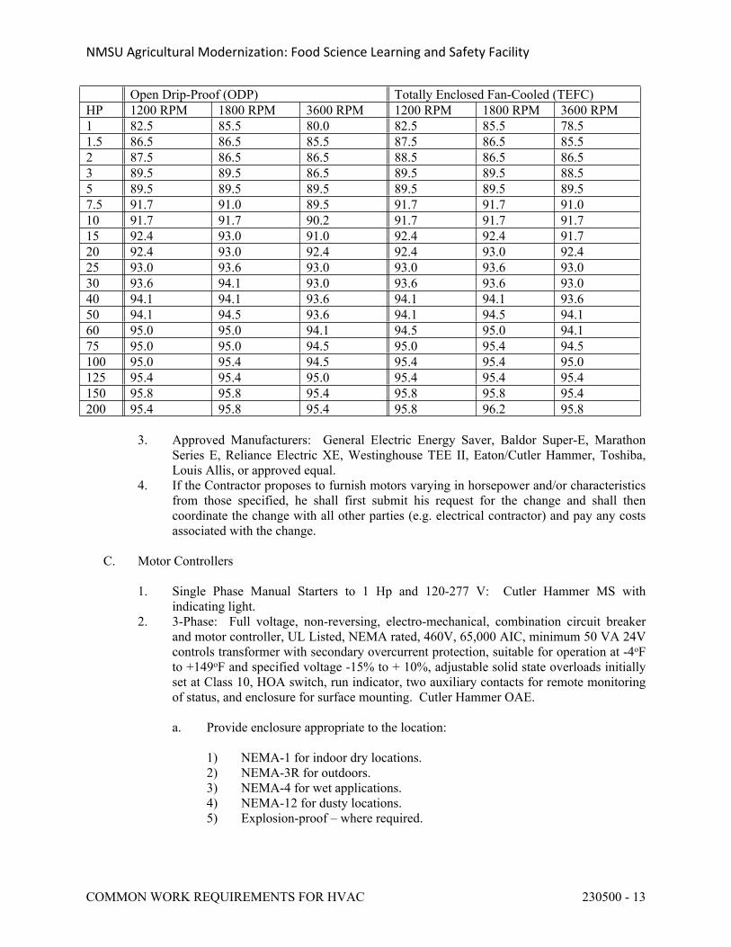
NMSU Agricultural Modernization: Food Science Learning and Safety Facility
COMMON WORK REQUIREMENTS FOR HVAC 230500 - 13
Open Drip-Proof (ODP) Totally Enclosed Fan-Cooled (TEFC)HP 1200 RPM 1800 RPM 3600 RPM 1200 RPM 1800 RPM 3600 RPM1 82.5 85.5 80.0 82.5 85.5 78.51.5 86.5 86.5 85.5 87.5 86.5 85.52 87.5 86.5 86.5 88.5 86.5 86.53 89.5 89.5 86.5 89.5 89.5 88.55 89.5 89.5 89.5 89.5 89.5 89.57.5 91.7 91.0 89.5 91.7 91.7 91.010 91.7 91.7 90.2 91.7 91.7 91.715 92.4 93.0 91.0 92.4 92.4 91.720 92.4 93.0 92.4 92.4 93.0 92.425 93.0 93.6 93.0 93.0 93.6 93.030 93.6 94.1 93.0 93.6 93.6 93.040 94.1 94.1 93.6 94.1 94.1 93.650 94.1 94.5 93.6 94.1 94.5 94.160 95.0 95.0 94.1 94.5 95.0 94.175 95.0 95.0 94.5 95.0 95.4 94.5100 95.0 95.4 94.5 95.4 95.4 95.0125 95.4 95.4 95.0 95.4 95.4 95.4150 95.8 95.8 95.4 95.8 95.8 95.4200 95.4 95.8 95.4 95.8 96.2 95.8
3. Approved Manufacturers: General Electric Energy Saver, Baldor Super-E, Marathon Series E, Reliance Electric XE, Westinghouse TEE II, Eaton/Cutler Hammer, Toshiba, Louis Allis, or approved equal.
4. If the Contractor proposes to furnish motors varying in horsepower and/or characteristics from those specified, he shall first submit his request for the change and shall then coordinate the change with all other parties (e.g. electrical contractor) and pay any costs associated with the change.
C. Motor Controllers 1. Single Phase Manual Starters to 1 Hp and 120-277 V: Cutler Hammer MS with
indicating light.2. 3-Phase: Full voltage, non-reversing, electro-mechanical, combination circuit breaker
and motor controller, UL Listed, NEMA rated, 460V, 65,000 AIC, minimum 50 VA 24V controls transformer with secondary overcurrent protection, suitable for operation at -4oF to +149oF and specified voltage -15% to + 10%, adjustable solid state overloads initially set at Class 10, HOA switch, run indicator, two auxiliary contacts for remote monitoring of status, and enclosure for surface mounting. Cutler Hammer OAE.
a. Provide enclosure appropriate to the location:
1) NEMA-1 for indoor dry locations.2) NEMA-3R for outdoors. 3) NEMA-4 for wet applications.4) NEMA-12 for dusty locations.5) Explosion-proof – where required.
NMSU Agricultural Modernization: Food Science Learning and Safety Facility
COMMON WORK REQUIREMENTS FOR HVAC 230500 - 14
b. Motor controllers factory mounted and wired on AC units, boilers, etc, may be definite purpose, and need not have all the features specified here.
2.3 ELECTRICAL WIRING AND CONTROL EQUIPMENT
A. Provide wiring and conduit as scheduled in Section 23 0549.
B. Coordinate with all disciplines to ensure that all necessary components of control work are included and fully understood.
2.4 IDENTIFICATION
A. Scope: Identify all equipment, ductwork, valves, piping, and control devices shown on the Drawings, identified in the equipment schedules, and indicated in these Specifications. Provide submittals for products and procedures used for identification.
B. Equipment: For all mechanical equipment supplied or installed under Division 23, provide an
equipment identification tag or stencil unit number onto the equipment. Stencils shall be minimum 3-inch height, dark contrasting color, of a material suitable for the application.
1. For rooftop HVAC equipment, provide a permanently affixed, weather-resistant label to identify the areas served.
C. Valves: Provide each valve with a stamped metal tag secured to the valve. Tag shall indicate the valve number, service and function. Provide two sets of prints of drawings showing floor plan for each floor with all valves accurately located and labeled. Drawings shall be neat and easily readable. Provide a typed valve chart, listing the valve number, size, location, function, normal operating position, for each valve. List valves by system, i.e., domestic cold water, hot water, chilled water, etc. Tags shall be stamped brass 1-1/2" diameter, and secured to valves by heavy copper figure eight hooks, braided stainless steel wire anchor, or other approved means.
D. Ductwork: Identify ductwork at or near the fan with stenciled signs on insulated ductwork or engraved laminated plastic signs secured by rustproof screws on un-insulated ductwork. Sign shall identify air conditioning system or fan unit and area served.
E. Piping
1. Provide color-coded pipe labels indicating the service of the pipe and the direction of flow. Piping labels shall comply with ANSI Standard A13.1 regarding color coding and size of lettering. The following standardized color code scheme shall be used:
a. Yellow - Hazardous Materials.b. Green - Liquid Materials of Inherently Low Hazard.c. Blue - Gaseous Materials of Inherently Low Hazard.d. Red - Fire Protection Materials.
2. Labels shall be semi-rigid plastic identification markers. Labels shall "span-on" around pipe without the requirement for adhesive or bonding of piping sizes 3/4 inch through 5 inches. Labels for piping 6 inches and larger shall be furnished with spring attachment at
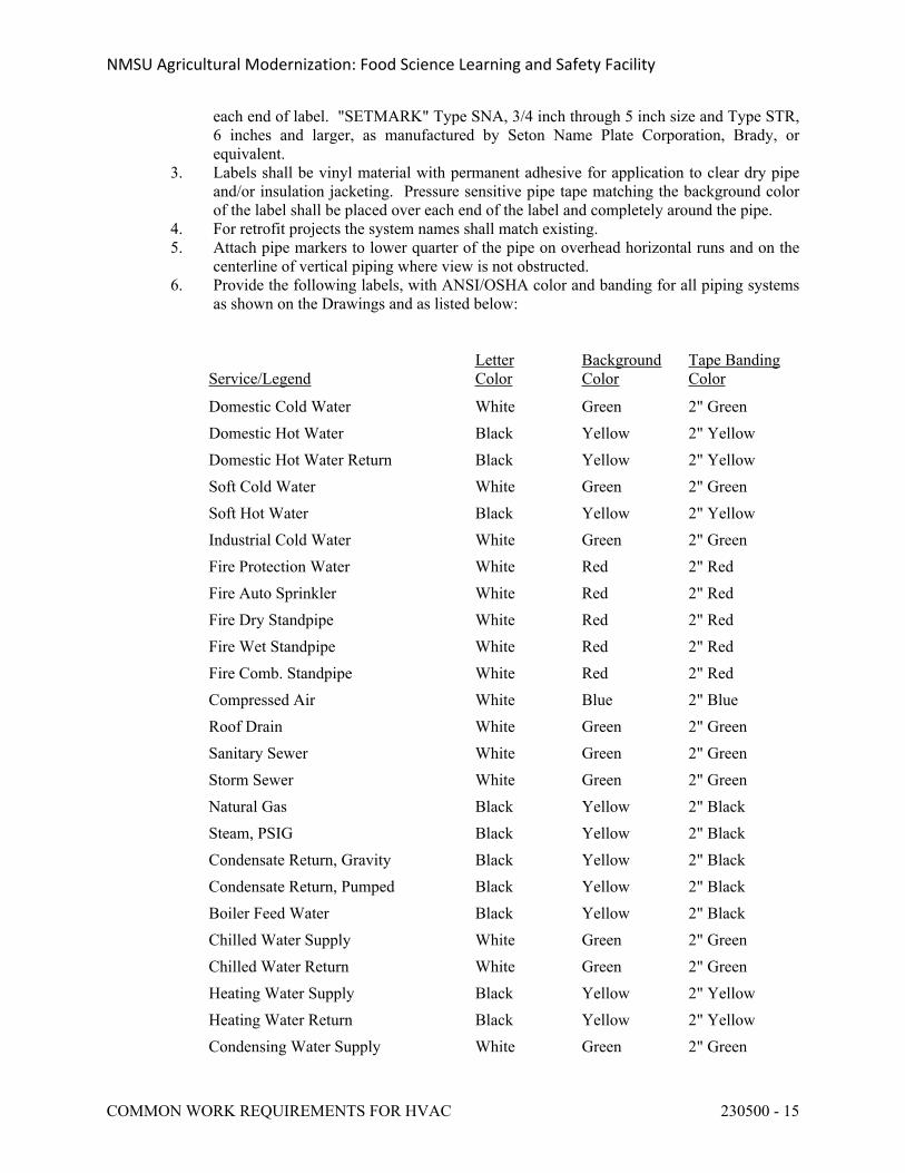
NMSU Agricultural Modernization: Food Science Learning and Safety Facility
COMMON WORK REQUIREMENTS FOR HVAC 230500 - 15
each end of label. "SETMARK" Type SNA, 3/4 inch through 5 inch size and Type STR, 6 inches and larger, as manufactured by Seton Name Plate Corporation, Brady, or equivalent.
3. Labels shall be vinyl material with permanent adhesive for application to clear dry pipe and/or insulation jacketing. Pressure sensitive pipe tape matching the background color of the label shall be placed over each end of the label and completely around the pipe.
4. For retrofit projects the system names shall match existing.5. Attach pipe markers to lower quarter of the pipe on overhead horizontal runs and on the
centerline of vertical piping where view is not obstructed. 6. Provide the following labels, with ANSI/OSHA color and banding for all piping systems
as shown on the Drawings and as listed below:
Service/LegendLetterColor
BackgroundColor
Tape BandingColor
Domestic Cold Water White Green 2" GreenDomestic Hot Water Black Yellow 2" Yellow Domestic Hot Water Return Black Yellow 2" Yellow Soft Cold Water White Green 2" Green Soft Hot Water Black Yellow 2" Yellow Industrial Cold Water White Green 2" GreenFire Protection Water White Red 2" RedFire Auto Sprinkler White Red 2" RedFire Dry Standpipe White Red 2" RedFire Wet Standpipe White Red 2" RedFire Comb. Standpipe White Red 2" RedCompressed Air White Blue 2" BlueRoof Drain White Green 2" GreenSanitary Sewer White Green 2" GreenStorm Sewer White Green 2" GreenNatural Gas Black Yellow 2" BlackSteam, PSIG Black Yellow 2" BlackCondensate Return, Gravity Black Yellow 2" BlackCondensate Return, Pumped Black Yellow 2" BlackBoiler Feed Water Black Yellow 2" BlackChilled Water Supply White Green 2" GreenChilled Water Return White Green 2" GreenHeating Water Supply Black Yellow 2" YellowHeating Water Return Black Yellow 2" YellowCondensing Water Supply White Green 2" Green
NMSU Agricultural Modernization: Food Science Learning and Safety Facility
COMMON WORK REQUIREMENTS FOR HVAC 230500 - 16
Service/LegendLetterColor
BackgroundColor
Tape BandingColor
Condensing Water Return White Green 2" Green
7. Locations: Label pipes at the following points on each piping system:
a. Adjacent to each valve in piping system.b. At every point of entry and exit where piping passes through a wall.c. On each pipe riser and junction.d. At a maximum interval of 20 feet on pipe lines exposed and concealed above
accessible ceilings.e. Adjacent to all special fittings (regulating valves, etc.) in piping systems.f. At every access door.
8. Underground Piping: Provide a continuous, preprinted, bright colored, plastic ribbon cable marker with each underground pipe regardless of whether encased. Locate directly over buried pipe, 6 inches to 8 inches below finished grade. Marker tape used in conjunction with buried plastic piping systems shall be special detector type.
F. Control System Devices: All automatic controls, control panels, zone valves, pressure electric, electric pressure switches, relays and starters shall be clearly tagged and identified. Wording shall be identical to that on the control diagram in the Contract Drawings.
2.5 GENERAL CONSTRUCTION COMPONENTS
A. Roof Curbs and Equipment Support Rails
1. General: Factory fabricated, minimum 12-inch high, galvanized steel, configured to account for roof pitch where pitch exceeds 1/4-inch/ft or where required by manufacturer of supported equipment. Coordinate with roofer and provide cant and step if needed to match roof construction. Actual curb heights to be coordinated by contractor with roofing insulation height to maintain code-required height above final roofing elevation.
2. Roof Curbs: 1.5-inch fiberglass insulation with nominal 2" x 2" wood nailer. Provide damper tray where a damper is indicated. Thycurb TC, Greenheck, RPS, OAE.
3. Equipment Support Rails: Nominal 2" x 4" wood nailer. Thycurb TEMS, Greenheck, RPS, OAE.
B. Access Doors (ADs)
1. Steel frame and door, surface mounted, factory primed, 150o opening, flush, screw-driver operated cam lock, minimum 24” x 24” except as approved, but larger where required for proper access. Where ADs are installed in general construction with a pattern, match AD dimensions to this pattern. Milcor, Krueger, OAE.
a. Sheet Rock Wall or Ceiling: With drywall bead on frame, Milcor Style DW.b. Plaster Wall or Ceiling: Milcor Style K.c. Masonry Walls: Milcor Style M.d. 1-hr and 2-hr rated walls: UL Listed for 1.5-hr Class B Fire Rating, self-closing
and self-latching. Milcor Style UFR.
NMSU Agricultural Modernization: Food Science Learning and Safety Facility
COMMON WORK REQUIREMENTS FOR HVAC 230500 - 17
e. Suspended Ceilings: Milcor Style AT.f. Fire Rated Suspended Ceilings: Milcor Style ATR.
C. Painting: Finish painting of mechanical systems and equipment will be under Spec Section 09 9100, “Painting," unless equipment is specified to be provided with factory-applied finish coats.
2.6 MISCELLANEOUS PROVISIONS
A. Flow Diagrams: Provide half-size prints of each system flow diagram, including air handling, steam, chilled water, heating water, domestic water, domestic HW, etc. Mount framed under plexiglass, and locate either on the associated AHU or on a nearby wall. Incorporate any as-built revisions.
PART 3 - EXECUTION
3.1 INSTALLATION GENERAL REQUIRMENTS
A. Cooperation with Other Trades: Refer to other parts of these Specifications covering the work of other trades which must be carried on in conjunction with the mechanical work so that the construction operations can proceed without harm to the Owner from interference, delay, or absence of coordination. Be responsible for the size and location of all openings, foundations, etc.
B. Trenching and Backfilling: Provide all excavation, trenching and backfilling required for the installation of the work of this division.
C. Manufacturer's Instructions: Install all products in accordance with manufacturers’ recommendations and the requirements of any applicable listings. If manufacturers’ recommendations and/or requirements of applicable listings conflict with plans and specifications, report such conflicts to the Owner's Representative.
D. Field Measurements: Verify all dimensions and conditions governing the work. Examine adjoining work on which the work of this Division is dependent, and report any deficiencies.
E. Do not compromise the building structural, fire resistant construction or vapor barrier system.
F. Supports for Equipment and Systems: Foundations and structural supports for equipment will generally be provided by others. The contractor for this division shall provide supplementary supports as required to support equipment, distribution systems, and other components installed under this division. Prior to installing mechanical work, examine foundations and supports to ensure they are adequate to properly support the equipment. Provide all necessary foundations, structures, supports, inserts, sleeves, etc, for installation of mechanical and plumbing equipment, ductwork and piping, etc. Coordinate installation of such devices with all disciplines. Verify that the devices and supports are adequate as intended and do not overload the building structure.
G. Concealed or Buried Work: For work which is underground or which will be concealed by building construction, provide digital photographs to document the installation throughout the
NMSU Agricultural Modernization: Food Science Learning and Safety Facility
COMMON WORK REQUIREMENTS FOR HVAC 230500 - 18
construction project, but not less than weekly. Include plans indicating where the photographs were taken. Notify the OR of when the work will be complete and provide OR a minimum five-day period to inspect the work after completion but prior to when it is backfilled or concealed by building construction.
H. Access Doors: Provide as required for access to valves, dampers, controls, or other items for which access is required for either operation or servicing. The type of access door shall be as required by the room finish schedule.
I. Alignment of Flexible Couplings: Flexible couplings between motors and driven equipment shall be aligned by a qualified service technician after the equipment is installed and ready for operation. Align equipment per manufacturer’s recommendations under operating conditions and temperature. Provide written certification that each device has been so aligned.
J. Lubrication: Provide all oil for the operation of all equipment until acceptance. Be responsible for all damage to bearings while the equipment is being operated by Contractor up to the date of acceptance of the equipment. Protect all bearings and shafts during installation and thoroughly grease shafts to prevent corrosion. Bearings for items of mechanical equipment shall be marked at each bearing location as to whether the bearing is a sealed type or relubricable type unit.
K. Tests: All tests shall be conducted in the presence of the designated and authorized Owner's Representative. Notify the Owner's one week in advance of all tests. Requirements for testing are specified under the sections covering the various systems. Provide all necessary equipment, materials, and labor to perform the required tests.
L. Protection of Material and Equipment:
1. Protect all work, materials and equipment furnished and installed under Division 23, whether incorporated in the building or not.
2. All items of mechanical equipment shall be stored in a protected weatherproof enclosure prior to installation within the building, or shall be otherwise protected from the weather in a suitable manner as approved.
3. Protect all work and be responsible for all damage done to property, equipment and materials. Coordinate material storage with the Owner's Representative.
4. Pipe and duct openings shall be closed with caps or plugs, or covered to prevent lodgment of dirt or trash during the course of installation. Plumbing fixtures shall not be used by the construction forces. At the completion of the work clean and polish fixtures, equipment and materials prior to turning them over to the Owner.
M. Systems Commissioning: A commissioning Agent will participate in the construction phase of the project.
3.2 DRAWINGS
A. The drawings show the general arrangement of the piping, ductwork, equipment, etc. Follow them as closely as actual building construction and work of other trades will permit. Where discrepancies occur between Plans and Specifications, the more stringent shall govern. All Contract Documents shall be considered as part of the work. Because of the small scale of the drawings, it is not possible to indicate all offsets, fittings and accessories, which may be required, and no attempt has been made to do so. Rather, the drawings convey the general
NMSU Agricultural Modernization: Food Science Learning and Safety Facility
COMMON WORK REQUIREMENTS FOR HVAC 230500 - 19
design intent. Investigate the structural and finish conditions affecting the work and arrange the work accordingly, providing fittings, valves, and accessories as required to meet such conditions. Show any such changes on the Record Drawings.
B. Should any doubt or question arise in respect to the true meaning of the drawings or specifications, submit an RFI.
C. Install equipment, piping, ductwork, and electrical systems with proper clearance for operation,
service, and maintenance, including minimum clearances required by applicable codes, manufacturer's installation instructions, etc. Include proper clearance in front of and above electrical equipment as defined by the National Electric Code (NEC). Piping and ductwork systems shall not be routed through or above electrical equipment rooms, telecommunications rooms, elevator machine rooms, or electrical equipment spaces within mechanical equipment rooms.
D. The unique design features of this project will necessitate that the contractor for this division provide greater than normal levels of coordination and cooperation with other disciplines.
E. Arrange all concealed mechanical systems carefully to fit within the available space without interference with adjacent structural and electrical systems. Make all necessary provisions for penetrations of piping and ductwork, including sleeves and blockouts in structural systems. The exact location of all exposed mechanical systems, including grilles, registers, and diffusers; access doors; sprinkler heads; piping and ductwork exposed within finished areas; and other equipment and devices as applicable, shall be coordinated with the Architect, who shall have final authority for the acceptance of the work as it relates to the aesthetic design for the facility.
3.3 EQUIPMENT SUPPLIED BY OTHERS
A. Certain items of mechanical equipment as listed on the Drawings and/or Specifications will be furnished under other sections of this Specification for mechanical rough-in and connection under Division 23, including plumbing, domestic water and waste, process cooling water, compressed air, exhaust, etc.. All required mechanical services, including connection of such services to equipment shall be provided under Division 23.
3.4 INTERRUPTING SERVICES
A. Coordinate the installation of all work within the building in order to minimize interference with the operation of existing building mechanical, plumbing, fire protection, and utility systems during construction. Connections to existing systems requiring the interruption of service within the building shall be carefully coordinated with the Owner to minimize system downtimes. Requests for the interruption of existing services shall be submitted in writing a minimum of two weeks before the scheduled date. Absolutely no interruption of the existing services will be permitted without written review and authorization.
3.5 CONCRETE BASES AND HOUSEKEEPING PADS
A. Concrete bases and housekeeping pads shall be installed under all pieces of mechanical equipment unless specifically deleted by the Specifications or Drawings.
NMSU Agricultural Modernization: Food Science Learning and Safety Facility
COMMON WORK REQUIREMENTS FOR HVAC 230500 - 20
B. Be responsible for the accurate dimensions of all pads and bases and furnish and install all vibration isolators, anchor bolts, etc.
C. Provide concrete housekeeping pad foundations for all floor mounted equipment installed under this section unless otherwise shown on the Drawings. All concrete bases and housekeeping pads shall conform to the requirements specified under Division 3, Concrete, portions of these Specifications. Pad foundations shall be 4 inches high minimum, unless otherwise indicated on the Drawings. Chamfer edges shall be 1 inch. Faces shall be free of voids and rubbed smooth with carborundum block after stripping forms. Tops shall be level. Provide dowel rods in floor for lateral stability and anchorage.
D. Equipment anchor bolts shall be set in a galvanized pipe or sheet metal sleeves 1 inch larger than bolt diameter. Anchor bolts shall be high strength steel J-shape. Anchor bolt design shall be arranged and paid for by the Contractor.
E. Machinery bases, bed plates, sole plates, or vibration isolation units shall be carefully aligned, shimmed, leveled, and then grouted in place with commercial non-shrink grout. When a flexible coupling is employed as a part of the drive train, the coupling shall be aligned before the machinery base is grouted.
3.6 PRESSURE RELIEF DEVICES
A. Refrigerant pressure relief devices and fusible plugs shall be installed with piping to a safe location in accordance with ANSI/ASHRAE Standard 15. Discharge shall be to atmosphere at a location not less than 15 feet above the adjoining ground level and not less than 20 feet from any window, ventilation opening, or exit from any building. Discharge line sizing shall conform to ANSI/ASHRAE Standard 15-1994.
B. Each discharge pipe shall be equipped with a drip leg capable of holding 1 gallon of liquid. The drip leg shall include a manual drain valve.
3.7 INSTALLATION CHECK
A. An experienced, competent, and authorized representative of the equipment listed below shall visit the site of the work and inspect, check, adjust if necessary, and approve the installation for the equipment listed below. The equipment supplier's representative shall revisit the job site as often as necessary until all trouble is corrected and the equipment installation and operation is approved and accepted.
B. Each equipment supplier's representative shall furnish a written report certifying that the equipment (1) has been properly installed and lubricated; (2) is in accurate alignment; (3) is free from any undue stress imposed by connecting piping or anchor bolts; and, (4) has been operated under full load conditions and that it has operated satisfactorily.
C. Equipment requiring installation check includes the following:
DX Condensing UnitsPumps
NMSU Agricultural Modernization: Food Science Learning and Safety Facility
COMMON WORK REQUIREMENTS FOR HVAC 230500 - 21
Heat ExchangersWater SoftenerDomestic Hot Water HeatersSteam Pressure Reducing StationsSteam Condensate PumpAir Handling UnitsFansHumidifiersFacility Management System (See Division 25)
3.8 OPERATION PRIOR TO ACCEPTANCE
A. Operation of equipment and systems for the benefit of the Owner prior to substantial completion will be allowed provided that a written agreement between the Owner and the Contractor has established warranty and other responsibilities to the satisfaction of both parties.
B. Operation of equipment and systems for the benefit of the Contractor, except for the purposes of testing and balancing, will not be permitted without a written agreement between the Owner and the Contractor establishing warranty and other responsibilities.
3.9 OPERATION AND MAINTENANCE (O&M) INSTRUCTIONS
A. At completion of the project provide two complete bound sets of the following documents, along with two CDs containing searchable PDFs of these documents. Organize bound information in a logical fashion with a table of contents and tabs for the different sections. Organize PDFs in a logical fashion with bookmarks to assist the operating personnel in retrieving desired data. Provide minimum two 1-hour sessions to instruct Owner's facility personnel in how to find information in the bound O&Ms and the PDFs. Take attendance and submit the attendance list to the Owner's Representative. Include the following:
1. Approved Submittals.2. Test reports.3. O&M manuals and instructions covering all equipment supplied under this Division, with
all non-applicable information crossed out. Clearly identify all required routine maintenance. Include parts lists.
4. A master Lubrication Chart listing each piece of equipment, the recommended oil or grease, and the recommended frequency of lubrication.
5. The names and addresses of at least one service agency capable of providing required maintenance for each item of equipment supplied.
6. Complete temperature control diagrams including control descriptions, system sequence of operation, operating instructions, control system maintenance and calibration information, wiring diagrams, and all control setpoints. See Section 23 0900 for additional requirements.
B. See Division 1 for additional requirements concerning manuals, manual distribution, and maintenance materials.
NMSU Agricultural Modernization: Food Science Learning and Safety Facility
COMMON WORK REQUIREMENTS FOR HVAC 230500 - 22
C. Submit O&M manuals for review and distribution to the Owner not less than two weeks prior to the date scheduled for O&M instructions as specified.
D. Demonstrate proper system operation to the owner's operating staff. Provide the services of the contractor and subcontractors (e.g., mechanical, T&B, temperature control, etc), as required to properly demonstrate system operation.
E. Provide the necessary skilled labor and helpers to operate the mechanical systems and equipment for a period of 5 days of eight hours each. During this period, instruct the owner’s facility staff fully in the operations, adjustment and maintenance of all equipment provided. Provide at least two weeks advanced notice, with a written schedule of each training session, the subject of the session, the Contractors' Representatives who plan to attend the session, and the time for each session. Take attendance and submit attendance sheets to the Owner's Representative.
F. Film the instruction and training sessions submit two copies of the DVD.
3.10 RECORD DRAWINGS
A. See Division 1, for additional requirements associated with Project Record Drawings.
B. Maintain a full-size set of marked-up prints showing the installed location and arrangement of all work under this division, and in particular where changes were made during construction. Keep record drawings accurate and up-to-date throughout the construction period. Owner’s Agents may request to review record drawings during construction and in conjunction with review and approval of monthly pay requests. Include copies of all addenda, RFIs, bulletins, and change orders neatly taped or attached to record drawing set. At the completion of the project send the Engineer full-size plans clearly showing all changes from the original design marked up in red so as to facilitate the Engineer incorporating these changes into the Engineer’s CADD files. Forward record drawings to the Owner's Representative prior to submitting a request for substantial completion.
3.11 SITE VISITS AND OBSERVATION OF CONSTRUCTION
A. The Engineer may make periodic visits to the project site at various stages of construction in order to observe the progress and quality of various aspects of the work so as to determine if such work is proceeding in general accordance with the Contract Documents. This observation will not release the Contractor from his responsibility to supervise, direct, and control all construction work and activities. The Engineer has no authority over, or responsibility for means, methods, techniques, sequences, or procedures of construction or for safety precautions and programs, or for failure of the Contractor to comply with applicable laws, regulations, or codes.
B. Prior to substantial completion, request that the Engineer provide a final observation visit. Complete the attached "Final Observation Checklist," and include it with this request. For any items that are not applicable, mark them "N/A."
NMSU Agricultural Modernization: Food Science Learning and Safety Facility
COMMON WORK REQUIREMENTS FOR HVAC 230500 - 23
3.12 PROJECT CLOSEOUT
A. Submit written certification that all work complies with the specifications and applicable codes. Submit certifications and acceptance certificates including proof of delivery of record drawings, O&M manuals, spare parts required, and equipment warranties.
END OF SECTION 230500
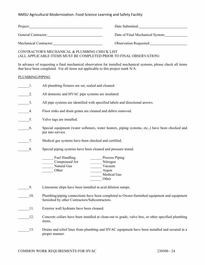
NMSU Agricultural Modernization: Food Science Learning and Safety Facility
COMMON WORK REQUIREMENTS FOR HVAC 230500 - 24
Project: Date Submitted:
General Contractor: Date of Final Mechanical System:
Mechanical Contractor: Observation Requested:
CONTRACTOR'S MECHANICAL & PLUMBING CHECK LIST(ALL APPLICABLE ITEMS MUST BE COMPLETED PRIOR TO FINAL OBSERVATION)
In advance of requesting a final mechanical observation for installed mechanical systems, please check all items that have been completed. For all items not applicable to this project mark N/A.
PLUMBING/PIPING
______1. All plumbing fixtures are set, sealed and cleaned.
______2. All domestic and HVAC pipe systems are insulated.
______3. All pipe systems are identified with specified labels and directional arrows.
______4. Floor sinks and drain grates are cleaned and debris removed.
______5. Valve tags are installed.
______6. Special equipment (water softeners, water heaters, piping systems, etc.,) have been checked and put into service.
______7. Medical gas systems have been checked and certified.
______8. Special piping systems have been cleaned and pressure tested.
______ Fuel Handling ______ Process Piping______ Compressed Air ______ Nitrogen______ Natural Gas ______ Vacuum______ Other ______ Argon
______ Medical Gas______ Other
______9. Limestone chips have been installed in acid dilution sumps.
______10. Plumbing/piping connections have been completed to Owner-furnished equipment and equipment furnished by other Contractors/Subcontractors.
______11. Exterior wall hydrants have been cleaned.
______12. Concrete collars have been installed at clean-out to grade, valve box, or other specified plumbing items.
______13. Drains and relief lines from plumbing and HVAC equipment have been installed and secured in a proper manner.
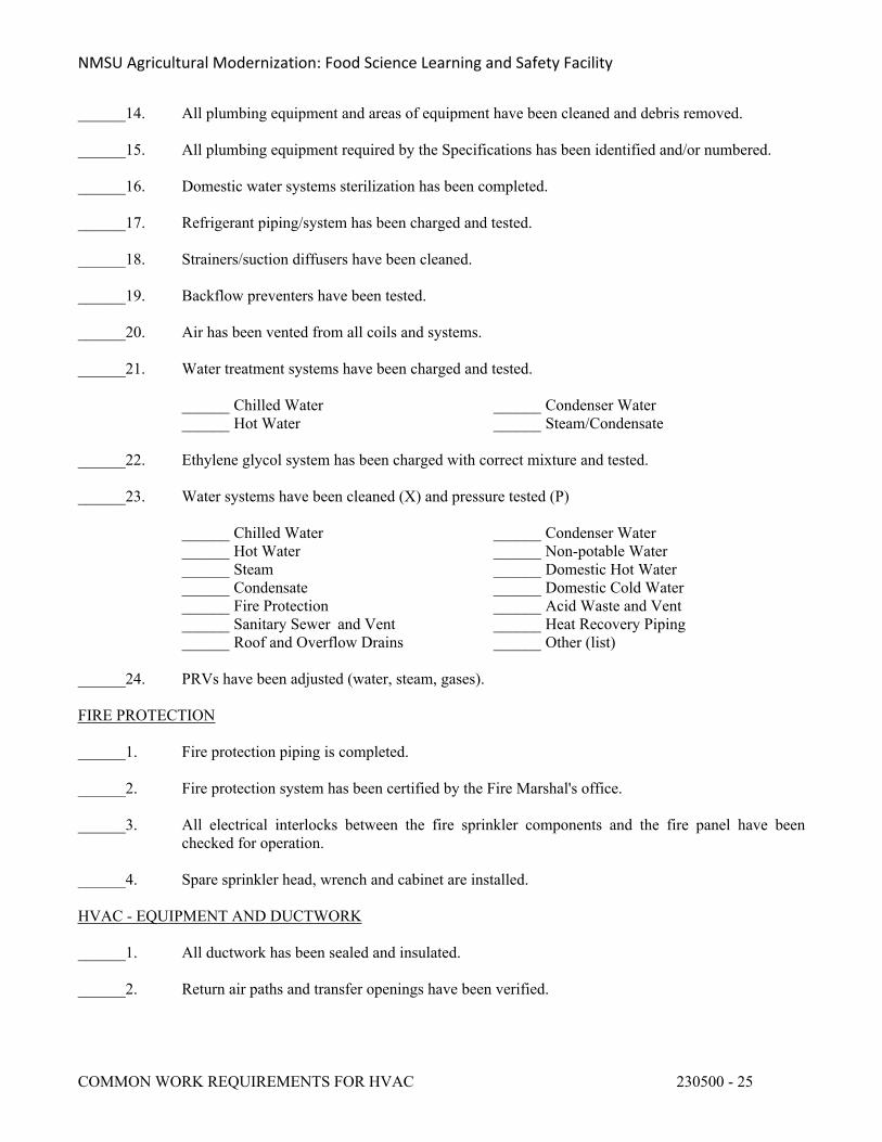
NMSU Agricultural Modernization: Food Science Learning and Safety Facility
COMMON WORK REQUIREMENTS FOR HVAC 230500 - 25
______14. All plumbing equipment and areas of equipment have been cleaned and debris removed.
______15. All plumbing equipment required by the Specifications has been identified and/or numbered.
______16. Domestic water systems sterilization has been completed.
______17. Refrigerant piping/system has been charged and tested.
______18. Strainers/suction diffusers have been cleaned.
______19. Backflow preventers have been tested.
______20. Air has been vented from all coils and systems.
______21. Water treatment systems have been charged and tested.
______ Chilled Water ______ Condenser Water______ Hot Water ______ Steam/Condensate
______22. Ethylene glycol system has been charged with correct mixture and tested.
______23. Water systems have been cleaned (X) and pressure tested (P)
______ Chilled Water ______ Condenser Water______ Hot Water ______ Non-potable Water______ Steam ______ Domestic Hot Water______ Condensate ______ Domestic Cold Water______ Fire Protection ______ Acid Waste and Vent______ Sanitary Sewer and Vent ______ Heat Recovery Piping______ Roof and Overflow Drains ______ Other (list)
______24. PRVs have been adjusted (water, steam, gases).
FIRE PROTECTION
______1. Fire protection piping is completed.
______2. Fire protection system has been certified by the Fire Marshal's office.
______3. All electrical interlocks between the fire sprinkler components and the fire panel have been checked for operation.
______4. Spare sprinkler head, wrench and cabinet are installed.
HVAC - EQUIPMENT AND DUCTWORK
______1. All ductwork has been sealed and insulated.
______2. Return air paths and transfer openings have been verified.
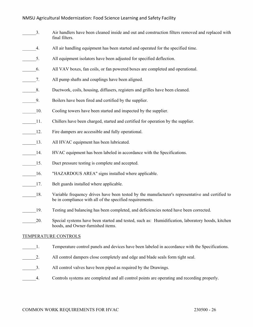
NMSU Agricultural Modernization: Food Science Learning and Safety Facility
COMMON WORK REQUIREMENTS FOR HVAC 230500 - 26
______3. Air handlers have been cleaned inside and out and construction filters removed and replaced with final filters.
______4. All air handling equipment has been started and operated for the specified time.
______5. All equipment isolators have been adjusted for specified deflection.
______6. All VAV boxes, fan coils, or fan powered boxes are completed and operational.
______7. All pump shafts and couplings have been aligned.
______8. Ductwork, coils, housing, diffusers, registers and grilles have been cleaned.
______9. Boilers have been fired and certified by the supplier.
______10. Cooling towers have been started and inspected by the supplier.
______11. Chillers have been charged, started and certified for operation by the supplier.
______12. Fire dampers are accessible and fully operational.
______13. All HVAC equipment has been lubricated.
______14. HVAC equipment has been labeled in accordance with the Specifications.
______15. Duct pressure testing is complete and accepted.
______16. "HAZARDOUS AREA" signs installed where applicable.
______17. Belt guards installed where applicable.
______18. Variable frequency drives have been tested by the manufacturer's representative and certified to be in compliance with all of the specified requirements.
______19. Testing and balancing has been completed, and deficiencies noted have been corrected.
______20. Special systems have been started and tested, such as: Humidification, laboratory hoods, kitchen hoods, and Owner-furnished items.
TEMPERATURE CONTROLS
______1. Temperature control panels and devices have been labeled in accordance with the Specifications.
______2. All control dampers close completely and edge and blade seals form tight seal.
______3. All control valves have been piped as required by the Drawings.
______4. Controls systems are completed and all control points are operating and recording properly.
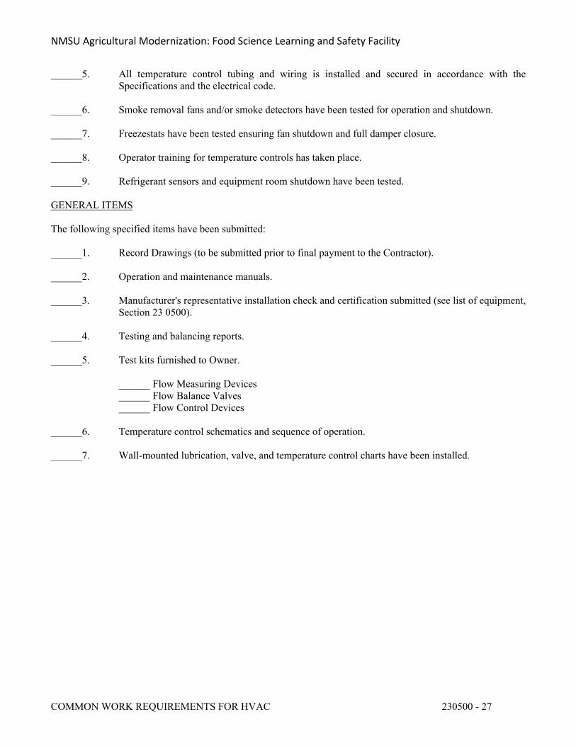
NMSU Agricultural Modernization: Food Science Learning and Safety Facility
COMMON WORK REQUIREMENTS FOR HVAC 230500 - 27
______5. All temperature control tubing and wiring is installed and secured in accordance with the Specifications and the electrical code.
______6. Smoke removal fans and/or smoke detectors have been tested for operation and shutdown.
______7. Freezestats have been tested ensuring fan shutdown and full damper closure.
______8. Operator training for temperature controls has taken place.
______9. Refrigerant sensors and equipment room shutdown have been tested.
GENERAL ITEMS
The following specified items have been submitted:
______1. Record Drawings (to be submitted prior to final payment to the Contractor).
______2. Operation and maintenance manuals.
______3. Manufacturer's representative installation check and certification submitted (see list of equipment, Section 23 0500).
______4. Testing and balancing reports.
______5. Test kits furnished to Owner.
______ Flow Measuring Devices______ Flow Balance Valves______ Flow Control Devices
______6. Temperature control schematics and sequence of operation.
______7. Wall-mounted lubrication, valve, and temperature control charts have been installed.
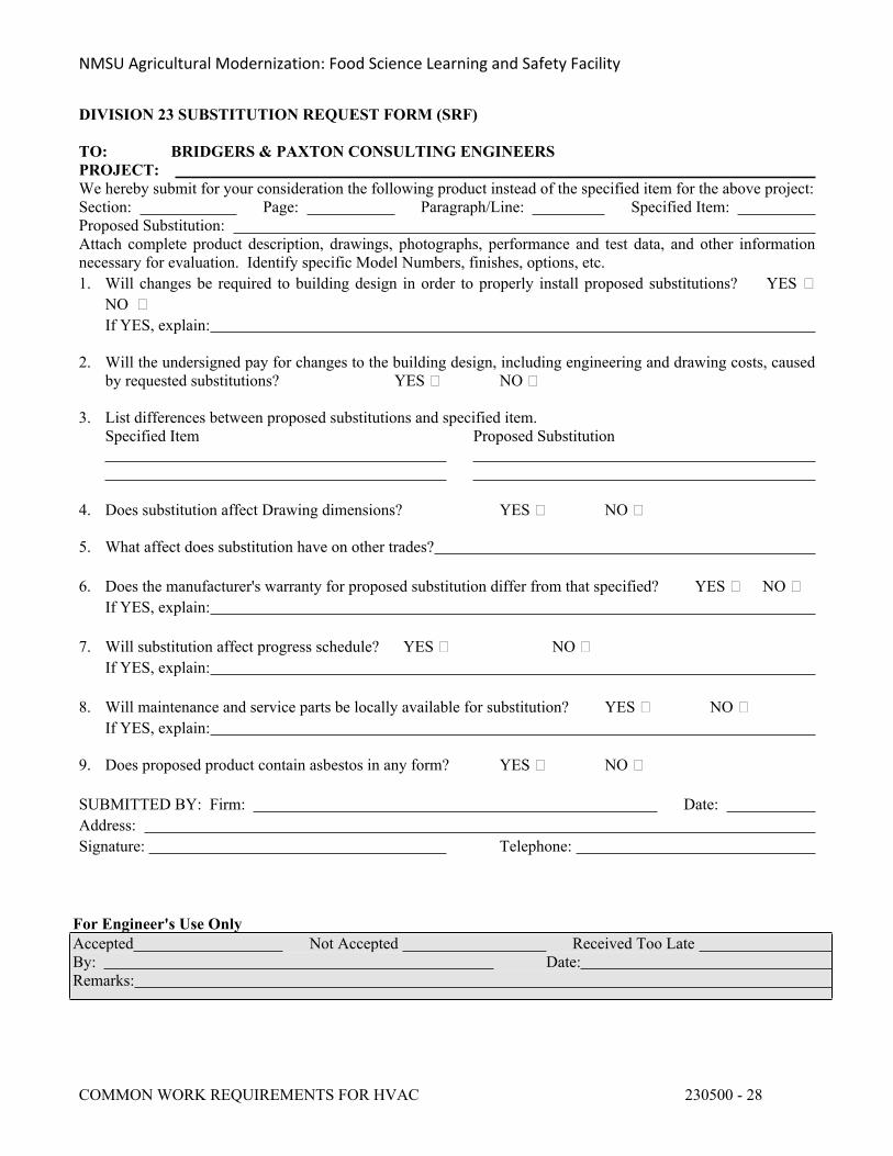
NMSU Agricultural Modernization: Food Science Learning and Safety Facility
COMMON WORK REQUIREMENTS FOR HVAC 230500 - 28
DIVISION 23 SUBSTITUTION REQUEST FORM (SRF)
TO: BRIDGERS & PAXTON CONSULTING ENGINEERSPROJECT: We hereby submit for your consideration the following product instead of the specified item for the above project:Section: Page: Paragraph/Line: Specified Item: Proposed Substitution: Attach complete product description, drawings, photographs, performance and test data, and other information necessary for evaluation. Identify specific Model Numbers, finishes, options, etc.1. Will changes be required to building design in order to properly install proposed substitutions? YES
NO If YES, explain:
2. Will the undersigned pay for changes to the building design, including engineering and drawing costs, caused by requested substitutions? YES NO
3. List differences between proposed substitutions and specified item.Specified Item Proposed Substitution
4. Does substitution affect Drawing dimensions? YES NO
5. What affect does substitution have on other trades?
6. Does the manufacturer's warranty for proposed substitution differ from that specified? YES NO If YES, explain:
7. Will substitution affect progress schedule? YES NO If YES, explain:
8. Will maintenance and service parts be locally available for substitution? YES NO If YES, explain:
9. Does proposed product contain asbestos in any form? YES NO
SUBMITTED BY: Firm: Date: Address: Signature: Telephone:
For Engineer's Use OnlyAccepted Not Accepted Received Too Late By: Date:Remarks:
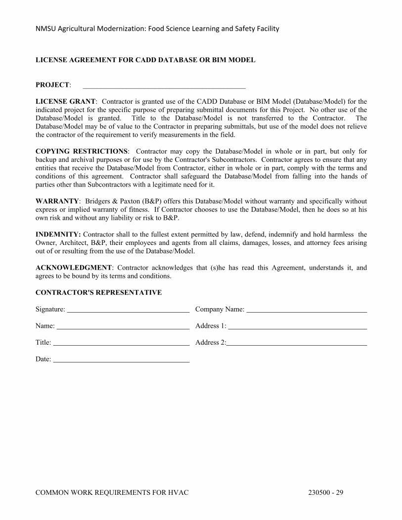
NMSU Agricultural Modernization: Food Science Learning and Safety Facility
COMMON WORK REQUIREMENTS FOR HVAC 230500 - 29
LICENSE AGREEMENT FOR CADD DATABASE OR BIM MODEL
PROJECT: _____________________________________________
LICENSE GRANT: Contractor is granted use of the CADD Database or BIM Model (Database/Model) for the indicated project for the specific purpose of preparing submittal documents for this Project. No other use of the Database/Model is granted. Title to the Database/Model is not transferred to the Contractor. The Database/Model may be of value to the Contractor in preparing submittals, but use of the model does not relieve the contractor of the requirement to verify measurements in the field.
COPYING RESTRICTIONS: Contractor may copy the Database/Model in whole or in part, but only for backup and archival purposes or for use by the Contractor's Subcontractors. Contractor agrees to ensure that any entities that receive the Database/Model from Contractor, either in whole or in part, comply with the terms and conditions of this agreement. Contractor shall safeguard the Database/Model from falling into the hands of parties other than Subcontractors with a legitimate need for it.
WARRANTY: Bridgers & Paxton (B&P) offers this Database/Model without warranty and specifically without express or implied warranty of fitness. If Contractor chooses to use the Database/Model, then he does so at his own risk and without any liability or risk to B&P.
INDEMNITY: Contractor shall to the fullest extent permitted by law, defend, indemnify and hold harmless the Owner, Architect, B&P, their employees and agents from all claims, damages, losses, and attorney fees arising out of or resulting from the use of the Database/Model.
ACKNOWLEDGMENT: Contractor acknowledges that (s)he has read this Agreement, understands it, and agrees to be bound by its terms and conditions.
CONTRACTOR'S REPRESENTATIVE
Signature: Company Name:
Name: Address 1:
Title: Address 2:
Date:
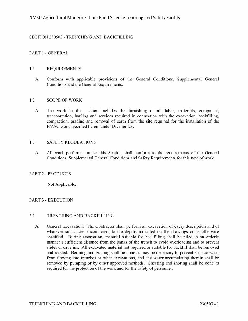
NMSU Agricultural Modernization: Food Science Learning and Safety Facility
TRENCHING AND BACKFILLING 230503 - 1
SECTION 230503 - TRENCHING AND BACKFILLING
PART 1 - GENERAL
1.1 REQUIREMENTS
A. Conform with applicable provisions of the General Conditions, Supplemental General Conditions and the General Requirements.
1.2 SCOPE OF WORK
A. The work in this section includes the furnishing of all labor, materials, equipment, transportation, hauling and services required in connection with the excavation, backfilling, compaction, grading and removal of earth from the site required for the installation of the HVAC work specified herein under Division 23.
1.3 SAFETY REGULATIONS
A. All work performed under this Section shall conform to the requirements of the General Conditions, Supplemental General Conditions and Safety Requirements for this type of work.
PART 2 - PRODUCTS
Not Applicable.
PART 3 - EXECUTION
3.1 TRENCHING AND BACKFILLING
A. General Excavation: The Contractor shall perform all excavation of every description and of whatever substances encountered, to the depths indicated on the drawings or as otherwise specified. During excavation, material suitable for backfilling shall be piled in an orderly manner a sufficient distance from the banks of the trench to avoid overloading and to prevent slides or cave-ins. All excavated material not required or suitable for backfill shall be removed and wasted. Berming and grading shall be done as may be necessary to prevent surface water from flowing into trenches or other excavations, and any water accumulating therein shall be removed by pumping or by other approved methods. Sheeting and shoring shall be done as required for the protection of the work and for the safety of personnel.
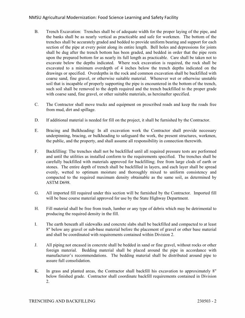
NMSU Agricultural Modernization: Food Science Learning and Safety Facility
TRENCHING AND BACKFILLING 230503 - 2
B. Trench Excavation: Trenches shall be of adequate width for the proper laying of the pipe, and the banks shall be as nearly vertical as practicable and safe for workmen. The bottom of the trenches shall be accurately graded and bedded to provide uniform bearing and support for each section of the pipe at every point along its entire length. Bell holes and depressions for joints shall be dug after the trench bottom has been graded, and bedded in order that the pipe rests upon the prepared bottom for as nearly its full length as practicable. Care shall be taken not to excavate below the depths indicated. Where rock excavation is required, the rock shall be excavated to a minimum overdepth of 4 inches below the trench depths indicated on the drawings or specified. Overdepths in the rock and common excavation shall be backfilled with coarse sand, fine gravel, or otherwise suitable material. Whenever wet or otherwise unstable soil that is incapable of properly supporting the pipe is encountered in the bottom of the trench, such soil shall be removed to the depth required and the trench backfilled to the proper grade with coarse sand, fine gravel, or other suitable materials, as hereinafter specified.
C. The Contractor shall move trucks and equipment on prescribed roads and keep the roads free from mud, dirt and spillage.
D. If additional material is needed for fill on the project, it shall be furnished by the Contractor.
E. Bracing and Bulkheading: In all excavation work the Contractor shall provide necessary underpinning, bracing, or bulkheading to safeguard the work, the present structures, workmen, the public, and the property, and shall assume all responsibility in connection therewith.
F. Backfilling: The trenches shall not be backfilled until all required pressure tests are performed and until the utilities as installed conform to the requirements specified. The trenches shall be carefully backfilled with materials approved for backfilling; free from large clods of earth or stones. The entire depth of trench shall be backfilled in layers, and each layer shall be spread evenly, wetted to optimum moisture and thoroughly mixed to uniform consistency and compacted to the required maximum density obtainable as the same soil, as determined by ASTM D698.
G. All imported fill required under this section will be furnished by the Contractor. Imported fill will be base course material approved for use by the State Highway Department.
H. Fill material shall be free from trash, lumber or any type of debris which may be detrimental to producing the required density in the fill.
I. The earth beneath all sidewalks and concrete slabs shall be backfilled and compacted to at least 8" below any gravel or sub-base material before the placement of gravel or other base material and shall be coordinated with requirements contained within Division 2.
J. All piping not encased in concrete shall be bedded in sand or fine gravel, without rocks or other foreign material. Bedding material shall be placed around the pipe in accordance with manufacturer’s recommendations. The bedding material shall be distributed around pipe to assure full consolidation.
K. In grass and planted areas, the Contractor shall backfill his excavation to approximately 8" below finished grade. Contractor shall coordinate backfill requirements contained in Division 2.
NMSU Agricultural Modernization: Food Science Learning and Safety Facility
TRENCHING AND BACKFILLING 230503 - 3
L. The Contractor shall protect from damage all existing underground utilities and utility tunnels indicated on the Contract Drawings. Any damage to such existing utilities or utility tunnels shall be repaired by the Contractor without additional costs to the Owner.
M. Provide density test for trench, backfill in accordance with Division 2 requirements.
END OF SECTION 230503
NMSU Agricultural Modernization: Food Science Learning and Safety Facility
PIPE AND PIPE FITTINGS 230504 - 1
SECTION 230504 - PIPE AND PIPE FITTINGS
PART 1 - GENERAL
1.1 REQUIREMENTS
A. Conform with applicable provisions of the General Conditions, Supplemental General Conditions and General Requirements.
B. Lead Ban: All systems and system components, pipe, fittings, and fixtures furnished under Division 23 shall be lead free.
1. Any product designed for dispensing potable water shall meet both the NSF 61 and NSF 372 test standards via third-party testing and certification.
2. Lead free refers to <0.25% weighted average lead content in relation to wetted surface of pipe, fittings, and fixtures in systems delivering water for human consumption, and solder and flux which does not contain more than 0.2% lead.
1.2 RELATED SECTIONS
A. Section 23 0500, Common Work Requirements for HVAC.
1.3 SUBMITTAL DATA
A. Contractor shall furnish complete submittal data for all piping materials, including manufacturer's specifications, certifications, class, type and schedule. Submittal data shall additionally be furnished for pipe hangers and supports, pipe sleeves including sealing and fire safing materials and installation.
PART 2 - PRODUCTS
2.1 PIPE AND PIPE FITTINGS
A. Piping system materials shall be furnished as specified under the Sections describing the various piping systems. Pipe fittings shall be compatible with the piping systems in which they are installed.
B. Pipe fittings for steel piping systems shall be weld, or screwed. Butt weld fittings shall be manufactured by Weld-Bend, Laddish, or equivalent, standard or extra strong as specified in the applicable Sections of this Specification, conforming to ANSI Standard B16.9. All 900 weld elbows shall be long radius unless otherwise specified. Wherever tee connections are required in the piping system, manufacturer's straight or reducing tees shall be utilized. The use of fittings formed from welded pipe or pipe sections will not be permitted. Forged steel
NMSU Agricultural Modernization: Food Science Learning and Safety Facility
PIPE AND PIPE FITTINGS 230504 - 2
"Weld-O-Lets", "Branch-O-Lets", and "Thred-O-Lets", as manufactured by Bonney Forge or equivalent, may be utilized for welded branch and tap connections up to one-half the size of the main. Forged steel half-couplings conforming to ANSI B16.11 may be used for drain, vent and gauge connections. Flanges shall be forged steel weld neck or slip-on, raised face, Class 150 or 300 as specified in the applicable Sections of this Specification with full face or ring type non-asbestos gasket material suitable for the application.
C. Socket weld fittings shall be Schedule 40, 2000 pound or Schedule 80, 3000 pound construction, as specified in the applicable Sections of this Specification, conforming to ANSI B16.11, as manufactured by Grinnell or equivalent.
D. Screwed fittings shall be Class 150 standard or Class 300 extra heavy, black or galvanized, malleable iron or cast iron, as specified in the applicable Sections of this Specification, as manufactured by Grinnell or equivalent. Screwed malleable iron fittings shall conform to ANSI B16.3 and cast iron screwed fittings shall conform to ANSI B16.4. Bushing reduction of a single pipe size or use of close nipples will be permitted.
E. Pipe fittings for copper piping system shall be wrought copper conforming to ANSI B16.22. Cast brass fittings conforming to ANSI B16.23, may be utilized for sanitary drainage, waste and vent systems, HVAC gravity condensate drainage system, and other non-pressure applications.
F. Bronze flanges, Class 125 and Class 150, shall conform to ANSI B16.24.
G. Cast iron fittings for cast iron sanitary soil, waste, and venting piping systems shall be as specified in Division 22.
H. Ductile iron fittings for ductile iron water service piping systems shall be as specified in Division 22.
2.2 FLOOR, WALL AND CEILING PLATES
A. Where uncovered, exposed pipes pass through finished floors, finished walls, or finished ceilings, they shall be fitted with chromium plated spun brass escutcheon plates. Plates shall be large enough to completely close the hole around the pipe, and shall be not less than 1-1/2" or more than 2-1/2" larger than the diameter of the pipes. All plates shall be securely held in place.
2.3 UNIONS
A. Piping 2-1/2" and larger shall be provided with bolted flange union connections. Weld flanges and bolting shall conform to ANSI B16.5. Bronze flanges shall conform to ANSI B16.24. Flange class shall be as specified in the applicable Sections of the Specifications.
B. Malleable iron grooved joint unions with brass to iron seats, Class 125, 250, or 300, as required by the application and compatibility requirements with the piping system fitting classification, conforming to MSS SP-77 and ANSI B16.39, shall be provided in piping systems 2" and smaller. Copper unions conforming to ANSI B16.22 shall be provided in copper piping
NMSU Agricultural Modernization: Food Science Learning and Safety Facility
PIPE AND PIPE FITTINGS 230504 - 3
systems. Union connections shall be installed at all coils, control valves, equipment connections, and at other locations shown on the drawings, and required for proper system operation and maintenance.
2.4 DIELECTRIC FITTINGS
A. Dielectric insulating fittings shall be provided to connect dissimilar metals, such as copper tubing to ferrous metal pipe. Connections 2" and smaller shall be threaded dielectric union conforming to ANSI B16.39. Connections 2-1/2" and larger shall be flange union with dielectric gasket and bolt sleeves, conforming to ANSI B16.42. Insulating fittings will not be required between bronze valves and copper piping, unless otherwise specified.
2.5 PIPE HANGERS AND SUPPORTS
A. All piping shall be rigidly supported from the building structure by means of hanger assemblies properly selected and sized for the application in accordance with the manufacturer's recommendations and specifications. Pipe hangers shall be Grinnell, B-Line, Erico, or equivalent.
B. No attempt has been made to show all required piping supports in all locations, either on the drawings or in the details. The absence of pipe supports and details on any drawing shall not relieve the Contractor of the responsibility for furnishing and installing proper hangers and supports throughout.
C. Piping hangers shall be spaced on the scheduled maximum spacing and shall have hangers not more than one foot from each elbow and other changes in direction or elevation. Provide additional hangers and supports at valves, strainers, in-line pumps adjacent to flexible connections, and other required heavy components. Piping system shall be installed in an approved manner and shall not overload the building structural frame. Contractor shall provide additional hangers and miscellaneous steel supports as may be required to distribute the piping system load over multiple structural members where required or directed. Maximum allowable spacing for steel and copper piping, other than fire protection piping, shall be as scheduled in Table No. 1.
TABLE NO. 1
MAXIMUM SUPPORT SPACING FOR STEELAND COPPER PIPING SYSTEMS
Steel Piping - Maximum Spacing
1/2" - 5'-0"3/4" and 1" - 6'-0"1-1/4" through 2" - 8'-0"2-1/2" through 6" - 10'-0"8" through 12" - 12'-0"
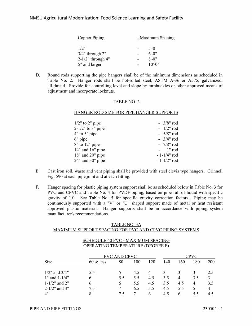
NMSU Agricultural Modernization: Food Science Learning and Safety Facility
PIPE AND PIPE FITTINGS 230504 - 4
Copper Piping - Maximum Spacing
1/2" - 5'-03/4" through 2" - 6'-0"2-1/2" through 4" - 8'-0"5" and larger - 10'-0"
D. Round rods supporting the pipe hangers shall be of the minimum dimensions as scheduled in Table No. 2. Hanger rods shall be hot-rolled steel, ASTM A-36 or A575, galvanized, all-thread. Provide for controlling level and slope by turnbuckles or other approved means of adjustment and incorporate locknuts.
TABLE NO. 2
HANGER ROD SIZE FOR PIPE HANGER SUPPORTS
1/2" to 2" pipe - 3/8" rod2-1/2" to 3" pipe - 1/2" rod4" to 5" pipe - 5/8" rod6" pipe - 3/4" rod8" to 12" pipe - 7/8" rod14" and 16" pipe - 1" rod18" and 20" pipe - 1-1/4" rod24" and 30" pipe - 1-1/2" rod
E. Cast iron soil, waste and vent piping shall be provided with steel clevis type hangers. Grinnell Fig. 590 at each pipe joint and at each fitting.
F. Hanger spacing for plastic piping system support shall be as scheduled below in Table No. 3 for PVC and CPVC and Table No. 4 for PVDF piping, based on pipe full of liquid with specific gravity of 1.0. See Table No. 5 for specific gravity correction factors. Piping may be continuously supported with a "V" or "U" shaped support made of metal or heat resistant approved plastic material. Hanger supports shall be in accordance with piping system manufacturer's recommendations.
TABLE NO. 3AMAXIMUM SUPPORT SPACING FOR PVC AND CPVC PIPING SYSTEMS
SCHEDULE 40 PVC - MAXIMUM SPACINGOPERATING TEMPERATURE (DEGREE F)
PVC AND CPVC CPVC Size 60 & less 80 100 120 140 160 180 200
1/2" and 3/4" 5.5 5 4.5 4 3 3 3 2.51" and 1-1/4" 6 5.5 5.5 4.5 3.5 4 3.5 31-1/2" and 2" 6 6 5.5 4.5 3.5 4.5 4 3.52-1/2" and 3" 7.5 7 6.5 5.5 4.5 5.5 5 44" 8 7.5 7 6 4.5 6 5.5 4.5
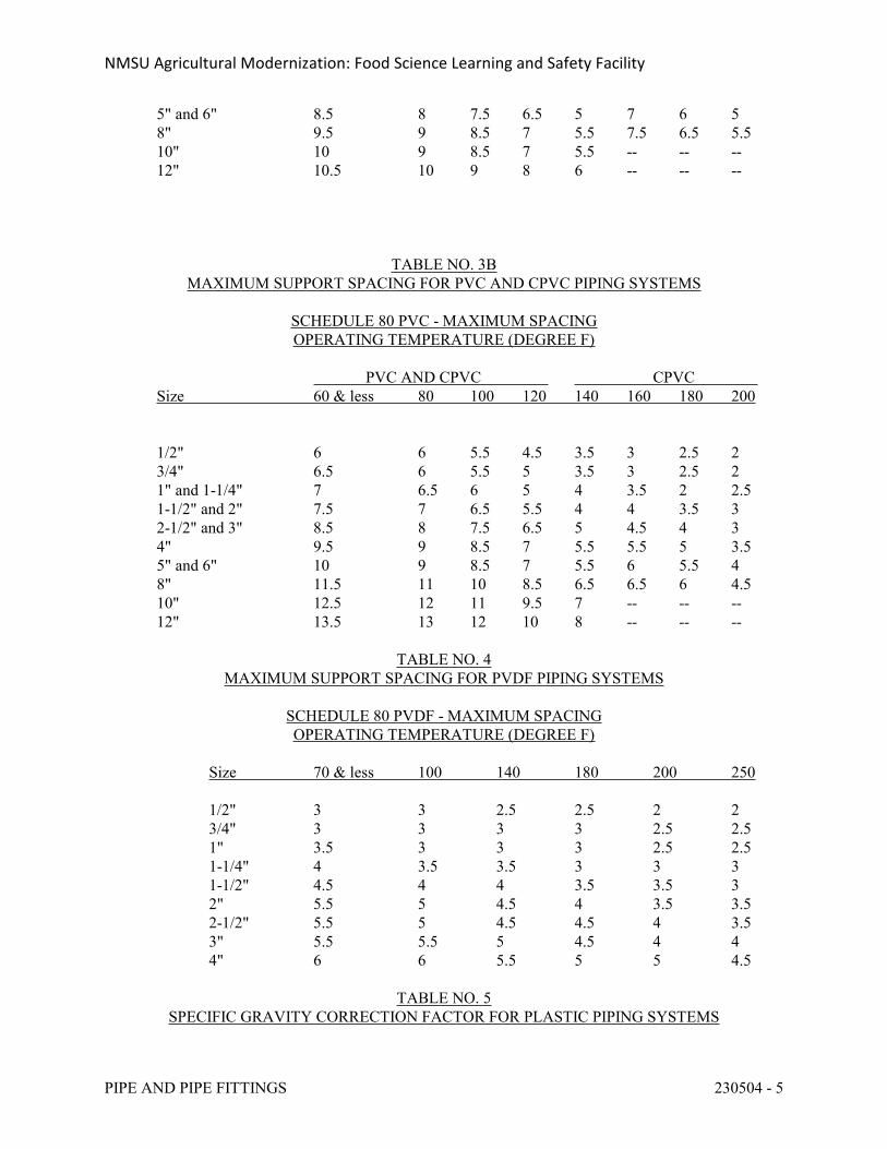
NMSU Agricultural Modernization: Food Science Learning and Safety Facility
PIPE AND PIPE FITTINGS 230504 - 5
5" and 6" 8.5 8 7.5 6.5 5 7 6 58" 9.5 9 8.5 7 5.5 7.5 6.5 5.510" 10 9 8.5 7 5.5 -- -- --12" 10.5 10 9 8 6 -- -- --
TABLE NO. 3BMAXIMUM SUPPORT SPACING FOR PVC AND CPVC PIPING SYSTEMS
SCHEDULE 80 PVC - MAXIMUM SPACINGOPERATING TEMPERATURE (DEGREE F)
PVC AND CPVC CPVC Size 60 & less 80 100 120 140 160 180 200
1/2" 6 6 5.5 4.5 3.5 3 2.5 23/4" 6.5 6 5.5 5 3.5 3 2.5 21" and 1-1/4" 7 6.5 6 5 4 3.5 2 2.51-1/2" and 2" 7.5 7 6.5 5.5 4 4 3.5 32-1/2" and 3" 8.5 8 7.5 6.5 5 4.5 4 34" 9.5 9 8.5 7 5.5 5.5 5 3.55" and 6" 10 9 8.5 7 5.5 6 5.5 48" 11.5 11 10 8.5 6.5 6.5 6 4.510" 12.5 12 11 9.5 7 -- -- --12" 13.5 13 12 10 8 -- -- --
TABLE NO. 4MAXIMUM SUPPORT SPACING FOR PVDF PIPING SYSTEMS
SCHEDULE 80 PVDF - MAXIMUM SPACINGOPERATING TEMPERATURE (DEGREE F)
Size 70 & less 100 140 180 200 250
1/2" 3 3 2.5 2.5 2 23/4" 3 3 3 3 2.5 2.51" 3.5 3 3 3 2.5 2.51-1/4" 4 3.5 3.5 3 3 31-1/2" 4.5 4 4 3.5 3.5 32" 5.5 5 4.5 4 3.5 3.52-1/2" 5.5 5 4.5 4.5 4 3.53" 5.5 5.5 5 4.5 4 44" 6 6 5.5 5 5 4.5
TABLE NO. 5SPECIFIC GRAVITY CORRECTION FACTOR FOR PLASTIC PIPING SYSTEMS
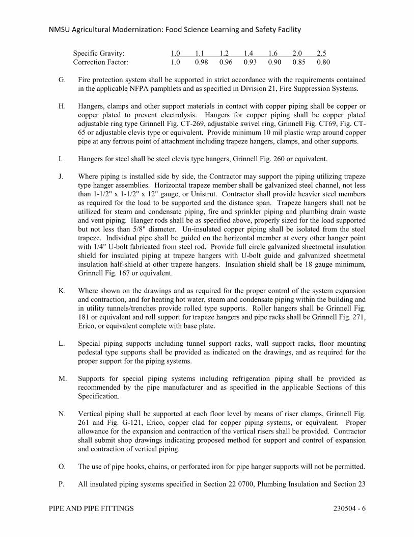
NMSU Agricultural Modernization: Food Science Learning and Safety Facility
PIPE AND PIPE FITTINGS 230504 - 6
Specific Gravity: 1.0 1.1 1.2 1.4 1.6 2.0 2.5Correction Factor: 1.0 0.98 0.96 0.93 0.90 0.85 0.80
G. Fire protection system shall be supported in strict accordance with the requirements contained in the applicable NFPA pamphlets and as specified in Division 21, Fire Suppression Systems.
H. Hangers, clamps and other support materials in contact with copper piping shall be copper or copper plated to prevent electrolysis. Hangers for copper piping shall be copper plated adjustable ring type Grinnell Fig. CT-269, adjustable swivel ring, Grinnell Fig. CT69, Fig. CT-65 or adjustable clevis type or equivalent. Provide minimum 10 mil plastic wrap around copper pipe at any ferrous point of attachment including trapeze hangers, clamps, and other supports.
I. Hangers for steel shall be steel clevis type hangers, Grinnell Fig. 260 or equivalent.
J. Where piping is installed side by side, the Contractor may support the piping utilizing trapeze type hanger assemblies. Horizontal trapeze member shall be galvanized steel channel, not less than 1-1/2" x 1-1/2" x 12" gauge, or Unistrut. Contractor shall provide heavier steel members as required for the load to be supported and the distance span. Trapeze hangers shall not be utilized for steam and condensate piping, fire and sprinkler piping and plumbing drain waste and vent piping. Hanger rods shall be as specified above, properly sized for the load supported but not less than 5/8" diameter. Un-insulated copper piping shall be isolated from the steel trapeze. Individual pipe shall be guided on the horizontal member at every other hanger point with 1/4" U-bolt fabricated from steel rod. Provide full circle galvanized sheetmetal insulation shield for insulated piping at trapeze hangers with U-bolt guide and galvanized sheetmetal insulation half-shield at other trapeze hangers. Insulation shield shall be 18 gauge minimum, Grinnell Fig. 167 or equivalent.
K. Where shown on the drawings and as required for the proper control of the system expansion and contraction, and for heating hot water, steam and condensate piping within the building and in utility tunnels/trenches provide rolled type supports. Roller hangers shall be Grinnell Fig. 181 or equivalent and roll support for trapeze hangers and pipe racks shall be Grinnell Fig. 271, Erico, or equivalent complete with base plate.
L. Special piping supports including tunnel support racks, wall support racks, floor mounting pedestal type supports shall be provided as indicated on the drawings, and as required for the proper support for the piping systems.
M. Supports for special piping systems including refrigeration piping shall be provided as recommended by the pipe manufacturer and as specified in the applicable Sections of this Specification.
N. Vertical piping shall be supported at each floor level by means of riser clamps, Grinnell Fig. 261 and Fig. G-121, Erico, copper clad for copper piping systems, or equivalent. Proper allowance for the expansion and contraction of the vertical risers shall be provided. Contractor shall submit shop drawings indicating proposed method for support and control of expansion and contraction of vertical piping.
O. The use of pipe hooks, chains, or perforated iron for pipe hanger supports will not be permitted.
P. All insulated piping systems specified in Section 22 0700, Plumbing Insulation and Section 23
NMSU Agricultural Modernization: Food Science Learning and Safety Facility
PIPE AND PIPE FITTINGS 230504 - 7
0700, HVAC Insulation, shall be provided with individual hangers sized to encircle the insulation. Hangers for insulated domestic water piping and roof drain piping systems may be installed under the insulation. See applicable sections for insulation thickness requirements. The specified piping systems where supported by means of trapeze hangers shall not rest directly on the trapeze horizontal members. The insulation at hangers and trapeze hangers shall be protected by means of insulation shield, Grinnell Fig. 167, Erico, or equivalent. Grinnell Fig. 160, Erico, or equivalent, curved steel pipe saddle, shall be provided at roll hangers. Contractor shall provide section of high density calcium silicate insulation or thermal hanger shields as manufactured by Pipe Shields, Inc., or equivalent, at all insulation piping system hanger and support points for piping 1-1/2” or larger.
Q. Attachment of piping hangers to the building structure shall be provided in a manner approved by the Architect. The Contractor shall provide concrete inserts in the building construction at the time the concrete is poured and hangers shall be attached to these inserts. Self-drilling expansion anchors, Federal Specification FF-S-325, may be used in concrete construction not less than 4" thick. Applied load shall not exceed manufacturer's approved ratings. Power driven fasteners may be used in existing concrete or masonry not less than 4" thick where approved by the Architect. Attachment to steel construction shall be by means of beam clamps Grinnell Fig. 131, Erico, C-clamps Grinnell Fig. 86, Erico, or equivalent may be utilized for attachment of light loads as approved by the Structural Engineer. Attachment to wood construction shall be by means of wood screws or lag bolts.
2.6 PIPE SLEEVES
A. Pipe sleeves in concrete and masonry construction, footings and beams shall be Schedule 40 black steel pipe through 10”, standard wall thickness for sizes 12” and larger, ASTM A 53, A 106, or A 120.
1. For sleeve installation below grade in cast in place concrete wall or floor and masonry construction, sleeves shall be GPT type WS sleeves with minimum 2” water-stop collar or equivalent. The sleeves shall be provided free of welding slag. The water stop collar shall be welded all around on both sides to the sleeve at the point on the sleeve that positions it at the midpoint of the wall. Sleeve shall be primed inside and outside with Sherwin Williams Water Base Red Primer, or approved equivalent.
B. Pipe sleeves in gypsum board construction shall be galvanized steel metal, minimum 24 gauge; round tube closed with welded longitudinal joint and flanges on both sides.
C. Pipe sleeves shall be furnished and set by the Contractor and they shall be responsible for their proper and permanent location. Piping will not be permitted to pass through footings, beams or ribs except with written consent of the Architect.
D. Pipe sleeves shall be installed and properly secured in place at all points where pipes pass through gypsum board stud walls, concrete, and masonry construction and at all fire and smoke rated walls and partitions.
E. Where insulated piping is installed, calcium silicate inserts to match the insulation thickness and extending 1" past the sleeve on both ends, shall be provided.
NMSU Agricultural Modernization: Food Science Learning and Safety Facility
PIPE AND PIPE FITTINGS 230504 - 8
F. Sleeves shall be not less than 1" or more than 2" larger in diameter than the pipe to be installed.
G. Pipe sleeves in floors shall extend 2" above finished floor in chases and equipment room areas unless otherwise approved by the Architect. Openings between piping and sleeves shall be made watertight with plastic cement installed to a minimum depth of 2".
H. Un-insulated piping passing through fire walls, smoke wall, sound control walls and air plenum separations shall be sealed airtight to the adjacent construction by means of UL approved fire stop sealant materials.
I. Insulated piping passing through fire walls and smoke walls shall be provided with Calcium Silicate pre-formed pipe insulation of thickness to match adjacent piping, extending minimum 1-inch beyond sleeve in each direction.
1. For penetrations through concrete or masonry walls/floors, the space between the piping sleeve and insulation shall be sealed airtight with UL approved firestop sealant and packed with minimum 4” thickness mineral wool (minimum 4 pcf density) tightly packed and recessed to accommodate sealant.
2. For penetrations through gypsum board wall construction, both sides of the annular space between the insulation and sleeve shall be sealed with UL approved firestop sealant.
J. Penetrations of gypsum board sound walls and air plenum separators shall be caulked airtight with an approved UL firestop sealant.
2.7 PIPE SLEEVE SEAL SYSTEMS
A. Provide pipe sleeve seal systems by one of the following:
1. Link-Seal Modular Wall Penetration Seal as manufactured by GPT.2. Metraflex Company3. Proco Products, Inc.
B. Description: Modular sealing element unit, designed for field assembly, for filling annular space between piping and sleeve.
1. Sealing Elements: EPDM-rubber interlocking links shaped to fit surface of pipe. Include type and number required for pipe material and size of pipe.
2. Pressure Plates: Plastic, reinforced nylon polymer3. Connecting Bolts and Nuts: Carbon steel with corrosion-resistant coating of length
required to secure pressure plates to sealing elements.
C. Pipe sleeve seal system shall be utilized at all exterior wall penetrations.
D. Select type, size, and number of sealing elements required for piping material and size and for sleeve ID or hole size. Position piping in center of sleeve. Center piping in penetration, assemble sleeve-seal system components, and install in annular space between piping and sleeve. Tighten bolts against pressure plates that cause sealing elements to expand and make a
NMSU Agricultural Modernization: Food Science Learning and Safety Facility
PIPE AND PIPE FITTINGS 230504 - 9
watertight seal.
PART 3 - EXECUTION
3.1 PIPING INSTALLATION
A. Provide and erect, according to the best practices of the trade, all piping shown on drawings and required for the complete installation of these systems. The piping shown on the drawings shall be considered as diagrammatic for clearness in indicating the general run and connections, and may or may not in all parts be shown in its true position. The piping may have to be offset, lowered or raised as required or as directed at the site. This does not relieve the Contractor from responsibility for the proper erection of systems or piping in every respect suitable for the work intended as described in the specifications. In the erection of all piping, it shall be properly supported and proper provisions shall be made for expansion, contraction and anchoring of piping. All piping shall be cut accurately for fabrication to measurements established at the construction site. Pipe shall be worked into place without springing and/or forcing, properly clearing all windows, doors, and other openings and equipment. Cutting or other weakening of the building structure to facilitate installation will not be permitted. All pipes shall have burrs and/or cutting slag removed by reaming or other cleaning methods. All changes in direction shall be made with fittings. All open ends of pipes and equipment shall be properly capped or plugged to keep dirt and other foreign materials out of the system. Plugs of rags, wool, cotton waste or similar materials may not be used in plugging. All piping shall be arranged so as not to interfere with removal and maintenance of equipment or filters or devices; and so as not to block access to manholes, access openings, etc. Flanges or unions as applicable for the type of piping specified shall be provided in the piping at connections to all items of equipment including refrigeration machines. All piping shall be so installed to ensure noiseless circulation. All valves and specialties shall be so placed to permit easy operation and access, and all valves shall be regulated, packed and adjusted at the completion of the work before final acceptance. All piping shall be erected to ensure proper draining. Water piping shall be pitched a minimum of 1" per 50 feet for draining. Steam piping shall be continuously pitched in the direction of flow a minimum of 1" per 20 feet.
3.2 JOINTS
A. Caulked Joints: Caulked joints in hub-and-spigot piping and vent piping shall be packed firmly with white oakum, "Sealite No. 110," or hemp and caulked with pure molten lead not less than 1" deep. Resilient molded gasket joints or "Ty-Seal" may be used in lieu of lead and oakum for sanitary soil, waste and vent piping. No-hub pipe and fittings will be accepted with the exception that no-hub pipe and fittings shall not be allowed for buried installation.
B. Screwed Joints: Shall have American Taper pipe threads. Ream pipe ends and remove burrs after threading. Make up joints using Teflon tape or other approved compound applied to the male threads only.
C. Solder Joints: Copper tubing shall be cut square and burrs removed. Both inside of fittings and outside of tubing shall be well cleaned before sweating. Care shall be taken to prevent annealing of fittings and hard drawn tubing when making connections. Joints for sweated
NMSU Agricultural Modernization: Food Science Learning and Safety Facility
PIPE AND PIPE FITTINGS 230504 - 10
fittings shall be made with a non-corrosive paste flux and solid 95-5 tin-antimony wire solder, unless otherwise specified. Cored solder will not be permitted. 50/50 lead solder shall not be permitted for any applications.
D. Welded Joints: On black steel piping 2-1/2" and above in size, the joints may be welded. Welding shall be done using either gas or electric welding equipment. Certified welders shall be used. Welders shall be certified in accordance with Section IX of ASME Boiler and Pressure Vessel Code, latest edition. All pipe surfaces shall be thoroughly cleaned before welding. Each joint shall be beveled before being welded. Piping shall be securely aligned and spaced, and the width of circumferential welds shall form a gradual increase in thickness from the outside surface to the center of the weld. All fittings used in the welded piping systems shall be standard ASA fittings, and shall be of standard pipe thickness. The Contractor shall provide a fireproof mat or blanket to protect the structure and adequate fire protection at all locations where welding is done. The use of fittings formed from welded pipe sections will not be permitted.
E. Flanged Joints: Flanged joints shall conform to the American Standard for cast iron flanged pipe fittings, Class 125, 150 or 300 as specified in the applicable Sections of these specifications. Gaskets shall be full face or ring type, non-asbestos, suitable for the service on which used.
3.3 PUMP AND EQUIPMENT CONNECTIONS
A. All piping connecting to pumps and other equipment whether connected utilizing flexible connectors or with solid pipe connectors, shall be installed without strain at the pipe connection of the equipment. The Contractor shall be required, if so directed, to disconnect piping to demonstrate that piping has been so connected.
3.4 EXPANSION AND CONTRACTION
A. The Contractor shall make all necessary provisions for expansion and contraction of piping with offsets or loops and anchors as required to prevent undue strain. Contractor shall provide shop drawings for proposed method and arrangement for control of expansion and contraction of piping. See Section 23 0505 for expansion joints, expansion compensators, pipe guides and pipe anchors.
3.5 PROTECTIVE COATINGS
A. All underground steel pipe shall be wrapped with "Scotchwrap" No. 50 tape or equivalent, to give not less than two complete layers on the entire underground piping system, or piping shall have X-Tru-Coat factory applied plastic protective covering.
3.6 FLUSHING, DRAINING AND CLEANING PIPE SYSTEMS
A. The Contractor shall flush out all water systems with water before placing them in operation. Other systems shall be cleaned by blowing them out with compressed air or nitrogen. After
NMSU Agricultural Modernization: Food Science Learning and Safety Facility
PIPE AND PIPE FITTINGS 230504 - 11
systems are in operation and during the test period, all strainer screens shall be removed and thoroughly cleaned.
B. See applicable HVAC piping system specification sections for chemical cleaning of piping systems.
3.7 TESTING
A. Before any insulation is installed or before piping is covered or enclosed, all piping systems shall be tested and proven tight at not less than 150% of the maximum service pressure which the piping systems will be required to handle. Piping system tests shall be as specified in the applicable sections of this Specification. All tests shall be witnessed and approved by the Architect.
B. All labor, material, and equipment required for testing shall be furnished by the Contractor. The Contractor shall be responsible for all repairs and retesting as required. All instruments and other equipment whose safe pressure range is below that of the test pressure shall be removed from the line or blanked off before applying the tests. To perform tests, all lines shall be flushed and cleaned.
C. All safety measures required by codes or ordinances or reasonably applicable to the situation shall be provided by the Contractor in conjunction with the testing of the piping systems.
D. Equipment or piping to be pressure tested shall not be insulated, covered, or concealed prior to that test. Underground piping may be partially backfilled prior to pressure test when required for application of the test except that joints shall remain exposed until after the test. Tie rods, clamps etc., shall be in place and fastened.
E. Tests shall not be used to establish pressure ratings.
F. Protect all piping and equipment against over pressure, collapse from vacuum, and hydraulic shock during the filling, testing and draining procedures. Seats of iron valves shall not be subjected to a pressure in excess of the maximum cold working pressure of the valve. Pressure tests against other closed valves shall not exceed twice the normal rating.
G. Apply test pressure only after the system and test medium are at approximately the same temperature, preferably not less than 600F. Note that some applicable codes may require testing above a specified minimum temperature.
H. Remove from the system all pumps, turbines, traps, expansion joints, instruments, control valves, safety valves, rupture discs, orifice plates, etc., which might be damaged by the test. Also remove all items such as orifice plates which might trap air in a system to be hydrostatically tested. Disconnect all instruments and air lines where copper tubing starts.
I. Systems may be separated into sub-systems for testing if such action will expedite or simplify the testing.
J. During hydrostatic testing of lines, provide temporary supports to prevent overstressing
NMSU Agricultural Modernization: Food Science Learning and Safety Facility
PIPE AND PIPE FITTINGS 230504 - 12
supports or hangers. When tests are completed, remove all temporary supports, locks, stops, etc., and adjust supports for their cold load and alignment.
END OF SECTION 230504
NMSU Agricultural Modernization: Food Science Learning and Safety Facility
PIPING SPECIALTIES 230505 - 1
SECTION 230505 - PIPING SPECIALTIES
PART 1 - GENERAL
1.1 REQUIREMENTS
A. Furnish and install all piping specialties necessary for satisfactory operation of the systems. Conform to applicable provisions of the General Conditions, Supplemental General Conditions and General Requirements.
B. Lead Ban: All systems and system components, pipe, fittings, and fixtures delivering water for human consumption shall be lead free.
1. Any product designed for dispensing potable water shall meet both the NSF 61 and NSF 372 test standards via third-party testing and certification.
2. Lead free refers to <0.25% weighted average lead content in relation to wetted surface of pipe, fittings, and fixtures in systems delivering water for human consumption, and solder and flux which does not contain more than 0.2% lead.
1.2 RELATED SECTIONS
A. Section 23 0500, Common Work Requirements.
B. Section 23 0504, Pipe and Pipe Fittings.
C. Section 23 0523, Valves.
1.3 SUBMITTAL DATA
A. Furnish complete submittal data for all piping specialties including manufacturer’s specifications, performance characteristics, ratings, installation instructions, certifications and approval of listing agencies, wiring diagrams, and selection analysis.
PART 2 - PRODUCTS
2.1 STRAINERS
A. Strainers suitable for the application shall be furnished and installed on the high pressure side of pressure reducing valves, pressure regulating valves, suction side of pumps, inlet of indicating and control instruments and equipment subject to sediment damage, and as shown on the drawings. Strainers shall be "Y"-type unless basket strainers are indicated. Tee-type strainers will not be accepted. Strainer element shall be removable without disconnecting piping. Screens shall be Type 304 stainless steel with 1/8 inch perforations for water service, and 1/16 inch perforations for steam, air and gas services. Every strainer shall be provided with
NMSU Agricultural Modernization: Food Science Learning and Safety Facility
PIPING SPECIALTIES 230505 - 2
a blow-off connection not less than 1/2" NPT and provided with a ball valve the full size of the strainer outlet tapping. Strainers located outside of mechanical equipment rooms and above ceilings shall be provided with hose connection and cap on the outlet of the blowoff valve. Strainers shall be Spirax Sarco, Armstrong, Febco, Grinnell, Hoffman, Keckley, Metraflex, Mueller, Yarway, or equivalent.
B. Strainers 2" and under for copper piping systems shall be threaded connection, bronze body, 250 PSIG maximum working pressure, suitable for steam, oil, gas and liquid service, Sarco BT or equivalent.
C. Strainers 2" and under for steel piping systems shall be threaded connection, bronze body, as specified above or cast iron body as specified herein, except all strainers in galvanized steel domestic water systems shall be bronze body. Cast iron strainers shall be threaded connection, 250 PSIG maximum working pressure, suitable for steam, oil, gas and liquid service, Sarco IT or equivalent.
D. Strainers 2-1/2 inches or larger shall be standard flanged connection ANSI-125, cast iron body, suitable for steam, oil , gas, and liquid service, 125 maximum working pressure at 353o F maximum temperature, Sarco CI-125, or equivalent.
E. Basket strainers 2" and larger shall be standard flanged ANSI-125, cast iron body bolted cover, Type 304 stainless steel screen, suitable for steam or liquid service, 125 maximum working pressure at 353oF maximum temperature, Sarco 528-B-125, or equivalent.
2.2 SUCTION DIFFUSERS
A. Suction diffusers shall be furnished and installed at the suction of pumps where indicated on the drawings. Suction diffuser outlet shall be not less than pump suction size and suction diffuser system inlet shall be a minimum of one size larger than suction diffuser outlet size. Suction diffuser shall provide for a smooth flow of water into the pump inlet, and shall be complete with strainer, adjustable support leg, and start-up strainer. Start-up strainer shall be removed at the final testing and balancing phase.
2.3 PRESSURE GAUGES
A. 2.5-inch glycerin filled, SS case, 1.5% accuracy, dual scale (PSI & KPA), bronze bourdon tube and 0.25-inch NPT connection, brass snubber with properly selected filter disc for the application, and needle valve with knurled brass or ABS plastic handle. Provide multiple needle valves where a single pressure gauge is used to measure pressure at multiple points. Provide siphon for steam gauges. Winters, Weiss, Marshalltown, Ashcroft, Trerice, Weksler, or equivalent.
B. Select pressure range as indicated on the drawings, or if not indicated select so that the normal operating pressure is approximately 50% of the scale range. Provide compound and vacuum gauges where required by the application.
C. Install gauges so they are easily readable from normal operator level. Where the sensing location is not convenient to the operator, install the gauge and needle valves at a location easily read from normal operator level, extend piping from there to the sensing point on the
NMSU Agricultural Modernization: Food Science Learning and Safety Facility
PIPING SPECIALTIES 230505 - 3
main pipe, and provide a ball valve for isolation at the main. In addition, provide drain and vent valves to facilitate removing air and water from the sensing line.
2.4 THERMOMETER AND THERMOMETER WELLS
A. Either liquid filled or digital type, vari-angle, 3-1/2" stem for pipe sizes through 6" and 6" stem for pipe sizes 8" and larger, dual scale (degrees F & C), separable brass socket, extension neck where installed in insulated piping, and accuracy 1% of range. Winters, Weiss, Moeller, Trerice, Weksler, Duro, or equivalent.
1. Liquid Filled Type: 9" case, straight form, V-shaped, high pressure die cast aluminum, baked enamel finish, with heavy glass-protected front firmly secured with spring action, and organic liquid filled magnifying lens. Winters 9IT or approved equal.
2. Digital Type: May be used both indoors or in outdoor locations not exposed to sunlight, high impact ABS plastic housing, suitable for operation at 16 Lux. Winters 9IT or approved equal.
B. Ranges: Provide the following ranges except where otherwise indicated:
Heating Water 30-240 degrees F
Chilled Water, Condenser Water, Domestic Cold Water 0-120 degrees F
Domestic Hot Water 30-180 degrees F
2.5 MANUAL AIR VENTS
A. Provide manual air vents at locations indicated on the drawings, at the high point of all liquid piping system and as otherwise required for proper air elimination and liquid circulation.
B. Manual air vents shall be 1/2" brass ball valves as specified in Section 23 0523. Provide brass hose connection and plug on valve outlet.
2.6 AUTOMATIC AIR VENT
A. Provide automatic air vents for all separators, at the high point of all hydronic systems and at locations indicated on the drawings. Automatic air vents shall be 3/4" size, minimum. Provide manual shut-off ball valve between automatic air vent and piping system. Automatic air vents shall be float type, 150 PSIG maximum working pressure, 3/4" NPT system connection, Amtrol Model No. 720, Taco, Armstrong, Watson-McDaniel, Hofmann, or equivalent.
2.7 MANUAL DRAIN VALVES
A. Provide manual drain valves at locations indicated on the drawings, at the low points of all liquid piping systems, and as otherwise required for proper draining of systems. Manual drain valves shall be sized as shown on the drawings but not less than 3/4" size, brass ball valve, as
NMSU Agricultural Modernization: Food Science Learning and Safety Facility
PIPING SPECIALTIES 230505 - 4
specified in Section 23 0523. Pipe discharge from drain valves to floor drain, floor sink, or as otherwise directed for indirect discharge into sanitary sewer system. For drain valves located above ceiling or in location outside mechanical equipment areas provide brass hose connection and cap for valve discharge.
2.8 TEMPERATURE AND PRESSURE TEST PLUGS
A. 0.25 or 0.5-inch NPT with brass body, EPDM core, and brass gasketed cap. Winters, Peterson, or approved equal. Supply one pressure/temperature test kit with two 4" Duro #105 pressure gauges of 1% accuracy and ranges as required by application; and two 2" Tel-Tru #39R Bi-metal thermometers with 8" stem, 1% accuracy, and ranges as required by the applications; and a protective carrying case.
2.9 FLOW BALANCE VALVE
A. Furnish and install calibrated balance valve equivalent to Bell and Gossett "circuit-setter," Griswold, Taco, Armstrong, or equivalent at locations indicated on the drawings. Balance valves shall be brass or cast iron body, NPT or sweat connections through 3" size and flanged connections above 4" size, 125 PSIG working pressure minimum. Balance valve shall be equipped with two brass readout valves with integral EPT insert and check valve designed to minimize system fluid loss during balancing and monitoring process. Each valve shall be provided with a calibrated nameplate permitting accurate system balance. Flow balance valves shall be not less than full line size with maximum pressure drop of 10 feet.
2.10 WATER FLOW MEASURING DEVICES
A. Furnish and install cast iron wafer type flow meter equivalent to Bell & Gossett "OP-Series," Griswold, Taco, Armstrong, or equivalent at locations indicated in the drawings. Flow meters shall be equipped with two brass readout valves with integral EPT insert and check valve designed to minimize system fluid loss during monitoring process. Flow meter shall be furnished with a calibrated nameplate specifying the flow range through a range of differential pressures. Water flow measuring devices shall be not less than full line size with maximum pressure drop of 10 feet.
2.11 AUTOMATIC FLOW LIMITING VALVES
A. To maintain constant flow within 5 percent over a range of 2-32 psid. Bronze or cast iron body, stainless steel cartridges, two pressure readout ports with quick disconnect valves and caps, SS identification tag marked with rated flow. Valves through 2 inch size shall be threaded connection, valves over 2 inches shall be wafer type; 150 psig rated. Supply one readout kit including flow meter, hoses and flow charts all contained in carrying case. Size valves for required flows. Griswold, FDI, or approved equal.
NMSU Agricultural Modernization: Food Science Learning and Safety Facility
PIPING SPECIALTIES 230505 - 5
2.12 FLEXIBLE CONNECTORS
A. Furnish and install flexible connectors at locations indicated on the drawings and at all piping connections associated with equipment mounted on or hung from vibration isolators. Flexible connectors shall be constructed of multiple ply nylon cord fabric and neoprene, operating pressure 150 PSIG at 220OF through 12" size and operating pressure of 125 PSIG at 220OF for sizes 14" through 24". Provide butyl or Hypolon liner and applications with fluid temperatures in excess of 225OF.
B. Flexible connectors shall be single or twin sphere with Class 150 flange connections for sizes 2-1/2" and larger and threaded connections with galvanized female unions for sizes 3/4" through 2". Mason Industries MFTCR, Hyspan, Metra-Flex, Keflex, Proco, or equivalent. Flexible connectors required for outdoor installation shall be braided brass type.
C. Installation of flexible connectors shall be in strict accordance with manufacturer's recommendations. Spacing between piping system flanges shall be based on the flexible connector's expanded length corresponding to the system's operating pressure. Control rods or cables shall be provided for units installed in unanchored applications where system operating pressure and dynamic forces exceeds manufacturer's recommendations for unrestrained installations.
2.13 EXPANSION TANK
A. Furnish and install diaphragm type, pre-pressurized, ASME code construction 125 PSIG working pressure, expansion tank in horizontal or vertical arrangement as shown on the drawing and required for equipment space allocation. Properly sized expansion tanks shall be provided for all closed circuit hydronic systems. Connect expansion tank to the low pressure side of the piping system with 3/4" minimum line size; provide quarter turn ball valve with handle removed for manual isolation valve. Contractor shall field verify expansion tank air charge and re-charge as required to maintain correct system pressurization and tank expansion volume. Expansion tanks shall be Amtrol, Woods, Armstrong, Taco, or equivalent.
2.14 AIR SEPARATOR
A. Furnish and install air separator, inline or tangential type as shown on the drawings for all closed circuit hydronic system. Inline air separators shall be fabricated of steel or cast iron, 125 PSIG working pressure. Tangential type air separators shall be ASME code construction for 125 PSIG working pressure and shall be furnished with internal perforated stainless steel air collection tube, bottom blow down connection and removable stainless steel strainer element with 3/16" perforations and free area of not less than five times the cross-sectional area of the connecting piping.
B. Each air separator shall be provided with an automatic air vent, 3/4" size, Amtrol Model No.
NMSU Agricultural Modernization: Food Science Learning and Safety Facility
PIPING SPECIALTIES 230505 - 6
720 or equivalent, with manual shut-off ball valve between automatic air vent and air separator.
C. Air separators shall be full line size and installed at the high point of the piping system unless otherwise indicated in the drawings.
D. Air separators shall be Amtrol, Woods, Armstrong, Taco, or equivalent.
2.15 WATER PRESSURE REGULATING VALVES
A. Furnish and install water pressure regulating valves, Watts U5B, Bell & Gossett, Amtrol, Cash, Jordan, or equivalent, 3/4" size minimum for water makeup to all hydronic systems and at other locations as shown on the drawings. Water pressure regulating valves shall be brass body, union inlet with integral strainers, 300 PSIG maximum working pressure, with built-in thermal expansion bypass.
B. For high water capacity applications provide Watts 2235B, Bell & Gossett, Amtrol, Cash, Jordan, or equivalent.
C. Provide high or low pressure range depending on application requirements. Set pressure shall be as shown on the drawings, or as required to provide a minimum system pressurization of 12 PSIG at the system's highest point for closed circuit hydronic systems, or as recommended by equipment manufacturers.
2.16 WATER PRESSURE RELIEF VALVES
A. Furnish and install ASME labeled, National Board Stamped, water pressure relief valves, Watts Series 174A or 740, Bell & Gossett, Amtrol, Cash, Jordan, or equivalent, 3/4" size minimum for relief of all water makeup to all closed circuit hydronic systems. Properly sized relief valves shall be provided where required for over-pressure protection on heat exchangers, converters, boiler, and pressure vessels, and other locations as shown in the drawings.
B. Relief valves shall be sized for the full system heating capacity, to match the makeup capacity, or as otherwise required to protect the system from over-pressure conditions. Relief valves shall be factory pre-set for maximum pressure rating shown in the drawings, or for approximately 125% of the system operating pressure, but in no case shall the relief valve setting exceed the maximum safe operating pressure of the system and system components and equipment.
2.17 WATER TEMPERATURE AND PRESSURE RELIEF VALVES
A. Furnish and install ASME labeled, National Board stamped water temperature and pressure relief valves, Watts, Cash, or equivalent, for all domestic water heaters, domestic water storage tanks, and other locations indicated in the drawings.
B. Water temperature and pressure relief valves shall be sized for the full system heating capacity at 210oF maximum operating temperature and shall be furnished with the required valve thermostat tube extension length.
NMSU Agricultural Modernization: Food Science Learning and Safety Facility
PIPING SPECIALTIES 230505 - 7
2.18 WATER REDUCED PRESSURE BACKFLOW PREVENTERS
A. Furnish and install water reduced pressure backflow preventer, as approved and accepted by the City of Las Cruces, State of New Mexico, Febco Model 825Y, Hersey, Beeco, Watts, or equivalent. 3/4" minimum size shall be provided for water makeup to all required HVAC systems. Backflow preventers shall be provided at other locations as shown on the drawings. Reduced pressure backflow preventer shall include two shut-off gate or ball valves, two check valves, pressure relief valve, and four test cocks. Units shall be factory assembled, tested and certified. Units 2" and smaller shall be brass body, threaded connections, 175 PSIG maximum working pressure. Units 2-1/2" and larger shall be provided with flanged connections.
B. Water reduced pressure backflow preventer installation shall be in accordance with manufacturer's instructions and City of Las Cruces, State of New Mexico requirements for access for testing and inspection.
C. See Division 33, for backflow protection associated with site water supply system.
D. See Division 22 for backflow protection associated with building domestic water supply system.
E. See Division 21 for backflow protection associated with building fire protection system.
F. Backflow protection devices associated with landscaping and irrigation systems shall be furnished and installed under the Site Work sections of these specifications.
2.19 CHEMICAL WATER TREATMENT
A. Provide chemical water treatment for hydronic systems consist of equipment, start-up, testing, chemicals and one-year full service as listed on the Equipment Schedule, shown on the Drawings, and specified under the applicable piping system sections of this Specification.
2.20 FLOW METERS AND INSTRUMENTATION
A. Steam condensate and BTU meters and instrumentation shall be furnished and installed as shown on the drawings and specified in Division 25.
2.21 SOLENOID VALVES
A. Furnish and install electric solenoid valves as shown on the drawing and as required for the operation of the mechanical systems. Solenoid valves shall be 115 volt single phase, 60 Hz, two-way arrangement, two positions with normally open or normally closed arrangement as required of the application. Solenoid valves associated with safety protection of systems including freeze-protection, drain down, etc. shall be provided such that in the event of a power failure the system shall fail to a safe operating condition. Solenoid valves shall be as
NMSU Agricultural Modernization: Food Science Learning and Safety Facility
PIPING SPECIALTIES 230505 - 8
manufactured by ASCO, Armstrong, Honeywell, Metrex, or equivalent.
B. See Section 23 0500, Common Work Requirements, and Section 23 0549, HVAC and Electrical Installation Coordination, for requirements associated with electrical control and power wiring for solenoid valves. Furnish hazardous duty enclosure where required by the application.
2.22 FLOW SWITCHES
A. Furnish and install flow switches where required for protection and/or monitoring of mechanical equipment including water chillers, boilers, pumps, etc. and as otherwise shown on the equipment schedule, and the drawings.
B. Flow switches shall be either paddle type or differential pressure type as required by the application and as shown on the drawings, except differential pressure type flow switches shall be utilized for water chillers and other applications where minor pressure fluctuation could cause nuisance tripping of equipment operation.
1. Paddle type flow switch shall be McDonnell and Miller Model FS7-4 Series, or equivalent designed for industrial duty, brass body and trim, 300 PSIG maximum working pressure, paddle size as required for application, single pole double throw switches, with electrical rating of 7.4 full load amps at 115 VAC. Provide hazardous duty enclosure where required by the application. Flow switches shall be installed in a horizontal pipe with inlet and outlet conditions necessary to provide trouble-free operation.
2. Differential pressure flow switch shall be Honeywell Model 406 Series or equivalent, adjustable pressure differential setting, dustproof mercury switch enclosure, 1/4" NPT bellows connections, single pole, single throw switch, with electrical rating of 7.2 full load amps at 115 vac. Differential pressure switches shall be properly supported on the equipment controlled or wall mounted adjacent to the equipment or piping system.
2.23 ELECTRICAL HEAT TRACING SYSTEM
A. Furnish and install electric heat tracing system for winterizing protection for all liquid piping systems exposed to the outdoor ambient environment and piping systems in the unheated areas of the building.
B. Heating cable shall be self-regulating rapid trace, Type FLX, low temperature, heating cable rated at 150oF maximum maintenance temperature and suitable for 185oF maximum exposure temperature, or Type HTSX medium temperature heating cable rated at 250oF maximum maintenance temperature and suitable for 420oF maximum exposure temperature, as required by the application and as manufactured by Thermon, Chromolux, or equivalent. Heating cable shall be flexible, parallel circuit construction consisting of a continuous self-limiting resistance, conducive inner core material between two parallel copper bus wire, designed for cut-to-length at the job site by the Contractor and suitable for wrapping around piping valves and complex
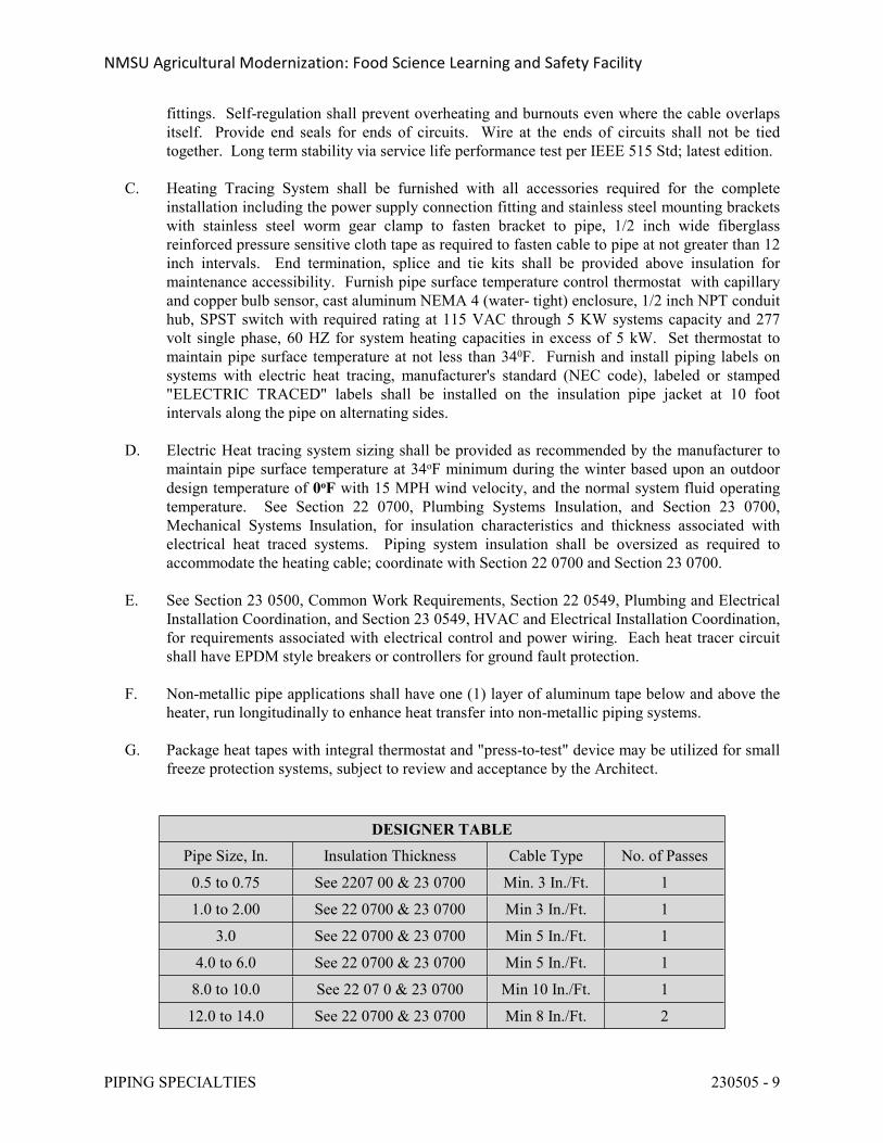
NMSU Agricultural Modernization: Food Science Learning and Safety Facility
PIPING SPECIALTIES 230505 - 9
fittings. Self-regulation shall prevent overheating and burnouts even where the cable overlaps itself. Provide end seals for ends of circuits. Wire at the ends of circuits shall not be tied together. Long term stability via service life performance test per IEEE 515 Std; latest edition.
C. Heating Tracing System shall be furnished with all accessories required for the complete installation including the power supply connection fitting and stainless steel mounting brackets with stainless steel worm gear clamp to fasten bracket to pipe, 1/2 inch wide fiberglass reinforced pressure sensitive cloth tape as required to fasten cable to pipe at not greater than 12 inch intervals. End termination, splice and tie kits shall be provided above insulation for maintenance accessibility. Furnish pipe surface temperature control thermostat with capillary and copper bulb sensor, cast aluminum NEMA 4 (water- tight) enclosure, 1/2 inch NPT conduit hub, SPST switch with required rating at 115 VAC through 5 KW systems capacity and 277 volt single phase, 60 HZ for system heating capacities in excess of 5 kW. Set thermostat to maintain pipe surface temperature at not less than 340F. Furnish and install piping labels on systems with electric heat tracing, manufacturer's standard (NEC code), labeled or stamped "ELECTRIC TRACED" labels shall be installed on the insulation pipe jacket at 10 foot intervals along the pipe on alternating sides.
D. Electric Heat tracing system sizing shall be provided as recommended by the manufacturer to maintain pipe surface temperature at 34oF minimum during the winter based upon an outdoor design temperature of 0oF with 15 MPH wind velocity, and the normal system fluid operating temperature. See Section 22 0700, Plumbing Systems Insulation, and Section 23 0700, Mechanical Systems Insulation, for insulation characteristics and thickness associated with electrical heat traced systems. Piping system insulation shall be oversized as required to accommodate the heating cable; coordinate with Section 22 0700 and Section 23 0700.
E. See Section 23 0500, Common Work Requirements, Section 22 0549, Plumbing and Electrical Installation Coordination, and Section 23 0549, HVAC and Electrical Installation Coordination, for requirements associated with electrical control and power wiring. Each heat tracer circuit shall have EPDM style breakers or controllers for ground fault protection.
F. Non-metallic pipe applications shall have one (1) layer of aluminum tape below and above the heater, run longitudinally to enhance heat transfer into non-metallic piping systems.
G. Package heat tapes with integral thermostat and "press-to-test" device may be utilized for small freeze protection systems, subject to review and acceptance by the Architect.
DESIGNER TABLE
Pipe Size, In. Insulation Thickness Cable Type No. of Passes
0.5 to 0.75 See 2207 00 & 23 0700 Min. 3 In./Ft. 1
1.0 to 2.00 See 22 0700 & 23 0700 Min 3 In./Ft. 1
3.0 See 22 0700 & 23 0700 Min 5 In./Ft. 1
4.0 to 6.0 See 22 0700 & 23 0700 Min 5 In./Ft. 1
8.0 to 10.0 See 22 07 0 & 23 0700 Min 10 In./Ft. 1
12.0 to 14.0 See 22 0700 & 23 0700 Min 8 In./Ft. 2
NMSU Agricultural Modernization: Food Science Learning and Safety Facility
PIPING SPECIALTIES 230505 - 10
Designer Note: Coordinate with Division 26 for quantity of circuits.
2.24 EXPANSION JOINTS
A. Furnish and install corrugated bellows expansion joint, Hyspan Series 1500, Metra-Flex, Keflex, Proco, Flexonics, or equivalent, self-equalizing, 150 PSIG working pressure at 850oF, Class 150 ASA flange connections 1-1/2" size and above, single or dual center base configuration as shown on the drawings, constructed of corrugated Type 304 or 321 stainless steel, ring controlled, with integral stainless steel or Monel sleeve, and removable carbon steel external housing to protect bellows and support insulation. Furnish limit rods to prevent expansion joint from exceeding rated travel. Joint design shall be for maximum flexibility over 10,000 cycles minimum.
B. Expansion joint sizing and installation shall be as shown on the drawing and as recommended by the manufacturer.
C. Expansion joints shall be insulated with flexible 2" minimum thickness of high temperature fiberglass blanket insulation furnished with joint and installed under the external protective housing.
D. Contractor shall carefully check expansion joint limit rods and make adjustments as required to ensure proper joint movement and operation.
2.25 EXPANSION COMPENSATORS
A. Furnish and install expansion compensators, Hyspan series 8500, Metra-Flex, Keflex, Proco, Flexonics, or equivalent, stainless steel laminated bellows with stainless steel or carbon steel shroud, 175 PSIG pressure rating at 250oF, 2 inch straight line expansion and 1/2 inch contraction. Furnish copper tube with sweat ends for compensators installed in copper piping systems. Furnish standard wall carbon steel pipe tube for compensators installed in steel piping systems, threaded connectors for sizes 2" and smaller and Class 150 ASA flange connection for sizes 2-1/2" or larger.
B. Expansion compensators sizing and installation shall be as shown on the drawings and as recommended by the manufacturer.
2.26 PIPE ALIGNMENT GUIDES
A. Furnish and install factory fabricated steel pipe alignment guides, Hyspan Series 9500, Metra-Flex, Keflex, Proco, Flexonics, or equivalent, to maintain the longitudinal position of pipe centerline between expansion joints and compensators with axial restraint. Alignment guides shall consist of a bolted two-section outer cylinder and base with two-section guiding spider bolted tight to the pipe guide. Guide and spider shall be sized to clear pipe and pipe insulation and long enough to prevent over travel of spider and cylinder. Guides shall not be used for pipe support.
NMSU Agricultural Modernization: Food Science Learning and Safety Facility
PIPING SPECIALTIES 230505 - 11
B. Alignment guides shall be arranged and installed as shown on the drawings and as recommended by the manufacturer.
2.27 PIPE ANCHORS
A. Pipe anchors shall be constructed of welded steel as detailed on the drawings.
B. Pipe anchors shall be arranged as shown on the drawings and as required to properly control/piping system expansion and contraction in conjunction with system flexibility due to off-sets, bends, and loops and expansion joints and compensators.
PART 3 - EXECUTION
3.1 INSTALLATION
A. All specialties shall be installed in accordance with the best standard practices and as recommended by the manufacturer.
B. Install thermometers so they are easily readable from operator level.
C. Where thermometers, gauges, vents and test fittings occur in insulated piping systems or on insulated equipment, extension necks shall be provided to extend beyond the insulation.
3.2 AIR VENTS
A. Manual air vents shall be installed as specified herein and at the high points in all piping systems.
B. Automatic air vents shall be installed as specified herein and at locations indicated on the drawings. Automatic air vents shall be installed level and in accordance with manufacturer's directions to properly vent system, complete with individual isolation valves.
3.3 STRAINERS
A. All strainer screens, including basket strainers and suction diffusers, shall be removed and cleaned prior to commencing testing and balancing work and shall be maintained clean through project final acceptance by the Owner. Suction diffuser start-up strainers shall be removed prior to final system testing and balancing work.
NMSU Agricultural Modernization: Food Science Learning and Safety Facility
PIPING SPECIALTIES 230505 - 12
3.4 TEST AND ADJUSTMENT
A. Field adjust all water pressure regulating valves, flow switches, water level controls, steam pressure reducing valves and specialties to provide required system operation.
B. Field test and verify the operation of all safety devices including water and steam relief valves and temperature and pressure relief valves.
3.5 RELIEF VALVE DISCHARGE
A. Water pressure relief valve and water temperature and pressure relief valve discharges shall be piped full size to the outside of the building or discharged indirectly in a properly sized building floor drain or floor sink, and as allowed by the Building Mechanical and Plumbing Codes. When the operating discharge temperature is in excess of 212oF, the discharge shall be equipped with a splash shield or centrifugal separator.
B. Water reduced pressure backflow preventer discharge shall be piped full size to the outside of the building or discharged indirectly into a properly sized building floor drain or floor sink as allowed by the Building Mechanical and Plumbing Codes. Provide a bronze air gap funnel with stainless steel fasteners for installation under reduced pressure backflow prevention relief valve. Febco Model AGD or equivalent, 1" discharge pipe size for backflow preventer size through 2".
END OF SECTION 230505
NMSU Agricultural Modernization: Food Science Learning and Safety Facility
VALVES 230523 - 1
SECTION 230523 - VALVES
PART 1 - GENERAL
1.1 REQUIREMENTS
A. All Valves shall conform with current applicable provisions of the General Conditions, Supplemental General Conditions, and General Requirements.
B. All Valves shall meet the current MSS Specifications covering Bronze & Iron Valves. MSS-SP-80, MSS-SP-70, MSS-SP71, MSS-SP-85 where applicable.
C. Lead Ban: All systems and system components, pipe, fittings, and fixtures delivering water for human consumption shall be lead free.
1. Any product designed for dispensing potable water shall meet both the NSF 61 and NSF 372 test standards via third-party testing and certification.
2. Lead free refers to <0.25% weighted average lead content in relation to wetted surface of pipe, fittings, and fixtures in systems delivering water for human consumption, and solder and flux which does not contain more than 0.2% lead.
1.2 RELATED SECTIONS
A. Section 23 0500 for Common Work Requirements for HVAC.
B. Section 23 0523 for Valve Identification.
C. Section 23 0504 for Pipe and Pipe Fittings.
D. Section 23 2313 for Refrigerant Piping System.
E. Section 23 2119 for valves associated with underground pre-insulated piping systems.
F. Division 25 for Automatic Temperature Control Valves.
G. Division 21 for fire suppression system valves and tamper switches.
H. Division 22 for plumbing system.
1.3 SCOPE
A. Contractor shall furnish and install all valves and accessories necessary for satisfactory operation of the systems.
NMSU Agricultural Modernization: Food Science Learning and Safety Facility
VALVES 230523 - 2
1.4 VALVE REQUIREMENTS
A. All Gate, Globe, Check, Ball valves shall be manufactured by Milwaukee, Nibco, Apollo, Stockham, Powell, Crane, Tyco-Grinnell, or equivalent.
B. All lubricated plug valves shall be as manufactured by Rockwell, Walworth, Homestead, or equivalent.
C. Butterfly valves shall be as manufactured by Milwaukee, W. C. Norris, Centerline, Crane, Demco, Keystone, Tyco-Grinnell, Victaulic, Nibco, or Dezurik, or equivalent. Butterfly valves may be used for closed circuit chilled water, heating hot water (200oF maximum) run-around coil and heat pump circulating water systems and for condensing water systems. Butterfly valves shall not be used for domestic water or other non-specified service.
D. Ball valves shall be utilized in lieu of gate valves and globe valves for all HVAC and plumbing systems for sizes 2" and smaller.
E. Butterfly valves may be substituted for gate, globe and ball valves for specified services, and for other services as may be approved by the Architect.
F. All valves furnished under Division 22 and 23, of the same type, shall be products of a single manufacturer unless otherwise approved by Owner's Representative.
G. Provide gate and globe valves with packing that can be replaced with the valve under full working pressure.
H. Provide chain operators for valves 4" and larger installed within mechanical equipment spaces where valves center line is in excess of eight feet above the floor or operating platform and as otherwise indicated on the drawings.
PART 2 - PRODUCTS
2.1 GENERAL SERVICE VALVES, HVAC AND PLUMBING SYSTEMS
A. Gate Valves - 2" and Smaller, Class 125: Valves 2" and smaller shall be cast of ASTM B-62 bronze, Class 125 construction, solid disc, rising stem, gland packed, non-asbestos packing. Milwaukee 148 (Threaded) or equivalent; Milwaukee 149 (Solder), or equivalent.
B. Gate Valves - 2" and Smaller, Class 150: Valves 2" and smaller shall be cast of ASTM B-62 bronze, Class 150 construction, solid wedge disc, rising stem, union bonnet, gland packed, non-asbestos packing. Milwaukee 1151 (Threaded) or equivalent; Milwaukee 1169 (Solder), or equivalent
C. Gate Valves - 2" and Smaller, Class 300: Valves 2" and smaller shall be cast of ASTM B-62 bronze, Class 300 construction, solid wedge disc, rising stem, union bonnet, gland packed, non-asbestos packing. Milwaukee 1184 (Threaded) or equivalent.
D. Gate Valves - 2-1/2" and Larger, Class 125: Valves 2-1/2" and larger shall be of ASTM A-126
NMSU Agricultural Modernization: Food Science Learning and Safety Facility
VALVES 230523 - 3
Class B cast iron, flanged ends, Class 125 construction, OS & Y Type, rising stem, bronze trim, non-asbestos packing. Milwaukee F2885 or equivalent.
E. Gate Valves - 2-1/2" and Larger, Class 250: Valves 2-1/2" and larger shall be of ASTM A-126
Class B cast iron, flanged ends, Class 250 construction, OS & Y Type, rising stem, bronze trim, non-asbestos packing. Milwaukee F2894 or equivalent.
F. Globe Valves - 2" and Smaller, Class 125: Valves 2-1/2" and smaller shall be of ASTM B-62, Class 125 construction, bronze trim, gland packed, non-asbestos packing. Milwaukee 502 (Threaded), or equivalent; Milwaukee 1502 (Solder) or equivalent.
G. Globe Valves - 2" and Smaller, Class 150: Valves 2" and smaller shall be of ASTM B-62, bronze, Class 150 construction, bronze trim, composition disc, union bonnet, gland packed, non-asbestos packing. Milwaukee 590 (Threaded) or equivalent; Milwaukee 1590 (Solder), or equivalent.
H. Globe Valves - 2" and Smaller, Class 300: Valves 2" and smaller shall be of ASTM B-62, bronze, Class 300 construction, bronze trim, union bonnet, gland packed, non-asbestos packing. Milwaukee 572 (Threaded) or equivalent
I. Globe Valves - 2-1/2" and Larger, Class 125: Valves 2-1/2" and Larger shall be of ASTM A-126, Class B cast iron, flanged ends, Class 125 construction, bolted bonnet, gland packed, non-asbestos packing. Milwaukee F2981M or equivalent.
J. Globe Valves - 2-1/2" and Larger, Class 300: Valves 2-1/2" and larger shall be of ASTM A-126, Class B cast iron, flanged ends, Class 300 construction, bolted bonnet, gland packed, non-asbestos packing. Milwaukee F2983 or equivalent.
K. Check Valves - 2" and Smaller, Class 125: Valves 2" and smaller shall be cast of ASTM B-62 bronze, Class 125 construction, Y-pattern, swing type design, teflon seat, disc for steam service, Buna-N for water service. Milwaukee 509 (Threaded) or equivalent; Milwaukee 1509 (Solder) or equivalent.
L. Check Valves - 2" and Smaller, Class 150: Valves 2" and smaller shall be cast of ASTM B-62 bronze, Class 150 construction, Y-pattern, swing type design, bronze seat, composition disc, teflon seat disc for steam service, Buna-N for water service. Milwaukee 510 (Threaded) or equivalent; Milwaukee 1510 (Solder) or equivalent.
M. Check Valves - 2" and Smaller, Class 300: Valves 2" and smaller shall be cast of ASTM B-62 bronze, Class 300 construction, Y-pattern, swing type design, bronze regrinding disc. Milwaukee 507 (Threaded) or equivalent.
N. Check Valves - 2 1/2" and Larger, Class 125: Valves 2-1/2" and larger shall be of ASTM A-126 Class B, cast iron, flanged ends, Class 125 construction, bolted bonnet, bronze trim, swing type design. Milwaukee F2974M or equivalent.
O. Check Valves - 2 1/2" and Larger, Class 250: Valves 2-1/2" and larger shall be of ASTM A-126 Class B, cast iron, flanged ends, Class 250 construction, bolted bonnet, bronze trim, swing type design. Milwaukee F2970 or equivalent.
NMSU Agricultural Modernization: Food Science Learning and Safety Facility
VALVES 230523 - 4
2.2 STEAM SERVICE - ABOVE 80 PSIG TO 125 PSIG, MAXIMUM STEAM PRESSURE
A. Gate Valves - 2" and Smaller, Class 150: Valves 2" and smaller shall be cast of ASTM B-62 bronze, Class 150 construction, solid wedge disc, rising stem, union bonnet, gland packed, non-asbestos packing. Milwaukee 1151 (Threaded) or equivalent.
B. Gate Valves - 2 1/2" and Larger, Class 125:
1. Valves 2-1/2" and larger shall be of ASTM A-126 Class B, cast iron, flanged ends, Class 125 construction, OS & Y Type, rising stem, bronze trim, non-asbestos packing.
2. Provide factory installed glove valve bypass 1/2" size through 4" valve size, 3/4" size for 6" and 8" valve sizes and 1" for valve sizes 10" and larger, conforming to MSS specification SP.45.
3. Provide drilled and tapped hoses for drains conforming to SP-45 where shown on drawings and as required for proper installation.
4. Milwaukee F2885 or equivalent.
C. Globe Valves - 2" and Smaller, Class 150: Valves 2" and smaller shall be cast of ASTM B-62 bronze, Class 150 construction, bronze trim, composition disc, union bonnet, gland packed, non-asbestos packing. Milwaukee 590 (Threaded) or equivalent.
D. Globe Valves - 2-1/2" and Larger, Class 125: Valves 2-1/2" and larger shall be of ASTM A-126, Class B Cast Iron, flanged ends, Class 125 construction, bolted bonnet, bronze trim, gland packed, non-asbestos packing. Milwaukee F2981 or equivalent.
E. Check Valves - 2" and Smaller, Class 150: Valves 2" and smaller shall be cast of ASTM B-62 bronze, Class 150 construction, Y-pattern, swing type design, bronze seats, composition disc, teflon seat disc for steam service, Buna-N for water service. Milwaukee 510 (Threaded) or equivalent.
F. Check Valves - 2-1/2" and Larger, Class 125: Valves 2-1/2" and larger shall be cast of ASTM B-62 bronze, Class B, cast iron, flanged ends, Class 125 construction, bolted bonnet, bronze trim, swing type design. Milwaukee F2974M (Threaded) or equivalent.
2.3 STEAM SERVICE - ABOVE 125 PSIG TO 150 PSIG, MAXIMUM STEAM PRESSURE
A. Gate Valves - 2" and Smaller, Class 150: Valves 2" and smaller shall be bronze Class 150 construction, threaded connections. Milwaukee 1151 or equivalent as specified herein or equivalent.
B. Gate Valves - 2 1/2" and Larger, Class 250:
1. Valves 2-1/2" and larger shall be of ASTM A-126 Class B, cast iron, flanged ends, Class 250 construction, OS & Y Type, rising stem, bronze trim, non-asbestos packing.
2. Provide factory installed glove valve bypass 1/2" size through 4" valve size, 3/4" size for 6" and 8" valve sizes and 1" for valve sizes 10" and larger, conforming to MSS specification SP-45.
3. Provide drilled and tapped hoses for drains conforming to SP-45 where shown on
NMSU Agricultural Modernization: Food Science Learning and Safety Facility
VALVES 230523 - 5
drawings and as required for proper installation.4. Milwaukee F2894 or equivalent.
2.4 STEAM CONDENSATE VALVES
A. Gate Valves - 2" and Smaller, Class 150: Valves 2" and smaller shall be bronze, Class 150 construction. Milwaukee 1151 (threaded), Milwaukee 1169 (solder), as specified herein or equivalent.
B. Gate Valves - 2-1/2" and Larger, Class 125: Valves 2-1/2" and larger shall be cast iron, Class 125 construction, OS & Y pattern. Milwaukee F-2885, as specified herein or equivalent.
C. Check Valves - 2 1/2" and Smaller, Class 150: Valves 2-1/2" and smaller shall be bronze, Class 150 construction, threaded connections, Milwaukee 510, as specified herein or equivalent.
D. Check Valves - 2 1/2" and Larger, Class 125: Valves 2-1/2" and larger shall be cast iron, Class 125 construction, flanged connections. Milwaukee F2974M, as specified herein or equivalent.
2.5 BUTTERFLY VALVES
A. Valves 2-1/2" and larger shall be full lug pattern, ASTM A-126, Class B cast iron body, 416-SS stems, aluminum/bronze disc, EPDM liner and seats (-30oF to 275oF) w/rigid phenolic cartridge, 200 PSIG working pressure with Bubble tight shut-off. Valves shall be for mounting between flanges with lugs drilled and tapped so that pipe may be disconnected on either side of valve with opposite end remaining under pressure. Milwaukee ML-123-E or equivalent.
B. Valves 4" and smaller shall be provided with level handler operator with spring loaded lock stops. Valves 5" and larger shall be furnished with manual gear operator with hand wheel.
C. Valves installed for insulated services shall be provided with extensions, as required, such that operator does not interfere with insulation or insulation jacketing.
D. Butterfly valves furnished for use in grooved piping system shall meet the material specification requirements as specified herein.
2.6 BALL VALVES
A. Valves 2" and smaller shall be cast of ASTM B-62 bronze, Class 150 construction, 600 PSI W.O.G. Two-piece body, chrome plated ball, blowout proof stem, reinforced TFE seats, non-asbestos packing. Milwaukee BA-100 (threaded) or equivalent. Milwaukee BA-150 (solder) or equivalent.
B. Valves installed on insulated services shall be provided with extensions, as required, such that operator does not interfere with insulation or insulation jacketing. Cutting or notching of the insulation or bending of handles shall not be permitted.
NMSU Agricultural Modernization: Food Science Learning and Safety Facility
VALVES 230523 - 6
2.7 BALANCE VALVES
A. Valves 2" and smaller: Ball valve, bronze, Class 150 construction, 600 PSI W.O.G., Two piece body, Milwaukee BA-100 (threaded). Milwaukee BA-150 (soldered), as specified herein or equivalent.
B. Valves 2-1/2" and larger: Lubricated plug valve, cast iron construction, 175 PSI W.O.G., Class 125 flange connections, level handle for valves 4" and smaller, manual gear operator with handle wheel for valve 5" and larger. Walworth No. 1797F or equivalent.
C. Valves 2-1/2" and larger:
1. Butterfly valve, full lug pattern, as specified herein.2. Furnish level handle with infinite throttling positions and locking device for securing
handle in any position for valves 4" and smaller and manual gear operator with hand wheel for valves 5" and larger.
D. Flow control and Flow Balance Valves: For calibrated flow balance valves and automatic flow control valves, see Specification Section 23 0505, Piping Specialties.
2.8 NATURAL GAS VALVES
A. Valves 3/4" and Smaller: Bronze natural gas cock, Walworth No. 590 (square head), Walworth 591 (flat head) or equivalent.
B. Valves 3" and Smaller: Ball valve shall be cast of ASTM B-584 bronze, Class 250 construction, threaded connections, chrome plated big ball and stem, RDTFE seat and stem packing, blow-out proof stem, UL Listed for natural gas service, Apollo 80-100 Series or equivalent.
C. Valves 4" and Larger: Lubricated plug valve, cast iron construction, 175 PSIG W.O.G., threaded connection for valves 2" and smaller, Class 125 Flange connections, level handle operator. Walworth No. 1797F (Flanged) or equivalent.
2.9 MANUAL AIR VENTS AND DRAIN VALVES
A. For manual air vents and drain valves, see Specification Section 23 0505, Piping Specialties.
2.10 NON-SLAM SILENT CHECK VALVE
A. Check valves for pump discharge and other required non-slam silent operation, shall be center guided, suitable for vertical or horizontal installation position, cast iron in semi-steel body, bronze disc and trim, stainless steel spring, Buna-N seats, Class 125 or 250 construction, as required by the application, wafer or globe flanged pattern for valves 2" through 10" size and flanged pattern for valves 12" and larger. Milwaukee 1400 Series (wafer) or equivalent. Milwaukee 1800 Series (globe) or equivalent.
NMSU Agricultural Modernization: Food Science Learning and Safety Facility
VALVES 230523 - 7
2.11 TRIPLE DUTY VALVE
A. At the Contractor's option, triple duty valve may be utilized at pump discharge in lieu of non-slam check valve and balance/shut-of valve, see Specifications Section 23 0505, Piping Specialties.
PART 3 - EXECUTION
3.1 INSTALLATION
A. All valves shall be installed in locations which will allow easy operation and facilitate maintenance.
B. Gate and Globe valves shall be installed with stems horizontal.
END OF SECTION 230523
NMSU Agricultural Modernization: Food Science Learning and Safety Facility
MECHANICAL VIBRATION CONTROL AND ISOLATION 230548 - 1 23 05 48 - 1
SECTION 230548 - MECHANICAL VIBRATION CONTROL AND ISOLATION
PART 1 - GENERAL
1.1 WORK INCLUDED
A. This Section specifies the requirements for vibration control systems to be used in all phases of architectural, mechanical, process, electrical, and structural work.
B. This Specification provides the necessary design for the avoidance of excessive vibration in the building due to the operation of machinery or equipment and/or due to interconnected piping, ductwork, conduit, or structures.
C. Due to the nature of this facility the design criteria may exceed those of normal industrial construction. It is imperative that close attention be paid to all specifications and details for noise and vibration control.
1.2 RELATED WORK
A. In the event of conflict regarding mechanical vibration control requirements between this Section and any other Section, the provisions of this Section shall govern.
1.3 CONTRACTOR’S GENERAL RESPONSIBILITIES
A. The Contractor shall bring to the Architect's attention prior to installation any conflicts which will result in unavoidable contact between the building structure and the isolated equipment, piping, etc., described herein, due to inadequate space, etc. Corrective work necessitated by conflicts after installation shall be at the expense of the responsible contractor.
B. The Contractor shall bring to the Architect's attention prior to installation any discrepancies between the requirements of this Specification and field conditions, changes required due to specific equipment selection, etc. Corrective work necessitated by discrepancies after installation shall be at the expense of the responsible contractor.
1.4 DESIGN CRITERIA
A. Equipment, ductwork, piping and conduit shall not be installed which makes rigid contact with the structure unless it is allowed by this specification.
B. Pipe Anchors and Supports: Piping supports and anchors shall not interfere with free operation of vibration isolation systems. Stiff-leg support of piping supported on Type HS, or Type FSN isolators is not acceptable.
NMSU Agricultural Modernization: Food Science Learning and Safety Facility
MECHANICAL VIBRATION CONTROL AND ISOLATION 230548 - 2 23 05 48 - 2
C. Ductwork: Ductwork isolation requirements are based on duct equivalent diameters. For rectangular ductwork, the equivalent diameter is the diameter of duct having the same cross-sectional area.
D. Equipment Isolation Frames and Bases: Frames and bases used to support vibration isolated pumps shall be sized to provide support for pipe elbows.
E. Isolation/Absorption Products: The completed installation must be free of vibration and noise. Systems, equipment, or parts which vibrate or generate vibration unduly, or which generate or emit undue noise while in operation, shall: (1) be adjusted, repaired, or replaced as appropriate to obtain acceptable levels of vibration or noise, or (2) be supported on, or fitted with, suppression or absorption devices, or other means, which effectively prevent the transmission of vibration or noise beyond the offending item.
F. Resilient Wall, Ceiling, and Floor Penetrations: Provide resilient wall and ceiling penetrations for all piping, conduit, ductwork, etc. supported on Type HS or Type FSN isolators. Refer to resilient penetration details on the Drawings.
1.5 COORDINATION
A. The Work under this Section must be coordinated with all other mechanical, electrical and structural work in order to accomplish the interfacing necessary to provide a complete and operating system in conformance with the intent of the Subcontract Documents.
1.6 SUBMITTALS
A. Provide the following in addition to the standard requirements:
1. A general statement of materials and methods intended for use on this project within 45 days of subcontract execution or notice to proceed, whichever is later. Specific information shall be provided for all items described under the products section of this Specification. Complete specifications, descriptive drawings, catalog cuts, and descriptive literature, which shall include make, model, dimensions, weight and interface description with other work, shall be supplied. Complete performance data are required that shall indicate full compliance with specifications as outlined.
2. Complete detailed shop drawings showing the intended locations and construction features of all types of products specified. Shop drawings shall be submitted in a timely manner.
3. Catalog cuts and data sheets on specific vibration isolators shall be provided showing compliance with the specification.
4. An itemized list showing items to be isolated, the isolator type, model number, isolator loading and deflection, and reference to specific drawing showing frame construction where applicable.
5. Detailed selection data for each vibration isolator supporting equipment, including:
a. The equipment identification mark.b. The isolator type.c. The actual load.
NMSU Agricultural Modernization: Food Science Learning and Safety Facility
MECHANICAL VIBRATION CONTROL AND ISOLATION 230548 - 3 23 05 48 - 3
d. The static deflection expected under the actual load.e. The specified minimum static deflection.f. The additional deflection to solid under load.g. The ratio of spring height under actual load to spring diameter.
6. Drawings showing equipment frame construction for each machine, including dimensions, structural member sizes, and support point locations.
7. Written approval of the frame design to be used shall be obtained from the equipment manufacturer.
8. Drawings showing methods for suspension, of support, and guides.9. Drawings showing methods for isolation of piping, at penetrations of walls, slabs, and
beams.
PART 2 - PRODUCTS
2.1 ACCEPTABLE MANUFACTURERS
A. The intent of this specification is to ensure the highest standard of vibration isolation for this project. For this reason, all vibration isolation products and materials shall be furnished by a single manufacturer, who will be responsible for the proper installation and operation of all vibration isolation equipment and systems. The only exception will be internal vibration isolation that is integral with the equipment, such as internal isolators on air handling units.
B. All vibration-isolation mounts shall be supplied by one of the following approved manufacturers:
1. Mason Industries Inc. (M.I.), Hauppauge, New York.2. Kinetics Noise Control Inc. (K.N.C.), Dublin, Ohio.3. Vibration Mountings & Controls, Inc. (V.M.C.), Bloomingdale, NJ.
2.2 VIBRATION ISOLATORS
A. General:
1. Metal parts of vibration-isolation units shall be as follows: Galvanizing shall meet ASTM Salt Spray test Standards and Federal Test Standard no. 14.
a. Housing: Hot-dipped galvanized or fusion epoxy coated.b. Hardware (washers, nuts, bolts, etc.): Cadmium plated.c. Springs shall be neoprene coated.
2. All isolators installed outdoors shall have base plates with bolt holes for fastening the isolators to the support members.
3. Isolator types are scheduled to establish minimum standards. At the Subcontractor's option, labor-saving accessories can be an integral part of isolators supplied to provide initial lift of equipment to operating height, hold piping at fixed elevation during
NMSU Agricultural Modernization: Food Science Learning and Safety Facility
MECHANICAL VIBRATION CONTROL AND ISOLATION 230548 - 4 23 05 48 - 4
installation and initial system filling operations, and similar installation advantages. Accessories shall not degrade the vibration isolation system.
4. Static deflection of isolators shall be as indicated in Table 230550, Vibration Isolation Schedule. All static deflections stated are the minimum acceptable deflection for the mounts under actual load.
5. The use of nested springs or of multiple parallel springs within a single mount is not permitted.
B. Unit FSN (Floor Spring and Neoprene):
1. Spring isolators shall be free-standing and laterally stable without any housing. Spring diameter shall be not less than 0.8 times the compressed height of the spring at the design load. Springs shall have a minimum additional travel to solid equal to 50 percent of the actual deflection. Springs shall be so designed that the ratio of horizontal stiffness to vertical stiffness is approximately 1. All mounts shall have leveling bolts.
2. The spring element in the isolator shall either be set in a neoprene cup and have a steel washer to distribute the load evenly over the neoprene, or each isolator shall be mounted on a unit DNP isolator. If the DNP isolator is used, a rectangular bearing plate of appropriate size to load the pad uniformly in the range of 40 to 50 psi shall be provided. If the spring isolator is supplied with a neoprene friction pad, a stainless steel, aluminum, or galvanized steel plate shall be used between the friction pad and the DNP isolator. The DNP isolator, separator plate, and friction pad shall be permanently adhered to one another and to the bottom of the bearing plate.
3. If the isolator is to be fastened to the building structure and a unit DNP isolator is used under the bearing plate, neoprene grommets shall be provided for each bolt hole in the base plate. Bolt holes shall be properly sized to allow for grommets. Hold down bolt assembly shall include washers to distribute load evenly to the grommet. Bolts and washers shall be galvanized.
4. Unit FSN isolators shall be one of the following products, or approved equal, with the appropriate neoprene pad (if used) selected from Unit DNP:
a. Type SLF: M.I.b. Type FDS: K.N.C.c. Type AC or AD: V.M.C.
C. Unit FSNTL (Floor Spring and Neoprene Travel Limited):
1. Spring isolators shall be free-standing and laterally stable without any housing. Spring diameter shall be not less than 0.8 times the compressed height of the spring at the design load. Spring shall have a minimum additional travel to solid equal to 50 percent of the actual deflection. Springs shall be so designed that the ratio of horizontal stiffness to vertical stiffness is approximately 1. All mounts shall have leveling bolts. All mounts shall have vertical travel limit stops to control extension when weight is removed. The travel limit stops shall be capable of serving as blocking during erection of the equipment. A minimum clearance of 1/4 inch shall be maintained around restraining bolts and between the limit stops and the spring to avoid interference with the spring action.
2. The spring element in the isolator shall either be set in a neoprene cup and have a steel washer to distribute the load evenly over the neoprene, or each isolator shall be mounted on a unit DNP isolator. If the DNP isolator is used, a rectangular bearing plate of
NMSU Agricultural Modernization: Food Science Learning and Safety Facility
MECHANICAL VIBRATION CONTROL AND ISOLATION 230548 - 5 23 05 48 - 5
appropriate size to load the pad uniformly in the range of 40 to 50 psi shall be provided. If the spring isolator is supplied with a neoprene friction pad, a stainless steel, aluminum, or galvanized steel plate shall be used between the friction pad and the DNP isolator. The DNP isolator, separator plate, and friction pad shall be permanently adhered to one another and to the bottom of the bearing plate.
3. If the isolator is to be fastened to the building structure and a unit DNP isolator is used under the bearing plate, neoprene grommets shall be provided for each bolt hole in the base plate. Bolt holes shall be properly sized to allow for grommets. Hold down bolt assembly shall include washers to distribute load evenly to the grommet. Bolts and washers shall be galvanized.
4. Unit FSNTL isolators shall be one of the following products, or approved equal, with the appropriate neoprene pad (if used) selected from Unit DNP
a. Type SLR: M.I.b. Type FLS: K.N.C.c. Type AWR-1: V.M.C.
D. Unit FN (Floor Neoprene):
1. Neoprene isolators shall be neoprene-in-shear type with steel reinforced top and base. All metal surfaces shall be covered with neoprene. The top and bottom surfaces shall be ribbed. Bolt holes shall be provided in the base and the top shall have a threaded fastener.
2. The mounts shall include leveling bolts that may be rigidly connected to the equipment.3. Unit FN isolators shall be one of the following products or approved equal:
a. Type ND: M.I.b. Type RD: K.N.C.c. Type R/RD: V.M.C.
E. Unit NP (Neoprene Pad)
1. Neoprene pad isolators shall be one layer of 1/4-inch to 5/16-inch thick ribbed or waffled neoprene. Neoprene shall be 40 to 50 durometer. The pads shall be sized so that they will be loaded within the manufacturer's recommended range.
2. Unit NP isolators shall be one of the following products or approved equal:
a. Type W: M.I.b. Type NPS: K.N.C.c. Type Shear-Flex or Maxi-Flex: V.M.C.
F. Unit DNP (Double Neoprene Pad):
1. Neoprene pad isolators shall be formed by two layers of 1/4-inch to 5/16-inch thick ribbed or waffled neoprene, separated by a stainless steel or aluminum plate. these layers shall be permanently adhered together. Neoprene shall be 40 to 50 durometer. The pads shall be sized so that they will be loaded within the manufacturer's recommended range.
2. Unit DNP isolators shall be formed from one of the following products or approved equal:
NMSU Agricultural Modernization: Food Science Learning and Safety Facility
MECHANICAL VIBRATION CONTROL AND ISOLATION 230548 - 6 23 05 48 - 6
a. Type WSW: M.I.b. Type NPS: K.N.C.c. Multiple Layers of Type Shear-Flex or Maxi-Flex: V.M.C.
G. Unit HS (Hanger Spring):
1. Vibration-isolation hangers shall consist of a free-standing laterally stable steel spring set into a neoprene cup, contained within a steel housing. The neoprene cup shall be manufactured with a grommet (or other element) to prevent the hanger rod from contacting the hanger housing. A steel washer shall be provided in the neoprene cup to evenly distribute load onto the neoprene.
2. The plate or washer at the top of the spring shall be welded to the spring. The hanger rod shall be securely fastened to this plate or washer using lock nuts. The hanger rod shall have a diameter not less than 5/8 inch. This design represents a modification to the unit types given below. The modification is intended to limit the side-to-side motion of the hanger rod relative to the hanger casing.
3. Spring diameter and hanger housing lower hole sizes shall be large enough to permit the hanger rod to swing through a 30 degree arc before contacting the housing. Spring elements shall have minimum additional travel to solid equal to 50 percent of the actual deflection.
4. Upper hanger rod attachment shall be made through a neoprene rubber-in-shear element designed to avoid direct contact between the hanger rod and the isolator frame.
5. Springs shall be color coded for ease of identification and removable, for field connection.
6. Unit HS isolators shall be one of the following products or approved equal:
a. Type 30N (modified): M.I.b. Type SH (modified): K.N.C.c. Type RSH (modified): V.M.C.
2.3 EQUIPMENT BASES
A. Unit BSF (Base Steel Frame):
1. Steel base frames shall consist of structural steel sections sized, spaced, and connected to form a rigid base which will not twist, deform, or deflect in any manner which will negatively affect the operation of the supported equipment of the vibration-isolation mounts. Frames shall be adequately sized to support basic equipment units and mounts plus any associated pipe elbow supports, duct elbow supports, electrical control elements, or other components closely related and requiring resilient support in order to prevent vibration transfer to the building structure. The depth of steel frame bases shall be at least 1/10 the longest dimension of the base with a minimum depth of 6 inches, but not more than 12 inches. Frame bases shall include side mounting brackets for attachment to vibration isolators. Mounting brackets shall be located on the sides of the base that are parallel to the axis of rotation of the supported equipment.
2. Unit BSF base shall be supplied by the isolator manufacturer and shall be one of the following products or approved equal:
NMSU Agricultural Modernization: Food Science Learning and Safety Facility
MECHANICAL VIBRATION CONTROL AND ISOLATION 230548 - 7 23 05 48 - 7
a. Type WFSL: M.I.b. Type SFB or SRB: K.N.C.c. Type WFB: V.M.C.
B. Unit BIB (Base Inertia Base):
1. Concrete inertia bases shall be formed of stone-aggregate concrete (150 pounds per cubic ft.) and appropriate steel reinforcing cast between perimeter structural steel channels. Inertia bases shall be built to form a rigid base which will not twist, deform, or deflect, in any manner which would negatively affect the operation of the supported equipment or the vibration isolation mounts. Inertia bases shall be adequately sized to support basic equipment units and motors plus any associated pipe elbow supports, duct elbow supports, electrical control elements, or other components closely related and requiring resilient support in order to prevent vibration transfer to the building structure. Inertia base depth shall be at least 1/12 the longest dimension of the inertia base but not less than 6 inches and not more than 12 inches. The weight of the inertia base, as a minimum, shall be 1 to 2 times that of the total weight of the equipment (including the attached piping it is supporting and other applicable loads). In special applications such as reciprocating compressors, the inertia base weight requirement could be higher and shall be calculated on a case-by-case basis. Inertia bases shall include side mounting brackets for attachment to vibration isolators. Mounting brackets shall be located on the sides of the base that are parallel to the axis of rotation of the supported equipment.
2. The steel frame and reinforcement shall be supplied by the vibration isolator manufacturer. Concrete shall be provided by the appropriate Subcontractor.
3. Inertia bases used to support vibration-isolated pumps shall be sized to provide support for pipe elbows and suction diffuser. Inertia bases used to support vaneaxial fans shall be long enough to support fan diffusion cones.
4. Frame and reinforcement for Unit BIB bases shall be one of the following products or approved equal:
a. Type KSL: M.I.b. Type CIB-L or CIB-H: K.N.C.c. Type WPF: V.M.C.
2.4 SNUBBERS
A. Snubbers to limit the vertical and horizontal motion of the isolated equipment under seismic load shall be fabricated from steel. A neoprene pad, 1/4-inch minimum thickness, shall be affixed at the point of contact. There shall be no contact between snubbers and the inertia base or equipment support frame during normal operation. Minimum of one snubber per side, four total, shall be required on each base. Seismic snubbers shall meet seismic requirements defined in other standard specification sections.
B. Snubbers shall not be finally installed* until vibration isolators are in place and adjusted with actual operating loads.
* It is advisable to install temporary snubbers during construction to guard against seismic events.

NMSU Agricultural Modernization: Food Science Learning and Safety Facility
MECHANICAL VIBRATION CONTROL AND ISOLATION 230548 - 8 23 05 48 - 8
C. Snubbers should be equal to Model HS-4 manufactured by Kinetics Noise Control (K.N.C.), Model Z-1225 manufactured by Mason Industries (M.I.), or field-fabricated to a similar design.
2.5 FLEXIBLE CONNECTORS
A. Flexible Duct Connections: Flexible duct connections shall be supplied in accordance with industry standards. Material width shall be 150 percent of clear dimension in addition to width required for attachment. Flexible duct connections shall result in a loose and highly compliant connection. Provide 3-inch minimum clearance between equipment casing and ductwork.
B. Flexible Pipe Connections: Flexible pipe connectors shall be fabricated of Kevlar or nylon cord, fabric, and neoprene. Flexible pipe connections shall result in a flexible and highly compliant connection that can allow longitudinal, transverse, and angular movements and provide micro-vibration isolation. The flexible connections shall be selected and specially fitted, if necessary, to suit the system temperature, pressure, and fluid type. Rods or cables may be used to control extension of the connector if required by the manufacturer, but shall not inhibit movement necessary to provide sufficient vibration isolation. Flexible pipe connections shall be one of the following products or approved equal:
1. Type SFDEJ: M.I.2. Double Sphere (Type DS): Metraflex3. Type VMT: V.M.C.
C. Flexible Conduit Connections: Flexible conduit shall be formed of one continuous length of electro-galvanized spiral-wound steel strip. Liquid-tight flexible conduit shall be formed of one continuous length of electro-galvanized spiral-wound steel strip, with neoprene gasket.
2.6 THRUST RESTRAINTS
A. Thrust restraints shall consist of pre-compressed steel spring, neoprene cup, threaded rod, and angle brackets designed to resist the effects of fan thrust and prevent the collapse or over extension of flexible duct couplings and attendant short circuiting of the fan vibration isolation system.
B. Minimum operating deflection of steel spring shall not be less than 1/2 the deflection of the equipment support isolator.
C. Mason Industries, Inc.: Model WBI and Model WBD.
2.7 RESILIENT PENETRATION SLEEVE/SEAL
A. Provide resilient wall and ceiling penetrations for all piping, conduit, ductwork, etc., supported on vibration isolators. Refer to resilient penetration details on Drawings.
NMSU Agricultural Modernization: Food Science Learning and Safety Facility
MECHANICAL VIBRATION CONTROL AND ISOLATION 230548 - 9 23 05 48 - 9
2.8 RESILIENT LATERAL GUIDES
A. These units shall be the standard product of the vibration isolation mounting manufacturer, incorporating neoprene isolation elements which are specifically designed for providing resilient lateral bracing of vertically rising ducts or pipes.
B. Resilient penetration sleeve/seals shall be field fabricated from a pipe or sheet metal section that is at least 1 inch larger in each dimension than the penetrating element and is used to provide a sleeve through the construction penetrated. The sleeve shall extend 1 inch beyond the penetrated construction on each side. The annular space between the sleeve and the penetrating element shall be packed tightly with glass fiber or mineral wool to within 1/4 inch of the end of the sleeve. The remaining 1/4 inch space on each side shall be filled with acoustical sealant to form an airtight seal. The penetrating element shall be able to pass through the sleeve without contacting the sleeve. Alternatively, prefabricated sleeves accomplishing the same result are acceptable. Coordinate with penetration details shown on the Drawings.
C. Resilient lateral guides shall be one of the following products or approved equal:
1. Type ADA: M. I.2. Type MDPA: V. M. C.
PART 3 - EXECUTION
3.1 GENERAL
A. The Contractor shall obtain inspection from the Architect of any installation to be covered or enclosed prior to such closure.
B. The Contractor shall obtain written and/or oral instructions from the vibration isolation manufacturer as to the proper installation and adjustment of vibration isolation devices.
C. The Contractor shall correct, at no additional cost, all installations which are deemed defective in workmanship or materials by the Architect.
D. The Contractor shall be responsible for proper operation of all systems, minor sub-systems, and services provided under this Section. The Contractor shall coordinate startup procedures, calibration, and system check-out with all contractors involved. Any system operational problems shall be diagnosed. All correctional procedures shall be initiated by the various contractors as required to bring the system into compliance with the design, and the problem shall then be rechecked to verify that the system operates normally. Any remaining difficulties shall be brought to the attention of the Architect.
NMSU Agricultural Modernization: Food Science Learning and Safety Facility
MECHANICAL VIBRATION CONTROL AND ISOLATION 230548 - 10 23 05 48 - 10
3.2 ISOLATOR INSTALLATION
A. The installation or use of vibration isolators must not cause any change of position of equipment, conduit, piping or ducting, which would result in stresses in connections or misalignment of shafts or bearings. In order to meet this objective, equipment and attached systems shall be maintained in a rigid position during installation. The load shall not be transferred to the isolator until the installation is complete and under full operational load. All plumbing, piping, and ducting at mechanical equipment connections is to be fully supported by specified hangers. Mechanical equipment and vibration mounts shall not carry plumbing, piping, or ducting loads.
B. Equipment Isolator Installation:
1. Space saver brackets shall be used for equipment supported on Type FSN vibration isolators.
2. The minimum operating clearance between the underside of the frame or inertia base and the pad or floor shall be 1 inch.
3. The frame shall be placed in position and supported temporarily by shims prior to the installation of the machine or isolators.
4. After the entire system installation is completed and under full operational load, the isolators shall be adjusted so that the load is transferred from the shims to the isolators. When all isolators are properly adjusted, the shims will be barely free and shall be removed.
5. Seismic snubbers shall not be finally installed until vibration isolators are in-place and adjusted with actual operating loads.
C. Isolator Hangers
1. The isolators shall be installed with the isolator hanger box as close as possible to the structure.
2. The isolators shall be suspended from massive beams, never from slab diaphragms between beams.
3. Orientation of isolator assembly including support and load rods shall be within five degrees of vertical.
D. Thrust Restraints
1. Thrust restraints shall be provided in accordance with manufacturers recommendations for all horizontal discharge vibration isolated fans and air handlers where the air thrust exceeds 10 percent of the vibration isolated equipment weight.
2. Thrust is calculated in accordance with the following formula:
E. THRUST (LB) = TOTAL PRESSURE (INCHES W.C.) x 5.3 x AREA (SQ. FT.)
1. Thrust restraints shall be oriented parallel to the direction of thrust and located symmetrically about the center of thrust. Ducting at thrust restraints shall be designed to withstand thrust loading or an auxiliary structure shall be provided for thrust restraint mounting.
2. Thrust restraint shall not interfere with or restrict free operation of vibration isolation systems.
NMSU Agricultural Modernization: Food Science Learning and Safety Facility
MECHANICAL VIBRATION CONTROL AND ISOLATION 230548 - 11 23 05 48 - 11
3.3 PIPING ISOLATION
A. Pipe support isolation shall comply with the following general guidelines:
1. Spring isolators shall be selected for a static deflection, under load, of not less than 1 inch. Unit FSN or HS isolators (whichever is applicable to the mounting condition) shall be used.
2. Where lateral support of pipe risers is required within the limits of isolation specified below, this shall be accomplished by use of resilient lateral supports.
3. Pipes that penetrate the building structure within the limits of isolation specified below shall be isolated from the structure by use of resilient penetration sleeve/seals.
4. Drain piping connected to vibration-isolated equipment shall not contact the building structure or other non-isolated system unless it is resiliently mounted as described above.
5. Piping connected to vibration-isolated equipment shall be installed so that it does not strain or force out of alignment pipe flexes or vibration isolators supporting either the equipment or the piping.
6. Where pipes are racked together, the most stringent isolation requirement, as defined in this specification shall take precedence.
7. Piping, 2" diameter or greater, which is connected to vibration isolated equipment shall be isolated from the building structure using spring supports, resilient pipe guides, and resilient penetration sleeves (as applicable) for a distance of 25 feet or 50 pipe diameters, whichever is greater.
3.4 ELECTRICAL ISOLATION
A. Electrical service connections to all vibration isolated mechanical equipment shall be made with flexible conduit. Conduit shall provide a minimum 90 degree turn and result in a loose and compliant connection.
B. Transformers rated at or above 200 kVA shall be supported on Type DNP vibration isolation pads or provided with integral internal neoprene vibration mounts. For dry transformers, install the isolation beneath the core; for oil-filled transformers, install the isolation beneath the tank.
3.5 EQUIPMENT BALANCE REQUIREMENTS
A. All rotating equipment shall operate at speeds less than 80 percent of their true critical speed. Unless otherwise required, equipment shall be balanced according to the recommendations given in the following sections.
B. Equipment components such as motors, pump rotors, fan wheels, etc. shall be factory balanced, both statically and dynamically, to meet the field balance requirements described in Paragraph 3.7.C below.
C. Pumps, compressors, fans not covered below, and other rotating equipment shall be field tested in accordance with ANSI Standard S2.41 (current edition) by an independent company after installation and under actual operating conditions. Vertical and horizontal vibration of rotating equipment shall not be greater than 0.071 in/sec RMS (0.1 in/sec 0-peak) velocity. The
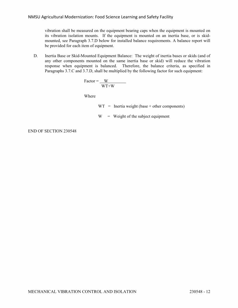
NMSU Agricultural Modernization: Food Science Learning and Safety Facility
MECHANICAL VIBRATION CONTROL AND ISOLATION 230548 - 12 23 05 48 - 12
vibration shall be measured on the equipment bearing caps when the equipment is mounted on its vibration isolation mounts. If the equipment is mounted on an inertia base, or is skid-mounted, see Paragraph 3.7.D below for installed balance requirements. A balance report will be provided for each item of equipment.
D. Inertia Base or Skid-Mounted Equipment Balance: The weight of inertia bases or skids (and of any other components mounted on the same inertia base or skid) will reduce the vibration response when equipment is balanced. Therefore, the balance criteria, as specified in Paragraphs 3.7.C and 3.7.D, shall be multiplied by the following factor for such equipment:
Factor = W WT+W
Where
WT = Inertia weight (base + other components)
W = Weight of the subject equipment
END OF SECTION 230548
NMSU Agricultural Modernization: Food Science Learning and Safety Facility
HVAC AND ELECTRICAL INSTALLATION COORDINATION 230549 - 1
SECTION 230549 - HVAC AND ELECTRICAL INSTALLATION COORDINATION
PART 1 - GENERAL
1.1 REQUIREMENTS
A. Conform with applicable provisions of the General Conditions, Supplemental General Conditions and General Requirements.
1.2 RELATED DIVISIONS AND SECTIONS
A. Division 1, LEED Commissioning.
B. Section 23 0500, Common Work Requirements for HVAC.
C. Division 25, Facility Management System.
D. Division 26 for Electrical.
E. Division 28 for Electronic Safety and Security.
1.3 SCOPE
A. It is the intention of this section to summarize the coordination of effort defined in the related sections and divisions of this specification.
B. If there is a conflict between this Section and other Sections and Divisions of this specification, this Section shall be the governing and decisive Section.
C. Make all connections to motors and controls for equipment supplied and/or installed under Division 23 according to Table 1 on the following page.
PART 2 - PRODUCTS
Not Applicable.
PART 3 - EXECUTION
3.1 INSTALLATION
A. No work shall be performed until the reviewed and marked submittal data have been reissued to the Contractor, unless written permission is obtained from the Architect.
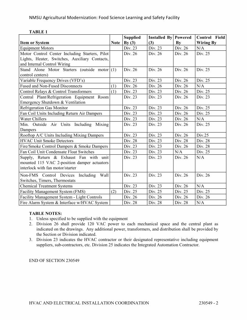
NMSU Agricultural Modernization: Food Science Learning and Safety Facility
HVAC AND ELECTRICAL INSTALLATION COORDINATION 230549 - 2
TABLE 1
Item or System NoteSupplied By (3)
Installed By (3)
Powered By
Control Field Wiring By
Equipment Motors Div. 23 Div. 23 Div. 26 N/AMotor Control Center Including Starters, Pilot Lights, Heater, Switches, Auxiliary Contacts, and Internal Control Wiring
Div. 26 Div. 26 Div. 26 Div. 25
Stand Alone Motor Starters (outside motor control centers)
(1) Div. 26 Div. 26 Div. 26 Div. 25
Variable Frequency Drives (VFD’s) Div. 23 Div. 23 Div. 26 Div. 25Fused and Non-Fused Disconnects (1) Div. 26 Div. 26 Div. 26 N/AControl Relays & Control Transformers (1) Div. 23 Div. 23 Div. 26 Div. 25Central Plant/Refrigeration Equipment Room Emergency Shutdown & Ventilation
Div. 23 Div. 23 Div. 26 Div. 23
Refrigeration Gas Monitor Div. 23 Div. 23 Div. 26 Div. 25Fan Coil Units Including Return Air Dampers Div. 23 Div. 23 Div. 26 Div. 25Water Chillers Div. 23 Div. 23 Div. 26 N/AMin. Outside Air Units Including Mixing Dampers
Div. 23 Div. 23 Div. 26 Div. 25
Rooftop A/C Units Including Mixing Dampers Div. 23 Div. 23 Div. 26 Div.25HVAC Unit Smoke Detectors Div. 28 Div. 23 Div. 28 Div. 28Fire/Smoke Control Dampers & Smoke Dampers Div. 23 Div. 23 Div. 26 Div. 28Fan Coil Unit Condensate Float Switches Div. 23 Div. 23 N/A Div. 25Supply, Return & Exhaust Fan with unit mounted 115 VAC 2-position damper actuators interlock with fan motor/starter
Div. 23 Div. 23 Div. 26 N/A
Non-FMS Control Devices Including Wall Switches, Timers, Thermostats
Div. 23 Div. 23 Div. 26 Div. 26
Chemical Treatment Systems Div. 23 Div. 23 Div. 26 N/AFacility Management System (FMS) (2) Div. 25 Div. 25 Div. 25 Div. 25Facility Management System - Light Controls Div. 26 Div. 26 Div. 26 Div. 26Fire Alarm System & Interface w/HVAC System Div. 28 Div. 28 Div. 28 N/A
TABLE NOTES:1. Unless specified to be supplied with the equipment2. Division 26 shall provide 120 VAC power to each mechanical space and the central plant as
indicated on the drawings. Any additional power, transformers, and distribution shall be provided by the Section or Division indicated.
3. Division 23 indicates the HVAC contractor or their designated representative including equipment suppliers, sub-contractors, etc. Division 25 indicates the Integrated Automation Contractor.
END OF SECTION 230549
NMSU Agricultural Modernization: Food Science Learning and Safety Facility
VARIABLE FREQUENCY DRIVES 230550 - 1
SECTION 230550 - VARIABLE FREQUENCY DRIVES
PART 1 - GENERAL
1.1 REQUIREMENTS
A. Conform with applicable provisions of the General Conditions, the Supplemental General Conditions, and General Requirements.
1.2 RELATED SECTIONS
A. Section 23 0500, Common Work Requirements for HVAC.
B. Section 23 3000, HVAC Air Distribution Systems and Equipment.
C. Section 23 0593, Testing, Adjusting and Balancing.
D. Division 25, Facility Management System.
E. Division 22, Section 22 0550, for plumbing variable frequency drives.
1.3 GENERAL
A. Variable frequency drives shall be coordinated with the equipment being furnished and the wiring coordinated with the Division 26 contractor.
B. Do not connect power factor correction devices in the electrical circuit serving any variable frequency drive or the motor downstream of the drive.
C. All associated equipment motors shall be inverter duty in compliance with standard NEMA MG 1 Part 31 to ensure the compatibility between the VFD and motor.
D. Manufacturer's Qualifications: Firms regularly engaged in manufacture of variable speed ac motor drives of types and ratings required, whose products have been in satisfactory use in similar service for not less than five years. All Division 23, HVAC and Division 22, Plumbing variable frequency drives shall be of one manufacturer/model series and be provided by the exclusive local representative for sole source responsibility of all aspects of sales, startup, service, training and warranty.
E. Variable frequency drives shall be manufactured by Asea Brown Boveri (ABB), Series ACH 550, or equivalent.
NMSU Agricultural Modernization: Food Science Learning and Safety Facility
VARIABLE FREQUENCY DRIVES 230550 - 2
1.4 SUBMITTALS
A. Refer to Sections 23 0500 for additional requirements.
B. Product Data: Submit manufacturer's data including catalog information, performance data efficiency, harmonic distortion, RFI/EMI (Radio Frequency Interference/Electromagnetic Interference) specifications, installation instructions and general recommendations for each type or size of motor.
C. The VFD manufacturer shall provide calculations as part of the shop drawing submittal specific to this installation showing total harmonic voltage distortion is less than 5%. Input line filters shall be sized and provided as required by manufacturer to ensure compliance with IEEE Standard 519-1992, "Guide for Harmonic Control and Reactive Compensation for Static Power Converters."
D. The manufacturer furnishing the variable frequency drives shall be responsible for noise created by VFD's and/or motors. The manufacturer shall submit his noise test data based on the following: Sound power level at any speed output of the VFD, measure 3 ft. from the motor, shall not exceed 1.2 times the sound power level of the motor running in bypass mode with 60 Hz incoming line power. Measurements shall be recorded at 10 (minimum) different operating speeds.
E. Shop Drawings: Submit dimensioned drawings of cabinet and front panel layout, showing accurately scaled switches, their layouts and proximity to associated equipment. Furnish control schematic connection diagram showing all field connections.
1.5 SCOPE
A. Furnish and install pulse width modulating (pwm) output wave HVAC Variable Frequency Drives (VFD) and control wiring between the VFD control system as specified in Section 23 0550.
B. The Variable Frequency AC Motor Drive shall be designed to convert the [460 volt] with a tolerated voltage window ± 30%, 3 phase, 60 Hz input power to 0 to [460 volt], 3 phase, 0-60 Hz variable frequency output power. The output frequency and voltage of the drive shall be variable such that a constant volts/Hz ratio is maintained throughout the operating range. The volts/Hz ratio shall be adjustable.
C. The drive shall be capable of operating any standard "off-the-shelf," NEMA B Design, squirrel cage induction motor with a 1.15 SF. The full load amp rating of the drive adjusted as required for jobsite elevation and ambient conditions shall be not less than 5% greater than the FLA rating of the motor or VFD must be oversized.
D. For maintenance purposes, the drive shall be capable of starting, stopping, and running with stable operation with the motor completely disconnected (no load).
E. Equipment will be designed and manufactured in accordance with applicable current NEMA, IEEE Standard 519-1992, (IEEE Guide for Harmonic Content and Control), UL 508, ISC 6
NMSU Agricultural Modernization: Food Science Learning and Safety Facility
VARIABLE FREQUENCY DRIVES 230550 - 3
Enclosures for Industrial Controls and Systems, and IEC 801-2, 801-4, 255-4 recommendations and be designed for installation per NEC. Equipment will have UL, CUL, or ETL Listing or CSA listing as approved and accepted by the state and local code authorities having jurisdiction.
PART 2 - PRODUCTS
2.1 VARIABLE FREQUENCY DRIVES
A. Each VFD shall be of the pulse width modulating design and shall consist of:
1. A full-wave diode bridge rectifier to convert incoming fixed voltage/frequency to a controlled DC voltage.
2. A DC bus filter with a power factor of .95 or better over the entire speed range.3. The drive efficiency shall be 97% or better at full speed and full load. Efficiency shall
not be less than 80% at 50% speed and load.4. An inverter section to change the controlled DC voltage to a PWM adjustable
voltage/frequency output for complete motor speed control. The inverter output will be generated by power transistors which will be controlled by six identical base driver circuits.
B. The VFD shall include the following:
1. The unit enclosure shall be NEMA Type 1, metal cabinet with front hinged access doors allowing access to all internal electric connections. Any VFD's mounted inside an equipment room with unducted return air and/or mounted in AHU (air handling unit) shall be furnished with NEMA type enclosure required by the local Construction Codes. All VFD's shall be UL Listed as plenum rated.
2. Electronic switching components shall be insulated gate/bipolar transistors, (IGBT).3. An externally operated, door interlocked, fused disconnect switch or circuit breaker shall
be provided. The base VFD shall be UL Listed with a short circuit interrupting rating of 100,000 symmetrical amps minimum without the need for input fuses. The DC Buss output shall be fused separately or electronically protected, with an indicating pilot light.
4. An internal 115V AC control power circuit with transformer and protective fuses shall be included or 250 mA of 24 VDC auxiliary power and be capable of loop powering a transmitter supplied by others.
5. Provide solid state relay interface for remote start/stop in both VFD and bypass mode independent of safety circuits.
6. Low frequency/low voltage start with linear adjustable ramp up to pre-selected speed. 7. Controlled acceleration and deceleration, separately adjustable, shall be provided from 2
to 180 seconds with torque limit override acceleration protection, and regeneration protection.
8. Critical Frequency lock out to skip over frequencies that may cause unstable operation in equipment being controlled. Provide at least three separate lockout settings.
9. The VFD 'run permissive circuit' will provide a normally open contact whenever a run command is provided (local or remote start command in VFD or bypass mode). The VFD system (VFD or bypass) shall not operate the motor until it receives a system ready
NMSU Agricultural Modernization: Food Science Learning and Safety Facility
VARIABLE FREQUENCY DRIVES 230550 - 4
command/contact closure.10. Furnish line reactors/inductors with minimum 5% impedance designed to provide proper
protection of harmonics and transients for the drive input power line. This is a minimum requirement and the manufacturer shall furnish higher rated line reactors or isolation transformers as may be necessary to maintain specified maximum total harmonic voltage distortion. Line reactors/transformers shall be factory mounted and wired within VFD enclosure. The 5% impedance reactors may be from dual (positive and negative DC bus) reactors, or 5% impedance AC line reactors. VFD's with only one 5% DC reactor shall add AC line reactors.
11. EMI / RFI (Radio Frequency Interference/Electromagnetic Interference) filters. All VFD's shall include EMI/RFI filters onboard to allow the VFD assembly to be CE marked and meet product Standard EN 61800-3 for the First Environment restricted level.
12. All components must be accessible from the cabinet door for service. The control shall be microprocessor based and the control card shall be the same part number and fully interchangeable for all ratings and voltages of VFD's.
13. Drive must be designed for against the wall and/or floor mounted arrangements, as required by the project installation requirements.
14. The drive shall be software programmed to provide automatic restart after a power outage or trip from overcurrent, over voltage, under voltage or over temperature. A delay shall occur before restart to allow motor to stop completely. The drive shall shut down and shall require manual restart if the automatic reset/restart function is not successful within 3-5 attempts within a short time period.
15. The VFD shall be capable of starting into a rotating load (forward or reverse) and accelerate or decelerate to setpoint without safety tripping or component damage (flying start). The VFD shall include a fireman's override input. Upon receipt of a contact closure from the fireman's control station, the VFD shall override all other inputs (analog/digital, serial communication, and all keypad commands) and force the motor to run at the adjustable, preset speed.
16. The VFD shall be equipped with an automatic extended power loss ride-through circuit which will utilize the inertia of the load to keep the drive powered. Minimum power loss ride-through shall be one-cycle, based on full load and no inertia. Removing power from the motor is not an acceptable method of increasing power loss ride-through.
17. Furnish terminal strip for external interlocks, isolated from the line and ground.18. Furnish prewired keypad with 3-position HAND-OFF-AUTO switches/buttons and
manual speed control that will incorporate "bumpless transfer" of speed reference when switching between "HAND" and "AUTO" modes. When in "HAND," the VFD will be started, and the speed will be controlled from the manual speed control. When in "OFF," the VFD will be stopped. When in "AUTO," the VFD will start via an external contact closure, and its speed will be controlled via an external speed reference.
19. The drive shall employ three (3) current limit circuits to provide trip-free operation:
a. The Slow Current Regulation limit circuit shall be adjustable to 125% (minimum) of the VFD's variable torque current rating. This adjustment shall be made via the keypad, and shall be displayed in actual amps, and not as percent of full load.
b. The Rapid Current Regulation limit shall be adjustable to 170% (minimum) of the VFD's variable torque current rating.
c. The Current Switch-Off limit shall be fixed at 255% (minimum, instantaneous) of the VFD's variable torque current rating.
NMSU Agricultural Modernization: Food Science Learning and Safety Facility
VARIABLE FREQUENCY DRIVES 230550 - 5
20. The overload rating of the drive shall be 110% of it's variable torque current rating for one (1) minute every 10 minutes, and 140% of it's "H" torque current rating for two (2) seconds every 15 seconds.
21. The VFD shall have door interlocked thermal magnetic circuit breaker which will disconnect all input power from drive and all internally mounted options when bypass is required. The disconnect handle shall be thru-the-door type, and be padlockable in the OFF position.
22. The VFD shall have input line fuses mounted in drive enclosure.23. The VFD shall be optimized for a 3 kHz carrier frequency to reduce motor noise. The
carrier frequency shall be adjustable by the start-up engineer. VFD shall reduce the carrier frequency based on actual VFD temperature that allows the highest carrier frequency without derating the VFD.
C. The VFD shall have a programmable digital operator's keypad located in the front door of the drive enclosure which shall include the following features and requirements.
1. All VFD’s shall have the same customer interface, including digital display, keypad and customer connections; regardless of horsepower rating. The keypad is to be used for local control (START/STOP, FORWARD/REVERSE, and speed adjust), for setting all parameters, and for stepping through the displays and menus.
2. A VFD mounted transfer switch motor selection option shall be provided to allow the operator to manually transfer between two motors. Interlocking shall be provided to prevent switching of the drive while operating. Use of external motor starters shall not be allowed.
3. The VFD shall give the user the option of either 1) displaying a fault, or 2) running at a programmable preset speed or last speed known if the input reference (4-20 mA or 2-10V) is lost; as selected by the user.
4. The VFD's shall utilize plain English digital display (code numbers are not acceptable). The digital display shall be a 40-character (2 line x 20 characters/line) LCD display. The LCD shall be backlit to provide easy viewing in any light condition. The contrast should be adjustable to optimize viewing at any angle. All set-up parameters, indications, faults, warnings and other information must be displayed in words to allow the user to understand what is being displayed without the use of a manual or cross-reference table.
5. There shall be a built-in time clock used to date and time stamp faults and record operating parameters at the time of fault. The clock shall also be programmable to control start/stop functions, constant speeds and four (4) separate, independent timer functions that have both weekday and weekend settings.
6. The VFD’s shall utilize pre-programmed application macro's specifically designed to facilitate start-up. The digital keypad shall be removable, capable of remote mounting and uploading/downloading parameters and HVAC specific Application Macros that shall provide one (1) command to reprogram all parameters and customer interfaces for a particular application to reduce programming time and initial start-up of multiple VFD's.
7. The VFD shall have a manual speed control integral to the keypad. 8. Analog meter - output percent of maximum speed.9. VFD shall have RS-485 port. The standard protocols shall be Modbus RTU, Johnson
Controls N2 bus, Siemens Building Technologies FLN and BACnet available. No additional hardware, firmware, gateways, etc., shall be required for these standard protocols. Optional protocols for Lon Works, Profibus, Ethernet, and DeviceNet shall be available, and have the protocol in each VFD. The use of third party gateways and multiplexers is not acceptable.
NMSU Agricultural Modernization: Food Science Learning and Safety Facility
VARIABLE FREQUENCY DRIVES 230550 - 6
10. All protocols shall be "certified" by the governing authority, non-certified protocols are not allowed. If additional gateway, hardware, etc., is required to obtain the BACnet, Modbus, etc., interfaces, the VFD manufacturer shall supply one (1) gateway, hardware device, etc., per VFD. Multiple VFD's sharing one (1) gateway, hardware, etc., shall not be acceptable.
11. BACnet connection shall be an RS485, MSTP interface operating at 9.6, 19.2, 38.4, or 76.8 Kbps. The connection shall be tested by the BACnet Testing Labs (BTL) and be BTL Listed. The BACnet interface shall conform to the BACnet standard device type of an Applications Specific Controller (B-ASC). The interface shall support all BIBBs (BACnet Interoperability Building Blocks) defined by the BACnet standard profile for a B-ASC.
12. All wires to be individually numbered at both ends for ease of troubleshooting.
D. The following operation information displays shall be standard on the VFD digital display. The display shall be complete English words (alpha-numeric codes are not acceptable):
1. Output Frequency2. Motor Current3. Calculated Motor Torque4. Calculated Motor Power5. DC Bus Voltage6. Output Voltage7. Heatsink Temperature8. Analog Input Values9. Keypad Reference Values10. Elapsed Time Meter11. kWh Meter
E. The drive shall have the following field adjustments:
1. Five (5) programmable critical frequency lockout ranges to prevent the VFD from continuously operating an unstable speed.
2. PID setpoint controller shall be standard in the drive, allowing a pressure or flow signal to be connected to the VFD, using the microprocessor in the VFD for the closed loop control. There shall be an independent, second PID loop that can be utilized to maintain setpoint of an independent process (i.e. valves, dampers, cooling tower bypass valve control, chilled water valve control, etc.
3. Two (2) programmable analog inputs shall accept a current or voltage signal for speed reference, or for reference and actual signals for PI controller. Analog inputs shall include a filter; programmable from 0.01 to 10 seconds to remove any oscillation in the input signal. The minimum and maximum values (gain and offset) shall be adjustable within the range of 0 - 20 mA and 0 - 10 volts. Additionally, the reference must be able to be scaled so that maximum reference can represent a frequency less than 60 Hz, without lowering the drive maximum frequency below 60 Hz.
4. Six (6) programmable digital inputs for maximum flexibility in interfacing with external devices.
5. Two (2) programmable analog outputs proportional to frequency, motor speed, output voltage, output current, motor torque, motor power, DC bus voltage, or active reference.
6. Three (3) programmable digital relay outputs. The relays shall be rated for maximum switching current 8 amps at 24 VDC and 0.4 amps at 250 VAC; maximum voltage 30
NMSU Agricultural Modernization: Food Science Learning and Safety Facility
VARIABLE FREQUENCY DRIVES 230550 - 7
VDC and 250 VAC; continuous current rating 2 amps RMS. Outputs must be true form "C" type contacts; open collector outputs are not acceptable.
7. Two (2) independently adjustable accel and decel ramps. These ramp times shall be adjustable from 1 to 1800 seconds.
8. Two (2) independently adjustable accel and decel ramps. These ramp times shall be adjustable from 1 to 1800 seconds.
9. The VFD shall ramp or coast to a STOP, as selected by the user.
F. Speed Command Input shall be via:
1. Keypad or manual speed control as selected by user.2. Two (2) analog inputs, each capable of accepting a 0-20mA, 0-10V, 2-10V signal. Input
shall be isolated from ground, and programmable via the keypad for different uses.3. Analog inputs shall have a programmable filter to remove any oscillation of the reference
signal. The filter shall be adjustable from 0.01 to 10 seconds. The analog input should be able to be inverted, so that minimum reference corresponds to maximum speed, and maximum reference corresponds to minimum speed. The minimum and maximum values (gain and offset) shall be adjustable within the range of 0-20mA and 0-10 volts.
4. Floating point input shall accept a three-wire input from a Dwyer Photohelic, or equivalent type instrument.
2.2 USER SELECTABLE AUTOMATIC/MANUAL BY-PASS (Operation of motor at full voltage at 60 Hz fixed speed).
A. Input line fused disconnect (service switch) and/or fast acting fuses exclusive to the VFD will allow the VFD to be disconnected from the line prior to clearing upstream branch circuit protection to maintain bypass capability. Door inter-locked, pad-lockable circuit breaker will disconnect all input power from the drive and all internally mounted options, together with fully rated magnetic motor starters mechanically interlocked shall be used to transfer motor to line power. Transfer must occur in orderly fashion causing no component damage to either drive or motor. Manual bypass circuitry must be integral part of drive cabinet. Separate bypass or starter enclosure is not acceptable. The VFD shall be UL Listed by the drive manufacturer and UL508 label complete bypass assembly.
1. An output contactor, bypass contactor and VFD only disconnect/service switch and/or fuses will be provided. Overload protection shall be provided in both drive and bypass modes.
2. Provide user selectable manual or automatic bypass.3. Bypass designs that incorporate fuses common to both the VFD and the bypass will not
be accepted. Three contactor bypass schemes are not acceptable, as a VFD input contactor is not a NEC recognized, lockable, physical disconnect and is an unacceptable means of safely disconnecting power to VFD.
4. The drive / bypass shall provide single-phase motor protection and under-voltage protection of bypass, contactor coils, etc., shall be in both the VFD and bypass modes.
5. The following operators shall be provided:
a. Bypass HAND-OFF-AUTO.b. Drive mode selector.c. Bypass mode selector.
NMSU Agricultural Modernization: Food Science Learning and Safety Facility
VARIABLE FREQUENCY DRIVES 230550 - 8
d. Bypass fault reset]
6. Dedicated digital input that will transfer motor from VFD mode to bypass mode upon dry contact closure for fireman's override. Two modes of operation: One mode forces the motor to bypass operation. The second mode as above also defeats all safeties and inputs (run until destruction).
B. Furnish auxiliary contacts to monitor drive status with FMS. A drive failure of any kind shall produce alarm signal and FMS.
PART 3 - EXECUTION
3.1 INSTALLATION
A. The drive shall be installed in strict accordance with manufacturer instructions. A minimum of 42" clearance shall be maintained in front of drives.
3.2 EQUIPMENT PROTECTION
A. Whenever possible drive shall be mounted within sight of motor that is controlled by drive. In the event that drive is not mounted within sight of motor, a disconnect will be installed (under Division 26) within sight of motor. If a disconnect is installed between motor and drive the drive supplier shall provide a 6" x 6" red engraved warning sign to be mounted at the disconnect which shall read as follows:
B. Drive shall include a coordinated AC transient protection system consisting of MOV's (Metal Oxide Varistors: phase-to-phase and phase-to-ground), a capacitor clamp, and 5% impedance reactors designed to protect itself against all normal transients and surges in the incoming power line, any grounding or disconnecting of its output power, and any interruption or run away of the incoming speed reference signal. Protection is defined as a normal shutdown with no component damage.
C. In general the drive shall contain the following protective circuits. In the case of a protective trip, the drive shall STOP, and announce the fault condition in complete words (alpha-numeric codes are not acceptable).
1. Overcurrent trip 200% of the VFD’s variable torque current rating.2. Overvoltage trip 130% of the VFD’s rated voltage.3. Undervoltage trip 60% of the VFD’s rated voltage.4. Ground Fault.5. Adaptable Electronic Motor Overload (I2t). The electronic motor overload protection
shall protect the motor based on speed, load curve, and external fan parameter. Circuits
NMSU Agricultural Modernization: Food Science Learning and Safety Facility
VARIABLE FREQUENCY DRIVES 230550 - 9
which protect the motor only at full speed are unacceptable.
3.3 OPERATING CONDITIONS
A. +/- 10% line voltage variations.
B. 5% incoming line frequency variations.
C. Maximum output frequency variations shall be +/- .25%.
D. FLA to meet or exceed UL/NEC table 430-150 of the minimum motor horsepower specified on the equipment schedule on the drawings.
E. Ambient temperature.
1. 0 to 50oC - NEMA 1 and 12 indoor enclosures: 1 thru 50 HP, 480 and 230 volt shall be capable of continuous operation as per VFD manufacturers documented/submittal data or VFD musts be oversized.
2. 0 to 40oC - NEMA 1 and 12 indoor enclosures: 60 thru 550 HP, 480 and 230 volt, shall be capable of continuous operation; from 49 to 50 Deg. C (104 to 122 Deg. F.), VFD current derate as per VFD manufacturers documented/submittal data or VFD must be oversized.
3. 0 to 50oC - NEMA 3R outdoor enclosures inclusive of all HP and voltages shall be capable of continuous operation as per VFD manufacturers documented/submittal data or VFD must be oversized.
F. Altitude.
1. 0 to 3300 feet above sea level without deration.2. Derate per manufacturer’s recommendation for project elevations above 3300 feet.
G. 90% Maximum humidity (non-condensing).
3.4 TESTING AND DOCUMENTATION
A. Manufacturer to conduct standard factory tests to assure compliance with specification requirements.
B. Manufacturer’s local Designated Service Station's startup technician shall provide field startup and commission of all VFD's and shall demonstrate trouble free, stable operation for conditions of starting, full load, three quarter load, half load, quarter load, no load and intermediate loads. The local Designated Service Station shall have factory trained and certified applications engineer/service personnel to provide service, training and warranty onsite 24/365 (24 hours / 365 days per year) and a toll-free support line. Provide four (4) hours onsite training of programming and operation.
C. Field tests shall include 100 hours of operation under load to demonstrate adequacy of equipment under thermal and voltage stresses, and that harmonic and other interferences do not
NMSU Agricultural Modernization: Food Science Learning and Safety Facility
VARIABLE FREQUENCY DRIVES 230550 - 10
adversely affect the electrical instrumentation and communications systems.
D. Manufacturers technically qualified and factory trained representative to make final written documents of installation, inspection and test run.
E. Field testing to include demonstration of automatic restart under operation of the following existing controls:
1. Fire Alarm.2. Nitestat.3. OFF/AUTO Switch.4. Clock Control.5. FMS START/STOP in both VFD and BYPASS MODE.
F. Switching from bypass to VFD operation both manually and automatically that shall be user selectable.
G. Complete records of test procedure and results to be made available at no additional cost to purchaser's representative.
H. Equipment shall carry a two (2) year guarantee as to workmanship, material, and satisfactory functioning from date of startup or maximum of 30 months from date of shipment from factory.
I. Furnish complete sets of their drawings showing control schematics, transistor schematics, wiring, outline dimensions, mounting details and equipment weight.
J. Operating & Maintenance Data and Spare Parts List - Furnish copies of all instruction books, spare parts lists and special bulletins covering on-site installation and operation in accordance with Section 23 0500.
END OF SECTION 230550
NMSU Agricultural Modernization: Food Science Learning and Safety Facility
TESTING, ADJUSTING AND BALANCING OF MECHANICAL SYSTEMS 230593 - 1
SECTION 230593 - TESTING, ADJUSTING AND BALANCING OF MECHANICAL SYSTEMS
PART 1 - GENERAL
1.1 GENERAL
A. Conform with applicable provisions of the General Provisions and the General Requirements. B. Testing, adjusting and balancing (TAB) shall be performed by a TAB Agency which is
independent of the Mechanical Contractor.
C. The TAB Agency’s efforts shall be paid for by the Owner and shall not be included in the mechanical contract price.
D. Unless specifically noted, all work specified in this section shall be included in the scope of the TAB Agency’s work. But some work described in this section is to be performed by the mechanical contractor, controls contractor, or others, and that work is specifically noted to be by these entities.
1.2 SCOPE
A. Provide TAB for the systems and equipment installed under Division 23, including but not limited to:
1. Supply and exhaust air systems including process and shops and laboratories systems.2. Return air where specifically noted.3. Hydronic systems including domestic HW return systems.
B. Provide all labor, instruments, and tools necessary to test, adjust and balance the systems shown on the drawings and/or described in these specifications. Check equipment performance, take measurements, adjust systems and equipment to provide specified performance, and report results. Submit reports to keep all parties posted on the progress of the TAB work.
C. Where the TAB effort indicates deficiencies in system performance, TAB Contractor shall take
the lead in a collaborative effort to trouble-shoot and resolve these deficiencies. Engage the assistance of others where necessary, starting with the Mechanical Contractor and Controls Subcontractor. Take additional measurements as required to identify the cause of the deficiencies, perform additional TAB as required to bring the system in compliance with the design intent. Engage the assistance of the Engineer and others where necessary. Indicate final setpoints and readings in a final TAB report.
1.3 STANDARDS AND DEFINITIONS
A. Perform all work in accordance with these specifications and the latest edition of the NEBB Standards.
B. Air Handling Unit: Where the term Air Handling Unit (AHU) is used in this spec section, it
NMSU Agricultural Modernization: Food Science Learning and Safety Facility
TESTING, ADJUSTING AND BALANCING OF MECHANICAL SYSTEMS 230593 - 2
shall include any factory fabricated or field erected unit that includes a fan and other components which filter, heat, cool, humidify or dehumidify the air stream. But the term AHU, where used in this section, does not include fan powered terminal units, fan coil units, unit heaters, cabinet unit heaters, etc.
C. Air Handling System: A fan or AHU and ductwork.
D. Hydronic System: A system in which a liquid is used to convey heat.
E. Record or Report: Where used as a verb, these terms mean to include in the TAB report.
1.4 QUALIFICATIONS
A. TAB agencies shall meet the following qualifications:
1. Membership in the Associated Air Balance Council (AABC), National Environmental Balance Bureau (NEBB) or the Testing, Adjusting and Balancing Bureau (TABB).
2. An office located within a 100 mile radius of the project site.3. A minimum of five (5) years experience in the TAB field.
B. The following TAB Agencies are prior approved:
1. Energy Balance & Integration2. Kirk Air Co.3. Native Air4. N-Demand Test and Balance LLC5. Air Moving Equipment Company
1.5 SUBMITTALS
A. Contractor shall submit the name of the proposed TAB agency prior to the TAB agency performing any services.
1. Submit a list of proposed personnel, including resumes with related project experience and certifications.
2. Submit proposed TAB procedures, instrumentation and measurement equipment including calibration data, and proposed sample TAB report forms.
B. Pre-Construction Report: Four weeks prior to the Mechanical Contractor installing the systems, the TAB Agency shall submit a letter indicating whether the design includes all devices the TAB Agency will need to successfully perform the TAB work. If any additional balancing devices are needed, the TABB Agency shall so note this in the pre-construction report.
C. Submit TAB reports as noted herein. Reports shall be in both hard copy and PDF format.
1.6 TAB PREPARATION AND COORDINATION
A. Mechanical Contractor shall perform the following in a timely fashion:
NMSU Agricultural Modernization: Food Science Learning and Safety Facility
TESTING, ADJUSTING AND BALANCING OF MECHANICAL SYSTEMS 230593 - 3
1. Provide the TAB Agency with the project documentation (drawings, specifications, bulletins, submittals, shop drawings, etc.) necessary to perform the TAB services.
2. Install, fill, pressure test, start up, clean, and the vent systems to be tested and balanced.
B. Controls Subcontractor shall perform the following in a timely fashion:
1. Install and make operational all necessary control systems and equipment, including computers and computer programs.
2. Provide qualified personnel to operate the systems as necessary to support the TAB effort. Provide the TAB contractor with the computer software necessary to facilitate the TAB effort.
3. Assist as required to resolve problems which become evident due to TAB work, and as required to obtain specified system performance.
PART 2 - PRODUCTS
2.1 EQUIPMENT
A. Provide all equipment and instruments necessary to perform the work specified herein. Calibrate and maintain instruments per NEBB Standards. Provide not less than the following:
1. Pitot tubes and draft gauges.2. Flow hood.3. Velometer.4. Thermometers.5. Pressure gauges.6. Flow meter test kit.7. Ampere – voltmeter.8. Speed indicator.9. Sound meter to measure eight octave bands.
PART 3 - EXECUTION
3.1 GENERAL
A. Review and inspect the mechanical systems for conformance with design documents. Test, adjust and balance all system flows under design conditions and under other conditions where part load testing is specified. Comply with measurement tolerances per NEBB. Balance to within 10% of design flows unless otherwise specified.
B. Visually mark the final settings of balancing dampers, balancing valves, fan speed controls, etc.
C. Comply with NEBB Standards. The descriptions included herein are a guide to the minimum information needed.
D. Troubleshooting: In the event that any areas fail to get proper flow, take the lead in
NMSU Agricultural Modernization: Food Science Learning and Safety Facility
TESTING, ADJUSTING AND BALANCING OF MECHANICAL SYSTEMS 230593 - 4
troubleshooting the system. Measure pressures, flows, etc. at various points throughout the systems as required to identify the cause of the deficiencies and identify upgrades which will resolve these deficiencies. Coordinate any remedial efforts directly with mechanical and controls contractors and re-test as required.
3.2 TEST AND BALANCE REPORT
A. Report shall be 8-1/2" x 11" bound into a complete and coherent report, except that drawings may be larger size, but still bound into the report. All forms shall be typewritten or legibly handwritten.
B. Include the following sections in the order indicated:
1. Cover sheet with the Project Name, Location, and the names of the Mechanical Contractor and Engineer
2. Table of Contents3. Summary indicating the highlights of the report and summarizing any deficiencies and
recommendations4. Test results including the names of the persons performing the tests and dates the tests
were performed5. Drawings6. Description of the test procedures used7. List of instruments used along with their calibration data8. Qualifications of personnel
C. Submit five copies and a PDF of the complete TAB report minimum two weeks before the first O&M instruction session. One copy will be returned to the Contractor with review comments.
3.3 BASIC AIR HANDLING SYSTEM TESTING, ADJUSTING AND BALANCING
A. General
1. Test all fans and air handling systems. Balance systems to achieve specified air flows while minimizing throttling losses.
2. Air Flow Measurements: Fan and AHU flow rates may be determined by pitot tube traverse or by measuring fan speed, suction and discharge pressures, and comparison with the fan curve. Measure duct air flows using pitot tube traverses. Measure air flows of grilles, registers and diffusers using either capture hoods or pitot tube traverses in the connected ductwork. Make such other tests as may be required to demonstrate that systems perform per the design requirements.
3. Air Flow Measuring Stations: Calibrate each air flow measuring station which is provided as part of the construction contract. Use duct pitot tube traverses or other appropriate means to measure air flows. Coordinate with the flow measuring station supplier, and enter calibration coefficients into the FMS. Record the results of this effort.
4. Alert Mechanical Contractor and Engineer if any fan or air handling unit (AHU) appears to be operating in an improper or unsafe condition.
5. Seal all test holes in ductwork once testing is complete. Repair insulation jackets to maintain the integrity of the vapor barrier.
6. Include in the report copies of ductwork drawings with test points indicated.
NMSU Agricultural Modernization: Food Science Learning and Safety Facility
TESTING, ADJUSTING AND BALANCING OF MECHANICAL SYSTEMS 230593 - 5
7. Variable Flow Systems: Verify proper fan tracking from full flow to 50% flow.
B. Fans: Perform the following for all fans, including those provided as part of an AHU.
1. Fan Nameplate: Record unit number per the equipment schedule, manufacturer, model, size, and serial number.
2. Performance Data: Measure air flow and adjust fan speed to achieve required flow. Record air flow, static pressure rise and fan speed.
a. Advise when belt and/or sheave changes are required to achieve the design flows. Mechanical contractor shall make the necessary changes as part of the mechanical contract. Approximately 25% of fans may require a sheave and/or belt change.
3. Current and Voltage: Record motor nameplate and measured voltage and amperage. Advise if motor amps exceed rated load amps.
C. Air Handling Units:
1. Outside Air: Test outside air flows using a pitot tube traverse and balance as required. If a traverse is not practical, use the mixed air temperature method if the inside and outside temperature difference is at least 20 deg F, or use the difference between pitot tube traverses of the supply and return air ducts.
2. Static Pressure: Measure and record the static pressure at the inlet and outlet of each AHU component, including louvers, dampers, filters, coils, etc, and at each inlet and discharge duct connection.
D. Coils: Measure and record air and water flows and pressure drops.
E. Air Distribution Systems:
1. Zone, Branch and Main Ducts:
a. Adjust to within 10% of design air flows. Balance so that at least one zone balancing damper is wide open. Balance multi-diffuser branch ducts so that at least one outlet or inlet damper is wide open.
2. Air Terminal Units:
a. Calibrate flow sensors and enter design maximum and minimum flow setpoints into FMS.
b. Record terminal unit number, size, specified flow, agency measured flow, FMS measured flow, and DDC flow correction factors.
3. Diffusers, Registers and Grilles:
a. Test, adjust, and balance each diffuser, grille, and register to within 10% of specified design requirements. Record the size of each grille, diffuser, and register, initial flow measurement, and final measured flow.
b. Where rooms are indicated to be maintained at either positive or negative pressure, balance air flows to achieve these conditions under design flow conditions, and verify proper pressurization at minimum flow.
NMSU Agricultural Modernization: Food Science Learning and Safety Facility
TESTING, ADJUSTING AND BALANCING OF MECHANICAL SYSTEMS 230593 - 6
F. Fan Coil Units, Unit Heaters, Cabinet Unit Heaters, Air Curtains, Door Fans, Fan Powered Terminal Units and other devices with fans and coils:
1. For each unit, record unit number, manufacturer, model, size, motor HP, voltage and rated load amps and design air flow.
2. Measure and record initial air flows, along with final air flows, unit inlet and outlet static pressures, voltages, and motor amps.
3. Measure and record initial and final water flows and pressure drops.
G. Energy Recovery Units:
1. For each unit, record unit number, manufacturer, model, size, motor HP, voltage and rated load amps and design air flow.
2. Measure and record initial air flows, along with final air flows, unit inlet and outlet static pressures, voltages, and motor amps.
H. Duct Leakage Testing
1. Specification Section 23 3000 describes the requirements for duct leakage testing. Provide all instrumentation and labor to take the required measurements.
2. The Mechanical Contractor shall provide the fans and all other required work.3. Submit test report. Retest until ductwork complies with specified leakage criteria.
3.4 HYDRONIC SYSTEMS
A. General:
1. Prior to commencing hydronic balance:
a. Set valves to proper position per the sequence of operation. Open all coil valves to full open position. Set 3-way valves to full flow through system component.
b. Check pump rotation.c. Verify that system is adequately pressurized.d. Set temperature controls so all system components deliver maximum flow. e. Balancing may be done in sections.
2. Pumping Systems: Measure flows and determine operating characteristics of hydronic systems with pumps operating both independently and in parallel (where applicable). Make measurements at maximum flow.
3. Balance systems to minimize throttling out in the distribution, and to instead throttle at the pump discharge. Recommend impeller trimming if appropriate.
4. Measure and report performance readings on all pumps, coils, heat exchangers, heating and cooling water generating equipment, flow measurement devices, heat rejection equipment, etc. Measure and record the following for each item of hydronic equipment:
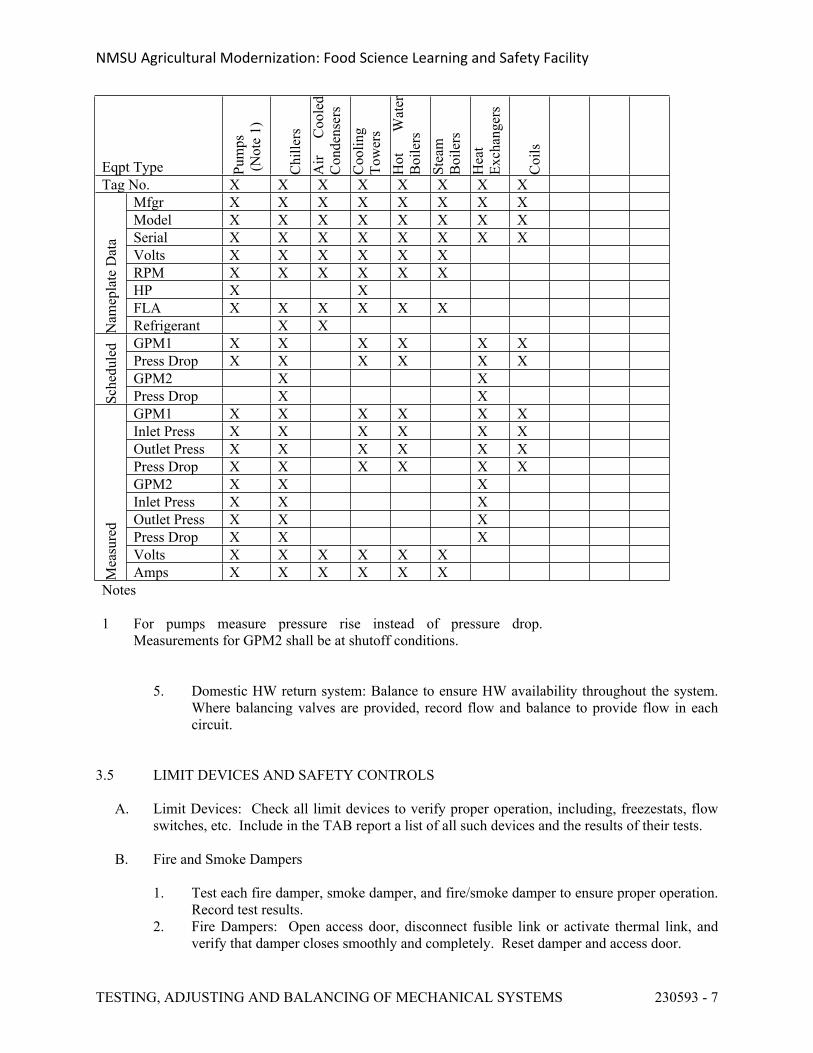
NMSU Agricultural Modernization: Food Science Learning and Safety Facility
TESTING, ADJUSTING AND BALANCING OF MECHANICAL SYSTEMS 230593 - 7
Eqpt Type Pum
ps (N
ote
1)
Chi
llers
Air
Coo
led
Con
dens
ers
Coo
ling
Tow
ers
Hot
W
ater
B
oile
rsSt
eam
B
oile
rsH
eat
Exch
ange
rs
Coi
ls
Tag No. X X X X X X X X Mfgr X X X X X X X X Model X X X X X X X X Serial X X X X X X X X Volts X X X X X X RPM X X X X X X HP X X FLA X X X X X X
Nam
epla
te D
ata
Refrigerant X X GPM1 X X X X X X Press Drop X X X X X X GPM2 X X
Sche
dule
d
Press Drop X X GPM1 X X X X X X Inlet Press X X X X X X Outlet Press X X X X X X Press Drop X X X X X X GPM2 X X X Inlet Press X X X Outlet Press X X X Press Drop X X X Volts X X X X X X
Mea
sure
d
Amps X X X X X X Notes
1 For pumps measure pressure rise instead of pressure drop. Measurements for GPM2 shall be at shutoff conditions.
5. Domestic HW return system: Balance to ensure HW availability throughout the system. Where balancing valves are provided, record flow and balance to provide flow in each circuit.
3.5 LIMIT DEVICES AND SAFETY CONTROLS
A. Limit Devices: Check all limit devices to verify proper operation, including, freezestats, flow switches, etc. Include in the TAB report a list of all such devices and the results of their tests.
B. Fire and Smoke Dampers
1. Test each fire damper, smoke damper, and fire/smoke damper to ensure proper operation. Record test results.
2. Fire Dampers: Open access door, disconnect fusible link or activate thermal link, and verify that damper closes smoothly and completely. Reset damper and access door.
NMSU Agricultural Modernization: Food Science Learning and Safety Facility
TESTING, ADJUSTING AND BALANCING OF MECHANICAL SYSTEMS 230593 - 8
3. Smoke Dampers: Open access door, activate damper, observe whether it closes smoothly and completely, and measure closing time. Reset damper and verify it opens completely. Close access door and record test results.
C. Life Safety Controls: Test and record life safety control operation of the HVAC systems. Verify the installation of required smoke detectors in air handling equipment, and verify operation of the smoke detector by activating the smoke detector and observing air handler shutdown or other required functions as described on the control drawings and sequence of operation. With assistance from the contractors for mechanical, temperature controls and electrical work, verify the operation of interconnected systems, such as the smoke detector's activation of the fire alarm system and the alarm system's activation of the life safety control sequence.
3.6 SOUND TESTING
A. Measure sound level in approximately ten percent of rooms as directed by Engineer.
1. Shut off mechanical equipment and measure background sound level in each octave band.
2. Start mechanical equipment and measure sound level in each octave band.3. Submit a plot of measured data against noise criteria (NC) curves.
B. Where measured sound levels are deemed by Owner to be unacceptable, work with Engineer and Mechanical Contractor to reduce actual levels, and retest as required.
3.7 AIR HANDLING SYSTEMS – SPECIAL APPLICATIONS
A. Rooms Requiring Air Flow Tracking and/or Active Room Pressure Control:
1. Calibrate flow sensors for all supply and exhaust air devices serving the room, and enter design maximum and minimum flow setpoints into FMS.
2. Calibrate room pressure sensor.3. Verify proper air flow tracking and room pressure control as the system operates from
maximum to minimum, and back to maximum flow. 4. Submit a separate sheet in the report for each such room. Include an air flow diagram
showing each device in the air flow and control system, and record all pertinent design and measured data on this sheet, including but not limited to:
a. Air valves: Tag number, size, specified flow, agency measured flows and FMS measured flows at various flow conditions, and DDC flow correction factors.
b. Offset air flows and room pressures at various flow conditions.
B. Rooms to be Balanced to a Positive or Negative Pressure (Without the Use of Air Flow Tracking or Active Pressure Controls):
1. Balance supply and return air flows as required2. Crack open the door and use a smoke puffer to demonstrate the direction of air flow.
Test under maximum and minimum flows. Record test results.
NMSU Agricultural Modernization: Food Science Learning and Safety Facility
TESTING, ADJUSTING AND BALANCING OF MECHANICAL SYSTEMS 230593 - 9
C. Room Tightness Testing:
1. Where a room tightness test is specified, provide the instrumentation and labor to perform such test.
2. The Mechanical Contractor shall provide the fans and associated ductwork for the test.3. Submit test report. Retest until room complies with room leakage criteria.
D. Fume Hoods and Shop’s Capture Hoods: Test exhaust airflow by duct pitot tube traverse, and
adjust exhaust air valve to control to within 5% of design flow. Balance makeup air flows as specified above. Test for turbulence and proper air flow patterns at the face and inside hoods using a smoke puffer or other approved smoke-emitting device. Document the test results, and advise of any concerns and recommendations.
E. Building/Zone Pressurization: Test and adjust building/zone pressurization by setting the design flows to meet the required flow direction and pressure differential. For positive pressure areas, set the supply air to design flow, and gradually reduce the exhaust air rate to obtain the required flow or pressure difference. For negative pressure areas, set the supply air to design flow, and gradually increase the exhaust air rate to obtain the required flow or pressure difference.
END OF SECTION 230593
NMSU Agricultural Modernization: Food Science Learning and Safety Facility
MECHANICAL SYSTEMS INSULATION 230700 - 1
SECTION 230700 - MECHANICAL SYSTEMS INSULATION
PART 1 - GENERAL
1.1 REQUIREMENTS
A. Conform with applicable provisions of the General Conditions, Supplemental General Conditions and General Requirements.
1.2 RELATED SECTIONS
A. Section 23 0500, Common Work Requirements for HVAC.
B. Section 23 0504, Pipe and Pipe Fittings.
C. Section 23 3000, Air Tempering System and Equipment.
1.3 SCOPE
A. Field insulation of piping: see drawings and Part 3 of this specification.
B. Field insulation of ductwork: See drawings, Table 23 0700-1, and Part 3 of this specification.
C. Field insulation of equipment supplied and/or installed under Division 23: See drawings and Part 3 of this specification.
D. Factory-insulated equipment and materials are described on the equipment schedule, on the drawings, and in other sections of this specification.
1.4 SUBMITTALS
A. Submit products to be used including insulation, jackets, miscellaneous products, and products for special applications. Review each application and advise if any product is either not suitable for, or not recommended for the application.
B. Verify that each submitted product meets all requirements for that product as specified herein. Include literature that clearly shows products meet all aspects of the spec. Include a cover sheet or letter with the following statement:
“Each product submitted here meets all specified requirements for that product except as follows:” followed by a list of any discrepancies.
C. Submit schedules showing the type of product and thickness for each application. Indicate products to be used on valves and fittings. Indicate where vapor barriers will be provided and what jackets will be used.
NMSU Agricultural Modernization: Food Science Learning and Safety Facility
MECHANICAL SYSTEMS INSULATION 230700 - 2
D. D-5, D-6 & D-7 insulation: If one of these insulations is specified, submit documentation indicating that the submitted materials are approved for the intended service.
E. Submit a description of the application techniques to be used.
1.5 QUALITY ASSURANCE
A. Comply with the latest edition of the National Commercial & Industrial Insulation Standards, as published by the Midwest Insulation Contractors Association.
B. Part 3 and Table 23 0700-1 give the system temperatures for various applications. Supplier shall review these temperatures and confirm the suitability of all components for the specified applications.
C. Test piping and ductwork in accordance with applicable specification sections before insulation is applied.
PART 2 - PRODUCTS
2.1 GENERAL
A. All materials must be 100% asbestos-free and 100% formaldehyde-free, NO EXCEPTION.
B. All materials must be GreenGuard Gold Certified.
C. Smoke and Fire Ratings: All materials shall have a composite fire and smoke hazard rating not exceeding flame spread 25, fuel contribution 50, smoke developed 50, when tested as assemblies per ASTM Standard E-84 or NFPA 255.
D. Thermal conductivities: Per ASTM C518. Do not exceed the conductivities indicated. Units listed herein for conductivity are Btuh-in/SF-F. Resistance shall not be less than the values specified herein. Units for resistance are SF-F/Btuh.
E. Noise Reduction Coefficients: Per ASTM C423 based on Type A mounting. NRC shall not be less than as specified.
F. Jackets: Maximum 0.02 perm water vapor transmission per ASTM E96 Procedure A.
1. ASJ: All service jacket per ASTM C1136 Type I, paintable white kraft paper outer surface reinforced with glass fiber yarn and bonded to aluminum foil, with self-sealing longitudinal lap and butt strips, breach puncture min. 50 oz-in/in tear per ASTM D781, tensile strength min. 30 lb/in per ASTM D828.
2. FSK: Foil skim kraft per ASTM C1136 Type II.
G. Fiberglass insulation: Inorganic fibers bonded with thermosetting resin.
H. Approved Manufacturers: Owens Corning, Johns Manville, Knauf, Certain-Teed, Kflex, Armacell, Unifrax -Insulfrax, Industrial Insulation Group, Pittsburgh Corning. Where the term
NMSU Agricultural Modernization: Food Science Learning and Safety Facility
MECHANICAL SYSTEMS INSULATION 230700 - 3
OAE is used herein, this refers to these manufacturers only. No other manufacturers are approved for this project.
2.2 PIPE INSULATION
A. General
1. Valves, Fittings, and Accessories: Use the same insulation materials and thickness as the pipe insulation, except as noted.
B. Type P-1, Fiberglass Pipe Insulation: Factory assembled insulation and ASJ. Pre-formed fiberglass per ASTM C547 Type I, suitable for use on surfaces from 0–850oF, with thermal conductivity 0.23 at 75oF or 0.33 at 250oF, and minimum 3 pcf density. ASJ shall have self-sealing lap at end and along length, with pressure sensitive tape lap sealing system. Owens Corning SSL II Pipe Insulation, Johns Manville Micro-Lok, Knauf Pipe Insulation.
1. Where Type P-1 insulation is used, insulate fittings, valves and accessories using one of the following:
a. Fiberglass pre-formed fitting insulation complying with the specification for P-1 pipe insulation, Johns Manville Hi-Lo Temp insulation inserts, Hamfab, OAE. Finish with Type J-2 fitting covers.
b. Where pre-formed fitting insulation is not available, the following may be used: minimum 0.75 pcf density fiberglass per spec for D-1 insulation except without FSK. Finish with Type J-2 fitting covers or with two coats of fitting mastic with fiberglass fitting tape embedded between coats.
C. Type P-2, Fiberglass Pipe and Tank Insulation: Similar to Type P-1 insulation and jacket, except with fibers oriented to allow insulation to be wrapped onto curved surfaces, with conductivity 0.30 at 100oF, or 0.55 at 400oF. Johns Manville Pipe & Tank Insulation, Owens Corning Pipe and Tank Insulation or Knauf Pipe and Tank Insulation.
1. Alternate: Fiberglass board insulation similar to Type D2, scored for application on curved surfaces, with ASJ.
D. Type P-3, Calcium Silicate Pipe Insulation: Rigid calcium silicate per ASTM C533, Type 1, asbestos-free, suitable for use on piping up to 1200oF, conductivity 0.55 at 700oF, compressive strength min. 200 psi at 5% compression. Industrial Insulation Group OAE.
1. Fittings, valves and accessories: Insulate with mitered Type P-3 insulation or Type D-7 insulation.
E. Type P-4, Elastomeric Foam Pipe Insulation: Pre-formed elastomeric foam, ASTM C534 Type 1 flexible, closed cell, suitable for use up to 220oF, UV protected, not to exceed flame spread 25 and smoke developed 50 based on 0.75-inch thickness, conductivity 0.30 at 75oF. Kflex, Armacell OAE.
1. Fittings, valves and accessories: Insulate using either Type P-4 insulation pre-formed for use on fittings and valves, or cut sections of P-4 pipe insulation to match the shape of the fitting or valve, taped on using PVC tape.
NMSU Agricultural Modernization: Food Science Learning and Safety Facility
MECHANICAL SYSTEMS INSULATION 230700 - 4
2.3 DUCTWORK INSULATION
A. Type D-1, Fiberglass Blanket: Factory fabricated insulation and FSK jacket assembly suitable for applications from 40-250oF, 3/4 pcf fiberglass, ASTM C553 Type I or II, with thermal resistance not less than the following for 2-inch thickness: 6.8 out of the box, 5.6 installed with 25% compression. Johns Manville Microlite XG Duct Wrap, Owens Corning Soft R Duct Wrap, Knauf Friendly Feel Duct Wrap, Certainteed Soft Touch Duct Wrap.
B. Type D-2, Fiberglass Board: Similar to Type D-1 except rigid board type, 3 pcf density, thermal conductivity 0.23 at 75oF, NRC 1.36, suitable for unfaced side at up to 450oF and faced side at up to 150oF. Johns Manville 800 Series Spin Glas, Owens Corning 700 Series Board, Knauf Insulation Board, Certainteed Certra Pro Commercial Board
C. Type D-3, Acoustic Lining (roll type): Organic fiber or fiberglass duct liner bonded with thermosetting resin, with factory-applied acrylic surface coating treated with anti-microbial agent, and factory-applied or shop-applied edge coating.
1. Properties: Minimum 1.5 pcf density, thermal conductivity 0.24, 6000 FPM rated per UL 181, NRC 0.70 at 1-inch thick and .95 at 2-inch thick. The product (fiberglass, resin, coating, microbial agent and adhesive) as an assembly shall be suitable for surfaces and gases up to 250oF, and shall comply with ASTM C1071 (Type I), G21 and G22.
2. Lining surface shall be cleanable using commercially available duct cleaning equipment when performed by qualified technicians using procedures established and recommended by the North American Insulation Manufacturer's Association (NAIMA) Duct Cleaning Guide.
3. Johns Manville Linacoustic RC, Owens Corning Acoustic R duct liner, Knauf EM duct liner, Certainteed ToughGuard R Duct Liner.
D. Type D-4, Acoustic Lining (board type): Similar to Type D-3 and complying with all aspects of the spec for Type D-3 insulation, except 3 pcf density rigid board with NRC 0.75 at 1-inch thick and 1.0 at 2-inch thick. Johns Manville Permacote Linacoustic R-300. Owens Corning Duct Liner Board, Knauf Rigid Plenum Liner, Certainteed Rigid Liner Board.
E. Type D-5, Grease Duct Applications: High temperature, foil-encapsulated inorganic blanket, 8 pcf. Insulfrax Fyre Wrap Max 2.0, Johns Manville Fire Temp, OAE. Product shall meet the following when applied as 2-layers around a grease-duct:
1. Tested and listed for zero clearance to combustibles across the entire surface of the blanket material per internal fire test AC101 or ASTM E2336 - Internal Fire Test – 2 Hr Grease Duct Enclosures.
2. Rated as a 2-hr fire resistive enclosure assembly per ASTM E-119, Engulfment Fire Test for 2-hr Grease Duct Enclosure.
F. Type D-6 –Combustible Materials within Plenum: For use on combustible materials located within supply or return air plenums, foil-encapsulated 8 pcf high-temperature ceramic fiber blanket suitable for service up to 1800oF. Unifrax Fyre-Wrap 0.5 plenum insulation.
G. Type D-7 – Fire Rated Ductwork: Suitable for continuous operation at 1800oF, 6-pcf, foil-encapsulated inorganic blanket to provide a 2-hour rating per ISO 6944 when applied in a single
NMSU Agricultural Modernization: Food Science Learning and Safety Facility
MECHANICAL SYSTEMS INSULATION 230700 - 5
1.5-inch thick layer. Insulfrax FyreWrap 1.5 OAE.
H. Type D-8 – Polystyrene Insulation: Rigid cellular square edge insulation per ASTM C578, waterproof, thermal conductivity 0.20, compressive strength 25 psi. Dow Styrofoam or Owens Corning Foamular.
I. Type D-9 – Fiberglass Ductboard: Listed per UL 181 as a Class 1 Rigid Air Duct; conforming to ASHRAE Std. 62, NFPA-90A and 90B, ASTM G-21 & G-22; rated for 2-in. wg; constructed of fiberglass bonded with a thermosetting resin, with double density slip joints pre-molded in the board; FSK jacket; thermosetting acrylic polymer interior surface, and black interior surface color. Thermal conductivity 0.23, and NRC 0.70 at 1-inch thick and 1.0 at 2-inch thick. Johns Manville Superduct 475 or 800, Owens Corning Quiet R Duct Board, Knauf Duct Board M, Certainteed ToughGard Duct Board
2.4 EQUIPMENT INSULATION
A. E-1, Removable Insulating Blanket: Factory fabricated, one-piece, removable and re-usable insulating blanket with fiberglass insulation completely enclosed within a silicone coated fiberglass cloth with draw cords of SS or PTFE coated glass fiber, and stainless steel clips. Insulation thickness shall be as specified elsewhere, but not less than 1-inch. Energy Systems Inc. “Q-Master” OAE.
2.5 INSULATION JACKETS
A. Type J-1, Metal Jacket: 0.010-inch smooth Type 304 stainless steel or 0.016-inch smooth or embossed aluminum per ASTM B-209, with minimum 1-mil polyethylene film with protective layer of 40 Lb virgin kraft paper, continuously laminated to full width inside jacket. Childers OAE.
1. Where jacket diameter is 16–96 in: 0.016-in. SS or 0.020 in. aluminum.2. Equipment heads and all surfaces where jacket is greater than 96-inch OD: 0.020-inch SS
or 0.024 inch aluminum.3. Fittings and Accessories: Provide the same jacket material as for pipe.
B. Type J-2, PVC Jacket: Minimum 20 mil sheets and 30-mil pre-molded fitting covers, ASTM D1784, Class 16354-C. Accessories include solvent weld solution, stainless steel tacks, and tape. All components shall be white, UV resistant, with paintable exterior surface, and suitable for use at –20 to +150oF. Johns Manville System 2000 (sheets), Zeston 300 (fitting covers), and Perma-Weld (solvent cement), OAE.
C. Type J-3, Canvas Jacket: 10 x 10 fiberglass mesh.
2.6 MISCELLANEOUS PRODUCTS
A. General:
1. Tapes: Aluminum, pressure sensitive, UL 181A-P listed and embossed, minimum 2.5-inch wide, Nashua 324A OAE.
NMSU Agricultural Modernization: Food Science Learning and Safety Facility
MECHANICAL SYSTEMS INSULATION 230700 - 6
2. Duct Liner Adhesives: Water-based, complying with ASTM C916.3. Solvent Cement for PVC Jackets: Johns Manville Perma-Weld OAE.4. Staples: Outward clinching, 0.5-inch galvanized steel
B. Piping Systems:
1. Pipe Hanger Insulation Inserts: Mechanical Pipe Shields Inc. “Snapp Itz” OAE.
C. Ductwork Systems:
1. Duct Liner Edge Sealer, Surface Sealer, Coatings & Adhesives: To meet ASTM C916. Johns Manville Superseal OAE.
2.7 SPECIAL APPLICATIONS
A. Handicap Lavatory Insulation Kit: Handi-Lav-Guard insulation kit per ANSI A117.1 with flexible vinyl finish.
PART 3 - EXECUTION
3.1 GENERAL
A. Delivery, Storage and Handling: Deliver and store insulation materials in factory-supplied containers. Protect from moisture. Do not install any materials that have gotten wet, regardless whether they are subsequently dried.
B. Store and apply materials in accordance with manufacturers’ recommendations, but not less than the following minimum temperatures. Ensure surfaces are clean and dry prior to application, and for minimum two hours after application:
1. Sealers, coatings, solvents and adhesives: 40oF.2. Tapes 50oF.
C. Install in accordance with manufacturer’s recommendations, NAIMA recommendations, and this spec. Provide good ventilation.
D. Where vapor barriers are specified, ensure that the entire system is vapor sealed.
E. Protect materials from water damage. Replace any materials that are water-damaged prior to substantial completion.
3.2 PIPING INSULATION
A. General: Insulate piping as indicated herein and/or on the drawings. Except as noted, insulate all valves, fittings, and accessories with the same material and thickness specified for the pipe. Where piping is specified with a separate insulation jacket provide this same jacket for valves, fittings and accessories. Vapor seal cold piping systems.
NMSU Agricultural Modernization: Food Science Learning and Safety Facility
MECHANICAL SYSTEMS INSULATION 230700 - 7
1. Where insulation terminates, provide insulating cement beveled for a neat finish. For vaporsealed piping, coat with insulating mastic prior to applying insulating cement.
2. Strainers and Suction Diffusers: Either Type P-1 or P-3 insulation. Make provisions to easily remove and re-install insulation.
3. Pipe Supports: Provide high density calcium silicate insulation or insulation inserts as specified. Maintain pipe jacket and vapor barrier at supports. If necessary, apply a heavy coating of vapor barrier mastic material to prevent condensation from forming on supports. Provide galvanized steel insulation shields to protect insulation and jackets at supports.
4. Penetrations Through Building Construction: Insulation shall be continuous where piping passes through walls, floors, and other construction. Where insulated piping passes through fire and/or smoke rated construction, provide a section of UL approved fire safing insulation to match the required insulation thickness, or provide an insulated pipe sleeve as manufactured by Pipe Shield, Inc., OAE.
5. Mechanical Couplings: Where mechanical couplings are permitted, insulate them as specified for fittings.
6. Steam Traps: Do not insulate.7. Retrofit Projects: Match the thickness of existing insulation where new insulation adjoins
existing. Integrate new vapor barrier with existing so the insulation barrier is continuous for both new and existing piping.
8. All voids formed by support saddles or other mounting or support hardware shall be filled with insulation.
B. Application:
Pipe Size Temp Range
Temp (F)
Insulation Type
Vapor Sealed
Under 1 1 - 1.5
Over 2 - 3 4 & 6
8 & Larger
TR-1 60&Less P-1 or P-4 Yes 1.5 1.5 1.5 1.5 1.5TR-2 61 – 104 P-1 Yes 0.5 0.5 0.5 0.5 0.5TR-3 105 - 140 P-1 No 1.0 1.0 1.0 1.0 1.0TR-4 141 - 200 P-1 No 1.5 1.5 2.0 2.0 2.0TR-5 201 - 250 P-1 No 1.5 1.5 3.0 3.0 3.0TR-6 251 - 350 P-1 No 1.5 2.5 3.0 3.0 3.0TR-7 Over 350 P-1 No 2.5 3.0 3.0 4.0 4.0
1. Temperature Range TR-1: Chilled water, refrigerant suction, condenser water (outdoor piping subject to freezing).
2. Temperature Range TR-2: Domestic cold water, makeup water, soft water, process water of any type, non-potable water, HVAC make-up water (except insulation is not required for evap cooler makeup piping outdoors), interior horizontal roof drain and overflow bowls and piping, condensate drains indoors.
3. Temperature Range TR-3: Domestic hot water (including non-circulating HW within interior walls and chases) and domestic HW return except as noted.
4. Temperature Range TR-4: Heating water supply and return, low pressure steam condensate, and pumped condensate return.
5. Temperature Range TR-5: Low pressure steam, blowoff, medium and high pressure steam condensate return.
6. Temperature Range TR-6: Steam at 16 - 120 psi.
NMSU Agricultural Modernization: Food Science Learning and Safety Facility
MECHANICAL SYSTEMS INSULATION 230700 - 8
7. Temperature Range TR-7: Steam above 120 psi.
C. Special Applications
1. Handicap Lavatories: Insulate domestic hot and cold water piping and P-traps exposed below handicapped lavatories with insulation kit specifically designed for the application.
2. Heat Traced Piping: Oversize insulation as required to accommodate heat tracing. Provide metal jacket.
3. Plastic pipe in return air plenums: Provide 0.5-inch type D6 insulation.4. Piping subject to freezing and heat traced piping: Insulate all such piping (including drain
piping) with thicknesses specified, but not less than 1.5-inch thickness. Oversize insulation to accommodate heat tracing where indicated. Provide J1 jacket.
5. Steam PRVs: Provide 1.5-inch type E1 insulation.
D. Type P-1 & P-2, Fiberglass Insulation: Install in accordance with manufacturer’s recommendations.
E. Type P-3, Calcium Silicate Insulation: Adhere to pipe or equipment using stainless steel wire. Provide removable J-1 jacket.
F. Type P-4, Elastomeric Foam: Seal all butt ends and longitudinal joints with Halstead Adhesive. When exposed to the weather, protect flexible tubing insulation with two coats of exterior weatherproof coating as recommended by manufacturer.
G. Jacketing: In addition to the finish and jacket specified for the particular type of insulation, provide the following:
1. Indoor piping exposed to physical damage Type J-2, PVC 2. Mechanical Eqpt Spaces: Exposed piping
less than 8 ft above floor or operator platform Type J-2, PVC 3. Exterior piping Type J-1, Metal 4. Tunnels Type J-2, PVC
3.3 DUCTWORK INSULATION
A. General:
1. Insulate all ducts except those specified to be uninsulated. The following ductwork need not be field insulated:
a. Factory insulated ductwork and plenums.b. Ducts with acoustic lining, provided the lining thickness matches or exceeds the
required insulation thickness.c. Exhaust ducts, except where noted.d. Return air ducts, except where noted.
2. See Table 23 0700-1 for additional information.3. Ensure that ductwork is leakage tested prior to applying insulation. Inspect ductwork and
repair any deficiencies prior to applying insulation. Do not apply insulation over deficient ductwork or plenum construction.
NMSU Agricultural Modernization: Food Science Learning and Safety Facility
MECHANICAL SYSTEMS INSULATION 230700 - 9
4. Ensure that ductwork is clean and dry before applying insulation.5. For ductwork with acoustic lining the drawings indicate the "clear inside duct dimension"
required. Over-size ducts as required to provide the required air flow area.
B. Type D-1, Fiberglass Blanket Insulation: Measure and cut insulation. Install so insulation is not excessively compressed at corners. For rectangular and flat oval ducts 24-inches and wider, provide stick pins and speed clip washers 18-inches on centers on the bottom, and clip off excess length of stick. Firmly butt insulation ends and longitudinal joints. Overlap jacket minimum 2-inches at end joints and longitudinal joints, staple on 6-inch centers, and continuously seal jacket. Provide vapor barrier mastic where ducts are indicated to be vaporsealed. Should gaps or fishmouths occur, re-staple and seal them with mastic. Use FSK tape and vapor barrier mastic to seal all penetrations of the FSK jacket, such as pins, tears, and hangers. Neatly trim and seal insulation at access doors, ends, damper rod controls etc. Verify proper damper operation.
C. Type D-2, Fiberglass Board Insulation: Attach with mechanical fasteners 12" on centers.
D. Type D-3 & D4, Acoustic Lining: Ductwork dimensions indicated on the drawings are net air flow dimensions inside liner. Increase duct size to accommodate liner. Completely line the inside surfaces of ducts and plenums specified and indicted. Comply with the NAIMA Fibrous Glass Duct Liner Standard (FGDLS), manufacturer’s recommendations, and this spec. Adhere liner with minimum 90% coverage of adhesive, and secure with mechanical fasteners and washers per FGDLS and manufacturer’s recommendations. Fastener length shall be sufficient to limit compression of liner to 1/8" maximum. Coat all cut edges and surface penetrations with edge sealer. Provide metal nosing for liner leading edges at fan discharge and for all ducts with air velocities exceeding 3,000 FPM. Maintain minimum 18-inch clearance from electric resistance heaters. Interrupt liner at dampers and apply external insulation at these locations.
1. Provide Type D-3 insulation for the 10 feet upstream of roof exhaust fans except in wet air streams.
E. Type D-5: Install insulation in a 2-layer system per manufacturer’s instructions, including the use of mechanical fasteners for the underside of ducts, butting or overlapping of joints, and offsetting of joints on outer layer.
F. Type D-6: Install in accordance with manufacturer’s instructions. Overlap seams and joints minimum 2-inches, affix with SS wire minimum 18-inches on centers, but not less than per manufacturer’s recommendations, and tape seams and joints with aluminum tape.
G. Type D-7: Install insulation in a single-layer system per manufacturer’s instructions. Mechanical fasteners for the underside of ducts shall be adhered to the duct in a manner suitable for the operating temperatures (welded or other suitable method). Butt or overlap joints per manufacturer’s recommendations.
H. Type D-8: Wire in place with SS wire minimum 12-inches on centers, and provide J-1 jacket.
I. Type D-9: Install per manufacturer’s recommendations, NAIMA standards, and SMACNA Fibrous Glass Duct Construction Standards. Provide ship lap seams and joints.
NMSU Agricultural Modernization: Food Science Learning and Safety Facility
MECHANICAL SYSTEMS INSULATION 230700 - 10
3.4 EQUIPMENT INSULATION
A. General: Where specified elsewhere, equipment will be factory insulated. Insulate all equipment as noted herein except portions of equipment that are factory insulated.
1. Fiberglass Board Insulation: Score, bevel, or miter to provide tight joints and secure in place with mechanical pin and clip fasteners and insulation bonding adhesive applied to underside surfaces, or with bands. Fill joints with insulation material and provide corner beads to protect edges of insulation.
2. Cold Tanks and Equipment: J3 jacket with two coats of approved vapor barrier mastic.3. Factory Packaged Equipment: Field insulate the equipment and piping on factory-
fabricated assemblies as if they were field installed, unless such items are factory insulated.
B. HW Pumps: Do not insulate.
C. Condensate Receivers: 1.5-inch Type D-2 or P-2 insulation with J-1 jacket.
D. Shell and Tube Heat Exchangers for Hot Service: 2-inch Type P-1 or P-2 insulation.
E. Plate and Frame Heat Exchangers for Hot Service: 2-inch Type D2.
F. Storage Tanks: 2-inch type P2.
3.5 JACKETING
A. Type J-1, Metal Jacketing:
1. Ducts: Slope jacketing to shed rain.2. Pipes: Install with seams at the 3 o'clock or 9 o'clock position to shed water. Band 12"
on centers.3. Joints and Seams: Overlap joints minimum 2-inches. Caulk with a weatherproof caulk
when located outdoors.
B. Type J-2, PVC Jacketing: Secure in place with tacks and solvent welded joints. White PVC tape may be used indoors.
C. Type J-3, Canvas Jacket: Apply mastic at a rate of 60 to 70 sq. ft. per gallon, embed fiberglass mesh, smooth all wrinkles and apply finish coat of Sealfas, or equivalent.
END OF SECTION 230700
NMSU Agricultural Modernization: Food Science Learning and Safety Facility
MECHANICAL SYSTEMS INSULATION 230700 - 11
TABLE 23 0700-1 DUCTWORK INSULATION
Notes:1 Includes Supply Air Duct from Energy Recovery Units and Evaporative Coolers. 2 Provide acoustical liner as indicated on the drawings.3 Delete Type D1 insulation if acoustical liner is indicated by plan notes or shown on the drawings. 4 Provide J1 Jacket.5 In hospitals do not provide acoustical lining in supply ductwork or plenums downstream of the final filter.6 Vaporseal ducts conveying cold air.7 Seal outdoor ductwork to prevent ingress of moisture.8 Insulate only the portion of exhaust ductwork between isolation damper and outside.
Service Location ConditionInsulation
Type
Insulation Thickness
(in) NotesSupply Air, Makeup Air, Outside Air Indoor Concealed D1 1.5 1, 6Supply Air, Makeup Air, Outside Air Indoor Exposed D2 1.5Supply Air, Makeup Air, Return Air Outdoor All D8 2 2, 4, 7Supply Rectangular Ductwork downstream of Terminal Units, Fan Coil Units, Heat Pumps, Blower Coils and Low Velocity AHU's
Indoor All D1 1.5 1, 3
Return Rectangular Ductwork upstream of Fan Coil Units, Heat Pumps, Blower Coils and Low Velocity AHU's
All All D1 1.5 1, 3
Ductwork indicated to be lined All All D3 1 5Ductwork indicated to be lined with 2-inch acoustic lining
All All D3 or D4 2 5
Single Wall Lined Plenums All All D4 2Transfer Air Ducts All All D3 or D9 1Exhaust Ductwork Indoor Concealed D1 1.5 8Exhaust Ductwork Indoor Exposed D2 1.5 8Kitchen Exhaust Ductwork Indoor All D5 2-layers Plastic Piping and Ductwork within RA Plenums Indoor Concealed D6 0.5
Fire-Rated Ductwork Other than Kitchen Exh Indoor All D7 1.5
Boiler Breeching & Stack Indoor All P1 or P2 3
Boiler Breeching & Stack Outdoor Exposed P1 or P2 3 4, 7
NMSU Agricultural Modernization: Food Science Learning and Safety Facility
MECHANICAL FACILITY STARTUP COMMISIONING 230800 - 1
SECTION 230800 - MECHANICAL FACILITY STARTUP/COMMISSIONING FOR HVAC
PART 1 - GENERAL
1.1 DESCRIPTION
A. Scope Of The Work
1. The purpose of this section is to specify Division 23 responsibilities and participation in the commissioning process. The owner will hire the Commissioning Authority for the project.
2. The Owner will hire the HVAC test and balance firm as denoted in Section 23 05 93. The Commissioning Authority will coordinate the activities of the HVAC test and balance firm.
3. The Contractor is responsible to provide support required for start-up, testing, and commissioning. The commissioning process requires significant participation of Division 23 to ensure all portions of the work have been completed in a satisfactory and fully operational manner.
B. Minimum requirements for Contractor:
1. Start-up and testing of the equipment supplied.2. Operate and maintain equipment and systems as required for commissioning tests.3. Providing qualified personnel including equipment manufacturer's service technicians for
participation with the commissioning team.4. Provide equipment, materials, and labor necessary to correct deficiencies found during
the commissioning process, which fulfill contract and warranty requirements.5. Provide operation and maintenance information and record drawings for verification,
organization, and distribution.6. Provide assistance to the Commissioning Authority (CA) to develop and edit equipment
startup and testing schedules (Commissioning Matrix).7. Provide training for the systems specified in this division with coordination by the
Contract Administrator and Commissioning Authority.8. Attend commissioning meetings.
1.2 RELATED WORK
A. All start-up and testing procedures and documentation requirements specified within Division 23.
B. Allow sufficient time before final commissioning dates so that testing, adjusting and balancing can be accomplished.
C. Put all heating, ventilating, and air conditioning equipment and systems into full operation and continue the operation during each working day of testing, adjusting and balancing and commissioning.
D. Provide labor and material to make corrections when required.
NMSU Agricultural Modernization: Food Science Learning and Safety Facility
MECHANICAL FACILITY STARTUP COMMISIONING 230800 - 2
1.3 DEFINITIONS
A. Point Verification Forms (PVF) are detailed installation and startup tracking documents developed by the Commissioning Authority and completed through a cooperative effort between the Contractor and the Commissioning Authority. The PVFs will track each point through installation, termination, and connection to the Facility Management System (FMS).
B. Functional Performance Tests (FPT) are detailed testing procedure developed by the Commissioning Authority, and conducted through a cooperative effort between the Contractor and the Commissioning Authority. The FPTs will be detailed step by step procedures developed for each HVAC system. Each FPT will have a clear acceptance criteria based in the contract documents which must be achieved before the system or sub-system is accepted by the Commissioning Authority and the Owner.
C. The Commissioning Authority (CA) is a firm hired directly by the Owner to oversee the entire commissioning process.
PART 2 - PRODUCTS
Not Applicable.
PART 3 - EXECUTION
3.1 WORK PRIOR TO COMMISSIONING
A. Complete all phases of work so the system can be started, tested, adjusted, balanced, and otherwise commissioned. Division 23 has primary start-up responsibilities with obligations to complete systems, including all sub-systems so they are fully functional and ready for startup and testing. This includes the complete installation of all equipment, materials, pipe, duct, wire, insulation, controls, etc., per the contract documents and related directives, clarifications, change orders, etc.
B. A commissioning plan will be developed by the CA and approved by the commissioning team. Division 23 is obligated to assist the CA in preparing the commissioning plan by providing all necessary information pertaining to the actual equipment and installation. If system modifications/clarifications are in the contractual requirements of this and related sections of work, they will be made at no additional cost to the Owner. If Contractor initiated system changes have been made that alters the commissioning process, notify the Commissioning Authority and Contract Administrator for approval.
C. Specific pre-commissioning responsibilities of Division 23 are as follows:
1. Bring each system into a fully operational state. This includes cleaning, filling, purging, leak testing, motor rotation check, control sequences of operation, full and part load performance, etc as required. The TAB firm will not begin the TAB work until each system is complete, including normal contractor start-up. The CA will not initiate FPTs until each system is complete, including normal contractor start-up and the TAB work has been completed.
NMSU Agricultural Modernization: Food Science Learning and Safety Facility
MECHANICAL FACILITY STARTUP COMMISIONING 230800 - 3
D. Commissioning is intended to begin upon completion of a system. Commissioning may proceed prior to the completion of systems, or sub-systems, and will be coordinated with the CA. Start of commissioning before system completion will not relieve Division 23 from completing those systems as per the schedule.
3.2 PARTICIPATION IN COMMISSIONING
A. Provide skilled technicians to start up all systems within Division 23. These same technicians shall be made available to assist the CA in completing the commissioning program as it relates to each system and their technical specialty. Work schedules, time required for testing, etc., will be requested, coordinated by the CA, and tracked on the Commissioning Matrix. Division 23 will ensure that the qualified technician(s) are available and present during the agreed upon schedules and for sufficient duration to complete the necessary tests, adjustment, and/or problem resolutions.
B. System problems and discrepancies may require additional technician time or reconstruction of systems and system components. The additional technician time shall be made available for the subsequent commissioning periods until the required system performance is obtained.
C. The Contract Administrator and CA reserve the right to judge the appropriateness and qualifications of the technicians relative to each item of equipment or system. Qualifications of technicians include expert knowledge relative to the specific equipment involved, adequate documentation and tools to service/commission the equipment, and an attitude/willingness to work with the commissioning team to complete the job.
3.3 WORK TO RESOLVE DEFICIENCIES
A. In some systems, misadjustment, misapplied equipment and/or deficient performance under varying loads will result in additional work being required to commission the systems. This work will be completed under the direction of the Contract Administrator, with input from the Contractor, equipment supplier, and CA. Whereas all members will have input and the opportunity to discuss the work and resolve problems, the Contract Administrator will have final jurisdiction on the necessary work to be done to achieve performance.
B. Corrective work shall be completed in a timely fashion to permit completion of the commissioning process according to the schedule. Experimentation to render system performance will be permitted. If the CA deems the experimentation work to be ineffective or untimely as it relates to the commissioning process, the CA will notify the Owner indicating the nature of the problem, expected steps to be taken, and the deadline for completion of activities. If deadlines pass without resolution of the problem, the Owner reserves the right to obtain supplementary services and/or equipment to resolve the problem. Costs incurred to solve the problems in an expeditious manner will be the Contractor's responsibility.
NMSU Agricultural Modernization: Food Science Learning and Safety Facility
MECHANICAL FACILITY STARTUP COMMISIONING 230800 - 4
3.4 TRAINING
A. Participate in the training of the Owner's engineering and maintenance staff, as required in Divisions 23, on each system and related components. Training, in part, will be conducted in a classroom setting, with system and component documentation, and suitable classroom training aids.
B. Training will be conducted by the Contractor and the equipment vendors.
C. Training for the Commissioning Team members on the Commissioning Plan will be provided by the CA. All Commissioning Team members are required to attend this training.
3.5 SYSTEMS DOCUMENTATION
A. In addition to the requirements of Division 23, update contract documents to incorporate field changes and revisions to system designs to account for actual constructed configurations. Red-line all drawings on two sets. Include architectural floor plans, elevations and details, and the individual mechanical or electrical systems in relation to actual building layout in Division 23 as-built drawings.
B. Maintain as-built red-lines as required by Division 1. Given the size and complexity of this project, red-line drawings at completion of construction, based on memory of key personnel, is not satisfactory. Continuous and regular red-lining of drawings is considered essential and mandatory. Maintain these drawings in the construction trailer and make them available for inspection at any time.
3.6 MISCELLANEOUS SUPPORT
A. Division 23 shall remove and replace covers of mechanical equipment, open access panels, etc., to permit Contractor, Contract Administrator, or CA to observe equipment and controllers provided.
END OF SECTION 230800
NMSU Agricultural Modernization: Food Science Learning and Safety Facility
HEATING HOT WATER SYSTEM AND EQUIPMENT 232113 - 1
SECTION 232113 - HEATING HOT WATER SYSTEM AND EQUIPMENT
PART 1 - GENERAL
1.1 REQUIREMENTS
A. Conform with applicable provisions of the General Conditions, Supplemental General Conditions and General Requirements.
1.2 RELATED SECTIONS
A. Section 23 0500, Common Work Requirements for HVAC.
B. Section 23 0504, Pipe and Pipe Fittings.
C. Section 23 0505, Piping Specialties.
D. Section 23 0523, Valves.
E. Section 23 0700, HVAC Insulation.
F. Division 25, Integrated Automation, for temperature control valves, meters and instrumentation.
G. Division 26, Electrical.
PART 2 - PRODUCTS
2.1 PIPING
A. Hot water heating piping shall be black steel pipe A53 grade A or B, seamless ERW or BW, standard wall Schedule 40 through 10" diameter. Larger diameter pipe shall have wall thickness as follows:
Pipe Diameter, Inches Wall Thickness, Inches
12" & larger 0.375
B. Contractor may use Type L hard drawn copper tubing, ASTM B88 for hot water piping sizes 2" and smaller. Proper insulating fittings, as specified in Section 23 0504, shall be installed to prevent electrolytic action between steel and copper piping connections.
NMSU Agricultural Modernization: Food Science Learning and Safety Facility
HEATING HOT WATER SYSTEM AND EQUIPMENT 232113 - 2
2.2 FITTINGS
A. Fittings for steel piping, 2" and smaller, shall be either screwed or welded. Screwed fittings shall be either Class 150, standard black malleable iron conforming to ANSI B16.3 or Class 125, standard black cast iron conforming to ANSI B16.4. Weld fittings shall be either standard weight steel butt-welding fittings conforming to ANSI B16.9 or forged steel socket-welding fittings, 2000 pound Schedule 40 conforming to ANSI B16.11.
B. Fittings for steel piping, 2-1/2" and larger shall be either standard weight steel butt-welding fittings, conforming to ANSI B16.9.
C. Fittings for copper piping shall be wrought copper conforming to ANSI B16.22, with 95-5 solder joints, as specified in Section 23 0504.
2.3 FLANGES
A. Flanges for steel piping system shall be forged steel, weld neck or slip-on, 1/16" raised face Class 150 flanges conforming to ANSI B16.5.
B. Flange connections for valves and equipment shall match the rating and drilling of the valves and equipment furnished.
C. Where specifically required by the application, black cast iron Class 125, standard threaded plain face companion flanges may be utilized for flanged connections in threaded piping systems.
D. Gaskets shall be 1/16" thick ring type or full face non-asbestos material suitable for the temperatures and pressure application.
E. Flange bolting shall be carbon steel machine bolts or studs and hex nuts, ASTM A307, Grade B.
2.4 VALVES
A. Valves other than automatic control valves are specified in Section 23 0523, HVAC Valves.
B. Automatic control valves shall be as specified in Division 25 Integrated Automation.
2.5 HOT WATER GENERATING EQUIPMENT
A. Hot water converters and associated auxiliary equipment shall be as specified on the equipment schedule on the drawings.
NMSU Agricultural Modernization: Food Science Learning and Safety Facility
HEATING HOT WATER SYSTEM AND EQUIPMENT 232113 - 3
2.6 PUMPS
A. Pumps shall be of the type and capacity listed in the Equipment Schedule. Pumps shall be selected so that the motors will not overload under any operating condition. Furnish one spare mechanical seal of each size required in conjunction with the pumps furnished under this Contract. All pumps shall have drain pans with tapped pipe connections and 3/4" drain line extended to floor drain. Pumps shall be installed so that they may be removed without the removal of the associated piping.
2.7 COILS
A. Hot water heating coils shall be as specified in Section 23 3000, and listed in the Mechanical Equipment Schedule.
2.8 EXPANSION TANK
A. Expansion tank shall be of the pressurized diaphragm type as specified in Section 23 0505 and listed on the Mechanical Equipment Schedule on the drawings.
2.9 WATER TREATMENT
A. Water treatment system, including shot type feeders shall be furnished by the Contractor.
B. Tanks shall be connected to the supply and return mains by means of 3/4" pipe with valves in each connection and with a 3/8" test cock on the supply connection. Tanks shall be wall or floor mounted on steel support adjacent to system pumps. The Contractor shall provide complete installation of water treatment equipment as shown on the drawings and as required by the Owner's designated Water Treatment Agency.
C. Chemicals as required for the system startup, operational testing and commissioning shall be provided by the Owner's designated Water Treatment Agency in sufficient quantities to maintain the level of chemical concentration recommended by the Water Treatment Agency and shall be included in the contract price. The exact type of chemical treatment compounds shall be determined by the Water Treatment Agency and approved by the Owner's Representative.
D. As a part of the contract price, the Contractor shall provide a one (1) year water treatment service contract by the Water Treatment Agency. Service contract shall include onsite testing on not less than a monthly basis and all required chemicals during the one (1) year project warranty period.
E. After system acceptance by the Owner, the continuing water treatment will be the Owner's responsibility.
NMSU Agricultural Modernization: Food Science Learning and Safety Facility
HEATING HOT WATER SYSTEM AND EQUIPMENT 232113 - 4
2.10 FLOW MEASURING STATIONS
A. Furnish and install water flow measuring station and automatic flow control valves where shown on the drawings and as specified in Section 23 0505.
PART 3 - EXECUTION
3.1 INSTALLATION
A. Piping installation shall conform to the requirements of Section 23 0500, Common Work Requirements for HVAC, Section 23 0504, Pipe and Pipe Fittings. Installation of specialties shall conform to the requirements of Section 23 0505, Piping Specialties.
3.2 CLEANING AND FLUSHING PIPING SYSTEMS
A. New heating water piping systems installed under this Contract shall be chemically cleaned of oils, greases, dirt and mill scale. The new piping system shall be inspected by the Owner's approved Water Treatment Agency to determine the appropriate cleanout procedures and recommended cleaning chemical materials.
B. Cleaning shall be performed in strict accordance with the chemical treatment agency and manufacturer's recommendations, and shall generally consist of the following:
1. Fill, flush, and drain piping systems with water to remove loose dirt and debris from the system.
2. Refill piping system with cleaning compounds, diluted to recommended concentrations and circulate for required time period.
3. Drain and flush system.4. Neutralize using caustic and soda ash as required when cleaning with acid compounds.5. Drain and inspect system and repeat cleaning if necessary.
C. In conjunction with piping system cleaning, clean and inspect all strainers and suction diffusers. Remove, bypass, or otherwise protect as necessary all piping system components which may be damaged due to chemical cleaning, including filters, instrumentation gauges, flow meters, etc.
D. After completion of chemical cleaning and flushing, the piping system shall be immediately refilled and maintained with treated water. Under no circumstances shall cleaned piping be allowed to sit empty or filled with untreated water.
NMSU Agricultural Modernization: Food Science Learning and Safety Facility
HEATING HOT WATER SYSTEM AND EQUIPMENT 232113 - 5
3.3 TESTS
A. All piping shall be proven tight at a hydrostatic pressure of 150% of the system design operating pressure, but not less than 125 PSI. The system shall show no loss in pressure or indication of leakage at any joint or connection for a period of one (1) hour.
END OF SECTION 232113
NMSU Agricultural Modernization: Food Science Learning and Safety Facility
CHILLED WATER SYSTEM AND EQUIPMENT 232114 - 1
SECTION 232114 - CHILLED WATER SYSTEM AND EQUIPMENT
PART 1 - GENERAL
1.1 REQUIREMENTS
A. Conform with applicable provisions of the General Conditions, Supplemental General Conditions and General Requirements.
1.2 RELATED SECTIONS
A. Section 23 0500, Common Work Requirements for HVAC.
B. Section 23 0504, Pipe and Pipe Fittings.
C. Section 23 0505, Piping Specialties.
D. Section 23 0523, Valves.
E. Section 23 0700, HVAC Insulation.
F. Division 25, Integrated Automation, for temperature control valves, meters and instrumentation.
G. Division 26, Electrical.
PART 2 - PRODUCTS
2.1 PIPING
A. Chilled water piping shall be black steel pipe ASTM A120 or A53 grade A or B, ERW or BW, standard wall Schedule 40 through 10" diameter. Larger diameter pipe shall have wall thickness as follows:
Pipe Diameter, Inches Wall Thickness, Inches
12" & larger 0.375
B. Contractor may use Type L hard drawn copper tubing, ASTM B88 for chilled water piping sizes 2" and smaller. Proper insulating fittings, as specified in Section 23 0504, shall be installed to prevent electrolytic action between steel and copper piping connections.
NMSU Agricultural Modernization: Food Science Learning and Safety Facility
CHILLED WATER SYSTEM AND EQUIPMENT 232114 - 2
2.2 FITTINGS
A. Fittings for steel piping, 2" and smaller, shall be either screwed or welded. Screwed fittings shall be either Class 150, standard black malleable iron conforming to ANSI B16.3 or Class 125, standard black cast iron conforming to ANSI B16.4. Weld fittings shall be either standard weight steel butt-welding fittings conforming to ANSI B16.9 or forged steel socket-welding fittings, 2000 pound Schedule 40 conforming to ANSI B16.11.
B. Fittings for steel piping, 2-1/2" and larger shall be either standard weight steel butt-welding fittings, conforming to ANSI B16.9 as specified in Section 23 0504.
C. Fittings for copper piping shall be wrought copper conforming to ANSI B16.22, with 95-5 solder joints, as specified in Section 23 0504.
2.3 FLANGES
A. Flanges for steel piping system shall be forged steel, weld neck or slip-on, 1/16" raised face Class 150 flanges conforming to ANSI B16.5.
B. Flange connections for valves and equipment shall match the rating and drilling of the valves and equipment furnished.
C. Where specifically required by the application, black cast iron Class 125, standard threaded plain face companion flanges may be utilized for flanged connections in threaded piping systems.
D. Gaskets shall be 1/16" thick ring type or full face non-asbestos material suitable for the temperatures and pressure application.
E. Flange bolting shall be carbon steel machine bolts or studs and hex nuts, ASTM A307, Grade B.
2.4 VALVES
A. Valves other than automatic control valves shall be specified in Section 23 0523, Valves.
B. Automatic control valves shall be as specified in Division 25, Integrated Automation.
2.5 PUMPS
A. Pumps shall be of the type and capacity listed in the Equipment Schedule, and shall be furnished with drip-proof motors. Pumps shall be selected so that the motors will not overload under any operating conditions. Furnish one spare mechanical seal of each size required in conjunction with the pumps furnished under this contract. All pumps shall have drain pans with tapped pipe connections and 3/4" drain line extended to floor drain. Pumps shall be installed so that they may be removed without the removal of the associated piping.
NMSU Agricultural Modernization: Food Science Learning and Safety Facility
CHILLED WATER SYSTEM AND EQUIPMENT 232114 - 3
2.6 COILS
A. Chilled water coils shall be as specified in Section 23 0505 and as listed on the Mechanical Equipment Schedule.
2.7 EXPANSION TANK
A. Expansion tank shall be of the pressurized diaphragm type as specified in Section 23 0505 and listed on the Mechanical Equipment Schedule on the Drawings.
2.8 PRESSURE RELIEF DEVICES
A. Refrigerant pressure relief devices and fusible plugs shall be installed with piping to a safe location in accordance with ANSI/ASHRAE Standard 15-1994. Discharge shall be to atmosphere at a location not less than 15 feet above the adjoining ground level and not less than 20 feet from any window, ventilation opening, or exit from any building. Discharge line sizing shall conform to ANSI/ASHRAE Standard 15-1994.
B. Each discharge pipe shall be equipped with a drip leg capable of holding 1 gallon of liquid. The drip leg shall include a manual drain valve.
2.9 WATER TREATMENT
A. Water treatment system, including shot type feeders shall be furnished by the Contractor.
B. Tanks shall be connected to the supply and return mains by means of 3/4" pipe with valves in each connection and with a 3/8" test cock on the supply connection. Tanks shall be wall or floor mounted on steel support adjacent to system pumps. The Contractor shall provide complete installation of water treatment equipment as shown on the drawings and as required by the Owner's designated Water Treatment Agency.
C. Chemicals as required for the system startup, operational testing and commissioning shall be provided by the Owner's designated Water Treatment Agency in sufficient quantities to maintain the level of chemical concentration recommended by the Water Treatment Agency and shall be included in the contract price. The exact type of chemical treatment compounds shall be determined by the Water Treatment Agency and approved by the Owner's Representative.
D. As a part of the contract price, the Contractor shall provide a one (1) year water treatment service contract by the Water Treatment Agency. Service contract shall include onsite testing on not less than a monthly basis and all required chemicals during the one (1) year project warranty period.
E. After system acceptance by the Owner, the continuing water treatment will be the Owner's
NMSU Agricultural Modernization: Food Science Learning and Safety Facility
CHILLED WATER SYSTEM AND EQUIPMENT 232114 - 4
responsibility.
2.10 FLOW MEASURING STATIONS
A. Furnish and install where shown on the drawings and as specified in Section 23 0505, water flow measuring stations and automatic flow control valves.
PART 3 - EXECUTION
3.1 INSTALLATION
A. Piping installation shall conform to the requirements of Section 23 0500, Common Work Requirements for HVAC, and Section 23 0504, Pipe and Pipe Fittings. Installation of specialties shall conform to the requirements of Section 23 0505, Piping Specialties.
3.2 CLEANING AND FLUSHING PIPING SYSTEMS
A. New chilled water piping systems installed under this Contract shall be chemically cleaned of oils, greases, dirt and mill scale. The new piping system shall be inspected by the Owner's approved Water Treatment Agency to determine the appropriate cleanout procedures and recommended cleaning chemical materials.
B. Cleaning shall be performed in strict accordance with the chemical treatment agency and manufacturer's recommendations, and shall generally consist of the following:
1. Fill, flush, and drain piping systems with water to remove loose dirt and debris from the system.
2. Refill piping system with cleaning compounds, diluted to recommended concentrations and circulate for required time period.
3. Drain and flush system.4. Neutralize using caustic and soda ash as required when cleaning with acid compounds.5. Drain and inspect system and repeat cleaning if necessary.
C. In conjunction with piping system cleaning, clean and inspect all strainers and suction diffusers. Remove, bypass, or otherwise protect as necessary all piping system components which may be damaged due to chemical cleaning, including filters, instrumentation gauges, flow meters, etc.
D. After completion of chemical cleaning and flushing, the piping system shall be immediately refilled and maintained with treated water. Under no circumstances shall cleaned piping be allowed to sit empty or filled with untreated water.
3.3 TESTS
NMSU Agricultural Modernization: Food Science Learning and Safety Facility
CHILLED WATER SYSTEM AND EQUIPMENT 232114 - 5
A. All piping shall be proven tight at a hydrostatic pressure of 150% of the system design operating pressure, but not less than 125 PSI. The system shall show no loss in pressure or indication of leakage at any joint or connection for a period of one hour.
END OF SECTION 232114
NMSU Agricultural Modernization: Food Science Learning and Safety Facility
PUMPS 232123 - 1
SECTION 232123 - PUMPS
PART 1 - GENERAL
1.1 SCOPE OF SERVICES
A. Supply pumps as specified herein, including freight to job site. Coordinate with Contractor for delivery and proper installation. Align pumps, instruct Owner’s operating personnel in proper operation and maintenance, and provide two sets of O&M Manuals.
1.2 WARRANTY
A. Provide parts and labor warranty for 18 months from shipment, 12 months from beneficial use. Warranty service must be guaranteed within four hours of notice, 24 hours per day, and 365 days per year.
1.3 SUBMITTALS
A. Five sets within one week after award: Full shop drawings for pumps and motors including assembly drawings; materials of construction; seal; motor HP, insulation, manufacturer, and full load motor efficiency; coupling; pump curve; and NPSH required.
PART 2 - PRODUCTS
2.1 PUMPS
A. General:
1. Factory assembled packaged pump and motor of bronze-fitted, cast iron construction, single-state, suitable for scheduled conditions of service. Entire assembly shall be finished with a suitable coating for long-term corrosion resistance.
2. General: Pump and motor mounted on steel or cast iron baseplate suitable for grouting in place, with raised lip drip pan and tapped drain connection. Coordinate rotation with piping and equipment layout.
3. Pump and motor capacities and efficiencies: Pump capacities shall be a minimum as scheduled, and suitable for parallel operation. Motors shall not exceed HP listed. Unit shall operate over the entire pump curve without exceeding the motor nameplate rating. Supplier may deviate from the pump and motor efficiencies listed as long as the total electric power required to drive all pumps does not exceed the total power per the schedules, and as long as no motors change in size.
4. Pump characteristics: Curve shall rise continuously from maximum capacity to shutoff, operation at or near peak efficiency, capable of operating over entire flow range listed at full speed without exceeding break-off point or exceeding manufacturer’s recommendations. Impeller diameter shall not exceed manufacturer’s minimum published diameter plus 90 percent of the difference between published maximum and
NMSU Agricultural Modernization: Food Science Learning and Safety Facility
PUMPS 232123 - 2
minimum impeller diameters.5. Casing: close grain cast iron, 175 psig rated, with 125 psi ASA flanges, plugged drain
and vent connections, and replaceable bronze wearing rings.6. Impeller: Centrifugal type, total enclosed, non-overloading, one-piece bronze impeller,
with entire rotating assembly statically, dynamically and hydraulically balanced.7. Shaft: Carbon steel, minimum AISI C1045.8. Motor: Squirrel cage induction type, 1.15 service factor, Class B insulation, premium
efficiency per IEEE Standard 112, Test Method B, 460/3/60, non-overlooking and suitable for continuous operation at any point along the pump curve.
9. Bearings: Grease lubricated, moisture and dust resistant housing, minimum 20,000 hour B-10 life (100,000 hour average life) under scheduled conditions of service.
10. Coupling: Flexible type with removable guard, similar to Waldon, Thomas, Falk, Fast or Woods.
B. Horizontal Split Case Type: Double suction type, ODP motor, and 316 stainless steel shaft sleeve.
1. Mechanical seals: Single, unbalanced, inside mounted, end face rubber bellows type with stainless steel spring, brass or stainless steel seal heads, carbon-graphite rotating washer, and renewable tungsten-carbide stationery seat, similar to John Crane Type 1. Supply one spare seal of each size. Aurora Type 410.
C. End Suction Type:
1. Aluminum-bronze shaft sleeve, mechanical seal with brass and buna-carbon-ceramic seal, and bronze casing wearing ring. Suitable for pumping water at 200oF. Aurora Type 340.
2.2 APPROVED MANUFACTURERS
Allis ChalmersArmstrongAuroraPeerlessWorthington-DresserGouldsWeinmanCrane DemingBell & Gossett
PART 3 - EXECUTION
3.1 GENERAL
A. Coordinate rotation with drawings.
B. Prior to shipment clean flanges and exposed machined metal surfaces and treat with anti-corrosion compound. Protect flanges, pipe openings, and nozzles with wooden flange covers or
NMSU Agricultural Modernization: Food Science Learning and Safety Facility
PUMPS 232123 - 3
with screwed-in plugs.
C. Provide pump foundations as indicated on drawings. Install pumps on foundations. Affix to base using either anchor bolts or expansion anchors.
D. Provide piping, valves, strainers, and instrumentation as indicated.
E. Align pumps per manufacturer’s recommendations, but not less than within 0.002 inches. Grout pumps into place after alignment using non-shrink grout.
F. For pumps with variable speed drives provide a technician to set up drive as specified herein. Demonstrate proper system operation.
G. Supplier shall submit a written report stating that pumps are properly installed, aligned and operating.
H. Provide minimum two 2-hour training sessions for Operating Personnel.
END OF SECTION 232123
NMSU Agricultural Modernization: Food Science Learning and Safety Facility
REFRIGERANT PIPING SYSTEM AND EQUIPMENT 232313 - 1
SECTION 232313 - REFRIGERANT PIPING SYSTEM AND EQUIPMENT
PART 1 - GENERAL
1.1 REQUIREMENTS
A. Conform to the applicable provisions of the General Conditions, the Supplemental General Conditions and the General Requirements.
1.2 RELATED SECTIONS
A. Section 23 0500, Common Work Requirements for HVAC.
B. Section 23 0504, Pipe and Pipe Fittings.
C. Section 23 0505, Piping Specialties.
D. Section 23 0523, Valves.
E. Section 23 0700, HVAC Insulation.
F. Division 25, Integrated Automation, for temperature control valves, meters and instrumentation.
G. Division 26, Electrical.
H. Refrigerant piping, insulation, and accessories associated with medical equipment and kitchen equipment furnished under other sections of this specification shall be furnished and installed by the equipment sub-contractors and is not a part of Division 23.
1.3 QUALIFICATION PROCEDURES
A. The storage, handling, and transportation of all refrigerants, oils, lubricants, etc. shall be accomplished in strict compliance with all State, local, and Federal Regulations including all requirements set forth by the Environmental Protection Agency (EPA) for the safe handling of regulated refrigerants and materials. The Contractor shall utilize qualified and/or certified personnel and equipment as prescribed by these requirements. In no situation shall any refrigerant be discharged to the atmosphere.
PART 2 - PRODUCTS
2.1 AIR HANDLING UNITS & FAN COIL UNITS
A. Air Handling Units and Fan Coil Units shall be as specified on the Equipment Schedule on the drawings and Section 23 3000.
NMSU Agricultural Modernization: Food Science Learning and Safety Facility
REFRIGERANT PIPING SYSTEM AND EQUIPMENT 232313 - 2
2.2 AIR HANDLING UNITS
A. Air handling units with dual refrigeration system, consisting of chilled water and direct expansion refrigeration and with remote roof mounted air cooled condenser shall be furnished as specified in Section 23 3000 and on the Equipment Schedule on the drawings.
B. Chilled water cooling shall be in accordance with requirements in Section 23 2114.
2.3 AIR COOLED CONDENSER
A. Furnish and install air cooled condensers located on building roof as shown on the drawings. Air cooled condenser shall be of type and capacity as specified in the Mechanical Equipment Schedule on the drawings.
2.4 PIPING
A. Refrigerant piping materials and installation shall be in accordance with the best working and piping practices for Freon refrigerants. The Contractor shall install the refrigerant piping using Type "L" hard drawn copper tubing, Federal Specification WW-T-749, with silver solder joint. All piping shall be installed in a straight manner, free from traps, and shall be provided with plugged or capped ends, as it is erected, to prevent dirt from entering. The piping system shall be provided with gauges as required for the operation of the system. The piping is shown schematically on the drawings, verify exact arrangement and pipe sizing with equipment manufacturer.
2.5 VALVES
A. Expansion valves shall be of the thermostatic type as manufactured by Alco, Sporlan, or equivalent, and shall be gas charged with capillary tube, external superheat adjustment and external equalizing connection. The expansion valves at each apparatus shall be protected by a strainer in the refrigerant liquid line to that group. The strainer shall be as manufactured by the Henry Valve Company, or equivalent, not less than line size and provided with shut-off valves before and after, and furnished with the packaged reciprocating unit.
B. Solenoid valves shall be suitable for the system in which they are used and shall be designed specifically for use with Freon refrigerants. Solenoid valves shall be furnished with the packaged reciprocating unit.
C. Refrigerant line valves shall be packless type or packed type with gas tight cap seal with wheel, globe, angle, or "T" needle type, with hard metal seats and shoulders on stems to permit packing stuffing boxes while open under pressure, or sealed diaphragm type.
NMSU Agricultural Modernization: Food Science Learning and Safety Facility
REFRIGERANT PIPING SYSTEM AND EQUIPMENT 232313 - 3
2.6 DRYER
A. In each liquid line, install a suitable silica gel filter and dryer. Dryer shall be furnished with the chiller.
PART 3 - EXECUTION
3.1 INSTALLATION
A. Piping installation shall conform to the requirements of Section 23 0500, Common Requirements for HVAC, and Section 23 0504, Pipe and Pipe Fittings.
3.2 TESTING OF REFRIGERANT PIPING SYSTEM
A. After the installation of the refrigerant piping system has been completed, all piping shall be tested and proven tight for a period of twenty four hours at a pressure of 150 lbs. per square inch using dry nitrogen.
3.3 EVACUATION AND CHARGING
A. Upon completion of the piping pressure test, the refrigerant circuit shall be evacuated to 500 microns using a closed tube manometer and a high vacuum pump (using an electronic vacuum gauge that reads in microns) to ensure tightness of the piping and to remove air and moisture from the piping system. Upon completion of evacuation and acceptance of the system tightness, the vacuum shall be broken by the introduction of the refrigerant.
3.4 REFRIGERANT AND LUBRICATING OIL
A. Contractor shall furnish and install all of the refrigerant required to develop the system to its full rating, and in addition to the initial charge, the Contractor shall be required to provide all refrigerant required for the proper operation of the refrigeration apparatus during the first season's operation. Contractor shall guarantee that the loss of refrigerant for a season's operation shall not exceed 10% of the full charge of the system and he shall furnish any refrigerant required above this amount. This guarantee shall remain in effect until such time as the Contractor shall demonstrate this performance for one full year's operation. The Contractor shall be required to provide the initial charge of lubricating oil for all refrigeration apparatus and related equipment, and shall furnish a chart listing the type of oil and a schedule for maintenance that should be used with the various equipment.
NMSU Agricultural Modernization: Food Science Learning and Safety Facility
REFRIGERANT PIPING SYSTEM AND EQUIPMENT 232313 - 4
3.5 PRESSURE RELIEF DEVICES
A. Refrigerant pressure relief devices and fusible plugs shall be installed with piping to a safe location in accordance with ANSI/ASHRAE Standard 15-1994. Discharge shall be to atmosphere at a location not less than 15 feet above the adjoining ground level and not less than 20 feet from any window, ventilation opening, or exit from any building. Discharge line sizing shall conform to ANSI/ASHRAE Standard 15-1994.
B. Each discharge pipe shall be equipped with a drip leg capable of holding 1 gallon of liquid. The drip leg shall include a manual drain valve.
END OF SECTION 232313
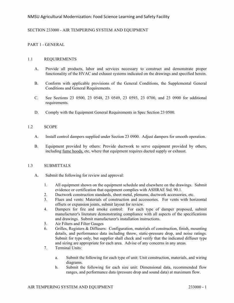
NMSU Agricultural Modernization: Food Science Learning and Safety Facility
AIR TEMPERING SYSTEM AND EQUIPMENT 233000 - 1
SECTION 233000 - AIR TEMPERING SYSTEM AND EQUIPMENT
PART 1 - GENERAL
1.1 REQUIREMENTS
A. Provide all products, labor and services necessary to construct and demonstrate proper functionality of the HVAC and exhaust systems indicated on the drawings and specified herein.
B. Conform with applicable provisions of the General Conditions, the Supplemental General Conditions and General Requirements.
C. See Sections 23 0500, 23 0548, 23 0549, 23 0593, 23 0700, and 23 0900 for additional requirements.
D. Comply with the Equipment General Requirements in Spec Section 23 0500.
1.2 SCOPE
A. Install control dampers supplied under Section 23 0900. Adjust dampers for smooth operation.
B. Equipment provided by others: Provide ductwork to serve equipment provided by others, including fume hoods, etc, where that equipment requires ducted supply or exhaust.
1.3 SUBMITTALS
A. Submit the following for review and approval:
1. All equipment shown on the equipment schedule and elsewhere on the drawings. Submit evidence or certification that equipment complies with ASHRAE Std. 90.1.
2. Ductwork construction standards, sheet metal, plenums, ductwork accessories, etc.3. Flues and vents: Materials of construction and accessories. For vents with horizontal
offsets or expansion joints, submit layout for review.4. Dampers for fire and smoke control: For each type of damper proposed, submit
manufacturer's literature demonstrating compliance with all aspects of the specifications and drawings. Submit manufacturer's installation instructions.
5. Air Filters and Filter Gauges6. Grilles, Registers & Diffusers: Configuration, materials of construction, finish, mounting
details, and performance data including throw, static-pressure drop, and noise ratings. Submit for type only, but supplier shall check and verify that the indicated diffuser type and sizing are appropriate for each area. Advise of any concerns in any areas.
7. Terminal Units:
a. Submit the following for each type of unit: Unit construction, materials, and wiring diagrams.
b. Submit the following for each size unit: Dimensional data, recommended flow ranges, and performance data (pressure drop and sound data) at maximum flow.
NMSU Agricultural Modernization: Food Science Learning and Safety Facility
AIR TEMPERING SYSTEM AND EQUIPMENT 233000 - 2
c. Submit a schedule showing the following for each terminal unit indicated on the drawings: Tag number, max & min CFM, size, pressure drop, and heating system performance.
8. Layouts of systems covered by this section of the specifications. Layouts shall be at a scale appropriate for the areas shown. Include large scale sections as appropriate.
1.4 QUALITY ASSURANCE
A. Comply with the following codes & standards:
1. UMC 2006 Chapter 6 – Duct Systems2. UMC 2006 Standard 6-2, Standard for Metal Ducts3. SMACNA 2005 HVAC Duct Construction Standards – Metal and Flexible, including
Addendums4. SMACNA Round Industrial Duct Construction Standards – 19995. SMACNA Rectangular Industrial Duct Construction Standards – 2004 6. NFPA-90A-2002 - Standard for the Installation of Air-Conditioning and Ventilating
Systems
B. Component Characteristics
1. All components within ducts and plenums shall be non-combustible or shall have a flame spread less than 25 and smoke developed less than 50 when tested as a composite product per NFPA 255, ASTM E84, or UL 723, except where specifically permitted by the UMC and noted in the drawings or specs.
1.5 SOUND LEVELS
A. Sound levels attributable to mechanical equipment are designed to result in sound levels of NC 40 for offices, conference rooms, and NC 35 for classrooms, etc., measured within the rooms. Mechanical equipment that has been substituted for the specified equipment shall perform within the specified equipment sound limitations, or will be replaced or adjusted as required. Sound levels attributable to duct vibration that result in noticeable noise or vibration to duct hangers, lighting fixtures, ceiling tees or diffusers shall be re-supported or adjusted until the disturbing noise is brought within acceptable limits.
1.6 DIMENSIONS
A. Compare all drawings and verify all dimensions both on the drawings and in the field before laying-out, cutting, and fabricating the work.
B. Refer to Section 23 0500, Common Work Requirements for HVAC, for coordination drawing requirements.
NMSU Agricultural Modernization: Food Science Learning and Safety Facility
AIR TEMPERING SYSTEM AND EQUIPMENT 233000 - 3
PART 2 - PRODUCTS
2.1 DUCTWORK AND PLENUMS
A. Materials: Construct all ducts, casings, plenums etc. from galvanized steel sheets except as indicated. Sheets shall be free of blisters, slivers, pits, and imperfectly galvanized spots. Reinforcing angles and bars, and duct support materials shall be same material as ductwork if exposed to the air stream, or galvanized steel if not exposed to the air stream.
1. Galvanized Steel: Per ASTM A653/A653-03 Standard Specification for Steel Sheet,
Zinc-Coat (Galvanized) or Zinc-Iron Alloy-Coat (Galvanized) by the Hot Dip Process, with minimum 1.25oz/sf zinc.
2. Aluminum: Alloy 3003-H143. Stainless Steel: 340SS, provide No. 2B finish in exposed areas4. Fiberglass Ductwork (Ductboard): Use only where specifically noted. Minimum 1-inch
thick, 3 lb. density rigid fiberglass ductboard with glass fiber reinforced vapor barrier, UL Class 1, labeled on each board per UMC-06 Standard 6-5.
a. Properties:
1) Thermal conductivity for 1-inch thickness shall not exceed 0.22 Btuh/SF-F at 75 deg F
2) Noise reduction coefficient of 0.80 on Mounting No. 6.
b. Tape: 3-inch "Hardcast" mineral impregnated woven fiber tape with an actuator/adhesive applied in accordance with the manufacturer's directions, or thermlok heat sensitive tapes. Pressure sensitive tapes will not be accepted.
c. Owens-Corning Fiberglass, Johns Manville, Certain-Teed or equivalent. Flexural rigidity (E.I.) average shall not be less than 475.
5. Polyvinyl Coated Galvanized Steel: Minimum 4 mil polyvinyl coating. Foremost Manufacturing Company, Southfield, Michigan. Model PCD 4 by 1 for exterior coating only, or Model PCD 4 by 4 for both interior and exterior coating.
B. Double-Wall Round, Rectangular, and Oval Ducts and Fittings.
1. Provide Double Wall Ducts as noted on the plans: Fabricate ducts with indicated dimensions for clear internal dimensions of the inner duct.
2. Outer Duct: Comply with SMACNA's "HVAC Duct Construction Standards - Metal and Flexible" based on indicated static-pressure class unless otherwise indicated.
3. Transverse Joints: Select joint types and fabricate in accordance with SMACNA's "HVAC Duct Construction Standards - Metal and Flexible," Figure 2-1, "Rectangular Duct/Transverse Joints," for static-pressure class, applicable sealing requirements, materials involved, duct-support intervals, and other provisions in SMACNA's "HVAC Duct Construction Standards - Metal and Flexible."
4. Longitudinal Seams: Select seam types and fabricate in accordance with SMACNA's "HVAC Duct Construction Standards - Metal and Flexible," Figure 2-2, "Rectangular Duct/Longitudinal Seams," for static-pressure class, applicable sealing requirements, materials involved, duct-support intervals, and other provisions in SMACNA's "HVAC Duct Construction Standards - Metal and Flexible." All longitudinal seams shall be
NMSU Agricultural Modernization: Food Science Learning and Safety Facility
AIR TEMPERING SYSTEM AND EQUIPMENT 233000 - 4
Pittsburgh lock seams unless otherwise specified for specific application.5. Interstitial Insulation: Fibrous-glass liner complying with ASTM C 1071, NFPA 90A, or
NFPA 90B; and with NAIMA AH124, "Fibrous Glass Duct Liner Standard."
a. Maximum Thermal Conductivity: 0.27 Btu x in./h x sq. ft. x deg F at 75 deg F mean temperature.
b. Install spacers that position the inner duct at uniform distance from outer duct without compressing insulation.
c. Coat insulation with antimicrobial coating.d. Retain subparagraph below for additional protection of airstream.e. Cover insulation with polyester film complying with UL 181, Class 1.
6. Inner Duct: Minimum 24-gauge solid galvanized sheet steel.
C. Flexible Ducts: Factory fabricated, listed as a Class 1 Air Duct per UL 181 with aluminum foil interior liner, corrosion resistant helix mechanically locked to fabric to ensure dimensional stability, helix separated from air stream, R-5 fiberglass insulation, and metalized outer vapor barrier. Ducts shall be rated at 10-inch positive pressure, 5-inch negative pressure, 0.1 perm per ASTM E96, and -20 to +250oF. Flexmaster Type 3M, Thermaflex M-KC, OAE.
D. Ductwork Accessories
1. Sealers: Water based, for use on galvanized steel and with the other materials specified
herein, suitable for use at -20 to +200oF and duct pressures to 10 inches wg, dry to the touch within 12 hours, sufficiently flexible to pass a 0.25-inch mandrel test, listed per UL-181A & 181B, and suitable for storage and application at 40–110oF. Approved Manufacturers: Carlisle Coatings & Waterproofing “Hardcast,” Foster, RCD, AM Conservation Group, OAE.
2. Tapes: 4” woven cotton fiber impregnated with mineral gypsum and modified acrylic/silicone activator to react exothermically with tape to form hard, durable, airtight seal. Water, mold, and mildew resistant for indoor and outdoor service. Sealant shall be modified styrene acrylic.
2.2 SHEET METAL ACCESSORIES
A. Dampers: Factory fabricated, suitable for use with air at -20 to +240oF, galvanized steel housing and blades except as noted, rated for indicated pressures in either direction and performance rated per AMCA-500.
1. Shafts: Square or hexagonal steel, 3/8-inch or 1/2-inch, continuous through damper, mechanically fastened to damper blade, and extending through frame as required for actuator or standoff bracket and locking quadrant as required by table below.
2. Bearings: Provide for each side of each shaft, molded synthetic or stainless steel sleeve type.
3. Multi-blade dampers: Except as indicated, provide parallel-blade for 2-position applications and opposed blade for modulating applications. Provide jackshafts as required to drive large dampers.
4. Air pressure drop shall not exceed:
a. Dampers rated at 1500 FPM: ____ in wg at 1500 FPM
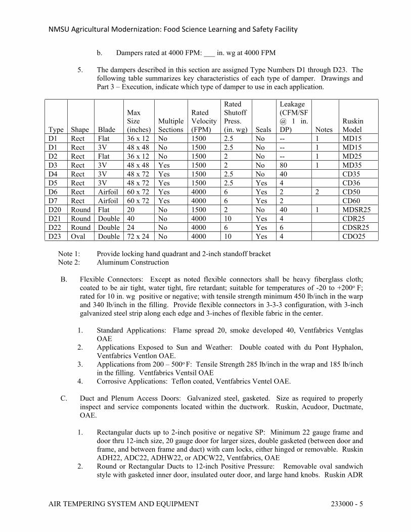
NMSU Agricultural Modernization: Food Science Learning and Safety Facility
AIR TEMPERING SYSTEM AND EQUIPMENT 233000 - 5
b. Dampers rated at 4000 FPM: ___ in. wg at 4000 FPM
5. The dampers described in this section are assigned Type Numbers D1 through D23. The following table summarizes key characteristics of each type of damper. Drawings and Part 3 – Execution, indicate which type of damper to use in each application.
Type Shape Blade
Max Size (inches)
Multiple Sections
Rated Velocity (FPM)
Rated Shutoff Press. (in. wg) Seals
Leakage (CFM/SF @ 1 in. DP) Notes
Ruskin Model
D1 Rect Flat 36 x 12 No 1500 2.5 No -- 1 MD15D1 Rect 3V 48 x 48 No 1500 2.5 No -- 1 MD15D2 Rect Flat 36 x 12 No 1500 2 No -- 1 MD25D3 Rect 3V 48 x 48 Yes 1500 2 No 80 1 MD35D4 Rect 3V 48 x 72 Yes 1500 2.5 No 40 CD35D5 Rect 3V 48 x 72 Yes 1500 2.5 Yes 4 CD36D6 Rect Airfoil 60 x 72 Yes 4000 6 Yes 2 2 CD50D7 Rect Airfoil 60 x 72 Yes 4000 6 Yes 2 CD60D20 Round Flat 20 No 1500 2 No 40 1 MDSR25D21 Round Double 40 No 4000 10 Yes 4 CDR25D22 Round Double 24 No 4000 6 Yes 6 CDSR25D23 Oval Double 72 x 24 No 4000 10 Yes 4 CDO25
Note 1: Provide locking hand quadrant and 2-inch standoff bracketNote 2: Aluminum Construction
B. Flexible Connectors: Except as noted flexible connectors shall be heavy fiberglass cloth; coated to be air tight, water tight, fire retardant; suitable for temperatures of -20 to +200o F; rated for 10 in. wg positive or negative; with tensile strength minimum 450 lb/inch in the warp and 340 lb/inch in the filling. Provide flexible connectors in 3-3-3 configuration, with 3-inch galvanized steel strip along each edge and 3-inches of flexible fabric in the center.
1. Standard Applications: Flame spread 20, smoke developed 40, Ventfabrics Ventglas OAE
2. Applications Exposed to Sun and Weather: Double coated with du Pont Hyphalon, Ventfabrics Ventlon OAE.
3. Applications from 200 – 500o F: Tensile Strength 285 lb/inch in the wrap and 185 lb/inch in the filling. Ventfabrics Ventsil OAE
4. Corrosive Applications: Teflon coated, Ventfabrics Ventel OAE.
C. Duct and Plenum Access Doors: Galvanized steel, gasketed. Size as required to properly inspect and service components located within the ductwork. Ruskin, Acudoor, Ductmate, OAE.
1. Rectangular ducts up to 2-inch positive or negative SP: Minimum 22 gauge frame and door thru 12-inch size, 20 gauge door for larger sizes, double gasketed (between door and frame, and between frame and duct) with cam locks, either hinged or removable. Ruskin ADH22, ADC22, ADHW22, or ADCW22, Ventfabrics, OAE
2. Round or Rectangular Ducts to 12-inch Positive Pressure: Removable oval sandwich style with gasketed inner door, insulated outer door, and large hand knobs. Ruskin ADR
NMSU Agricultural Modernization: Food Science Learning and Safety Facility
AIR TEMPERING SYSTEM AND EQUIPMENT 233000 - 6
and ADF.3. Ducts to 12-inch Negative Pressure: Ruskin ADHP-3.4. Plenum Access Doors: Factory fabricated frame and door rated to 4-inch positive or 8-
inch negative pressure. Provide mill finish and neoprene seals to limit leakage to less than 0.1 CFM/inch perimeter with door closed. Doors shall open against air pressure.
a. Frame: Extruded aluminum with 1.5-inch flange and mitered cornersb. Door: Extruded aluminum mitered frame, double wall 24-gauge galvanized steel
panel with minimum R-5 insulation isolated from the air stream, full-length piano hinge and two heavy-duty latches similar to Ventlok 310.
c. Approved Manufacturers: Ruskin GPAD or approved equal.
D. Turning Vanes:
1. Single wall: Per SMACNA HVAC Duct Construction Standards Figure 2-3 & 2-4.2. Double wall: Airfoil shape with smoothly rounded entry nose and extended trailing edge,
minimum 2” x 3” vane crossection, hot dipped galvanized steel, 26-gauge vanes, 24-gauge runner, each vane double pinned to each runner, field adjustable to required elbow aspect ratio. Performance shall not exceed the following for a 24 x 24 elbow at 2000 FPM average: Air pressure drop 0.105 in. wg; aound generated 54 dB re 10^-12 watts. Aero/Dyne Co. Model HEP, Airsan, Elgen, or equivalent.
E. Roof Curbs and Equipment Support Rails: Factory fabricated, minimum 12-inch high, galvanized steel, configured to account for roof pitch where pitch exceeds 1/4-inch/ft or where required by manufacturer of supported equipment. Coordinate with roofer and provide cant and step if needed to match roof construction.
1. Roof Curbs: 1.5-inch fiberglass insulation with nominal 2" x 2" wood nailer. Provide damper tray where a damper is indicated. Thycurb TC, Greenheck, OAE.
2. Equipment Support Rails: Nominal 2" x 4" wood nailer. Thycurb TEMS, Greenheck OAE
F. Louvers: 4-inch extruded 6063-T5 aluminum alloy frame and blades with flange, mill finish, and 1/2-inch galvanized steel bird screen.
1. Structural: Designed and furnished to carry wind load of not less than 20 psf. Intermediate mullions and supports if provided as part of louver, shall not be visible from the exterior.
2. Air Pressure Drop: Less than 0.20 in wg at 1000 FPM over free area (8.58 square feet), intake or exhaust per AMCA 500 based on 48 x 48 test sample.
3. Moisture Penetration: Less than 0.01 oz/sf over 15 minute test per AMCA-500 at 873 FPM intake over free area based on 48 x 48 test sample.
4. Ruskin ELF375DX OAE.
G. Acoustic Louvers
1. Ruskin ACL 1245, 12 inches deep, with 45 degree blade angle, 22 percent free area (48" x 48" typical unit with .15 inch w.g. maximum pressure drop, at 4277 cfm air flow). Frame and blade material shall be galvanized steel. Free field noise reduction shall be:
Band Frequency (Hz) 63 125 250 500 1000 2000 4000 8000
NMSU Agricultural Modernization: Food Science Learning and Safety Facility
AIR TEMPERING SYSTEM AND EQUIPMENT 233000 - 7
Reduction (db) 14 13 15 20 23 22 20 20
2. Provide bird-screen, steel channel frame, Ruskatherm blanket insulation, and perforated steel interior surface that covers insulation.
H. Thermometers: As specified in Section 23 0505.
I. Barometric Pressure Balance Dampers: Air Balance, Inc. units with adjustable counter weight, aluminum air foil design blades, nylon bearings. Match frame assembly to wall or duct.
2.3 FLUES AND VENTS FOR FUEL-FIRED EQUIPMENT
A. General: Factory-built metallic vent system, UL Listed components. Each component shall bear indication of its UL listing.
1. Heat Resistant Paint: Glidden, Metallite OAE.2. Approved Vent Manufacturers: Metal Fab, Metalbestos, Schebler, Ampco, OAE.
B. Type B Vent: Listed per UL 441 for use with UL Listed Category I (gas or propane fired,
negative pressure, non-condensing) appliances to 530o F, round or flat oval as indicated, double wall with aluminum alloy inner wall, galvanized steel outer wall, both walls hemmed to eliminate sharp edges, minimum 1/4-inch air space for sizes 6-inches and smaller and minimum 1/2-inch air space for sizes 7-inches and larger, with guides to maintain air space. Provide UL Listed vent cap. Metal Fab Type M.
1. Barometric Draft Regulator: UL Listed, double acting type. C. Type III Vent: For use with Category III appliances or other positive pressure, non-condensing
appliances including oil-fired or solid-fuel equipment not exceeding 1200o F exhaust temperature. Listed per UL-103 for use with gas, liquid or solid fuels per NFPA-211 which produce gases up to 1400o F continuously and 1800oF intermittently. Double wall with spacers to maintain alignment, rated for 10-inch clearance to combustibles, 4-inch clearance to noncombustibles, and zero clearance to fire-rated or non-combustible chase.
1. Inner Pipe: Connected with V-bands of same material as inner pipe, and sealed with silicone sealant appropriate for the exhaust gas temperature. Pressure tight to 60 inches water.
2. Outer Pipe: Seal with V-band of same material as outer pipe. Provide silicone sealant for portions exposed outdoors.
3. Expansion Joints: Bellows type.4. Options and Accessories:
a. Inner Wall: 304 SS.b. Outer Wall: Aluminized steel.c. 12-year warranty against defects in materials and workmanship
D. Type IV Vent: For use with Category II or Category IV appliances (natural gas or propane-fired, positive or negative pressure, condensing, not exceeding 550o F exhaust temperature). Listed per UL-1738, double wall with 1-inch clearance and spacers to maintain alignment.
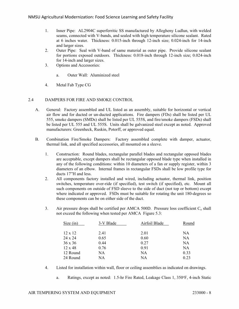
NMSU Agricultural Modernization: Food Science Learning and Safety Facility
AIR TEMPERING SYSTEM AND EQUIPMENT 233000 - 8
1. Inner Pipe: AL2904C superferritic SS manufactured by Allegheny Ludlun, with welded seams, connected with V-bands, and sealed with high temperature silicone sealant. Rated at 6 inches water. Thickness: 0.015-inch through 12-inch size; 0.024-inch for 14-inch and larger sizes.
2. Outer Pipe: Seal with V-band of same material as outer pipe. Provide silicone sealant for portions exposed outdoors. Thickness: 0.018-inch through 12-inch size; 0.024-inch for 14-inch and larger sizes.
3. Options and Accessories:
a. Outer Wall: Aluminized steel
4. Metal Fab Type CG
2.4 DAMPERS FOR FIRE AND SMOKE CONTROL
A. General: Factory assembled and UL listed as an assembly, suitable for horizontal or vertical air flow and for ducted or un-ducted applications. Fire dampers (FDs) shall be listed per UL 555, smoke dampers (SMDs) shall be listed per UL 555S, and fire/smoke dampers (FSDs) shall be listed per UL 555 and UL 555S. Units shall be galvanized steel except as noted. Approved manufacturers: Greenheck, Ruskin, Potorff, or approved equal.
B. Combination Fire/Smoke Dampers: Factory assembled complete with damper, actuator, thermal link, and all specified accessories, all mounted on a sleeve.
1. Construction: Round blades, rectangular parallel blades and rectangular opposed blades are acceptable, except dampers shall be rectangular opposed blade type when installed in any of the following conditions: within 10 diameters of a fan or supply register, within 3 diameters of an elbow. Internal frames in rectangular FSDs shall be low profile type for ducts 17”H and less.
2. All components factory installed and wired, including actuator, thermal link, position switches, temperature over-ride (if specified), test switch (if specified), etc. Mount all such components on outside of FSD sleeve to the side of duct (not top or bottom) except where indicated or approved. FSDs must be suitable for rotating the unit 180-degrees so these components can be on either side of the duct.
3. Air pressure drops shall be certified per AMCA 500D. Pressure loss coefficient Co shall not exceed the following when tested per AMCA Figure 5.3:
Size (in) 3-V Blade Airfoil Blade Round
12 x 12 2.41 2.01 NA24 x 24 0.65 0.60 NA36 x 36 0.44 0.27 NA12 x 48 0.76 0.91 NA12 Round NA NA 0.3324 Round NA NA 0.23
4. Listed for installation within wall, floor or ceiling assemblies as indicated on drawings.
a. Ratings, except as noted: 1.5-hr Fire Rated, Leakage Class 1, 350oF, 4-inch Static
NMSU Agricultural Modernization: Food Science Learning and Safety Facility
AIR TEMPERING SYSTEM AND EQUIPMENT 233000 - 9
Pressure, Dynamic. 1) Up to 1600 FPM: Greenheck FSD-211 (3-V blade type), OFSD-211, or
FSDR-511 (round).2) Up to 3000 FPM: Greenheck FSD-311 or 311V (airfoil blade) or OFSD-
311.
b. 3-Hr Rated Walls: Greenheck FSD-231.c. Stainless Steel: Greenheck SSFSD-211 or SSFSDR-511 (round).
5. Actuators: Electric 2-position, 115/1/60 (provide factory wired transformer if required), normally closed, spring return, NEMA-1 except as noted. Actuator shall fully re-open damper when power is restored after any power interruption.
6. Accessories
a. Transitions: Provide round-to-rectangular, oval-to-rectangular, or rectangular-to-rectangular transitions as appropriate for the application.
b. Thermal Link: Provide re-settable bi-metallic thermal link to initiate closure when the air temperature within the duct rises to 165o F. Where indicated provide thermal links for operation at 212o F, 250o F, or 350o F. Thermal link shall be easily resettable from outside the duct.
c. Position Switches: Provide dry contacts for remote monitoring of damper open and closed positions.
d. Retaining plates and angles: Provide as required. Galvanized steel specifically designed for the particular FSD and included as part of the UL Listed assembly.
e. Installation decals: Provide installation decals on the sleeve which give the installer clear installation instructions.
f. Temperature Override Control: Provide controls so that the thermal link can be over-ridden and the FSD opened for smoke control, even if the air temperature exceeds the setting of the thermal link, provided the temperature does not exceed 350o F.
C. Smoke dampers: Similar to fire/smoke dampers noted above, except as follows:
1. Smoke dampers shall comply with UL 555S, but need not comply with UL 555.2. Smoke dampers need not have a fire rating.3. The thermal link and temperature override are not applicable.4. Suitable for installation within a wall, floor or ceiling assemblies as indicated.
a. Ratings, except as noted: Leakage Class 1, 350o F, 4-inch Static Pressure, Dynamic.
1) Up to 1600 FPM: Greenheck SMD-201 (3-V blade type) or SMDR-501 (round).
2) Up to 3000 FPM: Greenheck SMD-301, 301V (airfoil blade) or SMDR-401.
b. 6-inch pressure rated: Similar to Greenheck SMD-401c. Stainless Steel: SSSMD-201 & SSSMDR-501 (round).
D. Fire Dampers: Dynamic rated, suitable for closing against 8-inch differential pressure. Curtain type with sleeve and 165oF replaceable fusible link, resettable. Provide round-to-rectangular,
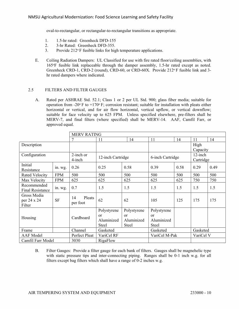
NMSU Agricultural Modernization: Food Science Learning and Safety Facility
AIR TEMPERING SYSTEM AND EQUIPMENT 233000 - 10
oval-to-rectangular, or rectangular-to-rectangular transitions as appropriate.
1. 1.5-hr rated: Greenheck DFD-1552. 3-hr Rated: Greenheck DFD-355.3. Provide 212o F fusible links for high temperature applications.
E. Ceiling Radiation Dampers: UL Classified for use with fire rated floor/ceiling assemblies, with 165oF fusible link replaceable through the damper assembly, 1.5-hr rated except as noted. Greenheck CRD-1, CRD-2 (round), CRD-60, or CRD-60X. Provide 212o F fusible link and 3-hr rated dampers where indicated.
2.5 FILTERS AND FILTER GAUGES
A. Rated per ASHRAE Std. 52.1; Class 1 or 2 per UL Std. 900; glass fiber media; suitable for operation from -20o F to +170o F; corrosion resistant; suitable for installation with pleats either horizontal or vertical, and for air flow horizontal, vertical upflow, or vertical downflow; suitable for face velocity up to 625 FPM. Unless specified elsewhere, pre-filters shall be MERV-7, and final filters (where specified) shall be MERV-14. AAF, Camfil Farr, or approved equal.
MERV RATING7 11 14 11 14 11 14
Description HighCapacity
Configuration 2-inch or4-inch 12-inch Cartridge 6-inch Cartridge 12-inch
CartridgeInitialResistance in. wg. 0.26 0.25 0.58 0.39 0.58 0.29 0.49
Rated Velocity FPM 500 500 500 500 500 500 500Max Velocity FPM 625 625 625 625 625 750 750RecommendedFinal Resistance in. wg. 0.7 1.5 1.5 1.5 1.5 1.5 1.5
Gross Mediaper 24 x 24Filter
SF 14 Pleats per foot 62 62 105 125 175 175
Housing Cardboard
PolystyreneorAluminizedSteel
PolystyreneorAluminizedSteel
PolystyreneorAluminizedSteel
Frame Channel Gasketed Gasketed GasketedAAF Model Perfect Pleat VariCel RF VariCel M-Pak VariCel VCamfil Farr Model 3030 RigaFlow
B. Filter Gauges: Provide a filter gauge for each bank of filters. Gauges shall be magnehelic type with static pressure tips and inter-connecting piping. Ranges shall be 0-1 inch w.g. for all filters except bag filters which shall have a range of 0-2 inches w.g.
NMSU Agricultural Modernization: Food Science Learning and Safety Facility
AIR TEMPERING SYSTEM AND EQUIPMENT 233000 - 11
2.6 TERMINAL UNITS
A. General: Factory packaged unit with casing, air valve, air flow sensor. If the following sections are specified or required, provide them as part of the factory package: heating section, fan, and sound attenuator. Terminal units (TUs) shall be suitable for variable volume operation over the scheduled air flow ranges. Air flow and sound performance shall be rated per ARI 880. All materials in the air stream shall comply with the requiements of UL-181 and NFPA-90A.
1. Unit Construction:
a. Casing: Minimum 22-gauge galvanized steel with round inlet collar, rectangular outlet collar, 3/4-inch acoustic lining with cut edges coated with sealant.
1) Provide aluminum foil liner over acoustic lining in casing and all accessory sections (e.g., sound attenuator). Liner shall comply with:
a) UL 181 – Air Erosion, Mold Growth & Humidityb) UL 723 – 25/50 flame & smokec) ASTM E84 – 25/50 flame & smoked) ASTM C665 – Fungi Resistance
b. Air Valve: Heavy gauge metal damper, shaft to extend through casing, self-lubricating bearing, with leakage not to exceed 2% of rated air flow when closed with 3-inch inlet pressure.
c. Air Flow Sensor: Cross configuration located at inlet of assembly, accurate to within 5% with 90o elbow directly at inlet connection. Provide
d. Sound Attenuator: Galvanized steel with acoustic lining. Provide aluminum liner if specified for casing.
e. Heating Section:
1) HW Coils: Copper tubes, aluminum fins, galvanized steel casing, sweat connections, ARI rated, minimum 300 psi rated. Size heating coils for the capacities indicated on the equipment schedule. Provide single row coils wherever they can do the specified heating duty. Provide 2-row coils where indicated and where required for the indicated heating capacity. Do not exceed 0.5-inch static pressure drop for the entire unit (terminal unit, heating coil and sound attenuator). Where necessary to limit pressure drop, either over-size unit or provide a separate, larger (lower pressure drop) heating coil to be installed in the discharge ductwork.
2) Electric Heaters: Factory installed and wired with all necessary safety controls, UL listed as an assembly, with galvanized steel enclosure, 80/20 nickel chrome heater elements, electronic modulating control with 4-20 mA input signal from DDC system, air flow switch, access door with door interlock disconnect switch, automatic reset primary thermal cutout switch, manual reset secondary thermal cutout, 24-V control transformer, NEMA-1 enclosure for all electrical components with hinged access door with wiring diagram. Controller shall be solid state type to minimize electrical interference and for silent operation.
2. Sound Data: The equipment schedules show maximum allowable NC levels based on
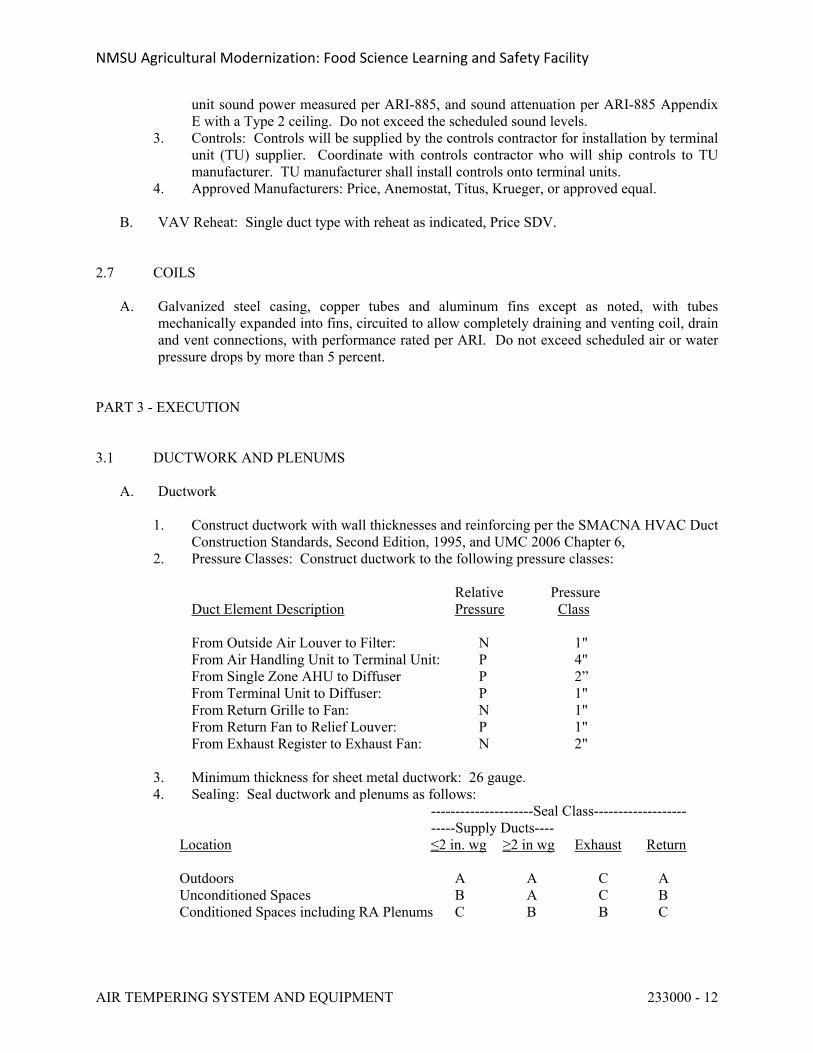
NMSU Agricultural Modernization: Food Science Learning and Safety Facility
AIR TEMPERING SYSTEM AND EQUIPMENT 233000 - 12
unit sound power measured per ARI-885, and sound attenuation per ARI-885 Appendix E with a Type 2 ceiling. Do not exceed the scheduled sound levels.
3. Controls: Controls will be supplied by the controls contractor for installation by terminal unit (TU) supplier. Coordinate with controls contractor who will ship controls to TU manufacturer. TU manufacturer shall install controls onto terminal units.
4. Approved Manufacturers: Price, Anemostat, Titus, Krueger, or approved equal. B. VAV Reheat: Single duct type with reheat as indicated, Price SDV.
2.7 COILS
A. Galvanized steel casing, copper tubes and aluminum fins except as noted, with tubes mechanically expanded into fins, circuited to allow completely draining and venting coil, drain and vent connections, with performance rated per ARI. Do not exceed scheduled air or water pressure drops by more than 5 percent.
PART 3 - EXECUTION
3.1 DUCTWORK AND PLENUMS
A. Ductwork
1. Construct ductwork with wall thicknesses and reinforcing per the SMACNA HVAC Duct Construction Standards, Second Edition, 1995, and UMC 2006 Chapter 6,
2. Pressure Classes: Construct ductwork to the following pressure classes:
Relative PressureDuct Element Description Pressure Class
From Outside Air Louver to Filter: N 1"From Air Handling Unit to Terminal Unit: P 4"From Single Zone AHU to Diffuser P 2”From Terminal Unit to Diffuser: P 1"From Return Grille to Fan: N 1"From Return Fan to Relief Louver: P 1"From Exhaust Register to Exhaust Fan: N 2"
3. Minimum thickness for sheet metal ductwork: 26 gauge.4. Sealing: Seal ductwork and plenums as follows:
---------------------Seal Class------------------------Supply Ducts----
Location ≤2 in. wg ≥2 in wg Exhaust Return
Outdoors A A C AUnconditioned Spaces B A C BConditioned Spaces including RA Plenums C B B C
NMSU Agricultural Modernization: Food Science Learning and Safety Facility
AIR TEMPERING SYSTEM AND EQUIPMENT 233000 - 13
Seal Class Description .
A All transverse joint, longitudinal seams and duct wall penetrations.B All transverse joints and longitudinal seams.C Transverse joints
a. Apply duct sealer to inside of seams and joints. Do not use pressure sensitive tape as the primary sealant.
5. Clearance to earth: Maintain minimum 4-inch separation between ductwork insulation
and earth.6. Openings in Ductwork: During installation protect the open ends of ducts to prevent
debris and dirt from entering. 7. Provide turning vanes in square elbows of low velocity supply and exhaust ductwork. 8. Collars: Where exposed ducts pass through walls, floors, or ceilings, provide a tight-
fitting, flanged sheetmetal collar around duct and tight against finished surface to cover opening and present a neat appearance. Lock collar to duct.
9. Cross Breaking: Cross-break low velocity rectangular sheetmetal ducts on all four sides. Cross break sheet metal between standing seams or reinforcing angles. The center of cross break shall be of the required height to assure surfaces being rigid. Do not cross-break high velocity plenum panels.
10. Grilles Registers and Diffusers: Install plumb, affix to general construction as appropriate, make air-tight connection to ductwork, and adjust air flow pattern to achieve appropriate velocities in the occupied zones. Request direction from Engineer if any question exists regarding proper air flow adjustment.
11. Duct Thermometers: Provide thermometers to indicate mixed air, outside air, and supply air of indoor air handling units over 2,500 cfm and where shown on the Drawings.
12. Test Holes: Provide test holes in ducts at locations where testing is required per Section 23 0593 and as requested by the T&B agent. Close test holes with rubber plugs. Reseal all insulated ductwork with the same insulation, jacket and vapor barrier material after T&B is complete.
13. Closure Systems:
a. Rigid Air Ducts: Comply with UL 181A – Standard for Closure Systems for Use with Rigid Air Ducts and Air Connectors.
b. Flexible Air Ducts: Comply with UL 181B – Standard for Closure Systems for Use with Flexible Air Ducts and Air Connectors.
14. Factory Made Air Ducts: Install in accordance with the terms of their listing and the manufacturer’s recommendations.
15. Acoustic Insulation: See Section 23 0700, HVAC Insulation. Fabricate ductwork so the dimensions indicated on the drawings are the clear dimensions for air flow inside the acoustic insulation.
16. Coordination with Building Construction
a. General: The drawings show the general intended configuration of the ductwork. Provide additional offsets where necessary to coordinate with the building construction or with the work of other disciplines. Transition ductwork as required at no change in contract price. Where this is necessary, submit for review and maintain the indicated flow areas.
b. Ductwork is frequently routed through bar joists and between bar joists.
NMSU Agricultural Modernization: Food Science Learning and Safety Facility
AIR TEMPERING SYSTEM AND EQUIPMENT 233000 - 14
Coordinate duct locations with joist submittals prior to fabrication.
B. Special Applications
1. Moisture Laden Ductwork: Stainless steel with all joints liquid-tight by continuous external welding. Welds shall be free from pits, runs, spatter and other imperfections. Pitch horizontal ductwork downward to intake opening. Where traps occur that collect water, provide a 1/2-inch half coupling welded to the bottom of the duct and pipe to spill over nearest drain. Include a properly sized trap in the drain piping.
2. Fume Hood Ductwork: Stainless steel with seams and joints continuously welded on the exterior. Spiral lock seam is not acceptable.
3. Shower Room Exhaust Ductwork: Aluminum4. Ducts Handling Corrosive Vapors: Either stainless steel or galvanized steel with internal
polyvinyl coating constructed and sealed as noted.5. Underslab Ductwork: Galvanized steel, polyvinyl coated on the exterior, constructed and
sealed for 2-inch SP, insulated per Section 23 0700, and concrete encased. Concrete thickness shall be as indicated on the drawings, but not less than 2-inch thick.
a. Take care to prevent damaging ductwork when concrete is poured. Work with and provide guidance to the contractors responsible for pouring concrete and responsible for installing the building moisture protection system.
b. Anchor ductwork not more than 4-ft on centers to prevent floating. Use minimum 12-gauge wire or 16-gauge straps. Protect openings in ductwork with wood or metal blocking.
c. Pour concrete in maximum 12-inch lifts with each layer being allowed to set before pouring the next. Do not use power vibrators shall not be used in placement of concrete on or around ducts.
6. Fiberglass Ductwork (Ductboard)
a. Provide fiberglass ductboard only where specifically indicated on the drawings and in this specification.
b. Install per UMC-06 Standard 6-05 – Standard for Installation of Factory-Made Air Ducts and SMACNA Standard 1884-2003 – Fibrous Glass Duct Construction Standard.
c. The drawings indicate required clear inside dimensions for air flow.d. Where a duct constructed of ductboard penetrates a wall or floor which requires a
fire damper, smoke damper, or fire/smoke damper, install the FD, SMD or FSD in the wall per its listing, make sheet metal connections to the damper if required, and then transition back to ductboard.
7. Exterior Ductwork: Install ductwork as specified herein and insulate per Section 23 0700. Then enclose the exposed top and sides of ductwork with 28 gauge galvanized steel or 26-guage aluminum to protect the insulation. Repair any damage to the insulation jacket. Slope sheet metal enclosure to shed water.
C. Hangers and Supports
1. Securely support ducts per SMACNA and UMC Table 6-7. Provide support at each concentrated load and at each change in direction. Provide supports on each side of
NMSU Agricultural Modernization: Food Science Learning and Safety Facility
AIR TEMPERING SYSTEM AND EQUIPMENT 233000 - 15
rectangular ducts and equipment. Where vertical ducts pass through floors or roofs, support with angles or other steel members attached to minimum two opposite sides of duct. Size supports to rigidly support the ductwork. Provide lateral support.
2. Hangers for terminal units: Minimum four 1" x 1/8" galvanized steel straps or two angle trapeze supports.
3. Horizontal Round Ducts: 30 inches and larger in diameter: Provide 2" x 2" x 1/8" black steel rolled angle ring on 6-ft centers, and support from angle.
D. Plenums
1. Single Wall Plenums: Shop fabricated minimum 16 gauge galvanized sheet steel. Horizontal and vertical panels are to be fabricated of 2' x 10' sheets. Unless otherwise dimensioned on the Drawings, access door frames are not to exceed 16-3/4 inch width. Where door width exceeds 16-3/4 inches, vertical panels shall be fabricated around 2" x 2" x 1/4" angle. If the plenum height or width exceeds 9 feet, provide a 2-1/2" x 1/8" continuous galvanized steel strip between each horizontal and vertical seam. Provide high velocity cement at each joint during panel assembly. Panels are to be bolted as shown on the details or tack welded at the Contractor's option; however, enough panels must be bolted to allow removal of equipment from the plenums. Cover interior surfaces with 2-inch thick, acoustical lining.
a. Plenum Access Doors: Minimum two fastening devices that can be operated on either side of the door; these devices to be readily operated and moving parts to have bronze pins. All parts of the door shall be constructed of galvanized iron and shall be airtight. Latches: "Ventlock" No. 310 OAE.
2. Double Wall Plenums: Factory fabricated, Semco or equivalent. Submit shop drawings for review including overall configuration, construction details, access doors, erection drawings and structural calculations stamped by a registered structural engineer,.
a. Factory fabricated, minimum 18 gauge galvanized steel outside, perforated galvanized steel inside, with 2-inch sound insulation between. Plenums downstream of final filters shall have solid inner panel.
b. Heat transfer coefficient shall not exceed 0.0575 BTUH/SF-F at 75 deg F mean temperature. Pressure Ratings: 12 in. wg positive and 10 in. wg negative.
c. Noise attenuation shall be as follows in decibels, re 10-12 watts.
OCTAVE BAND1 2 3 4 5 5 7 8
Attenuation, db: 26 30 36 41 34 36 44 37Noise Absorption Coeff: 0.22 0.39 1.20 1.36 1.03 0.84 0.74 0.68
3.2 DUCTWORK ACCESSORIES
A. Dampers: Install dampers with shafts horizontal. Locate dampers so that actuators are readily accessible. Verify that dampers operate smoothly.
1. Manual Dampers (Balancing Dampers): Damper Types D1 through D23 are all suitable
for use as manual balancing dampers. Provide locking quadrants.2. Automatic Applications: The following damper types may be used for automatic
NMSU Agricultural Modernization: Food Science Learning and Safety Facility
AIR TEMPERING SYSTEM AND EQUIPMENT 233000 - 16
applications: D4, D5, D6, D7, D21, D22 and D23. Provide damper actuators per Section 23 0900.
B. Flexible Connectors: Provide flexible connectors at locations indicated on the drawings and at
the inlet and outlet of each fan directly connected to duct system. Select flexible connectors appropriate for the application. Provide steel spring vibration isolators spanning across flexible connections of isolated fan housings to prevent blow-apart due to horizontal displacement of fan housings.
C. Access Doors: Provide as required for access to all components located within ductwork.
Locate to facilitate access to such components. Size as appropriate. In addition to locations specifically called out on the drawings or elsewhere in these specs, provide access doors at the following: FDs, SMDs, FSDs, instrumentation mounted within ductwork, fan bearings.
D. Turning Vanes: Provide turning vanes in square elbows of all supply ducts. Single wall turning vanes may be used in ducts up to 1500 FPM and 24-inch vane length. Provide double wall turning vanes in ducts exceeding either of these criteria.
E. Roof Curbs and Equipment Support Rails: Coordinate the location of roof curbs and rails with the roof structure, ductwork distribution, and other work. Install after roof deck is installed but before roof is insulated. Mount curbs and rails securely to deck per manufacturer’s recommendations. Provide counterflashing as required.
F. Louvers: Coordinate louver size and construction with structural and architectural openings to assure proper fit. Securely fasten louver to internal structural members to withstand a force of 25 lb/sf plus a safety factor of 3.0.
G. Instrumentation: Install duct thermometers and filter gauges so they are easily readable from the operator level.
3.3 FLUES AND VENTS FOR FUEL-FIRED EQUIPMENT
A. General: Install per the drawings and these specifications, manufacturer’s instructions, the terms of the vent’s UL Listing, the UMC and NFPA-211.
1. Use the same type vent for the entire system from the equipment connection to the termination outside. Provide all fittings, transitions, adapters, supports, storm collars, etc.
2. Install per the venting requirements of the appliance manufacturer. Comply with clearances per UL Listing. Minimize offsets and resistance to flow. System shall develop a positive flow adequate to remove products of combustion to outside. Do not run any portion of the vent system through any supply or return air duct or plenum. Do not connect the vent from any Category I or II (non-positive pressure) appliance with any Category III or IV (positive pressure) appliance. Do not install any manually operated damper at any point in vent system.
3. Properly support the system and make provisions for thermal expansion. Install so as to prevent leakage of flue gases into the building. Provide drain connections where condensate is likely to accumulate, and pipe to spill over floor drain.
4. Provide ventilated thimbles where vents pass through walls, floors and roof. Paint all galvanized or aluminized steel parts exposed to the weather with one coat of corrosion and heat-resistant primer, and one coat of heat resistant paint.
NMSU Agricultural Modernization: Food Science Learning and Safety Facility
AIR TEMPERING SYSTEM AND EQUIPMENT 233000 - 17
5. Terminate low heat appliances as indicated on the drawings, but not less than:
a. 3 ft above the highest point where the vent passes the roof.b. 2 ft above any portion of a building within a horizontal distance of 10 ft.c. 3 ft above any forced air inlet located within 10 ft.
B. Type B: If a draft damper is supplied with the appliance for installation in the flue, install it
per manufacturer’s instructions. If appliance is listed for use with a draft hood but is not supplied with one, provide a properly sized barometric draft regulator immediately in the vent outlet, and install per manufacturer’s recommendations. Pitch vent up minimum 1/4-inch per foot. Join sections per manufacturer’s recommendations using sheet metal screws or proprietary closure system of a UL Listed venting system. Provide vent cap,
C. Type III and IV: Install per the drawings and these specifications, per manufacturer’s instructions, per the terms of the vent’s UL listing, and per NFPA-211.
3.4 DAMPERS FOR FIRE AND SMOKE CONTROL
A. Select FDs, SMDs and FSDs as appropriate to the application. Dampers may be rectangular or round, and single-section or multi-section as required, but shall not be less than the duct sizes indicated on the drawings nor larger than the maximum sizes per the UL listing for a given style of damper. Provide transitions and sleeves as required.
1. FSDs may be used where SMDs are indicated provided they meet the required ratings of the indicated SMDs and provided the FSDs are installed in accordance with their listing.
B. Install dampers in accordance with their listing. Terminate acoustic lining at dampers as necessary to ensure proper damper operation. Install actuators and access doors on the side of the duct unless space conditions preclude this. Provide adequate clearance for proper operation, and minimum 36-inch clearance for servicing actuator.
1. When space conditions preclude installing actuators on the side, such components may be installed on the top or bottom of the duct provided good access to these components is maintained.
2. When size requires the use of multiple dampers, provide framing to ensure the dampers remain in place.
3. Provide a duct access door at each FD, SMD and FSD for inspection and maintenance. Provide minimum 1/2-inch high label, “SMOKE DAMPER,” “FIRE DAMPER,” or “FIRE/SMOKE DAMPER.”
C. Test all SMDs and FSDs after the system is installed to ensure proper operation based on both smoke and fire signals. Advise Owner minimum 2 weeks in advance and invite him to observe these tests. Submit a written report with a table which identifies each such damper (along with plans which indicate each such damper); gives its size, type and model number; the date on which it was tested; the test results; and places for the initials of the person performing test for the contractor and the person witnessing test for owner. Should any dampers fail to operate properly, service them and demonstrate proper operation. Reset all dampers when the testing is complete.
NMSU Agricultural Modernization: Food Science Learning and Safety Facility
AIR TEMPERING SYSTEM AND EQUIPMENT 233000 - 18
3.5 FILTERS AND FILTER GAUGES
A. Provide one set of MERV-7 temporary filters until testing and balancing is complete. Then immediately before the system is turned over to the Owner at the completion of the project, remove these filters and provide the specified filters.
3.6 TERMINAL UNITS
A. Install terminal units so that controls and piping components are readily accessible for normal service and maintenance. Provide minimum 3 ft clear in front of control panels.
3.7 GRILLES REGISTERS AND DIFFUSERS
A. Install grilles, registers & diffusers (GRDs) square with building construction. Mount sidewall GRDs minimum, 3-inches above floor level. If GRDs have provisions to adjust the direction of air flow, submit a written recommendation regarding the best direction for air flows, obtain written approval from the Owner’s Representative, and adjust GRDs accordingly.
B. Verify frame types with architectural RCPs prior to ordering GRDs.
3.8 CLOSEOUT ISSUES
A. Leakage Testing
1. Pressure test not less than 25% of the installed ductwork of each system rated at 3 in wg or more, either positive or negative pressure. Advise Owner’s Representative when systems will be ready for testing. For large systems separate tests may be made on different sections. The Owner’s representative will designate the sections to be tested, but not more than 24 hours in advance of test. Cap ends of ducts as required and provide equipment as required for testing.
2. Measure duct leakage per the SMACNA HVAC Duct Leakage Test manual. Leakage shall not exceed the following:
Lmax = CLP0.65, where Lmax = maximum permitted leakage, cfm/100 sf of duct surface areaCL = Duct leakage class (cfm/100 sf at 1-inch wg) = 6 for rectangular sheet metal, rectangular fiberglass, and round flexible ducts = 3 for round and flat oval sheet metal or fiberglass ductsP = Test pressure. Test pressure shall match system pressure class.
3. If sample is defective, the contractor shall repair or modify the defective section and re-test it to demonstrate compliance. In addition, for each section which fails its original pressure test, the Owner’s Representative will designate an additional ductwork section of similar size, for the Contractor to test. This section will be in addition to 25% area originally planned to be tested. .
4. Complete all leakage testing and repairs prior to concealing ducts.5. Submit a test report that documents the test procedure and results. Include:
NMSU Agricultural Modernization: Food Science Learning and Safety Facility
AIR TEMPERING SYSTEM AND EQUIPMENT 233000 - 19
a. Test equipment – model numbers, technical data, calibration data, etc. b. Drawings showing the extent of the systems tested.c. Test results.d. Dates, witnesses, and signatures of witnesses.
B. Testing and Balancing: Test and balance the complete air tempering system as specified in Section 23 0593. It is anticipated that the TAB effort will identify some system deficiencies. Work in a cooperative manner to identify the cause of these deficiencies. Where deficiencies aer due to defects in installation, or workmanship, repair as required and re-test to demonstrate proper performance.
C. Cleaning
1. All ducts, coils, housing, registers, grilles, fans, etc., shall be clean when installed and shall be kept clean until the system is completed. As the various parts of the system are installed, they shall be wiped or blown clean and openings taped dust-tight with heavy paper or cardboard until the system is completed and ready for testing. At that time all covers and protective wrappings shall be removed. Where one has been torn or previously removed, the duct, coil, register, etc., shall be carefully cleaned of any dirt or dust that has entered the opening.
END OF SECTION 233000
NMSU Agricultural Modernization: Food Science Learning and Safety Facility
LABORATORY EXHAUST FANS 233416 - 1
SECTION 233416 - LABORATORY EXHAUST FANS
PART 1 - GENERAL
1.1 SUMMARY
A. This Section includes the following:
1. Mixed-flow induced dilution fans.
1.2 SUBMITTALS
A. Product Data: Include rated capacities, furnished specialties, and accessories for each type of product indicated.
B. Shop Drawings: Detail equipment assemblies and indicate dimensions, weights, loads, required clearances, method of field assembly, components, and location and size of each field connection.
C. Field quality-control test reports.
D. Operation and maintenance data.
E. Submit shop drawings and product data sheets including performance data, fan performance curves, vibration levels, maintenance requirements and sound power levels.
F. Fan manufacturer shall furnish a certificate of guarantee stating that the fan, mixing plenum, outlet nozzle, acoustical silencer nozzle, stack extension if any, and all related accessories specified herein have been pre-tested at the factory and that the curves supplied in 1.3.1 have been de-rated for any and all system effects created by the accessories.
1.3 QUALITY ASSURANCE
A. Electrical Components, Devices, and Accessories: Listed and labeled as defined in NFPA 70, Article 100, by a testing agency acceptable to authorities having jurisdiction, and marked for intended use.
B. AMCA Compliance: Products shall comply with performance requirements and shall be licensed to use the AMCA-Certified Ratings Seal.
C. NEMA Compliance: Motors and electrical accessories shall comply with NEMA 1.
1.4 WARRANTY
A. Fan manufacturer shall provide a 7 year parts warranty from time of purchase to include fan, plenum, motor and all drive mechanisms including pillow blocks, sheaves, shafts, couplings and
NMSU Agricultural Modernization: Food Science Learning and Safety Facility
LABORATORY EXHAUST FANS 233416 - 2
belts. This warranty shall be held solely by the fan manufacturer. It is unacceptable to extend the warranty of a provided component supplier (i.e. motors, dampers, actuators). All warranty claims shall be the sole responsibility of the fan manufacturer.
PART 2 - PRODUCTS
2.1 FANS
A. General Construction:
1. Performance ratings: Conform to AMCA standard 210, 260 and 300. Fans must be tested in accordance with AMCA 210, 260 and 300 in an AMCA accredited laboratory and certified for air and sound performance. Fan shall be licensed to bear the AMCA ratings seal for air performance (AMCA 210), sound performance (AMCA 300), and induced flow fan for high plume dilution blowers (AMCA 260).
2. Fans shall be UL and CUL listed per UL 705 safety standard.3. Fans shall meet the criteria of NFPA-45.4. Classification for Spark Resistant Construction shall conform to AMCA 99.5. Factory fabricated fan, motor, drive and accessories, listed per latest UL listing with air
flow rated per AMCA 211 and sound rated per latest AMCA test procedure.6. Fan wheel: Statically & dynamically balanced, with shaft sized so first critical speed is
minimum 25% above maximum operating speed.7. Motor and Drive: Premium efficiency ODP motor per Spec Section 23 05 00, direct
drive or belt driven as indicated in schedule on drawings, bearings with 100,000 hr L-10 life.
8. Variable Speed Applications: Provide Class F insulation.9. See Section 23 0548 for Vibration Isolation requirements.
2.2 LABORATORY EXHAUST FANS
General fans serving General Fume hood and General Lab exhaust: Factory fabricated, weatherproof for rooftop installation, with inlet plenum, dual fan or Tri-Fan assembly as shown on drawings, bypass damper and discharge assembly, listed per UL 705. Each assembly shall include bypass damper section for induced air flow to maintain a constant discharge velocity and plume height. Effective stack height in a 10mph wind shall be a minimum of 40 feet
1. Acceptable Manufacturer:
The plans and specifications for the laboratory fume hood exhaust system are based on systems and equipment manufactured by Strobic Air Corporation.
In strict accordance with this specification, alternative laboratory exhaust systems and equipment shall only be considered for approval provided that the equipment be equal in every respect to the operational characteristics, capacities, and intent specified herein. Approval to bid does not relieve the alternate exhaust system supplier from complying with the minimum requirements or intent of this specification.
NMSU Agricultural Modernization: Food Science Learning and Safety Facility
LABORATORY EXHAUST FANS 233416 - 3
The engineer and owner shall be the sole judges of quality and equivalence of equipment, materials, methods, and life cycle cost.
2. Mixed-flow induced dilution fans:
a. Impellers shall be mounted directly to the motor shaft to provide Arrangement 4 Direct Drive. Motors shall be isolated from the primary exhaust air stream and shall be visible and accessible from the fan exterior for inspection and service.
b. Mixed flow impellers shall consist of combination axial/backward curved blades and shall be of welded steel construction. The impellers shall have non-stall and non-overloading performance characteristics with aerodynamically stable operation at any point on the fan curves.
c. Fan Performance shall be as stated on the schedule. The Static Pressure stated on the schedule shall be at the inlet to the “Fan System” and does not include any losses of equipment provided by the fan manufacturer (ie: HRU, Filters, Silencers, etc…). All losses for the equipment provided by the fan manufacturer shall be detailed in the fan manufacturers technical proposal and or submittal.
d. Fan and all drive components shall have a combined bearing life of a minimum of L10 = 150,000 hours.
e. Maintenance shall only be required on a minimum of 18 month intervals. This maintenance shall be limited to re-greasing of the motor bearings.
f. Fan dynamic balance not to exceed 0.5 mil, peak-to-peak for nominal 900RPM, 1200RPM, and 1800RPM fans, or 0.055 in/sec -peak for 1800 RPM, 0.035 in/sec — peak for 1200 RPM, and 0.030 in/sec-peak for 900 RPM fans measured at the blade pass area when operating at fan frequency. Vibration isolation shall be limited to rubber-in-shear pad type isolators unless otherwise specified.
g. Factory test reports detailing vibration levels at the blade pass area shall be provided. Vibration levels shall be reported in both the axial and radial direction. If fan vibration is greater than 0.5 mils peak-to-peak at the blade pass area, fan manufacturer shall be responsible for providing vibration isolators on each fan and flexible connection at each duct inlet. Manufacturer shall add 0.5" additional static pressure to the fan system to compensate for losses through the flexible connection. Vibration isolators, 2” deflection seismic rated spring, must be installed on each individual fan with a minimum of four per fan. In addition, fan manufacturer shall be responsible for providing a method to repair or replace flexible connection or vibration isolators without shut down of the fan system. This includes any engineering, additional ductwork, and isolation dampers required to perform repairs while the system is still fully operational. Fan manufacturer shall also provide labor to change out or repair flexible connection and vibration isolators for a seven (7) year period from shipment.
h. If a belt drive fan is supplied the fan manufacturer shall include a seven (7) year service contract for maintaining the belts, sheaves and drive mechanism. This is to include monthly inspections as noted in the ANSI Z9.5, 4.14.7.2 and any tensioning, and belt replacement during the seven (7) year period. This contract shall be detailed in the proposal and included in its total value.
i. Fan assemblies shall be designed for mounting on conventional roof curb without the need for guy wire supports.
j. Entrainment windbands shall provide secondary induction of outside air. Induction shall take place downstream of the fan impeller and shall not influence BHP or static pressure requirements. Windbands shall discharge up to 270% of the
NMSU Agricultural Modernization: Food Science Learning and Safety Facility
LABORATORY EXHAUST FANS 233416 - 4
design flow rates. The manufacturer shall publish discharge volumes for all fans at specified primary exhaust flow.
k. Fan shall be constructed to AMCA “C” standards per AMCA 99 with a non-ferrous inlet bell provided in order to reduce sparking in the event of a motor bearing failure.
l. Fans shall be modular construction and capable of being assembled on the roof.m. Chemical resistant gaskets shall be provided at all companion flanged joints.n. Fasteners shall be 316 stainless steel.o. A bolted access door shall be provided for impeller inspection on each fan.p. Fans and accessories shall have internal drain systems to prevent rain water from
entering building duct system.q. Electric motors shall be TEFC Mill & Chemical duty with a 1.15 service factor and
an L10 bearing life of 150,000 hours. Premium Efficient motors shall have regreasable bearings with grease relief fittings in every NEMA frame. Fan motors shall be C-Face and foot mounted.
r. A NEMA 3R non-fused disconnect switch shall be provided, mounted and wired to the motor.
s. Coatings-All steel and aluminum surfaces shall be prepared for coating by blasting or chemical etching. Coating will be Epoxy (10 mils DFT) for protection against weather, chemical vapors and splashes.
t. All steel and aluminum surfaces components within the airstream that are not stainless steel or fiberglass must be surface prepped by abrasive blast clean to SSPC-SP10. Chemically cleaning of these components as a form of surface preparation is not acceptable. These components must be coated with a high solids epoxy with low VOC chemical resistant barrier coating epoxy. The coating system, a total thickness of up to 12 mils, is not affected by the UV component of sunlight (does not chalk), and has superior corrosion resistance to acid, alkali, and solvents. Coating system shall exceed 7000 hour ASTM B117 Salt Spray Resistance. Standard finish color to be gray.
u. The fan supplied must meet the system exhaust CFM and the motor BHP shall not be larger than that shown on the fan schedule. If the BHP is larger than that shown then the fan manufacturer shall provide money for the additional energy cost for a seven (7) year period. The cost shall be $7,530.00 per BHP greater than that shown in the schedule. The fan manufacturer shall also provide any additional money required for wiring changes or any other changes required for installation of the equipment. These additional charges shall be detailed on the proposal and include in its total value.
v. Fan and Mixing Box systems supplied by the manufacturer must have a foot print as shown on the drawings / schedule. Exhaust systems with larger footprints shall not be acceptable.
w. The static pressure shown on the schedule is based on the static pressure requirements at the inlet to the mixing box. Any system deviating from the basis of design shall include and detail in their proposal additional losses for flexible connectors, fan losses, elbows, mixing box, etc. that are not included in their fan curves.
3. Accessories
a. Inlet mixing plenums shall be provided by the fan manufacturer. Each plenum shall be sized to support the weight and performance requirement of the number of fans listed on the schedule. Multiple fan plenums shall be insulated double wall
NMSU Agricultural Modernization: Food Science Learning and Safety Facility
LABORATORY EXHAUST FANS 233416 - 5
construction with structural stiffeners. Double wall plenums, except for fans over 3hp shall have an overall minimum wall thickness of 1.5”, and the insulation shall have a minimum R value of 4.34. Outer skin of double wall plenums shall be coated 12Ga Galvaneal steel. Inner skin shall be uncoated 18Ga 304 stainless steel. Multiple fan plenums shall be able to withstand a minimum of 12 in. w.g. of negative pressure. Single fan plenums shall be of continuously welded, heavy gauge steel construction. For single thickness plenums, coatings shall be the same as specified for the fans. All plenums shall be capable of supporting the fan(s) without guy wires or supports. The plenums shall include hinged access doors. The primary air inlets shall be located on the bottom or side as noted on construction drawings. Unless otherwise specified, plenums shall be suitable for mounting on roof curbs. Safety screens shall be supplied over inlet of fan.
b. Bypass dampers shall be provided with all mixing plenums for outside air with primary exhaust. Bypass damper(s) shall be sized to bypass the airflow capacity of one fan at the required static pressure of the system. Dampers will be opposed blade low leakage air foil control dampers with extended shaft for connection to an operator. The dampers shall be all aluminum construction. Rain hoods shall be provided with each damper. The dampers shall be controlled by a 24v electric proportional control damper actuators shall be electronic direct-coupled type, which require no crankarm and linkage. Actuators must provide proportional damper control in response to a 2 to 10 VDC or, with the addition of a 500Ω resistor, a 4 to 20 mA control input from an electronic controller or positioner. Actuators shall have Brushless DC motor technology and be protected from overload at all angles of rotation. Actuators shall have reversing switch and manual override on the cover. Run time shall be constant and independent of torque. A 2 to 10 VDC feedback signal shall be provided for position indication.
An acoustic louver shall be provided at the inlet to the bypass dampers as follows:
Arrow Aluminum Opposed Blade Dampers with Acoustical Louvers. This option shall be provided to help attenuate fan noise exiting the mixed air plenum. The FS-401 (Low frequency) model shall be provided. Attenuation shall be as follows:
Octive Band 1 2 3 4 5 6 7 8
Free Field NoiseReduction (db) 12 14 12 12 9 11 13 15.c. A galvanized steel roof curb shall be provided to support the fans/plenums. The
curb shall be minimum 14 gauge and canted for rigidity in wind loads. The curb shall include a rigid fiberglass liner and a wood nailer.
d. Acoustical Silencer Nozzle shall be designed as an integral component of the exhaust fan discharge nozzle and shall not increase the height of the overall assembly. Integral Acoustical Silencer Nozzle with a minimum of 12dBA insertion loss. Lining the interior of the windband is not an acceptable method of attenuation due to line of site sound in the free area between the nozzle and windband.
1) The maximum air pressure drop shall be 0.1” W.C. when installed and all associated losses shall be included in the fan performance curve.
2) The Acoustical Silencer Nozzle shall provide the attenuation values as
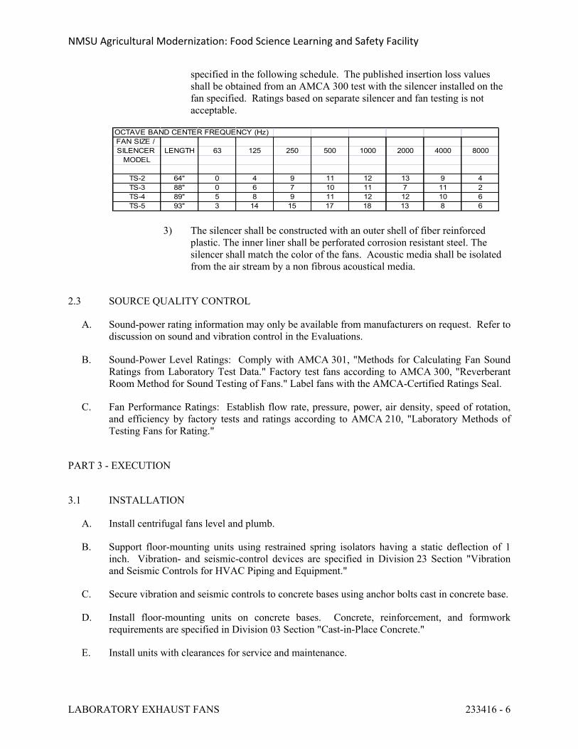
NMSU Agricultural Modernization: Food Science Learning and Safety Facility
LABORATORY EXHAUST FANS 233416 - 6
specified in the following schedule. The published insertion loss values shall be obtained from an AMCA 300 test with the silencer installed on the fan specified. Ratings based on separate silencer and fan testing is not acceptable.
OCTAVE BAND CENTER FREQUENCY (Hz)FAN SIZE / SILENCER LENGTH 63 125 250 500 1000 2000 4000 8000
MODEL
TS-2 64" 0 4 9 11 12 13 9 4TS-3 88" 0 6 7 10 11 7 11 2TS-4 89" 5 8 9 11 12 12 10 6TS-5 93" 3 14 15 17 18 13 8 6
3) The silencer shall be constructed with an outer shell of fiber reinforced plastic. The inner liner shall be perforated corrosion resistant steel. The silencer shall match the color of the fans. Acoustic media shall be isolated from the air stream by a non fibrous acoustical media.
2.3 SOURCE QUALITY CONTROL
A. Sound-power rating information may only be available from manufacturers on request. Refer to discussion on sound and vibration control in the Evaluations.
B. Sound-Power Level Ratings: Comply with AMCA 301, "Methods for Calculating Fan Sound Ratings from Laboratory Test Data." Factory test fans according to AMCA 300, "Reverberant Room Method for Sound Testing of Fans." Label fans with the AMCA-Certified Ratings Seal.
C. Fan Performance Ratings: Establish flow rate, pressure, power, air density, speed of rotation, and efficiency by factory tests and ratings according to AMCA 210, "Laboratory Methods of Testing Fans for Rating."
PART 3 - EXECUTION
3.1 INSTALLATION
A. Install centrifugal fans level and plumb.
B. Support floor-mounting units using restrained spring isolators having a static deflection of 1 inch. Vibration- and seismic-control devices are specified in Division 23 Section "Vibration and Seismic Controls for HVAC Piping and Equipment."
C. Secure vibration and seismic controls to concrete bases using anchor bolts cast in concrete base.
D. Install floor-mounting units on concrete bases. Concrete, reinforcement, and formwork requirements are specified in Division 03 Section "Cast-in-Place Concrete."
E. Install units with clearances for service and maintenance.
NMSU Agricultural Modernization: Food Science Learning and Safety Facility
LABORATORY EXHAUST FANS 233416 - 7
F. Label fans according to requirements specified in Division 23 Section "Identification for HVAC Piping and Equipment."
3.2 CONNECTIONS
A. Coordinate duct installations and specialty arrangements with schematics on Drawings and with requirements specified in duct systems. If Drawings are explicit enough, these requirements may be reduced or omitted.
B. Duct installation and connection requirements are specified in other Division 23 Sections. Drawings indicate general arrangement of ducts and duct accessories. Make final duct connections with flexible connectors. Flexible connectors are specified in Division 23 Section "Air Duct Accessories."
C. Install ducts adjacent to fans to allow service and maintenance.
D. Install line-sized piping from scroll drain connection, with trap with seal equal to 1.5 times specified static pressure, to nearest floor drain.
E. Ground equipment according to Division 26 Section "Grounding and Bonding for Electrical Systems."
F. Connect wiring according to Division 26 Section "Low-Voltage Electrical Power Conductors and Cables."
3.3 FIELD QUALITY CONTROL
A. Perform the following field tests and inspections and prepare test reports:
1. Verify that shipping, blocking, and bracing are removed.2. Verify that unit is secure on mountings and supporting devices and that connections to
ducts and electrical components are complete. Verify that proper thermal-overload protection is installed in motors, starters, and disconnect switches.
3. Verify that cleaning and adjusting are complete.4. Disconnect fan drive from motor, verify proper motor rotation direction, and verify fan
wheel free rotation and smooth bearing operation. Reconnect fan drive system, align and adjust belts, and install belt guards.
5. Adjust belt tension.6. Adjust damper linkages for proper damper operation.7. Verify lubrication for bearings and other moving parts.8. Verify that manual and automatic volume control and fire and smoke dampers in
connected ductwork systems are in fully open position.9. Refer to Division 23 Section "Testing, Adjusting, and Balancing for HVAC" for testing,
adjusting, and balancing procedures.10. Remove and replace malfunctioning units and retest as specified above.
B. Test and adjust controls and safeties. Replace damaged and malfunctioning controls and equipment.
NMSU Agricultural Modernization: Food Science Learning and Safety Facility
LABORATORY EXHAUST FANS 233416 - 8
END OF SECTION 233416
NMSU Agricultural Modernization: Food Science Learning and Safety Facility
HVAC POWER VENTILATORS 233423 - 1
SECTION 233423 - HVAC POWER VENTILATORS
PART 1 - GENERAL
1.1 SUMMARY
A. This Section includes the following:
1. Centrifugal roof ventilators.2. Centrifugal wall ventilators.3. Ceiling-mounting ventilators.4. In-line centrifugal fans.
1.2 SUBMITTALS
A. Product Data: Include rated capacities, furnished specialties, and accessories for each type of product indicated and include the following:
B. Shop Drawings: Detail equipment assemblies and indicate dimensions, weights, loads, required clearances, method of field assembly, components, and location and size of each field connection.
C. Field quality-control test reports.
D. Operation and maintenance data.
1.3 QUALITY ASSURANCE
A. Electrical Components, Devices, and Accessories: Listed and labeled as defined in NFPA 70, Article 100, by a testing agency acceptable to authorities having jurisdiction, and marked for intended use.
B. NEMA Compliance: Motors and electrical accessories shall comply with NEMA standards.
C. UL Standard: Power ventilators shall comply with UL 705.
PART 2 - PRODUCTS
2.1 CENTRIFUGAL ROOF VENTILATORS
A. Available Manufacturers: Subject to compliance with requirements, manufacturers offering products that may be incorporated into the Work include, but are not limited to, the following:
B. Manufacturers: Subject to compliance with requirements, provide products by one of the following:
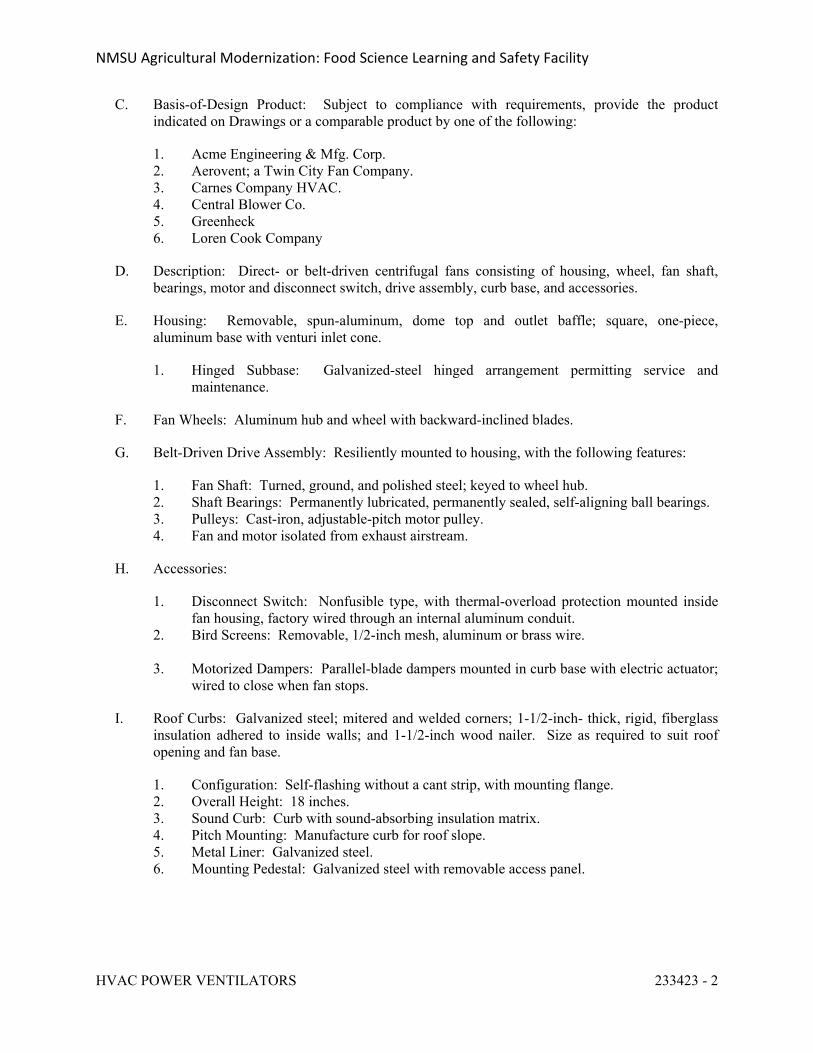
NMSU Agricultural Modernization: Food Science Learning and Safety Facility
HVAC POWER VENTILATORS 233423 - 2
C. Basis-of-Design Product: Subject to compliance with requirements, provide the product indicated on Drawings or a comparable product by one of the following:
1. Acme Engineering & Mfg. Corp.2. Aerovent; a Twin City Fan Company.3. Carnes Company HVAC.4. Central Blower Co.5. Greenheck6. Loren Cook Company
D. Description: Direct- or belt-driven centrifugal fans consisting of housing, wheel, fan shaft, bearings, motor and disconnect switch, drive assembly, curb base, and accessories.
E. Housing: Removable, spun-aluminum, dome top and outlet baffle; square, one-piece, aluminum base with venturi inlet cone.
1. Hinged Subbase: Galvanized-steel hinged arrangement permitting service and maintenance.
F. Fan Wheels: Aluminum hub and wheel with backward-inclined blades.
G. Belt-Driven Drive Assembly: Resiliently mounted to housing, with the following features:
1. Fan Shaft: Turned, ground, and polished steel; keyed to wheel hub.2. Shaft Bearings: Permanently lubricated, permanently sealed, self-aligning ball bearings.3. Pulleys: Cast-iron, adjustable-pitch motor pulley.4. Fan and motor isolated from exhaust airstream.
H. Accessories:
1. Disconnect Switch: Nonfusible type, with thermal-overload protection mounted inside fan housing, factory wired through an internal aluminum conduit.
2. Bird Screens: Removable, 1/2-inch mesh, aluminum or brass wire.
3. Motorized Dampers: Parallel-blade dampers mounted in curb base with electric actuator; wired to close when fan stops.
I. Roof Curbs: Galvanized steel; mitered and welded corners; 1-1/2-inch- thick, rigid, fiberglass insulation adhered to inside walls; and 1-1/2-inch wood nailer. Size as required to suit roof opening and fan base.
1. Configuration: Self-flashing without a cant strip, with mounting flange.2. Overall Height: 18 inches.3. Sound Curb: Curb with sound-absorbing insulation matrix.4. Pitch Mounting: Manufacture curb for roof slope.5. Metal Liner: Galvanized steel.6. Mounting Pedestal: Galvanized steel with removable access panel.
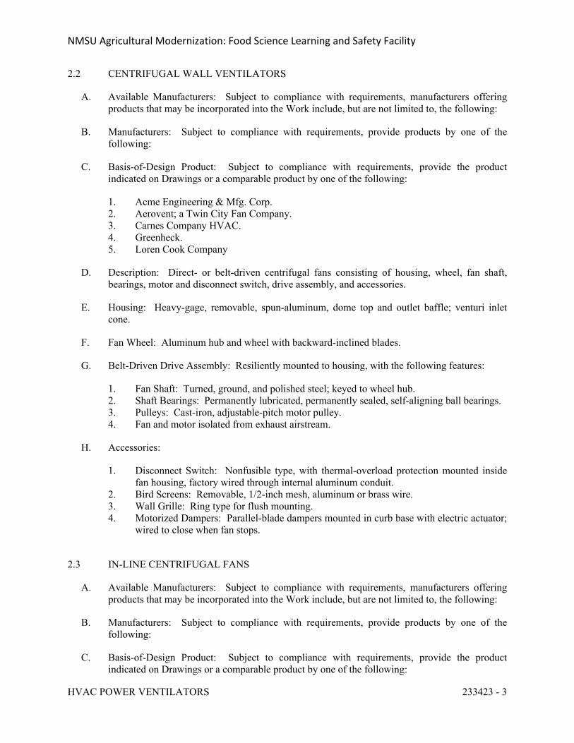
NMSU Agricultural Modernization: Food Science Learning and Safety Facility
HVAC POWER VENTILATORS 233423 - 3
2.2 CENTRIFUGAL WALL VENTILATORS
A. Available Manufacturers: Subject to compliance with requirements, manufacturers offering products that may be incorporated into the Work include, but are not limited to, the following:
B. Manufacturers: Subject to compliance with requirements, provide products by one of the following:
C. Basis-of-Design Product: Subject to compliance with requirements, provide the product indicated on Drawings or a comparable product by one of the following:
1. Acme Engineering & Mfg. Corp.2. Aerovent; a Twin City Fan Company.3. Carnes Company HVAC.4. Greenheck.5. Loren Cook Company
D. Description: Direct- or belt-driven centrifugal fans consisting of housing, wheel, fan shaft, bearings, motor and disconnect switch, drive assembly, and accessories.
E. Housing: Heavy-gage, removable, spun-aluminum, dome top and outlet baffle; venturi inlet cone.
F. Fan Wheel: Aluminum hub and wheel with backward-inclined blades.
G. Belt-Driven Drive Assembly: Resiliently mounted to housing, with the following features:
1. Fan Shaft: Turned, ground, and polished steel; keyed to wheel hub.2. Shaft Bearings: Permanently lubricated, permanently sealed, self-aligning ball bearings.3. Pulleys: Cast-iron, adjustable-pitch motor pulley.4. Fan and motor isolated from exhaust airstream.
H. Accessories:
1. Disconnect Switch: Nonfusible type, with thermal-overload protection mounted inside fan housing, factory wired through internal aluminum conduit.
2. Bird Screens: Removable, 1/2-inch mesh, aluminum or brass wire.3. Wall Grille: Ring type for flush mounting.4. Motorized Dampers: Parallel-blade dampers mounted in curb base with electric actuator;
wired to close when fan stops.
2.3 IN-LINE CENTRIFUGAL FANS
A. Available Manufacturers: Subject to compliance with requirements, manufacturers offering products that may be incorporated into the Work include, but are not limited to, the following:
B. Manufacturers: Subject to compliance with requirements, provide products by one of the following:
C. Basis-of-Design Product: Subject to compliance with requirements, provide the product indicated on Drawings or a comparable product by one of the following:
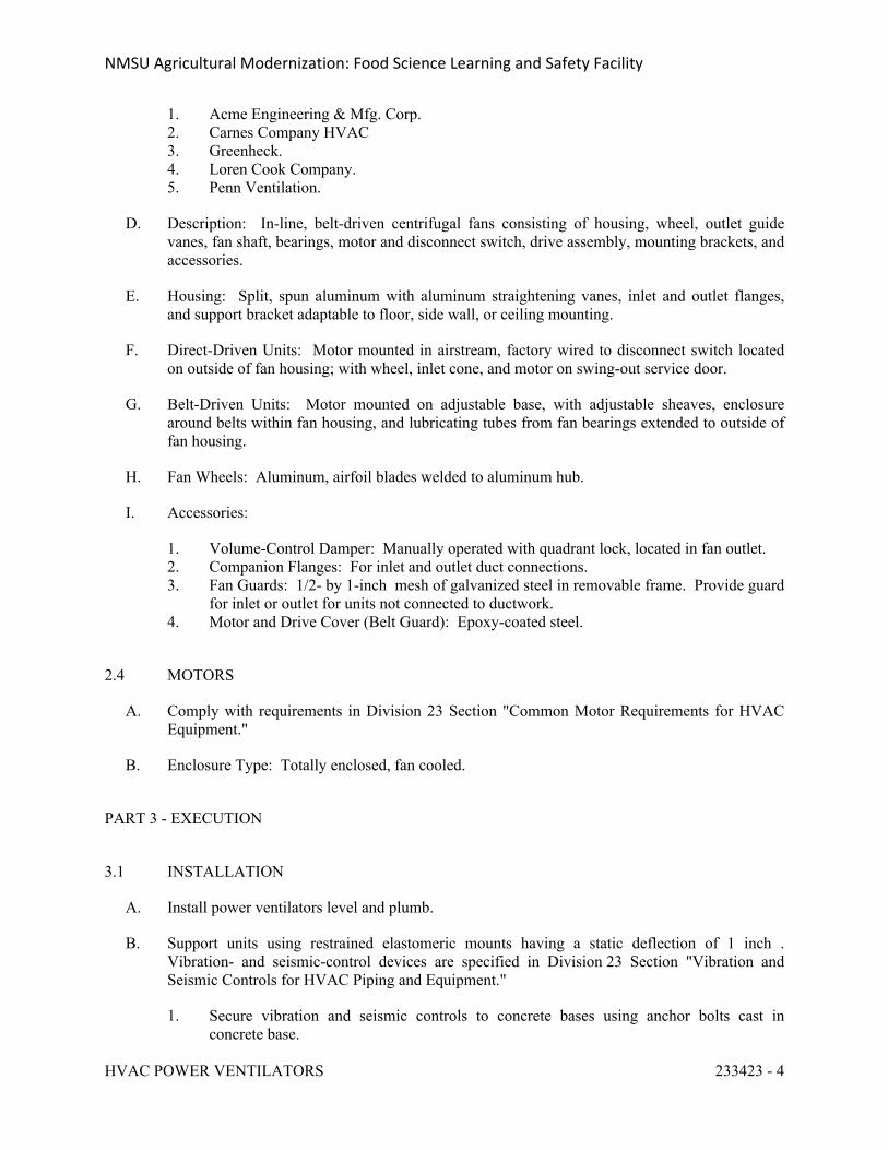
NMSU Agricultural Modernization: Food Science Learning and Safety Facility
HVAC POWER VENTILATORS 233423 - 4
1. Acme Engineering & Mfg. Corp.2. Carnes Company HVAC3. Greenheck.4. Loren Cook Company.5. Penn Ventilation.
D. Description: In-line, belt-driven centrifugal fans consisting of housing, wheel, outlet guide vanes, fan shaft, bearings, motor and disconnect switch, drive assembly, mounting brackets, and accessories.
E. Housing: Split, spun aluminum with aluminum straightening vanes, inlet and outlet flanges, and support bracket adaptable to floor, side wall, or ceiling mounting.
F. Direct-Driven Units: Motor mounted in airstream, factory wired to disconnect switch located on outside of fan housing; with wheel, inlet cone, and motor on swing-out service door.
G. Belt-Driven Units: Motor mounted on adjustable base, with adjustable sheaves, enclosure around belts within fan housing, and lubricating tubes from fan bearings extended to outside of fan housing.
H. Fan Wheels: Aluminum, airfoil blades welded to aluminum hub.
I. Accessories:
1. Volume-Control Damper: Manually operated with quadrant lock, located in fan outlet.2. Companion Flanges: For inlet and outlet duct connections.3. Fan Guards: 1/2- by 1-inch mesh of galvanized steel in removable frame. Provide guard
for inlet or outlet for units not connected to ductwork.4. Motor and Drive Cover (Belt Guard): Epoxy-coated steel.
2.4 MOTORS
A. Comply with requirements in Division 23 Section "Common Motor Requirements for HVAC Equipment."
B. Enclosure Type: Totally enclosed, fan cooled.
PART 3 - EXECUTION
3.1 INSTALLATION
A. Install power ventilators level and plumb.
B. Support units using restrained elastomeric mounts having a static deflection of 1 inch . Vibration- and seismic-control devices are specified in Division 23 Section "Vibration and Seismic Controls for HVAC Piping and Equipment."
1. Secure vibration and seismic controls to concrete bases using anchor bolts cast in concrete base.
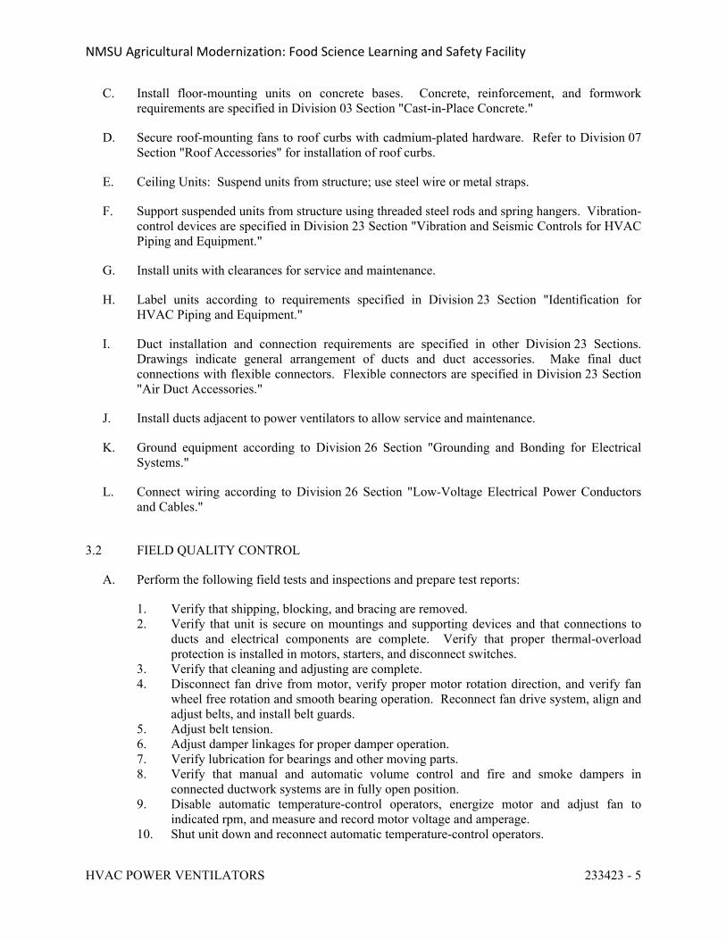
NMSU Agricultural Modernization: Food Science Learning and Safety Facility
HVAC POWER VENTILATORS 233423 - 5
C. Install floor-mounting units on concrete bases. Concrete, reinforcement, and formwork requirements are specified in Division 03 Section "Cast-in-Place Concrete."
D. Secure roof-mounting fans to roof curbs with cadmium-plated hardware. Refer to Division 07 Section "Roof Accessories" for installation of roof curbs.
E. Ceiling Units: Suspend units from structure; use steel wire or metal straps.
F. Support suspended units from structure using threaded steel rods and spring hangers. Vibration-control devices are specified in Division 23 Section "Vibration and Seismic Controls for HVAC Piping and Equipment."
G. Install units with clearances for service and maintenance.
H. Label units according to requirements specified in Division 23 Section "Identification for HVAC Piping and Equipment."
I. Duct installation and connection requirements are specified in other Division 23 Sections. Drawings indicate general arrangement of ducts and duct accessories. Make final duct connections with flexible connectors. Flexible connectors are specified in Division 23 Section "Air Duct Accessories."
J. Install ducts adjacent to power ventilators to allow service and maintenance.
K. Ground equipment according to Division 26 Section "Grounding and Bonding for Electrical Systems."
L. Connect wiring according to Division 26 Section "Low-Voltage Electrical Power Conductors and Cables."
3.2 FIELD QUALITY CONTROL
A. Perform the following field tests and inspections and prepare test reports:
1. Verify that shipping, blocking, and bracing are removed.2. Verify that unit is secure on mountings and supporting devices and that connections to
ducts and electrical components are complete. Verify that proper thermal-overload protection is installed in motors, starters, and disconnect switches.
3. Verify that cleaning and adjusting are complete.4. Disconnect fan drive from motor, verify proper motor rotation direction, and verify fan
wheel free rotation and smooth bearing operation. Reconnect fan drive system, align and adjust belts, and install belt guards.
5. Adjust belt tension.6. Adjust damper linkages for proper damper operation.7. Verify lubrication for bearings and other moving parts.8. Verify that manual and automatic volume control and fire and smoke dampers in
connected ductwork systems are in fully open position.9. Disable automatic temperature-control operators, energize motor and adjust fan to
indicated rpm, and measure and record motor voltage and amperage.10. Shut unit down and reconnect automatic temperature-control operators.
NMSU Agricultural Modernization: Food Science Learning and Safety Facility
HVAC POWER VENTILATORS 233423 - 6
11. Remove and replace malfunctioning units and retest as specified above.
B. Test and adjust controls and safeties. Replace damaged and malfunctioning controls and equipment.
END OF SECTION 23 3423
NMSU Agricultural Modernization: Food Science Learning and Safety Facility
DIFFUSER, REGISTERS, AND GRILLES 233713 - 1
SECTION 233713 - DIFFUSERS, REGISTERS, AND GRILLES
PART 1 - GENERAL
1.1 SUMMARY
A. Section Includes:
1. Round ceiling diffusers.2. Rectangular and square ceiling diffusers.3. Perforated diffusers.4. Louver face diffusers.5. Fixed face registers and grilles.6. Laboratory Diffusers7. Plastic Grilles
B. Related Sections:
1. Division 08 Section "Louvers and Vents" for fixed and adjustable louvers and wall vents, whether or not they are connected to ducts.
2. Division 23 Section "Air Duct Accessories" for fire and smoke dampers and volume-control dampers not integral to diffusers, registers, and grilles.
1.2 SUBMITTALS
A. Product Data: For each type of product indicated, include the following:
1. Data Sheet: Indicate materials of construction, finish, and mounting details; and performance data including throw and drop, static-pressure drop, and noise ratings.
2. Diffuser, Register, and Grille Schedule: Indicate drawing designation, room location, quantity, model number, size, and accessories furnished.
B. Samples: For each exposed product and for each color and texture specified.
PART 2 - PRODUCTS
2.1 CEILING DIFFUSERS
A. Round Ceiling Diffuser:
1. Manufacturers: Subject to compliance with requirements, available manufacturers offering products that may be incorporated into the Work include, but are not limited to, the following:
a. Anemostat Products; a Mestek company.b. Carnes.
NMSU Agricultural Modernization: Food Science Learning and Safety Facility
DIFFUSER, REGISTERS, AND GRILLES 233713 - 2
c. Hart & Cooley Inc.d. METALAIRE, Inc.e. Nailor Industries Inc.f. Price Industries.g. Titus.h. Tuttle & Bailey.
2. Devices shall be specifically designed for variable-air-volume flows.3. Material: Steel.4. Finish: Baked enamel, white.5. Face Style: Four cone.6. Mounting: Duct connection.7. Pattern: Fully adjustable.8. Dampers: Radial opposed blade.
B. Rectangular and Square Ceiling Diffusers:
1. Manufacturers: Subject to compliance with requirements, provide products by one of the following:
a. Anemostat Products; a Mestek company.b. Carnes.c. Hart & Cooley Inc.d. Krueger.e. METALAIRE, Inc.f. Nailor Industries Inc.g. Price Industries.h. Titus.i. Tuttle & Bailey..
2. Devices shall be specifically designed for variable-air-volume flows.3. Material: Steel.4. Finish: Baked enamel, white.
C. Perforated Diffuser:
1. Manufacturers: Subject to compliance with requirements, available manufacturers offering products that may be incorporated into the Work include, but are not limited to, the following:
a. Anemostat Products; a Mestek company.b. Carnes.c. Hart & Cooley Inc.d. Krueger.e. METALAIRE, Inc.f. Nailor Industries Inc.g. Price Industries.h. Titus.i. Tuttle & Bailey.
2. Devices shall be specifically designed for variable-air-volume flows.
NMSU Agricultural Modernization: Food Science Learning and Safety Facility
DIFFUSER, REGISTERS, AND GRILLES 233713 - 3
3. Material: Steel backpan and pattern controllers, with steel face.4. Finish: Baked enamel, white.5. Duct Inlet: Round.
D. Louver Face Diffuser:
1. Manufacturers: Subject to compliance with requirements, available manufacturers offering products that may be incorporated into the Work include, but are not limited to, the following:
2. Basis-of-Design Product: Subject to compliance with requirements, provide product indicated on Drawings or comparable product by one of the following:
a. Anemostat Products; a Mestek company.b. Carnes.c. METALAIRE, Inc.d. Nailor Industries Inc.e. Price Industries.f. Titus.g. Tuttle & Bailey.
3. Devices shall be specifically designed for variable-air-volume flows.4. Material: Steel.5. Finish: Baked enamel, white.
2.2 REGISTERS AND GRILLES
A. Adjustable Bar Register:
1. Manufacturers: Subject to compliance with requirements, available manufacturers offering products that may be incorporated into the Work include, but are not limited to, the following:
a. Anemostat Products; a Mestek company.b. Carnes.c. Hart & Cooley Inc.d. Krueger.e. METALAIRE, Inc.f. Nailor Industries Inc.g. Price Industries.h. Titus.i. Tuttle & Bailey.
2. Material: Steel.3. Finish: Baked enamel, white.
B. Fixed Face Register:
1. Manufacturers: Subject to compliance with requirements, available manufacturers offering products that may be incorporated into the Work include, but are not limited to, the following:
NMSU Agricultural Modernization: Food Science Learning and Safety Facility
DIFFUSER, REGISTERS, AND GRILLES 233713 - 4
a. Anemostat Products; a Mestek company.b. Carnes.c. Hart & Cooley Inc.d. Krueger.e. Nailor Industries Inc.f. Price Industries.g. Titus.h. Tuttle & Bailey.
2. Material: Steel.3. Finish: Baked enamel, white
C. Fixed Face Grille:
1. Manufacturers: Subject to compliance with requirements, available manufacturers offering products that may be incorporated into the Work include, but are not limited to, the following:
a. Anemostat Products; a Mestek company.b. Carnes.c. Hart & Cooley Inc.d. Krueger.e. Nailor Industries Inc.f. Price Industries.g. Titus.h. Tuttle & Bailey.
2. Material: Steel.3. Finish: Baked enamel, white.
2.3 LABORATORY DIFFUSERS
A. Laminar Airflow Diffusers:
1. Manufacturers: Subject to compliance with requirements, available manufacturers offering products that may be incorporated into the Work include, but are not limited to, the following:
a. Anemostat Products; a Mestek company.b. Carnes.c. Hart & Cooley Inc.d. Krueger.e. METALAIRE, Inc.f. Nailor Industries Inc.g. Price Industries.h. Titus.i. Tuttle & Bailey.

NMSU Agricultural Modernization: Food Science Learning and Safety Facility
DIFFUSER, REGISTERS, AND GRILLES 233713 - 5
General Construction : Units shall be manufactured specifically for Laboratory usage. Aluminum construction, with a perforated face that extends below the ceiling plane. The units dhall be non-aspirating and deliver air in a radial pattern.
2. Finish: Baked enamel, white.3. Provide a minium 6” backpan for even air flow distribution over the entire face of the
diffuser.
B. Plastic Diffusers:
1. Manufacturers: Subject to compliance with requirements, available manufacturers offering products that may be incorporated into the Work include, but are not limited to, the following:
a. Anemostat Products; a Mestek company.b. Carnes.c. Hart & Cooley Inc.d. Krueger.e. Nailor Industries Inc.f. Price Industries.g. Titus.h. Tuttle & Bailey.
2. See drawings for Plastic diffuser locations3. Material: Plastic4. Finish: Baked enamel, white
2.4 SOURCE QUALITY CONTROL
A. Verification of Performance: Rate diffusers, registers, and grilles according to ASHRAE 70, "Method of Testing for Rating the Performance of Air Outlets and Inlets."
PART 3 - EXECUTION
3.1 INSTALLATION
A. Install diffusers, registers, and grilles level and plumb.
B. Ceiling-Mounted Outlets and Inlets: Drawings indicate general arrangement of ducts, fittings, and accessories. Air outlet and inlet locations have been indicated to achieve design requirements for air volume, noise criteria, airflow pattern, throw, and pressure drop. Make final locations where indicated, as much as practical. For units installed in lay-in ceiling panels, locate units in the center of panel. Where architectural features or other items conflict with installation, notify Architect for a determination of final location.
C. Install diffusers, registers, and grilles with airtight connections to ducts and to allow service and maintenance of dampers, air extractors, and fire dampers.
NMSU Agricultural Modernization: Food Science Learning and Safety Facility
DIFFUSER, REGISTERS, AND GRILLES 233713 - 6
3.2 ADJUSTING
A. After installation, adjust diffusers, registers, and grilles to air patterns indicated, or as directed, before starting air balancing.
END OF SECTION 233713
NMSU Agricultural Modernization: Food Science Learning and Safety Facility
SCROLL AIR COOLED CHILLERS 236423 - 1
SECTION 236423 - SCROLL AIR COOLED CHILLERS
PART 1 - GENERAL
1.1 RELATED DOCUMENTS
A. Drawings and general provisions of the Contract, including General and Supplementary Conditions and Division 01 Specification Sections, apply to this Section.
1.2 SUMMARY
A. Section Includes:
1. Packaged, air-cooled, electric-motor-driven, scroll air cooled chillers.
B. Related Sections:
1. Section 283500 "Refrigerant Detection and Alarm" for refrigerant monitors, alarms, supplemental breathing apparatus, and ventilation equipment interlocks.
1.3 DEFINITIONS
A. COP: Coefficient of performance. The ratio of the rate of heat removal to the rate of energy input using consistent units for any given set of rating conditions.
B. EER: Energy-efficiency ratio. The ratio of the cooling capacity given in terms of Btu/h to the total power input given in terms of watts at any given set of rating conditions.
C. IPLV: Integrated part-load value. A single number part-load efficiency figure of merit calculated per the method defined by ARI 506/110 and referenced to ARI standard rating conditions.
D. kW/Ton: The ratio of total power input of the chiller in kilowatts to the net refrigerating capacity in tons at any given set of rating conditions.
E. NPLV: Nonstandard part-load value. A single number part-load efficiency figure of merit calculated per the method defined by ARI 506/110 and intended for operating conditions other than the ARI standard rating conditions.
1.4 PERFORMANCE REQUIREMENTS
A. Seismic Performance: Scroll water chillers shall withstand the effects of earthquake motions indicated in 23 0548 Vib & Seismic Controls.
NMSU Agricultural Modernization: Food Science Learning and Safety Facility
SCROLL AIR COOLED CHILLERS 236423 - 2
1. The term "withstand" means "the unit will remain in place without separation of any parts from the device when subjected to the seismic forces specified.
1.5 QUALITY ASSURANCE
A. Qualifications: Equipment manufacturer must specialize in the manufacture of the products specified and have five years experience with the type of equipment.
B. Regulatory Requirements: Comply with the codes and standards specified.
C. Chiller manufacturer plant must be ISO Registered.
D. Products shall be Designed, Tested, Rated and Certified in accordance with, and Installed in compliance with applicable sections of the following Standards and Codes:
1. AHRI 550/590 – Water Chilling Packages Using the Vapor Compression Cycle2. AHRI 370 – Sound Rating of Large Outdoor Refrigerating and Air-Conditioning
Equipment3. ANSI/ASHRAE 15 – Safety Code for Mechanical Refrigeration4. ASHRAE 90.1 – Energy Standard for Buildings Except Low-Rise Residential Buildings5. ANSI/NFPA 70 – National Electrical Code (N.E.C.)6. ASME Boiler and Pressure Vessel Code, Section VIII, Division 17. OSHA – Occupational Safety and Health Act8. Manufactured in facility registered to ISO 90019. Conform to Intertek Testing Services for construction of chillers and provide ETL/cETL
Listed Mark
E. Factory Run Test: Chiller shall be pressure-tested, evacuated and fully charged with refrigerant and oil, and shall be factory operational run tested with water flowing through the vessel.
F. Chiller manufacturer shall have a factory trained and supported service organization.
1.6 DELIVERY AND HANDLING
A. Comply with the manufacturer's instructions for rigging and handling equipment.
B. Unit shall be delivered to job site fully assembled with all interconnecting refrigerant piping and internal wiring ready for field installation and charged with refrigerant and oil by the Manufacturer.
C. Unit shall be stored and handled per Manufacturer’s instructions.
D. Protect the chiller and its accessories from the weather and dirt exposure during shipment.
E. During shipment, provide protective covering over vulnerable components. Fit nozzles and open ends with plastic enclosures.
NMSU Agricultural Modernization: Food Science Learning and Safety Facility
SCROLL AIR COOLED CHILLERS 236423 - 3
1.7 WARRANTY
A. Standard Warranty (Domestic): The refrigeration equipment manufacturer's warranty shall be for a period of one (1) year from date of equipment start up, but not more than 18 months from shipment. It shall cover replacement parts having proven defective within the above period.
B. 1st Year Labor Warranty:Included
C. Extended Compressor Warranty: Four (5) years extended compressor warranty, parts only.
1.8 MAINTENANCE
A. Maintenance of the chillers shall be the responsibility of the owner and performed in accordance with the manufacturer’s instructions.
PART 2 - PRODUCTS
2.1 ACCEPTABLE MANUFACTURERS
A. Manufacturers: Subject to compliance with requirements, provide products by one of the following:
1. York or prior approved equal.
2.2 UNIT DESCRIPTION
A. General: Install and commission, as shown on the schedules and plans, factory assembled, charged, and tested air cooled scroll compressor chiller(s) as specified herein. Chiller shall be designed, selected, and constructed using a refrigerant with Flammability rating of “1”, as defined by ANSI/ASHRAE STANDARD - 34 Number Designation and Safety Classification of Refrigerants. Chiller shall include, but is not limited to: a complete system with a single refrigerant circuit 35 tons (123kW) and below, and not less than two refrigerant circuits above 35 tons (123kW), scroll compressors, direct expansion type evaporator, air-cooled condenser, refrigerant, lubrication system, interconnecting wiring, safety and operating controls including capacity controller, control center, motor starting components, and special features as specified herein or required for safe, automatic operation.
B. Cabinet: External structural members shall be constructed of heavy guage, galvanized steel coated with baked on powder paint which, when subject to ASTM B117, 1000 hour, 5% salt spray test, yields minimum ASTM 1654 rating of "6".
C. Louvered Panels (full unit): Painted steel as per remainder of unit cabinet, to protect condenser coils from incidental damage, visually screen internal components, and prevent unauthorized access to internal components. Factory installed.
NMSU Agricultural Modernization: Food Science Learning and Safety Facility
SCROLL AIR COOLED CHILLERS 236423 - 4
2.3 DESIGN REQUIREMENTS
A. General: Provide a complete scroll compressor packaged chiller as specified herein and as shown on the drawings. The unit shall be in accordance with the standards referenced in section 1.02 and any local codes in effect.
B. Performance: Refer to the schedule of performance on the drawings.
2.4 CHILLER COMPONENTS
A. Compressor
1. The Compressors: Shall be hermetic, scroll-type, including:2. Compliant design for axial and radial sealing.3. Refrigerant flow through the compressor with 100% suction cooled motor.4. Large suction side free volume and oil sump to provide liquid handling capability.5. Compressor crankcase heaters to provide extra liquid migration protection.6. Annular discharge check valve and reverse vent assembly to provide low-pressure drop,
silent shutdown and reverse rotation protection.7. Initial oil charge.8. Oil level sight glass.9. Vibration isolator mounts for compressors.10. Brazed-type connections for fully hermetic refrigerant circuits.
B. REFRIGERANT CIRCUIT COMPONENTS
1. Each refrigerant circuit shall include: liquid line shutoff valve with charging port, low side pressure relief device, filter-drier, solenoid valve, sight glass with moisture indicator, thermostatic expansion valves, and flexible, closed-cell foam insulated suction line and suction pressure transducer.
C. HEAT EXCHANGERS
1. Evaporator:2. Evaporator shall be brazed-plate stainless steel construction, single or dual circuit heat
exchangers capable of refrigerant working pressure of 650 PSIG (4482 kPa) and liquid side pressure of 150 psig (1034 kPa)
3. Brazed plate heat exchangers shall be UL listed.4. Exterior surfaces shall be covered with 3.4" (19mm), flexible, closed cell insulation,
thermal conductivity of 0.26k ([BTU/HR-Ft² - °F]/in.) maximum.5. Cooler shall have a factory installed thermostatically controlled heater to protect to -20°F
(-29°C) ambient in off-cycle.6. Installing contractor must include accommodations in the chilled water piping to allow
proper drainage and venting of the heat exchanger. A strainer with a mesh size between .5 and 1.5 mm is recommended upstream of the heat exchanger to prevent clogging.
7. Air-cooled Condenser:
NMSU Agricultural Modernization: Food Science Learning and Safety Facility
SCROLL AIR COOLED CHILLERS 236423 - 5
8. Coils: Internally enhanced, seamless copper tubes, mechanically expanded into aluminum alloy fins with full height collars. Sub-cooling coil an integral part of condenser. Design working pressure shall be 450 PSIG (31 bar).
9. Fans shall be dynamically and statically balanced, direct drive, corrosion resistant glass fiber reinforced composite blades molded into a low noise, full-airfoil cross section, providing vertical air discharge and low sound. Each fan in its own compartment to prevent crossflow during fan cycling. Guards of heavy gauge, PVC (polyvinylchloride) coated steel.
10. Fan Motors: High efficiency, direct drive, 6 pole, 3 phase, insulation class “F”, current protected, Totally Enclosed Air-Over (TEAO) , rigid mounted, with double sealed, permanently lubricated, ball bearings.
D. CONTROLS
1. General: Automatic start, stop, operating, and protection sequences across the range of scheduled conditions and transients.
2. Microprocessor Enclosure: Rain and dust tight NEMA 3R/12 (IP55) powder painted steel cabinet and gasket sealed door.
3. Microprocessor Control Center:4. Automatic control of compressor start/stop, anti-coincidence and anti-recycle timers,
automatic pumpdown at system shutdown, condenser fans, evaporator pump, evaporator heater, unit alarm contacts, and chiller operation from 0°F to 125°F (-18°C to 52°C) ambient. Automatic reset to normal chiller operation after power failure.
5. Software stored in non-volatile memory, with programmed setpoints retained in lithium battery backed real-time-clock (RTC) memory for minimum 5 years.
6. Forty character liquid crystal display, descriptions in English (or Spanish, French, Italian, or German), numeric data in English (or Metric) units. Sealed keypad with sections for Setpoints, Display/Print, Entry, Unit Options & clock, and On/Off Switch.
7. Programmable Setpoints (within Manufacturer limits): display language; chilled liquid temperature setpoint and range, remote reset temperature range, daily schedule/holiday for start/stop, manual override for servicing, low and high ambient cutouts, low liquid temperature cutout, low suction pressure cutout, high discharge pressure cutout, anti-recycle timer (compressor start cycle time), and anti-coincident timer (delay compressor starts).
8. Display Data: Return and leaving liquid temperatures, low leaving liquid temperature cutout setting, low ambient temperature cutout setting, outdoor air temperature, English or metric data, suction pressure cutout setting, each system suction pressure (optional on YCAL0014-0060 models), discharge pressure (optional), liquid temperature reset via a YORK ISN DDC or Building Automation System (by others) via a 4-20milliamp or 0-10 VDC input with optional BAS interface, anti-recycle timer status for each compressor, anti-coincident system start timer condition, compressor run status, no cooling load condition, day, date and time, daily start/stop times, holiday status, automatic or manual system lead/lag control, lead system definition, compressor starts/operating hours (each), status of hot gas valves, evaporator heater and fan operation, run permissive status, number of compressors running, liquid solenoid valve status, load & unload timer status, water pump status.
9. System Safeties: Shall cause individual compressor systems to perform auto shut down; manual reset required after the third trip in 90 minutes. System Safeties include: high discharge pressure, low suction pressure, high pressure switch, and motor protector.
NMSU Agricultural Modernization: Food Science Learning and Safety Facility
SCROLL AIR COOLED CHILLERS 236423 - 6
Compressor motor protector shall protect against damage due to high input current or thermal overload of windings.
10. Unit Safeties: Shall be automatic reset and cause compressors to shut down if low ambient, low leaving chilled liquid temperature, under voltage, and flow switch operation. Contractor shall provide flow switch and wiring per chiller manufacturer requirements.
11. Alarm Contacts: Low ambient, low leaving chilled liquid temperature, low voltage, low battery, and (per compressor circuit): high discharge pressure, and low suction pressure.
12. Manufacturer shall provide any controls not listed above, necessary for automatic chiller operation. Mechanical Contractor shall provide field control wiring necessary to interface sensors to the chiller control system.
E. POWER CONNECTION AND DISTRIBUTION
1. NEMA 3R/12 (IP55) rain/dust tight, powder painted steel cabinets with gasket sealed outer doors. Provide main power connection(s), control power connections, compressor and fan motor start contactors, current overloads, and factory wiring.
2. Power supply shall enter unit at a single location, be 3 phase of scheduled voltage, and connect to individual terminal blocks per compressor.
3. Exposed compressor, control and fan motor power wiring shall be routed through liquid tight conduit.
F. ACCESSORIES AND OPTIONS
1. Microprocessor controlled, Factory installed Across-the-Line type compressor motor starters as standard.
2. Low Ambient Control: Permits unit operation to 0°F ambient.3. High Ambient Control (Factory Mounted): Permits unit operation above 115°F ambient.4. Single Point Disconnect: Single point Non-Fused Disconnect(s) and lockable external
handle (in compliance with Article 440-14 of N.E.C.) shall be supplied to isolate the unit power voltage for servicing. Separate external fusing must be supplied, by others, in the incoming power wiring, which must comply with the National Electric Code and/or local codes.
5. Control Power Transformer: Converts unit power voltage to 120-1-60 (500 VA capacity). Factory-mounting includes primary and secondary wiring between the transformer and the control panel.
6. Pressure Transducers and Readout Capability:7. Discharge Pressure Transducers: Permits unit to sense and display discharge pressure.8. Protective Chiller Panels (Factory or Field Mounted)9. Louvered Panels (full unit): Painted steel of unit cabinet, to protect condenser coils from
incidental damage, visually screen internal components, and prevent unauthorized access to internal components.
10. Flow Switch (Field-mounted): Vapor proof SPDT, NEMA 3R switch, 150 PSIG (10.3 bar), -20°F to 250°F (-28.9°C to 121.1°C).
11. Hot Gas By-Pass: Permits continuous, stable operation at capacities below the minimum step of unloading to as low as 5% capacity (depending on both the unit & operating conditions) by introducing an artificial load on the evaporator. Hot gas by-pass is installed on only one refrigerant circuit.
12. Compressor Sound Blankets (Factory-mounted).
NMSU Agricultural Modernization: Food Science Learning and Safety Facility
SCROLL AIR COOLED CHILLERS 236423 - 7
13. Ultra Quiet fans, Low speed, reduced noise (Factory-mounted).14. Vibration Isolation (Field installed):15. Building Automation System (EMS) Reset Interface: Chiller to accept 4 to 20mA, 0 to 10
VDC, input to reset the leaving chilled liquid temperature.16. The chilled liquid lines that are exposed to outdoor ambient shall be wrapped with a
supplemental heater cable and covered with insulation.
G. Optional Factory-Installed Pump Package: None
PART 3 - EXECUTION
3.1 INSTALLATION
A. Install in strict accordance with manufacturer’s requirements, shop drawings, and contract documents.
B. Adjust and level chiller in alignment on supports.
C. Coordinate electrical installation with electrical contractor.
D. Coordinate controls with control contractor.
E. Install a field-supplied strainer in the chilled water return line at the evaporator inlet; 40-mesh on units with brazed-plate evaporators or 20-mesh on shell-and-tube evaporators.
3.2 CONNECTIONS
A. Coordinate piping installations and specialty arrangements with schematics on Drawings and with requirements specified in piping systems. If Drawings are explicit enough, these requirements may be omitted.
B. Comply with requirements in Section 232113 "Hydronic Piping" and Section 232116 Hydronic Piping Specialties." Drawings indicate general arrangement of piping, fittings, and specialties.
C. Comply with requirements in Section 232300 "Refrigerant Piping." Drawings indicate general arrangement of piping, fittings, and specialties.
D. Install piping adjacent to chiller to allow service and maintenance.
E. Evaporator Fluid Connections: Connect to evaporator inlet with shutoff valve, flexible connector, thermometer, and plugged tee with pressure gage. Connect to evaporator outlet with shutoff valve, balancing valve, flexible connector, flow switch, thermometer, plugged tee with pressure gage, and drain connection with valve. Make connections to water chiller with a flange.
F. Refrigerant Pressure Relief Valve Connections: For water chillers installed indoors, extend vent piping to the outside without valves or restrictions. Comply with ASHRAE 15.
NMSU Agricultural Modernization: Food Science Learning and Safety Facility
SCROLL AIR COOLED CHILLERS 236423 - 8
G. Connect each drain connection with a union and drain pipe and extend pipe, full size of connection, to floor drain. Provide a shutoff valve at each connection if required.
3.3 STARTUP SERVICE
A. A factory-authorized service representative to perform startup service.
B. Inspect field-assembled components, equipment installation, and piping and electrical connections for proper assemblies, installations, and connections.
C. Complete installation and startup checks according to manufacturer's written instructions and perform the following:
1. Verify that refrigerant charge is sufficient and water chiller has been leak tested.2. Verify that pumps are installed and functional.3. Verify that thermometers and gages are installed.4. Operate water chiller for run-in period.5. Check bearing lubrication and oil levels.6. Verify that refrigerant pressure relief device for chillers installed indoors is vented
outside.7. Verify proper motor rotation.8. Verify static deflection of vibration isolators, including deflection during water chiller
startup and shutdown.9. Verify and record performance of chilled-water flow and low-temperature interlocks.10. Verify and record performance of water chiller protection devices.11. Test and adjust controls and safeties. Replace damaged or malfunctioning controls and
equipment.
D. Prepare a written startup report that records results of tests and inspections.
3.4 DEMONSTRATION
A. A factory-authorized service representative shall train Owner's maintenance personnel to adjust, operate, and maintain water chillers. Video record the training sessions.
END OF SECTION 236423
NMSU Agricultural Modernization: Food Science Learning and Safety Facility
MODULAR INDOOR CENTRAL-STATION AIR-HANDLING UNITS & FIELDBUILT UP SYSTEMS & FAN ARRAYS 237313 - 1
SECTION 237313 - MODULAR INDOOR CENTRAL-STATION AIR-HANDLING UNITS & FIELD BUILT UP SYSTEMS & FAN ARRAYS
PART 1 - GENERAL
1.1 RELATED DOCUMENTS
A. Drawings and general provisions of the Contract, including General and Supplementary Conditions and Division 01 Specification Sections, apply to this Section.
1.2 RELATED SECTIONS
A. Section 23 05 00, Common Work Requirements for HVAC.
B. Section 23 05 04, Pipe and Pipe Fittings.
C. Section 23 05 05, Piping Specialties.
D. Section 23 05 23, Valves.
E. Section 23 07 00, HVAC Insulation.
F. Section 23 09 00, Facility Management System, for temperature control valves, meters and instrumentation.
G. Division 26, Electrical.
1.3 SUMMARY
A. Section Includes:
1. Modular Indoor Central Station Variable-Air-Volume Air-Handling Units.
1.4 PERFORMANCE REQUIREMENTS
A. Delegated Design: Design vibration isolation and seismic-restraint details, including comprehensive engineering analysis by a qualified professional engineer, using performance requirements and design criteria indicated.
B. Structural Performance: Casing panels shall be self-supporting and capable of withstanding 133 percent of internal static pressures indicated, without panel joints exceeding a deflection of L/100 where "L" is the unsupported span length within completed casings.
C. Seismic Performance: Air-handling units shall withstand the effects of earthquake motions determined according to ASCE/SEI.
NMSU Agricultural Modernization: Food Science Learning and Safety Facility
MODULAR INDOOR CENTRAL-STATION AIR-HANDLING UNITS & FIELDBUILT UP SYSTEMS & FAN ARRAYS 237313 - 2
1. The term "withstand" means "the unit will remain in place without separation of any parts from the device when subjected to the seismic forces specified and the unit will be fully operational after the seismic event."
1.5 ACTION SUBMITTALS
A. Product Data: For each air-handling unit indicated.
1. Unit dimensions and weight.2. Cabinet material, metal thickness, finishes, insulation, and accessories.3. Fans:
a. Certified fan-performance curves with system operating conditions indicated.b. Certified fan-sound power ratings.c. Fan construction and accessories.d. Motor ratings, electrical characteristics, and motor accessories.
4. Certified coil-performance ratings with system operating conditions indicated.5. Dampers, including housings, linkages, and operators.6. Filters with performance characteristics.
B. LEED Submittals:
1. Product Data for Prerequisite IEQ 1: Documentation indicating that units comply with ASHRAE 62.1, Section 5 - "Systems and Equipment."
C. Delegated-Design Submittal: For vibration isolation and seismic restraints indicated to comply with performance requirements and design criteria, including analysis data signed and sealed by the qualified professional engineer responsible for their preparation.
1. Vibration Isolation Base Details: Detail fabrication including anchorages and attachments to structure and to supported equipment. Include adjustable motor bases, rails, and frames for equipment mounting.
2. Design Calculations: Calculate requirements for selecting vibration isolators and seismic restraints and for designing vibration isolation bases.
1.6 INFORMATIONAL SUBMITTALS
A. Coordination Drawings: Floor plans and other details, drawn to scale, on which the following items are shown and coordinated with each other, using input from installers of the items involved:
1. Mechanical-room layout and relationships between components and adjacent structural and mechanical elements.
2. Support location, type, and weight.3. Field measurements.
B. Seismic Qualification Certificates: For air-handling units, accessories, and components, from manufacturer.
NMSU Agricultural Modernization: Food Science Learning and Safety Facility
MODULAR INDOOR CENTRAL-STATION AIR-HANDLING UNITS & FIELDBUILT UP SYSTEMS & FAN ARRAYS 237313 - 3
1. Basis for Certification: Indicate whether withstand certification is based on actual test of assembled components or on calculation.
2. Dimensioned Outline Drawings of Equipment Unit: Identify center of gravity and locate and describe mounting and anchorage provisions.
3. Detailed description of equipment anchorage devices on which the certification is based and their installation requirements.
C. Source quality-control reports.
D. Field quality-control reports.
1.7 ACTION SUBMITTALS
A. Product Data: For each air-handling unit indicated.
1. Unit dimensions and weight.2. Cabinet material, metal thickness, finishes, insulation, and accessories.3. Fans:
a. Certified fan-performance curves with system operating conditions indicated.b. Certified fan-sound power ratings.c. Fan construction and accessories.d. Motor ratings, electrical characteristics, and motor accessories.
4. Certified coil-performance ratings with system operating conditions indicated.5. Dampers, including housings, linkages, and operators.6. Filters with performance characteristics.7. AHU manufacturer shall provide the following information with each shop
drawing/product data submission:8. Dimensioned arrangement drawings for each AHU including a plan and elevation view of
the assembled unit with overall dimensions, lift points, unit shipping split locations and dimensions, installation and operating weights, and installation, operation and service clearances.
9. All electrical, piping, and ductwork requirements, including sizes, connection locations, and connection method recommendations.
10. Each component of the unit shall be identified and mechanical specifications shall be provided for unit and accessories describing construction, components, and options.
11. All performance data, including capacities and airside and waterside pressure drops, for components.
12. Fan curves shall be provided for fans with the design operating points indicated. Data shall be corrected to actual operating conditions, temperatures, and altitudes.
13. For units with multiple fans, a fan curve shall be provided showing the performance of the entire bank of fans at design conditions. In addition, a fan curve shall be provided showing the performance of each individual fan in the bank of fans at design conditions. Finally, a fan curve shall be provide showing the performance of the bank of fans when one fan is down. The percent redundancy of the bank of fans with one fan down shall be noted on the fan curve or in the tabulated fan data.
14. A filter schedule must be provided for each air handling unit supplied by the air handling unit manufacturer. Schedule shall detail unit tag, unit size, corresponding filter section
NMSU Agricultural Modernization: Food Science Learning and Safety Facility
MODULAR INDOOR CENTRAL-STATION AIR-HANDLING UNITS & FIELDBUILT UP SYSTEMS & FAN ARRAYS 237313 - 4
location within the AHU, filter arrangement (e.g. angled/flat), filter depth, filter type (e.g. pleated media), MERV rating, and filter quantity and size.
15. A schedule detailing necessary trap height shall be provided for each air handling unit. Schedule shall detail unit tag, unit size, appropriate trap schematic with recommended trap dimensions, and unit supplied base rail height. Contractor shall be responsible for additional trap height required for trapping and insulation beyond the unit supplied base rail height by adequate housekeeping pad.
16. An electrical MCA – MOP schedule shall be provided for each electrical circuit to which field-power must be supplied. Schedule to detail unit tag, circuit description, voltage/phase/hertz, Minimum Circuit Ampacity (MCA), and calculated Maximum Overcurrent Protection (MOP).
17. Sound data shall be provided using AHRI 260 test methods. Unit discharge, inlet, and radiated sound power levels in dB shall be provided for 63, 125, 250, 500, 1000, 2000, 4000, and 8000 Hz.
18. The AHU manufacturer shall provide appropriate sets of submittals as referenced in the General Conditions and shall submit to the Owner electronic copies of the IOM.
19. The AHU manufacturer shall list any exceptions to the specification.
1.8 CLOSEOUT SUBMITTALS
A. Operation and Maintenance Data: For air-handling units to include in emergency, operation, and maintenance manuals.
1.9 MAINTENANCE MATERIAL SUBMITTALS
A. Furnish extra materials that match products installed and that are packaged with protective covering for storage and identified with labels describing contents.
1. Filters: Two <2> set(s) for each air-handling unit.2. Gaskets: One <1> set(s) for each access door.
1.10 QUALITY ASSURANCE
A. Electrical Components, Devices, and Accessories: Listed and labeled as defined in NFPA 70, by a qualified testing agency, and marked for intended location and application.
B. NFPA Compliance: Comply with NFPA 90A for design, fabrication, and installation of air-handling units and components.
C. ARI Certification: Air-handling units and their components shall be factory tested according to ARI 430, "Central-Station Air-Handling Units," and shall be listed and labeled by ARI.
D. ASHRAE Compliance: Applicable requirements in ASHRAE 62.1, Section 5 - "Systems and Equipment" and Section 7 - "Construction and Startup."
E. ASHRAE/IESNA 90.1 Compliance: Applicable requirements in ASHRAE/IESNA 90.1, Section 6 - "Heating, Ventilating, and Air-Conditioning."
NMSU Agricultural Modernization: Food Science Learning and Safety Facility
MODULAR INDOOR CENTRAL-STATION AIR-HANDLING UNITS & FIELDBUILT UP SYSTEMS & FAN ARRAYS 237313 - 5
F. Comply with NFPA 70.
G. AMCA Publication 99 – Standards Handbook.
H. AMCA Publication 611 – Certified Ratings Program – Airflow Measurement Performance
I. AMCA Standard 500-D – Laboratory Methods of Testing Dampers for Rating.
J. ANSI/ABMA Standard 9 - Load Ratings and Fatigue Life for Ball Bearings.
K. ANSI/AMCA Standard 204 – Balance Quality and Vibration Levels for Fans.
L. ANSI/AHRI Standard 410 - Forced Circulation Air-Cooling and Air-Heating Coils.
M. ANSI/AHRI Standard 430 - Central Station Air Handling Units.
N. ANSI/UL 900 – Standard for Safety Air Filter Units.
O. AHRI Standard 260 – Sound rating of Ducted Air Moving and Conditioning Equipment.
P. ASHRAE Standard 84 - Method of Testing Air-to-Air Heat Exchangers.
Q. ASHRAE Standard 111 – Measurement, Testing, Adjusting, and Balancing of Building HVAC Systems.
R. ASTM B117 - Standard Practice for Operation Salt Spray Apparatus.
S. ASTM E477 – Standard Test Method for Measure Acoustical and Airflow Performance of Duct Liner Materials and Prefabricated Silencers.
T. NFPA 70 – National Electrical Code®.
U. NFPA 90A – Standard for the Installation of Air Conditioning and Ventilation Systems.
V. UL 1995 – Standard for Safety Heating and Cooling Equipment
W. Air Coils: Certify capacities, pressure drops and selection procedures in accordance with current AHRI Standard 410.
X. Air handling units with fan sections utilizing single fans shall be rated and certified in accordance with AHRI Standard 430.
Y. Air handling units with fan sections utilizing multiple fans shall be rated in accordance with AHRI Standard 430 for airflow, static pressure, and fan speed performance.
Z. Airflow monitoring station: Certify airflow measurement station performance in accordance with AMCA 611.
AA. ISO 9001 Certification.
NMSU Agricultural Modernization: Food Science Learning and Safety Facility
MODULAR INDOOR CENTRAL-STATION AIR-HANDLING UNITS & FIELDBUILT UP SYSTEMS & FAN ARRAYS 237313 - 6
1.11 COORDINATION
A. Coordinate sizes and locations of concrete bases with actual equipment provided.
B. Coordinate sizes and locations of structural-steel support members, if any, with actual equipment provided.
1.12 REGULATORY REQUIREMENTS
A. Agency Listings/Certification
B. Unit shall be manufactured to conform to UL 1995 and shall be listed by UL. Units shall be provided with listing agency label affixed to the unit. In the event the unit is not UL approved, the contractor shall, at his/her expense, provide for a field inspection by a UL representative to verify conformance. If necessary, contractor shall perform modifications to the unit to comply with UL as directed by the representative, at no additional expense to the owner.
C. Certify air handling units in accordance with AHRI Standard 430. Units shall be provided with certification label affixed to the unit. If air handling units are not certified in accordance with AHRI Standard 430, contractor shall be responsible for expenses associated with testing of units after installation to verify performance of fan(s). Any costs incurred to adjust fans to meet scheduled capacities shall be the sole responsibility of the contractor.
D. Certify air handling coils in accordance with AHRI Standard 410. Units shall be provided with certification label affixed to the unit. If air handling coils are not certified in accordance with AHRI Standard 410, contractor shall be responsible for expenses associated with testing of coils after installation to verify performance of coil(s). Any costs incurred to adjust coils to meet scheduled capacities shall be the sole responsibility of the contractor.
E. Certify airflow monitoring stations are tested for differential pressure in accordance with AMCA 611 in an AMCA registered laboratory and comply with the requirements of the AMCA Certified Ratings Program. Airflow monitoring station shall be licensed to bear the AMCA Seal.
1.13 DELIVERY, STORAGE, AND HANDLING
A. Comply with manufacturer's installation instructions for rigging, unloading, and transporting units.
NOTE: Units shall be set in the fan rooms prior to enclosure of the rooms as there may be insufficient external openings large enough to accommodate each entire unit.
B. Units shall have tags and airflow arrows on each section to indicate location and orientation in direction of airflow. Shipping splits shall be clearly defined on submittal drawings. Cost associated with non-conformance to shop drawings shall be the responsibility of the manufacturer. Each section shall have lifting lugs for field rigging and final placement of AHU sections. Indoor AHUs less than 100 inches wide shall allow for forklift transport for maneuverability on jobsite.
NMSU Agricultural Modernization: Food Science Learning and Safety Facility
MODULAR INDOOR CENTRAL-STATION AIR-HANDLING UNITS & FIELDBUILT UP SYSTEMS & FAN ARRAYS 237313 - 7
C. Deliver units to jobsite with fan motor(s), sheave(s), and belt(s) completely assembled and mounted in units.
D. Indoor air handling units shall be shipped in a clear shrink-wrap or stretch-wrap to protect unit from in-transit rain and debris per ASHRAE 62.1 recommendations.
E. Installing contractor shall be responsible for storing AHU in a clean, dry place and protect from weather and construction traffic. Handle carefully to avoid damage to components, enclosures, and finish.
1.14 UNIT CONFIGURATION
A. Air Handling Unit sections shall be configured as indicated on the floor plans.
1.15 START-UP AND OPERATING REQUIREMENTS
A. Do not operate units for any purpose, temporary or permanent, until ductwork is clean, filters in place, bearings lubricated (if applicable), condensate properly trapped, piping connections verified and leak-tested, belts aligned and tensioned, all shipping braces removed, bearing set screws torqued, and fan has been test run under observation.
1.16 WARRANTY
A. AHU manufacturer shall provide, at no additional cost, a standard parts warranty that covers a period of one year from unit start-up or 18 months from shipment, whichever occurs first. This warrants that all products are free from defects in material and workmanship and shall meet the capacities and ratings set forth in the equipment manufacturer's catalog and bulletins.
PART 2 - PRODUCTS
2.1 MANUFACTURERS
A. Manufacturers: Subject to compliance with requirements, provide products by one of the following:
1. Trane Company. 2. York3. Daikin Applied.
2.2 GENERAL
A. Unit layout and configuration shall be as defined in project plans and schedule.
NMSU Agricultural Modernization: Food Science Learning and Safety Facility
MODULAR INDOOR CENTRAL-STATION AIR-HANDLING UNITS & FIELDBUILT UP SYSTEMS & FAN ARRAYS 237313 - 8
2.3 UNIT CASINGS
A. General Fabrication Requirements for Casings:
1. Forming: Form walls, roofs, and floors with at least two breaks at each joint.2. Casing Joints: Sheet metal screws or pop rivets.3. Sealing: Seal all joints with water-resistant sealant.
Factory Finish: Galvanized-Steel Casings: Immediately after cleaning and pretreating, apply manufacturer's standard two-coat, baked-on enamel finish, consisting of prime coat and thermosetting topcoat.
4. Airstream Surfaces: Surfaces in contact with the airstream shall comply with requirements in ASHRAE 62.1.
5. Indoor air handling unit casing finish to meet ASTM B117 250-hour salt-spray test.6. Air leakage shall be determined at 1.00 times maximum casing static pressure up to 8
inches w.g. Specified air leakage shall be accomplished without the use of caulk. Total estimated air leakage shall be reported for each unit in CFM, as a percentage of supply air, and as an ASHRAE 111 Leakage Class.
B. Casing Insulation and Adhesive:
1. Materials: ASTM C 1071, Type II.2. Floor panels shall be double-wall construction and designed to support a 300-lb load
during maintenance activities and shall deflect no more than 0.0042” per inch of panel span.
3. Unit casing panels shall be 2” double-wall construction, with solid galvanized exterior and solid galvanized interior, to facilitate cleaning of unit interior.
4. Location and Application: Encased between outside and inside casing.5. Locations and Applications:
a. Section: Doorsb. Access Section: Doors.c. Damper Section: Doors.d. Filter Section: Doors large enough to allow periodic removal and installation of
filters.e. Mixing Section: Doors.
6. Service Light: LED 100-W vaporproof fixture with switched junction box located outside adjacent to door.
a. Locations: Fan sections, mixing section, filter section, and access sections.
C. Condensate Drain Pans:
1. Fabricated with two percent slope in at least two planes to collect condensate from cooling coils (including coil piping connections, coil headers, and return bends).
a. Length: Extend drain pan downstream from leaving face to comply with ASHRAE 62.1.
b. Depth: A minimum of 2 inches deep.
2. Integral part of floor plating.
NMSU Agricultural Modernization: Food Science Learning and Safety Facility
MODULAR INDOOR CENTRAL-STATION AIR-HANDLING UNITS & FIELDBUILT UP SYSTEMS & FAN ARRAYS 237313 - 9
3. Double-wall, galvanized-steel sheet with space between walls filled with foam insulation and moisture-tight seal.
4. Drain Connection: Located at lowest point of pan and sized to prevent overflow. Terminate with threaded nipple on one end of pan.
a. Minimum Connection Size: NPS 2
5. Material: Stainless Steel.6. Units with stacked coils shall have an intermediate drain pan to collect condensate from
top coil.
D. Air-Handling-Unit Mounting Frame: Formed galvanized-steel channel or structural channel supports, designed for low deflection, welded with integral lifting lugs.
2.4 FAN, DRIVE, AND MOTOR SECTION
A. Fan and Drive Assemblies: Statically and dynamically balanced and designed for continuous operation at maximum-rated fan speed and motor horsepower.
1. Shafts: Designed for continuous operation at maximum-rated fan speed and motor horsepower, and with field-adjustable alignment.
a. Turned, ground, and polished hot-rolled steel with keyway. Ship with a protective coating of lubricating oil.
b. Designed to operate at no more than 70 percent of first critical speed at top of fan's speed range.
B. Fan sections shall have a minimum of one access door located on the drive side of the unit to allow inspection and maintenance of the fan, motor, and drive components. Construct door(s) per Section 2.04.
C. Provide fans of airfoil type and class as specified on the schedule. Fan shafts shall be solid steel, coated with a rust-inhibiting coating, and properly designed so that fan shaft does not pass through first critical speed as unit comes up to rated RPM. All fans shall be statically and dynamically tested by the manufacturer for vibration and alignment as an assembly at the operating RPM to meet design specifications. Fans controlled by variable frequency drives shall be statically and dynamically tested for vibration and alignment at speeds between 25% and 100% of design RPM. If fans are not factory-tested for vibration and alignment, the contractor shall be responsible for cost and labor associated with field balancing and certified vibration performance. Fan wheels shall be keyed to fan shafts to prevent slipping.
D. Belt-driven fans shall be provided with grease lubricated, self-aligning, anti-friction bearings selected for L-50 200,000-hour average life per ANSI/AFBMA Standard 9. Lubrication lines for both bearings shall be extended to the drive side of the AHU and rigidly attached to support bracket with zerk fittings. Lubrication lines shall be a clear, high-pressure, polymer to aid in visual inspection. If extended lubrication lines are not provided, manufacturer shall provide permanently lubricated bearing with engineering calculations for proof of bearing life.
E. All fans, including direct-drive plenum fans, shall be mounted on spring isolation bases. Internally-mounted motor shall be on the same isolation base. Fan and motor shall be internally
NMSU Agricultural Modernization: Food Science Learning and Safety Facility
MODULAR INDOOR CENTRAL-STATION AIR-HANDLING UNITS & FIELDBUILT UP SYSTEMS & FAN ARRAYS 237313 - 10
isolated with 2-inch spring isolators. A flexible connection (e.g. canvas duct) shall be installed between fan and unit casing to ensure complete isolation. Flexible connection shall comply with NFPA 90A and UL 181 requirements.
F. Fan sections containing multiple fans shall be provided as indicated on the schedule and drawings. Each fan shall operate in parallel to each other fan in the array. The fans shall be SWSI plenum type with high efficient AF blades. Fans shall be direct-driven. Fan wheels shall be aluminum. The Hp characteristic of the fans shall be non-overloading.
G. Fan sections containing multiple fans shall be controlled using a common control signal, such as the duct static control signal, to modulate the fan speed.
H. Fan airflow measurement systems shall be provided as indicated on the schedule and drawings to measure fan airflow directly or to measure differential pressure that can be used to calculate airflow. The accuracy of the devices shall be no worse than +5 percent when operating within stable fan operating conditions. Devices shall not affect the submitted fan performance and acoustical levels. Devices that obstruct the fan inlet or outlet shall not be acceptable. Devices shall be connected to transducers with a 2-10 VDC output. Signal shall be proportional to air velocity.
I. Motor: Comply with NEMA designation, temperature rating, service factor, enclosure type, and efficiency requirements for motors specified in Section 230513 "Common Motor Requirements for HVAC Equipment."
1. NEMA Premium (TM) efficient motors as defined in NEMA MG 1.2. Motor Sizes: Minimum size as indicated. If not indicated, large enough so driven load
will not require motor to operate in service factor range above 1.0.3. Controllers, Electrical Devices, and Wiring: Comply with requirements for electrical
devices and connections specified in electrical Sections.4. Mount unit-mounted disconnect switches on exterior of unit.5. Motors shall meet or exceed all NEMA Standards Publication MG 1 – 2006 requirements
and comply with NEMA Premium efficiency levels when applicable. Motors shall comply with applicable requirements of NEC and shall be UL Listed.
6. Fan Motors shall be heavy duty, NEMA Premium efficient ODP, operable at 460 volt/60 Hz/3 phase, exceeding the EPAct efficiency requirements.
7. Belt-driven fan sections with single fans shall use 4-pole (1800 rpm) motors, NEMA Design B, with Class B insulation to operate continuously at 104°F (40°C) ambient without tripping of overloads.
8. Direct-driven fan sections shall use 4-pole (1800 rpm), NEMA Design B, with Class B insulation to operate continuously at 104°F (40°C) ambient without tripping of overloads.
9. Motors shall have a +/- 10 percent voltage utilization range to protect against voltage variation.
J. Variable Frequency Controllers:
1. VFDs shall be field installed. Refer to the drawings and specification section 230550 for additional VFD requirements.
NMSU Agricultural Modernization: Food Science Learning and Safety Facility
MODULAR INDOOR CENTRAL-STATION AIR-HANDLING UNITS & FIELDBUILT UP SYSTEMS & FAN ARRAYS 237313 - 11
2.5 COIL SECTION
A. General Requirements for Coil Section:
1. Comply with ARI 410.2. Fabricate coil section to allow removal and replacement of coil for maintenance and to
allow in-place access for service and maintenance of coil(s).3. Coils shall not act as structural component of unit.4. See equipment schedule for performance data
B. Coils section side panel shall be removable to allow for removal and replacement of coils without impacting the structural integrity of the unit.
C. Install coils such that headers and return bends are enclosed by unit casing to ensure that if condensate forms on the header or return bends, it is captured by the drain pan under the coil.
D. Coils shall be manufactured with plate fins to minimize water carryover and maximize airside thermal efficiency. Fin tube holes shall have drawn and belled collars to maintain consistent fin spacing to ensure performance and air pressure drop across the coil as scheduled. Tubes shall be mechanically expanded and bonded to fin collars for maximum thermal conductivity. Use of soldering or tinning during the fin-to-tube bonding process is not acceptable due to the inherent thermal stress and possible loss of bonding at that joint.
E. Construct coil casings of galvanized steel. End supports and tube sheets shall have belled tube holes to minimize wear of the tube wall during thermal expansion and contraction of the tube.
F. All coils shall be completely cleaned prior to installation into the air handling unit. Complete fin bundle shall be degreased and cleaned to remove any lubricants used in the manufacturing of the fins, or dirt that may have accumulated, in order to minimize the chance for water carryover.
G. When two or more cooling coils are stacked in the unit, an intermediate drain pan shall be installed between each coil. The intermediate drain pan shall be designed being of sufficient size to collect all condensation produced from the coil and sloped to promote positive drainage to eliminate stagnant water conditions. The intermediate drain pan shall be constructed of the same material as the primary drain pan.
H. The intermediate drain pan shall begin at the leading face of the water-producing device and be of sufficient length extending downstream to prevent condensate from passing through the air stream of the lower coil.
I. Intermediate drain pan shall include downspouts to direct condensate to the primary drain pan. The intermediate drain pan outlet shall be located at the lowest point of the pan and shall be sufficient diameter to preclude drain pan overflow under any normally expected operating condition.
J. Hydronic Coils
1. Supply and return header connections shall be clearly labeled on unit exterior such that direction of coil water-flow is counter to direction of unit air-flow.
2. Coils shall be proof-tested to 300 psig and leak-tested to 200 psig air pressure under water.
NMSU Agricultural Modernization: Food Science Learning and Safety Facility
MODULAR INDOOR CENTRAL-STATION AIR-HANDLING UNITS & FIELDBUILT UP SYSTEMS & FAN ARRAYS 237313 - 12
3. Headers shall be constructed of round copper pipe or cast iron.4. Tubes shall be 1/2 inch O.D., minimum tube thickness of 0.016 inch thick copper. Fins
shall be aluminum.
K. Refrigerant Cooling Coils (DOAS-1)
1. The coils shall have aluminum fins and seamless copper tubes. The fins shall have collars drawn, belled, and firmly bonded to tubes by mechanical expansion of the tubes. Suction and liquid line connections shall extend to the unit exterior. The coil casing may be galvanized or stainless steel. Refer to the Product Data section of the submittal for the coil casing material.
2. The coils shall be proof-tested to 450 psig and leak-tested to 300 psig air pressure under water. After testing, the inside of the coils shall be dried, all connections shall be sealed, and the coil shall be shipped with a charge of dry air.
3. Suction headers and liquid connections shall be constructed of copper tubing with connections penetrating unit casings to permit sweat connections to refrigerant lines. The coils shall have equalizing vertical distributors sized according to the capacities of the coils. Coils are outside of the scope of AHRI Standard 410.
L. Air Washer Humidification Section (AHU-1)
1. The air washer humidification section (evaporative cooling) section (including sump) shall be fabricated from 16 gauge Type 304 stainless steel. The joints are heli-arc continuously welded to insure full moisture integrity; the sump is factory leak tested and silicone caulked at time of assembly.
2. The air washer section is designed to adiabatically cool and humidify, the supply air. The media shall be GLASdek 12” deep and housed in 304 stainless steel casing with removable top section for removal and servicing.
3. Provide full face and by-pass dampers. Air washer section (full face damper) wet area shall be 2/3 of air-handler cross-sectional area with 1/3 by-pass damper. Maximum face velocity without water carry-over shall be 700 FPM.
4. The re-circulation pumps for the air washer section shall be high volume constructed of stainless steel, 1/3 HP, 115/1/60 volt, mounted in the sump. The pump is rated for continuous duty and shall have with thermal overload protection. Piping system has unions for complete disassembly and is constructed of Copper pipe with adjustable balancing and bleed valves. Distribution piping has large 3.8” orifice, cross impingement non corrosive, non-clogging nozzles designed to provide a overlap spray pattern to prevent dry spots on the exchanger surface. Unit provided with a Roberts heavy duty brass fill valve with air gap and float with ½ make up water connection, 2” drain connection and 2” overflow connection.
2.6 AIR FILTRATION
A. General Requirements for Air Filtration Section:
1. Comply with NFPA 90A.2. Provide minimum arrestance according to ASHRAE 52.1, and a minimum efficiency
reporting value (MERV) according to ASHRAE 52.2.3. Provide filter holding frames arranged for flat or angular orientation, with access doors
on both sides of unit. Filters shall be removable from one side (access side)
NMSU Agricultural Modernization: Food Science Learning and Safety Facility
MODULAR INDOOR CENTRAL-STATION AIR-HANDLING UNITS & FIELDBUILT UP SYSTEMS & FAN ARRAYS 237313 - 13
B. Provide factory-fabricated filter section of the same construction and finish as unit casings. Filter section shall have side access filter guides and access door(s) extending the full height of the casing to facilitate filter removal. Construct doors in accordance with Section 2.04. Provide fixed filter blockoffs as required to prevent air bypass around filters. Blockoffs shall not need to be removed during filter replacement. Filters to be of size and quantity required to maximize filter face area for each air handling unit.
C. Extended-Surface, Disposable Panel Filters (Primary Filters):
1. Factory-fabricated, dry, extended-surface type.2. Thickness: 2 inches3. Arrestance (ASHRAE 52.1): 904. Merv (ASHRAE 52.2): 85. Media: Pleated media filters made with 100% synthetic fibers that are continuously
laminated to a supported steel-wire grid with water repellent adhesive shall be provided. Filters shall be capable of operating up to 625 fpm face velocity without loss of filter efficiency and holding capacity.
6. Mounting Frames: Welded, galvanized steel, with gaskets and fasteners, suitable for bolting together into built-up filter banks.
D. Primary Filters
1. 2-inch pleated media filters made with 100% synthetic fibers that are continuously laminated to a supported steel-wire grid with water repellent adhesive shall be provided. Filters shall be capable of operating up to 625 fpm face velocity without loss of filter efficiency and holding capacity. The filters shall have a MERV 8 rating when tested in accordance with the ANSI/ASHRAE Standard 52.2.
E. Bag Filters (Final Filters):
1. The filters shall be fine-fiber, all-glass media with spun backing to keep glass fibers from eroding downstream. The stitching method shall permit the bag to retain its pleated shape without the use of a wire-basket support. The filters shall be capable of operating up to 625 fpm face velocity without loss of filter efficiency and holding capacity. The filters shall be sealed into a metal header. A gasket material shall be installed on the metal header of the filter to prevent filter bypass where the metal headers meet the side-access racks. All bag filters shall be furnished with a 2-inch prefilter to extend bag filter life.
2. The manufacturer shall supply a side-access filter rack capable of holding bag filters and prefilters.
3. The bag filters shall have a MERV 14 rating when tested in accordance with the ANSI/ASHRAE Standard 52.2.
F. Gas-Phase Filtration
1. Gas filters shall be “Purafil” model CPS-500 type, 12 inches deep. The media shall consist of one layer of highly activated coconut shell carbon impregnated on non-woven synthetic fibers and potassium permanganate in activated alumina impregnated on non-
NMSU Agricultural Modernization: Food Science Learning and Safety Facility
MODULAR INDOOR CENTRAL-STATION AIR-HANDLING UNITS & FIELDBUILT UP SYSTEMS & FAN ARRAYS 237313 - 14
woven synthetic fibers. Resistance shall not exceed 0.39 inches of water gauge at 500 fpm.
G. Filter Gage:
1. 3-1/2-inch diameter, diaphragm-actuated dial in metal case.2. Vent valves.3. Black figures on white background.4. Front recalibration adjustment.5. 2 percent of full-scale accuracy.6. Range: 0- to 3.0-inch wg.7. Accessories: Static-pressure tips with integral compression fittings, 1/4-inch aluminum
tubing, and 2- or 3-way vent valves.
2.7 DAMPERS
A. General Requirements for Dampers: Leakage rate, according to AMCA 500, "Laboratory Methods for Testing Dampers for Rating," shall not exceed 2 percent of air quantity at 3000-fpm face velocity through damper and pressure differential.
B. Damper Operators: Comply with requirements in Section 23 0900 "Instrumentation and Control for HVAC."
All dampers shall be internally mounted. Dampers shall be premium ultra low leak and located as indicated on the schedule and plans. Blade arrangement (parallel or opposed) shall be provided as indicated on the schedule and drawings. Dampers shall be Ruskin CD60 double-skin airfoil design or equivalent for minimal air leakage and pressure drop. Leakage rate shall not exceed 4 CFM/square foot at one inch water gauge complying with ASHRAE 90.1 maximum damper leakage and shall be AMCA licensed for Class 1A. All leakage testing and pressure ratings shall be based on AMCA Standard 500-D. Manufacturer shall submit brand and model of damper(s) being furnished, if not Ruskin CD60.
C. The installing contractor shall provide duct-mounted pleated media MERV 8 filtration upstream of airflow monitoring stations requiring air straightening vanes to prevent blockage of vanes. A filter access door shall be provided for filter replacement that does not degrade the specified duct leakage class. Duct-mounted filtration section with access door for filter removal shall be tested for compliance to specified duct leakage class on the schedule and plans.
D. Outside Airflow Measurement Station (AHU-2)
1. A factory-mounted airflow measurement station tested in accordance with AMCA Standard 611 and bearing the AMCA Ratings Seal for Airflow Measurement Performance shall be provided in the outdoor and/or return air opening to measure airflow. The damper blades shall be galvanized steel, housed in a galvanized steel frame and mechanically fastened to a rotating axle rod. The dampers shall be rated for a maximum leakage rate of 4 cfm/ft² at 1 in. w.g. complying with ASHRAE 90.1 maximum damper leakage. The standard airflow measurement station shall be capable of measuring from 15 percent to 100 percent of unit nominal airflow. The airflow measurement station shall adjust for temperature variations and provide a 2 to 10 Vdc
NMSU Agricultural Modernization: Food Science Learning and Safety Facility
MODULAR INDOOR CENTRAL-STATION AIR-HANDLING UNITS & FIELDBUILT UP SYSTEMS & FAN ARRAYS 237313 - 15
signal that corresponds to actual airflow for controlling and documenting airflow. The accuracy of the airflow measurement station shall be ±5 percent.
2.8 DISCHARGE PLENUM SECTION
A. Plenums shall be provided as indicated in the schedule and plans to efficiently turn air and provide acoustical attenuation. Discharge plenum opening types and sizes shall be scaled to meet pressure drop requirements scheduled and align with duct takeoffs. The surfaces exposed to the air stream shall be solid metal.
2.9 SOURCE QUALITY CONTROL
A. Fan Sound-Power Level Ratings: Comply with AMCA 301, "Methods for Calculating Fan Sound Ratings from Laboratory Test Data." Test fans according to AMCA 300, "Reverberant Room Method for Sound Testing of Fans." Fans shall bear AMCA-certified sound ratings seal.
B. Fan Performance Rating: Factory test fan performance for airflow, pressure, power, air density, rotation speed, and efficiency. Rate performance according to AMCA 210, "Laboratory Methods of Testing Fans for Aerodynamic Performance Rating."
C. Water Coils: Factory tested to 300 psig according to ARI 410 and ASHRAE 33.
PART 3 - EXECUTION
3.1 EXAMINATION
A. Examine areas and conditions, with Installer present, for compliance with requirements for installation tolerances and other conditions affecting performance of the Work.
B. Examine casing insulation materials and filter media before air-handling unit installation. Reject insulation materials and filter media that are wet, moisture damaged, or mold damaged.
C. Examine roughing-in for steam, hydronic, and condensate drainage piping systems and electrical services to verify actual locations of connections before installation.
D. Proceed with installation only after unsatisfactory conditions have been corrected.
3.2 INSTALLATION
A. Equipment Mounting: Install air-handling units level on building floors.
B. Arrange installation of units to provide access space around air-handling units for service and maintenance.
C. Do not operate fan system until filters (temporary or permanent) are in place. Replace temporary filters used during construction and testing, with new, clean filters.
NMSU Agricultural Modernization: Food Science Learning and Safety Facility
MODULAR INDOOR CENTRAL-STATION AIR-HANDLING UNITS & FIELDBUILT UP SYSTEMS & FAN ARRAYS 237313 - 16
D. Install filter-gage, static-pressure taps upstream and downstream of filters. Mount filter gages on outside of filter housing or filter plenum in accessible position. Provide filter gages on filter banks, installed with separate static-pressure taps upstream and downstream of filters.
3.3 CONNECTIONS
A. Comply with requirements for piping specified in other Sections. Drawings indicate general arrangement of piping, fittings, and specialties.
B. Install piping adjacent to air-handling unit to allow service and maintenance.
C. Connect piping to air-handling units with flexible connectors.
D. Connect condensate drain pans using NPS 2, ASTM B 88, Type M copper tubing. Extend to nearest equipment or floor drain. Construct deep trap at connection to drain pan and install cleanouts at changes in direction.
E. Hot-Water Chilled Water and Heat Recovery Piping: Comply with applicable requirements in Section 23 2113 "Hydronic Piping." Install shutoff valve and union or flange at each coil supply connection. Install balancing valve and union or flange at each coil return connection.
F. Connect duct to air-handling units with flexible connections. Comply with requirements in Section 23 33 00 "Air Duct Accessories."
3.4 FIELD QUALITY CONTROL
A. Manufacturer's Field Service: Engage a factory-authorized service representative to inspect, test, and adjust components, assemblies, and equipment installations, including connections.
B. Perform tests and inspections.
1. Manufacturer's Field Service: Engage a factory-authorized service representative to inspect components, assemblies, and equipment installations, including connections, and to assist in testing.
C. Tests and Inspections:
1. Leak Test: After installation, fill water coils with water, and test coils and connections for leaks.
2. Charge refrigerant coils with refrigerant and test for leaks.3. Fan Operational Test: After electrical circuitry has been energized, start units to confirm
proper motor rotation and unit operation.
D. Air-handling unit or components will be considered defective if unit or components do not pass tests and inspections.
E. Prepare test and inspection reports.
NMSU Agricultural Modernization: Food Science Learning and Safety Facility
MODULAR INDOOR CENTRAL-STATION AIR-HANDLING UNITS & FIELDBUILT UP SYSTEMS & FAN ARRAYS 237313 - 17
3.5 STARTUP SERVICE
A. Engage a factory-authorized service representative to perform startup service.
1. Complete installation and startup checks according to manufacturer's written instructions.
B. After the Mechanical Contractor has provided all water and refrigerant piping connections, ductwork connections, and field control wiring, and Electrical Contractor has provided all the field power wiring, the Mechanical Contractor shall inspect the installation. The Mechanical Contractor and factory-authorized service representative shall then perform startup of the equipment.
1. The Control’s Contractor shall be scheduled to be at the job site at the time of the equipment start up.
2. Perform the following tests and services and submit a report outlining the results:3. Record date, time, and person(s) performing service.4. Lubricate all moving parts.5. Check all motor and starter power lugs and tighten as required.6. Verify all electrical power connections.7. Conduct a start up inspection per the AHU manufacturer's recommendations.8. Record fan motor voltage and amperage readings.9. Check fan rotation and spin wheel to verify that rotation is free and does not rub or bind.10. Check fan for excessive vibration.11. Check V belt drive or coupling for proper alignment.12. Check V belt drive for proper tension. Tighten the belts in accordance with the AHU
manufacturer's directions. Check belt tension during the second and seventh day's operation and re-adjust belts, as may be required, to maintain proper tension as directed by the AHU manufacturer.
13. Remove all foreign loose material in ductwork leading to and from the fan and in the fan itself.
14. Disengage all shipping fasteners on vibration isolation equipment.15. Check safety guards to insure they are properly secured.16. Secure all access doors to the fan, the unit and the ductwork.17. Switch electrical supply "on" and allow fan to reach full speed.18. Physically check each fan at start up and shut down to insure no abnormal or problem
conditions exist.19. Check entering and leaving air temperatures (dry bulb and wet bulb) and simultaneously
record entering and leaving hot water temperatures and flow, refrigerant pressures and temperatures, and outside air temperature.
20. Energize motor; verify proper operation of motor, drive system, and fan wheel. Adjust fan to indicated rpm
21. Measure and record motor electrical values for voltage and amperage.22. Manually operate dampers from fully closed to fully open position and record fan
performance.
C. Check all control sequences.
NMSU Agricultural Modernization: Food Science Learning and Safety Facility
MODULAR INDOOR CENTRAL-STATION AIR-HANDLING UNITS & FIELDBUILT UP SYSTEMS & FAN ARRAYS 237313 - 18
3.6 ADJUSTING
A. Adjust damper linkages for proper damper operation.
B. Comply with requirements in Section 230593 "Testing, Adjusting, and Balancing for HVAC" for air-handling system testing, adjusting, and balancing.
3.7 CLEANING
A. After completing system installation and testing, adjusting, and balancing air-handling unit and air-distribution systems and after completing startup service, clean air-handling units internally to remove foreign material and construction dirt and dust. Clean fan wheels, cabinets, dampers, coils, and filter housings, and install new, clean filters.
3.8 DEMONSTRATION
A. Engage a factory-authorized service representative to train Owner's maintenance personnel to adjust, operate, and maintain air-handling units.
END OF SECTION 237313
NMSU Agricultural Modernization: Food Science Learning and Safety Facility
TERMINAL AIR-CONDITIONERS 238113 - 1
SECTION 238113 - TERMINAL AIR-CONDITIONERS
PART 1 - GENERAL
1.1 SUMMARY
A. Section includes packaged terminal air conditioners and their accessories and controls, in the following configurations:
1. Fan & Coil Units for 2 pipe or 4 pipe application.2. Split system fan coils and remote outdoor refrigerant condensing units.
1.2 SUBMITTALS
A. Product Data: For each type of product indicated.
B. Shop Drawings: For packaged terminal air conditioners. Include plans, elevations, and sections, details for wall penetrations, seismic bracing, and attachments to other work.
1. Detail equipment assemblies and indicate dimensions, weights, loads, required clearances, method of field assembly, components, and location and size of each field connection.
2. Wiring Diagrams: For power, signal, and control wiring.
C. Color Samples: For unit cabinet, discharge grille, and exterior louver, and for each color and texture specified.
D. Field quality-control reports.
E. Operation and maintenance data.
1.3 QUALITY ASSURANCE
A. Electrical Components, Devices, and Accessories: Listed and labeled as defined in NFPA 70, by a qualified testing agency, and marked for intended location and application.
B. ASHRAE Compliance: Applicable requirements in ASHRAE 62.1-2010, Section 4 - "Outdoor Air Quality," Section 5 - "Systems and Equipment," Section 6 - "Ventilation Rate Procedures," and Section 7 "Construction and Startup."
C. ASHRAE/IESNA Compliance: Applicable requirements in ASHRAE/IESNA 90.1-2007.
NMSU Agricultural Modernization: Food Science Learning and Safety Facility
TERMINAL AIR-CONDITIONERS 238113 - 2
1.4 WARRANTY
A. Special Warranty: Manufacturer's standard form in which manufacturer agrees to repair or replace components of packaged terminal air conditioners that fail in materials or workmanship within specified warranty period.
1. Warranty Period for Sealed Refrigeration System: Manufacturer's standard, but not less than five years from date of Substantial Completion, including components and labor.
2. Warranty Period for Nonsealed System Parts: Manufacturer's standard, but not less than five years from date of Substantial Completion, including only components and excluding labor.
PART 2 - PRODUCTS
2.1 MANUFACTURERS
A. Basis-of-Design Product: (Split systems) Subject to compliance with requirements, provide product indicated on Drawings or comparable product by one of the following:
1. Daikin or Mitsubishi
2.2 MANUFACTURED UNITS
A. Indoor Units
1. Indoor Units shall be as specified on the Equipment Schedule on the drawings..2. Air-conditioning and heat-pump indoor units shall be a Daikin split system with Variable
Speed Inverter Compressor technology. The system shall consist of a wall or ceiling mounted (see plans) indoor section with wired, wall mounted controller and a horizontal discharge, single phase outdoor unit.
3. The units shall be tested by a Nationally Recognized Testing Laboratory (NRTL) and shall bear the ETL label. All wiring shall be in accordance with the National Electrical Code (N.E.C.).
4. The units shall be rated in accordance with Air-conditioning Refrigeration Institute’s (ARI) Standard 210 and bear the ARI Certification label.
5. The units shall be manufactured in a facility registered to ISO 9001 and ISO 14001, which is a set of standards applying to environmental protection set by the International Standard Organization (ISO).
6. A dry air holding charge shall be provided in the indoor section.7. The outdoor unit shall be pre-charged with R-410a refrigerant for 150 feet of refrigerant
tubing.8. The electrical power of the unit shall be 208 volts or 230 volts, 1 phase, 60 hertz. The
system shall be capable of satisfactory operation within voltage limits of 198 volts to 253 volts. The power to the indoor unit shall be supplied from the outdoor unit, using the Daikin Control system. For A-Control, a three (3) conductor AWG-14 wire with ground shall provide power feed and bi-directional control transmission between the outdoor and indoor units.
NMSU Agricultural Modernization: Food Science Learning and Safety Facility
TERMINAL AIR-CONDITIONERS 238113 - 3
9. The control system shall consist of two (2) microprocessors, one on each indoor and outdoor unit. Field wiring shall run directly from the indoor unit interconnected by a single non-polar two-wire AWG-16 stranded cable to the wall mounted controller with no splices. The control system between the outdoor unit and indoor unit shall be supplied from the outdoor unit using the Daikin Control system. The system shall be capable of automatic restart when power is restored and after power interruption. The system shall have self-diagnostics ability, including total hours of compressor run time. Diagnostic codes for indoor and outdoor units shall be displayed on the wired controller panel. The microprocessor located in the indoor unit shall have the capability of monitoring return air temperature and indoor coil temperature, receiving and processing commands from the wired controller, providing emergency operation and controlling the outdoor unit.
10. The indoor unit shall be connected to a wall mounted wired controller to perform input functions necessary to operate the system. The wired controller shall have a large multi-language DOT liquid crystal display (LCD) presenting contents in English and Spanish. There shall be a built-in weekly timer with up to eight pattern settings per day. The controller shall consist of an On/Off button, Increase/Decrease Set Temperature buttons, a Heat/Auto/Cool/Dry/Fan mode selector, a Timer Menu button, a Timer On/Off button, Set Time buttons, a Fan Speed selector, a Vane Position selector, a Louver Swing button, a Ventilation button, a Test Run button, and a Check Mode button. The controller shall have a built-in temperature sensor. Temperature shall be displayed in either Fahrenheit (°F) or Celsius (°C). Temperature changes shall be by increments of 1°F (1°C) with a range of 67°F to 87°F (19°C to 30°C).
11. The wired controller shall display operating conditions such as set temperature, room temperature, pipe temperatures (i.e. liquid, discharge, indoor and outdoor), compressor operating conditions (including running current, frequency, input voltage, On/Off status and operating time), LEV opening pulses, sub cooling and discharge super heat.
12. Normal operation of the wired controller shall provide individual system control in which one wired controller and one indoor unit are installed in the same room. The controller shall have the capability of controlling up to a maximum of sixteen systems at a maximum developed control cable distance of 1,500 feet (500 meters).
13. The control voltage from the wired controller to the indoor unit shall be 12 volts, DC. The control signal between the indoor and outdoor unit shall be pulse signal 24 volts DC. Up to two wired controllers shall be able to be used to control one unit.
14. Control system shall control the continued operation of the air sweep louvers, as well as provide On/Off and mode switching. The controller shall have the capability to provide sequential starting with up to fifty seconds delay.
B. Outdoor Units
1. Furnish and install air cooled condensers located on building roof or ground as shown on the drawings. Air cooled condenser shall be of type and capacity as specified in the Mechanical Equipment Schedule on the drawings. The outdoor unit shall be compatible with the three different types of indoor units (wall mounted, ceiling suspending, and four way ceiling cassette). The connected indoor unit must be of the same capacity as the outdoor unit. The outdoor unit shall be equipped with a control board that interfaces with the indoor unit to perform all necessary operation functions.
The outdoor unit shall be capable of operating at 0°F (-18°C) ambient temperature without additional low ambient controls (optional wind baffle may be required).
The outdoor unit shall be able to operate with a maximum height difference of 100 feet
NMSU Agricultural Modernization: Food Science Learning and Safety Facility
TERMINAL AIR-CONDITIONERS 238113 - 4
(30 meters) indoor unit to outdoor unit,
System shall have a maximum refrigerant tubing length of 100 feet (30 meters) for the 12,000 and 18,000 and 165 feet (50 meters) for the 24,000, 30,000 and 36,000 between indoor and outdoor units without the need for line size changes, traps or additional oil.
C. Piping
1. Refrigerant piping materials and installation shall be in accordance with the best working and piping practices for Freon refrigerants. The Contractor shall install the refrigerant piping using ACR Type "L" hard drawn copper tubing, Federal Specification WW-T-749, with silver solder joint. All piping shall be installed in a straight manner, free from traps, and shall be provided with plugged or capped ends, as it is erected, to prevent dirt from entering. The piping system shall be provided with gauges as required for the operation of the system. The piping is shown schematically on the drawings, verify exact arrangement and pipe sizing with equipment manufacturer.
D. Four Pipe Fan Coil Units
1. Description: Factory-assembled and -tested, , packaged terminal air conditioner with room cabinet, fan , motor, heating hot water coils, and chilled water cooling coils.. Units shall include air filters, and where exposed to view, stamped RA grilles, and stamped horizontal facing supply grilles.
2. Chassis
a. Cabinet: 0.052-inch- thick steel with removable front panel with concealed latches.
b. Mounting: Suspended.c. Finish: Baked enamel.d. Access Door: Hinged door in top of cabinet for access to controls.e. Cabinet Extension: Matching cabinet in construction and finish, allowing
diversion of airflow to adjoining room; with grille.f. Finish of Interior Surfaces: Surfaces in contact with the airstream shall comply
with requirements in ASHRAE 62.1-2004.g. Filters in first paragraph below are optional feature. Washable filters may not
comply with requirements in ASHRAE 62.1-2004 for a minimum MERV 6. Verify filter efficiency with manufacturers.
3. Filters: 1” thick throwaway, Merv 8.4. Condensate Drain: Drain pan and piping to direct condensate to building waste and vent
piping.5. Comply with ASHRAE 62.1-2010 for drain pan construction and connections.6. Coils: Refer to Section 23 82 16 for requirements of heating and cooling coils.
NMSU Agricultural Modernization: Food Science Learning and Safety Facility
TERMINAL AIR-CONDITIONERS 238113 - 5
PART 3 - EXECUTION
3.1 INSTALLATION
A. Install units level and plumb, maintaining manufacturer's recommended clearances and tolerances.
B. Install wall sleeves in finished wall assembly; seal and weatherproof. Joint-sealant materials and applications are specified in Division 07 Section "Joint Sealants."
C. Install and anchor wall sleeves to withstand, without damage to equipment and structure, seismic forces required by building code.
3.2 FIELD QUALITY CONTROL
A. Tests and Inspections:
1. Inspect for and remove shipping bolts, blocks, and tie-down straps.2. After installing packaged terminal air conditioners and after electrical circuitry has been
energized, test for compliance with requirements.3. Operational Test: After electrical circuitry has been energized, start units to confirm
proper motor rotation and unit operation.4. Test and adjust controls and safeties. Replace damaged and malfunctioning controls and
equipment.
B. Packaged terminal air conditioners will be considered defective if they do not pass tests and inspections.
C. Prepare test and inspection reports.
END OF SECTION 238113
NMSU Agricultural Modernization: Food Science Learning and Safety Facility
AIR COILS 238216 - 1
SECTION 238216 - AIR COILS
PART 1 - GENERAL
1.1 SUMMARY
A. This Section includes heat recovery air coils that are not an integral part of air-handling units.
1.2 SUBMITTALS
A. Product Data: For each type of product indicated. Include construction details, material descriptions, dimensions of individual components and profiles, and finishes for each air coil. Include rated capacity and pressure drop for each air coil.
B. Shop Drawings: Diagram power, signal, and control wiring.
C. Field quality-control test reports.
D. Operation and maintenance data.
1.3 QUALITY ASSURANCE
A. Electrical Components, Devices, and Accessories: Listed and labeled as defined in NFPA 70, Article 100, by a testing agency acceptable to authorities having jurisdiction, and marked for intended use.
B. ASHRAE Compliance:
1. Comply with ASHRAE 15 for refrigeration system safety.2. Comply with ASHRAE 33 for methods of testing cooling and heating coils.3. Comply with applicable requirements in ASHRAE 62.1-2010, Section 5 - "Systems and
Equipment" and Section 7 - "Construction and Startup."
PART 2 - PRODUCTS
2.1 WATER COILS
A. Available Manufacturers: Subject to compliance with requirements, manufacturers offering products that may be incorporated into the Work include, but are not limited to, the following:
B. Manufacturers: Subject to compliance with requirements, provide products by one of the following:
C. Basis-of-Design Product: Subject to compliance with requirements, provide the product indicated on Drawings or a comparable product by one of the following:
NMSU Agricultural Modernization: Food Science Learning and Safety Facility
AIR COILS 238216 - 2
1. Aerofin Corporation.2. Carrier Corporation.3. Coil Company, LLC.4. Dunham-Bush, Inc.5. Heatcraft Refrigeration Products LLC; Heat Transfer Division.6. Super Radiator Coils.7. Trane.8. USA Coil & Air.
D. Performance Ratings: Tested and rated according to ARI 410 and ASHRAE 33.
E. Minimum Working-Pressure/Temperature Ratings: 200 psig.
F. Source Quality Control: Factory tested to 300 psig.
G. Tubes: ASTM B 743 copper, minimum 0.020 inch thick.
H. Fins: Aluminum, minimum 0.006 inch thick.
I. Headers: Seamless copper tube with brazed joints, prime coated.
J. Frames: Galvanized-steel channel frame, minimum 0.064 inch thick for slip-in mounting.
PART 3 - EXECUTION
3.1 INSTALLATION
A. Install coils level and plumb.
B. Install coils in metal ducts and casings constructed according to SMACNA's "HVAC Duct Construction Standards, Metal and Flexible."
C. Straighten bent fins on air coils.
D. Clean coils using materials and methods recommended in writing by manufacturers, and clean inside of casings and enclosures to remove dust and debris.
E. Piping installation requirements are specified in other Division 23 Sections. Drawings indicate general arrangement of piping, fittings, and specialties.
F. Install piping adjacent to coils to allow service and maintenance.
G. Connect water piping with unions and shutoff valves to allow coils to be disconnected without draining piping. Control valves are specified in Division 23 Section "Instrumentation and Control for HVAC" and other piping specialties are specified in Division 23 Section "Hydronic Piping."
H. Ground equipment according to Division 26 Section "Grounding and Bonding for Electrical Systems."
NMSU Agricultural Modernization: Food Science Learning and Safety Facility
AIR COILS 238216 - 3
I. Connect wiring according to Division 26 Section "Low-Voltage Electrical Power Conductors and Cables."
3.2 FIELD QUALITY CONTROL
A. Perform the following field tests and inspections and prepare test reports:
1. Operational Test: After electrical circuitry has been energized, operate electric coils to confirm proper unit operation.
2. Test and adjust controls and safeties. Replace damaged and malfunctioning controls and equipment.
END OF SECTION 238216
NMSU Agricultural Modernization: Food Science Learning and Safety Facility
COMMON WORK RESULTS FOR ELECTRICAL 260500 - 1
SECTION 260500 - COMMON WORK RESULTS FOR ELECTRICAL
PART 1 - GENERAL
1.1 RELATED DOCUMENTS
A. Drawings and general provisions of Contract, including General Conditions, Supplemental General Conditions, and Division 1 Specification Sections apply to all Sections of Division 26.
B. The requirements listed under General Conditions and Supplementary Conditions and the General Requirements are applicable to this section and all subsequent sections of Division 26 and form a part of the contract.
C. Division 1, Coordination, for additional requirements.
D. Division 1, Cutting and Patching, for additional requirements.
E. Division 1, Submittals, for additional requirements.
F. Division 7, Firestopping, for additional requirements.
G. Division 7, Joint Sealants, for additional requirements.
H. Division 9, Painting, for additional requirements.
I. Division 31, Site Work for Trenching, Backfilling and Compaction requirements.
1.2 SUMMARY
A. This Section includes general administrative and procedural requirements of electrical installations. The following administrative and procedural requirements are included in this Section to expand the requirements specified in Division 1:
1. Submittals2. Coordination Drawings3. Record Documents4. Maintenance Manuals5. Rough-Ins6. Electrical Installations7. Cutting and Patching
1.3 CODES AND PERMITS
A. Perform electrical work in strict accordance with the applicable provisions of the National Electrical Code, Latest Edition; National Electric Safety Code, Latest Edition, the Uniform International Building Code, Latest Edition as adopted and interpreted by the State of New Mexico, City of Grants, and the National Fire Protection Association (NFPA Regulations),
NMSU Agricultural Modernization: Food Science Learning and Safety Facility
COMMON WORK RESULTS FOR ELECTRICAL 260500 - 2
current adopted edition. Provide all materials and labor necessary to comply with rules, regulations and ordinances. Where the drawings and/or specifications indicate materials or construction in excess of code requirements, the drawings and/or specifications shall govern. The Contractor shall hold and save the Engineer free and harmless from liability of any nature or kind arising from his failure to comply with codes and ordinances.
B. Secure and pay for all permits necessary for performance of the work. Pay for all utility connections unless otherwise specified herein.
C. The following lists applicable codes and standards that, as a minimum, shall be followed.Applicable county and state electrical codes, laws and ordinances.National Electrical Manufacturer's Association StandardsNational Electrical CodeNational Electrical Safety CodeUnderwriters Laboratories, Inc. StandardsAmerican National Standards InstituteAmerican Society for Testing Materials StandardsStandards and requirements of local utility companiesNational Fire Protection Association StandardsInstitute of Electrical and Electronics Engineers StandardsInsulated Cable Engineers AssociationOccupational Safety and Health ActUniform Fire CodeAmericans with Disabilities ActCommercial and Industrial Insulation Standards (MICA)
1.4 RECORD DRAWINGS
A. Maintain a complete and accurate set of marked up blue-line prints showing information on the installed location and arrangement of all electrical work, and in particular, where changes were made during construction. Use red color to indicate additions or corrections to prints, green color to indicate deletions, and yellow color to indicate items were installed as shown. Keep record drawings accurate and up-to-date throughout the construction period. Record drawings may be reviewed and checked by the Architect, Owner's Representative and Contracting Officer during the construction and in conjunction with review and approval of monthly pay requests. Include copies of all addenda, RFI's, bulletins, and change orders neatly taped or attached to record drawing set. Transmit drawings to the Architect at the conclusion of the project for delivery to the Owner's Representative.
1.5 QUALIFICATIONS
A. All electricians shall be skilled in their respective trade.
1.6 SUBSTITUTIONS
A. Identification of Division 26 equipment, fixtures, and materials listed within this Specification and in the Equipment Schedules on the drawings, which are identified by manufacturer's name,
NMSU Agricultural Modernization: Food Science Learning and Safety Facility
COMMON WORK RESULTS FOR ELECTRICAL 260500 - 3
trade name, and/or model numbers are generally not meant to give preference to any manufacturer, but are provided to establish the design requirements and standards.
B. Equipment submitted for substitution must fit the space conditions leaving adequate room for maintenance around all equipment. A minimum of 36 inches, or more if required by Code, must be maintained clear in front of all electrical panels, starters, gutters, or other electrical apparatus. Submit drawings showing the layout, size and exact method of interconnection of conduit, wiring and controls, which shall conform to the manufacturer's recommendations and these specifications. The scale of these drawings shall be scale of Contract Drawings. The Contractor shall bear the excess costs, by any and all crafts, of fitting the equipment into the space and the system designated. Where additional labor or material is required to permit equipment submitted for substitution to function in an approved manner, this shall be furnished and installed by the Contractor without additional cost to the Owner.
C. Equipment submitted for substitution shall be approved in writing by the Owner or his representative and shall be accompanied by the following:
1. A sample of each item submitted for substitution shall accompany the submittal.2. Provide a unit price quotation with each item intended for substitution. Include a unit
price for the specified item and a unit price for the intended substitute item. Provide a total (per item) of the differential payback to the Owner should the intended substitute item be approved as equivalent to that which is specified.
3. Reimburse the Owner for the Architect/Engineer's additional services required to review and process substitutions.
D. Substitutions shall be approved in writing by the Owner or his representatives. The determination of the Owner shall be final.
1.7 PRIOR APPROVAL
A. Requirements for prior approval in Division 1 or other sections of this specification do not override the requirements of this section.
1.8 HAZARDOUS CONDITIONS
A. Protruding metal (bolts, steel angles, etc.) potentially hazardous to maintenance and operation personnel, shall be cut back and/or protected to reduce the risk of injury.
1.9 DEFINITIONS
A. Definitions of terms will be found in the National Electrical Code.
B. Whenever a term is used in this Specification which is defined in the Code, the definition given will govern its meaning in this Specification.
C. Whenever a technical term is used which does not appear in the Code, the definition to govern its meaning in these Specifications will be found in the Standard Dictionary of Electrical and
NMSU Agricultural Modernization: Food Science Learning and Safety Facility
COMMON WORK RESULTS FOR ELECTRICAL 260500 - 4
Electronic Terms, published by the Institute of Electrical and Electronics Engineers, 445 Hoes Lane, Piscataway, New Jersey 08855-1331.
D. "Provide" means furnish, install, connect and test unless otherwise noted.
1.10 SUBMITTALS
A. The Contractor shall submit submittal brochures of equipment, fixtures and materials to be furnished under Division 26.
B. Unauthorized Substitutions: If substitute materials, equipment or systems are installed without prior review or are installed in a manner which is not in conformance with the requirement of this Specification and for which the Contractor has not received a written review, removal of the unauthorized materials and installation of those indicated or specified shall be provided at no change in contract amount.
C. Install equipment in accordance with the manufacturer's recommendations. Provide accessories and components for optimum operation as recommended by the manufacturer.
D. Costs for the preparation, correction, delivery, and return of the submittals shall be borne by the Contractor.
E. Complete data must be furnished showing performance, quality and dimensions. No equipment or materials shall be purchased prior to receiving written notification from the Architect/Engineer that submittals have been reviewed and marked either "NO EXCEPTIONS TAKEN" or "EXCEPTIONS AS NOTED." Submittals returned marked "EXCEPTIONS AS NOTED" do not require resubmittal provided that the Contractor agrees to comply with all exceptions noted in the submittal, and so states in a letter to the Architect/Engineer.
F. Review of Submittals: Submittals will be reviewed with reasonable promptness, but only for conformance with the design concept of the Project and for conformance with the information indicated on the Drawings and stated in the Specifications. Review of a separate item as such will not indicate review of the assembly in which the item functions. Review of submittals shall not relieve the Contractor of responsibility for any deviation from the requirements of the Contract Documents, nor for errors or omissions in the submittals; or for the accuracy of dimensions and quantities, the adequacy of connections, and the proper and acceptable fitting, execution, functioning and completion of the work. Review shall not relieve the Contractor of responsibility for the equipment fitting within the allotted space shown on the drawings with all clearances required for equipment operation, service and maintenance including a minimum of 3 feet clear in front of all electrical equipment and panels as defined by the National Electrical Code. Any relocation of mechanical and/or electrical equipment, materials and systems required to comply with minimum clearances shall be provided by the Contractor without additional cost under the Contract.
G. Shop Drawings: Unless the following information is included, shop drawings will be returned unchecked:
1. Cover sheet for each submittal, listing equipment, products, and materials, and referencing data and sections in Specifications and drawings. Clearly reference project
NMSU Agricultural Modernization: Food Science Learning and Safety Facility
COMMON WORK RESULTS FOR ELECTRICAL 260500 - 5
name and provide space for a review stamp.2. Cover sheet shall clearly identify deviations from specifications, and justification.3. Include all related equipment in a single submittal to allow complete review. Similar
equipment may be submitted under a common cover sheet.4. Size, dimensions, and weight of equipment.5. Equipment performance under specified conditions, not a copy of scheduled data on
drawings.6. Indicate actual equipment proposed, where data sheets indicate more than one (1) device
or equipment.
H. Use of substitutions reviewed and checked by the Engineer does not relieve the Contractor from compliance with the Contract Documents. Contractor shall bear all extra expense resulting from the use of any substitutions where substitutions affect adjoining or related work required in this Division or other Divisions of this Specification.
I. If Contractor substitutes equipment for that drawn to scale on the drawings, he shall prepare a 1/4" = 1'-0" installation drawing for each equipment room where a substitution is made, using dimensions of substituted equipment, and including piping, and electrical equipment requirements, to verify that equipment will fit space with adequate clearances for maintenance. This 1/4" = 1'-0" fabrication drawing shall be submitted, for review by the Architect, with the shop drawing submittals of the substituted. Failure to comply with this requirement will result in the shop drawings being returned unchecked.
J. Submittals and one (1) resubmittal will be reviewed by the Architect/Engineer. If the Contractor fails to provide the required data with his second submittal, he will be charged for the third and subsequent reviews.
K. See Division 1 for additional submission requirements.
1.11 MAINTENANCE MANUALS
A. Prepare maintenance manuals in accordance with Division 1, Section 01 78 23 - PROJECT CLOSEOUT. In addition to the requirements specified in Division 1, include the following information for equipment items:
1. Manufacturer’s printed operating procedures to include start-up, break-in, and routine and normal operating instructions; regulation, control, stopping, shutdown, and emergency instructions; and summer and winter operating instructions.
2. Maintenance procedures for routine preventative maintenance and troubleshooting; disassembly, repair, and reassembly; aligning and adjusting instructions.
1.12 COORDINATION DRAWINGS
A. Prepare coordination drawings in accordance with Division 1, Section "PROJECT COORDINATION", to a scale of 1/4" = 1'-0" or larger; detailing major elements, components, and systems of electrical equipment and materials in relationship with other systems, installations, and building components. Indicate locations where space is limited for installation and access and where sequencing and coordination of installations are of
NMSU Agricultural Modernization: Food Science Learning and Safety Facility
COMMON WORK RESULTS FOR ELECTRICAL 260500 - 6
importance to the efficient flow of the Work, including (but not necessarily limited to) the following:
1. Indicate the proposed locations of major raceway systems, equipment, and materials. Include the following:
a. Clearances for servicing equipment, including space for equipment disassembly required for periodic maintenance.
b. Exterior wall and foundation penetrations.c. Fire-rated wall and floor penetrations.d. Equipment connections and support details.e. Sizes and location of required concrete pads and bases.
2. Indicate scheduling, sequencing, movement, and positioning of large equipment into the building during construction.
3. Prepare floor plans, elevations, and details to indicate penetrations in floors, walls, and ceilings and their relationship to other penetrations and installations.
4. Prepare reflected ceiling plans to coordinate and integrate installations, air outlets and inlets, light fixtures, communications systems components, sprinklers, and other ceiling-mounted devices.
1.13 USE OF CADD FILES
A. Under certain conditions, the Contractor will be permitted the use of the Engineer's CADD files for documentation of as-builts, submittals, or coordination drawings.
B. The Engineer shall be compensated for the time required to format the CADD files for delivery to the Contractor. Such work may include removal of title blocks, professional seals, calculations, proprietary information, etc.
C. The Contractor shall complete the enclosed License, Indemnity and Warranty Agreement, complete with contractor's name, address, and Contractor's Representative signature prior to request for CADD file usage.
1.14 DRAWINGS AND SPECIFICATIONS
A. Electrical drawings are diagrammatic, but shall be followed as closely as actual construction and work of the other sections shall permit. Size and location of equipment is drawn to scale wherever possible. Do not scale from electrical drawings.
B. Drawings and specifications are for the assistance and guidance of the Contractor. Exact locations, distances, and levels will be governed by the building. The Contractor shall make use of data in all the Contract Documents to verify information at the building site.
C. In any case where there appears to be a conflict between that which is shown on the electrical drawings, and that shown in any other part of the Contract Documents, the Contractor shall notify and secure directions from the Architect.
NMSU Agricultural Modernization: Food Science Learning and Safety Facility
COMMON WORK RESULTS FOR ELECTRICAL 260500 - 7
D. Drawings and specifications are intended to complement each other. Where a conflict exists between the requirements of the drawings and/or the specifications, request clarification. Do not proceed with work without direction.
E. The Architect shall interpret the drawings and the specifications. The Architect's interpretation as to the true intent and meaning thereof and the quality, quantity, and sufficiency of the materials and workmanship furnished there under shall be accepted as final and conclusive.
F. In the case of conflicts not clarified prior to the bidding deadline, use the most costly alternative (better quality, greater quantity, and larger size) in preparing the bid. A clarification will be issued to the successful bidder as soon as feasible after the award and, if appropriate, a deductive change order will be issued.
G. Where items are specified in the singular, this division shall provide the quantity as shown on drawings plus any spares or extras indicated on the drawings or in the specifications.
H. Investigate structural and finish conditions and arrange work accordingly. Provide all fittings, equipment, and accessories required for actual conditions.
1.15 SIMILAR MATERIALS
A. All items of a similar type shall be products of the same manufacturer.
B. Contractor shall coordinate among suppliers of various equipment to assure that similar equipment type is product of the same manufacturer.
C. Examples of similar equipment types include but are not limited to:
1. Power Circuit Breakers2. Enclosed Case Circuit Breakers3. Batteries4. UPS5. TVSS6. Engine-Generators7. Motor Starters8. Transformers9. Panelboards10. Disconnects11. Fuses12. Transfer Switch13. Computer Power Distribution Units
1.16 DELIVERY, STORAGE AND HANDLING
A. Deliver products to the project properly identified with names, model numbers, types, grades, compliance labels, and other information needed for identification.
NMSU Agricultural Modernization: Food Science Learning and Safety Facility
COMMON WORK RESULTS FOR ELECTRICAL 260500 - 8
1.17 GUARANTEE-WARRANTY
A. See Division 1 for warranties.
PART 2 - PRODUCTS
2.1 QUALITY OF MATERIALS
A. All equipment and materials shall be new, and shall be the standard product of manufacturers regularly engaged in the production of electrical equipment, and shall be the manufacturer's latest design. Specific equipment, shown in schedules on drawings and specified herein, is to set forth a standard of quality and operation.
B. Hazardous or Environmentally Damaging Materials: Products shall not contain asbestos, mercury, PCBs, or other materials harmful to people or the environment.
2.2 ALTITUDE RATINGS
A. Unless otherwise noted, all specified equipment capacities are for an altitude of this project site. Contractor will verify altitude of site prior to ordering any equipment. Adjustments to manufacturer's ratings must be made accordingly.
2.3 EQUIPMENT REQUIREMENTS
A. Approved Equipment and Conductors: ALL equipment and conductors shall be listed and labeled by a nationally recognized testing laboratory (NRTL). The NRTL shall be listed by the federal occupational safety and health administration. Conformance with the State of New Mexico Electrical Code article 110.2 is required for ALL equipment and conductors.
PART 3 - EXECUTION
3.1 COOPERATION WITH OTHER TRADES
A. Coordinate all work so that the construction operations can proceed without harm to the Owner from interference, delay, or absence of coordination. The Contractor shall be responsible for the size and accuracy of all openings.
B. The electrical drawings show the general arrangement of all lighting, power, special systems, equipment, etc., and shall be followed as closely as actual building construction and work of other trades will permit. Whenever discrepancies occur between plans and specifications, the most stringent shall govern. All Contract Documents shall be considered as part of the work. Coordinate with architectural, mechanical, and structural drawings. Because of the small scale of the electrical drawings, it is not possible to indicate all offsets, fittings and accessories which may be required. Provide all fittings, boxes, and accessories as may be required to meet actual
NMSU Agricultural Modernization: Food Science Learning and Safety Facility
COMMON WORK RESULTS FOR ELECTRICAL 260500 - 9
conditions. Should conditions necessitate a rearrangement of equipment, such departures and the reasons therefore, shall be submitted by the Contractor for review in the form of detailed drawings showing the proposed changes. No changes shall be made without the prior written approval. All changes shall be marked on record drawings.
C. Should any doubt or question arise in respect to the true meaning of the drawings or specifications, the question shall be submitted in writing.
D. Installation of all equipment shall be arranged to provide all clearances required for equipment operation, service, and maintenance, including minimum clearance, as defined by the National Electrical Code (NEC).
E. The Contractor's attention is directed to the unique architectural design features and consideration associated with this facility which will require significantly greater levels of coordination and cooperation for the work furnished and installed under Division 26 with the associated architectural, structural, and mechanical work than is normally necessary for a more typical facility.
F. The installation of all concealed electrical systems shall be carefully arranged to fit within the available space without interference with adjacent structural and mechanical systems.
ELECTRICAL INSTALLATIONS
G. General: Sequence, coordinate, and integrate the various elements of electrical system, materials, and equipment. Comply with the following requirements:
1. Coordinate electrical systems, equipment, and materials installation with all other building components.
2. Verify all dimensions by field measurements.3. Arrange for chases, slots, and openings in all other building components during progress
of construction, to allow for electrical installations.4. Coordinate the installation of required supporting devices and sleeves to be set in
poured-in-place concrete and other structural components as they are constructed.5. Sequence, coordinate, and integrate installations of electrical materials and equipment
for efficient flow of the Work. Give particular attention to large equipment requiring positioning prior to closing in the building.
6. Where mounting heights are not detailed or dimensioned, install systems, materials, and equipment to provide the maximum clearance possible.
7. Coordinate connection of electrical systems with exterior underground and overhead utilities and services. Comply with requirements of governing regulations, franchised service companies, and controlling agencies. Provide required connection for each service.
8. Branch circuits in offices and computer areas to have an individual neutral for each phase.
9. Install systems, materials, and equipment to conform with approved submittal data, including coordination drawings, to greatest extent possible. Conform to arrangements indicated by the Contract Documents, recognizing that portions of the Work are shown only in diagrammatic form. Where coordination requirements conflict with individual
NMSU Agricultural Modernization: Food Science Learning and Safety Facility
COMMON WORK RESULTS FOR ELECTRICAL 260500 - 10
system requirements, refer conflict to the Architect.10. Install systems, materials, and equipment level and plumb, parallel and perpendicular to
other building systems and components.11. Install electrical equipment to facilitate servicing, maintenance, and repair or
replacement of equipment components. As much as practical, connect equipment for ease of disconnecting, with minimum of interference with other installations.
12. Install access panel or doors where units are concealed behind finished surfaces.13. Install systems, materials, and equipment giving right-of-way priority to systems
requiring installation at a specified slope.
3.2 FIELD MEASUREMENTS
A. No extra compensation shall be claimed or allowed due to differences between actual dimensions, including dimensions of equipment, fixtures and materials furnished, and those indicated on the drawings. Contractor shall examine adjoining work, and shall report any work which must be corrected. Review of submittal data in accordance with paragraph "Submittals" shall in no manner relieve the Contractor of responsibility for the proper installation of the electrical work within the available space. Installation of equipment and systems within the building space shall be carefully coordinated by the Contractor.
3.3 EQUIPMENT SUPPORT
A. Provide support for equipment to the building structure. Provide all necessary structures, inserts, sleeves, firestops and hanging devices for installation of equipment. Coordinate installation of devices. Verify with the Architect that the devices and supports are adequate as intended and do not overload the building's structural components in any way.
3.4 PAINTING
A. All finish painting of electrical systems and equipment will be under "Painting," unless equipment is hereinafter specified to be painted.
B. All equipment shall be provided with factory applied standard finish, unless otherwise specified.
C. Touch-Up: If the factory finish on any equipment is damaged in shipment or during construction of the building, the equipment shall be refinished to the satisfaction of the Architect, Owner's Representative, and Building Manager.
3.5 PROTECTION OF MATERIALS AND EQUIPMENT
A. The Contractor shall be responsible for the protection of all work, materials and equipment furnished and installed under this section of the specifications, whether incorporated in the building or not.
NMSU Agricultural Modernization: Food Science Learning and Safety Facility
COMMON WORK RESULTS FOR ELECTRICAL 260500 - 11
B. All items of electrical equipment shall be stored in a protected weatherproof enclosure prior to installation within the building, or shall be otherwise protected from the weather in a suitable manner approved by the Architect, and Owner's Representative.
C. The Contractor shall provide protection for all work and shall be responsible for all damage done to property, equipment and materials. Storage of materials within the building shall be approved by the Architect and Owner's Representative prior to such storage.
D. Conduit openings shall be closed with caps or plugs, or covered to prevent lodgment of dirt or trash during the course of installation. At the completion of the work, fixtures, equipment and materials shall be cleaned and polished thoroughly and delivered in a condition satisfactory to the Architect, and Owner's Representative.
3.6 EXCAVATION
A. Provide all excavation, trenching and backfilling required.
B. Slope sides of excavations to comply with codes and ordinances. Shore and brace as required for stability of excavation.
3.7 ERECTION OF METAL SUPPORTS AND ANCHORAGE
A. Cut, fit, and place miscellaneous metal fabrications accurately in location, alignment, and elevation to support and anchor electrical materials and equipment.
B. Field Welding: Comply with AWS "Structural Welding Code."
3.8 ERECTION OF WOOD SUPPORTS AND ANCHORAGE
A. Cut, fit, and place wood grounds, nailers, blocking, and anchorage accurately in location, alignment, and elevation to support and anchor electrical materials and equipment.
B. Select fastener sizes that will not penetrate members where opposite side will be exposed to view or will receive finish materials. Make tight connections between members. Install fasteners without splitting wood members.
C. Attach to substrates as required to support applied loads.
3.9 APPLICATION OF JOINT SEALERS
A. General: Comply with joint sealer manufacturer’s printed application instructions applicable to products and applications indicated, except where more stringent requirements apply.
1. Comply with recommendations of ASTM C 962 for use of elastomeric joint sealants.2. Comply with recommendations of ASTM C 790 for use of acrylic-emulsion joint
NMSU Agricultural Modernization: Food Science Learning and Safety Facility
COMMON WORK RESULTS FOR ELECTRICAL 260500 - 12
sealants.
B. Immediately after sealant application and prior to time shinning or curing begins, tool sealants to form smooth, uniform beads; to eliminate air pockets; and to ensure contact and adhesion of sealant with sides of joint. Remove excess sealants from surfaces adjacent to joint. Do not use tooling agents that discolor sealants or adjacent surfaces or are not approved by sealant manufacturer.
C. Firestopping Sealant: Provide sealant, including forming, packing, and other accessory materials, to fill openings around electrical services penetrating floors and walls, to provide fire-stops with fire-resistance ratings indicated for floor or wall assembly in which penetration occurs. Comply with installation requirements established by testing and inspecting agency.
3.10 INSTALLATION OF ACCESS DOORS
A. Set frames accurately in position and securely attached to supports, with face panels plumb and level in relation to adjacent finish surfaces.
B. Adjust hardware and panels after installation for proper operation.
3.11 CUTTING AND PATCHING
A. Perform cutting and patching in accordance with Division 1, Section "CUTTING AND PATCHING." In addition to the requirements specified in Division 1, the following requirements apply:
1. Perform cutting, fitting, and patching of electrical equipment and materials required to:
a. Remove and replace defective Work.b. Remove and replace Work not conforming to requirements of the Contract
Documents.c. Remove samples of installed Work as specified for testing.d. Install equipment and materials in existing structures.e. Upon written instructions from the Contracting Officer, uncover and restore Work
to provide for Contracting Officer observation of concealed Work.
2. Cut, remove, and legally dispose of selected electrical equipment, components, and materials as indicated, including but not limited to removal of electrical items indicated to be removed and items made obsolete by the new Work.
3. Protect the structure, furnishings, finishes, and adjacent materials not indicated or scheduled to be removed.
4. Provide and maintain temporary partitions or dust barriers adequate to prevent the spread of dust and dirt to adjacent areas.
5. During cutting and patching operations, protect adjacent installations.6. Patch existing finished surfaces and building components using new materials matching
NMSU Agricultural Modernization: Food Science Learning and Safety Facility
COMMON WORK RESULTS FOR ELECTRICAL 260500 - 13
existing materials and experienced installers.
3.12 MANUFACTURER'S INSTRUCTIONS
A. All equipment shall be installed in strict accordance with recommendations of the manufacturer. If such recommendations conflict with plans and specifications, the Contractor shall submit such conflicts to the Architect, and Owner's Representative who shall make such compromises as he deems necessary and desirable.
3.13 OWNER FURNISHED EQUIPMENT
A. Some equipment has either been pre-purchased or is in the process of being pre-purchased by the Owner. It has been necessary to take this approach in order to meet the construction deadlines of the project. The pre-purchased equipment will be indicated on the drawings.
B. Included in Work Scope:
1. Follow and expedite the delivery of each piece of equipment to assure the equipment delivery stays on schedule. Notify the Owner of any problems or delays.
2. Receive, unload, uncrate, and install each item of pre-purchased and Owner furnished equipment.
3. Confirm that each item has been received complete and as specified. Notify the Owner and the manufacturer's representative in writing of any deficiencies or damage.
4. Coordinate with the manufacturer's representative on start-up and provide factory personnel and provide all necessary personnel to assist Owner's operating personnel and/or manufacturer's service personnel in start-up and commissioning.
5. Provide all items not listed as pre-purchased.
C. Submittals, installation instructions, and warranty provisions for pre-purchased equipment will be furnished to the Contractor by the Owner.
3.14 CONCRETE BASES AND HOUSEKEEPING PADS
A. Install concrete bases and housekeeping pads under all freestanding electrical equipment unless otherwise noted.
B. Contractor shall be responsible for the accurate dimensions of all pads and bases and shall furnish and install all anchor bolts, etc. Coordinate weight of concrete bases and housekeeping pads with the structural engineer.
C. All concrete bases and housekeeping pads shall conform to the requirements specified under Division 3, Concrete, portions of these specifications. Pad foundations shall be 4" high minimum, unless otherwise indicated on the drawings. Chamfer edges shall be 1". Faces shall be free of voids and rubbed smooth with Carborundum block after stripping forms. Tops shall be level. Provide dowel rods or other required material in floor for lateral stability and
NMSU Agricultural Modernization: Food Science Learning and Safety Facility
COMMON WORK RESULTS FOR ELECTRICAL 260500 - 14
anchorage.
3.15 TESTS
A. All tests shall be conducted in the presence of the designated and authorized Owner's Representative. The Contractor shall notify the Architect, and Owner's Representative two weeks in advance of all tests. The Contractor shall furnish all necessary equipment, materials, and labor to perform the required tests.
3.16 OPERATION AND MAINTENANCE INSTRUCTIONS
A. The Contractor shall furnish the complete operating and maintenance instructions covering all units of electrical equipment herein specified together with parts lists. Furnish four (4) copies of all the literature; each shall be suitably bound in loose leaf book form.
B. Operating and maintenance manuals as required herein shall be submitted for review not less than two (2) weeks prior to the date scheduled for the Contractor to provide Operating and Maintenance Instructions to the Owner as specified herein.
C. Upon completion of all work and all tests, Contractor shall furnish the necessary skilled labor and helpers for operating the electrical systems and equipment for a period of three (3) days of eight (8) hours each. During this period, the Contractor shall instruct the Owner or his representative in the operations, adjustment and maintenance of all equipment furnished. Con-tractor shall provide at least two weeks notice in advance of this period, with a written schedule of each training session, the subject of the session, the Contractors' representatives who plan to attend the session, and the time for each session.
D. The Contractor shall video tape the instruction and training sessions using a VHS or DVD camcorder, and at the completion and acceptance (by Owner and Architect) of the training sessions, the Contractor shall submit (2) copies of the video tape.
3.17 CERTIFICATIONS
A. Before receiving final payment, certify in writing that all equipment furnished and all work done is in compliance with all applicable codes mentioned in these specifications. Submit certifications and acceptance certificates to the Architect, and Owner's Representative including proof of delivery ofO&M manuals, spare parts required, and equipment warranties which shall be bound with O&M manuals.
3.18 INTERRUPTING SERVICES
A. Contractor shall coordinate the installation of all work within the building in order to minimize interference with the operation of existing building electrical telephone, fire alarm, and utility systems during construction. Connections to existing systems requiring the interruption of
NMSU Agricultural Modernization: Food Science Learning and Safety Facility
COMMON WORK RESULTS FOR ELECTRICAL 260500 - 15
service within the building shall be carefully coordinated with the Owner to minimize system downtimes. Requests for the interruption of existing services shall be submitted in writing a minimum of two (2) weeks before the scheduled date. Absolutely no interruption of the existing services will be permitted without the written review.
3.19 OPERATION PRIOR TO ACCEPTANCE
A. Operation of equipment and systems installed by the Contractor for the benefit of the Owner prior to substantial completion will be allowed providing a written agreement between the Owner and the Contractor has established warranty and other responsibilities to the satisfaction of both parties.
B. Operation of equipment and systems installed by the Contractor, for the benefit of the Contractor, except for the purposes of testing and balancing will not be permitted without a written agreement between the Owner and the Contractor establishing warranty and other responsibilities.
3.20 SITE VISITS AND OBSERVATION OF CONSTRUCTION
A. The Architect/Engineer will make periodic visits to the project site at various stages of construction in order to observe the progress and quality of various aspects of the Contractor's work, in order to determine in general if such work is proceeding in accordance with the Contract Documents. This observation by the Architect/Engineer however, shall in no way release the Contractor from his complete responsibility to supervise, direct, and control all construction work and activities, nor shall the Architect/Engineer have authority over, or a responsibility to means, methods, techniques, sequences, or procedures of construction provided by the Contractor or for safety precautions and programs, or for failure by the Contractor to comply with all law, regulations, and codes.
END OF SECTION 260500
NMSU Agricultural Modernization: Food Science Learning and Safety Facility
COMMON WORK RESULTS FOR ELECTRICAL 260500 - 16
DIVISION 26 SUBSTITUTION REQUEST FORM (SRF)
TO: BRIDGERS & PAXTON CONSULTING ENGINEERS, INC.PROJECT:
We hereby submit for your consideration the following product instead of the specified item for the above project:Section: Page: Paragraph/Line: Specified Item: Proposed Substitution: Attach complete product description, drawings, photographs, performance and test data, and other information necessary for evaluation. Identify specific Model Numbers, finishes, options, etc.
1. Will changes be required to building design in order to properly install proposed substitutions? YES NO If YES, explain:
2. Will the undersigned pay for changes to the building design, including engineering and drawing costs, caused by requested substitutions? YES NO
3. List differences between proposed substitutions and specified item.Specified Item Proposed Substitution
4. Does substitution affect Drawing dimensions? YES NO 5. What affect does substitution have on other trades?
6. Does the manufacturer's warranty for proposed substitution differ from that specified? YES NO If YES, explain:
7. Will substitution affect progress schedule? YES NO If YES, explain:
8. Will maintenance and service parts be locally available for substitution? YES NO If YES, explain:
9. Is substitution identical in appearance and function to specialized product? YES NO
Submitting Firm: Date: Address: Signature: Telephone:
For Engineer's Use OnlyAccepted: Not Accepted: Received Too Late:By: Date:Remarks:
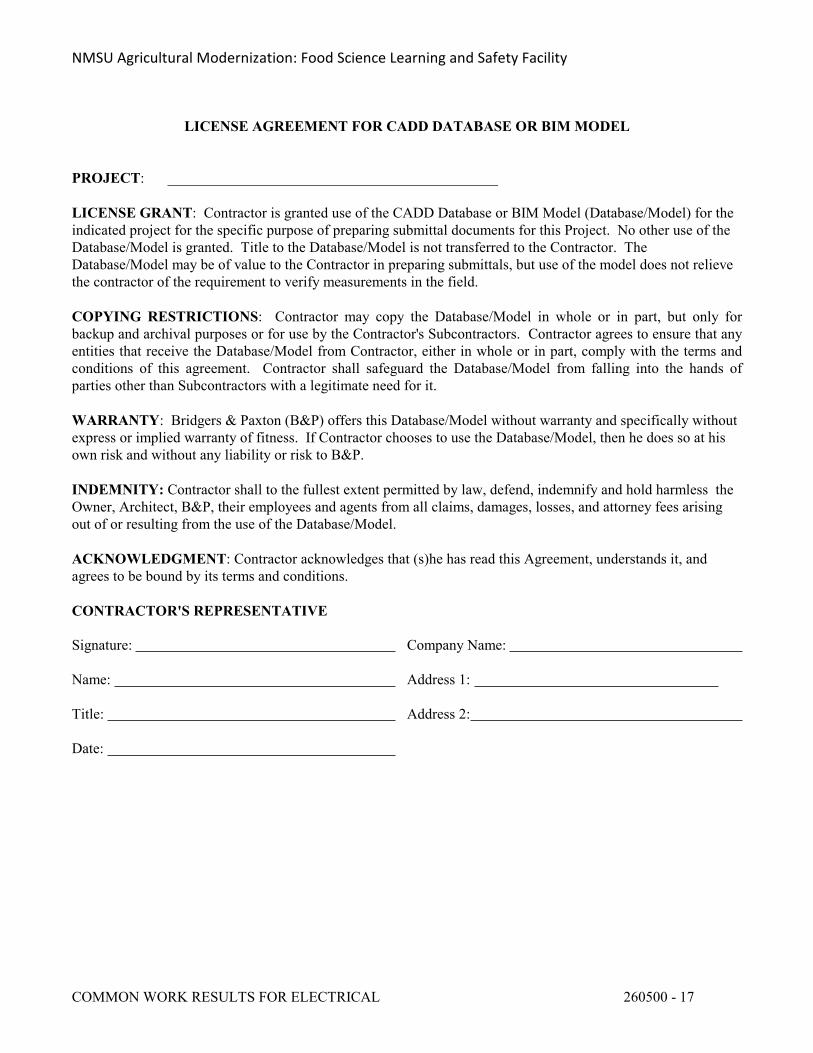
NMSU Agricultural Modernization: Food Science Learning and Safety Facility
COMMON WORK RESULTS FOR ELECTRICAL 260500 - 17
LICENSE AGREEMENT FOR CADD DATABASE OR BIM MODEL
PROJECT: _____________________________________________
LICENSE GRANT: Contractor is granted use of the CADD Database or BIM Model (Database/Model) for the indicated project for the specific purpose of preparing submittal documents for this Project. No other use of the Database/Model is granted. Title to the Database/Model is not transferred to the Contractor. The Database/Model may be of value to the Contractor in preparing submittals, but use of the model does not relieve the contractor of the requirement to verify measurements in the field.
COPYING RESTRICTIONS: Contractor may copy the Database/Model in whole or in part, but only for backup and archival purposes or for use by the Contractor's Subcontractors. Contractor agrees to ensure that any entities that receive the Database/Model from Contractor, either in whole or in part, comply with the terms and conditions of this agreement. Contractor shall safeguard the Database/Model from falling into the hands of parties other than Subcontractors with a legitimate need for it.
WARRANTY: Bridgers & Paxton (B&P) offers this Database/Model without warranty and specifically without express or implied warranty of fitness. If Contractor chooses to use the Database/Model, then he does so at his own risk and without any liability or risk to B&P.
INDEMNITY: Contractor shall to the fullest extent permitted by law, defend, indemnify and hold harmless the Owner, Architect, B&P, their employees and agents from all claims, damages, losses, and attorney fees arising out of or resulting from the use of the Database/Model.
ACKNOWLEDGMENT: Contractor acknowledges that (s)he has read this Agreement, understands it, and agrees to be bound by its terms and conditions.
CONTRACTOR'S REPRESENTATIVE
Signature: Company Name:
Name: Address 1:
Title: Address 2:
Date:
NMSU Agricultural Modernization: Food Science Learning and Safety Facility
MEDIUM VOLTAGE CABLES 260513 - 1
SECTION 260513 - MEDIUM VOLTAGE CABLES
PART 1 - GENERAL
1.1 RELATED DOCUMENTS
A. Drawings and general provisions of the Contract, including General and Supplementary Conditions and Division 1 Specification Sections, apply to this Section.
1.2 SUMMARY
A. This Section includes cables and related splices, terminations, and accessories for medium voltage electrical distribution systems.
B. Related Sections: The following Sections contain requirements that relate to this Section:
1. Division 26, Section 26 0529, Hangers and Supports for Electrical Systems for cable and termination supports.
2. Division 26, Section 26 0553, Identification Coordination for cable markers.
1.3 SUBMITTALS
A. Product data for cables and cable accessories, including splices and terminations.
B. Product certificate signed by manufacturer that its products comply with the specified requirements.
C. Qualification data for agencies and persons specified in "Quality Assurance" Article to demonstrate their capabilities and experience. Include list of completed projects with project names, addresses, names of Architects and Owners, and other information specified.
D. Product Test Reports: Certified reports of manufacturers' design and production tests indicating compliance of cable and accessories with referenced standards.
E. Field test reports indicating and interpreting test results relative to compliance with performance requirements specified. Include certified copies of field test records.
F. Maintenance data for cables and accessories to include in the "Operating and Maintenance Manual" specified in Division 1.
1. Include operation of fault indicators and separable insulated connectors and their accessories.
1.4 QUALITY ASSURANCE
NMSU Agricultural Modernization: Food Science Learning and Safety Facility
MEDIUM VOLTAGE CABLES 260513 - 2
A. Installer Qualifications: Engage an experienced and certified cable splicer to install, splice, and terminate medium-voltage cable.
B. Manufacturer Qualifications: Firm experienced in manufacturing medium-voltage cable and accessories similar to those indicated for this Project, with a record of successful in-service performance.
C. Testing Agency Qualifications: In addition to the requirements specified in Division 1 Section "Quality Control Services," an independent testing agency shall meet OSHA criteria for accreditation of testing laboratories, Title 29, Part 1907, or shall be a full member company of the International Electrical Testing Association (NETA).
1. Testing Agency's Field Supervisor Qualifications: A person currently certified by the NETA or National Institute for Certification in Engineering Technologies to supervise on-site testing specified in Part 3.
D. Comply with NFPA 70 National Electrical Code for components and installation.
E. Listing and Labeling: Provide products specified in this Section that are listed and labeled.
1. The Terms "Listed and Labeled": As defined in the "National Electrical Code," Article 100.
F. Single-Source Responsibility: All medium-voltage cable shall be the product of a single manufacturer.
1.5 DELIVERY, STORAGE, AND HANDLING
A. Deliver medium-voltage cable on factory reels complying with NEMA WC 26.
B. Store cables on reels on elevated platforms in a dry location.
PART 2 - PRODUCTS
2.1 MANUFACTURERS
A. Available Manufacturers: Subject to compliance with requirements, manufacturers offering products that may be incorporated in the Work include, but are not limited to, the following:
1. Cables:
a. The Okonite Co.b. Power Cable Division, Pirelli Cable Corp.c. Rome Cable Corp.d. Southwire Co.
NMSU Agricultural Modernization: Food Science Learning and Safety Facility
MEDIUM VOLTAGE CABLES 260513 - 3
2. Cable Splicing and Terminating Products and Accessories:
a. Cooper Power Systems, Inc., RTE Componentsb. Elastimoldc. G&W Electric Co.d. Energy Division, Raychem Corp.
2.2 CABLES
A. Type: MV90.
B. Conductor: Copper. C. Conductor Stranding: Compact.
D. Strand Filling: Convector interstices are filled with impermeable compound.
E. Insulation: Ethylene-propylene rubber (EPR) complying with AEIC CS6.
1. Voltage Rating: 15 kV.2. Insulation Thickness: 133 percent insulation level.
F. Shielding: Copper tape, helically applied over semiconducting insulation shield.
G. Shielding: Solid copper wires, helically applied over semi-conducting insulation shield.
H. Shielding and Jacket: Corrugated copper drain wires embedded in extruded chlorinated polyethylene jacket.
I. Jacket: Sunlight-resistant PVC.
2.3 SPLICE KITS
A. Connectors: IEEE 404, compression type, as recommended by cable or splicing kit manufacturer for the application.
B. Splicing Products: As recommended in writing by the splicing kit manufacturer for the specific sizes, ratings, and configurations of cable conductors and splices specified. Include all components required for complete splice, with detailed instructions.
1. Combination tape and cold-shrink rubber sleeve kit with rejacketing by cast-epoxy-resin encasement or other waterproof, abrasion-resistant material.
2. Heat-shrink splicing kit of uniform cross-section polymeric construction with outer heat-shrink jacket.
3. Premolded ethylene propylene diene monomer (EPDM) splicing body kit with cable joint sealed by interference fit of mating parts and cable.
2.4 SOLID TERMINATIONS
NMSU Agricultural Modernization: Food Science Learning and Safety Facility
MEDIUM VOLTAGE CABLES 260513 - 4
A. Conductor Terminations: Comply with IEEE Standard 48, as indicated. Insulation class equivalent to that of the cable. Terminations for shielded cables include a shield grounding strap.
1. Class 1 Termination for Shielded Cable: Modular type, furnished as a kit, with stress-relief tube, multiple molded silicone rubber insulator modules, shield ground strap, and compression-type connector.
2. Class 1 Termination for Shielded Cable: Heat-shrinkable type with heat-shrinkable inner stress control and outer nontracking tubes, multiple molded nontracking skirt modules, and compression-type connector.
3. Class 1 Termination for Shielded Cable: Modular type, furnished as a kit, with stress-relieving shield terminator; multiple-wet-process, porcelain, insulator modules; shield ground strap compression-type connector.
4. Class 2 Termination for Shielded Cable: Kit with stress-relief tube, nontracking insulator tube, shield ground strap, and compression-type connector. Include silicone rubber tape, cold-shrink rubber sleeve, or heat-shrink plastic sleeve moisture seal for end of insulation whether or not supplied with kits.
5. Class 3 Termination for Shielded Cable: Kit with stress cone and compression-type connector.
B. Termination for Nonshielded Cable: Kit with compression-type connector. Include silicone rubber tape, cold-shrink rubber sleeve, or heat-shrink plastic sleeve moisture seal for end of insulation whether or not supplied with kits.
2.5 SEPARABLE INSULATED CONNECTORS
A. Separable Insulated Connectors: Modular system complying with IEEE 386. Disconnecting, single-pole, cable terminators and matching stationary, plug-in, dead-front terminals designed for cable voltage and for sealing against moisture.
1. Terminations At Distribution Points: Modular type, consisting of terminators installed on cables and modular, dead-front, terminal junctions for interconnecting cables.
2. Load-Break Cable Terminators: Elbow-type units with 200-ampere load make/break and continuous current rating. Coordinate with insulation diameter and conductor size and material of cable being terminated. Include capacitively coupled test point on terminator body.
3. Dead-Break Cable Terminators: Elbow-type unit with 600-ampere continuous current rating, designed for deenergized disconnecting and connecting. Coordinated with insulation diameter and conductor size and material of cable being terminated. Include capacitively coupled test point on terminator body.
4. Dead-Front Terminal Junctions: Modular bracket-mounted groups of dead-front stationary terminals that mate and match with above cable terminators. Two-, three-, or four-terminal units as indicated, with fully rated, insulated, watertight conductor connection between terminals. Grounding lug and manufacturer's standard accessory stands and stainless-steel mounting brackets and attaching hardware.
5. Protective Cap: Insulating, electrostatic-shielding, water-sealing cap with drain wire.6. Portable Feed-Through Accessory: Two-terminal dead-front junction arranged for
NMSU Agricultural Modernization: Food Science Learning and Safety Facility
MEDIUM VOLTAGE CABLES 260513 - 5
removable mounting on accessory stand of stationary terminal junction.7. Grounding Kit: Jumpered elbows, portable feed-through accessory units, protective
caps, test rods suitable for concurrently grounding 3 phases of feeders, and carrying case.8. Standoff Insulator: Portable, single dead-front terminal for removable mounting on
accessory stand of stationary terminal junction. Insulators suitable for fully insulated isolation of energized cable elbow terminator.
9. Test Point Fault Indicators: Arranged for installation in test points of load-break separable connectors. Self-resetting indicators capable of being installed with a shotgun hot stick and tested with a test tool. Current trip ratings as indicated.
10. Tool Set: Shotgun-type hot stick with energized terminal indicator, fault indicator test tool, and carrying case.
2.6 ARC-PROOFING MATERIALS
A. Tape for First Course on Metal Objects: 10-mil-thick, corrosion-protective, moisture-resistant PVC pipe-wrapping tape.
B. Arc-Proofing Tape: NRTL-listed fireproofing tape, flexible, conformable, intumescent to 0.3 inch thick, and compatible with the cable jacket on which used.
C. Glass Cloth Tape: Pressure-sensitive adhesive type, 1/2 inch wide.
2.7 FAULT INDICATORS
A. Indicators: Manual reset, fault indicator, arranged to clamp to cable sheath and provide a display after the cable has faulted. Instrument immune to heat, moisture, and corrosive conditions and recommended by the manufacturer for the installation conditions. Indicators have current trip ratings and quantities as indicated.
B. Resetting Tool: Designed for use with fault indicators, with moisture-resistant storage/carrying case.
2.8 SOURCE QUALITY CONTROL
A. Test and inspect cables according to NEMA WC 8 before shipping.
B. Test strand filled cables for water-penetration resistance according to ICEA T-31-610, using a test pressure of 5 psig (35kPa).
PART 3 - EXECUTION
3.1 EXAMINATION
A. Examine raceways to receive medium-voltage cables for compliance with installation tolerances and other conditions affecting performance of the cable. Do not proceed with installation until unsatisfactory conditions have been corrected.
NMSU Agricultural Modernization: Food Science Learning and Safety Facility
MEDIUM VOLTAGE CABLES 260513 - 6
3.2 INSTALLATION
A. Install medium-voltage cable as indicated, according to manufacturer's written instructions and IEEE 576.
B. Pull conductors simultaneously where more than one cable is indicated in same raceway. Use NRTL-listed and manufacturer-approved pulling compound or lubricant where necessary. Do not exceed manufacturer's recommended maximum pulling tensions and sidewall pressure values.
C. Use pulling means including, fish tape, cable, rope, and basket-weave wire/cable grips that will not damage cables or raceways. Do not use rope hitches for pulling attachment to cable.
D. Install exposed cable parallel and perpendicular to surfaces of exposed structural members and follow surface contours where possible.
E. Install direct buried cable on a leveled and tamped 3-inch bed of clean sand at the bottom of trench. Install "buried cable" warning tape 12 inches above cable. Separate cables crossing other cables or piping from those items by a minimum of 4 inches of tamped earth. Install permanent markers at ends of cable runs, changes in direction, and buried splices.
F. In manholes, handholes, pull boxes, junction boxes, and cable vaults, train cables around walls by the longest route from entry to exit and support cables at intervals adequate to prevent sag.
G. Install splices at pull points and elsewhere as indicated using standard kit. Conform to kit manufacturer's written instructions.
H. Install terminations at ends of conductors and seal multiconductor cable ends with standard kits. Conform to manufacturer's written instructions. Comply with classes of terminations indicated.
I. Install separable insulated connector components where indicated in accordance with manufacturer's written instructions.
J. Quantities: Provide the following quantities of components:
1. Protective Cap: Install at each terminal junction, 1 on each terminal to which no feeder is indicated to be connected.
2. Portable Feed-Through Accessory: 3.3. Standoff Insulator: 3.
K. Arc-Proofing: Arc-proof medium-voltage cable at locations not protected by conduit, cable tray, direct burial, or termination materials except where indicated. Apply as follows and as recommended by the manufacturer of the arc-proofing tape.
1. Clean cable sheath.2. Wrap metallic cable components with 10-mil pipe wrapping tape.3. Smooth surface contours with electrical insulation putty.4. Apply arc-proofing tape in one half-lapped layer with the coated side toward the cable.
NMSU Agricultural Modernization: Food Science Learning and Safety Facility
MEDIUM VOLTAGE CABLES 260513 - 7
5. Band the arc-proofing tape with 1-inch -wide bands of half-lapped adhesive glass-cloth tape 2 inches on center.
L. Seal around cables passing through fire rated elements.
M. Fault Indicators: Install fault indicators on each phase where indicated.
3.3 GROUNDING
A. Ground shields of shielded cable at terminations, splices, and separable insulated connectors. Ground metal bodies of terminators, splices, cable and separable insulated connector fittings, and hardware according to manufacturer's written instructions.
3.4 IDENTIFICATION
A. Identify cable in accordance with Division 26, Section 26 0553, Identification for Electrical Systems.
3.5 FIELD QUALITY CONTROL
A. Testing Agency: Provide the services of a qualified independent testing agency to perform specified field quality-control testing.
B. Testing: Upon installation of medium-voltage cable and before electrical circuitry has been energized, demonstrate product capability and compliance with requirements.
1. Procedures: Perform each visual and mechanical inspection and electrical test stated in NETA Standard ATS, Section 7.3.2. Certify compliance with test parameters.
C. Correct malfunctioning units at site, where possible, and retest to demonstrate compliance; otherwise, remove and replace with new units, and retest.
3.6 PROTECTION
A. Provide final protection and maintain conditions, in a manner acceptable to Manufacturer and Installer, to prevent entrance of moisture into the cable and ensure that medium-voltage cable is without damage or deterioration at Substantial Completion.
END OF SECTION 260513
NMSU Agricultural Modernization: Food Science Learning and Safety Facility
LOW-VOLTAGE ELECTRICAL POWER CONDUCTORS AND CABLES 260519 - 1
SECTION 260519 - LOW-VOLTAGE ELECTRICAL POWER CONDUCTORS AND CABLES
PART 1 - GENERAL
1.1 RELATED DOCUMENTS
A. Drawings and general provisions of the Contract, including General and Supplementary Conditions and Division 01 Specification Sections, apply to this Section.
1.2 SUMMARY
A. Section Includes:
1. Building wires and cables rated 600 V and less.2. Connectors, splices, and terminations rated 600 V and less.
B. Related Requirements:
1. Section 26 0529 "Hangers and Supports for Electrical Systems” for supports and anchors for fastening cable directly to building finishes..
2. Section 26 0553 "Identification for Electrical Systems" for insulation color coding and wire cable markers.
1.3 DEFINITIONS
A. VFC: Variable frequency controller.
1.4 ACTION SUBMITTALS
A. Product Data: For each type of product.
1.5 INFORMATIONAL SUBMITTALS
A. Qualification Data: For testing agency.
B. Field quality-control reports.
1.6 QUALITY ASSURANCE
A. Testing Agency Qualifications: Member company of NETA or an NRTL.
1. Testing Agency's Field Supervisor: Certified by NETA to supervise on-site testing.
NMSU Agricultural Modernization: Food Science Learning and Safety Facility
LOW-VOLTAGE ELECTRICAL POWER CONDUCTORS AND CABLES 260519 - 2
PART 2 - PRODUCTS
2.1 CONDUCTORS AND CABLES
A. Manufacturers: Subject to compliance with requirements, provide products by one of the following:
1. Alcan Products Corporation; Alcan Cable Division.2. Alpha Wire.3. Belden Inc.4. Encore Wire Corporation.5. General Cable Technologies Corporation.6. Southwire Incorporated.
B. Copper Conductors: Comply with NEMA WC 70/ICEA S-95-658.
C. Conductor Insulation: Comply with NEMA WC 70/ICEA S-95-658 for Type XHHW-2.
D. Multi-conductor Cable: Metal Clad type “MC” cable not allowed.
2.2 CONNECTORS AND SPLICES
A. Manufacturers: Subject to compliance with requirements, provide products by one of the following:
1. AFC Cable Systems, Inc.2. Gardner Bender.3. Hubbell Power Systems, Inc.4. Ideal Industries, Inc.5. Ilsco; a branch of Bardes Corporation.6. NSi Industries LLC.7. O-Z/Gedney; a brand of the EGS Electrical Group.8. 3M; Electrical Markets Division.9. Tyco Electronics.
B. Description: Factory-fabricated connectors and splices of size, ampacity rating, material, type, and class for application and service indicated.
2.3 SYSTEM DESCRIPTION
A. Electrical Components, Devices, and Accessories: Listed and labeled as defined in NFPA 70, by a qualified testing agency, and marked for intended location and application.
B. Comply with NFPA 70.
NMSU Agricultural Modernization: Food Science Learning and Safety Facility
LOW-VOLTAGE ELECTRICAL POWER CONDUCTORS AND CABLES 260519 - 3
PART 3 - EXECUTION
3.1 CONDUCTOR MATERIAL APPLICATIONS
A. Feeders: Copper. Solid for No. 10 AWG and smaller; stranded for No. 8 AWG and larger.
B. Branch Circuits: Copper. Solid for No. 10 AWG and smaller; except VFC cable which shall be extra flexible stranded.
3.2 CONDUCTOR INSULATION AND MULTICONDUCTOR CABLE APPLICATIONS AND WIRING METHODS
A. Service Entrance: Type XHHW-2, single conductors in raceway.
B. Exposed Feeders: Not acceptable. All conductors in a raceway path.
C. Feeders Concealed in Ceilings, Walls, Partitions, and Crawlspaces: Type XHHW-2, single conductors in raceway.
D. Exposed Branch Circuits, Including in Crawlspaces: Type XHHW-2, single conductors in raceway.
E. Branch Circuits Concealed in Ceilings, Walls, and Partitions: Type XHHW-2 single conductors in raceway.
F. Cord Drops and Portable Appliance Connections: Type SO, hard service cord with stainless-steel, wire-mesh, and strain relief device at terminations to suit application.
3.3 INSTALLATION OF CONDUCTORS AND CABLES
A. Conceal cables in finished walls, ceilings, and floors unless otherwise indicated.
B. Complete raceway installation between conductor and cable termination points according to Section 26 0533 "Raceways and Boxes for Electrical Systems" prior to pulling conductors and cables.
C. Use manufacturer-approved pulling compound or lubricant where necessary; compound used must not deteriorate conductor or insulation. Do not exceed manufacturer's recommended maximum pulling tensions and sidewall pressure values.
D. Use pulling means, including fish tape, cable, rope, and basket-weave wire/cable grips, that will not damage cables or raceway.
E. Install exposed cables parallel and perpendicular to surfaces of exposed structural members, and follow surface contours where possible.
F. Support cables according to Section 26 05 29 "Hangers and Supports for Electrical Systems."
NMSU Agricultural Modernization: Food Science Learning and Safety Facility
LOW-VOLTAGE ELECTRICAL POWER CONDUCTORS AND CABLES 260519 - 4
G. Complete cable tray systems installation according to Section 26 05 36 "Cable Trays for Electrical Systems" prior to installing conductors and cables.
3.4 CONNECTIONS
A. Tighten electrical connectors and terminals according to manufacturer's published torque-tightening values. If manufacturer's torque values are not indicated, use those specified in UL 486A-486B.
B. Make splices, terminations, and taps that are compatible with conductor material and that possess equivalent or better mechanical strength and insulation ratings than un-spliced conductors.
C. Wiring at Outlets: Install conductor at each outlet, with at least 12 inches (300 mm) of slack.
3.5 IDENTIFICATION
A. Identify and color-code conductors and cables according to Section 26 0553 "Identification for Electrical Systems."
B. Identify each spare conductor at each end with identity number and location of other end of conductor, and identify as spare conductor.
3.6 SLEEVE AND SLEEVE-SEAL INSTALLATION FOR ELECTRICAL PENETRATIONS
A. Install sleeves and sleeve seals at penetrations of exterior floor and wall assemblies. Comply with requirements in Section 26 05 44 "Sleeves and Sleeve Seals for Electrical Raceways and Cabling."
3.7 FIRESTOPPING
A. Apply firestopping to electrical penetrations of fire-rated floor and wall assemblies to restore original fire-resistance rating of assembly according to Section 07 8413 "Penetration Firestopping."
3.8 FIELD QUALITY CONTROL
A. Testing Agency: Engage a qualified testing agency to perform tests and inspections.
B. Manufacturer's Field Service: Engage a factory-authorized service representative to test and inspect components, assemblies, and equipment installations, including connections.
C. Perform the following tests and inspections with the assistance of a factory-authorized service representative:
NMSU Agricultural Modernization: Food Science Learning and Safety Facility
LOW-VOLTAGE ELECTRICAL POWER CONDUCTORS AND CABLES 260519 - 5
1. After installing conductors and cables and before electrical circuitry has been energized, test service entrance and feeder conductors.
2. Perform each visual and mechanical inspection and electrical test stated in NETA Acceptance Testing Specification. Certify compliance with test parameters.
3. Infrared Scanning: After Substantial Completion, but not more than 60 days after Final Acceptance, perform an infrared scan of each splice in conductors No. 3 AWG and larger. Remove box and equipment covers so splices are accessible to portable scanner. Correct deficiencies determined during the scan.
a. Follow-up Infrared Scanning: Perform an additional follow-up infrared scan of each splice 11 months after date of Substantial Completion.
b. Instrument: Use an infrared scanning device designed to measure temperature or to detect significant deviations from normal values. Provide calibration record for device.
c. Record of Infrared Scanning: Prepare a certified report that identifies splices checked and that describes scanning results. Include notation of deficiencies detected, remedial action taken, and observations after remedial action.
D. Test and Inspection Reports: Prepare a written report to record the following:
1. Procedures used.2. Results that comply with requirements.3. Results that do not comply with requirements and corrective action taken to achieve
compliance with requirements.
E. Cables will be considered defective if they do not pass tests and inspections.
END OF SECTION 260519
NMSU Agricultural Modernization: Food Science Learning and Safety Facility
GROUNDING AND BONDING FOR ELECTRICAL SYSTEMS 260526 - 1
SECTION 260526 - GROUNDING AND BONDING FOR ELECTRICAL SYSTEMS
PART 1 - GENERAL
1.1 RELATED DOCUMENTS
A. Drawings and general provisions of the Contract, including General and Supplementary Conditions and Division 01 Specification Sections, apply to this Section.
1.2 SUMMARY
A. Section includes grounding and bonding systems and equipment.
B. Section includes grounding and bonding systems and equipment, plus the following special applications:
1. Underground distribution grounding.2. Ground bonding common with lightning protection system.3. Foundation steel electrodes.
1.3 ACTION SUBMITTALS
A. Product Data: For each type of product indicated.
1.4 INFORMATIONAL SUBMITTALS
A. As-Built Data: Plans showing dimensioned as-built locations of grounding features specified in "Field Quality Control" Article, including the following:
1. Test wells.2. Ground rods.3. Ground rings.4. Grounding arrangements and connections for separately derived systems.
B. Qualification Data: For testing agency and testing agency's field supervisor.
C. Field quality-control reports.
1.5 CLOSEOUT SUBMITTALS
A. Operation and Maintenance Data: For grounding to include in emergency, operation, and maintenance manuals.
1. In addition to items specified in Section 017823 "Operation and Maintenance Data," include the following:

NMSU Agricultural Modernization: Food Science Learning and Safety Facility
GROUNDING AND BONDING FOR ELECTRICAL SYSTEMS 260526 - 2
a. Instructions for periodic testing and inspection of grounding features at grounding connections for separately derived systems based on NFPA 70B.1) Tests shall determine if ground-resistance or impedance values remain
within specified maximums, and instructions shall recommend corrective action if values do not.
2) Include recommended testing intervals.
1.6 QUALITY ASSURANCE
A. Testing Agency Qualifications: Member company of NETA or an NRTL.
1. Testing Agency's Field Supervisor: Certified by NETA to supervise on-site testing.
B. Electrical Components, Devices, and Accessories: Listed and labeled as defined in NFPA 70, by a qualified testing agency, and marked for intended location and application.
C. Comply with UL 467 for grounding and bonding materials and equipment.
PART 2 - PRODUCTS
2.1 MANUFACTURERS
A. Manufacturers: Subject to compliance with requirements, provide products by one of the following:
1. Burndy; Part of Hubbell Electrical Systems.2. Dossert; AFL Telecommunications LLC.3. ERICO International Corporation.4. Fushi Copperweld Inc.5. Galvan Industries, Inc.; Electrical Products Division, LLC.6. Harger Lightning and Grounding.7. ILSCO.8. O-Z/Gedney; A Brand of the EGS Electrical Group.9. Robbins Lightning, Inc.10. Siemens Power Transmission & Distribution, Inc.
2.2 SYSTEM DESCRIPTION
A. Electrical Components, Devices, and Accessories: Listed and labeled as defined in NFPA 70, by a qualified testing agency, and marked for intended location and application.
B. Comply with UL 467 for grounding and bonding materials and equipment.
2.3 CONDUCTORS
A. Insulated Conductors: Copper wire or cable insulated for 600 V unless otherwise required by applicable Code or authorities having jurisdiction.
NMSU Agricultural Modernization: Food Science Learning and Safety Facility
GROUNDING AND BONDING FOR ELECTRICAL SYSTEMS 260526 - 3
B. Bare Copper Conductors:
1. Solid Conductors: ASTM B 3.2. Stranded Conductors: ASTM B 8.3. Tinned Conductors: ASTM B 33.4. Bonding Cable: 28 kcmil, 14 strands of No. 17 AWG conductor, 1/4 inch (6 mm) in
diameter.5. Bonding Conductor: No. 4 or No. 6 AWG, stranded conductor.6. Bonding Jumper: Copper tape, braided conductors terminated with copper ferrules; 1-5/8
inches (41 mm) wide and 1/16 inch (1.6 mm) thick.
C. Grounding Bus: Predrilled rectangular bars of annealed copper, 1/4 by 4 inches (6.3 by 100 mm in cross section, with 9/32-inch (7.14-mm) holes spaced 1-1/8 inches (28 mm) apart. Stand-off insulators for mounting shall comply with UL 891 for use in switchboards, 600 V and shall be Lexan or PVC, impulse tested at 5000 V.
2.4 CONNECTORS
A. Listed and labeled by an NRTL acceptable to authorities having jurisdiction for applications in which used and for specific types, sizes, and combinations of conductors and other items connected.
B. Bolted Connectors for Conductors and Pipes: Copper or copper alloy.
C. Welded Connectors: Exothermic-welding kits of types recommended by kit manufacturer for materials being joined and installation conditions.
D. Bus-Bar Connectors: Mechanical type, cast silicon bronze, solderless compression-type wire terminals, and long-barrel, two-bolt connection to ground bus bar.
2.5 GROUNDING ELECTRODES
A. Ground Rods: Copper-clad sectional type; 5/8 by 96 inches (16 by 2400 mm).
B. Chemical-Enhanced Grounding Electrodes: Copper tube, straight or L-shaped, charged with nonhazardous electrolytic chemical salts.
1. Termination: Factory-attached No. 4/0 AWG bare conductor at least 48 inches (1200 mm) long.
2. Backfill Material: Electrode manufacturers recommended material.
NMSU Agricultural Modernization: Food Science Learning and Safety Facility
GROUNDING AND BONDING FOR ELECTRICAL SYSTEMS 260526 - 4
PART 3 - EXECUTION
3.1 APPLICATIONS
A. Conductors: Install solid conductor for No. 8 AWG and smaller, and stranded conductors for No. 6 AWG and larger unless otherwise indicated.
B. Underground Grounding Conductors: Install bare copper conductor, No. 2/0 AWG minimum.
1. Bury at least 24 inches (600 mm) below grade.2. Duct-Bank Grounding Conductor: Bury 12 inches (300 mm) above duct bank when
indicated as part of duct-bank installation.
C. Isolated Grounding Conductors: Green-colored insulation with continuous yellow stripe. On feeders with isolated ground, identify grounding conductor where visible to normal inspection, with alternating bands of green and yellow tape, with at least three bands of green and two bands of yellow.
D. Grounding Bus: Install in electrical equipment rooms, in rooms housing service equipment, and elsewhere as indicated.
1. Install bus horizontally, on insulated spacers 2 inches (50 mm) minimum from wall, 6 inches (150 mm) above finished floor unless otherwise indicated.
2. Where indicated on both sides of doorways, route bus up to top of door frame, across top of doorway, and down; connect to horizontal bus.
E. Conductor Terminations and Connections:
1. Pipe and Equipment Grounding Conductor Terminations: Bolted connectors.2. Underground Connections: Welded connectors except at test wells and as otherwise
indicated.3. Connections to Ground Rods at Test Wells: Bolted connectors.4. Connections to Structural Steel: Welded connectors.5. Connection at service entrance: Welded connectors6. Connection at main grounding buss: Welded Connectors
3.2 GROUNDING AT THE SERVICE
A. Equipment grounding conductors and grounding electrode conductors shall be connected to the ground bus. Install a main bonding jumper between the neutral and ground buses.
3.3 GROUNDING SEPARATELY DERIVED SYSTEMS
A. Generator: Install grounding electrode(s) at the generator location. The electrode shall be connected to the equipment grounding conductor and to the frame of the generator.
NMSU Agricultural Modernization: Food Science Learning and Safety Facility
GROUNDING AND BONDING FOR ELECTRICAL SYSTEMS 260526 - 5
3.4 EQUIPMENT GROUNDING
A. Install insulated equipment grounding conductors with all feeders and branch circuits.
B. Install insulated equipment grounding conductors with the following items, in addition to those required by NFPA 70:
1. Feeders and branch circuits.2. Lighting circuits.3. Receptacle circuits.4. Single-phase motor and appliance branch circuits.5. Three-phase motor and appliance branch circuits.6. Flexible raceway runs.7. Metal-clad cable runs.
C. Air-Duct Equipment Circuits: Install insulated equipment grounding conductor to duct-mounted electrical devices operating at 120 V and more, including air cleaners, heaters, dampers, humidifiers, and other duct electrical equipment. Bond conductor to each unit and to air duct and connected metallic piping.
D. Water Heater, Heat-Tracing, and Antifrost Heating Cables: Install a separate insulated equipment grounding conductor to each electric water heater and heat-tracing cable. Bond conductor to heater units, piping, connected equipment, and components.
E. Poles Supporting Outdoor Lighting Fixtures: Install grounding electrode and a separate insulated equipment grounding conductor in addition to grounding conductor installed with branch-circuit conductors.
3.5 INSTALLATION
A. Grounding Conductors: Route along shortest and straightest paths possible unless otherwise indicated or required by Code. Avoid obstructing access or placing conductors where they may be subjected to strain, impact, or damage.
B. Ground Rods: Drive rods until tops are 2 inches (50 mm) below finished floor or final grade unless otherwise indicated.
1. Interconnect ground rods with grounding electrode conductor below grade and as otherwise indicated. Make connections without exposing steel or damaging coating if any.
2. For grounding electrode system, install at least three rods spaced at least one-rod length from each other and located at least the same distance from other grounding electrodes, and connect to the service grounding electrode conductor.
C. Bonding Straps and Jumpers: Install in locations accessible for inspection and maintenance except where routed through short lengths of conduit.
1. Bonding to Structure: Bond straps directly to basic structure, taking care not to penetrate any adjacent parts. Building is existing and Bonding will require new straps or the utilization of existing if adequately sized.
NMSU Agricultural Modernization: Food Science Learning and Safety Facility
GROUNDING AND BONDING FOR ELECTRICAL SYSTEMS 260526 - 6
2. Bonding to Equipment Mounted on Vibration Isolation Hangers and Supports: Install bonding so vibration is not transmitted to rigidly mounted equipment. Both new and existing equipment.
3. Use exothermic-welded connectors for outdoor locations; if a disconnect-type connection is required, use a bolted clamp.
D. Grounding and Bonding for Piping:
1. Metal Water Service Pipe: Install insulated copper grounding conductors, in conduit, from building's main service equipment, or grounding bus, to main metal water service entrances to building. Connect grounding conductors to main metal water service pipes; use a bolted clamp connector or bolt a lug-type connector to a pipe flange by using one of the lug bolts of the flange. Where a dielectric main water fitting is installed, connect grounding conductor on street side of fitting. Bond metal grounding conductor conduit or sleeve to conductor at each end.
2. Water Meter Piping: Use braided-type bonding jumpers to electrically bypass water meters. Connect to pipe with a bolted connector.
3. Bond each aboveground portion of gas piping system downstream from equipment shutoff valve.
E. Bonding Interior Metal Ducts: Bond metal air ducts to equipment grounding conductors of associated fans, blowers, electric heaters, and air cleaners. Install bonding jumper to bond across flexible duct connections to achieve continuity.
3.6 FIELD QUALITY CONTROL
A. Testing Agency: Engage a qualified testing agency to perform tests and inspections.
B. Manufacturer's Field Service: Engage a factory-authorized service representative to inspect, test, and adjust components, assemblies, and equipment installations, including connections.
C. Perform tests and inspections.
1. Manufacturer's Field Service: Engage a factory-authorized service representative to inspect components, assemblies, and equipment installations, including connections, and to assist in testing.
D. Tests and Inspections:
1. After installing grounding system but before permanent electrical circuits have been energized, test for compliance with requirements.
2. Inspect physical and mechanical condition. Verify tightness of accessible, bolted, electrical connections with a calibrated torque wrench according to manufacturer's written instructions.
3. Test completed grounding system at each location where a maximum ground-resistance level is specified, at service disconnect enclosure grounding terminal, and at individual ground rods. Make tests at ground rods before any conductors are connected.
NMSU Agricultural Modernization: Food Science Learning and Safety Facility
GROUNDING AND BONDING FOR ELECTRICAL SYSTEMS 260526 - 7
a. Measure ground resistance no fewer than two full days after last trace of precipitation and without soil being moistened by any means other than natural drainage or seepage and without chemical treatment or other artificial means of reducing natural ground resistance.
b. Perform tests by fall-of-potential method according to IEEE 81.
4. Prepare dimensioned Drawings locating each test well, ground rod and ground-rod assembly, and other grounding electrodes. Identify each by letter in alphabetical order, and key to the record of tests and observations. Include the number of rods driven and their depth at each location, and include observations of weather and other phenomena that may affect test results. Describe measures taken to improve test results.
E. Grounding system will be considered defective if it does not pass tests and inspections.
F. Prepare test and inspection reports.
G. Report measured ground resistances that exceed the following values:
1. Power and Lighting Equipment or System with Capacity of 500 kVA and Less: 10 ohms.2. Power and Lighting Equipment or System with Capacity of 500 to 1000 kVA: 5 ohms.3. Power and Lighting Equipment or System with Capacity More Than 1000 kVA: 3 ohms.
H. Excessive Ground Resistance: If resistance to ground exceeds specified values, notify Architect promptly and include recommendations to reduce ground resistance.
END OF SECTION 260526
NMSU Agricultural Modernization: Food Science Learning and Safety Facility
HANGERS AND SUPPORTS FOR ELECTRICAL SYSTEMS 260529 - 1
SECTION 260529 - HANGERS AND SUPPORTS FOR ELECTRICAL SYSTEMS
PART 1 - GENERAL
1.1 RELATED DOCUMENTS
A. Drawings and general provisions of the Contract, including General and Supplementary Conditions and Division 01 Specification Sections, apply to this Section.
1.2 SUMMARY
A. This Section includes the following:
1. Hangers and supports for electrical equipment and systems.2. Construction requirements for concrete bases.
B. Related Sections include the following:
1. Section 26 0548 "Vibration and Seismic Controls for Electrical Systems" for products and installation requirements necessary for compliance with seismic criteria.
1.3 DEFINITIONS
A. EMT: Electrical metallic tubing.
B. IMC: Intermediate metal conduit.
C. RMC: Rigid metal conduit.
1.4 PERFORMANCE REQUIREMENTS
A. Delegated Design: Design supports for multiple raceways, including comprehensive engineering analysis by a qualified professional engineer, using performance requirements and design criteria indicated.
B. Design supports for multiple raceways capable of supporting combined weight of supported systems and its contents.
C. Design equipment supports capable of supporting combined operating weight of supported equipment and connected systems and components.
D. Rated Strength: Adequate in tension, shear, and pullout force to resist maximum loads calculated or imposed for this Project, with a minimum structural safety factor of five times the applied force.
NMSU Agricultural Modernization: Food Science Learning and Safety Facility
HANGERS AND SUPPORTS FOR ELECTRICAL SYSTEMS 260529 - 2
1.5 ACTION SUBMITTALS
A. Product Data: For the following:
1. Steel slotted support systems.2. Nonmetallic slotted support systems.
B. Shop Drawings: Signed and sealed by a qualified professional engineer. Show fabrication and installation details and include calculations for the following:
1. Trapeze hangers. Include Product Data for components.2. Steel slotted channel systems. Include Product Data for components.3. Nonmetallic slotted channel systems. Include Product Data for components.4. Equipment supports.
1.6 INFORMATIONAL SUBMITTALS
A. Welding certificates.
1.7 QUALITY ASSURANCE
A. Welding: Qualify procedures and personnel according to AWS D1.1/D1.1M, "Structural Welding Code - Steel."
B. Comply with NFPA 70.
1.8 COORDINATION
A. Coordinate size and location of concrete bases. Cast anchor-bolt inserts into bases. Concrete, reinforcement, and formwork requirements are specified together with concrete Specifications.
B. Coordinate installation of roof curbs, equipment supports, and roof penetrations. These items are specified in Section 077200 "Roof Accessories."
PART 2 - PRODUCTS
2.1 SUPPORT, ANCHORAGE, AND ATTACHMENT COMPONENTS
A. Steel Slotted Support Systems: Comply with MFMA-4, factory-fabricated components for field assembly.
1. Available Manufacturers: Subject to compliance with requirements, manufacturers offering products that may be incorporated into the Work include, but are not limited to, the following:
a. Allied Tube & Conduit.b. Cooper B-Line, Inc.; a division of Cooper Industries.
NMSU Agricultural Modernization: Food Science Learning and Safety Facility
HANGERS AND SUPPORTS FOR ELECTRICAL SYSTEMS 260529 - 3
c. ERICO International Corporation.d. GS Metals Corp.e. Thomas & Betts Corporation.f. Unistrut; Tyco International, Ltd.g. Wesanco, Inc.
2. Metallic Coatings: Hot-dip galvanized after fabrication and applied according to MFMA-4.
3. Nonmetallic Coatings: Manufacturer's standard PVC, polyurethane, or polyester coating applied according to MFMA-4.
4. Painted Coatings: Manufacturer's standard painted coating applied according to MFMA-4.
5. Channel Dimensions: Selected for applicable load criteria.
B. Raceway and Cable Supports: As described in NECA 1 and NECA 101.
C. Conduit and Cable Support Devices: Steel and malleable-iron hangers, clamps, and associated fittings, designed for types and sizes of raceway or cable to be supported.
D. Support for Conductors in Vertical Conduit: Factory-fabricated assembly consisting of threaded body and insulating wedging plug or plugs for non-armored electrical conductors or cables in riser conduits. Plugs shall have number, size, and shape of conductor gripping pieces as required to suit individual conductors or cables supported. Body shall be malleable iron.
E. Structural Steel for Fabricated Supports and Restraints: ASTM A 36/A 36M, steel plates, shapes, and bars; black and galvanized.
F. Mounting, Anchoring, and Attachment Components: Items for fastening electrical items or their supports to building surfaces include the following:
1. Powder-Actuated Fasteners: Threaded-steel stud, for use in hardened portland cement concrete, steel, or wood, with tension, shear, and pullout capacities appropriate for supported loads and building materials where used.
a. Manufacturers: Subject to compliance with requirements, provide products by one of the following:
1) Hilti Inc.2) ITW Ramset/Red Head; a division of Illinois Tool Works, Inc.3) MKT Fastening, LLC.4) Simpson Strong-Tie Co., Inc.; Masterset Fastening Systems Unit.
2. Mechanical-Expansion Anchors: Insert-wedge-type, zinc-coated steel, for use in hardened portland cement concrete with tension, shear, and pullout capacities appropriate for supported loads and building materials in which used.
a. Manufacturers: Subject to compliance with requirements, provide products by one of the following:
1) Cooper B-Line, Inc.; a division of Cooper Industries.
NMSU Agricultural Modernization: Food Science Learning and Safety Facility
HANGERS AND SUPPORTS FOR ELECTRICAL SYSTEMS 260529 - 4
2) Empire Tool and Manufacturing Co., Inc.3) Hilti Inc.4) ITW Ramset/Red Head; a division of Illinois Tool Works, Inc.5) MKT Fastening, LLC.
3. Concrete Inserts: Steel or malleable-iron, slotted support system units similar to MSS Type 18; complying with MFMA-4 or MSS SP-58.
4. Clamps for Attachment to Steel Structural Elements: MSS SP-58, type suitable for attached structural element.
5. Through Bolts: Structural type, hex head, and high strength. Comply with ASTM A 325.
6. Toggle Bolts: All-steel springhead type.7. Hanger Rods: Threaded steel.
2.2 FABRICATED METAL EQUIPMENT SUPPORT ASSEMBLIES
A. Description: Welded or bolted, structural-steel shapes, shop or field fabricated to fit dimensions of supported equipment.
B. Materials: Comply with requirements in Section 05 50 00 "Metal Fabrications" for steel shapes and plates.
PART 3 - EXECUTION
3.1 APPLICATION
A. Comply with NECA 1 and NECA 101 for application of hangers and supports for electrical equipment and systems except if requirements in this Section are stricter.
B. Maximum Support Spacing and Minimum Hanger Rod Size for Raceway: Space supports for EMT, IMC, and RMC as required by NFPA 70. Minimum rod size shall be 1/4 inch (6 mm) in diameter.
C. Multiple Raceways or Cables: Install trapeze-type supports fabricated with steel slotted support system, sized so capacity can be increased by at least 25 percent in future without exceeding specified design load limits.
1. Secure raceways and cables to these supports with single-bolt conduit clamps using spring friction action for retention in support channel.
D. Spring-steel clamps designed for supporting single conduits without bolts may be used for 1-1/2-inch (38-mm) and smaller raceways serving branch circuits and communication systems above suspended ceilings and for fastening raceways to trapeze supports.
3.2 SUPPORT INSTALLATION
A. Comply with NECA 1 and NECA 101 for installation requirements except as specified in this Article.
NMSU Agricultural Modernization: Food Science Learning and Safety Facility
HANGERS AND SUPPORTS FOR ELECTRICAL SYSTEMS 260529 - 5
B. Raceway Support Methods: In addition to methods described in NECA 1, EMT, IMC, and RMC may be supported by openings through structure members, as permitted in NFPA 70.
C. Strength of Support Assemblies: Where not indicated, select sizes of components so strength will be adequate to carry present and future static loads within specified loading limits. Minimum static design load used for strength determination shall be weight of supported components plus 200 lb (90 kg).
D. Mounting and Anchorage of Surface-Mounted Equipment and Components: Anchor and fasten electrical items and their supports to building structural elements by the following methods unless otherwise indicated by code:
1. To Wood: Fasten with lag screws or through bolts.2. To New Concrete: Bolt to concrete inserts.3. To Masonry: Approved toggle-type bolts on hollow masonry units and expansion anchor
fasteners on solid masonry units.4. To Existing Concrete: Expansion anchor fasteners.5. Instead of expansion anchors, powder-actuated driven threaded studs provided with lock
washers and nuts may be used in existing standard-weight concrete 4 inches (100 mm) thick or greater. Do not use for anchorage to lightweight-aggregate concrete or for slabs less than 4 inches (100 mm) thick.
6. To Steel: Spring-tension clamps.7. To Light Steel: Sheet metal screws.8. Items Mounted on Hollow Walls and Nonstructural Building Surfaces: Mount cabinets,
panelboards, disconnect switches, control enclosures, pull and junction boxes, transformers, and other devices on slotted-channel racks attached to substrate by means that meet seismic-restraint strength and anchorage requirements.
E. Drill holes for expansion anchors in concrete at locations and to depths that avoid reinforcing bars.
3.3 INSTALLATION OF FABRICATED METAL SUPPORTS
A. Comply with installation requirements in Section 05 5000 "Metal Fabrications" for site-fabricated metal supports.
B. Cut, fit, and place miscellaneous metal supports accurately in location, alignment, and elevation to support and anchor electrical materials and equipment.
C. Field Welding: Comply with AWS D1.1/D1.1M.
3.4 CONCRETE BASES
A. Construct concrete bases of dimensions indicated but not less than 4 inches (100 mm) larger in both directions than supported unit, and so anchors will be a minimum of 10 bolt diameters from edge of the base.
B. Use 3000-psi (20.7-MPa), 28-day compressive-strength concrete. Concrete materials, reinforcement, and placement requirements are specified in Section 03 3053 "Miscellaneous Cast-in-Place Concrete."
NMSU Agricultural Modernization: Food Science Learning and Safety Facility
HANGERS AND SUPPORTS FOR ELECTRICAL SYSTEMS 260529 - 6
C. Anchor equipment to concrete base.
1. Place and secure anchorage devices. Use supported equipment manufacturer's setting drawings, templates, diagrams, instructions, and directions furnished with items to be embedded.
2. Install anchor bolts to elevations required for proper attachment to supported equipment.3. Install anchor bolts according to anchor-bolt manufacturer's written instructions.
3.5 PAINTING
A. Touchup: Clean field welds and abraded areas of shop paint. Paint exposed areas immediately after erecting hangers and supports. Use same materials as used for shop painting. Comply with SSPC-PA 1 requirements for touching up field-painted surfaces.
1. Apply paint by brush or spray to provide minimum dry film thickness of 2.0 mils (0.05 mm).
B. Touchup: Comply with requirements in Section 099113 "Exterior Painting" and Section 09 91 23 "Interior Painting for cleaning and touchup painting of field welds, bolted connections, and abraded areas of shop paint on miscellaneous metal.
C. Galvanized Surfaces: Clean welds, bolted connections, and abraded areas and apply galvanizing-repair paint to comply with ASTM A 780.
END OF SECTION 260529
NMSU Agricultural Modernization: Food Science Learning and Safety Facility
RACEWAYS AND BOXES FOR ELECTRICAL SYSTEMS 260533 - 1
SECTION 260533 - RACEWAYS AND BOXES FOR ELECTRICAL SYSTEMS
PART 1 - GENERAL
1.1 RELATED DOCUMENTS
A. Drawings and general provisions of the Contract, including General and Supplementary Conditions and Division 01 Specification Sections, apply to this Section.
1.2 SUMMARY
A. Section Includes:
1. Metal conduits, tubing, and fittings.2. Nonmetal conduits, tubing, and fittings.3. Metal wireways and auxiliary gutters.4. Nonmetal wireways and auxiliary gutters.5. Surface raceways.6. Boxes, enclosures, and cabinets.7. Handholes and boxes for exterior underground cabling.
B. Related Requirements:
1. Section 26 0543 "Underground Ducts and Raceways for Electrical Systems" for exterior ductbanks, manholes, and underground utility construction.
2. Section 27 0528 "Pathways for Communications Systems" for conduits, wireways, surface pathways, innerduct, boxes, faceplate adapters, enclosures, cabinets, and handholes serving communications systems.
3. Section 28 0528 "Pathways for Electronic Safety and Security" for conduits, surface pathways, innerduct, boxes, and faceplate adapters serving electronic safety and security.
1.3 DEFINITIONS
A. ARC: Aluminum rigid conduit.
B. GRC: Galvanized rigid steel conduit
C. IMC: Intermediate metal conduit.
1.4 ACTION SUBMITTALS
A. Product Data: For surface raceways, wireways and fittings, floor boxes, hinged-cover enclosures, and cabinets.
B. LEED Submittals:
NMSU Agricultural Modernization: Food Science Learning and Safety Facility
RACEWAYS AND BOXES FOR ELECTRICAL SYSTEMS 260533 - 2
1. Product Data for Credit IEQ 4.1: For solvent cements and adhesive primers, documentation including printed statement of VOC content.
2. Laboratory Test Reports for Credit IEQ 4: For solvent cements and adhesive primers, documentation indicating that products comply with the testing and product requirements of the California Department of Health Services' "Standard Practice for the Testing of Volatile Organic Emissions from Various Sources Using Small-Scale Environmental Chambers."
C. Shop Drawings: For custom enclosures and cabinets. Include plans, elevations, sections, and attachment details.
1.5 INFORMATIONAL SUBMITTALS
A. Coordination Drawings: Conduit routing plans, drawn to scale, on which the following items are shown and coordinated with each other, using input from installers of items involved:
1. Structural members in paths of conduit groups with common supports.2. HVAC and plumbing items and architectural features in paths of conduit groups with
common supports.
B. Qualification Data: For professional engineer.
C. Seismic Qualification Certificates: For enclosures, cabinets, and conduit racks and their mounting provisions including those for internal components, from manufacturer.
1. Basis for Certification: Indicate whether withstand certification is based on actual test of assembled components or on calculation.
2. Dimensioned Outline Drawings of Equipment Unit: Identify center of gravity and locate and describe mounting and anchorage provisions.
3. Detailed description of equipment anchorage devices on which the certification is based and their installation requirements.
4. Detailed description of conduit support devices and interconnections on which the certification is based and their installation requirements.
D. Source quality-control reports.
PART 2 - PRODUCTS
2.1 METAL CONDUITS, TUBING, AND FITTINGS
A. Manufacturers: Subject to compliance with requirements, provide products by one of the following, but are not limited to, the following:
1. AFC Cable Systems, Inc.2. Allied Tube & Conduit.3. Anamet Electrical, Inc.4. Electri-Flex Company.
NMSU Agricultural Modernization: Food Science Learning and Safety Facility
RACEWAYS AND BOXES FOR ELECTRICAL SYSTEMS 260533 - 3
5. O-Z/Gedney.6. Picoma Industries.7. Republic Conduit.8. Robroy Industries.9. Southwire Company.10. Thomas & Betts Corporation.11. Western Tube and Conduit Corporation.12. Wheatland Tube Company.
B. Listing and Labeling: Metal conduits, tubing, and fittings shall be listed and labeled as defined in NFPA 70, by a qualified testing agency, and marked for intended location and application.
C. GRC: Comply with ANSI C80.1 and UL 6.
D. ARC: Comply with ANSI C80.5 and UL 6A.
E. IMC: Comply with ANSI C80.6 and UL 1242.
F. PVC-Coated Steel Conduit: PVC-coated rigid steel conduit.1. Comply with NEMA RN 1.2. Coating Thickness: 0.040 inch (1 mm), minimum.
G. EMT: Comply with ANSI C80.3 and UL 797.
H. FMC: Comply with UL 1; zinc-coated steel.
I. LFMC: Flexible steel conduit with PVC jacket and complying with UL 360.
J. Fittings for Metal Conduit: Comply with NEMA FB 1 and UL 514B
1. Conduit Fittings for Hazardous (Classified) Locations: Comply with UL 886 and NFPA 70.
2. Fittings for EMT:
a. Material: Steel.b. Type: compression.
3. Expansion Fittings: PVC or steel to match conduit type, complying with UL 651, rated for environmental conditions where installed, and including flexible external bonding jumper.
4. Coating for Fittings for PVC-Coated Conduit: Minimum thickness of 0.040 inch (1 mm), with overlapping sleeves protecting threaded joints.
K. Joint Compound for IMC, GRC, or ARC: Approved, as defined in NFPA 70, by authorities having jurisdiction for use in conduit assemblies, and compounded for use to lubricate and protect threaded conduit joints from corrosion and to enhance their conductivity.
NMSU Agricultural Modernization: Food Science Learning and Safety Facility
RACEWAYS AND BOXES FOR ELECTRICAL SYSTEMS 260533 - 4
2.2 NONMETALLIC CONDUITS, TUBING, AND FITTINGS
A. Manufacturers: Subject to compliance with requirements, provide products by one of the following, but are not limited to, the following:
1. AFC Cable Systems, Inc.2. Anamet Electrical, Inc.3. Arnco Corporation.4. CANTEX Inc.5. CertainTeed Corporation.6. Condux International, Inc.7. Electri-Flex Company.8. Kraloy.9. Lamson & Sessions; Carlon Electrical Products.10. Niedax-Kleinhuis USA, Inc.11. RACO; Hubbell.12. Thomas & Betts Corporation.
B. Listing and Labeling: Nonmetallic conduits, tubing, and fittings shall be listed and labeled as defined in NFPA 70, by a qualified testing agency, and marked for intended location and application.
C. ENT: Comply with NEMA TC 13 and UL 1653.
D. RNC: Type EPC-40-PVC, complying with NEMA TC 2 and UL 651 unless otherwise indicated.
E. LFNC: Comply with UL 1660.
F. Rigid HDPE: Comply with UL 651A.
G. Continuous HDPE: Comply with UL 651B.
H. Coilable HDPE: Preassembled with conductors or cables, and complying with ASTM D 3485.
I. RTRC: Comply with UL 1684A and NEMA TC 14.
J. Fittings for ENT and RNC: Comply with NEMA TC 3; match to conduit or tubing type and material.
K. Fittings for LFNC: Comply with UL 514B.
L. Solvent cements and adhesive primers shall have a VOC content of 510 and 550 g/L or less, respectively, when calculated according to 40 CFR 59, Subpart D (EPA Method 24).
M. Solvent cements and adhesive primers shall comply with the testing and product requirements of the California Department of Health Services' "Standard Practice for the Testing of Volatile Organic Emissions from Various Sources Using Small-Scale Environmental Chambers."
NMSU Agricultural Modernization: Food Science Learning and Safety Facility
RACEWAYS AND BOXES FOR ELECTRICAL SYSTEMS 260533 - 5
2.3 METAL WIREWAYS AND AUXILIARY GUTTERS
A. Manufacturers: Subject to compliance with requirements provide products by one of the following, but are not limited to, the following:
1. Cooper B-Line, Inc.2. Hoffman.3. Mono-Systems, Inc.4. Square D.
B. Description: Sheet metal, complying with UL 870 and NEMA 250, Type 1 unless otherwise indicated, and sized according to NFPA 70.
1. Metal wireways installed outdoors shall be listed and labeled as defined in NFPA 70, by a qualified testing agency, and marked for intended location and application.
C. Fittings and Accessories: Include covers, couplings, offsets, elbows, expansion joints, adapters, hold-down straps, end caps, and other fittings to match and mate with wireways as required for complete system.
D. Wireway Covers: Screw-cover type unless otherwise indicated.
E. Finish: Manufacturer's standard enamel finish.
2.4 NONMETALLIC WIREWAYS AND AUXILIARY GUTTERS
A. Manufacturers: Subject to compliance with requirements, provide products by one of the following, but are not limited to, the following:
1. Allied Moulded Products, Inc.2. Hoffman.3. Lamson & Sessions; Carlon Electrical Products.4. Niedax-Kleinhuis USA, Inc.
B. Listing and Labeling: Nonmetallic wireways and auxiliary gutters shall be listed and labeled as defined in NFPA 70, by a qualified testing agency, and marked for intended location and application.
C. Description: Fiberglass polyester, extruded and fabricated to required size and shape, without holes or knockouts. Cover shall be gasketed with oil-resistant gasket material and fastened with captive screws treated for corrosion resistance. Connections shall be flanged and have stainless-steel screws and oil-resistant gaskets.
D. Description: PVC, extruded and fabricated to required size and shape, and having snap-on cover, mechanically coupled connections, and plastic fasteners. Fittings and Accessories: Couplings, offsets, elbows, expansion joints, adapters, hold-down straps, end caps, and other fittings shall match and mate with wireways as required for complete system.
NMSU Agricultural Modernization: Food Science Learning and Safety Facility
RACEWAYS AND BOXES FOR ELECTRICAL SYSTEMS 260533 - 6
E. Solvent cements and adhesive primers shall have a VOC content of 510 and 550 g/L or less, respectively, when calculated according to 40 CFR 59, Subpart D (EPA Method 24).
F. Solvent cements and adhesive primers shall comply with the testing and product requirements of the California Department of Health Services' "Standard Practice for the Testing of Volatile Organic Emissions from Various Sources Using Small-Scale Environmental Chambers."
2.5 SURFACE RACEWAYS
A. Listing and Labeling: Surface raceways and tele-power poles shall be listed and labeled as defined in NFPA 70, by a qualified testing agency, and marked for intended location and application.
B. Surface Metal Raceways: Galvanized steel with snap-on covers complying with UL 5. Prime coated, ready for field painting.
1. Manufacturers: Subject to compliance with requirements provide products by one of the following, but are not limited to, the following:
a. Mono-Systems, Inc.b. Panduit Corp.c. Wiremold / Legrand.
C. Surface Nonmetallic Raceways: Two- or three-piece construction, complying with UL 5A, and manufactured of rigid PVC with texture and color selected by Architect from manufacturer's standard colors. Product shall comply with UL 94 V-0 requirements for self-extinguishing characteristics
1. Manufacturers: Subject to compliance with requirements, provide products by one of the following, but are not limited to, the following:
a. Hubbell Incorporated.b. Mono-Systems, Inc.c. Panduit Corp.d. Wiremold / Legrand.
D. Tele-Power Poles:
1. Manufacturers: Subject to compliance with requirements, provide products by one of the following, but are not limited to, the following:
a. Mono-Systems, Inc.b. Panduit Corp.c. Wiremold / Legrand.
2. Material: Galvanized steel with ivory baked-enamel finish.3. Fittings and Accessories: Dividers, end caps, covers, cutouts, wiring harnesses, devices,
mounting materials, and other fittings shall match and mate with tele-power pole as required for complete system.
NMSU Agricultural Modernization: Food Science Learning and Safety Facility
RACEWAYS AND BOXES FOR ELECTRICAL SYSTEMS 260533 - 7
2.6 BOXES, ENCLOSURES, AND CABINETS
A. Manufacturers: Subject to compliance with requirements provide products by one of the following:
1. Wiremold / Legrand2. Adalet.3. Cooper Technologies Company; Cooper Crouse-Hinds.4. EGS/Appleton Electric.5. Erickson Electrical Equipment Company.6. FSR Inc.7. Hoffman.8. Hubbell Incorporated.9. Kraloy.10. Milbank Manufacturing Co.11. Mono-Systems, Inc.12. O-Z/Gedney.13. RACO; Hubbell.14. Robroy Industries.15. Spring City Electrical Manufacturing Company.16. Stahlin Non-Metallic Enclosures.17. Thomas & Betts Corporation.
B. General Requirements for Boxes, Enclosures, and Cabinets: Boxes, enclosures, and cabinets installed in wet locations shall be listed for use in wet locations.
C. Sheet Metal Outlet and Device Boxes: Comply with NEMA OS 1 and UL 514A.
D. Cast-Metal Outlet and Device Boxes: Comply with NEMA FB 1, ferrous alloy, Type FD, with gasketed cover.
E. Nonmetallic Outlet and Device Boxes: Comply with NEMA OS 2 and UL 514C.
F. Metal Floor Boxes:
1. Material: Cast metal.2. Type: Fully adjustable.3. Shape: Rectangular.4. Listing and Labeling: Metal floor boxes shall be listed and labeled as defined in
NFPA 70, by a qualified testing agency, and marked for intended location and application.
G. Nonmetallic Floor Boxes: Nonadjustable, rectangular.
1. Listing and Labeling: Nonmetallic floor boxes shall be listed and labeled as defined in NFPA 70, by a qualified testing agency, and marked for intended location and application.
NMSU Agricultural Modernization: Food Science Learning and Safety Facility
RACEWAYS AND BOXES FOR ELECTRICAL SYSTEMS 260533 - 8
H. Luminaire Outlet Boxes: Nonadjustable, designed for attachment of luminaire weighing 50 lb (23 kg). Outlet boxes designed for attachment of luminaires weighing more than 50 lb (23 kg) shall be listed and marked for the maximum allowable weight.
I. Paddle Fan Outlet Boxes: Nonadjustable, designed for attachment of paddle fan weighing 70 lb (32 kg).
1. Listing and Labeling: Paddle fan outlet boxes shall be listed and labeled as defined in NFPA 70, by a qualified testing agency, and marked for intended location and application.
J. Small Sheet Metal Pull and Junction Boxes: NEMA OS 1.
K. Cast-Metal Access, Pull, and Junction Boxes: Comply with NEMA FB 1 and UL 1773, cast aluminum with gasketed cover.
L. Box extensions used to accommodate new building finishes shall be of same material as recessed box.
M. Device Box Dimensions: 4 inches square by 2-1/8 inches deep (100 mm square by 60 mm deep.
N. Gangable boxes are allowed up to a four devices.
O. Hinged-Cover Enclosures: Comply with UL 50 and NEMA 250, Type 1 with continuous-hinge cover with flush latch unless otherwise indicated.
1. Metal Enclosures: Steel, finished inside and out with manufacturer's standard enamel.2. Nonmetallic Enclosures: Fiberglass.3. Interior Panels: Steel; all sides finished with manufacturer's standard enamel.
P. Cabinets:
1. NEMA 250, Type 1 galvanized-steel box with removable interior panel and removable front, finished inside and out with manufacturer's standard enamel.
2. Hinged door in door front cover with flush latch and concealed hinge.3. Key latch to match panelboards.4. Metal barriers to separate wiring of different systems and voltage.5. Accessory feet where required for freestanding equipment.6. Nonmetallic cabinets shall be listed and labeled as defined in NFPA 70, by a qualified
testing agency, and marked for intended location and application.
PART 3 - EXECUTION
3.1 RACEWAY APPLICATION
A. Outdoors: Apply raceway products as specified below unless otherwise indicated:
1. Exposed Conduit: GRC.
NMSU Agricultural Modernization: Food Science Learning and Safety Facility
RACEWAYS AND BOXES FOR ELECTRICAL SYSTEMS 260533 - 9
2. Concealed Conduit, Aboveground: GRC, IMC, and EMT.3. Underground Conduit: RNC, Type EPC-40-PVC, concrete encased.4. Connection to Vibrating Equipment (Including Transformers and Hydraulic, Pneumatic,
Electric Solenoid, or Motor-Driven Equipment): LFMC.5. Boxes and Enclosures, Aboveground: NEMA 250, Type 3R.
B. Indoors: Apply raceway products as specified below unless otherwise indicated:
1. Exposed, Not Subject to Physical Damage: EMT.2. Exposed, Not Subject to Severe Physical Damage: EMT.3. Exposed and Subject to Severe Physical Damage: GRC. Raceway locations include the
following:
a. Loading dock.b. Corridors used for traffic of mechanized carts, forklifts, and pallet-handling units.c. Mechanical rooms.
4. Concealed in Ceilings and Interior Walls and Partitions: EMT.5. Connection to Vibrating Equipment (Including Transformers and Hydraulic, Pneumatic,
Electric Solenoid, or Motor-Driven Equipment): FMC, except use LFMC in damp or wet locations.
6. Damp or Wet Locations: GRC.7. Boxes and Enclosures: NEMA 250, Type 1, except use NEMA 250, Type 4 stainless
steel in institutional and commercial kitchens and damp or wet locations.
C. Minimum Raceway Size: 3/4-inch trade size.
D. Raceway Fittings: Compatible with raceways and suitable for use and location.
1. Rigid and Intermediate Steel Conduit: Use threaded rigid steel conduit fittings unless otherwise indicated. Comply with NEMA FB 2.10.
2. PVC Externally Coated, Rigid Steel Conduits: Use only fittings listed for use with this type of conduit. Patch and seal all joints, nicks, and scrapes in PVC coating after installing conduits and fittings. Use sealants recommended by fitting manufacturer and apply in thickness and number of coats recommended by manufacturer.
3. EMT: Use compression, fittings. Comply with NEMA FB 2.10.4. Flexible Conduit: Use only fittings listed for use with flexible conduit. Comply with
NEMA FB 2.20.
E. Install nonferrous conduit or tubing for circuits operating above 60 Hz. Where aluminum raceways are installed for such circuits and pass through concrete, install in nonmetallic sleeve.
F. Do not install aluminum conduits, boxes, or fittings in contact with concrete or earth.
G. Install surface raceways only where indicated on Drawings.
H. Do not install nonmetallic conduit where ambient temperature exceeds 120 deg F (49 deg C).
NMSU Agricultural Modernization: Food Science Learning and Safety Facility
RACEWAYS AND BOXES FOR ELECTRICAL SYSTEMS 260533 - 10
3.2 INSTALLATION
A. Comply with NECA 1 and NECA 101 for installation requirements except where requirements on Drawings or in this article are stricter. Comply with NECA 102 for aluminum conduits. Comply with NFPA 70 limitations for types of raceways allowed in specific occupancies and number of floors.
B. Keep raceways at least 6 inches (150 mm) away from parallel runs of flues and steam or hot-water pipes. Install horizontal raceway runs above water and steam piping.
C. Complete raceway installation before starting conductor installation.
D. Comply with requirements in Section 26 05 29 "Hangers and Supports for Electrical Systems" for hangers and supports.
E. Arrange stub-ups so curved portions of bends are not visible above finished slab.
F. Install no more than the equivalent of three 90-degree bends in any conduit run except for control wiring conduits, for which fewer bends are allowed. Support within 12 inches (300 mm) of changes in direction.
G. Conceal conduit and EMT within finished walls, ceilings, and floors unless otherwise indicated. Install conduits parallel or perpendicular to building lines.
H. Support conduit within 12 inches (300 mm) of enclosures to which attached.
I. Stub-ups to Above Recessed Ceilings:
1. Use EMT, IMC, or RMC for raceways.2. Use a conduit bushing or insulated fitting to terminate stub-ups not terminated in hubs or
in an enclosure.
J. Threaded Conduit Joints, Exposed to Wet, Damp, Corrosive, or Outdoor Conditions: Apply listed compound to threads of raceway and fittings before making up joints. Follow compound manufacturer's written instructions.
K. Coat field-cut threads on PVC-coated raceway with a corrosion-preventing conductive compound prior to assembly.
L. Raceway Terminations at Locations Subject to Moisture or Vibration: Use insulating bushings to protect conductors including conductors smaller than No. 4 AWG.
M. Terminate threaded conduits into threaded hubs or with locknuts on inside and outside of boxes or cabinets. Install bushings on conduits up to 1-1/4-inch (35mm) trade size and insulated throat metal bushings on 1-1/2-inch (41-mm) trade size and larger conduits terminated with locknuts. Install insulated throat metal grounding bushings on service conduits.
N. Install raceways square to the enclosure and terminate at enclosures with locknuts. Install locknuts hand tight plus 1/4 turn more.
NMSU Agricultural Modernization: Food Science Learning and Safety Facility
RACEWAYS AND BOXES FOR ELECTRICAL SYSTEMS 260533 - 11
O. Do not rely on locknuts to penetrate nonconductive coatings on enclosures. Remove coatings in the locknut area prior to assembling conduit to enclosure to assure a continuous ground path.
P. Cut conduit perpendicular to the length. For conduits 2-inch (53-mm) trade size and larger, use roll cutter or a guide to make cut straight and perpendicular to the length.
Q. Install pull wires in empty raceways. Use polypropylene or monofilament plastic line with not less than 200-lb (90-kg) tensile strength. Leave at least 12 inches (300 mm) of slack at each end of pull wire. Cap underground raceways designated as spare above grade alongside raceways in use.
R. Surface Raceways:
1. Install surface raceway with a minimum 2-inch (50-mm) radius control at bend points.2. Secure surface raceway with screws or other anchor-type devices at intervals not
exceeding 48 inches (1200 mm) and with no less than two supports per straight raceway section. Support surface raceway according to manufacturer's written instructions. Tape and glue are not acceptable support methods.
3. Exterior surface raceways to be painted to match exterior boxes, gear, enclosures, etc. Typically this will be color DESERT TAN. Verify with architect and owner prior to painting.
S. Install raceway sealing fittings at accessible locations according to NFPA 70 and fill them with listed sealing compound. For concealed raceways, install each fitting in a flush steel box with a blank cover plate having a finish similar to that of adjacent plates or surfaces. Install raceway sealing fittings according to NFPA 70.
T. Install devices to seal raceway interiors at accessible locations. Locate seals so no fittings or boxes are between the seal and the following changes of environments. Seal the interior of all raceways at the following points:
1. Where conduits pass from warm to cold locations, such as boundaries of refrigerated spaces.
2. Where an underground service raceway enters a building or structure.3. Where otherwise required by NFPA 70.
U. Comply with manufacturer's written instructions for solvent welding RNC and fittings.
V. Expansion-Joint Fittings:
1. Install in each run of aboveground RNC that is located where environmental temperature change may exceed 30 deg F (17 deg C) and that has straight-run length that exceeds 25 feet (7.6 m). Install in each run of aboveground RMC and EMT conduit that is located where environmental temperature change may exceed 100 deg F (55 deg C) and that has straight-run length that exceeds 100 feet (30 m).
2. Install type and quantity of fittings that accommodate temperature change listed for each of the following locations:
a. Outdoor Locations Not Exposed to Direct Sunlight: 125 deg F (70 deg C) temperature change.
NMSU Agricultural Modernization: Food Science Learning and Safety Facility
RACEWAYS AND BOXES FOR ELECTRICAL SYSTEMS 260533 - 12
b. Outdoor Locations Exposed to Direct Sunlight: 155 deg F (86 deg C temperature change.
c. Indoor Spaces Connected with Outdoors without Physical Separation: 125 deg F (70 deg C) temperature change.
d. Attics: 135 deg F (75 deg C) temperature change.
3. Install fitting(s) that provide expansion and contraction for at least 0.000078 inch per foot of length of straight run per deg F (0.0115 mm per meter of length of straight run per deg C) of temperature change for metal conduits.
4. Install expansion fittings at all locations where conduits cross building or structure expansion joints.
5. Install each expansion-joint fitting with position, mounting, and piston setting selected according to manufacturer's written instructions for conditions at specific location at time of installation. Install conduit supports to allow for expansion movement.
W. Flexible Conduit Connections: Comply with NEMA RV 3. Use a maximum of 72 inches (1830 mm) of flexible conduit for recessed and semi-recessed luminaires, equipment subject to vibration, noise transmission, or movement; and for transformers and motors.
1. Use LFMC in damp or wet locations subject to severe physical damage.2. Use LFMC or LFNC in damp or wet locations not subject to severe physical damage.
X. Mount boxes at heights indicated on Drawings. If mounting heights of boxes are not individually indicated, give priority to ADA requirements. Install boxes with height measured to top of box unless otherwise indicated.
Y. Recessed Boxes in Masonry Walls: Saw-cut opening for box in center of cell of masonry block, and install box flush with surface of wall. Prepare block surfaces to provide a flat surface for a raintight connection between box and cover plate or supported equipment and box.
Z. Horizontally separate boxes mounted on opposite sides of walls so they are not in the same vertical channel.
AA. Locate boxes so that cover or plate will not span different building finishes.
BB. Support boxes from more than one side by spanning two framing members or mounting on brackets specifically designed for the purpose.
CC. Fasten junction and pull boxes to or support from building structure. Do not support boxes by conduits.
DD. Set metal floor boxes level and flush with finished floor surface.
EE. Set nonmetallic floor boxes level. Trim after installation to fit flush with finished floor surface.
3.3 INSTALLATION OF UNDERGROUND CONDUIT
A. Direct-Buried Conduit:
NMSU Agricultural Modernization: Food Science Learning and Safety Facility
RACEWAYS AND BOXES FOR ELECTRICAL SYSTEMS 260533 - 13
1. Excavate trench bottom to provide firm and uniform support for conduit. Prepare trench bottom as specified in Section 31 20 00 "Earth Moving" for pipe less than 6 inches (150 mm) in nominal diameter.
2. Install backfill as specified in Section 31 20 00 "Earth Moving."3. After installing conduit, backfill and compact. Start at tie-in point, and work toward end
of conduit run, leaving conduit at end of run free to move with expansion and contraction as temperature changes during this process. Firmly hand tamp backfill around conduit to provide maximum supporting strength. After placing controlled backfill to within 12 inches (300 mm) of finished grade, make final conduit connection at end of run and complete backfilling with normal compaction as specified in Section 312000 "Earth Moving."
4. Install manufactured duct elbows for stub-ups at poles and equipment and at building entrances through floor unless otherwise indicated. Encase elbows for stub-up ducts throughout length of elbow.
5. Install manufactured rigid steel conduit elbows for stub-ups at poles and equipment and at building entrances through floor.
a. Couple steel conduits to ducts with adapters designed for this purpose, and encase coupling with 3 inches (75 mm) of concrete for a minimum of 12 inches (300 mm) on each side of the coupling.
b. For stub-ups at equipment mounted on outdoor concrete bases and where conduits penetrate building foundations, extend steel conduit horizontally a minimum of 60 inches (1500 mm) from edge of foundation or equipment base. Install insulated grounding bushings on terminations at equipment.
6. Warning Planks: Bury warning planks approximately 12 inches (300 mm) above direct-buried conduits but a minimum of 6 inches (150 mm) below grade. Align planks along centerline of conduit.
7. Underground Warning Tape: Comply with requirements in Section 260553 "Identification for Electrical Systems."
3.4 SLEEVE AND SLEEVE-SEAL INSTALLATION FOR ELECTRICAL PENETRATIONS
A. Install sleeves and sleeve seals at penetrations of exterior floor and wall assemblies. Comply with requirements in Section 26 05 44 "Sleeves and Sleeve Seals for Electrical Raceways and Cabling."
3.5 FIRESTOPPING
A. Install firestopping at penetrations of fire-rated floor and wall assemblies. Comply with requirements in Section 07 84 13 "Penetration Firestopping."
NMSU Agricultural Modernization: Food Science Learning and Safety Facility
RACEWAYS AND BOXES FOR ELECTRICAL SYSTEMS 260533 - 14
3.6 PROTECTION
A. Protect coatings, finishes, and cabinets from damage and deterioration.
1. Repair damage to galvanized finishes with zinc-rich paint recommended by manufacturer.
2. Repair damage to PVC coatings or paint finishes with matching touchup coating recommended by manufacturer.
END OF SECTION 260533
NMSU Agricultural Modernization: Food Science Learning and Safety Facility
CABLE TRAYS 260536 - 1
SECTION 260536 – CABLE TRAYS
PART 1 - GENERAL
1.1 RELATED DOCUMENTS
A. Drawings and general provisions of the Contract, including General and Supplementary Conditions and Division 1 Specification Sections, apply to this Section.
1.2 SUMMARY
A. This Section includes cable trays and accessories.
B. Related Sections include the following:
1. Division 7, Section Firestopping for firestopping materials and installation requirements.2. Division 26, Section 26 0529, Hangers and Supports for Electrical Systems for cable tray
supports not specified in this Section.
1.3 SUBMITTALS
A. Product Data: Include data indicating dimensions and finishes for each type of cable tray.
B. Shop Drawings: Detail fabrication and installation of cable tray, including plans, elevations, and sections of components and attachments to other construction elements. Designate components and accessories, including clamps, brackets, hanger rods, splice-plate connectors, expansion-joint assemblies, straight lengths, and fittings.
C. Design Calculations: Verify loading capacities for supports.
D. Coordination Drawings: Include floor plans and sections drawn to scale. Include scaled cable tray layout and relationships between components and adjacent structural and mechanical elements.
E. Factory-certified test reports of specified products, complying with NEMA VE 1.
F. Field Test Reports: Indicate and interpret test results for compliance with performance requirements specified in "Field Quality Control" Article.
G. Maintenance Data: For cable trays to include in the maintenance manuals specified in Division 1.
1.4 QUALITY ASSURANCE
A. Source Limitations: Obtain cable tray components through one source from a single manufacturer.
NMSU Agricultural Modernization: Food Science Learning and Safety Facility
CABLE TRAYS 260536 - 2
B. Listing and Labeling: Provide cable trays and accessories specified in this Section that are listed and labeled.
1. The Terms "Listed" and "Labeled": As defined in NFPA 70, Article 100.
C. Comply with NEMA VE 1, Metal Cable Tray Systems, for materials, sizes, and configurations.
D. Comply with NFPA 70.
1.5 PROJECT CONDITIONS
A. Existing Utilities: Do not interrupt utilities serving facilities occupied by the Owner or others unless permitted under the following conditions and then only after arranging to provide temporary utility services according to requirements indicated.
B. Notify Architect not less than 2 days in advance of proposed utility interruptions.
C. Do not proceed with utility interruptions without Architect's written permission.
1.6 COORDINATION
A. Coordinate layout and installation of cable tray with other installations.
1. Revise locations and elevations from those indicated as required to suit field conditions and as approved by Architect.
PART 2 - PRODUCTS
2.1 MANUFACTURERS
A. Available Manufacturers: Subject to compliance with requirements, manufacturers offering products that may be incorporated into the Work include, but are not limited to, the following:
B. Manufacturers: Subject to compliance with requirements, provide products by one of the following:
1. B-Line Systems, Inc.2. Chalfant Cable Trays.3. GS Metals Corp.4. Husky: MP Husky Corp.5. Mono-Systems, Inc.6. P-W Industries, Inc.
2.2 MATERIALS AND FINISHES
A. Cable Trays, Fittings, and Accessories: Steel, hot-dip galvanized after fabrication, complying with ASTM A 123, Class B2.
NMSU Agricultural Modernization: Food Science Learning and Safety Facility
CABLE TRAYS 260536 - 3
B. Cable Trays, Fittings, and Accessories: Aluminum, complying with Aluminum Association's alloy 6063-T6 for rails, rungs, and cable trays, and alloy 5052-H32 or 6061-T6 for fabricated parts.
C. Protect steel hardware against corrosion by galvanizing according to ASTM B 633 or cadmium plating according to ASTM B 766.
D. Fabricate cable tray products with rounded edges and smooth surfaces.
E. Sizes and Configurations: Refer to Cable Tray Requirments on Drawings for specific requirements for types, materials, sizes, and configurations.
2.3 CABLE TRAY ACCESSORIES
A. Fittings: Tees, crosses, risers, elbows, and other fittings as indicated, of same materials and finishes as cable tray.
B. Cable tray supports and connectors, including bonding jumpers, as recommended by cable tray manufacturer.
2.4 WARNING SIGNS
A. Lettering: 1-1/2-inch high, black letters on yellow background with legend "WARNING! NOT TO BE USED AS WALKWAY, LADDER, OR SUPPORT FOR LADDERS OR PERSONNEL."
B. Materials and fastening are specified in Division 26, Section 26 0553, Identification for Electrical Systems.
C. Materials and fastening are specified in Division 26, Section 26 0501, Common Work Results for Electrical.
2.5 SOURCE QUALITY CONTROL
A. Perform design and production tests according to NEMA VE 1.
PART 3 - EXECUTION
3.1 EXAMINATION
A. Examine substrates for compliance with requirements for installation tolerances and other conditions affecting performance of cable trays. Do not proceed with installation until unsatisfactory conditions have been corrected.
3.2 INSTALLATION
NMSU Agricultural Modernization: Food Science Learning and Safety Facility
CABLE TRAYS 260536 - 4
A. Install cable tray level and plumb according to manufacturer's written instructions, Coordination Drawings, original design, and referenced standards.
B. Remove burrs and sharp edges from cable trays.
C. Fasten cable tray supports securely to building structure as specified in Division 26 unless otherwise indicated.
1. Locate and install supports according to NEMA VE 1.2. Design supports, including fastenings to the structure, to carry the greater of the
calculated load multiplied by a safety factor of 4 or the calculated load plus 200 lb.
D. Make connections to equipment with flanged fittings fastened to cable tray and to equipment. Support cable tray independently of fittings. Do not carry weight of cable tray on equipment enclosure.
E. Install expansion connectors where cable tray crosses a building expansion joint and in cable tray runs that exceed 90 feet. Space connectors and set gaps according to NEMA VE 1.
F. Make changes in direction and elevation using standard fittings.
G. Make cable tray connections using standard fittings.
H. Locate cable tray above lay-in ceiling (except in lab areas), unless accessibility to cable tray is required or unless otherwise indicated. Refer to drawings for cable tray requirements.
I. Seal penetrations through fire and smoke barriers according to Division 7 Section Firestopping.
J. Sleeves for Future Cables: Install capped sleeves for future cables through firestopping-sealed cable tray penetrations of fire and smoke barriers.
K. Workspace: Install cable trays with sufficient space to permit access for installing cables.
3.3 CONNECTIONS
A. Ground cable trays according to manufacturer's instructions.
1. Tighten electrical connectors and terminals according to manufacturer's published torque-tightening values. Where manufacturer's torque values are not indicated, use those specified in UL 486A and UL 486B.
3.4 WARNING SIGNS
A. After installation of cable trays is completed, install warning signs in visible locations on or near cable trays.
3.5 FIELD QUALITY CONTROL
NMSU Agricultural Modernization: Food Science Learning and Safety Facility
CABLE TRAYS 260536 - 5
A. Grounding: Test cable trays to ensure electrical continuity of bonding and grounding connections.
B. Anchorage: Test pullout resistance for toggle bolts and powder-driven threaded studs for each type and size of anchorage material.
1. Furnish equipment, including jacks, jigs, fixtures, and calibrated indicating scales, required for reliable testing.
2. Obtain Architect's approval before transmitting loads to the structure. Test to 90 percent of rated proof load for fastener.
C. Replace malfunctioning units.
3.6 CLEANING
A. On completion of cable tray installation, including fittings, inspect exposed finish. Remove burrs, dirt, and construction debris and repair damaged finishes, including chips, scratches and abrasions.
3.7 PROTECTION
A. Provide final protection and maintain conditions, in a manner acceptable to manufacturer and installer that ensure cable tray is without damage or deterioration at the time of Substantial completion.
1. Repair damage to galvanized finishes with zinc-rich paint recommended by cable tray manufacturer.
B. Repair damage to PVC or paint finishes with matching touchup coating recommended by cable tray manufacturer.
END OF SECTION 260536
NMSU Agricultural Modernization: Food Science Learning and Safety Facility
UNDERGROUND DUCTS AND RACEWAYS 260543 - 1
SECTION 260543 – UNDERGROUND DUCTS AND RACEWAYS
PART 1 - GENERAL
1.1 RELATED DOCUMENTS
A. Drawings and general provisions of the Contract, including General and Supplementary Conditions and Division 1 Specifications Sections, apply to this section.
1.2 SUMMARY
A. This Section includes the following:
1. Ducts in direct buried duct banks.2. Ducts in concrete encased duct banks.3. Handholes and handhole accessories.
B. Related Sections include the following:
1. Division 26, Section 26 0526, Grounding and Bonding for Electrical Systems for grounding electrodes, counterpoise conductors, clamps and connectors for grounding metallic manhole and handhole accessories, and testing of grounds.
1.3 SUBMITTALS
A. Product Data: For the following:
1. Manhole and handhole hardware.2. Conduit and ducts, including elbows, bell ends, bends, fittings, and solvent cement.3. Duct bank materials, including spacers and miscellaneous components.4. Warning tape.
B. Shop Drawings: Show fabrication and installation details for underground ducts and utility structures and include the following:
1. For manholes:
a. Duct sizes and locations of duct entries.b. Reinforcement details.c. Manhole cover design.d. Step details.e. Grounding details.f. Dimensioned locations of cable rack inserts, pulling-in irons, and sumps.
2. For precast manholes and handholes, shop drawings shall be signed and sealed by a qualified professional engineer and shall show the following:
NMSU Agricultural Modernization: Food Science Learning and Safety Facility
UNDERGROUND DUCTS AND RACEWAYS 260543 - 2
a. Construction of individual segments.b. Joint details.c. Design calculations.
C. Coordination Drawings: Show duct profiles and coordination with other utilities and underground structures. Include plans and sections drawn to scale, and show all bends and location of expansion fittings.
D. Product Certificates: For concrete and steel used in underground precast manholes, according to ASTM C 858.
E. Product Test Reports: Indicate compliance of manholes with ASTM C 857 and ASTM C 858, based on factory inspection.
1.4 QUALITY ASSURANCE
A. Electrical Components, Devices, and Accessories: Listed and labeled as defined in NFP A 70, Article 100, by a testing agency acceptable to authorities having jurisdiction, and marked for intended use.
B. Comply with ANSI C2.
C. Comply with NFPA 70.
1.5 DELIVERY, STORAGE AND HANDLING
A. Deliver ducts to project site with ends capped. Store nonmetallic ducts with supports to prevent bending, warping, and deforming.
B. Store precast concrete units at project site as recommended by manufacturer to prevent physical damage. Arrange so identification markings are visible.
C. Lift and support precast concrete units only at designated lifting or supporting points.
1.6 PROJECT CONDITIONS
A. Existing Utilities: Do not interrupt utilities serving facilities occupied by Owner or others unless permitted under the following conditions and then only after arranging to provide temporary utility services according to requirements indicated.
1. Notify Architect as least two (2) days in advance of proposed utility interruptions.2. Do not proceed with utility interruptions without Architect’s written permission.
NMSU Agricultural Modernization: Food Science Learning and Safety Facility
UNDERGROUND DUCTS AND RACEWAYS 260543 - 3
1.7 COORDINATION
A. Coordinate layout and installation of ducts, manholes, and handholes with final arrangement of other utilities and site grading, as determined in the field.
B. Coordinate elevations of ducts and duct bank entrances into manholes and handholes with final profiles of conduits as determined by coordination with other utilities and underground obstructions. Revise locations and elevations from those indicated as required to suit field conditions and to ensure duct runs drain to manholes and handholes, and as approved by Architect.
PART 2 - PRODUCTS
2.1 PRODUCTS AND MANUFACTURERS
A. Available Manufacturers: Subject to compliance with requirements, manufacturers offering products that may be incorporated into the work include, but are not limited to, the following:
B. Manufacturers: Subject to compliance with requirements, provide products by one of the following:
1. Underground Precast Concrete Utility Structures:
a. Brooks Products, Inc.b. Carder Concrete Productsc. Christy Concrete Products, Inc.d. Elmhurst-Chicago Stone Companye. Riverton Concrete Productsf. Rotondo Precast/Old Castleg. Utility Vault Companyh. Wausau Concrete Company
2. Frames and Covers:
a. Campbell Foundry Companyb. East Jordan Iron Works, Inc.c. Mckinley Iron Works, Inc.d. Neenah Foundry Company
3. Nonmetallic Ducts and Accessories:
a. Arnco Corporationb. Beck Manufacturing Inc.c. Cantex, Inc.d. Certainteed Corporation, Pipe & Plastics Groupe. ElecSys, Inc.f. Electri-Flex Company
NMSU Agricultural Modernization: Food Science Learning and Safety Facility
UNDERGROUND DUCTS AND RACEWAYS 260543 - 4
g. Ipex, Inc.h. Lamson & Sessions; Carlon Electrical Productsi. Manhattan/CDT/Cole-Flexj. Spiraduct/AFC Cable Systems, Inc.
2.2 CONDUIT
A. Conduit and fittings are specified in Division 26, Section 26 0533, Raceways and Boxes for Electrical Systems.
2.3 DUCTS
A. Rigid Nonmetallic Conduit: NEMA TC 2, Type EPC-40-PVC, UL 651, with matching fittings by the same manufacturer as the conduit, complying with NEMA TC 3 and 514B.
2.4 HANDHOLES
A. Cast Metal Boxes: Cast aluminum, with outside flanges and recessed, gasketed cover for flush mounting and with nonskid finish and legend on cover. Unit, when buried, shall be designed to support AASHTO H10 loading.
B. Precast Handholes: Reinforced concrete, monolithically poured walls and bottom, with steel frame and access door assembly as the top of handhole. Duct entrances and windows shall be located near corners to facilitate racking. Pulling-in irons and other built-in items shall be installed before pouring concrete. Cover shall have nonskid finish and legend. Unit, when buried, shall be designed to support AASHTO H10 loading.
C. Fiberglass Handholes: Molded fiberglass, with 6-inch square cable entrance at each side and weatherproof cover with nonskid finish and legend. Unit, when buried, shall be designed to support AASHTO H10 loading.
D. Cover Legend: 'ELECTRIC.'
PART 3 - EXECUTION
3.1 APPLICATION
A. Underground Ducts for Electrical Cables Higher than 600V: Type EPC-40-PVC, concrete-encased duct bank.
B. Underground Ducts for Electrical Branch Circuits: Type DB-60-PVC, direct buried duct bank.
3.2 EARTHWORK
NMSU Agricultural Modernization: Food Science Learning and Safety Facility
UNDERGROUND DUCTS AND RACEWAYS 260543 - 5
A. Excavation and Backfill: Comply with Division 2 Section, Earthwork, but do not use heavy duty hydraulic operated, compaction equipment. The entire depth of trench shall be backfilled in 12 inch layers, and each layer shall be moistened and compacted to 95% below any walks, paving or structures and to 90% in open areas. Compaction shall be based on Standard Proctor Tests conducted on the materials used.
B. Restore surface features at areas disturbed by excavation and re-establish original grades, unless otherwise indicated. Replace removed sod immediately after backfilling is completed.
C. Restore all areas disturbed by trenching, storing of dirt, cable laying, and other work. Restore vegetation and include necessary topsoiling, fertilizing, liming, seeding, sodding, sprigging, and mulching. Comply with Division 2 Section 'Landscaping.'
D. Restore disturbed pavement. Refer to Division 1 Section, Cutting and Patching.
3.3 CONDUIT AND DUCT INSTALLATION
A. Slope: Pitch ducts a minimum slop of 1:300 down toward manholes and handholes and away from buildings and equipment. Slope ducts from a high point in runs between two (2) manholes to drain in both directions.
B. Curves and Bends: Use manufactured elbows for stub-ups at equipment and at building entrances. Use manufactured long sweep bends with a minimum radius of 25 feet, both horizontally and vertically, at other locations.
C. Use solvent cement joints in ducts and fittings and make watertight according to manufacturer’s written instructions. Stagger couplings so those of adjacent ducts do not lie in the same plane.
D. Duct Entrances to Manholes and Handholes: Space end bells approximately 10 inches o.c. for 5 inch ducts and vary proportionately for other duct sizes. Change from regular spacing to end bell spacing 10 feet from the end bell without reducing duct line slope and without forming a trap in the line. Grout end bells into manhole walls from both sides to provide watertight entrances.
E. Building Entrances: Make a transition from underground duct to conduit at least ten feet outside the building wall. Use fittings manufactured for this purpose. Follow the appropriate installation instructions below.
1. Concrete Encased Ducts: Install reinforcement in duct banks passing through disturbed earth near buildings and other excavations. Coordinate duct bank with structural design to support duct bank at wall without reducing structural or watertight integrity of building wall.
2. Direct Buried, Nonencased Ducts at Nonwaterproofed Wall Penetrations: Install a Schedule 40, galvanized steel pipe sleeve for each duct. Calk space between conduit and sleeve with duct sealing compound on both sides for moisture tight seal.
3. Waterproofed Wall and Floor Penetrations: Install a watertight entrance sealing device with sealing gland assembly on the inside. Anchor device into masonry construction with one or more integral flanges. Secure membrane waterproofing to the device to
NMSU Agricultural Modernization: Food Science Learning and Safety Facility
UNDERGROUND DUCTS AND RACEWAYS 260543 - 6
make permanently watertight.
F. Concrete Encased, Nonmetallic Ducts: Support ducts on duct spacers, spaced as recommended by manufacturer and coordinated with duct size, duct spacing and outdoor temperature. Install as follows:
1. Separator Installation: Space separators close enough to prevent sagging and deforming of ducts and secure separators to earth and to ducts to prevent floating during concreting. Stagger spacers approximately 6-inches between tiers. Tie entire assembly together using fabric straps; do not use tie wires or reinforcing steel that may form conductive or magnetic loops around ducts or duct groups.
2. Concreting: Spade concrete carefully during pours to prevent voids under and between conduits and at exterior surface of envelope. Do not allow a heavy mass of concrete to fall directly onto ducts. Use a plank to direct concrete down sides of bank assembly to trench bottom. Allow concrete to flow to center of bank and rise up in middle, uniformly filling all open spaces. Do not use power driven agitating equipment unless specifically designed for duct bank application. Pour each run of envelope between manholes or other terminations in one continuous operation. If more than one pour is necessary, terminate each pour in a vertical plane and install 3/4 inch reinforcing rod dowels extending 18 inches into concrete on both sides of joint near corners of envelope.
3. Reinforcement: Reinforce duct banks where they cross disturbed earth and where indicated.
4. Forms: Use walls of trench to form side walls of duct bank where soil is self supporting and concrete envelope can be poured without soil inclusions; otherwise, use forms.
5. Minimum Clearances Between Ducts: Three (3) inches between ducts and exterior envelope wall, two (2) inches between ducts for like services, and four (4) inches between power and signal ducts.
6. Depth: Install top of duct bank at least 24 inches below finished grade in nontraffic areas and at least 30 inches below finished grade in vehicular traffic areas, unless otherwise indicated.
G. Direct Buried Ducts: Support ducts on duct spacers, spaced as recommended by manufacturer and coordinated with duct size, duct spacing, and outdoor temperature. Install as follows:
1. Separator Installation: Space separators close enough to prevent sagging and deforming of ducts.
2. Install expansion fittings as shown on shop drawings.3. Trench Bottom: Continuous, firm, and uniform support for duct bank. Prepare trench
bottoms as specified in Division 2, Section, Earthwork for pipes less than 6 inches in nominal diameter.
4. Backfill: Install backfill as specified in Division 2, Section, Earthwork. After installing first tier of ducts, backfill and compact. Repeat backfilling after placing each tier. After placing last tier, hand place backfill to 4 inches over ducts and hand tamp. Firmly tamp backfill around ducts to provide maximum supporting strength. Use hand temper only. After placing controlled backfill over final tier, complete backfilling normally.
5. Minimum Clearances Between Ducts: Three (3) inches between ducts for like services and six (6) inches between power and signal ducts.
6. Depth: Install top of duct bank at least 36 inches below finished grade, unless otherwise indicated.
NMSU Agricultural Modernization: Food Science Learning and Safety Facility
UNDERGROUND DUCTS AND RACEWAYS 260543 - 7
H. Warning Tape: Bury warning tape approximately 12 inches above all concrete encased duct banks. Align tape parallel to and within 3 inches of the centerline of duct bank.
I. Stub Ups: Use rigid steel conduit for stub ups to equipment. For equipment mounted on outdoor concrete bases, extend steel conduit a minimum of 5 feet from edge of base. Install insulated grounding bushings on terminations. Couple steel conduits to ducts with adapters designed for this purpose and encase coupling with 3 inches of concrete.
J. Sealing: Provide temporary closure at terminations of ducts that have cables pulled. Seal spare ducts at terminations. Use sealing compound and plugs to withstand at least 15 PSIG hydrostatic pressure.
K. Pulling Cord: Install 100 lbf test nylon cord in ducts, including spares.
3.4 MANHOLE AND HANDHOLE INSTALLATION
A. Elevation: Install hand holes with depth as indicated. Where indicated, cast handhole cover frame directly into roof of handhole and set roof surface one (1) inch above grade.
3.5 FIELD QUALITY CONTROL
A. Testing: Demonstrate capability and compliance with requirements on completion of installation of underground ducts and utility structures.
B. Duct Integrity: Pull aluminum or wood test mandrel through duct to prove joint integrity and test for out-of-round duct. Provide mandrel equal to 80% fill of the duct. If obstructions are indicated, remove obstructions and retest.
C. Correct installations if possible and retest to demonstrate compliance. Remove and replace defective products and retest.
3.6 CLEANING
A. Pull leather washer type duct cleaner, with graduated washer sizes, through full length of ducts. Follow with rubber duct swab for final cleaning and to assist in spreading lubricant throughout ducts.
B. Clean internal surfaces of manholes, including sump. Remove foreign material.
END OF SECTION 260543
NMSU Agricultural Modernization: Food Science Learning and Safety Facility
IDENTIFICATION FOR ELECTRICAL SYSTEMS 260553 - 1
SECTION 260553 - IDENTIFICATION FOR ELECTRICAL SYSTEMS
PART 1 - GENERAL
1.1 RELATED DOCUMENTS
A. Drawings and general provisions of the Contract, including General and Supplementary Conditions and Division 01 Specification Sections, apply to this Section.
1.2 SUMMARY
A. Section Includes:
1. Identification for raceways.2. Identification of power and control cables.3. Identification for conductors.4. Underground-line warning tape.5. Warning labels and signs.6. Instruction signs.7. Equipment identification labels.8. Miscellaneous identification products.
1.3 ACTION SUBMITTALS
A. Product Data: For each electrical identification product indicated.
B. Samples: For each type of label and sign to illustrate size, colors, lettering style, mounting provisions, and graphic features of identification products.
C. Identification Schedule: An index of nomenclature of electrical equipment and system components used in identification signs and labels.
1.4 QUALITY ASSURANCE
A. Comply with ANSI A13.1 and IEEE C2.
B. Comply with NFPA 70.
C. Comply with 29 CFR 1910.144 and 29 CFR 1910.145.
D. Comply with ANSI Z535.4 for safety signs and labels.
E. Adhesive-attached labeling materials, including label stocks, laminating adhesives, and inks used by label printers, shall comply with UL 969.
NMSU Agricultural Modernization: Food Science Learning and Safety Facility
IDENTIFICATION FOR ELECTRICAL SYSTEMS 260553 - 2
1.5 COORDINATION
A. Coordinate identification names, abbreviations, colors, and other features with requirements in other Sections requiring identification applications, Drawings, Shop Drawings, manufacturer's wiring diagrams, and the Operation and Maintenance Manual; and with those required by codes, standards, and 29 CFR 1910.145. Use consistent designations throughout Project.
B. Coordinate installation of identifying devices with completion of covering and painting of surfaces where devices are to be applied.
C. Coordinate installation of identifying devices with location of access panels and doors.
D. Install identifying devices before installing acoustical ceilings and similar concealment.
PART 2 - PRODUCTS
2.1 POWER AND CONTROL RACEWAY IDENTIFICATION MATERIALS
A. Comply with ANSI A13.1 for minimum size of letters for legend and for minimum length of color field for each raceway size.
B. Colors for Raceways Carrying Circuits at 600 V or Less:
1. Black letters on an orange field.2. Legend: Indicate voltage and system or service type.
C. Vinyl Labels for Raceways Carrying Circuits at 600 V or Less: Preprinted, flexible label laminated with a clear, weather- and chemical-resistant coating and matching wraparound clear adhesive tape for securing ends of legend label.
D. Snap-Around Labels for Raceways Carrying Circuits at 600 V or Less: Slit, pretensioned, flexible, preprinted, color-coded acrylic sleeve, with diameter sized to suit diameter of raceway or cable it identifies and to stay in place by gripping action.
E. Snap-Around, Color-Coding Bands for Raceways Carrying Circuits at 600 V or Less: Slit, pretensioned, flexible, solid-colored acrylic sleeve, 2 inches (50 mm) long, with diameter sized to suit diameter of raceway or cable it identifies and to stay in place by gripping action.
F. Tape and Stencil for Raceways Carrying Circuits More Than 600 V: 4-inch- (100-mm-) wide black stripes on 10-inch (250-mm) centers diagonally over orange background that extends full length of raceway or duct and is 12 inches (300 mm) wide. Stop stripes at legends.
G. Metal Tags: Brass or aluminum, 2 by 2 by 0.05 inch (50 by 50 by 1.3 mm), with stamped legend, punched for use with self-locking cable tie fastener.
H. Write-On Tags: Polyester tag, 0.015 inch (0.38 mm) thick, with corrosion-resistant grommet and cable tie for attachment to conductor or cable.
NMSU Agricultural Modernization: Food Science Learning and Safety Facility
IDENTIFICATION FOR ELECTRICAL SYSTEMS 260553 - 3
1. Marker for Tags: Permanent, waterproof, black ink marker recommended by tag manufacturer.
2. Marker for Tags: Machine-printed, permanent, waterproof, black ink marker recommended by printer manufacturer.
2.2 POWER AND CONTROL CABLE IDENTIFICATION MATERIALS
A. Comply with ANSI A13.1 for minimum size of letters for legend and for minimum length of color field for each cable size.
B. Vinyl Labels: Preprinted, flexible label laminated with a clear, weather- and chemical-resistant coating and matching wraparound clear adhesive tape for securing ends of legend label.
C. Self-Adhesive, Self-Laminating Polyester Labels: Preprinted, 3-mil- (0.08-mm-) thick flexible label with acrylic pressure-sensitive adhesive that provides a clear, weather- and chemical-resistant, self-laminating, protective shield over the legend. Labels sized to fit the cable diameter such that the clear shield overlaps the entire printed legend.
D. Heat-Shrink Preprinted Tubes: Flame-retardant polyolefin tube with machine-printed identification label. Sized to suit diameter of and shrinks to fit firmly around cable it identifies. Full shrink recovery at a maximum of 200 deg F (93 deg C). Comply with UL 224.
E. Metal Tags: Brass or aluminum, 2 by 2 by 0.05 inch (50 by 50 by 1.3 mm), with stamped legend, punched for use with self-locking cable tie fastener.
F. Write-On Tags: Polyester tag, 0.015 inch (0.38 mm) thick, with corrosion-resistant grommet and cable tie for attachment to conductor or cable.
1. Marker for Tags: Permanent, waterproof, black ink marker recommended by tag manufacturer.
2. Marker for Tags: Machine-printed, permanent, waterproof, black ink marker recommended by printer manufacturer.
G. Snap-Around Labels: Slit, pretensioned, flexible, preprinted, color-coded acrylic sleeve, with diameter sized to suit diameter of cable it identifies and to stay in place by gripping action.
H. Snap-Around, Color-Coding Bands: Slit, pretensioned, flexible, solid-colored acrylic sleeve, 2 inches (50 mm) long, with diameter sized to suit diameter of cable it identifies and to stay in place by gripping action.
2.3 CONDUCTOR IDENTIFICATION MATERIALS
A. Color-Coding Conductor Tape: Colored, self-adhesive vinyl tape not less than 3 mils (0.08 mm) thick by 1 to 2 inches (25 to 50 mm) wide.
B. Self-Adhesive, Self-Laminating Polyester Labels: Preprinted, 3-mil- (0.08-mm-) thick flexible label with acrylic pressure-sensitive adhesive that provides a clear, weather- and chemical-
NMSU Agricultural Modernization: Food Science Learning and Safety Facility
IDENTIFICATION FOR ELECTRICAL SYSTEMS 260553 - 4
resistant, self-laminating, protective shield over the legend. Labels sized to fit the conductor diameter such that the clear shield overlaps the entire printed legend.
C. Snap-Around Labels: Slit, pretensioned, flexible, preprinted, color-coded acrylic sleeve, with diameter sized to suit diameter of conductor it identifies and to stay in place by gripping action.
D. Snap-Around, Color-Coding Bands: Slit, pretensioned, flexible, solid-colored acrylic sleeve with diameter sized to suit diameter of conductor it identifies and to stay in place by gripping action.
E. Heat-Shrink Preprinted Tubes: Flame-retardant polyolefin tube with machine-printed identification label. Sized to suit diameter of and shrinks to fit firmly around conductor it identifies. Full shrink recovery at a maximum of 200 deg F (93 deg C). Comply with UL 224.
F. Marker Tapes: Vinyl or vinyl-cloth, self-adhesive wraparound type, with circuit identification legend machine printed by thermal transfer or equivalent process.
G. Write-On Tags: Polyester tag, 0.015 inch (0.38 mm) thick, with corrosion-resistant grommet and cable tie for attachment to conductor or cable.
1. Marker for Tags: Permanent, waterproof, black ink marker recommended by tag manufacturer.
2. Labels for Tags: Self-adhesive label, machine-printed with permanent, waterproof, black ink recommended by printer manufacturer, sized for attachment to tag.
2.4 FLOOR MARKING TAPE
A. 2-inch- (50-mm-) wide, 5-mil (0.125-mm) pressure-sensitive vinyl tape, with yellow and black stripes and clear vinyl overlay.
2.5 UNDERGROUND-LINE WARNING TAPE
A. Tape:
1. Recommended by manufacturer for the method of installation and suitable to identify and locate underground electrical and communications utility lines.
2. Printing on tape shall be permanent and shall not be damaged by burial operations.3. Tape material and ink shall be chemically inert, and not subject to degrading when
exposed to acids, alkalis, and other destructive substances commonly found in soils.
B. Color and Printing:
1. Comply with ANSI Z535.1 through ANSI Z535.5.2. Inscriptions for Red-Colored Tapes: ELECTRIC LINE, HIGH VOLTAGE.3. Inscriptions for Orange-Colored Tapes: TELEPHONE CABLE, CATV CABLE,
COMMUNICATIONS CABLE, OPTICAL FIBER CABLE.
C. Tag: Type I:
NMSU Agricultural Modernization: Food Science Learning and Safety Facility
IDENTIFICATION FOR ELECTRICAL SYSTEMS 260553 - 5
1. Pigmented polyolefin, bright-colored, continuous-printed on one side with the inscription of the utility, compounded for direct-burial service.
2. Thickness: 4 mils (0.1 mm).3. Weight: 18.5 lb/1000 sq. ft. (9.0 kg/100 sq. m).4. 3-Inch (75-mm) Tensile According to ASTM D 882: 30 lbf (133.4 N), and 2500 psi
(17.2 MPa).
2.6 WARNING LABELS AND SIGNS
A. Comply with NFPA 70 and 29 CFR 1910.145.
B. Self-Adhesive Warning Labels: Factory-printed, multicolor, pressure-sensitive adhesive labels, configured for display on front cover, door, or other access to equipment unless otherwise indicated.
C. Baked-Enamel Warning Signs:
1. Preprinted aluminum signs, punched or drilled for fasteners, with colors, legend, and size required for application.
2. 1/4-inch (6.4-mm) grommets in corners for mounting.3. Nominal size, 7 by 10 inches (180 by 250 mm).
D. Metal-Backed, Butyrate Warning Signs:
1. Weather-resistant, nonfading, preprinted, cellulose-acetate butyrate signs with 0.0396-inch (1-mm) galvanized-steel backing; and with colors, legend, and size required for application.
2. 1/4-inch (6.4-mm) grommets in corners for mounting.3. Nominal size, 10 by 14 inches (250 by 360 mm).
E. Warning label and sign shall include, but are not limited to, the following legends:
1. Multiple Power Source Warning: "DANGER - ELECTRICAL SHOCK HAZARD - EQUIPMENT HAS MULTIPLE POWER SOURCES."
2. Workspace Clearance Warning: "WARNING - OSHA REGULATION - AREA IN FRONT OF ELECTRICAL EQUIPMENT MUST BE KEPT CLEAR FOR 36 INCHES (915 MM)."
3. Arc Flash Warnings: Refer to specification section 260574 for Label requirements.
2.7 INSTRUCTION SIGNS
A. Engraved, laminated acrylic or melamine plastic, minimum 1/16 inch (1.6 mm) thick for signs up to 20 sq. inches (129 sq. cm) and 1/8 inch (3.2 mm) thick for larger sizes.
1. Engraved legend with black letters on white face.2. Punched or drilled for mechanical fasteners.3. Framed with mitered acrylic molding and arranged for attachment at applicable
equipment.
NMSU Agricultural Modernization: Food Science Learning and Safety Facility
IDENTIFICATION FOR ELECTRICAL SYSTEMS 260553 - 6
B. Adhesive Film Label: Machine printed, in black, by thermal transfer or equivalent process. Minimum letter height shall be 3/8 inch (10 mm).
C. Adhesive Film Label with Clear Protective Overlay: Machine printed, in black, by thermal transfer or equivalent process. Minimum letter height shall be 3/8 inch (10 mm). Overlay shall provide a weatherproof and UV-resistant seal for label.
2.8 EQUIPMENT IDENTIFICATION LABELS
A. Adhesive Film Label: Machine printed, in black, by thermal transfer or equivalent process. Minimum letter height shall be 3/8 inch (10 mm).
B. Adhesive Film Label with Clear Protective Overlay: Machine printed, in black, by thermal transfer or equivalent process. Minimum letter height shall be 3/8 inch (10 mm). Overlay shall provide a weatherproof and UV-resistant seal for label.
C. Self-Adhesive, Engraved, Laminated Acrylic or Melamine Label: Adhesive backed, with white letters on a dark-gray background. Minimum letter height shall be 3/8 inch (10 mm).
D. Engraved, Laminated Acrylic or Melamine Label: Punched or drilled for screw mounting. White letters on a dark-gray background. Minimum letter height shall be 3/8 inch (10 mm).
E. Stenciled Legend: In nonfading, waterproof, black ink or paint. Minimum letter height shall be 1 inch (25 mm).
2.9 CABLE TIES
A. General-Purpose Cable Ties: Fungus inert, self-extinguishing, one piece, self-locking, Type 6/6 nylon.1. Minimum Width: 3/16 inch (5 mm).2. Tensile Strength at 73 deg F (23 deg C), According to ASTM D 638: 12,000 psi (82.7
MPa).3. Temperature Range: Minus 40 to plus 185 deg F (Minus 40 to plus 85 deg C).4. Color: Black except where used for color-coding.
B. UV-Stabilized Cable Ties: Fungus inert, designed for continuous exposure to exterior sunlight, self-extinguishing, one piece, self-locking, Type 6/6 nylon.
1. Minimum Width: 3/16 inch (5 mm).2. Tensile Strength at 73 deg F (23 deg C), According to ASTM D 638: 12,000 psi (82.7
MPa).3. Temperature Range: Minus 40 to plus 185 deg F (Minus 40 to plus 85 deg C).4. Color: Black.
C. Plenum-Rated Cable Ties: Self-extinguishing, UV stabilized, one piece, self-locking.
1. Minimum Width: 3/16 inch (5 mm).
NMSU Agricultural Modernization: Food Science Learning and Safety Facility
IDENTIFICATION FOR ELECTRICAL SYSTEMS 260553 - 7
2. Tensile Strength at 73 deg F (23 deg C), According to ASTM D 638: 7000 psi (48.2 MPa).
3. UL 94 Flame Rating: 94V-0.4. Temperature Range: Minus 50 to plus 284 deg F (Minus 46 to plus 140 deg C).5. Color: Black.
2.10 MISCELLANEOUS IDENTIFICATION PRODUCTS
A. Paint: Comply with requirements in painting Sections for paint materials and application requirements. Select paint system applicable for surface material and location (exterior or interior).
B. Fasteners for Labels and Signs: Self-tapping, stainless-steel screws or stainless-steel machine screws with nuts and flat and lock washers.
PART 3 - EXECUTION
3.1 INSTALLATION
A. Verify identity of each item before installing identification products.
B. Location: Install identification materials and devices at locations for most convenient viewing without interference with operation and maintenance of equipment.
C. Apply identification devices to surfaces that require finish after completing finish work.
D. Self-Adhesive Identification Products: Clean surfaces before application, using materials and methods recommended by manufacturer of identification device.
E. Attach signs and plastic labels that are not self-adhesive type with mechanical fasteners appropriate to the location and substrate.
F. Attach plastic raceway and cable labels that are not self-adhesive type with clear vinyl tape with adhesive appropriate to the location and substrate.
G. System Identification Color-Coding Bands for Raceways and Cables: Each color-coding band shall completely encircle cable or conduit. Place adjacent bands of two-color markings in contact, side by side. Locate bands at changes in direction, at penetrations of walls and floors, at 25-foot (15-m) maximum intervals in straight runs, and at 10-foot (7.6-m) maximum intervals in congested areas.
H. Aluminum Wraparound Marker Labels and Metal Tags: Secure tight to surface of conductor or cable at a location with high visibility and accessibility.
I. Cable Ties: For attaching tags. Use general-purpose type, except as listed below:
1. Outdoors: UV-stabilized nylon.2. In Spaces Handling Environmental Air: Plenum rated.
NMSU Agricultural Modernization: Food Science Learning and Safety Facility
IDENTIFICATION FOR ELECTRICAL SYSTEMS 260553 - 8
J. Underground-Line Warning Tape: During backfilling of trenches install continuous underground-line warning tape directly above line at 12 inches below finished grade. Use multiple tapes where width of multiple lines installed in a common trench or concrete envelope exceeds 16 inches (400 mm) overall.
K. Painted Identification: Comply with requirements in painting Sections for surface preparation and paint application.
3.2 IDENTIFICATION SCHEDULE
A. Accessible Raceways, 600 V or Less, for Service, Feeder, and Branch Circuits 15A or More and 120V to ground: Identify with self-adhesive vinyl tape applied in bands. Install labels at 10-foot (3-m) maximum intervals.
B. Accessible Raceways and Cables within Buildings: Identify the covers of each junction and pull box of the following systems with self-adhesive vinyl labels with the wiring system legend, system voltage, and panel circuit number(s). System legends shall be as follows:
1. Emergency Power.2. Power.3. UPS.
C. Power-Circuit Conductor Identification, 600 V or Less: For conductors in vaults, pull and junction boxes, manholes, and handholes, use color-coding conductor tape to identify the phase.
1. Color-Coding for Phase and Voltage Level Identification, 600 V or Less: Use colors listed below for ungrounded service, feeder, and branch-circuit conductors.
a. Color shall be factory applied.b. Colors for 208/120-V Circuits:
1) Phase A: Black.2) Phase B: Red.3) Phase C: Blue.
c. Colors for 480/277-V Circuits:
1) Phase A: Brown.2) Phase B: Orange.3) Phase C: Yellow.
d. Field-Applied, Color-Coding Conductor Tape: Apply in half-lapped turns for a minimum distance of 6 inches (150 mm) from terminal points and in boxes where splices or taps are made. Apply last two turns of tape with no tension to prevent possible unwinding. Locate bands to avoid obscuring factory cable markings.
D. Install instructional sign including the color-code for grounded and ungrounded conductors using adhesive-film-type labels.
NMSU Agricultural Modernization: Food Science Learning and Safety Facility
IDENTIFICATION FOR ELECTRICAL SYSTEMS 260553 - 9
E. Control-Circuit Conductor Identification: For conductors and cables in pull and junction boxes, use self-adhesive, self-laminating polyester labels conductor or cable designation, origin, and destination.
F. Control-Circuit Conductor Termination Identification: For identification at terminations provide self-adhesive, self-laminating polyester labels with the conductor designation.
G. Conductors to Be Extended in the Future: Attach marker tape to conductors and list source.
H. Auxiliary Electrical Systems Conductor Identification: Identify field-installed alarm, control, and signal connections.
1. Identify conductors, cables, and terminals in enclosures and at junctions, terminals, and pull points. Identify by system and circuit designation.
2. Use system of marker tape designations that is uniform and consistent with system used by manufacturer for factory-installed connections.
3. Coordinate identification with Project Drawings, manufacturer's wiring diagrams, and the Operation and Maintenance Manual.
I. Locations of Underground Lines: Identify with underground-line warning tape for power, lighting, communication, and control wiring and optical fiber cable.
1. Limit use of underground-line warning tape to direct-buried cables.2. Install underground-line warning tape for both direct-buried cables and cables in
raceway.
J. Workspace Indication: Install floor marking tape to show working clearances in the direction of access to live parts. Workspace shall be as required by NFPA 70 and 29 CFR 1926.403 unless otherwise indicated. Do not install at flush-mounted panelboards and similar equipment in finished spaces.
K. Warning Labels for Indoor Cabinets, Boxes, and Enclosures for Power and Lighting: Baked-enamel warning signs.
1. Comply with 29 CFR 1910.145.2. Identify system voltage with black letters on an orange background.3. Apply to exterior of door, cover, or other access.4. For equipment with multiple power or control sources, apply to door or cover of
equipment including, but not limited to, the following:
a. Power transfer switches.b. Controls with external control power connections.
L. Operating Instruction Signs: Install instruction signs to facilitate proper operation and maintenance of electrical systems and items to which they connect. Install instruction signs with approved legend where instructions are needed for system or equipment operation.
M. Emergency Operating Instruction Signs: Install instruction signs with white legend on a red background with minimum 3/8-inch- (10-mm-) high letters for emergency instructions at equipment used for power transfer.
NMSU Agricultural Modernization: Food Science Learning and Safety Facility
IDENTIFICATION FOR ELECTRICAL SYSTEMS 260553 - 10
N. Wiring Device Identification: For each receptacle, non-low voltage switch, or similar wiring device provide identification label.
1. Labeling Instructions: Label each device describing the panel and circuit number feeding it. Use clear white label with 3/16” high black font.
O. Identify Raceways and Exposed Cables with Color Banding: Band exposed and accessible raceways of the systems listed below for identification.
1. Bands: Pre-tensioned, snap-around, colored plastic sleeves; colored adhesive tape; or a combination of both. Make each color band 3/4 inches wide standard color tape, completely encircling conduit, and place adjacent bands of 2-color markings in contact, side by side.
2. Locate bands at changes in direction, at penetrations of walls and floors, at 20-foot maximum intervals in straight runs, and at 10 feet in congested areas.
3. Colors: As follows:
a. 120/208 Volt – Black.b. 277/480 Volt – Blue.c. Emergency 120/208 Volt – Black and orange.d. Emergency 277/480 Volt – Blue and orange.e. Fire-Alarm System: Red.f. Fire-Suppression Supervisory and Control System: Red and yellow.g. Combined Fire-Alarm and Security System: Red and blue.h. Security System: Blue and yellow.i. Mechanical and Electrical Supervisory System: Green and blue.j. Data System: Green and yellow.k. Television Systems: Green and White.l. Sound/PA: Orange.m. Telephone: Orange and yellow.
P. Equipment Identification Labels: On each unit of equipment, install unique designation label that is consistent with wiring diagrams, schedules, and the Operation and Maintenance Manual. Apply labels to disconnect switches and protection equipment, central or master units, control panels, control stations, terminal cabinets, and racks of each system. Systems include power, lighting, control, communication, signal, monitoring, and alarm systems unless equipment is provided with its own identification.
1. Labeling Instructions:
a. Indoor Equipment: Self-adhesive, engraved, laminated acrylic or melamine label. Unless otherwise indicated, provide a single line of text with 1/2-inch- (13-mm-) high letters on 1-1/2-inch- (38-mm-) high label; where two lines of text are required, use labels 2 inches (50 mm) high.
b. Outdoor Equipment: Engraved, laminated acrylic or melamine label 4 inches (100 mm) high.
c. Elevated Components: Increase sizes of labels and letters to those appropriate for viewing from the floor.
NMSU Agricultural Modernization: Food Science Learning and Safety Facility
IDENTIFICATION FOR ELECTRICAL SYSTEMS 260553 - 11
d. Unless provided with self-adhesive means of attachment, fasten labels with appropriate mechanical fasteners that do not change the NEMA or NRTL rating of the enclosure.
2. Equipment to Be Labeled: Panel 1H1 120/208V, 3-PH, 4-wire fed from panel MDR-CCT#4.
a. Panelboards: Typewritten directory of circuits in the location provided by panelboard manufacturer. Panelboard identification shall be self-adhesive, engraved, laminated acrylic or melamine label.
b. Enclosures and electrical cabinets.c. Access doors and panels for concealed electrical items.d. Switchgear.e. Switchboards.f. Transformers: Label that includes tag designation shown on Drawings for the
transformer, feeder, and panelboards or equipment supplied by the secondary.g. Emergency system boxes and enclosures.h. Motor-control centers.i. Enclosed switches.j. Enclosed circuit breakers.k. Enclosed controllers.l. Variable-speed controllers.m. Push-button stations.n. Power transfer equipment.o. Contactors.p. Remote-controlled switches, dimmer modules, and control devices.q. Battery-inverter units.r. Battery racks.s. Power-generating units.t. Monitoring and control equipment.u. UPS equipment.
END OF SECTION 260553
NMSU Agricultural Modernization: Food Science Learning and Safety Facility
OVERCURRENT PROTECTIVE DEVICE COORDINATION STUDY 260573 - 1
SECTION 260573 - OVERCURRENT PROTECTIVE DEVICE COORDINATION STUDY
PART 1 - GENERAL
1.1 RELATED DOCUMENTS
A. Drawings and general provisions of the Contract, including General and Supplementary Conditions and Division 01 Specification Sections, apply to this Section.
1.2 SUMMARY
A. This Section includes computer-based, fault-current and overcurrent protective device coordination studies. Protective devices shall be set based on results of the protective device coordination study.
1. Coordination of series-rated devices is permitted where indicated on Drawings.
1.3 ACTION SUBMITTALS
A. Product Data: For computer software program to be used for studies.
B. Other Action Submittals: The following submittals shall be made after the approval process for system protective devices has been completed. Submittals [shall] [may] be in digital form.
1. Coordination-study input data, including completed computer program input data sheets.2. Study and Equipment Evaluation Reports.3. Coordination-Study Report.
1.4 INFORMATIONAL SUBMITTALS
A. Qualification Data: For coordination-study specialist.
B. Product Certificates: For coordination-study and fault-current-study computer software programs, certifying compliance with IEEE 399.
1.5 QUALITY ASSURANCE
A. Studies shall use computer programs that are distributed nationally and are in wide use. Software algorithms shall comply with requirements of standards and guides specified in this Section. Manual calculations are not acceptable.
B. Coordination-Study Specialist Qualifications: An entity experienced in the application of computer software used for studies, having performed successful studies of similar magnitude on electrical distribution systems using similar devices.
NMSU Agricultural Modernization: Food Science Learning and Safety Facility
OVERCURRENT PROTECTIVE DEVICE COORDINATION STUDY 260573 - 2
1. Professional engineer, licensed in the state where Project is located, shall be responsible for the study. All elements of the study shall be performed under the direct supervision and control of engineer.
C. Comply with IEEE 242 for short-circuit currents and coordination time intervals.
D. Comply with IEEE 399 for general study procedures.
PART 2 - PRODUCTS
2.1 COMPUTER SOFTWARE DEVELOPERS
A. Available Computer Software Developers: Subject to compliance with requirements, companies offering computer software programs that may be used in the Work include, but are not limited to, the following:
B. Computer Software Developers: Subject to compliance with requirements, provide products by one of the following:
C. Basis-of-Design Product: Subject to compliance with requirements, provided by one of the following:
1. CGI CYME.2. EDSA Micro Corporation.3. ESA Inc.4. Operation Technology, Inc.5. SKM Systems Analysis, Inc.
2.2 COMPUTER SOFTWARE PROGRAM REQUIREMENTS
A. Comply with IEEE 399.
B. Analytical features of fault-current-study computer software program shall include "mandatory," "very desirable," and "desirable" features as listed in IEEE 399.
C. Computer software program shall be capable of plotting and diagramming time-current-characteristic curves as part of its output. Computer software program shall report device settings and ratings of all overcurrent protective devices and shall demonstrate selective coordination by computer-generated, time-current coordination plots.
1. Optional Features:
a. Arcing faults.b. Simultaneous faults.c. Explicit negative sequence.d. Mutual coupling in zero sequence.
NMSU Agricultural Modernization: Food Science Learning and Safety Facility
OVERCURRENT PROTECTIVE DEVICE COORDINATION STUDY 260573 - 3
PART 3 - EXECUTION
3.1 EXAMINATION
A. Examine Project overcurrent protective device submittals for compliance with electrical distribution system coordination requirements and other conditions affecting performance. Devices to be coordinated are indicated on Drawings.
1. Proceed with coordination study only after relevant equipment submittals have been assembled. Overcurrent protective devices that have not been submitted and approved prior to coordination study may not be used in study.
3.2 POWER SYSTEM DATA
A. Gather and tabulate the following input data to support coordination study:
1. Product Data for overcurrent protective devices specified in other electrical Sections and involved in overcurrent protective device coordination studies. Use equipment designation tags that are consistent with electrical distribution system diagrams, overcurrent protective device submittals, input and output data, and recommended device settings.
2. Impedance of utility service entrance.3. Electrical Distribution System Diagram: In hard-copy and electronic-copy formats,
showing the following:
a. Circuit-breaker and fuse-current ratings and types.b. Relays and associated power and current transformer ratings and ratios.c. Transformer kilovolt amperes, primary and secondary voltages, connection type,
impedance, and X/R ratios.d. Generator kilovolt amperes, size, voltage, and source impedance.e. Cables: Indicate conduit material, sizes of conductors, conductor material,
insulation, and length.f. Busway ampacity and impedance.g. Motor horsepower and code letter designation according to NEMA MG 1.
4. Data sheets to supplement electrical distribution system diagram, cross-referenced with tag numbers on diagram, showing the following:
a. Special load considerations, including starting inrush currents and frequent starting and stopping.
b. Transformer characteristics, including primary protective device, magnetic inrush current, and overload capability.
c. Motor full-load current, locked rotor current, service factor, starting time, type of start, and thermal-damage curve.
d. Generator thermal-damage curve.e. Ratings, types, and settings of utility company's overcurrent protective devices.
NMSU Agricultural Modernization: Food Science Learning and Safety Facility
OVERCURRENT PROTECTIVE DEVICE COORDINATION STUDY 260573 - 4
f. Special overcurrent protective device settings or types stipulated by utility company.
g. Time-current-characteristic curves of devices indicated to be coordinated.h. Manufacturer, frame size, interrupting rating in amperes rms symmetrical, ampere
or current sensor rating, long-time adjustment range, short-time adjustment range, and instantaneous adjustment range for circuit breakers.
i. Manufacturer and type, ampere-tap adjustment range, time-delay adjustment range, instantaneous attachment adjustment range, and current transformer ratio for overcurrent relays.
j. Panelboards, switchboards, motor-control center ampacity, and interrupting rating in amperes rms symmetrical.
3.3 FAULT-CURRENT STUDY
A. Calculate the maximum available short-circuit current in amperes rms symmetrical at circuit-breaker positions of the electrical power distribution system. The calculation shall be for a current immediately after initiation and for a three-phase bolted short circuit at each of the following:
1. Switchgear and switchboard bus.2. Medium-voltage controller.3. Motor-control center.4. Distribution panelboard.5. Branch circuit panelboard.
B. Study electrical distribution system from normal and alternate power sources throughout electrical distribution system for Project. Include studies of system-switching configurations and alternate operations that could result in maximum fault conditions.
C. Calculate momentary and interrupting duties on the basis of maximum available fault current.
D. Calculations to verify interrupting ratings of overcurrent protective devices shall comply with IEEE 241 and IEEE 242.
1. Transformers:
a. ANSI C57.12.10.b. ANSI C57.12.22.c. ANSI C57.12.40.d. IEEE C57.12.00.e. IEEE C57.96.
2. Medium-Voltage Circuit Breakers: IEEE C37.010.3. Low-Voltage Circuit Breakers: IEEE 1015 and IEEE C37.20.1.4. Low-Voltage Fuses: IEEE C37.46.
E. Study Report:
NMSU Agricultural Modernization: Food Science Learning and Safety Facility
OVERCURRENT PROTECTIVE DEVICE COORDINATION STUDY 260573 - 5
1. Show calculated X/R ratios and equipment interrupting rating (1/2-cycle) fault currents on electrical distribution system diagram.
2. Show interrupting (5-cycle) and time-delayed currents (6 cycles and above) on medium- and high-voltage breakers as needed to set relays and assess the sensitivity of overcurrent relays.
F. Equipment Evaluation Report:
1. For 600-V overcurrent protective devices, ensure that interrupting ratings are equal to or higher than calculated 1/2-cycle symmetrical fault current.
2. For devices and equipment rated for asymmetrical fault current, apply multiplication factors listed in the standards to 1/2-cycle symmetrical fault current.
3. Verify adequacy of phase conductors at maximum three-phase bolted fault currents; verify adequacy of equipment grounding conductors and grounding electrode conductors at maximum ground-fault currents. Ensure that short-circuit withstand ratings are equal to or higher than calculated 1/2-cycle symmetrical fault current.
3.4 COORDINATION STUDY
A. Perform coordination study using approved computer software program. Prepare a written report using results of fault-current study. Comply with IEEE 399.
1. Calculate the maximum and minimum 1/2-cycle short-circuit currents.2. Calculate the maximum and minimum interrupting duty (5 cycles to 2 seconds) short-
circuit currents.3. Calculate the maximum and minimum ground-fault currents.
B. Comply with IEEE 241, IEEE 242 recommendations for fault currents and time intervals.
C. Transformer Primary Overcurrent Protective Devices:
1. Device shall not operate in response to the following:
a. Inrush current when first energized.b. Self-cooled, full-load current or forced-air-cooled, full-load current, whichever is
specified for that transformer.c. Permissible transformer overloads according to IEEE C57.96 if required by
unusual loading or emergency conditions.
2. Device settings shall protect transformers according to IEEE C57.12.00, for fault currents.
D. Motors served by voltages more than 600 V shall be protected according to IEEE 620.
E. Conductor Protection: Protect cables against damage from fault currents according to ICEA P-32-382, ICEA P-45-482, and conductor melting curves in IEEE 242. Demonstrate that equipment withstands the maximum short-circuit current for a time equivalent to the tripping time of the primary relay protection or total clearing time of the fuse. To determine
NMSU Agricultural Modernization: Food Science Learning and Safety Facility
OVERCURRENT PROTECTIVE DEVICE COORDINATION STUDY 260573 - 6
temperatures that damage insulation, use curves from cable manufacturers or from listed standards indicating conductor size and short-circuit current.
F. Coordination-Study Report: Prepare a written report indicating the following results of coordination study:
1. Tabular Format of Settings Selected for Overcurrent Protective Devices:
a. Device tag.b. Relay-current transformer ratios; and tap, time-dial, and instantaneous-pickup
values.c. Circuit-breaker sensor rating; and long-time, short-time, and instantaneous
settings.d. Fuse-current rating and type.e. Ground-fault relay-pickup and time-delay settings.
2. Coordination Curves: Prepared to determine settings of overcurrent protective devices to achieve selective coordination. Graphically illustrate that adequate time separation exists between devices installed in series, including power utility company's upstream devices. Prepare separate sets of curves for the switching schemes and for emergency periods where the power source is local generation. Show the following information:
a. Device tag.b. Voltage and current ratio for curves.c. Three-phase and single-phase damage points for each transformer.d. No damage, melting, and clearing curves for fuses.e. Cable damage curves.f. Transformer inrush points.g. Maximum fault-current cutoff point.
G. Completed data sheets for setting of overcurrent protective devices.
END OF SECTION 260573
NMSU Agricultural Modernization: Food Science Learning and Safety Facility
OVERCURRENT PROTECTIVE DEVICE ARC-FLASH STUDY 260574 - 1
SECTION 260574 - OVERCURRENT PROTECTIVE DEVICE ARC-FLASH STUDY
PART 1 - GENERAL
1.1 RELATED DOCUMENTS
A. Drawings and general provisions of the Contract, including General and Supplementary Conditions and Division 01 Specification Sections, apply to this Section.
1.2 SUMMARY
A. Section includes a computer-based, arc-flash study to determine the arc-flash hazard distance and the incident energy to which personnel could be exposed during work on or near electrical equipment.
1.3 DEFINITIONS
A. Existing to Remain: Existing items of construction that are not to be removed and that are not otherwise indicated to be removed, removed and salvaged, or removed and reinstalled.
B. One-Line Diagram: A diagram which shows, by means of single lines and graphic symbols, the course of an electric circuit or system of circuits and the component devices or parts used therein.
C. Protective Device: A device that senses when an abnormal current flow exists and then removes the affected portion from the system.
D. SCCR: Short-circuit current rating.
E. Service: The conductors and equipment for delivering electric energy from the serving utility to the wiring system of the premises served.
1.4 ACTION SUBMITTALS
A. Product Data: For computer software program to be used for studies.
B. Other Action Submittals: Submit the following submittals after the approval of system protective devices submittals. Submittals shall be in digital form.
1. Arc-flash study input data, including completed computer program input data sheets.2. Arc-flash study report; signed, dated, and sealed by a qualified professional engineer.
a. Submit study report for action prior to receiving final approval of the distribution equipment submittals. If formal completion of studies will cause delay in equipment manufacturing, obtain approval from Architect for preliminary
NMSU Agricultural Modernization: Food Science Learning and Safety Facility
OVERCURRENT PROTECTIVE DEVICE ARC-FLASH STUDY 260574 - 2
submittal of sufficient study data to ensure that the selection of devices and associated characteristics is satisfactory.
1.5 INFORMATIONAL SUBMITTALS
A. Qualification Data: For Arc-Flash Study Specialist.
B. Product Certificates: For arc-flash hazard analysis software, certifying compliance with IEEE 1584 and NFPA 70E.
1.6 CLOSEOUT SUBMITTALS
A. Maintenance procedures according to requirements in NFPA 70E shall be provided in the equipment manuals.
B. Operation and Maintenance Procedures: In addition to items specified in Section 017823 "Operation and Maintenance Data," provide maintenance procedures for use by Owner's personnel that comply with requirements in NFPA 70E.
1.7 QUALITY ASSURANCE
A. Studies shall use computer programs that are distributed nationally and are in wide use. Software algorithms shall comply with requirements of standards and guides specified in this Section. Manual calculations are unacceptable.
B. Arc-Flash Study Software Developer Qualifications: An entity that owns and markets computer software used for studies, having performed successful studies of similar magnitude on electrical distribution systems using similar devices.
1. The computer program shall be developed under the charge of a licensed professional engineer who holds IEEE Computer Society's Certified Software Development Professional certification.
C. Arc-Flash Study Specialist Qualifications: Professional engineer in charge of performing the study, analyzing the arc flash, and documenting recommendations, licensed in the state where Project is located. All elements of the study shall be performed under the direct supervision and control of this professional engineer.
D. Field Adjusting Agency Qualifications: An independent agency, with the experience and capability to adjust overcurrent devices and to conduct the testing indicated, that is a member company of the InterNational Electrical Testing Association or is a nationally recognized testing laboratory (NRTL) as defined by OSHA in 29 CFR 1910.7, and that is acceptable to authorities having jurisdiction.
NMSU Agricultural Modernization: Food Science Learning and Safety Facility
OVERCURRENT PROTECTIVE DEVICE ARC-FLASH STUDY 260574 - 3
PART 2 - PRODUCTS
2.1 COMPUTER SOFTWARE DEVELOPERS
A. Software Developers: Subject to compliance with requirements, provide software by one of, but are not limited to, the following:
1. ESA Inc.2. Operation Technology, Inc.3. Power Analytics, Corporation.4. SKM Systems Analysis, Inc.
B. Comply with IEEE 1584 and NFPA 70E.
C. Analytical features of device coordination study computer software program shall have the capability to calculate "mandatory," "very desirable," and "desirable" features as listed in IEEE 399.
2.2 ARC-FLASH STUDY REPORT CONTENT
A. Executive summary.
B. Study descriptions, purpose, basis and scope.
C. One-line diagram, showing the following:
1. Protective device designations and ampere ratings.2. Cable size and lengths.3. Transformer kilovolt ampere (kVA) and voltage ratings.4. Motor and generator designations and kVA ratings.5. Switchgear, switchboard, motor-control center and panelboard designations.
D. Study Input Data: As described in "Power System Data" Article.
E. Short-Circuit Study Output: As specified in "Short Circuit Study Output" Paragraph in "Short-Circuit Study Report Contents" Article in Section 260572 "Overcurrent Protective Device Short-Circuit Study."
F. Protective Device Coordination Study Report Contents: As specified in "Protective Device Coordination Study Report Contents" Article in Section 26 05 73 "Overcurrent Protective Device Coordination Study."
G. Arc-Flash Study Output:
1. Interrupting Duty Report: Three-phase and unbalanced fault calculations, showing the following for each overcurrent device location:
a. Voltage.
NMSU Agricultural Modernization: Food Science Learning and Safety Facility
OVERCURRENT PROTECTIVE DEVICE ARC-FLASH STUDY 260574 - 4
b. Calculated symmetrical fault-current magnitude and angle.c. Fault-point X/R ratio.d. No AC Decrement (NACD) ratio.e. Equivalent impedance.f. Multiplying factors for 2-, 3-, 5-, and 8-cycle circuit breakers rated on a
symmetrical basis.g. Multiplying factors for 2-, 3-, 5-, and 8-cycle circuit breakers rated on a total basis.
H. Incident Energy and Flash Protection Boundary Calculations:
1. Arcing fault magnitude.2. Protective device clearing time.3. Duration of arc.4. Arc-flash boundary.5. Working distance.6. Incident energy.7. Hazard risk category.8. Recommendations for arc-flash energy reduction.
I. Fault study input data, case descriptions, and fault-current calculations including a definition of terms and guide for interpretation of the computer printout.
2.3 ARC-FLASH WARNING LABELS
A. Comply with requirements in Section 260553 "Identification for Electrical Systems." Produce a 3.5-by-5-inch (76-by-127-mm) thermal transfer label of high-adhesion polyester for each work location included in the analysis.
B. The label shall have an orange header with the wording, "WARNING, ARC-FLASH HAZARD," and shall include the following information taken directly from the arc-flash hazard analysis:
1. Location designation.2. Nominal voltage.3. Flash protection boundary.4. Hazard risk category.5. Incident energy.6. Working distance.7. Engineering report number, revision number, and issue date.
C. Labels shall be machine printed, with no field-applied markings.
NMSU Agricultural Modernization: Food Science Learning and Safety Facility
OVERCURRENT PROTECTIVE DEVICE ARC-FLASH STUDY 260574 - 5
PART 3 - EXECUTION
3.1 EXAMINATION
A. Examine Project overcurrent protective device submittals. Proceed with arc-flash study only after relevant equipment submittals have been assembled. Overcurrent protective devices that have not been submitted and approved prior to arc-flash study may not be used in study.
3.2 ARC-FLASH HAZARD ANALYSIS
A. Comply with NFPA 70E and its Annex D for hazard analysis study.
B. Preparatory Studies:
1. Short-Circuit Study Output: As specified in "Short-Circuit Study Output" Paragraph in "Short-Circuit Study Report Contents" Article in Section 26 05 72 "Overcurrent Protective Device Short-Circuit Study."
2. Protective Device Coordination Study Report Contents: As specified in "Protective Device Coordination Study Report Contents" Article in Section 26 05 73 "Overcurrent Protective Device Coordination Study."
C. Calculate maximum and minimum contributions of fault-current size.
1. The minimum calculation shall assume that the utility contribution is at a minimum and shall assume no motor load.
2. The maximum calculation shall assume a maximum contribution from the utility and shall assume motors to be operating under full-load conditions.
D. Calculate the arc-flash protection boundary and incident energy at locations in the electrical distribution system where personnel could perform work on energized parts.
E. Include medium- and low-voltage equipment locations, except equipment rated 240-V ac or less fed from transformers less than 125 kVA.
F. Safe working distances shall be specified for calculated fault locations based on the calculated arc-flash boundary, considering incident energy of 1.2 cal/sq.cm.
G. Incident energy calculations shall consider the accumulation of energy over time when performing arc-flash calculations on buses with multiple sources. Iterative calculations shall take into account the changing current contributions, as the sources are interrupted or decremented with time. Fault contribution from motors and generators shall be decremented as follows:
1. Fault contribution from induction motors should not be considered beyond three to five cycles.
2. Fault contribution from synchronous motors and generators should be decayed to match the actual decrement of each as closely as possible (e.g., contributions from permanent magnet generators will typically decay from 10 per unit to three per unit after 10 cycles).
NMSU Agricultural Modernization: Food Science Learning and Safety Facility
OVERCURRENT PROTECTIVE DEVICE ARC-FLASH STUDY 260574 - 6
H. Arc-flash computation shall include both line and load side of a circuit breaker as follows:
1. When the circuit breaker is in a separate enclosure.2. When the line terminals of the circuit breaker are separate from the work location.
I. Base arc-flash calculations on actual overcurrent protective device clearing time. Cap maximum clearing time at two seconds based on IEEE 1584, Section B.1.2.
3.3 POWER SYSTEM DATA
A. Obtain all data necessary for the conduct of the arc-flash hazard analysis.
1. Verify completeness of data supplied on the one-line diagram on Drawings and under "Preparatory Studies" Paragraph in "Arc-Flash Hazard Analysis" Article. Call discrepancies to the attention of Architect.
2. For new equipment, use characteristics submitted under the provisions of action submittals and information submittals for this Project.
3. For existing equipment, whether or not relocated, obtain required electrical distribution system data by field investigation and surveys, conducted by qualified technicians and engineers.
B. Electrical Survey Data: Gather and tabulate the following input data to support study. Comply with recommendations in IEEE 1584 and NFPA 70E as to the amount of detail that is required to be acquired in the field. Field data gathering shall be under the direct supervision and control of the engineer in charge of performing the study, and shall be by the engineer or its representative who holds NETA ETT Level III certification or NICET Electrical Power Testing Level III certification.
1. Product Data for overcurrent protective devices specified in other Sections and involved in overcurrent protective device coordination studies. Use equipment designation tags that are consistent with electrical distribution system diagrams, overcurrent protective device submittals, input and output data, and recommended device settings.
2. Obtain electrical power utility impedance at the service.3. Power sources and ties.4. Short-circuit current at each system bus, three phase and line-to-ground.5. Full-load current of all loads.6. Voltage level at each bus.7. For transformers, include kVA, primary and secondary voltages, connection type,
impedance, X/R ratio, taps measured in per cent, and phase shift.8. For reactors, provide manufacturer and model designation, voltage rating and impedance.9. For circuit breakers and fuses, provide manufacturer and model designation. List type of
breaker, type of trip and available range of settings, SCCR, current rating, and breaker settings.
10. Generator short-circuit current contribution data, including short-circuit reactance, rated kVA, rated voltage, and X/R ratio.
11. For relays, provide manufacturer and model designation, current transformer ratios, potential transformer ratios, and relay settings.
NMSU Agricultural Modernization: Food Science Learning and Safety Facility
OVERCURRENT PROTECTIVE DEVICE ARC-FLASH STUDY 260574 - 7
12. Busway manufacturer and model designation, current rating, impedance, lengths, and conductor material.
13. Motor horsepower and NEMA MG 1 code letter designation.14. Low-voltage cable sizes, lengths, number, conductor material and conduit material
(magnetic or nonmagnetic).15. Medium-voltage cable sizes, lengths, conductor material, and cable construction and
metallic shield performance parameters.
3.4 LABELING
A. Apply one arc-flash label for 600-V ac, 480-V ac, and applicable 208-V ac panelboards and disconnects and for each of the following locations:
1. Motor-control center.2. Low-voltage switchboard.3. Switchgear.4. Medium-voltage switch.5. Control panel.
3.5 APPLICATION OF WARNING LABELS
A. Install the arc-fault warning labels under the direct supervision and control of the Arc-Flash Study Specialist.
3.6 DEMONSTRATION
A. Engage the Arc-Flash Study Specialist to train Owner's maintenance personnel in the potential arc-flash hazards associated with working on energized equipment and the significance of the arc-flash warning labels.
END OF SECTION 260574
NMSU Agricultural Modernization: Food Science Learning and Safety Facility
COMMISSIONING FOR ELECTRICAL SYSTEMS 260800 - 1
SECTION 260800 - COMMISSIONING OF ELECTRICAL SYSTEMS
PART 1 - GENERAL
1.1 SUMMARY
A. Drawings and general provisions of the Contract, including General and Supplementary Conditions and other Division 01 Specification Sections, apply to this Section.
1.2 RELATED SECTIONS
A. Section 01 9113 – General Commissioning Requirements
B. Section 22 0800 – Commissioning of Plumbing Systems
C. Section 23 0800 – Commissioning of HVAC Systems
1.3 REFERENCES (Not Used)
1.4 SUBMITTALS (Not Used)
PART 2 - PRODUCTS (Not Used)
PART 3 – EXECUTION
3.1 EQUIPMENT AND STARTUP TESTING PREPARATION
A. Installing Contractors shall work with the CM/GC to schedule Construction Checklists and Functional Performance Testing. The CM/GC shall integrate this information into the project schedule, and keep Owner, CxA and Installing Contractors informed of any conflicts or schedule changes.
B. Installing Contractor shall perform equipment startup and complete Construction Checklists. Only individuals having direct knowledge that a line item task was actually performed will respond to that item in the electronic Pre-Functional Checklist system. Failure to complete Construction Checklists by installing contractors may result in pay applications being delayed or withheld until all commissioning documentation is up to date and commensurate with the project progress.
C. Installing Contractor shall document and record all equipment deficiencies and discrepancies encountered using computers, I pads, tablets, or smartphones. All issues generated by CxA shall be responded to using the commissioning website tool and corrected by Installing Contractor before scheduling Functional Performance Testing.
NMSU Agricultural Modernization: Food Science Learning and Safety Facility
COMMISSIONING FOR ELECTRICAL SYSTEMS 260800 - 2
D. Installing Contractor shall give at least one-week notice to CxA before start-up of each item of equipment. Installing Contractors shall accommodate CxA’s time restrictions by making modifications to the commissioning schedule when so requested by CxA. Verification by CxA of proper equipment startup is required prior to Functional Performance Testing.
E. Set lighting control occupancy sensors to proper sensitivity, time duration, and field of view per contract documents.
F. Check safety cutouts, alarms, and interlocks with smoke control and life-safety systems during each mode of operation.
G. A sample Construction Checklist is included in 3.04. The sample is provided to give the Installing Contractor a general idea of the work required to complete Construction Checklists. Additional Construction Checklists will be added, modified or deleted in the Commissioning Plan as it’s developed by the Commissioning Team.
3.2 GENERAL TESTING REQUIREMENTS
A. Installing Contractors shall provide technicians, instrumentation, and tools to perform commissioning Functional Tests at the direction of the CxA.
B. CxA shall witness and document results of Functional Test procedures. Installing Contractor shall conduct tests under direction of CxA. CxA shall have authority to determine success of all tests.
C. Installing Contractor shall give at least one-week notice to CxA before performing Functional Tests of equipment and systems. Installing Contractors shall accommodate CxA’s time restrictions by making modifications to the commissioning schedule when so requested by CxA.
D. Functional Testing shall be conducted after Construction Checklists, testing, and startup, has been satisfactorily completed.
E. CxA shall develop specific test procedures and Functional Test forms to verify and document proper operation of each piece of equipment or system. Prior to test execution, CxA will provide a copy of test procedures to Installing Contractor. Installing contractor will review tests for feasibility, safety and equipment warranty protection. CxA will post commissioning functional test procedures to commissioning website for review by Owner, CM/GC, A/E and other Commissioning Team members.
F. Any instances of deficiency or nonconformance issues will be noted and reported to CM/GC and Owner on standard non-compliance Functional Test Forms. CxA will maintain an issues log, and Installing Contractor shall be responsible for performing work necessary to remove items from the log.
G. Every effort shall be made to expedite testing and minimize unnecessary delays, while not compromising integrity of tests. CxA shall not overlook deficient work or slacken acceptance criteria to satisfy scheduling or cost issues unless directed to do so by Owner.
NMSU Agricultural Modernization: Food Science Learning and Safety Facility
COMMISSIONING FOR ELECTRICAL SYSTEMS 260800 - 3
H. The Installing Contractor is responsible for all equipment and systems deficiencies and troubleshooting throughout all stages of construction and acceptance. Responsibility for correcting and retesting lies solely with Installing Contractors. The CxA may recommend solutions to problems, but is not required to do so. The Installing Contractor shall not rely on such recommendation unless directed in writing to do so by Owner, and shall, in no event, make any claim against the CxA for any such recommendation.
I. Functional Test procedures shall include all operating modes, interlocks, control responses, and responses to abnormal or emergency conditions, and verify proper response of building automation system controllers and sensors. The CxA may direct that set points be altered when simulating conditions is not practical, and may direct that sensor values be altered with a signal generator when design or simulating conditions and altering set points are not practical
J. Tests will be performed using design conditions whenever possible. Installing Contractors shall be responsible for conducting off-season tests. All CxT members will coordinate off-season testing requirements.
K. Any test not completed due to building structure, required occupancy condition, or other cause, may be delayed upon approval of Owner. Such tests shall be rescheduled as soon as possible
3.4 ELECTRICAL SYSTEMS, SUBSYSTEMS, AND EQUIPMENT TESTING PROCEDURES
A. The requirements of this section shall be applicable to all the Division 26 sections listed in the Commissioning Plan (see section 019113). The Contractor shall contact the CxA in writing to request answers to any questions the Contractor may have or conflicts that are identified. The Commissioning Plan will address those sections that will be Cx as subsystems, as well as those sections that will be Cx together as part of a system or subsystem.
B. Some of the sections listed in the Commissioning Plan are meant to be installed in a specific sequence, such that the construction work under one section must be partially or fully completed before the construction work of another section can begin. While the CxA will address some of these interrelationships in the Commissioning Plan, it is the Contractor’s sole responsibility to ensure the proper coordination in construction work between Division 26 sections to insure a smooth Cx process.
C. Division 26 sections to be commissioned. The equipment, components, assemblies and systems to be commissioned as part of this section include, but are not limited to the ones listed below. In case of conflict between this list and the Architect’s construction documents and specifications, the construction documents and specifications will take precedence.
1. Electrical Metering such as KW and/or KWH Meters2. Interior Lighting Controls and associated Devices3. Exterior Lighting Controls and associated Devices4. Timeclocks, Astronomical Clocks and light level sensors5. Modular Dimming Controls6. Variable Frequency Drives7. Electrical Generators (if applicable)8. Automatic Transfer Switches (if applicable)
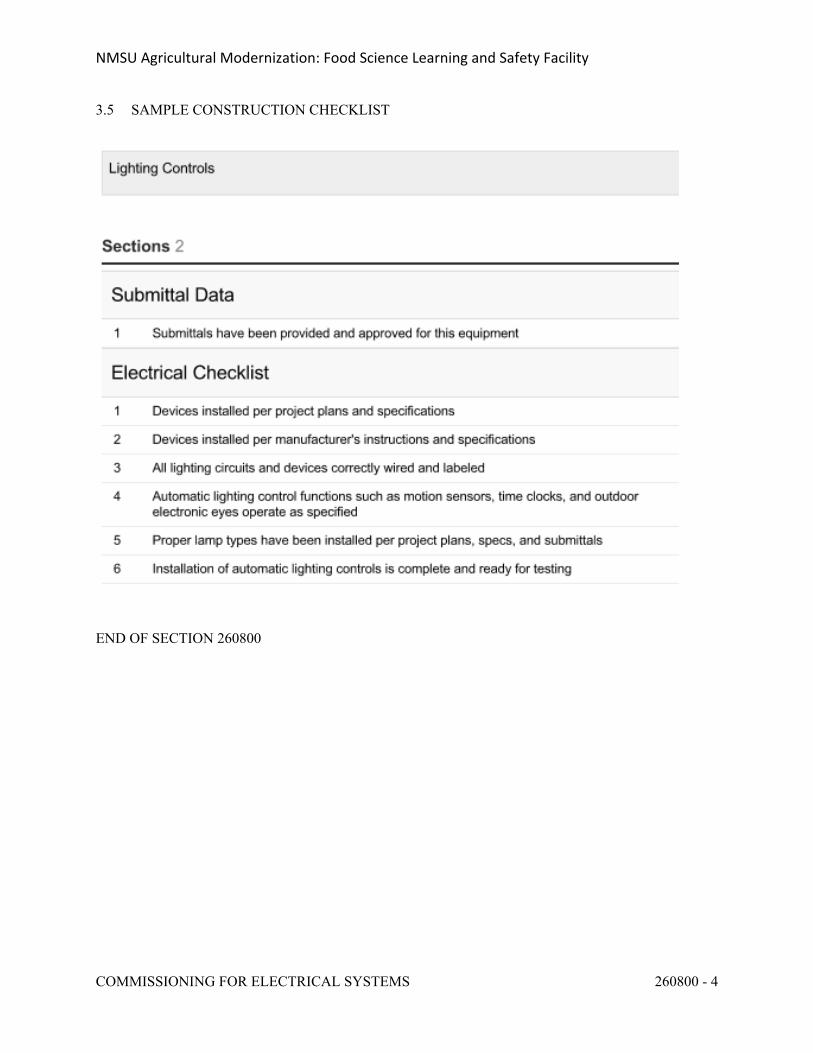
NMSU Agricultural Modernization: Food Science Learning and Safety Facility
COMMISSIONING FOR ELECTRICAL SYSTEMS 260800 - 4
3.5 SAMPLE CONSTRUCTION CHECKLIST
END OF SECTION 260800
NMSU Agricultural Modernization: Food Science Learning and Safety Facility
LIGHTING CONTROL DEVICES 260923 - 1
SECTION 260923 - LIGHTING CONTROL DEVICES
PART 1 - GENERAL
1.1 RELATED DOCUMENTS
A. Drawings and general provisions of the Contract, including General and Supplementary Conditions and Division 01 Specification Sections, apply to this Section.
1.2 SUMMARY
A. Section Includes:
1. Time switches.2. Photoelectric switches.3. Standalone daylight-harvesting switching controls.4. Indoor occupancy sensors.5. Outdoor motion sensors.6. Lighting contactors.7. Emergency shunt relays.
B. Related Requirements:
1. Section 26 2726 "Wiring Devices" for wall-box dimmers, wall-switch occupancy sensors, and manual light switches.
1.3 ACTION SUBMITTALS
A. Product Data: For each type of product.
B. Shop Drawings: Show installation details for occupancy and light-level sensors.
1. Interconnection diagrams showing field-installed wiring.2. Include diagrams for power, signal, and control wiring.
1.4 INFORMATIONAL SUBMITTALS
A. Field quality-control reports.
1.5 CLOSEOUT SUBMITTALS
A. Operation and Maintenance Data: For each type of lighting control device to include in emergency, operation, and maintenance manuals.
NMSU Agricultural Modernization: Food Science Learning and Safety Facility
LIGHTING CONTROL DEVICES 260923 - 2
PART 2 - PRODUCTS
2.1 TIME SWITCHES
A. Manufacturers: Subject to compliance with requirements, provide products by one of, but are not limited to, the following]:
1. Cooper Industries, Inc.2. Intermatic, Inc.3. Invensys Controls.4. Leviton Mfg. Company Inc.5. NSi Industries LLC; TORK Products.6. Tyco Electronics; ALR Brand.
2.2 HIGH-BAY OCCUPANCY SENSORS
A. Manufacturers: Subject to compliance with requirements, provide products by one of the, but are not limited to, the following:
1. WattStopper.
B. General Description: Solid-state unit. The unit is designed to operate with the lamp and ballasts indicated.
1. Listed and labeled as defined in NFPA 70, by a qualified testing agency, and marked for intended location and application.
2. Operation: Turn lights on when coverage area is occupied, and to half-power when unoccupied; with a time delay for turning lights to half-power that is adjustable over a minimum range of 1 to 16 minutes.
3. Continuous Lamp Monitoring: When lamps are dimmed continuously for 24 hours, automatically turn lamps on to full power for 15 minutes for every 24 hours of continuous dimming.
4. Operating Ambient Conditions: 32 to 149 deg F (0 to 65 deg C).5. Mounting: Threaded pipe.6. Time-Delay and Sensitivity Adjustments: Recessed and concealed behind hinged door.7. Detector Technology: PIR.8. Power and dimming control from the lighting fixture ballast that has been modified to
include the dimming capacitor and MyzerPORT option.
C. Detector Coverage: User selectable by interchangeable PIR lenses, suitable for mounting heights from 12 to 50 feet (3.7 to 15.2 m).
D. Accessories: Obtain manufacturer's installation and maintenance kit with laser alignment tool for sensor positioning and power port connectors.
NMSU Agricultural Modernization: Food Science Learning and Safety Facility
LIGHTING CONTROL DEVICES 260923 - 3
2.3 LIGHTING CONTACTORS
A. Manufacturers: Subject to compliance with requirements, provide products by one of the, but are not limited to, the following:
1. Allen-Bradley/Rockwell Automation.2. ASCO Power Technologies, LP; a division of Emerson Electric Co.3. Eaton Corporation.4. General Electric Company; GE Consumer & Industrial - Electrical Distribution; Total
Lighting Control.5. Square D; a brand of Schneider Electric.
B. Description: Electrically operated and electrically held, combination-type lighting contactors with fusible switch, complying with NEMA ICS 2 and UL 508.
1. Current Rating for Switching: Listing or rating consistent with type of load served, including tungsten filament, inductive, and high-inrush ballast (ballast with 15 percent or less total harmonic distortion of normal load current).
2. Fault Current Withstand Rating: Equal to or exceeding the available fault current at the point of installation.
3. Enclosure: Comply with NEMA 250.4. Provide with control and pilot devices as indicated on Drawings, matching the NEMA
type specified for the enclosure.
C. BAS Interface: Provide hardware interface to enable the BAS to monitor and control lighting contactors.
1. Monitoring: On-off status, 2. Control: On-off operation.
2.4 CONDUCTORS AND CABLES
A. Power Wiring to Supply Side of Remote-Control Power Sources: Not smaller than No. 12 AWG. Comply with requirements in Section 26 05 19 "Low-Voltage Electrical Power Conductors and Cables."
B. Classes 2 and 3 Control Cable: Multiconductor cable with stranded-copper conductors not smaller than No. 18AWG. Comply with requirements in Section 26 0519 "Low-Voltage Electrical Power Conductors and Cables."
C. Class 1 Control Cable: Multiconductor cable with stranded-copper conductors not smaller than No. 14 AWG. Comply with requirements in Section 26 0519 "Low-Voltage Electrical Power Conductors and Cables."
NMSU Agricultural Modernization: Food Science Learning and Safety Facility
LIGHTING CONTROL DEVICES 260923 - 4
PART 3 - EXECUTION
3.1 CONTACTOR INSTALLATION
A. Mount electrically held lighting contactors with elastomeric isolator pads to eliminate structure-borne vibration, unless contactors are installed in an enclosure with factory-installed vibration isolators.
3.2 WIRING INSTALLATION
A. Wiring Method: Comply with Section 26 0519 "Low-Voltage Electrical Power Conductors and Cables." Minimum conduit size is 1/2 inch (13 mm).
B. Wiring within Enclosures: Comply with NECA 1. Separate power-limited and nonpower-limited conductors according to conductor manufacturer's written instructions.
C. Size conductors according to lighting control device manufacturer's written instructions unless otherwise indicated.
D. Splices, Taps, and Terminations: Make connections only on numbered terminal strips in junction, pull, and outlet boxes; terminal cabinets; and equipment enclosures.
3.3 IDENTIFICATION
A. Identify components and power and control wiring according to Section 26 0553 "Identification for Electrical Systems."
1. Identify controlled circuits in lighting contactors.2. Identify circuits or luminaires controlled by photoelectric and occupancy sensors at each
sensor.
B. Label time switches and contactors with a unique designation.
3.4 FIELD QUALITY CONTROL
A. Testing Agency: Engage a qualified testing agency to evaluate lighting control devices and perform tests and inspections.
B. Manufacturer's Field Service: Engage a factory-authorized service representative to test and inspect components, assemblies, and equipment installations, including connections.
C. Perform the following tests and inspections with the assistance of a factory-authorized service representative:
1. Operational Test: After installing time switches and sensors, and after electrical circuitry has been energized, start units to confirm proper unit operation.
NMSU Agricultural Modernization: Food Science Learning and Safety Facility
LIGHTING CONTROL DEVICES 260923 - 5
2. Test and adjust controls and safeties. Replace damaged and malfunctioning controls and equipment.
D. Lighting control devices will be considered defective if they do not pass tests and inspections.
E. Prepare test and inspection reports.
3.5 DEMONSTRATION
A. Coordinate demonstration of products specified in this Section with demonstration requirements for low-voltage, programmable lighting control systems specified in Section 26 0943.13 "Addressable-Fixture Lighting Controls" and Section 26 0943.23 "Relay-Based Lighting Controls."
B. Engage a factory-authorized service representative to train Owner's maintenance personnel to adjust, operate, and maintain lighting control devices.
END OF SECTION 260923
NMSU Agricultural Modernization: Food Science Learning and Safety Facility
LOW VOLTAGE DISTRIBUTION TRANSFORMERS 262200 - 1
SECTION 262200 - LOW-VOLTAGE TRANSFORMERS
PART 1 - GENERAL
1.1 RELATED DOCUMENTS
A. Drawings and general provisions of the Contract, including General and Supplementary Conditions and Division 01 Specification Sections, apply to this Section.
1.2 SUMMARY
A. This Section includes the following types of dry-type transformers rated 600 V and less, with capacities up to 1000 kVA:
1. Distribution transformers.2. Buck-boost transformers.
1.3 ACTION SUBMITTALS
A. Product Data: Include rated nameplate data, capacities, weights, dimensions, minimum clearances, installed devices and features, and performance for each type and size of transformer indicated.
B. Shop Drawings: Detail equipment assemblies and indicate dimensions, weights, loads, required clearances, method of field assembly, components, and location and size of each field connection.
1. Wiring Diagrams: Power, signal, and control wiring.
1.4 INFORMATIONAL SUBMITTALS
A. Manufacturer Seismic Qualification Certification: Submit certification that transformers, accessories, and components will withstand seismic forces defined in Section 26 05 48 "Vibration and Seismic Controls for Electrical Systems." Include the following:
1. Basis for Certification: Indicate whether withstand certification is based on actual test of assembled components or on calculation.
a. The term "withstand" means "the unit will remain in place without separation of any parts from the device when subjected to the seismic forces specified."
b. The term "withstand" means "the unit will remain in place without separation of any parts from the device when subjected to the seismic forces specified and the unit will be fully operational after the seismic event."
NMSU Agricultural Modernization: Food Science Learning and Safety Facility
LOW VOLTAGE DISTRIBUTION TRANSFORMERS 262200 - 2
2. Dimensioned Outline Drawings of Equipment Unit: Identify center of gravity and locate and describe mounting and anchorage provisions.
3. Detailed description of equipment anchorage devices on which the certification is based and their installation requirements.
B. Qualification Data: For testing agency.
C. Source quality-control test reports.
D. Field quality-control test reports.
1.5 CLOSEOUT SUBMITTALS
A. Operation and Maintenance Data: For transformers to include in emergency, operation, and maintenance manuals.
1.6 QUALITY ASSURANCE
A. Testing Agency Qualifications: An independent agency, with the experience and capability to conduct the testing indicated, that is a member company of the InterNational Electrical Testing Association or is a nationally recognized testing laboratory (NRTL) as defined by OSHA in 29 CFR 1910.7, and that is acceptable to authorities having jurisdiction.
1. Testing Agency's Field Supervisor: Person currently certified by the InterNational Electrical Testing Association or the National Institute for Certification in Engineering Technologies to supervise on-site testing specified in Part 3.
B. Testing Agency Qualifications: An independent agency, with the experience and capability to conduct the testing indicated, that is a nationally recognized testing laboratory (NRTL) as defined by OSHA in 29 CFR 1910.7.
C. Source Limitations: Obtain each transformer type through one source from a single manufacturer.
D. Electrical Components, Devices, and Accessories: Listed and labeled as defined in NFPA 70, Article 100, by a testing agency acceptable to authorities having jurisdiction, and marked for intended use.
E. Comply with IEEE C57.12.91, "Test Code for Dry-Type Distribution and Power Transformers."
1.7 DELIVERY, STORAGE, AND HANDLING
A. Temporary Heating: Apply temporary heat according to manufacturer's written instructions within the enclosure of each ventilated-type unit, throughout periods during which equipment is not energized and when transformer is not in a space that is continuously under normal control of temperature and humidity.
NMSU Agricultural Modernization: Food Science Learning and Safety Facility
LOW VOLTAGE DISTRIBUTION TRANSFORMERS 262200 - 3
1.8 COORDINATION
A. Coordinate size and location of concrete bases with actual transformer provided. Cast anchor-bolt inserts into bases. Concrete, reinforcement, and formwork requirements are specified with concrete.
B. Coordinate installation of wall-mounting and structure-hanging supports with actual transformer provided.
PART 2 - PRODUCTS
2.1 MANUFACTURERS
A. Available Manufacturers: Subject to compliance with requirements, manufacturers offering products that may be incorporated into the Work include, but are not limited to, the following:
B. Manufacturers: Subject to compliance with requirements, provide products by one of the following:
1. ACME Electric Corporation; Power Distribution Products Division.2. Controlled Power Company.3. Eaton Electrical Inc.; Cutler-Hammer Products.4. Hammond Co.; Matra Electric, Inc.5. Magnetek Power Electronics Group.6. Micron Industries Corp.7. Myers Power Products, Inc.8. Siemens Energy & Automation, Inc.9. Sola/Hevi-Duty.10. Square D; Schneider Electric.
2.2 GENERAL TRANSFORMER REQUIREMENTS
A. Description: Factory-assembled and -tested, air-cooled units for 60-Hz service.
B. Cores: Grain-oriented, non-aging silicon steel.
C. Coils: Continuous windings without splices except for taps.1. Internal Coil Connections: Brazed or pressure type.2. Coil Material: Copper.
2.3 DISTRIBUTION TRANSFORMERS
A. Comply with NEMA ST 20, and list and label as complying with UL 1561.
B. Provide transformers that are constructed to withstand seismic forces specified in Section 26 05 48 "Vibration and Seismic Controls for Electrical Systems."
NMSU Agricultural Modernization: Food Science Learning and Safety Facility
LOW VOLTAGE DISTRIBUTION TRANSFORMERS 262200 - 4
C. Cores: One leg per phase.If all transformers have same enclosure, retain one of two paragraphs and associated subparagraphs below. Retain first paragraph for indoor transformers; second, for outdoor transformers. If several types of enclosures are required for Project, delete paragraphs and indicate enclosure type on Drawings.
D. Enclosure: Ventilated, NEMA 250, Type 2.
1. Core and coil shall be encapsulated within resin compound, sealing out moisture and air.
E. Enclosure: Ventilated, NEMA 250, Type 3R.
1. Core and coil shall be encapsulated within resin compound, sealing out moisture and air.
F. Transformer Enclosure Finish: Comply with NEMA 250.
1. Interior Transformer Finish Color: Gray2. Exterior Transformer Finish Color: Desert Tan
G. Taps for Transformers 25 kVA and Larger: Two 2.5 percent taps above and two 2.5 percent taps below normal full capacity.
H. Insulation Class: 220 deg C, UL-component-recognized insulation system with a maximum of 115 deg C rise above 40 deg C ambient temperature.
I. Energy Efficiency for Transformers Rated 15 kVA and Larger:
1. Complying with NEMA TP 1, Class 1 efficiency levels.2. Tested according to NEMA TP 2.
J. K-Factor Rating: Transformers indicated to be K-factor rated shall comply with UL 1561 requirements for nonsinusoidal load current-handling capability to the degree defined by designated K-factor.
1. Unit shall not overheat when carrying full-load current with harmonic distortion corresponding to designated K-factor.
2. Indicate value of K-factor on transformer nameplate.
K. Electrostatic Shielding: Each winding shall have an independent, single, full-width copper electrostatic shield arranged to minimize interwinding capacitance.
1. Arrange coil leads and terminal strips to minimize capacitive coupling between input and output terminals.
2. Include special terminal for grounding the shield.3. Shield Effectiveness:
a. Capacitance between Primary and Secondary Windings: Not to exceed 33 picofarads over a frequency range of 20 Hz to 1 MHz.
b. Common-Mode Noise Attenuation: Minimum of minus 120 dBA at 0.5 to 1.5 kHz; minimum of minus 65 dBA at 1.5 to 100 kHz.
c. Normal-Mode Noise Attenuation: Minimum of minus 52 dBA at 1.5 to 10 kHz.
NMSU Agricultural Modernization: Food Science Learning and Safety Facility
LOW VOLTAGE DISTRIBUTION TRANSFORMERS 262200 - 5
L. Wall Brackets: Manufacturer's standard brackets.
M. Fungus Proofing: Permanent fungicidal treatment for coil and core.
N. Low-Sound-Level Requirements: Minimum of 3 dBA less than NEMA ST 20 standard sound levels when factory tested according to IEEE C57.12.91.
O. Low-Sound-Level Requirements: Maximum sound levels, when factory tested according to IEEE C57.12.91, as follows:
1. 30 to 50 kVA: 2. 51 to 150 kVA: 3. 151 to 300 kVA: 4. 301 to 500 kVA: 5. 501 to 750 kVA:
2.4 IDENTIFICATION DEVICES
A. Nameplates: Engraved, laminated-plastic or metal nameplate for each distribution transformer, mounted with corrosion-resistant screws. Nameplates and label products are specified in Section 26 05 53 "Identification for Electrical Systems."
2.5 SOURCE QUALITY CONTROL
A. Test and inspect transformers according to IEEE C57.12.91.
B. Factory Sound-Level Tests: Conduct sound-level tests on equipment for this Project.
PART 3 - EXECUTION
3.1 EXAMINATION
A. Examine conditions for compliance with enclosure- and ambient-temperature requirements for each transformer.
B. Verify that field measurements are as needed to maintain working clearances required by NFPA 70 and manufacturer's written instructions.
C. Examine walls, floors, roofs, and concrete bases for suitable mounting conditions where transformers will be installed.
D. Verify that ground connections are in place and requirements in Section 26 0526 "Grounding and Bonding for Electrical Systems" have been met. Maximum ground resistance shall be 5 ohms at location of transformer.
E. Proceed with installation only after unsatisfactory conditions have been corrected.
NMSU Agricultural Modernization: Food Science Learning and Safety Facility
LOW VOLTAGE DISTRIBUTION TRANSFORMERS 262200 - 6
3.2 INSTALLATION
A. Install wall-mounting transformers level and plumb with wall brackets fabricated by transformer manufacturer.
1. Brace wall-mounting transformers as specified in Section 26 05 48 "Vibration and Seismic Controls for Electrical Systems."
B. Construct concrete bases and anchor floor-mounting transformers according to manufacturer's written instructions, seismic codes applicable to Project, and requirements in Section 26 05 29 "Hangers and Supports for Electrical Systems."
C. Sound Isolation: Final conduit connection to transformer to be made with flexible conduit. Isolation pads to be installed on floor mounted transformers, spring hangers for transformers supported by structure.
3.3 CONNECTIONS
A. Ground equipment according to Section 26 0526 "Grounding and Bonding for Electrical Systems."
B. Connect wiring according to Section 26 0519 "Low-Voltage Electrical Power Conductors and Cables."
3.4 FIELD QUALITY CONTROL
A. Testing Agency: Engage a qualified testing agency to perform tests and inspections and prepare test reports.
B. Manufacturer's Field Service: Engage a factory-authorized service representative to inspect, test, and adjust components, assemblies, and equipment installations, including connections. Report results in writing.
C. Perform tests and inspections and prepare test reports.
1. Manufacturer's Field Service: Engage a factory-authorized service representative to inspect components, assemblies, and equipment installations, including connections, and to assist in testing.
D. Tests and Inspections:
1. Perform each visual and mechanical inspection and electrical test stated in NETA Acceptance Testing Specification. Certify compliance with test parameters.
E. Remove and replace units that do not pass tests or inspections and retest as specified above.
F. Infrared Scanning: Two months after Substantial Completion, perform an infrared scan of transformer connections.
NMSU Agricultural Modernization: Food Science Learning and Safety Facility
LOW VOLTAGE DISTRIBUTION TRANSFORMERS 262200 - 7
1. Use an infrared-scanning device designed to measure temperature or detect significant deviations from normal values. Provide documentation of device calibration.
2. Perform 2 follow-up infrared scans of transformers, one at 4 months and the other at 11 months after Substantial Completion.
3. Prepare a certified report identifying transformer checked and describing results of scanning. Include notation of deficiencies detected, remedial action taken, and scanning observations after remedial action.
G. Test Labeling: On completion of satisfactory testing of each unit, attach a dated and signed "Satisfactory Test" label to tested component.
3.5 ADJUSTING
A. Record transformer secondary voltage at each unit for at least 48 hours of typical occupancy period. Adjust transformer taps to provide optimum voltage conditions at secondary terminals. Optimum is defined as not exceeding nameplate voltage plus 10 percent and not being lower than nameplate voltage minus 3 percent at maximum load conditions. Submit recording and tap settings as test results.
B. Connect buck-boost transformers to provide nameplate voltage of equipment being served, plus or minus 5 percent, at secondary terminals.
C. Output Settings Report: Prepare a written report recording output voltages and tap settings.
3.6 CLEANING
A. Vacuum dirt and debris; do not use compressed air to assist in cleaning.
END OF SECTION 262200
NMSU Agricultural Modernization: Food Science Learning and Safety Facility
SWITCHBOARDS 262413 - 1
SECTION 262413 - SWITCHBOARDS
PART 1 - GENERAL
1.1 RELATED DOCUMENTS
A. Drawings and general provisions of the Contract, including General and Supplementary Conditions and Division 01 Specification Sections, apply to this Section.
1.2 SUMMARY
A. Section Includes:
1. Service and distribution switchboards rated 600 V and less.2. Transient voltage suppression devices.3. Disconnecting and overcurrent protective devices.4. Instrumentation.5. Control power.6. Accessory components and features.7. Identification.8. Mimic bus.
1.3 PERFORMANCE REQUIREMENTS
A. Seismic Performance: Switchboards shall withstand the effects of earthquake motions determined according to SEI/ASCE 7.
1. The term "withstand" means "the unit will remain in place without separation of any parts from the device when subjected to the seismic forces specified and the unit will be fully operational after the seismic event."
1.4 ACTION SUBMITTALS
A. Product Data: For each type of switchboard, overcurrent protective device, transient voltage suppression device, ground-fault protector, accessory, and component indicated. Include dimensions and manufacturers' technical data on features, performance, electrical characteristics, ratings, accessories, and finishes.
B. Shop Drawings: For each switchboard and related equipment.
1. Include dimensioned plans, elevations, sections, and details, including required clearances and service space around equipment. Show tabulations of installed devices, equipment features, and ratings.
2. Detail enclosure types for types other than NEMA 250, Type 1.3. Detail bus configuration, current, and voltage ratings.
NMSU Agricultural Modernization: Food Science Learning and Safety Facility
SWITCHBOARDS 262413 - 2
4. Detail short-circuit current rating of switchboards and overcurrent protective devices.5. Include descriptive documentation of optional barriers specified for electrical insulation
and isolation.6. Detail utility company's metering provisions with indication of approval by utility
company.7. Include evidence of NRTL listing for series rating of installed devices.8. Detail features, characteristics, ratings, and factory settings of individual overcurrent
protective devices and auxiliary components.9. Include time-current coordination curves for each type and rating of overcurrent
protective device included in switchboards. Submit on translucent log-log graft paper; include selectable ranges for each type of overcurrent protective device.
10. Include diagram and details of proposed mimic bus.11. Include schematic and wiring diagrams for power, signal, and control wiring.
C. Samples: Representative portion of mimic bus with specified material and finish, for color selection.
1.5 INFORMATIONAL SUBMITTALS
A. Qualification Data: For qualified Installer.
B. Seismic Qualification Certificates: Submit certification that switchboards, overcurrent protective devices, accessories, and components will withstand seismic forces defined in Section 26 0548 "Vibration and Seismic Controls for Electrical Systems." Include the following:
1. Basis for Certification: Indicate whether withstand certification is based on actual test of assembled components or on calculation.
2. Dimensioned Outline Drawings of Equipment Unit: Identify center of gravity and locate and describe mounting and anchorage provisions.
3. Detailed description of equipment anchorage devices on which the certification is based and their installation requirements.
C. Field Quality-Control Reports:
1. Test procedures used.2. Test results that comply with requirements.3. Results of failed tests and corrective action taken to achieve test results that comply with
requirements.
1.6 CLOSEOUT SUBMITTALS
A. Operation and Maintenance Data: For switchboards and components to include in emergency, operation, and maintenance manuals. In addition to items specified in Section 01 7823 "Operation and Maintenance Data," include the following:
1. Routine maintenance requirements for switchboards and all installed components.
NMSU Agricultural Modernization: Food Science Learning and Safety Facility
SWITCHBOARDS 262413 - 3
2. Manufacturer's written instructions for testing and adjusting overcurrent protective devices.
3. Time-current coordination curves for each type and rating of overcurrent protective device included in switchboards. Submit on translucent log-log graft paper; include selectable ranges for each type of overcurrent protective device.
1.7 MAINTENANCE MATERIAL SUBMITTALS
A. Furnish extra materials that match products installed and that are packaged with protective covering for storage and identified with labels describing contents.
1. Potential Transformer Fuses: Equal to 10 percent of quantity installed for each size and type, but no fewer than two of each size and type.
2. Control-Power Fuses: Equal to 10 percent of quantity installed for each size and type, but no fewer than two of each size and type.
3. Fuses and Fusible Devices for Fused Circuit Breakers: Equal to 10 percent of quantity installed for each size and type, but no fewer than three of each size and type.
4. Fuses for Fused Switches: Equal to 10 percent of quantity installed for each size and type, but no fewer than three of each size and type.
5. Fuses for Fused Power-Circuit Devices: Equal to 10 percent of quantity installed for each size and type, but no fewer than three of each size and type.
6. Indicating Lights: Equal to 10 percent of quantity installed for each size and type, but no fewer than one of each size and type.
1.8 QUALITY ASSURANCE
A. Installer Qualifications: An employer of workers qualified as defined in NEMA PB 2.1 and trained in electrical safety as required by NFPA 70E.
B. Testing Agency Qualifications: Member company of NETA or an NRTL.
1. Testing Agency's Field Supervisor: Currently certified by NETA to supervise on-site testing.
C. Source Limitations: Obtain switchboards, overcurrent protective devices, components, and accessories from single source from single manufacturer.
D. Product Selection for Restricted Space: Drawings indicate maximum dimensions for switchboards including clearances between switchboards and adjacent surfaces and other items. Comply with indicated maximum dimensions.
E. Electrical Components, Devices, and Accessories: Listed and labeled as defined in NFPA 70, by a qualified testing agency, and marked for intended location and application.
F. Comply with NEMA PB 2.
G. Comply with NFPA 70.
H. Comply with UL 891.
NMSU Agricultural Modernization: Food Science Learning and Safety Facility
SWITCHBOARDS 262413 - 4
1.9 DELIVERY, STORAGE, AND HANDLING
A. Deliver switchboards in sections or lengths that can be moved past obstructions in delivery path.
B. Handle and prepare switchboards for installation according to NEMA PB 2.1.
1.10 PROJECT CONDITIONS
A. Installation Pathway: Remove and replace access fencing, doors, lift-out panels, and structures to provide pathway for moving switchboards into place.
B. Environmental Limitations:
1. Do not deliver or install switchboards until spaces are enclosed and weathertight, wet work in spaces is complete and dry, work above switchboards is complete, and temporary HVAC system is operating and maintaining ambient temperature and humidity conditions at occupancy levels during the remainder of the construction period.
2. Rate equipment for continuous operation under the following conditions unless otherwise indicated:
a. Ambient Temperature: Not exceeding 104 deg F (40 deg C).b. Altitude: Not exceeding this projects feet above sea level. Contractor to verify
prior to ordering equipment.
C. Service Conditions: NEMA PB 2, usual service conditions, as follows:
1. Ambient temperatures within limits specified.2. Altitude not exceeding this projects feet above sea level. Contractor to verify prior to
ordering equipment.
D. Interruption of Existing Electric Service: Do not interrupt electric service to facilities occupied by Owner or others unless permitted under the following conditions and then only after arranging to provide temporary electric service according to requirements indicated:
1. Notify Architect, Construction Manager, and Building Manager/Owner no fewer than two weeks in advance of proposed interruption of electric service.
2. Indicate method of providing temporary electric service.3. Do not proceed with interruption of electric service without written permission.4. Comply with NFPA 70E.
1.11 COORDINATION
A. Coordinate layout and installation of switchboards and components with other construction that penetrates walls or is supported by them, including electrical and other types of equipment, raceways, piping, encumbrances to workspace clearance requirements, and adjacent surfaces. Maintain required workspace clearances and required clearances for equipment access doors and panels.
NMSU Agricultural Modernization: Food Science Learning and Safety Facility
SWITCHBOARDS 262413 - 5
B. Coordinate sizes and locations of concrete bases with actual equipment provided. Cast anchor-bolt inserts into bases. Concrete, reinforcement, and formwork requirements are specified with concrete.
1.12 WARRANTY
A. Special Warranty: Manufacturer's standard form in which manufacturer agrees to repair or replace transient voltage suppression devices that fail in materials or workmanship within specified warranty period.
1. Warranty Period: Five years from date of Substantial Completion.
PART 2 - PRODUCTS
2.1 MANUFACTURED UNITS
A. Manufacturers: Subject to compliance with requirements, provide products by one of, but are not limited to, the following:
1. Eaton Electrical Inc.; Cutler-Hammer Business Unit.2. Siemens Energy & Automation, Inc.3. Square D; a brand of Schneider Electric.
B. Front-Connected, Front-Accessible Switchboards:
1. Main Devices Fixed, individually mounted.2. Branch Devices: Panel mounted.3. Sections front and rear aligned.
C. Nominal System Voltage: 480Y/277V and 208Y/120V.
D. Main-Bus Continuous: as indicated on the one-line diagram.
E. Seismic Requirements: Fabricate and test switchboards according to IEEE 344 to withstand seismic forces defined in Division 1 for this project.
F. Indoor Enclosures: Steel, NEMA 250, Type 1.
G. Enclosure Finish for Indoor Units: Factory-applied finish in manufacturer's standard gray finish over a rust-inhibiting primer on treated metal surface.
H. Enclosure Finish for Outdoor Units: Factory-applied finish in manufacturer’s Desert Tan finish over a rust-inhibiting primer on treated metal surface.
I. Barriers: Between adjacent switchboard sections.
NMSU Agricultural Modernization: Food Science Learning and Safety Facility
SWITCHBOARDS 262413 - 6
J. Insulation and isolation for main bus of main section and main and vertical buses of feeder sections.
K. Customer Metering Compartment: A separate customer metering compartment and section with front hinged door, for indicated metering, and current transformers for each meter. Current transformer secondary wiring shall be terminated on shorting-type terminal blocks.
L. Bus Transition and Incoming Pull Sections: Matched and aligned with basic switchboard.
M. Hinged Front Panels: Allow access to circuit breaker, metering, accessory, and blank compartments.
N. Pull Box on Top of Switchboard:
1. Adequate ventilation to maintain temperature in pull box within same limits as switchboard.
2. Set back from front to clear circuit-breaker removal mechanism.3. Removable covers shall form top, front, and sides. Top covers at rear shall be easily
removable for drilling and cutting.4. Bottom shall be insulating, fire-resistive material with separate holes for cable drops into
switchboard.5. Cable supports shall be arranged to facilitate cabling and adequate to support cables
indicated, including those for future installation.
O. Buses and Connections: Three phase, four wire unless otherwise indicated.
1. Phase- and Neutral-Bus Material: Hard-drawn copper of 98 percent conductivity, with copper feeder circuit-breaker line connections.
2. Load Terminals: Insulated, rigidly braced, runback bus extensions, of same material as through buses, equipped with compression connectors for outgoing circuit conductors. Provide load terminals for future circuit-breaker positions at full-ampere rating of circuit-breaker position.
3. Ground Bus: Minimum-size required by UL 891, hard-drawn copper of 98 percent conductivity, equipped with compression connectors for feeder and branch-circuit ground conductors.
4. Main Phase Buses and Equipment Ground Buses: Uniform capacity for entire length of switchboard's main and distribution sections. Provide for future extensions from both ends.
5. Neutral Buses: 100 percent of the ampacity of phase buses unless otherwise indicated, equipped with compression connectors for outgoing circuit neutral cables.
6. Isolation Barrier Access Provisions: Permit checking of bus-bolt tightness.
P. Future Devices: Equip compartments with mounting brackets, supports, bus connections, and appurtenances at full rating of circuit-breaker compartment.
Q. Bus-Bar Insulation: Factory-applied, flame-retardant, tape wrapping of individual bus bars or flame-retardant, spray-applied insulation. Minimum insulation temperature rating of 105 deg C.
R. Fungus Proofing: Permanent fungicidal treatment for overcurrent protective devices and other components including instruments and instrument transformers.
NMSU Agricultural Modernization: Food Science Learning and Safety Facility
SWITCHBOARDS 262413 - 7
2.2 TRANSIENT VOLTAGE SUPPRESSION DEVICES
A. Manufacturers: Subject to compliance with requirements, provide products by one of, but are not limited to, the following:
1. Eaton Electrical Inc.; Cutler-Hammer Business Unit.2. Siemens Energy & Automation, Inc.3. Square D; a brand of Schneider Electric.
B. Selection of options in first paragraph below is a matter of ease of maintenance and replacement; coordinate final choices with Owner's maintenance personnel. Wired-in type offers more safety with a slight reduction in protection; modular types offer the quickest maintenance, but may come at a slightly higher cost. See the Evaluations in Section 264313 "Surge Protection for Low-Voltage Electrical Power Circuits" for guidance on revising this article.
C. Surge Protection Device Description: IEEE C62.41-compliant, integrally mounted, plug-in, solid-state, parallel-connected, modular (with field-replaceable modules) type, with sine-wave tracking suppression and filtering modules, UL 1449, second edition, short-circuit current rating matching or exceeding the switchboard short-circuit rating, and with the following features and accessories:
1. Fuses, rated at 200-kA interrupting capacity.2. Fabrication using bolted compression lugs for internal wiring.3. Integral disconnect switch.4. Redundant suppression circuits.5. Redundant replaceable modules.6. Arrangement with wire connections to phase buses, neutral bus, and ground bus.7. LED indicator lights for power and protection status.8. Audible alarm, with silencing switch, to indicate when protection has failed.9. Form-C contacts rated at 5 A and 250-V ac, one normally open and one normally closed,
for remote monitoring of system operation. Contacts shall reverse position on failure of any surge diversion module or on opening of any current-limiting device. Coordinate with building power monitoring and control system.
10. Six-digit, transient-event counter set to totalize transient surges.
D. Peak Single-Impulse Surge Current Rating: 160 kA per mode/320 kA per phase.
E. Withstand Capabilities: 12,000 IEEE C62.41, Category C3 (10 kA), 8-by-20-mic.sec. surges with less than 5 percent change in clamping voltage.
F. Protection modes and UL 1449 SVR for grounded wye circuits with 480Y/277V, three-phase, four-wire circuits shall be as follows:
1. Line to Neutral: 800 V for 480Y/277.2. Line to Ground: 800 V for 480Y/277.3. Neutral to Ground: 800 V for 480Y/277.
NMSU Agricultural Modernization: Food Science Learning and Safety Facility
SWITCHBOARDS 262413 - 8
G. Protection modes and UL 1449 SVR for 240/120-V, three-phase, four-wire circuits with high leg shall be as follows:
1. Line to Neutral: 400 V, 800 V from high leg.2. Line to Ground: 400 V.3. Neutral to Ground: 400 V.
H. Protection modes and UL 1449 SVR for 240-, 480-, or 600-V, three-phase, three-wire, delta circuits shall be as follows:
1. Line to Line: 2500 V for 600 V.2. Line to Ground: 2500 V for 600 V.
2.3 DISCONNECTING AND OVERCURRENT PROTECTIVE DEVICES
A. Molded-Case Circuit Breaker (MCCB): Comply with UL 489, with interrupting capacity to meet available fault currents.
1. Thermal-Magnetic Circuit Breakers: Inverse time-current element for low-level overloads, and instantaneous magnetic trip element for short circuits. Adjustable magnetic trip setting for circuit-breaker frame sizes 250 A and larger.
2. Adjustable Instantaneous-Trip Circuit Breakers: Magnetic trip element with front-mounted, field-adjustable trip setting.
3. Electronic trip circuit breakers with rms sensing; field-replaceable rating plug or field-replicable electronic trip; and the following field-adjustable settings:
a. Instantaneous trip.b. Long- and short-time pickup levels.c. Long- and short-time time adjustments.d. Ground-fault pickup level, time delay, and I2t response.
4. Current-Limiting Circuit Breakers: Frame sizes 400 A and smaller; let-through ratings less than NEMA FU 1, RK-5.
5. Integrally Fused Circuit Breakers: Thermal-magnetic trip element with integral limiter-style fuse listed for use with circuit breaker; trip activation on fuse opening or on opening of fuse compartment door.
6. GFCI Circuit Breakers: Single- and two-pole configurations with Class A ground-fault protection (6-mA trip).
7. Ground-Fault Equipment Protection (GFEP) Circuit Breakers: Class B ground-fault protection (30-mA trip).
8. Molded-Case Circuit-Breaker (MCCB) Features and Accessories:
a. Standard frame sizes, trip ratings, and number of poles.b. Lugs: Compression style, suitable for number, size, trip ratings, and conductor
material.c. Application Listing: Appropriate for application; Type SWD for switching
fluorescent lighting loads; Type HID for feeding fluorescent and high-intensity discharge (HID) lighting circuits.
NMSU Agricultural Modernization: Food Science Learning and Safety Facility
SWITCHBOARDS 262413 - 9
d. Ground-Fault Protection: Integrally mounted relay and trip unit with adjustable pickup and time-delay settings, push-to-test feature, and ground-fault indicator.
e. Zone-Selective Interlocking: Integral with electronic trip unit; for interlocking ground-fault protection function.
f. Communication Capability: Universal-mounted communication module with functions and features compatible with power monitoring and control system specified in Section 260913 "Electrical Power Monitoring and Control."
g. Shunt Trip: 120-V trip coil energized from separate circuit, set to trip at 75 percent of rated voltage.
h. Undervoltage Trip: Set to operate at 35 to 75 percent of rated voltage without intentional time delay.
i. Auxiliary Contacts: Two SPDT switches with "a" and "b" contacts; "a" contacts mimic circuit-breaker contacts, "b" contacts operate in reverse of circuit-breaker contacts.
j. Key Interlock Kit: Externally mounted to prohibit circuit-breaker operation; key shall be removable only when circuit breaker is in off position.See Editing Instruction No. 1 in the Evaluations for cautions about naming manufacturers. Retain first subparagraph and list of manufacturers below. See Section 016000 "Product Requirements."
9. Manufacturers: Subject to compliance with requirements, provide products by one, but are not limited to, the following]:
a. Boltswitch, Inc.b. Eaton Electrical Inc.; Cutler-Hammer Business Unit.c. Pringle Electrical Manufacturing Company, Inc.d. Siemens Energy & Automation, Inc.e. Square D; a brand of Schneider Electric.
10. Main-Contact Interrupting Capability: Minimum of 12 times the switch current rating.11. Operating Mechanism: Manual handle operation to close switch; stores energy in
mechanism for opening and closing.
a. Electrical Trip: Operation of lever or push-button trip switch, or trip signal from ground-fault relay or remote-control device, causes switch to open.
b. Mechanical Trip: Operation of mechanical lever, push button, or other device causes switch to open.
12. Auxiliary Switches: Factory installed, single pole, double throw, with leads connected to terminal block, and including one set more than quantity required for functional performance indicated.
13. Service-Rated Switches: Labeled for use as service equipment.14. Ground-Fault Relay: Comply with UL 1053; self-powered type with mechanical ground-
fault indicator, test function, tripping relay with internal memory, and three-phase current transformer/sensor.
a. Configuration: Integrally mounted relay and trip unit with adjustable pickup and time-delay settings, push-to-test feature, and ground-fault indicator.
b. Internal Memory: Integrates the cumulative value of intermittent arcing ground-fault currents and uses the effect to initiate tripping.
c. No-Trip Relay Test: Permits ground-fault simulation test without tripping switch.
NMSU Agricultural Modernization: Food Science Learning and Safety Facility
SWITCHBOARDS 262413 - 10
d. Test Control: Simulates ground fault to test relay and switch (or relay only if "no-trip" mode is selected).
15. Open-Fuse Trip Device: Arranged to trip switch open if a phase fuse opens.
2.4 INSTRUMENTATION
A. Instrument Transformers: IEEE C57.13, NEMA EI 21.1, and the following:
1. Potential Transformers: IEEE C57.13; 120 V, 60 Hz, single secondary; disconnecting type with integral fuse mountings. Burden and accuracy shall be consistent with connected metering and relay devices.
2. Current Transformers: IEEE C57.13; 5 A, 60 Hz, secondary; bar or window type; single secondary winding and secondary shorting device. Burden and accuracy shall be consistent with connected metering and relay devices.
3. Control-Power Transformers: Dry type, mounted in separate compartments for units larger than 3 kVA.
4. Current Transformers for Neutral and Ground-Fault Current Sensing: Connect secondary wiring to ground overcurrent relays, via shorting terminals, to provide selective tripping of main and tie circuit breaker. Coordinate with feeder circuit-breaker, ground-fault protection.
B. Multifunction Digital-Metering Monitor: Microprocessor-based unit suitable for three- or four-wire systems and with the following features:
1. Switch-selectable digital display of the following values with maximum accuracy tolerances as indicated:
a. Phase Currents, Each Phase: Plus or minus 1 percent.b. Phase-to-Phase Voltages, Three Phase: Plus or minus 1 percent.c. Phase-to-Neutral Voltages, Three Phase: Plus or minus 1 percent.d. Megawatts: Plus or minus 2 percent.e. Megavars: Plus or minus 2 percent.f. Power Factor: Plus or minus 2 percent.g. Frequency: Plus or minus 0.5 percent.h. Accumulated Energy, Megawatt Hours: Plus or minus 2 percent; accumulated
values unaffected by power outages up to 72 hours.i. Megawatt Demand: Plus or minus 2 percent; demand interval programmable from
five to 60 minutes.j. Contact devices to operate remote impulse-totalizing demand meter.
2. Mounting: Display and control unit flush or semiflush mounted in instrument compartment door.
C. Ammeters, Voltmeters, and Power-Factor Meters: ANSI C39.1.
1. Meters: 4-inch (100-mm) diameter or 6 inches (150 mm) square, flush or semiflush, with antiparallax 250-degree scales and external zero adjustment.
2. Voltmeters: Cover an expanded-scale range of nominal voltage plus 10 percent.
NMSU Agricultural Modernization: Food Science Learning and Safety Facility
SWITCHBOARDS 262413 - 11
D. Watt-Hour Meters and Wattmeters:
1. Comply with ANSI C12.1.2. Three-phase induction type with two stators, each with current and potential coil, rated
5 A, 120 V, 60 Hz.3. Suitable for connection to three- and four-wire circuits.4. Potential indicating lamps.5. Adjustments for light and full load, phase balance, and power factor.6. Four-dial clock register.7. Integral demand indicator.8. Contact devices to operate remote impulse-totalizing demand meter.9. Ratchets to prevent reverse rotation.10. Removable meter with drawout test plug.11. Semiflush mounted case with matching cover.12. Appropriate multiplier tag.
E. Impulse-Totalizing Demand Meter:
1. Comply with ANSI C12.1.2. Suitable for use with switchboard watt-hour meter, including two-circuit totalizing relay.3. Cyclometer.4. Four-dial, totalizing kilowatt-hour register.5. Positive chart drive mechanism.6. Capillary pen holding a minimum of one month's ink supply.7. Roll chart with minimum 31-day capacity; appropriate multiplier tag.8. Capable of indicating and recording 15-minute integrated demand of totalized system.
2.5 CONTROL POWER
A. Control Circuits: 120-V ac, supplied from remote branch circuit.
B. Control Circuits: 24V dc.
C. Control-Power Fuses: Primary and secondary fuses for current-limiting and overload protection of transformer and fuses for protection of control circuits.
D. Control Wiring: Factory installed, with bundling, lacing, and protection included. Provide flexible conductors for No. 8 AWG and smaller, for conductors across hinges, and for conductors for interconnections between shipping units.
2.6 ACCESSORY COMPONENTS AND FEATURES
A. Accessory Set: Include tools and miscellaneous items required for overcurrent protective device test, inspection, maintenance, and operation.
NMSU Agricultural Modernization: Food Science Learning and Safety Facility
SWITCHBOARDS 262413 - 12
2.7 IDENTIFICATION
A. Mimic Bus: Entire single-line switchboard bus work, as depicted on factory record drawing, on a photoengraved nameplate.
1. Nameplate: At least 0.032-inch- (0.813-mm-) thick anodized aluminum, located at eye level on front cover of the switchboard incoming service section.
B. Mimic Bus: Entire single-line switchboard bus work, as depicted on factory record drawing, on an engraved laminated-plastic (Gravoply) nameplate.
1. Nameplate: At least 0.0625-inch- (1.588 mm-) thick laminated plastic (Gravoply), located at eye level on front cover of the switchboard incoming service section.
C. Mimic Bus: Continuously integrated mimic bus factory applied to front of switchboard. Arrange in single-line diagram format, using symbols and letter designations consistent with final mimic-bus diagram.
D. Coordinate mimic-bus segments with devices in switchboard sections to which they are applied. Produce a concise visual presentation of principal switchboard components and connections.
E. Presentation Media: Painted graphics in color contrasting with background color to represent bus and components, complete with lettered designations.
F. Service Equipment Label: NRTL labeled for use as service equipment for switchboards with one or more service disconnecting and overcurrent protective devices.
PART 3 - EXECUTION
3.1 EXAMINATION
A. Receive, inspect, handle, and store switchboards according to NEMA PB 2.1.
B. Examine switchboards before installation. Reject switchboards that are moisture damaged or physically damaged.
C. Examine elements and surfaces to receive switchboards for compliance with installation tolerances and other conditions affecting performance of the Work.
D. Proceed with installation only after unsatisfactory conditions have been corrected.
3.2 INSTALLATION
A. Install switchboards and accessories according to NEMA PB 2.1.
B. Equipment Mounting: Install switchboards on concrete base, 4-inch (100-mm) nominal thickness. Comply with requirements for concrete base specified in [Section 03 3000 "Cast-in-Place Concrete."] [Section 03 3053 "Miscellaneous Cast-in-Place Concrete."]
NMSU Agricultural Modernization: Food Science Learning and Safety Facility
SWITCHBOARDS 262413 - 13
1. Install dowel rods to connect concrete base to concrete floor. Unless otherwise indicated, install dowel rods on 18-inch (450-mm) centers around the full perimeter of concrete base.
2. For supported equipment, install epoxy-coated anchor bolts that extend through concrete base and anchor into structural concrete floor.
3. Place and secure anchorage devices. Use setting drawings, templates, diagrams, instructions, and directions furnished with items to be embedded.
4. Install anchor bolts to elevations required for proper attachment to switchboards.
C. Temporary Lifting Provisions: Remove temporary lifting eyes, channels, and brackets and temporary blocking of moving parts from switchboard units and components.
D. Comply with mounting and anchoring requirements specified in Section 26 0548 "Vibration and Seismic Controls for Electrical Systems."
E. Operating Instructions: Frame and mount the printed basic operating instructions for switchboards, including control and key interlocking sequences and emergency procedures. Fabricate frame of finished wood or metal and cover instructions with clear acrylic plastic. Mount on front of switchboards.
F. Install filler plates in unused spaces of panel-mounted sections.
G. Install overcurrent protective devices, transient voltage suppression devices, and instrumentation.
1. Set field-adjustable switches and circuit-breaker trip ranges.
H. Comply with NECA 1.
3.3 IDENTIFICATION
A. Identify field-installed conductors, interconnecting wiring, and components; provide warning signs complying with requirements for identification specified in Section 26 0553 "Identification for Electrical Systems."
B. Switchboard Nameplates: Label each switchboard compartment with a nameplate complying with requirements for identification specified in Section 26 0553 "Identification for Electrical Systems."
C. Device Nameplates: Label each disconnecting and overcurrent protective device and each meter and control device mounted in compartment doors with a nameplate complying with requirements for identification specified in Section 26 0553 "Identification for Electrical Systems."
NMSU Agricultural Modernization: Food Science Learning and Safety Facility
SWITCHBOARDS 262413 - 14
3.4 FIELD QUALITY CONTROL
A. Testing Agency: Engage a qualified testing agency to perform tests and inspections.
B. Manufacturer's Field Service: Engage a factory-authorized service representative to inspect, test, and adjust components, assemblies, and equipment installations, including connections.
C. Perform tests and inspections.
1. Manufacturer's Field Service: Engage a factory-authorized service representative to inspect components, assemblies, and equipment installations, including connections, and to assist in testing.
D. Acceptance Testing Preparation:
1. Test insulation resistance for each switchboard bus, component, connecting supply, feeder, and control circuit.
2. Test continuity of each circuit.
E. Tests and Inspections:
1. Perform each visual and mechanical inspection and electrical test stated in NETA Acceptance Testing Specification. Certify compliance with test parameters.
2. Correct malfunctioning units on-site, where possible, and retest to demonstrate compliance; otherwise, replace with new units and retest.
3. Perform the following infrared scan tests and inspections and prepare reports:
a. Initial Infrared Scanning: After Substantial Completion, but not more than 60 days after Final Acceptance, perform an infrared scan of each switchboard. Remove front panels so joints and connections are accessible to portable scanner.
b. Follow-up Infrared Scanning: Perform an additional follow-up infrared scan of each switchboard 11 months after date of Substantial Completion.
c. Instruments and Equipment:
1) Use an infrared scanning device designed to measure temperature or to detect significant deviations from normal values. Provide calibration record for device.
4. Test and adjust controls, remote monitoring, and safeties. Replace damaged and malfunctioning controls and equipment.
F. Switchboard will be considered defective if it does not pass tests and inspections.
G. Prepare test and inspection reports, including a certified report that identifies switchboards included and that describes scanning results. Include notation of deficiencies detected, remedial action taken, and observations after remedial action.
NMSU Agricultural Modernization: Food Science Learning and Safety Facility
SWITCHBOARDS 262413 - 15
3.5 ADJUSTING
A. Adjust moving parts and operable components to function smoothly, and lubricate as recommended by manufacturer.
B. Set field-adjustable circuit-breaker trip ranges as specified in Section 26 0573 "Overcurrent Protective Device Coordination Study."
3.6 PROTECTION
A. Temporary Heating: Apply temporary heat, to maintain temperature according to manufacturer's written instructions, until switchboard is ready to be energized and placed into service.
3.7 DEMONSTRATION
A. Engage a factory-authorized service representative to train Owner's maintenance personnel to adjust, operate, and maintain switchboards, overcurrent protective devices, instrumentation, and accessories.
END OF SECTION 262413
NMSU Agricultural Modernization: Food Science Learning and Safety Facility
PANELBOARDS 262416 - 1
SECTION 262416 – PANELBOARDS
PART 1- GENERAL
1.1 RELATED DOCUMENTS
A. Drawings and general provisions of the Contract, including General and Supplementary Conditions and Division 01 Specification Sections, apply to this Section.
1.2 SUMMARY
A. Section Includes:
1. Distribution panelboards.2. Lighting and appliance branch-circuit panelboards.3. Load centers.4. Electronic-grade panelboards.
1.3 DEFINITIONS
A. SVR: Suppressed voltage rating.
B. TVSS: Transient voltage surge suppressor.
1.4 ACTION SUBMITTALS
A. Product Data: For each type of panelboard, switching and overcurrent protective device, transient voltage suppression device, accessory, and component indicated. Include dimensions and manufacturers' technical data on features, performance, electrical characteristics, ratings, and finishes.
B. Shop Drawings: For each panelboard and related equipment.
1. Include dimensioned plans, elevations, sections, and details. Show tabulations of installed devices, equipment features, and ratings.
2. Detail enclosure types and details for types other than NEMA 250, Type 1.3. Detail bus configuration, current, and voltage ratings.4. Short-circuit current rating of panelboards and overcurrent protective devices.5. Include evidence of NRTL listing for series rating of installed devices.6. Detail features, characteristics, ratings, and factory settings of individual overcurrent
protective devices and auxiliary components.7. Include wiring diagrams for power, signal, and control wiring.8. Include time-current coordination curves for each type and rating of overcurrent
protective device included in panelboards. Submit on translucent log-log graft paper; include selectable ranges for each type of overcurrent protective device.
NMSU Agricultural Modernization: Food Science Learning and Safety Facility
PANELBOARDS 262416 - 2
1.5 INFORMATIONAL SUBMITTALS
A. Qualification Data: For qualified testing agency.
B. Seismic Qualification Certificates: Submit certification that panelboards, overcurrent protective devices, accessories, and components will withstand seismic forces defined in Section 26 0548 "Vibration and Seismic Controls for Electrical Systems." Include the following:
1. Basis for Certification: Indicate whether withstand certification is based on actual test of assembled components or on calculation.
2. Dimensioned Outline Drawings of Equipment Unit: Identify center of gravity and locate and describe mounting and anchorage provisions.
3. Detailed description of equipment anchorage devices on which the certification is based and their installation requirements.
C. Field Quality-Control Reports:
1. Test procedures used.2. Test results that comply with requirements.3. Results of failed tests and corrective action taken to achieve test results that comply with
requirements.
D. Panelboard Schedules: For installation in panelboards. Submit final versions after load balancing.
1.6 CLOSEOUT SUBMITTALS
A. Operation and Maintenance Data: For panelboards and components to include in emergency, operation, and maintenance manuals. In addition to items specified in Section 01 7823 "Operation and Maintenance Data," include the following:
1. Manufacturer's written instructions for testing and adjusting overcurrent protective devices.
2. Time-current curves, including selectable ranges for each type of overcurrent protective device that allows adjustments.
1.7 MAINTENANCE MATERIAL SUBMITTALS
A. Furnish extra materials that match products installed and that are packaged with protective covering for storage and identified with labels describing contents.
1. Keys: Two spares for each type of panelboard cabinet lock.2. Circuit Breakers Including GFCI and Ground Fault Equipment Protection (GFEP) Types:
Two spares for each panelboard.3. Fuses for Fused Switches: Equal to 10 percent of quantity installed for each size and
type, but no fewer than three of each size and type.4. Fuses for Fused Power-Circuit Devices: Equal to 10 percent of quantity installed for
each size and type, but no fewer than three of each size and type.
NMSU Agricultural Modernization: Food Science Learning and Safety Facility
PANELBOARDS 262416 - 3
1.8 QUALITY ASSURANCE
A. Testing Agency Qualifications: Member company of NETA or an NRTL.
1. Testing Agency's Field Supervisor: Currently certified by NETA to supervise on-site testing.
B. Source Limitations: Obtain panelboards, overcurrent protective devices, components, and accessories from single source from single manufacturer.
C. Product Selection for Restricted Space: Drawings indicate maximum dimensions for panelboards including clearances between panelboards and adjacent surfaces and other items. Comply with indicated maximum dimensions.
D. Electrical Components, Devices, and Accessories: Listed and labeled as defined in NFPA 70, by a qualified testing agency, and marked for intended location and application.
E. Comply with NEMA PB 1.
F. Comply with NFPA 70.
1.9 DELIVERY, STORAGE, AND HANDLING
A. Remove loose packing and flammable materials from inside panelboards; install temporary electric heating (250 W per panelboard) to prevent condensation.
B. Handle and prepare panelboards for installation according to NEMA PB 1.
1.10 PROJECT CONDITIONS
A. Environmental Limitations:
1. Do not deliver or install panelboards until spaces are enclosed and weathertight, wet work in spaces is complete and dry, work above panelboards is complete, and temporary HVAC system is operating and maintaining ambient temperature and humidity conditions at occupancy levels during the remainder of the construction period.
2. Rate equipment for continuous operation under the following conditions unless otherwise indicated:
a. Ambient Temperature: Not exceeding 23 deg F (minus 5 deg C) to plus 104 deg F (plus 40 deg C).
b. Altitude: Not exceeding project site elevation. Contractor to verify site elevation prior to ordering equipment.
B. Interruption of Existing Electric Service: Do not interrupt electric service to facilities occupied by Owner or others unless permitted under the following conditions and then only after arranging to provide temporary electric service according to requirements indicated:
NMSU Agricultural Modernization: Food Science Learning and Safety Facility
PANELBOARDS 262416 - 4
1. Notify Architect, Construction Manager, and Building Manager/Owner no fewer than two weeks in advance of proposed interruption of electric service.
2. Do not proceed with interruption of electric service without written permission.3. Comply with NFPA 70E.
1.11 COORDINATION
A. Coordinate layout and installation of panelboards and components with other construction that penetrates walls or is supported by them, including electrical and other types of equipment, raceways, piping, encumbrances to workspace clearance requirements, and adjacent surfaces. Maintain required workspace clearances and required clearances for equipment access doors and panels.
B. Coordinate sizes and locations of concrete bases with actual equipment provided. Cast anchor-bolt inserts into bases. Concrete, reinforcement, and formwork requirements are specified with concrete.
1.12 WARRANTY
A. Special Warranty: Manufacturer's standard form in which manufacturer agrees to repair or replace transient voltage suppression devices that fail in materials or workmanship within specified warranty period.
1. Warranty Period: Five years from date of Substantial Completion.
PART 2- PRODUCTS
2.1 GENERAL REQUIREMENTS FOR PANELBOARDS
A. Fabricate and test panelboards according to IEEE 344 to withstand seismic forces defined in Section 26 0548 "Vibration and Seismic Controls for Electrical Systems."
B. Enclosures: Flush and/or surface mounted cabinets as indicated on plans.
1. Rated for environmental conditions at installed location.
a. Indoor Dry and Clean Locations: NEMA 250, Type 1.b. Outdoor Locations: NEMA 250, Type 3R.c. Other Wet or Damp Indoor Locations: NEMA 250, Type 4.
2. Front: Secured to box with concealed trim clamps. For surface-mounted fronts, match box dimensions; for flush-mounted fronts, overlap box.
3. Hinged Front Cover: Entire front trim hinged to box and with standard door within hinged trim cover.
4. Skirt for Surface-Mounted Panelboards: Same gage and finish as panelboard front with flanges for attachment to panelboard, wall, and ceiling or floor.
NMSU Agricultural Modernization: Food Science Learning and Safety Facility
PANELBOARDS 262416 - 5
5. Gutter Extension and Barrier: Same gage and finish as panelboard enclosure; integral with enclosure body. Arrange to isolate individual panel sections.
6. Finishes:
a. Panels and Trim: galvanized steel, factory finished immediately after cleaning and pretreating with manufacturer's standard two-coat, baked-on finish consisting of prime coat and thermosetting topcoat.
1) Exterior panelboards to be factory painted DESERT TAN.
b. Back Boxes: Galvanized steel.c. Fungus Proofing: Permanent fungicidal treatment for overcurrent protective
devices and other components.7. Directory Card: Inside panelboard door, mounted in transparent card holder.
C. Incoming Mains Location: Top and/or bottom depending on installation requirements.
D. Phase, Neutral, and Ground Buses:
1. Material: Hard-drawn copper, 98 percent conductivity.2. Equipment Ground Bus: Adequate for feeder and branch-circuit equipment grounding
conductors; bonded to box.3. Isolated Ground Bus: Adequate for branch-circuit isolated ground conductors; insulated
from box.4. Extra-Capacity Neutral Bus: Neutral bus rated 200 percent of phase bus and UL listed as
suitable for nonlinear loads.5. Split Bus: Vertical buses divided into individual vertical sections.
E. Conductor Connectors: Suitable for use with conductor material and sizes.
1. Material: Hard-drawn copper, 98 percent conductivity.2. Main and Neutral Lugs: Compression type.3. Ground Lugs and Bus-Configured Terminators: Compression type.4. Feed-Through Lugs: Compression type, suitable for use with conductor material. Locate
at opposite end of bus from incoming lugs or main device.5. Subfeed (Double) Lugs: Compression type suitable for use with conductor material.
Locate at same end of bus as incoming lugs or main device.6. Gutter-Tap Lugs: Compression type suitable for use with conductor material. Locate at
same end of bus as incoming lugs or main device.7. Extra-Capacity Neutral Lugs: Rated 200 percent of phase lugs mounted on extra-
capacity neutral bus.
F. Service Equipment Label: NRTL labeled for use as service equipment for panelboards or load centers with one or more main service disconnecting and overcurrent protective devices.
G. Future Devices: Mounting brackets, bus connections, filler plates, and necessary appurtenances required for future installation of devices.
H. Panelboard Short-Circuit Current Rating: Fully rated to interrupt symmetrical short-circuit current available at terminals.
NMSU Agricultural Modernization: Food Science Learning and Safety Facility
PANELBOARDS 262416 - 6
2.2 PERFORMANCE REQUIREMENTS
A. Seismic Performance: Panelboards shall withstand the effects of earthquake motions determined according to SEI/ASCE 7.
1. The term "withstand" means "the unit will remain in place without separation of any parts from the device when subjected to the seismic forces specified and the unit will be fully operational after the seismic event.
B. Surge Suppression: Factory installed as an integral part of indicated panelboards, complying with UL 1449 SPD Type 1.
2.3 DISTRIBUTION PANELBOARDS
A. Manufacturers: Subject to compliance with requirements, provide products by one of, but are not limited to, the following:
1. Eaton Electrical Inc.; Cutler-Hammer Business Unit.2. Siemens Energy & Automation, Inc.3. Square D; a brand of Schneider Electric.
B. Panelboards: NEMA PB 1, power and feeder distribution type.
C. Doors: Secured with vault-type latch with tumbler lock; keyed alike.
1. For doors more than 36 inches (914 mm) high, provide two latches, keyed alike.
D. Mains: Circuit breaker and/or Lugs only.
E. Branch Overcurrent Protective Devices for Circuit-Breaker Frame Sizes 125 A and Smaller: Plug-in circuit breakers.
2.4 LIGHTING AND APPLIANCE BRANCH-CIRCUIT PANELBOARDS
A. Manufacturers: Subject to compliance with requirements, provide products by one of, but are not limited to, the following:
1. Eaton Electrical Inc.; Cutler-Hammer Business Unit.2. Siemens Energy & Automation, Inc.3. Square D; a brand of Schneider Electric.
B. Panelboards: NEMA PB 1, lighting and appliance branch-circuit type.
C. Mains: Circuit breaker or lugs only.
D. Branch Overcurrent Protective Devices: Plug-in circuit breakers, replaceable without disturbing adjacent units.
NMSU Agricultural Modernization: Food Science Learning and Safety Facility
PANELBOARDS 262416 - 7
E. Doors: Concealed hinges; secured with flush latch with tumbler lock; keyed alike.
2.5 DISCONNECTING AND OVERCURRENT PROTECTIVE DEVICES
A. Manufacturers: Subject to compliance with requirements, provide products by one of, but are not limited to, the following:
1. Eaton Electrical Inc.; Cutler-Hammer Business Unit.2. Siemens Energy & Automation, Inc.3. Square D; a brand of Schneider Electric.
B. Molded-Case Circuit Breaker (MCCB): Comply with UL 489, with interrupting capacity to meet available fault currents.
1. Thermal-Magnetic Circuit Breakers: Inverse time-current element for low-level overloads, and instantaneous magnetic trip element for short circuits. Adjustable magnetic trip setting for circuit-breaker frame sizes 250 A and larger.
2. Adjustable Instantaneous-Trip Circuit Breakers: Magnetic trip element with front-mounted, field-adjustable trip setting.
3. Electronic trip circuit breakers with rms sensing; field-replaceable rating plug or field-replicable electronic trip; and the following field-adjustable settings:
a. Instantaneous trip.b. Long- and short-time pickup levels.c. Long- and short-time time adjustments.d. Ground-fault pickup level, time delay, and I2t response.
4. Current-Limiting Circuit Breakers: Frame sizes 400 A and smaller; let-through ratings less than NEMA FU 1, RK-5.
5. GFCI Circuit Breakers: Single- and two-pole configurations with Class A ground-fault protection (6-mA trip).
6. Ground-Fault Equipment Protection (GFEP) Circuit Breakers: Class B ground-fault protection (30-mA trip).
7. Arc-Fault Circuit Interrupter (AFCI) Circuit Breakers: Comply with UL 1699; 120/240-V, single-pole configuration.
8. Molded-Case Circuit-Breaker (MCCB) Features and Accessories:
a. Standard frame sizes, trip ratings, and number of poles.b. Lugs: Compression style, suitable for number, size, trip ratings, and conductor
materials.c. Application Listing: Appropriate for application; Type SWD for switching
fluorescent lighting loads; Type HID for feeding fluorescent and high-intensity discharge (HID) lighting circuits.
d. Ground-Fault Protection: Integrally mounted relay and trip unit with adjustable pickup and time-delay settings, push-to-test feature, and ground-fault indicator.
e. Communication Capability: Universal-mounted communication module with functions and features compatible with power monitoring and control system specified in Section 26 0913 "Electrical Power Monitoring and Control."
f. Shunt Trip: 120V trip coil energized from separate circuit, set to trip at 75 percent of rated voltage.
NMSU Agricultural Modernization: Food Science Learning and Safety Facility
PANELBOARDS 262416 - 8
g. Undervoltage Trip: Set to operate at 35 to 75 percent of rated voltage with field-adjustable 0.1- to 0.6-second time delay.
h. Handle Padlocking Device: Fixed attachment, for locking circuit-breaker handle in on or off position.
i. Handle Clamp: Loose attachment, for holding circuit-breaker handle in on position.
2.6 ACCESSORY COMPONENTS AND FEATURES
A. Accessory Set: Include tools and miscellaneous items required for overcurrent protective device test, inspection, maintenance, and operation.
PART 3- EXECUTION
3.1 EXAMINATION
A. Receive, inspect, handle, and store panelboards according to NEMA PB 1.1.
B. Examine panelboards before installation. Reject panelboards that are damaged or rusted or have been subjected to water saturation.
C. Examine elements and surfaces to receive panelboards for compliance with installation tolerances and other conditions affecting performance of the Work.
D. Proceed with installation only after unsatisfactory conditions have been corrected.
3.2 INSTALLATION
A. Install panelboards and accessories according to NEMA PB 1.1.
B. Equipment Mounting: Install panelboards on concrete bases, 4-inch (100-mm) nominal thickness. Comply with requirements for concrete base specified in [Section 03 3000 "Cast-in-Place Concrete."] [Section 03 3053 "Miscellaneous Cast-in-Place Concrete."]
1. Install dowel rods to connect concrete base to concrete floor. Unless otherwise indicated, install dowel rods on 18-inch (450-mm) centers around full perimeter of base.
2. For panelboards, install epoxy-coated anchor bolts that extend through concrete base and anchor into structural concrete floor.
3. Place and secure anchorage devices. Use setting drawings, templates, diagrams, instructions, and directions furnished with items to be embedded.
4. Install anchor bolts to elevations required for proper attachment to panelboards.
5. Attach panelboard to the vertical finished or structural surface behind the panelboard.
NMSU Agricultural Modernization: Food Science Learning and Safety Facility
PANELBOARDS 262416 - 9
C. Temporary Lifting Provisions: Remove temporary lifting eyes, channels, and brackets and temporary blocking of moving parts from panelboards.
D. Comply with mounting and anchoring requirements specified in Section 260548 "Vibration and Seismic Controls for Electrical Systems."
E. Mount top of trim 90 inches (2286 mm) above finished floor unless otherwise indicated.
F. Mount panelboard cabinet plumb and rigid without distortion of box. Mount recessed panelboards with fronts uniformly flush with wall finish and mating with back box.
G. Install overcurrent protective devices and controllers not already factory installed.
1. Set field-adjustable, circuit-breaker trip ranges.
H. Install filler plates in unused spaces.
I. Stub four 1-inch (27-GRC) empty conduits from panelboard into accessible ceiling space or space designated to be ceiling space in the future. Stub four 1-inch (27-GRC) empty conduits into raised floor space or below slab not on grade.
J. Arrange conductors in gutters into groups and bundle and wrap with wire ties after completing load balancing.
K. Comply with NECA 1.
3.3 IDENTIFICATION
A. Identify field-installed conductors, interconnecting wiring, and components; provide warning signs complying with Section 26 05 53 "Identification for Electrical Systems."
B. Create a directory to indicate installed circuit loads after balancing panelboard loads; incorporate Owner's final room designations. Obtain approval before installing. Use a computer or typewriter to create directory; handwritten directories are not acceptable.
C. Panelboard Nameplates: Label each panelboard with a nameplate complying with requirements for identification specified in Section 26 05 53 "Identification for Electrical Systems."
D. Device Nameplates: Label each branch circuit device in distribution panelboards with a nameplate complying with requirements for identification specified in Section 26 05 53 "Identification for Electrical Systems."
3.4 FIELD QUALITY CONTROL
A. Testing Agency: Engage a qualified testing agency to perform tests and inspections.
B. Manufacturer's Field Service: Engage a factory-authorized service representative to inspect, test, and adjust components, assemblies, and equipment installations, including connections.
NMSU Agricultural Modernization: Food Science Learning and Safety Facility
PANELBOARDS 262416 - 10
C. Perform tests and inspections.
1. Manufacturer's Field Service: Engage a factory-authorized service representative to inspect components, assemblies, and equipment installations, including connections, and to assist in testing.
D. Acceptance Testing Preparation:
1. Test insulation resistance for each panelboard bus, component, connecting supply, feeder, and control circuit.
2. Test continuity of each circuit.
E. Tests and Inspections:
1. Perform each visual and mechanical inspection and electrical test stated in NETA Acceptance Testing Specification. Certify compliance with test parameters.
2. Correct malfunctioning units on-site, where possible, and retest to demonstrate compliance; otherwise, replace with new units and retest.
3. Perform the following infrared scan tests and inspections and prepare reports:
a. Initial Infrared Scanning: After Substantial Completion, but not more than 60 days after Final Acceptance, perform an infrared scan of each panelboard. Remove front panels so joints and connections are accessible to portable scanner.
b. Follow-up Infrared Scanning: Perform an additional follow-up infrared scan of each panelboard 11 months after date of Substantial Completion.
c. Instruments and Equipment:
1) Use an infrared scanning device designed to measure temperature or to detect significant deviations from normal values. Provide calibration record for device.
F. Panelboards will be considered defective if they do not pass tests and inspections.
G. Prepare test and inspection reports, including a certified report that identifies panelboards included and that describes scanning results. Include notation of deficiencies detected, remedial action taken, and observations after remedial action.
3.5 ADJUSTING
A. Adjust moving parts and operable component to function smoothly, and lubricate as recommended by manufacturer.
B. Set field-adjustable circuit-breaker trip ranges as specified in Section 26 05 73 "Overcurrent Protective Device Coordination Study."
C. Load Balancing: After Substantial Completion, but not more than 60 days after Final Acceptance, measure load balancing and make circuit changes.
1. Measure as directed during period of normal system loading.
NMSU Agricultural Modernization: Food Science Learning and Safety Facility
PANELBOARDS 262416 - 11
2. Perform load-balancing circuit changes outside normal occupancy/working schedule of the facility and at time directed. Avoid disrupting critical 24-hour services such as fax machines and on-line data processing, computing, transmitting, and receiving equipment.
3. After circuit changes, recheck loads during normal load period. Record all load readings before and after changes and submit test records.
4. Tolerance: Difference exceeding 20 percent between phase loads, within a panelboard, is not acceptable. Rebalance and recheck as necessary to meet this minimum requirement.
3.6 PROTECTION
A. Temporary Heating: Apply temporary heat to maintain temperature according to manufacturer's written instructions.
END OF SECTION 262416
NMSU Agricultural Modernization: Food Science Learning and Safety Facility
WIRING DEVICES 262726 - 1
SECTION 262726 - WIRING DEVICES
PART 1 - GENERAL
1.1 RELATED DOCUMENTS
A. Drawings and general provisions of the Contract, including General and Supplementary Conditions and Division 01 Specification Sections, apply to this Section.
1.2 SUMMARY
A. Section Includes:
1. Receptacles, receptacles with integral GFCI, and associated device plates.2. Twist-locking receptacles.3. Receptacles with integral surge-suppression units.4. Isolated-ground receptacles.5. Hospital-grade receptacles.6. Tamper-resistant receptacles.7. Weather-resistant receptacles.8. Snap switches and wall-box dimmers.9. Solid-state fan speed controls.10. Wall-switch and exterior occupancy sensors.11. Communications outlets.12. Pendant cord-connector devices.13. Cord and plug sets.14. Floor service outlets, poke-through assemblies, service poles, and multioutlet assemblies.
1.3 DEFINITIONS
A. EMI: Electromagnetic interference.
B. GFCI: Ground-fault circuit interrupter.
C. Pigtail: Short lead used to connect a device to a branch-circuit conductor.
D. RFI: Radio-frequency interference.
E. TVSS: Transient voltage surge suppressor.
F. UTP: Unshielded twisted pair.
1.4 ADMINISTRATIVE REQUIREMENTS
A. Coordination:
NMSU Agricultural Modernization: Food Science Learning and Safety Facility
WIRING DEVICES 262726 - 2
1. Receptacles for Owner-Furnished Equipment: Match plug configurations.2. Cord and Plug Sets: Match equipment requirements.
1.5 ACTION SUBMITTALS
A. Product Data: For each type of product.
B. Shop Drawings: List of legends and description of materials and process used for premarking wall plates.
C. Samples: One for each type of device and wall plate specified, in each color specified.
1.6 INFORMATIONAL SUBMITTALS
A. Field quality-control reports.
1.7 CLOSEOUT SUBMITTALS
A. Operation and Maintenance Data: For wiring devices to include in all manufacturers' packing-label warnings and instruction manuals that include labeling conditions.
1.8 MAINTENANCE MATERIAL SUBMITTALS
A. Furnish extra materials that match products installed and that are packaged with protective covering for storage and identified with labels describing contents.
1. Floor Service-Outlet Assemblies: One for every 10, but no less than one.2. Poke-Through, Fire-Rated Closure Plugs: One for every five floor service outlets
installed, but no fewer than two.3. TVSS Receptacles: One for every 10 of each type installed, but no fewer than two of
each type.
PART 2 - PRODUCTS
2.1 MANUFACTURERS
A. Manufacturers' Names: Shortened versions (shown in parentheses) of the following manufacturers' names are used in other Part 2 articles:
1. Cooper Wiring Devices; Division of Cooper Industries, Inc. (Cooper).2. Hubbell Incorporated; Wiring Device-Kellems (Hubbell).3. Leviton Mfg. Company Inc. (Leviton).4. Pass & Seymour/Legrand (Pass & Seymour).
B. Source Limitations: Obtain each type of wiring device and associated wall plate from single source from single manufacturer.
NMSU Agricultural Modernization: Food Science Learning and Safety Facility
WIRING DEVICES 262726 - 3
2.2 GENERAL WIRING-DEVICE REQUIREMENTS
A. Wiring Devices, Components, and Accessories: Listed and labeled as defined in NFPA 70, by a qualified testing agency, and marked for intended location and application.
B. Comply with NFPA 70.
C. Devices that are manufactured for use with modular plug-in connectors may be substituted under the following conditions:
1. Connectors shall comply with UL 2459 and shall be made with stranding building wire.2. Devices shall comply with the requirements in this Section.
2.3 STRAIGHT-BLADE RECEPTACLES
A. Convenience Receptacles, 125 V, 20 A: Comply with NEMA WD 1, NEMA WD 6 Configuration 5-20R, UL 498, and FS W-C-596.
1. Products: Subject to compliance with requirements, provide one of, but are not limited to the following:
a. Cooper; 5351 (single), CR5362 (duplex).b. Hubbell; HBL5351 (single), HBL5352 (duplex).c. Leviton; 5891 (single), 5352 (duplex).d. Pass & Seymour; 5361 (single), 5362 (duplex).
2. Description: Single-piece, rivetless, nickel-plated, all-brass grounding system. Nickel-plated, brass mounting strap.
B. Isolated-Ground, Duplex Convenience Receptacles, 125 V, 20 A: Comply with NEMA WD 1, NEMA WD 6 Configuration 5-20R, UL 498, and FS W-C-596.
1. Products: Subject to compliance with requirements, provide one of, but are not limited to, the following:
a. Cooper; IG5362RN.b. Hubbell; IG5362.c. Leviton; 5362-IG.d. Pass & Seymour; IG5362.
2. Description: Straight blade; equipment grounding contacts shall be connected only to the green grounding screw terminal of the device and with inherent electrical isolation from mounting strap. Isolation shall be integral to receptacle construction and not dependent on removable parts.
C. General Description:
1. Straight blade, feed through type.2. Comply with NEMA WD 1, NEMA WD 6, UL 498, UL 943 Class A, and FS W-C-596.
NMSU Agricultural Modernization: Food Science Learning and Safety Facility
WIRING DEVICES 262726 - 4
3. Include indicator light that shows when the GFCI has malfunctioned and no longer provides proper GFCI protection.
D. Duplex GFCI Convenience Receptacles, 125 V, 20 A:
1. Products: Subject to compliance with requirements, provide one, but are not limited to, the following]:
a. Cooper; VGF20.b. Hubbell; GFR5352L.c. Pass & Seymour; 2095.d. Leviton; 7590.
2.4 TVSS RECEPTACLES
A. General Description: Comply with NEMA WD 1, NEMA WD 6, UL 498, UL 1449, and FS W-C-596, with integral TVSS in line to ground, line to neutral, and neutral to ground.
1. TVSS Components: Multiple metal-oxide varistors; with a nominal clamp-level rating of 400 V and minimum single transient pulse energy dissipation of 240 J, according to IEEE C62.41.2 and IEEE C62.45.
2. Active TVSS Indication: Visual and audible, with light visible in face of device to indicate device is "active" or "no longer in service."
B. Duplex TVSS Convenience Receptacles:
1. Products: Subject to compliance with requirements, provide one of, but are not limited to, the following:
a. Cooper; 5362BLS.b. Hubbell; HBL5362SA.c. Leviton; 5380.d. Pass & Seymour; 5362BLSP.
2. Description: Straight blade, 125 V, 20 A; NEMA WD 6 Configuration 5-20R.
C. Isolated-Ground, Duplex Convenience Receptacles:
1. Products: Subject to compliance with requirements, provide one, but are not limited to, the following:
a. Cooper; IG5362BLS.b. Hubbell; IG5362SA.c. Leviton; 5380-IG.d. Pass & Seymour; IG5362BLSP.
2. Description:
a. Straight blade, 125 V, 20 A; NEMA WD 6 Configuration 5-20R.
NMSU Agricultural Modernization: Food Science Learning and Safety Facility
WIRING DEVICES 262726 - 5
b. Equipment grounding contacts shall be connected only to the green grounding screw terminal of the device and with inherent electrical isolation from mounting strap. Isolation shall be integral to receptacle construction and not dependent on removable parts.
2.5 TOGGLE SWITCHES
A. Comply with NEMA WD 1, UL 20, and FS W-S-896.
B. Switches, 120/277 V, 20 A:
1. Products: Subject to compliance with requirements, provide one of, but are not limited to, the following:
a. Single Pole:
1) Cooper; AH1221.2) Hubbell; HBL1221.3) Leviton; 1221-2.4) Pass & Seymour; CSB20AC1.
b. Two Pole:
1) Cooper; AH1222.2) Hubbell; HBL1222.3) Leviton; 1222-2.4) Pass & Seymour; CSB20AC2.
c. Three Way:
1) Cooper; AH1223.2) Hubbell; HBL1223.3) Leviton; 1223-2.4) Pass & Seymour; CSB20AC3.
d. Four Way:
1) Cooper; AH1224.2) Hubbell; HBL1224.3) Leviton; 1224-2.4) Pass & Seymour; CSB20AC4.
C. Pilot-Light Switches, 20 A:
1. Products: Subject to compliance with requirements, provide one, but are not limited to, the following:
a. Cooper; AH1221PL for 120 and 277 V.b. Hubbell; HBL1201PL for 120 and 277 V.c. Leviton; 1221-LH1.
NMSU Agricultural Modernization: Food Science Learning and Safety Facility
WIRING DEVICES 262726 - 6
d. Pass & Seymour; PS20AC1RPL for 120 V, PS20AC1RPL7 for 277 V.
2. Description: Single pole, with neon-lighted handle, illuminated when switch is "off."
D. Key-Operated Switches, 120/277 V, 20 A:
1. Products: Subject to compliance with requirements, provide one, but are not limited to, the following:
a. Cooper; AH1221L.b. Hubbell; HBL1221L.c. Leviton; 1221-2L.d. Pass & Seymour; PS20AC1-L.
2. Description: Single pole, with factory-supplied key in lieu of switch handle.
E. Single-Pole, Double-Throw, Momentary-Contact, Center-off Switches: 120/277 V, 20 A; for use with mechanically held lighting contactors.
1. Products: Subject to compliance with requirements, provide one, but are not limited to, the following:
a. Cooper; 1995.b. Hubbell; HBL1557.c. Leviton; 1257.d. Pass & Seymour; 1251.
F. Key-Operated, Single-Pole, Double-Throw, Momentary-Contact, Center-off Switches: 120/277 V, 20 A; for use with mechanically held lighting contactors, with factory-supplied key in lieu of switch handle.
1. Products: Subject to compliance with requirements, provide one of, but are not limited to, the following:
a. Cooper; 1995L.b. Hubbell; HBL1557L.c. Leviton; 1257L.d. Pass & Seymour; 1251L.
2.6 DECORATOR-STYLE DEVICES
A. Convenience Receptacles: Square face, 125 V, 15 A; comply with NEMA WD 1, NEMA WD 6 Configuration 5-15R, and UL 498.Retain "Products" Subparagraph and list of manufacturers and products below to require specific products or a comparable product from other manufacturers.
1. Products: Subject to compliance with requirements, provide one, but are not limited to, the following:
a. Cooper; 6252.
NMSU Agricultural Modernization: Food Science Learning and Safety Facility
WIRING DEVICES 262726 - 7
b. Hubbell; DR15.c. Leviton; 16252.d. Pass & Seymour; 26252.
B. Tamper-Resistant Convenience Receptacles: Square face, 125 V, 15 A; comply with NEMA WD 1, NEMA WD 6 Configuration 5-15R, and UL 498.
1. Products: Subject to compliance with requirements, provide one, but are not limited to, the following:
a. Cooper; TR6252.b. Hubbell; DR15TR.c. Pass & Seymour; TR26252.
2. Description: Labeled to comply with NFPA 70, "Receptacles, Cord Connectors, and Attachment Plugs (Caps)" Article, "Tamper-Resistant Receptacles in Dwelling Units" Section.
C. Tamper-Resistant and Weather-Resistant Convenience Receptacles: Square face, 125 V, 15 A; comply with NEMA WD 1, NEMA WD 6 Configuration 5-15R, and UL 498.
1. Products: Subject to compliance with requirements, provide one of, but are not limited to, the following:
a. Cooper; TWRBR15.b. Hubbell; DR15TR.c. LevitonTRW15.d. Pass & Seymour; TRW26252.
2. Description: Labeled to comply with NFPA 70, "Receptacles, Cord Connectors, and Attachment Plugs (Caps)" Article, "Tamper-Resistant Receptacles in Dwelling Units" Section, when installed in wet and damp locations.
D. GFCI, Feed-Through Type, Convenience Receptacles: Square face, 125 V, 15 A; comply with NEMA WD 1, NEMA WD 6 Configuration 5-15R, UL 498, and UL 943 Class A.
1. Products: Subject to compliance with requirements, provide one, but are not limited to, the following:
a. Cooper; VGF15.b. Hubbell; GF15LA.c. Leviton; 8599.d. Pass & Seymour; 1594.
E. GFCI, Tamper-Resistant and Weather-Resistant Convenience Receptacles: Square face, 125 V, 15 A; comply with NEMA WD 1, NEMA WD 6 Configuration 5-15R, UL 498, and UL 943 Class A.
1. Products: Subject to compliance with requirements, provide one, but are not limited to, the following:
NMSU Agricultural Modernization: Food Science Learning and Safety Facility
WIRING DEVICES 262726 - 8
a. Cooper; TWRVGF15.b. Hubbell; GFTR15.c. Pass & Seymour; 1594TRWR.
2. Description: Labeled to comply with NFPA 70, "Receptacles, Cord Connectors, and Attachment Plugs (Caps)" Article, "Tamper-Resistant Receptacles in Dwelling Units" Section.
F. Toggle Switches, Square Face, 120/277 V, 15 A: Comply with NEMA WD 1, UL 20, and FS W-S-896.
1. Products: Subject to compliance with requirements, provide one, but are not limited to, the following:
a. Cooper; 7621 (single pole), 7623 (three way).b. Hubbell; DS115 (single pole), DS315 (three way).c. Leviton; 5621-2 (single pole), 5623-2 (three way).d. Pass & Seymour; 2621 (single pole), 2623 (three way).
G. Lighted Toggle Switches, Square Face, 120 V, 15 A: Comply with NEMA WD 1 and UL 20.
1. Products: Subject to compliance with requirements, provide one, but are not limited to, the following:
a. Cooper; 7631 (single pole), 7633 (three way).b. Hubbell; DS120IL (single pole), DS320 (three way).c. Leviton; 5631-2 (single pole), 5633-2 (three way).d. Pass & Seymour; 2625 (single pole), 2626 (three way).
2. Description: With neon-lighted handle, illuminated when switch is "off."
2.7 WALL-BOX DIMMERS
A. Dimmer Switches: Modular, full-wave, solid-state units with integral, quiet on-off switches, with audible frequency and EMI/RFI suppression filters.
B. Control: Continuously adjustable slider; with single-pole or three-way switching. Comply with UL 1472.
C. Incandescent Lamp Dimmers: 120 V; control shall follow square-law dimming curve. On-off switch positions shall bypass dimmer module.
1. 600 W; dimmers shall require no derating when ganged with other devices. Illuminated when "off."
D. Fluorescent Lamp Dimmer Switches: Modular; compatible with dimmer ballasts; trim potentiometer to adjust low-end dimming; dimmer-ballast combination capable of consistent dimming with low end not greater than 20 percent of full brightness.
NMSU Agricultural Modernization: Food Science Learning and Safety Facility
WIRING DEVICES 262726 - 9
2.8 WALL PLATES
A. Single and combination types shall match corresponding wiring devices.
1. Plate-Securing Screws: Metal with head color to match plate finish.2. Material for Finished Spaces: Steel with white baked enamel, suitable for field painting 3. Material for Unfinished Spaces: Galvanized steel.4. Material for Damp Locations: Thermoplastic with spring-loaded lift cover, and listed and
labeled for use in wet and damp locations.
B. Wet-Location, Weatherproof Cover Plates: NEMA 250, complying with Type 3R, weather-resistant, thermoplastic with lockable cover.
2.9 FLOOR SERVICE FITTINGS
A. Type: Modular, flush-type, dual-service units suitable for wiring method used.
B. Compartments: Barrier separates power from voice and data communication cabling.
C. Service Plate: Rectangular, solid brass with satin finish.
D. Power Receptacle: NEMA WD 6 Configuration 5-20R, gray finish, unless otherwise indicated.
2.10 POKE-THROUGH ASSEMBLIES
A. Manufacturers: Subject to compliance with requirements, provide products by one, but are not limited to, the following:
1. Hubbell Incorporated; Wiring Device-Kellems.2. Pass & Seymour/Legrand.3. Square D/Schneider Electric.4. Thomas & Betts Corporation.5. Wiremold/Legrand.
B. Description:
1. Factory-fabricated and -wired assembly of below-floor junction box with multichanneled, through-floor raceway/firestop unit and detachable matching floor service-outlet assembly.
2. Comply with UL 514 scrub water exclusion requirements.3. Service-Outlet Assembly: Flush type with two simplex receptacles and space for two RJ-
45 jacks complying with requirements in Section 271500 "Communications Horizontal Cabling."
4. Size: Selected to fit nominal 4-inch (100-mm) cored holes in floor and matched to floor thickness.
5. Fire Rating: Unit is listed and labeled for fire rating of floor-ceiling assembly.6. Closure Plug: Arranged to close unused 4-inch (100-mm) cored openings and reestablish
fire rating of floor.
NMSU Agricultural Modernization: Food Science Learning and Safety Facility
WIRING DEVICES 262726 - 10
7. Wiring Raceways and Compartments: For a minimum of four No. 12 AWG conductors and a minimum of four, four-pair cables that comply with requirements in Section 271500 "Communications Horizontal Cabling."
2.11 PREFABRICATED MULTIOUTLET ASSEMBLIES
A. Manufacturers: Subject to compliance with requirements, provide products by one, but are not limited to, the following:
1. Hubbell Incorporated; Wiring Device-Kellems.2. Wiremold/Legrand.
B. Description:
1. Two-piece surface metal raceway, with factory-wired multioutlet harness.2. Components shall be products from single manufacturer designed for use as a complete,
matching assembly of raceways and receptacles.
C. Raceway Material: Non-Metal, with manufacturer's standard finish.
2.12 FINISHES
A. Device Color:
1. Wiring Devices Connected to Normal Power System: White unless otherwise indicated or required by NFPA 70 or device listing.
2. Wiring Devices Connected to Emergency Power System: Red.3. TVSS Devices: Blue.4. Isolated-Ground Receptacles: Orange.
B. Wall Plate Color: For plastic covers, match device color.
PART 3 - EXECUTION
3.1 INSTALLATION
A. Comply with NECA 1, including mounting heights listed in that standard, unless otherwise indicated.
B. Coordination with Other Trades:
1. Protect installed devices and their boxes. Do not place wall finish materials over device boxes and do not cut holes for boxes with routers that are guided by riding against outside of boxes.
2. Keep outlet boxes free of plaster, drywall joint compound, mortar, cement, concrete, dust, paint, and other material that may contaminate the raceway system, conductors, and cables.
NMSU Agricultural Modernization: Food Science Learning and Safety Facility
WIRING DEVICES 262726 - 11
3. Install device boxes in brick or block walls so that the cover plate does not cross a joint unless the joint is troweled flush with the face of the wall.
4. Install wiring devices after all wall preparation, including painting, is complete.
C. Conductors:
1. Do not strip insulation from conductors until right before they are spliced or terminated on devices.
2. Strip insulation evenly around the conductor using tools designed for the purpose. Avoid scoring or nicking of solid wire or cutting strands from stranded wire.
3. The length of free conductors at outlets for devices shall meet provisions of NFPA 70, Article 300, without pigtails.
4. Existing Conductors:
a. Cut back and pigtail, or replace all damaged conductors.b. Straighten conductors that remain and remove corrosion and foreign matter.c. Pigtailing existing conductors is permitted, provided the outlet box is large enough.
D. Device Installation:
1. Replace devices that have been in temporary use during construction and that were installed before building finishing operations were complete.
2. Keep each wiring device in its package or otherwise protected until it is time to connect conductors.
3. Do not remove surface protection, such as plastic film and smudge covers, until the last possible moment.
4. Connect devices to branch circuits using pigtails that are not less than 6 inches (152 mm) in length.
5. When there is a choice, use side wiring with binding-head screw terminals. Wrap solid conductor tightly clockwise, two-thirds to three-fourths of the way around terminal screw.
6. Use a torque screwdriver when a torque is recommended or required by manufacturer.7. When conductors larger than No. 12 AWG are installed on 15- or 20-A circuits, splice
No. 12 AWG pigtails for device connections.8. Tighten unused terminal screws on the device.9. When mounting into metal boxes, remove the fiber or plastic washers used to hold
device-mounting screws in yokes, allowing metal-to-metal contact.10. Back to back devices in common walls are not permitted. Outlet boxes shall be separated
by at least one stud wherever possible. In case of outlet boxes in adjacent rooms in the same stud cavity at the same height, provide a layer of expandable spray foam insulation around each box in that cavity. There must be a minimum of a 1” horizontal separation space between boxes of adjacent rooms. If this condition occurs in a fire rated wall, provide a 1 hour fire ratted putty pad to cover the back of the outlets on one side of the partition. Other junction box installation son fire rated walls shall comply with UL requirements.
E. Receptacle Orientation:
1. Install ground pin of vertically mounted receptacles down, and on horizontally mounted receptacles to the left.
NMSU Agricultural Modernization: Food Science Learning and Safety Facility
WIRING DEVICES 262726 - 12
2. Install hospital-grade receptacles in patient-care areas with the ground pin or neutral blade at the top.
F. Device Plates: Do not use oversized or extra-deep plates. Repair wall finishes and remount outlet boxes when standard device plates do not fit flush or do not cover rough wall opening.
G. Dimmers:
1. Install dimmers within terms of their listing.2. Verify that dimmers used for fan speed control are listed for that application.3. Install unshared neutral conductors on line and load side of dimmers according to
manufacturers' device listing conditions in the written instructions.H. Arrangement of Devices: Unless otherwise indicated, mount flush, with long dimension
vertical and with grounding terminal of receptacles on top. Group adjacent switches under single, multigang wall plates.
I. Adjust locations of floor service outlets and service poles to suit arrangement of partitions and furnishings.
3.2 GFCI RECEPTACLES
A. Install non-feed-through-type GFCI receptacles where protection of downstream receptacles is not required.
3.3 IDENTIFICATION
A. Comply with Section 26 0553 "Identification for Electrical Systems."
B. Identify each receptacle with panelboard identification and circuit number. Use hot, stamped, or engraved machine printing with black filled lettering on face of plate, and durable wire markers or tags inside outlet boxes.
3.4 FIELD QUALITY CONTROL
A. Perform the following tests and inspections:
1. Test Instruments: Use instruments that comply with UL 1436.2. Test Instrument for Convenience Receptacles: Digital wiring analyzer with digital
readout or illuminated digital-display indicators of measurement.
B. Tests for Convenience Receptacles:
1. Line Voltage: Acceptable range is 105 to 132 V.2. Percent Voltage Drop under 15-A Load: A value of 6 percent or higher is unacceptable.3. Ground Impedance: Values of up to 2 ohms are acceptable.4. GFCI Trip: Test for tripping values specified in UL 1436 and UL 943.5. Using the test plug, verify that the device and its outlet box are securely mounted.6. Tests shall be diagnostic, indicating damaged conductors, high resistance at the circuit
breaker, poor connections, inadequate fault current path, defective devices, or similar
NMSU Agricultural Modernization: Food Science Learning and Safety Facility
WIRING DEVICES 262726 - 13
problems. Correct circuit conditions, remove malfunctioning units and replace with new ones, and retest as specified above.
C. Test straight-blade for the retention force of the grounding blade according to NFPA 99. Retention force shall be not less than 4 oz. (115 g).
D. Wiring device will be considered defective if it does not pass tests and inspections.
E. Prepare test and inspection reports.
END OF SECTION 262726
NMSU Agricultural Modernization: Food Science Learning and Safety Facility
FUSES 262813 - 1
SECTION 262813 – FUSES
PART 1 -GENERAL
1.1 RELATED DOCUMENTS
A. Drawings and general provisions of the Contract, including General and Supplementary Conditions and Division 01 Specification Sections, apply to this Section.
1.2 SUMMARY
A. Section Includes:
1. Cartridge fuses rated 600-V ac and less for use in control circuits, enclosed switches, enclosed controllers, and motor-control centers.
2. Plug fuses rated 125-V ac and less for use in plug-fuse-type enclosed switches and fuseholders.
3. Plug-fuse adapters for use in Edison-base, plug-fuse sockets.4. Spare-fuse cabinets.
1.3 ACTION SUBMITTALS
A. Product Data: For each type of product indicated. Include construction details, material, dimensions, descriptions of individual components, and finishes for spare-fuse cabinets. Include the following for each fuse type indicated:
1. Ambient Temperature Adjustment Information: If ratings of fuses have been adjusted to accommodate ambient temperatures, provide list of fuses with adjusted ratings.
a. For each fuse having adjusted ratings, include location of fuse, original fuse rating, local ambient temperature, and adjusted fuse rating.
b. Provide manufacturer's technical data on which ambient temperature adjustment calculations are based.
2. Dimensions and manufacturer's technical data on features, performance, electrical characteristics, and ratings.
3. Current-limitation curves for fuses with current-limiting characteristics.4. Time-current coordination curves (average melt) and current-limitation curves
(instantaneous peak let-through current) for each type and rating of fuse. Submit on translucent log-log graph paper.
5. Coordination charts and tables and related data.6. Fuse sizes for elevator feeders and elevator disconnect switches.
NMSU Agricultural Modernization: Food Science Learning and Safety Facility
FUSES 262813 - 2
1.4 CLOSEOUT SUBMITTALS
A. Operation and Maintenance Data: For fuses to include in emergency, operation, and maintenance manuals. In addition to items specified in Section 01 7823 "Operation and Maintenance Data," include the following:
1. Ambient temperature adjustment information.2. Current-limitation curves for fuses with current-limiting characteristics.3. Time-current coordination curves (average melt) and current-limitation curves
(instantaneous peak let-through current) for each type and rating of fuse. Submit on translucent log-log graph paper.
4. Coordination charts and tables and related data.
1.5 MAINTENANCE MATERIAL SUBMITTALS
A. Furnish extra materials that match products installed and that are packaged with protective covering for storage and identified with labels describing contents.
1. Fuses: Equal to 10 percent of quantity installed for each size and type, but no fewer than two of each size and type.
1.6 QUALITY ASSURANCE
A. Source Limitations: Obtain fuses, for use within a specific product or circuit, from single source from single manufacturer.
B. Electrical Components, Devices, and Accessories: Listed and labeled as defined in NFPA 70, by a qualified testing agency, and marked for intended location and application.
C. Comply with NEMA FU 1 for cartridge fuses.
D. Comply with NFPA 70.
E. Comply with UL 248-11 for plug fuses.
1.7 PROJECT CONDITIONS
A. Where ambient temperature to which fuses are directly exposed is less than 40 deg F (5 deg C) or more than 100 deg F (38 deg C), apply manufacturer's ambient temperature adjustment factors to fuse ratings.
1.8 COORDINATION
A. Coordinate fuse ratings with utilization equipment nameplate limitations of maximum fuse size and with system short-circuit current levels.
NMSU Agricultural Modernization: Food Science Learning and Safety Facility
FUSES 262813 - 3
PART 2 -PRODUCTS
2.1 MANUFACTURERS
A. Manufacturers: Subject to compliance with requirements, provide products by one of, but are not limited to, the following:
1. Cooper Bussmann, Inc.2. Edison Fuse, Inc.3. Ferraz Shawmut, Inc.4. Littelfuse, Inc.
2.2 CARTRIDGE FUSES
A. Characteristics: NEMA FU 1, nonrenewable cartridge fuses with voltage ratings consistent with circuit voltages.
2.3 PLUG FUSES
A. Characteristics: UL 248-11, nonrenewable plug fuses; 125-V ac.
2.4 PLUG-FUSE ADAPTERS
A. Characteristics: Adapters for using Type S, rejection-base plug fuses in Edison-base fuseholders or sockets; ampere ratings matching fuse ratings; irremovable once installed.
2.5 SPARE-FUSE CABINET
A. Characteristics: Wall-mounted steel unit with full-length, recessed piano-hinged door and key-coded cam lock and pull.
1. Size: Adequate for storage of spare fuses specified with 10 percent spare capacity minimum.
2. Finish: Gray, baked enamel.3. Identification: "SPARE FUSES" in 1-1/2-inch- (38-mm-) high letters on exterior of
door.4. Fuse Pullers: For each size of fuse, where applicable and available, from fuse
manufacturer.
PART 3 -EXECUTION
3.1 EXAMINATION
A. Examine fuses before installation. Reject fuses that are moisture damaged or physically damaged.
NMSU Agricultural Modernization: Food Science Learning and Safety Facility
FUSES 262813 - 4
B. Examine holders to receive fuses for compliance with installation tolerances and other conditions affecting performance, such as rejection features.
C. Examine utilization equipment nameplates and installation instructions. Install fuses of sizes and with characteristics appropriate for each piece of equipment.
D. Evaluate ambient temperatures to determine if fuse rating adjustment factors must be applied to fuse ratings.
E. Proceed with installation only after unsatisfactory conditions have been corrected.
3.2 FUSE APPLICATIONS
A. Cartridge Fuses:
1. Other Branch Circuits: Class J, fast acting.2. Control Circuits: Class CC, fast acting.
B. Plug Fuses:
1. Motor Branch Circuits: Edison-base type, single element time delay.2. Other Branch Circuits: Edison-base type, dual-element time delay
3.3 INSTALLATION
A. Install fuses in fusible devices. Arrange fuses so rating information is readable without removing fuse.
B. Install plug-fuse adapters in Edison-base fuseholders and sockets. Ensure that adapters are irremovable once installed.
C. Install spare-fuse cabinet(s).
3.4 IDENTIFICATION
A. Install labels complying with requirements for identification specified in Section 26 05 53 "Identification for Electrical Systems" and indicating fuse replacement information on inside door of each fused switch and adjacent to each fuse block, socket, and holder.
END OF SECTION 262813
NMSU Agricultural Modernization: Food Science Learning and Safety Facility
ENCLOSED SWITCHES AND CIRCUIT BREAKERS 262816 - 1
SECTION 262816 - ENCLOSED SWITCHES AND CIRCUIT BREAKERS
PART 1 - GENERAL
1.1 RELATED DOCUMENTS
A. Drawings and general provisions of the Contract, including General and Supplementary Conditions and other Division 01 Specification Sections, apply to this Section.
1.2 SUMMARY
A. Section Includes:
1. Fusible switches.2. Nonfusible switches.3. Receptacle switches.4. Shunt trip switches.5. Molded-case circuit breakers (MCCBs).6. Molded-case switches.7. Enclosures.
1.3 DEFINITIONS
A. NC: Normally closed.
B. NO: Normally open.
C. SPDT: Single pole, double throw.
1.4 PERFORMANCE REQUIREMENTS
A. Seismic Performance: Enclosed switches and circuit breakers shall withstand the effects of earthquake motions determined according to ASCE/SEI 7.
1. The term "withstand" means "the unit will remain in place without separation of any parts from the device when subjected to the seismic forces specified and the unit will be fully operational after the seismic event."
1.5 ACTION SUBMITTALS
A. Product Data: For each type of enclosed switch, circuit breaker, accessory, and component indicated. Include dimensioned elevations, sections, weights, and manufacturers' technical data on features, performance, electrical characteristics, ratings, accessories, and finishes.
1. Enclosure types and details for types other than NEMA 250, Type 1.
NMSU Agricultural Modernization: Food Science Learning and Safety Facility
ENCLOSED SWITCHES AND CIRCUIT BREAKERS 262816 - 2
2. Current and voltage ratings.3. Short-circuit current ratings (interrupting and withstand, as appropriate).4. Include evidence of NRTL listing for series rating of installed devices.5. Detail features, characteristics, ratings, and factory settings of individual overcurrent
protective devices, accessories, and auxiliary components.6. Include time-current coordination curves (average melt) for each type and rating of
overcurrent protective device; include selectable ranges for each type of overcurrent protective device. Submit on translucent log-log graph paper.
B. Shop Drawings: For enclosed switches and circuit breakers. Include plans, elevations, sections, details, and attachments to other work.
1. Wiring Diagrams: For power, signal, and control wiring.
1.6 INFORMATIONAL SUBMITTALS
A. Qualification Data: For qualified testing agency.
B. Seismic Qualification Certificates: For enclosed switches and circuit breakers, accessories, and components, from manufacturer.
1. Basis for Certification: Indicate whether withstand certification is based on actual test of assembled components or on calculation.
2. Dimensioned Outline Drawings of Equipment Unit: Identify center of gravity and locate and describe mounting and anchorage provisions.
3. Detailed description of equipment anchorage devices on which the certification is based and their installation requirements.
C. Field quality-control reports.
1. Test procedures used.2. Test results that comply with requirements.3. Results of failed tests and corrective action taken to achieve test results that comply with
requirements.
D. Manufacturer's field service report.
1.7 CLOSEOUT SUBMITTALS
A. Operation and Maintenance Data: For enclosed switches and circuit breakers to include in emergency, operation, and maintenance manuals. In addition to items specified in Section 01 7823 "Operation and Maintenance Data," include the following:
1. Manufacturer's written instructions for testing and adjusting enclosed switches and circuit breakers.
2. Time-current coordination curves (average melt) for each type and rating of overcurrent protective device; include selectable ranges for each type of overcurrent protective device. Submit on translucent log-log graph paper.
NMSU Agricultural Modernization: Food Science Learning and Safety Facility
ENCLOSED SWITCHES AND CIRCUIT BREAKERS 262816 - 3
1.8 MAINTENANCE MATERIAL SUBMITTALS
A. Furnish extra materials that match products installed and that are packaged with protective covering for storage and identified with labels describing contents.
1. Fuses: Equal to 10 percent of quantity installed for each size and type, but no fewer than three of each size and type.
2. Fuse Pullers: Two for each size and type.
1.9 QUALITY ASSURANCE
A. Testing Agency Qualifications: Member company of NETA or an NRTL.
1. Testing Agency's Field Supervisor: Currently certified by NETA to supervise on-site testing.
B. Source Limitations: Obtain enclosed switches and circuit breakers, overcurrent protective devices, components, and accessories, within same product category, from single source from single manufacturer.
C. Product Selection for Restricted Space: Drawings indicate maximum dimensions for enclosed switches and circuit breakers, including clearances between enclosures, and adjacent surfaces and other items. Comply with indicated maximum dimensions.
D. Electrical Components, Devices, and Accessories: Listed and labeled as defined in NFPA 70, by a qualified testing agency, and marked for intended location and application.
E. Comply with NFPA 70.
1.10 PROJECT CONDITIONS
A. Environmental Limitations: Rate equipment for continuous operation under the following conditions unless otherwise indicated:
1. Ambient Temperature: Not less than minus 22 deg F (minus 30 deg C) and not exceeding 104 deg F (40 deg C).
2. Altitude: Not exceeding this project site elevation. Contractor will verify project site altitude prior to ordering any equipment.
B. Interruption of Existing Electric Service: Do not interrupt electric service to facilities occupied by Owner or others unless permitted under the following conditions and then only after arranging to provide temporary electric service according to requirements indicated:
1. Notify Architect, Construction Manager, Building manager/Owner no fewer than two weeks in advance of proposed interruption of electric service.
2. Indicate method of providing temporary electric service.3. Do not proceed with interruption of electric service without written permission.4. Comply with NFPA 70E.
NMSU Agricultural Modernization: Food Science Learning and Safety Facility
ENCLOSED SWITCHES AND CIRCUIT BREAKERS 262816 - 4
1.11 COORDINATION
A. Coordinate layout and installation of switches, circuit breakers, and components with equipment served and adjacent surfaces. Maintain required workspace clearances and required clearances for equipment access doors and panels.
PART 2 - PRODUCTS
2.1 FUSIBLE SWITCHES
A. Manufacturers: Subject to compliance with requirements, provide products by one, but are not limited to, the following:
1. Eaton Electrical Inc.; Cutler-Hammer Business Unit.2. Siemens Energy & Automation, Inc.3. Square D; a brand of Schneider Electric.
B. Type GD, General Duty, Single Throw, 240-V ac, 800 A and Smaller: UL 98 and NEMA KS 1, horsepower rated, with cartridge fuse interiors to accommodate specified or indicated fuses, lockable handle with capability to accept two padlocks, and interlocked with cover in closed position.
C. Type HD, Heavy Duty, Single Throw, 240 and or 600-V ac, 1200 A and Smaller: UL 98 and NEMA KS 1, horsepower rated, with clips or bolt pads to accommodate specified or indicated fuses, lockable handle with capability to accept three padlocks, and interlocked with cover in closed position.
1. Equipment Ground Kit: Internally mounted and labeled for copper and aluminum ground conductors.
2. Neutral Kit: Internally mounted; insulated, capable of being grounded and bonded; labeled for copper and aluminum neutral conductors.
3. Class R Fuse Kit: Provides rejection of other fuse types when Class R fuses are specified.
4. Hookstick Handle: Allows use of a hookstick to operate the handle.5. Lugs: Compression type, suitable for number, size, and conductor material.6. Service-Rated Switches: Labeled for use as service equipment.
2.2 NONFUSIBLE SWITCHES
A. Manufacturers: Subject to compliance with requirements, provide products by one, but are not limited to, the following:
1. Eaton Electrical Inc.; Cutler-Hammer Business Unit.2. Siemens Energy & Automation, Inc.3. Square D; a brand of Schneider Electric.
NMSU Agricultural Modernization: Food Science Learning and Safety Facility
ENCLOSED SWITCHES AND CIRCUIT BREAKERS 262816 - 5
B. Type GD, General Duty, Single Throw, 600 A and Smaller: UL 98 and NEMA KS 1, horsepower rated, lockable handle with capability to accept two padlocks, and interlocked with cover in closed position.
C. Accessories:
1. Equipment Ground Kit: Internally mounted and labeled for copper and aluminum ground conductors.
2. Neutral Kit: Internally mounted; insulated, capable of being grounded and bonded; labeled for copper and aluminum neutral conductors.
3. Hookstick Handle: Allows use of a hookstick to operate the handle.4. Lugs: Compression type, suitable for number, size, and conductor material.
2.3 SHUNT TRIP SWITCHES
A. Manufacturers: Subject to compliance with requirements, provide products by one, but are not limited to, the following:
1. Cooper Bussmann, Inc.2. Ferraz Shawmut, Inc.3. Littelfuse, Inc.
B. General Requirements: Comply with ASME A17.1, UL 50, and UL 98, with 200-kA interrupting and short-circuit current rating when fitted with Class J fuses.
C. Switches: Three-pole, horsepower rated, with integral shunt trip mechanism and Class J fuse block; lockable handle with capability to accept three padlocks; interlocked with cover in closed position.
D. Control Circuit: 120-V ac; obtained from integral control power transformer, with primary and secondary fuses, with a control power transformer of enough capacity to operate shunt trip, connected pilot, and indicating and control devices.
E. Accessories:
1. Oiltight key switch for key-to-test function.2. Oiltight green ON pilot light.3. Isolated neutral lug; 200 percent rating.4. Mechanically interlocked auxiliary contacts that change state when switch is opened and
closed.5. Form C alarm contacts that change state when switch is tripped.6. Three-pole, double-throw, fire-safety and alarm relay; 120-V ac or 24-V dc coil voltage
as required by fire alarm system.7. Three-pole, double-throw, fire-alarm voltage monitoring relay complying with NFPA 72.
2.4 MOLDED-CASE CIRCUIT BREAKERS
A. Manufacturers: Subject to compliance with requirements, provide products by one, but are not limited to, the following :
NMSU Agricultural Modernization: Food Science Learning and Safety Facility
ENCLOSED SWITCHES AND CIRCUIT BREAKERS 262816 - 6
1. Eaton Electrical Inc.; Cutler-Hammer Business Unit.2. Siemens Energy & Automation, Inc.3. Square D; a brand of Schneider Electric.
B. General Requirements: Comply with UL 489, NEMA AB 1, and NEMA AB 3, with interrupting capacity to comply with available fault currents.
C. Thermal-Magnetic Circuit Breakers: Inverse time-current element for low-level overloads and instantaneous magnetic trip element for short circuits. Adjustable magnetic trip setting for circuit-breaker frame sizes 250 A and larger.
D. Adjustable, Instantaneous-Trip Circuit Breakers: Magnetic trip element with front-mounted, field-adjustable trip setting.
E. Electronic Trip Circuit Breakers: Field-replaceable rating plug, rms sensing, with the following field-adjustable settings:
1. Instantaneous trip.2. Long- and short-time pickup levels.3. Long- and short-time time adjustments.4. Ground-fault pickup level, time delay, and I2t response.
F. Current-Limiting Circuit Breakers: Frame sizes 400 A and smaller, and let-through ratings less than NEMA FU 1, RK-5.
G. Integrally Fused Circuit Breakers: Thermal-magnetic trip element with integral limiter-style fuse listed for use with circuit breaker and trip activation on fuse opening or on opening of fuse compartment door.
H. Ground-Fault, Circuit-Interrupter (GFCI) Circuit Breakers: Single- and two-pole configurations with Class A ground-fault protection (6-mA trip).
I. Ground-Fault, Equipment-Protection (GFEP) Circuit Breakers: With Class B ground-fault protection (30-mA trip).
J. Features and Accessories:
1. Standard frame sizes, trip ratings, and number of poles.2. Lugs: Compression type, suitable for number, size, trip ratings, and conductor material.3. Application Listing: Appropriate for application; Type SWD for switching fluorescent
lighting loads; Type HID for feeding fluorescent and high-intensity discharge lighting circuits.
4. Ground-Fault Protection: Comply with UL 1053; integrally mounted, self-powered type with mechanical ground-fault indicator; relay with adjustable pickup and time-delay settings, push-to-test feature, internal memory, and shunt trip unit; and three-phase, zero-sequence current transformer/sensor.
5. Communication Capability: Universal-mounted communication module with functions and features compatible with power monitoring and control system, specified in Section 260913 "Electrical Power Monitoring and Control."
6. Shunt Trip: Trip coil energized from separate circuit, with coil-clearing contact.
NMSU Agricultural Modernization: Food Science Learning and Safety Facility
ENCLOSED SWITCHES AND CIRCUIT BREAKERS 262816 - 7
7. Undervoltage Trip: Set to operate at 35 to 75 percent of rated voltage without intentional time delay.
8. Alarm Switch: One NO and one NC contact that operates only when circuit breaker has tripped.
9. Key Interlock Kit: Externally mounted to prohibit circuit-breaker operation; key shall be removable only when circuit breaker is in off position.
10. Zone-Selective Interlocking: Integral with electronic trip unit; for interlocking ground-fault protection function.
11. Electrical Operator: Provide remote control for on, off, and reset operations.
2.5 MOLDED-CASE SWITCHES
A. Manufacturers: Subject to compliance with requirements, provide products by one, but are not limited to, the following:
1. Eaton Electrical Inc.; Cutler-Hammer Business Unit.2. Siemens Energy & Automation, Inc.3. Square D; a brand of Schneider Electric.
B. General Requirements: MCCB with fixed, high-set instantaneous trip only, and short-circuit withstand rating equal to equivalent breaker frame size interrupting rating.
C. Features and Accessories:
1. Standard frame sizes and number of poles.
2. Lugs: Compression type, suitable for number, size, trip ratings, and conductor material.3. Ground-Fault Protection: Comply with UL 1053; remote-mounted and powered type
with mechanical ground-fault indicator; relay with adjustable pickup and time-delay settings, push-to-test feature, internal memory, and shunt trip unit; and three-phase, zero-sequence current transformer/sensor.
4. Shunt Trip: Trip coil energized from separate circuit, with coil-clearing contact.5. Undervoltage Trip: Set to operate at 35 to 75 percent of rated voltage without intentional
time delay.6. Alarm Switch: One NO and one NC contact that operates only when switch has tripped.7. Key Interlock Kit: Externally mounted to prohibit switch operation; key shall be
removable only when switch is in off position.8. Zone-Selective Interlocking: Integral with ground-fault shunt trip unit; for interlocking
ground-fault protection function.9. Electrical Operator: Provide remote control for on, off, and reset operations.
2.6 ENCLOSURES
A. Enclosed Switches and Circuit Breakers: NEMA AB 1, NEMA KS 1, NEMA 250, and UL 50, to comply with environmental conditions at installed location.
1. Indoor, Dry and Clean Locations: NEMA 250, Type 1.2. Outdoor Locations: NEMA 250, Type 3R. Exterior paint color to be “Desert Tan” per
NMSU standards.
NMSU Agricultural Modernization: Food Science Learning and Safety Facility
ENCLOSED SWITCHES AND CIRCUIT BREAKERS 262816 - 8
3. Other Wet or Damp, Indoor Locations: NEMA 250, Type 3R.4. Indoor Locations Subject to Dust, Falling Dirt, and Dripping Noncorrosive Liquids:
NEMA 250, Type 12.
PART 3 - EXECUTION
3.1 EXAMINATION
A. Examine elements and surfaces to receive enclosed switches and circuit breakers for compliance with installation tolerances and other conditions affecting performance of the Work.
B. Proceed with installation only after unsatisfactory conditions have been corrected.
3.2 INSTALLATION
A. Install individual wall-mounted switches and circuit breakers with tops at uniform height unless otherwise indicated.
B. Comply with mounting and anchoring requirements specified in Section 26 0548 "Vibration and Seismic Controls for Electrical Systems."
C. Temporary Lifting Provisions: Remove temporary lifting eyes, channels, and brackets and temporary blocking of moving parts from enclosures and components.
D. Install fuses in fusible devices.
E. Comply with NECA 1.
3.3 IDENTIFICATION
A. Comply with requirements in Section 26 0553 "Identification for Electrical Systems."
1. Identify field-installed conductors, interconnecting wiring, and components; provide warning signs.
2. Label each enclosure with engraved metal or laminated-plastic nameplate.
3.4 FIELD QUALITY CONTROL
A. Testing Agency: Engage a qualified testing agency to perform tests and inspections.
B. Manufacturer's Field Service: Engage a factory-authorized service representative to inspect, test, and adjust components, assemblies, and equipment installations, including connections.
C. Perform tests and inspections.
NMSU Agricultural Modernization: Food Science Learning and Safety Facility
ENCLOSED SWITCHES AND CIRCUIT BREAKERS 262816 - 9
1. Manufacturer's Field Service: Engage a factory-authorized service representative to inspect components, assemblies, and equipment installations, including connections, and to assist in testing.
D. Acceptance Testing Preparation:
1. Test insulation resistance for each enclosed switch and circuit breaker, component, connecting supply, feeder, and control circuit.
2. Test continuity of each circuit.
E. Tests and Inspections:
1. Perform each visual and mechanical inspection and electrical test stated in NETA Acceptance Testing Specification. Certify compliance with test parameters.
2. Correct malfunctioning units on-site, where possible, and retest to demonstrate compliance; otherwise, replace with new units and retest.
3. Perform the following infrared scan tests and inspections and prepare reports:
a. Initial Infrared Scanning: After Substantial Completion, but not more than 60 days after Final Acceptance, perform an infrared scan of each enclosed switch and circuit breaker. Remove front panels so joints and connections are accessible to portable scanner.
b. Follow-up Infrared Scanning: Perform an additional follow-up infrared scan of each enclosed switch and circuit breaker 11 months after date of Substantial Completion.
c. Instruments and Equipment: Use an infrared scanning device designed to measure temperature or to detect significant deviations from normal values. Provide calibration record for device.
4. Test and adjust controls, remote monitoring, and safeties. Replace damaged and malfunctioning controls and equipment.
F. Enclosed switches and circuit breakers will be considered defective if they do not pass tests and inspections.
G. Prepare test and inspection reports, including a certified report that identifies enclosed switches and circuit breakers and that describes scanning results. Include notation of deficiencies detected, remedial action taken, and observations after remedial action.
3.5 ADJUSTING
A. Adjust moving parts and operable components to function smoothly, and lubricate as recommended by manufacturer.
B. Set field-adjustable circuit-breaker trip ranges as specified in Section 26 0573 "Overcurrent Protective Device Coordination Study."
END OF SECTION 262816
NMSU Agricultural Modernization: Food Science Learning and Safety Facility
SURGE PROTECTION FOR LOW-VOLTAGE ELECTRICAL POWER CIRCUITS 264313 - 1
SECTION 264313 - SURGE PROTECTION FOR LOW-VOLTAGE ELECTRICAL POWER CIRCUITS
PART 1 - GENERAL
1.1 RELATED DOCUMENTS
A. Drawings and general provisions of the Contract, including General and Supplementary Conditions and Division 01 Specification Sections, apply to this Section.
1.2 SUMMARY
A. Section includes field-mounted SPDs for low-voltage (120 to 600 V) power distribution and control equipment.
B. Related Requirements:
1. Section 26 2413 "Switchboards" for factory-installed SPDs.2. Section 26 2416 "Panelboards" for factory-installed SPDs.
1.3 DEFINITIONS
A. Inominal: Nominal discharge current.
B. MCOV: Maximum continuous operating voltage.
C. Mode(s), also Modes of Protection: The pair of electrical connections where the VPR applies.
D. MOV: Metal-oxide varistor; an electronic component with a significant non-ohmic current-voltage characteristic.
E. OCPD: Overcurrent protective device.
F. SCCR: Short-circuit current rating.
G. SPD: Surge protective device.
H. VPR: Voltage protection rating.
1.4 ACTION SUBMITTALS
A. Product Data: For each type of product.
1. Include rated capacities, operating characteristics, electrical characteristics, and furnished specialties and accessories.
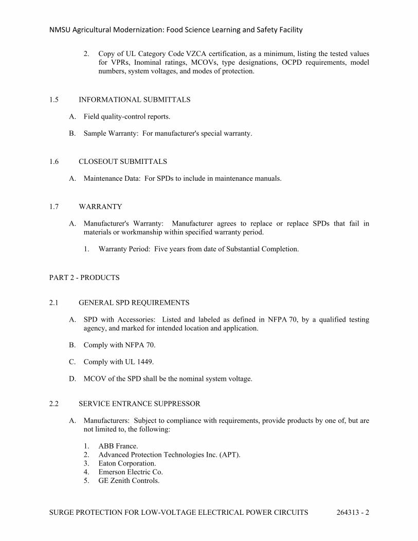
NMSU Agricultural Modernization: Food Science Learning and Safety Facility
SURGE PROTECTION FOR LOW-VOLTAGE ELECTRICAL POWER CIRCUITS 264313 - 2
2. Copy of UL Category Code VZCA certification, as a minimum, listing the tested values for VPRs, Inominal ratings, MCOVs, type designations, OCPD requirements, model numbers, system voltages, and modes of protection.
1.5 INFORMATIONAL SUBMITTALS
A. Field quality-control reports.
B. Sample Warranty: For manufacturer's special warranty.
1.6 CLOSEOUT SUBMITTALS
A. Maintenance Data: For SPDs to include in maintenance manuals.
1.7 WARRANTY
A. Manufacturer's Warranty: Manufacturer agrees to replace or replace SPDs that fail in materials or workmanship within specified warranty period.
1. Warranty Period: Five years from date of Substantial Completion.
PART 2 - PRODUCTS
2.1 GENERAL SPD REQUIREMENTS
A. SPD with Accessories: Listed and labeled as defined in NFPA 70, by a qualified testing agency, and marked for intended location and application.
B. Comply with NFPA 70.
C. Comply with UL 1449.
D. MCOV of the SPD shall be the nominal system voltage.
2.2 SERVICE ENTRANCE SUPPRESSOR
A. Manufacturers: Subject to compliance with requirements, provide products by one of, but are not limited to, the following:
1. ABB France.2. Advanced Protection Technologies Inc. (APT).3. Eaton Corporation.4. Emerson Electric Co.5. GE Zenith Controls.
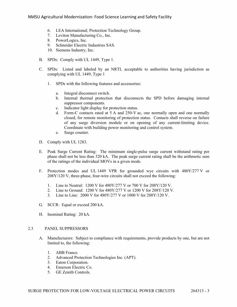
NMSU Agricultural Modernization: Food Science Learning and Safety Facility
SURGE PROTECTION FOR LOW-VOLTAGE ELECTRICAL POWER CIRCUITS 264313 - 3
6. LEA International; Protection Technology Group.7. Leviton Manufacturing Co., Inc.8. PowerLogics, Inc.9. Schneider Electric Industries SAS.10. Siemens Industry, Inc.
B. SPDs: Comply with UL 1449, Type 1.
C. SPDs: Listed and labeled by an NRTL acceptable to authorities having jurisdiction as complying with UL 1449, Type 1
1. SPDs with the following features and accessories:
a. Integral disconnect switch.b. Internal thermal protection that disconnects the SPD before damaging internal
suppressor components.c. Indicator light display for protection status.d. Form-C contacts rated at 5 A and 250-V ac, one normally open and one normally
closed, for remote monitoring of protection status. Contacts shall reverse on failure of any surge diversion module or on opening of any current-limiting device. Coordinate with building power monitoring and control system.
e. Surge counter.
D. Comply with UL 1283.
E. Peak Surge Current Rating: The minimum single-pulse surge current withstand rating per phase shall not be less than 320 kA. The peak surge current rating shall be the arithmetic sum of the ratings of the individual MOVs in a given mode.
F. Protection modes and UL 1449 VPR for grounded wye circuits with 480Y/277 V or 208Y/120 V, three-phase, four-wire circuits shall not exceed the following:
1. Line to Neutral: 1200 V for 480Y/277 V or 700 V for 208Y/120 V.2. Line to Ground: 1200 V for 480Y/277 V or 1200 V for 208Y/120 V.3. Line to Line: 2000 V for 480Y/277 V or 1000 V for 208Y/120 V.
G. SCCR: Equal or exceed 200 kA.
H. Inominal Rating: 20 kA.
2.3 PANEL SUPPRESSORS
A. Manufacturers: Subject to compliance with requirements, provide products by one, but are not limited to, the following:
1. ABB France.2. Advanced Protection Technologies Inc. (APT).3. Eaton Corporation.4. Emerson Electric Co.5. GE Zenith Controls.
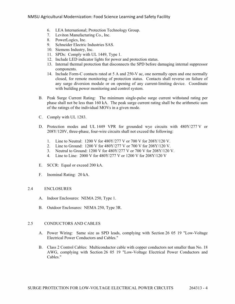
NMSU Agricultural Modernization: Food Science Learning and Safety Facility
SURGE PROTECTION FOR LOW-VOLTAGE ELECTRICAL POWER CIRCUITS 264313 - 4
6. LEA International; Protection Technology Group.7. Leviton Manufacturing Co., Inc.8. PowerLogics, Inc.9. Schneider Electric Industries SAS.10. Siemens Industry, Inc.11. SPDs: Comply with UL 1449, Type 1.12. Include LED indicator lights for power and protection status.13. Internal thermal protection that disconnects the SPD before damaging internal suppressor
components.14. Include Form-C contacts rated at 5 A and 250-V ac, one normally open and one normally
closed, for remote monitoring of protection status. Contacts shall reverse on failure of any surge diversion module or on opening of any current-limiting device. Coordinate with building power monitoring and control system.
B. Peak Surge Current Rating: The minimum single-pulse surge current withstand rating per phase shall not be less than 160 kA. The peak surge current rating shall be the arithmetic sum of the ratings of the individual MOVs in a given mode.
C. Comply with UL 1283.
D. Protection modes and UL 1449 VPR for grounded wye circuits with 480Y/277 V or 208Y/120V, three-phase, four-wire circuits shall not exceed the following:
1. Line to Neutral: 1200 V for 480Y/277 V or 700 V for 208Y/120 V.2. Line to Ground: 1200 V for 480Y/277 V or 700 V for 208Y/120 V.3. Neutral to Ground: 1200 V for 480Y/277 V or 700 V for 208Y/120 V.4. Line to Line: 2000 V for 480Y/277 V or 1200 V for 208Y/120 V
E. SCCR: Equal or exceed 200 kA.
F. Inominal Rating: 20 kA.
2.4 ENCLOSURES
A. Indoor Enclosures: NEMA 250, Type 1.
B. Outdoor Enclosures: NEMA 250, Type 3R.
2.5 CONDUCTORS AND CABLES
A. Power Wiring: Same size as SPD leads, complying with Section 26 05 19 "Low-Voltage Electrical Power Conductors and Cables."
B. Class 2 Control Cables: Multiconductor cable with copper conductors not smaller than No. 18 AWG, complying with Section 26 05 19 "Low-Voltage Electrical Power Conductors and Cables."
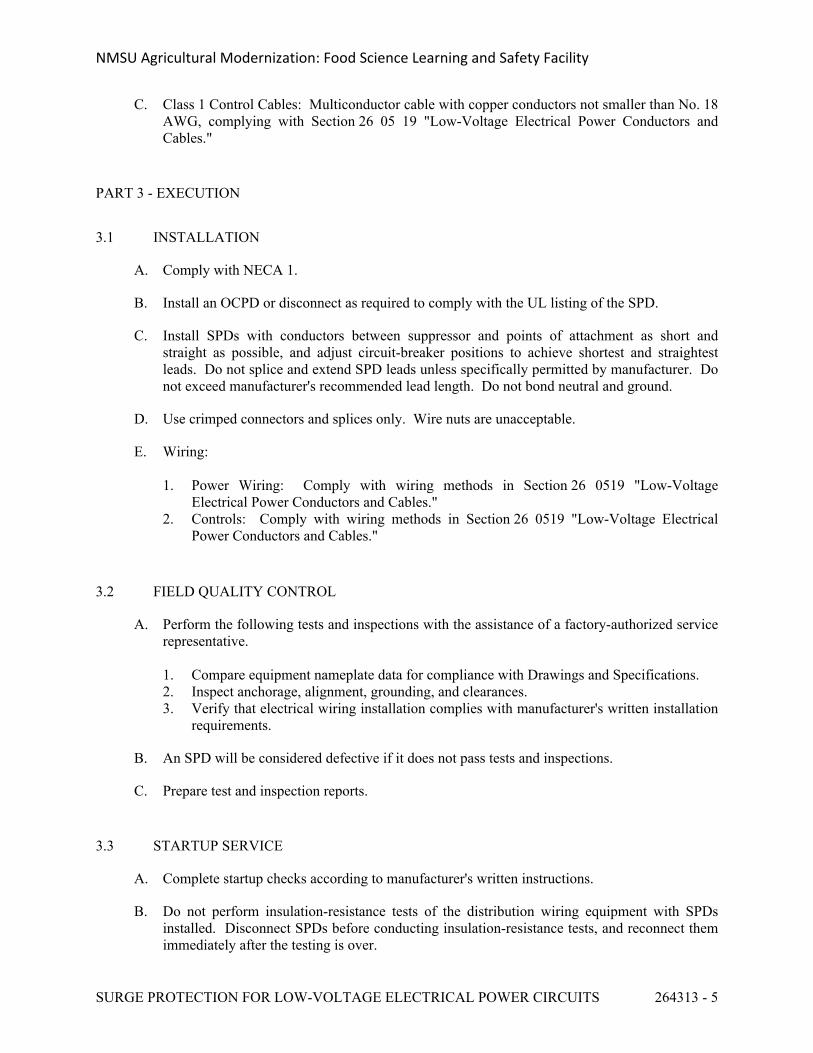
NMSU Agricultural Modernization: Food Science Learning and Safety Facility
SURGE PROTECTION FOR LOW-VOLTAGE ELECTRICAL POWER CIRCUITS 264313 - 5
C. Class 1 Control Cables: Multiconductor cable with copper conductors not smaller than No. 18 AWG, complying with Section 26 05 19 "Low-Voltage Electrical Power Conductors and Cables."
PART 3 - EXECUTION
3.1 INSTALLATION
A. Comply with NECA 1.
B. Install an OCPD or disconnect as required to comply with the UL listing of the SPD.
C. Install SPDs with conductors between suppressor and points of attachment as short and straight as possible, and adjust circuit-breaker positions to achieve shortest and straightest leads. Do not splice and extend SPD leads unless specifically permitted by manufacturer. Do not exceed manufacturer's recommended lead length. Do not bond neutral and ground.
D. Use crimped connectors and splices only. Wire nuts are unacceptable.
E. Wiring:
1. Power Wiring: Comply with wiring methods in Section 26 0519 "Low-Voltage Electrical Power Conductors and Cables."
2. Controls: Comply with wiring methods in Section 26 0519 "Low-Voltage Electrical Power Conductors and Cables."
3.2 FIELD QUALITY CONTROL
A. Perform the following tests and inspections with the assistance of a factory-authorized service representative.
1. Compare equipment nameplate data for compliance with Drawings and Specifications.2. Inspect anchorage, alignment, grounding, and clearances.3. Verify that electrical wiring installation complies with manufacturer's written installation
requirements.
B. An SPD will be considered defective if it does not pass tests and inspections.
C. Prepare test and inspection reports.
3.3 STARTUP SERVICE
A. Complete startup checks according to manufacturer's written instructions.
B. Do not perform insulation-resistance tests of the distribution wiring equipment with SPDs installed. Disconnect SPDs before conducting insulation-resistance tests, and reconnect them immediately after the testing is over.
NMSU Agricultural Modernization: Food Science Learning and Safety Facility
SURGE PROTECTION FOR LOW-VOLTAGE ELECTRICAL POWER CIRCUITS 264313 - 6
C. Energize SPDs after power system has been energized, stabilized, and tested.
3.4 DEMONSTRATION
A. Engage a factory-authorized service representative to train Owner's maintenance personnel to operate and maintain SPDs.
END OF SECTION 264313
NMSU Agricultural Modernization: Food Science Learning and Safety Facility
INTERIOR LIGHTING 265100 - 1
SECTION 265100 - INTERIOR LIGHTING
PART 1 - GENERAL
1.1 RELATED DOCUMENTS
A. Drawings and general provisions of the Contract, including General and Supplementary Conditions and Division 01 Specification Sections, apply to this Section.
1.2 SUMMARY
A. Section Includes:
1. Interior lighting fixtures, lamps, and ballasts.2. Emergency lighting units.3. Exit signs.4. Lighting fixture supports.5. Retrofit kits for fluorescent lighting fixtures.
B. Related Sections:
1. Section 26 2726 "Wiring Devices" for manual wall-box dimmers for incandescent lamps.
1.3 DEFINITIONS
A. BF: Ballast factor.
B. CCT: Correlated color temperature.
C. CRI: Color-rendering index.
D. HID: High-intensity discharge.
E. LER: Luminaire efficacy rating.
F. Lumen: Measured output of lamp and luminaire, or both.
G. Luminaire: Complete lighting fixture, including ballast housing if provided.
1.4 ACTION SUBMITTALS
A. Product Data: For each type of lighting fixture, arranged in order of fixture designation. Include data on features, accessories, finishes, and the following:
1. Physical description of lighting fixture including dimensions.2. Emergency lighting units including battery and charger.3. Ballast, including BF.
NMSU Agricultural Modernization: Food Science Learning and Safety Facility
INTERIOR LIGHTING 265100 - 2
4. Energy-efficiency data.5. Air and Thermal Performance Data: For air-handling lighting fixtures. Furnish data
required in "Action Submittals" Article in Section 23 3713 "Diffusers, Registers, and Grilles."
6. Sound Performance Data: For air-handling lighting fixtures. Indicate sound power level and sound transmission class in test reports certified according to standards specified in Section 23 3713 "Diffusers, Registers, and Grilles."
7. Life, output (lumens, CCT, and CRI), and energy-efficiency data for lamps.8. Photometric data and adjustment factors based on laboratory tests, complying with
IESNA Lighting Measurements Testing & Calculation Guides, of each lighting fixture type. The adjustment factors shall be for lamps, ballasts, and accessories identical to those indicated for the lighting fixture as applied in this Project.
a. Testing Agency Certified Data: For indicated fixtures, photometric data shall be certified by a qualified independent testing agency. Photometric data for remaining fixtures shall be certified by manufacturer.
b. Manufacturer Certified Data: Photometric data shall be certified by a manufacturer's laboratory with a current accreditation under the National Voluntary Laboratory Accreditation Program for Energy Efficient Lighting Products.
B. Shop Drawings: For nonstandard or custom lighting fixtures. Include plans, elevations, sections, details, and attachments to other work.
1. Detail equipment assemblies and indicate dimensions, weights, loads, required clearances, method of field assembly, components, and location and size of each field connection.
2. Wiring Diagrams: For power, signal, and control wiring.
C. Samples: For each lighting fixture indicated in the Interior Lighting Fixture Schedule. Each Sample shall include the following:
1. Lamps and ballasts, installed.2. Cords and plugs.3. Pendant support system.
D. Installation instructions.
1.5 INFORMATIONAL SUBMITTALS
A. Coordination Drawings: Reflected ceiling plan(s) and other details, drawn to scale, on which the following items are shown and coordinated with each other, using input from installers of the items involved:
1. Lighting fixtures.2. Suspended ceiling components.3. Partitions and millwork that penetrate the ceiling or extends to within 12 inches of the
plane of the luminaires.4. Ceiling-mounted projectors.5. Structural members to which suspension systems for lighting fixtures will be attached.
NMSU Agricultural Modernization: Food Science Learning and Safety Facility
INTERIOR LIGHTING 265100 - 3
6. Other items in finished ceiling including the following:
a. Air outlets and inlets.b. Speakers.c. Sprinklers.d. Smoke and fire detectors.e. Occupancy sensors.f. Access panels.
7. Perimeter moldings.
B. Qualification Data: For qualified agencies providing photometric data for lighting fixtures.
C. Product Certificates: For each type of ballast for bi-level and dimmer-controlled fixtures, from manufacturer.
D. Field quality-control reports.
E. Warranty: Sample of special warranty.
1.6 CLOSEOUT SUBMITTALS
A. Operation and Maintenance Data: For lighting equipment and fixtures to include in emergency, operation, and maintenance manuals.
1. Provide a list of all lamp types used on Project; use ANSI and manufacturers' codes.
1.7 MAINTENANCE MATERIAL SUBMITTALS
A. Furnish extra materials that match products installed and that are packaged with protective covering for storage and identified with labels describing contents.
1. Lamps: 10 for every 100 of each type and rating installed. Furnish at least one of each type.
2. Plastic Diffusers and Lenses: One for every 100 of each type and rating installed. Furnish at least one of each type.
3. Fluorescent-fixture-mounted, emergency battery pack: One for every 25 emergency lighting unit.
4. Ballasts: One for every 100 of each type and rating installed. Furnish at least one of each type.
5. Globes and Guards: One for every 20 of each type and rating installed. Furnish at least one of each type.
1.8 QUALITY ASSURANCE
A. Luminaire Photometric Data Testing Laboratory Qualifications: Provided by manufacturers' laboratories that are accredited under the National Volunteer Laboratory Accreditation Program for Energy Efficient Lighting Products.
NMSU Agricultural Modernization: Food Science Learning and Safety Facility
INTERIOR LIGHTING 265100 - 4
B. "Luminaire Photometric Data Testing Laboratory Qualifications" Paragraph below is to set qualifications for testing laboratories performing testing, in lighting fixture manufacturer's factory that are creating the photometric data required in "Action Submittals" Article.
C. Luminaire Photometric Data Testing Laboratory Qualifications: Provided by an independent agency, with the experience and capability to conduct the testing indicated, that is an NRTL as defined by OSHA in 29 CFR 1910, complying with the IESNA Lighting Measurements Testing & Calculation Guides.
D. Electrical Components, Devices, and Accessories: Listed and labeled as defined in NFPA 70, by a qualified testing agency, and marked for intended location and application.
E. Comply with NFPA 70.
F. FM Global Compliance: Lighting fixtures for hazardous locations shall be listed and labeled for indicated class and division of hazard by FM Global.
G. Mockups: Provide interior lighting fixtures for room or module mockups, complete with power and control connections.
1. Obtain Architect's approval of fixtures for mockups before starting installations.2. Maintain mockups during construction in an undisturbed condition as a standard for
judging the completed Work.3. Approved fixtures in mockups may become part of the completed Work if undisturbed at
time of Substantial Completion.
1.9 COORDINATION
A. Coordinate layout and installation of lighting fixtures and suspension system with other construction that penetrates ceilings or is supported by them, including HVAC equipment, fire-suppression system, and partition assemblies.
1.10 WARRANTY
A. Special Warranty for Emergency Lighting Batteries: Manufacturer's standard form in which manufacturer of battery-powered emergency lighting unit agrees to repair or replace components of rechargeable batteries that fail in materials or workmanship within specified warranty period.
1. Warranty Period for Emergency Lighting Unit Batteries: 5 years from date of Substantial Completion. Full warranty shall apply for first year, and prorated warranty for the remaining nine years.
2. Warranty Period for Emergency Fluorescent Ballast and Self-Powered Exit Sign Batteries: Seven years from date of Substantial Completion. Full warranty shall apply for first year, and prorated warranty for the remaining six years.
NMSU Agricultural Modernization: Food Science Learning and Safety Facility
INTERIOR LIGHTING 265100 - 5
PART 2 - PRODUCTS
2.1 MANUFACTURERS
A. Products: Subject to compliance with requirements with luminaires indicated on the luminaire schedule. Refer to schedule in the plans for approved luminaries on this project. Luminaires not on this schedule will not be approved for use or bidding on this project.
2.2 GENERAL REQUIREMENTS FOR LIGHTING FIXTURES AND COMPONENTS
A. Recessed Fixtures: Comply with NEMA LE 4 for ceiling compatibility for recessed fixtures.
B. Incandescent Fixtures: Comply with UL 1598. Where LER is specified, test according to NEMA LE 5A.
C. Fluorescent Fixtures: Comply with UL 1598. Where LER is specified, test according to NEMA LE 5 and NEMA LE 5A as applicable.
D. HID Fixtures: Comply with UL 1598. Where LER is specified, test according to NEMA LE 5B.
E. Metal Parts: Free of burrs and sharp corners and edges.
F. Sheet Metal Components: Steel unless otherwise indicated. Form and support to prevent warping and sagging.
G. Doors, Frames, and Other Internal Access: Smooth operating, free of light leakage under operating conditions, and designed to permit relamping without use of tools. Designed to prevent doors, frames, lenses, diffusers, and other components from falling accidentally during relamping and when secured in operating position.
H. Diffusers and Globes:
1. Acrylic Lighting Diffusers: 100 percent virgin acrylic plastic. High resistance to yellowing and other changes due to aging, exposure to heat, and UV radiation.
a. Lens Thickness: At least 0.125 inch minimum unless otherwise indicated.b. UV stabilized.
2. Glass: Annealed crystal glass unless otherwise indicated.
I. Factory-Applied Labels: Comply with UL 1598. Include recommended lamps and ballasts. Labels shall be located where they will be readily visible to service personnel, but not seen from normal viewing angles when lamps are in place.
1. Label shall include the following lamp and ballast characteristics:
a. "USE ONLY" and include specific lamp type.
NMSU Agricultural Modernization: Food Science Learning and Safety Facility
INTERIOR LIGHTING 265100 - 6
b. Lamp diameter code, T-8, tube configuration twin base type, and nominal wattage for fluorescent and compact fluorescent luminaires.
c. Start type rapid start or instant start for fluorescent luminaires.d. CCT and CRI for all luminaires.
2.3 BALLASTS FOR LINEAR FLUORESCENT LAMPS
A. General Requirements for Electronic Ballasts:
1. Comply with UL 935 and with ANSI C82.11.2. Designed for type and quantity of lamps served.3. Ballasts shall be designed for full light output unless another BF, dimmer, or bi-level
control is indicated.4. Sound Rating: Class A ballasts.5. Total Harmonic Distortion Rating: Less than 10 percent.6. Transient Voltage Protection: IEEE C62.41.1 and IEEE C62.41.2, Category A or better.7. Operating Frequency: 42 kHz or higher.8. Lamp Current Crest Factor: 1.7 or less.9. BF: 0.88 or higher.10. Power Factor: 0.98 or higher.11. Parallel Lamp Circuits: Multiple lamp ballasts shall comply with ANSI C82.11 and shall
be connected to maintain full light output on surviving lamps if one or more lamps fail.
B. Luminaires controlled by occupancy sensors shall have programmed-start ballasts.
C. Electronic Programmed-Start Ballasts for T8 Lamps: Comply with ANSI C82.11 and the following:
1. Lamp end-of-life detection and shutdown circuit for T5 diameter lamps.2. Automatic lamp starting after lamp replacement.
D. Electromagnetic Ballasts: Comply with ANSI C82.1; energy saving, high-power factor, Class P, and having automatic-reset thermal protection.
1. Ballast Manufacturer Certification: Indicated in luminaire schedule.
E. Single Ballasts for Multiple Lighting Fixtures: Factory wired with ballast arrangements and bundled extension wiring to suit final installation conditions without modification or rewiring in the field.
1. Control: Coordinate wiring from ballast to control device to ensure that the ballast, controller, and connecting wiring are compatible.
F. External Type: Self-contained, modular, battery-inverter unit, suitable for powering one or more fluorescent lamps, remote mounted from lighting fixture. Comply with UL 924.
1. Emergency Connection: Operate one fluorescent lamp continuously. Connect unswitched circuit to battery-inverter unit and switched circuit to fixture ballast.
2. Nightlight Connection: Operate one fluorescent lamp in a remote fixture continuously.3. Battery: Sealed, maintenance-free, nickel-cadmium type.
NMSU Agricultural Modernization: Food Science Learning and Safety Facility
INTERIOR LIGHTING 265100 - 7
4. Charger: Fully automatic, solid-state, constant-current type.5. Housing: NEMA 250, Type 1 enclosure.6. Test Push Button: Push-to-test type, in unit housing, simulates loss of normal power and
demonstrates unit operability.7. LED Indicator Light: Indicates normal power on. Normal glow indicates trickle charge;
bright glow indicates charging at end of discharge cycle.8. Remote Test: Switch in hand-held remote device aimed in direction of tested unit
initiates coded infrared signal. Signal reception by factory-installed infrared receiver in tested unit triggers simulation of loss of its normal power supply, providing visual confirmation of either proper or failed emergency response.
9. Integral Self-Test: Factory-installed electronic device automatically initiates code-required test of unit emergency operation at required intervals. Test failure is annunciated by an integral audible alarm and a flashing red LED.
2.4 EXIT SIGNS
A. General Requirements for Exit Signs: Comply with UL 924; for sign colors, visibility, luminance, and lettering size, comply with authorities having jurisdiction.
B. Internally Lighted Signs:
1. Lamps for AC Operation: Fluorescent, two for each fixture, 20,000 hours of rated lamp life.
2. Lamps for AC Operation: LEDs, 50,000 hours minimum rated lamp life.3. Self-Powered Exit Signs (Battery Type): Integral automatic charger in a self-contained
power pack.
a. Battery: Sealed, maintenance-free, nickel-cadmium type.b. Charger: Fully automatic, solid-state type with sealed transfer relay.c. Operation: Relay automatically energizes lamp from battery when circuit voltage
drops to 80 percent of nominal voltage or below. When normal voltage is restored, relay disconnects lamps from battery, and battery is automatically recharged and floated on charger.
d. Test Push Button: Push-to-test type, in unit housing, simulates loss of normal power and demonstrates unit operability.
e. LED Indicator Light: Indicates normal power on. Normal glow indicates trickle charge; bright glow indicates charging at end of discharge cycle.
f. Remote Test: Switch in hand-held remote device aimed in direction of tested unit initiates coded infrared signal. Signal reception by factory-installed infrared receiver in tested unit triggers simulation of loss of its normal power supply, providing visual confirmation of either proper or failed emergency response.
g. Integral Self-Test: Factory-installed electronic device automatically initiates code-required test of unit emergency operation at required intervals. Test failure is annunciated by an integral audible alarm and a flashing red LED.
NMSU Agricultural Modernization: Food Science Learning and Safety Facility
INTERIOR LIGHTING 265100 - 8
2.5 FLUORESCENT LAMPS
A. T8 rapid-start lamps, rated 25 W maximum, nominal length of 48 inches, 2800 initial lumens (minimum), CRI 75 (minimum), color temperature 3500K, and average rated life 20,000 hours unless otherwise indicated.
2.6 LIGHTING FIXTURE SUPPORT COMPONENTS
A. Comply with Section 26 0529 "Hangers and Supports for Electrical Systems" for channel- and angle-iron supports and nonmetallic channel and angle supports.
B. Single-Stem Hangers: 1/2-inch steel tubing with swivel ball fittings and ceiling canopy. Finish same as fixture.
C. Twin-Stem Hangers: Two, 1/2-inch steel tubes with single canopy designed to mount a single fixture. Finish same as fixture.
D. Wires: ASTM A 641/A 641M, Class 3, soft temper, zinc-coated steel, 12 gage.
E. Wires for Humid Spaces: ASTM A 580/A 580M, Composition 302 or 304, annealed stainless steel, 12 gage.
F. Rod Hangers: 3/16-inch minimum diameter, cadmium-plated, threaded steel rod.
G. Hook Hangers: Integrated assembly matched to fixture and line voltage and equipped with threaded attachment, cord, and locking-type plug.
PART 3 - EXECUTION
3.1 INSTALLATION
A. Lighting fixtures:
1. Set level, plumb, and square with ceilings and walls unless otherwise indicated.2. Install lamps in each luminaire.
B. Temporary Lighting: If it is necessary, and approved by Architect, to use permanent luminaires for temporary lighting, install and energize the minimum number of luminaires necessary. When construction is sufficiently complete, remove the temporary luminaires, disassemble, clean thoroughly, install new lamps, and reinstall.
C. Remote Mounting of Ballasts: Distance between the ballast and fixture shall not exceed that recommended by ballast manufacturer. Verify, with ballast manufacturers, maximum distance between ballast and luminaire.
D. Lay-in Ceiling Lighting Fixtures Supports: Use grid as a support element.
1. Install ceiling support system rods or wires, independent of the ceiling suspension devices, for each fixture. Locate not more than 6 inches from lighting fixture corners.
NMSU Agricultural Modernization: Food Science Learning and Safety Facility
INTERIOR LIGHTING 265100 - 9
2. Support Clips: Fasten to lighting fixtures and to ceiling grid members at or near each fixture corner with clips that are UL listed for the application.
3. Fixtures of Sizes Less Than Ceiling Grid: Install as indicated on reflected ceiling plans or center in acoustical panel, and support fixtures independently with at least two 3/4-inch metal channels spanning and secured to ceiling tees.
4. Install at least one independent support rod or wire from structure to a tab on lighting fixture. Wire or rod shall have breaking strength of the weight of fixture at a safety factor of 3.
E. Suspended Lighting Fixture Support:
1. Pendants and Rods: Where longer than 48 inches, brace to limit swinging.2. Stem-Mounted, Single-Unit Fixtures: Suspend with twin-stem hangers.3. Continuous Rows: Use tubing or stem for wiring at one point and tubing or rod for
suspension for each unit length of fixture chassis, including one at each end.4. Do not use grid as support for pendant luminaires. Connect support wires or rods to
building structure.
3.2 IDENTIFICATION
A. Install labels with panel and circuit numbers on concealed junction and outlet boxes. Comply with requirements for identification specified in Section 26 0553 "Identification for Electrical Systems."
3.3 FIELD QUALITY CONTROL
A. Test for Emergency Lighting: Interrupt power supply to demonstrate proper operation. Verify transfer from normal power to battery and retransfer to normal.
B. Verify that self-luminous exit signs are installed according to their listing and the requirements in NFPA 101.
C. Prepare a written report of tests, inspections, observations, and verifications indicating and interpreting results. If adjustments are made to lighting system, retest to demonstrate compliance with standards.
3.4 STARTUP SERVICE
A. Burn-in all lamps that require specific aging period to operate properly, prior to occupancy by Owner. Burn-in fluorescent and compact fluorescent lamps intended to be dimmed, for at least 100 hours at full voltage.
END OF SECTION 265100
NMSU Agricultural Modernization: Food Science Learning and Safety Facility
EXTERIOR LIGHTING 265612 - 1
SECTION 265612 – EXTERIOR LIGHTING
PART 1 - GENERAL
1.1 RELATED DOCUMENTS
A. Drawings and general provisions of the Contract, including General and Supplementary Conditions and Division 1 Specification Sections, apply to this Section.
1.2 SUMMARY
A. This Section includes exterior lighting fixtures, lamps, ballasts, pole standards, and accessories.
B. Related Sections: The following Sections contain requirements that relate to this Section:
1. Division 26, Section 26 5113, Interior Lighting Fixtures, Lamps and Ballasts for interior fixtures, lamps, ballasts, emergency lighting units, and accessories; also for exterior fixtures normally mounted on buildings.
2. Division 26, Section 26 0913, Lighting Control Equipment for programmable lighting control systems, time switches, photoelectric relays, power relays, and contactors.
1.3 DEFINITIONS
A. Fixture: A complete lighting device. Fixtures include a lamp or lamps and parts required to distribute light, position and protect lamps, and connect lamps to power supply, including a pole or bracket plus mounting and support accessories.
B. Luminaire: A fixture.
1.4 SUBMITTALS
A. General: Submit each item in this Article according to the Conditions of the Contract and Division 1 Specification Sections.
B. Product Data describing fixtures, lamps, ballasts, and accessories. Arrange Product Data for fixtures in order of fixture designation. Include data on features, accessories, finishes, and the following:
1. Outline drawings indicating dimensions and principal features of fixtures.2. Electrical Ratings and Photometric Data: Certified results of laboratory tests for fixtures
and lamps.
C. Wind Resistance Calculations: Certified by a registered professional engineer.
D. Shop Drawings detailing nonstandard fixtures and indicating dimensions, weights, method of field assembly, components, and accessories.
NMSU Agricultural Modernization: Food Science Learning and Safety Facility
EXTERIOR LIGHTING 265612 - 2
E. Wiring diagrams detailing wiring for control system showing both factory-installed and field-installed wiring for specific system of this Project, and differentiating between factory-installed and field-installed wiring.
F. Field test reports indicating and interpreting test results specified in Part 3 of this Section.
G. Maintenance data for products to include in the operation and maintenance manual specified in Division 1.
1.5 PRIOR APPROVAL
A. General: Submit each item in this article according to the conditions per prior approval outlined in Division 26, Section 26 05 00, Common Work Results for Electrical.
B. Provide a sample of the actual fixture proposed for approval.
C. Provide point-by-point calculations for areas served by proposed fixture. Coordinate requirements with the Architect.
1.6 QUALITY ASSURANCE
A. Electrical Component Standard: Provide components that comply with NFPA 70 and that are listed and labeled by UL where available.
B. Comply with ANSI C2.
C. Listing and Labeling: Provide fixtures and accessories specified in this Section that are listed and labeled for their indicated use and installation conditions on Project.
1. Special Listing and Labeling: Provide fixtures for use underwater that are specifically listed and labeled for such use. Provide fixtures for use in hazardous (classified) locations that are listed and labeled for the specific hazard.
2. The Terms "Listed" and "Labeled": As defined in the National Electrical Code, Article 100.
D. Fixtures for Hazardous Locations: Conform to UL 844. Provide units that have Factory Mutual Engineering and Research Corporation (FM) certification for indicated class and division of hazard.
1.7 WARRANTY
A. General Warranty: The special warranty specified in this Article shall not deprive the Owner of other rights the Owner may have under other provisions of the Contract Documents and shall be in addition to, and run concurrent with, other warranties made by the Contractor under requirements of the Contract Documents.
B. Special Warranty: Submit a written warranty signed by manufacturer and Installer agreeing to replace external parts of lighting fixtures exhibiting a failure of finish as specified below. This
NMSU Agricultural Modernization: Food Science Learning and Safety Facility
EXTERIOR LIGHTING 265612 - 3
warranty is in addition to, and not a limitation of, other rights and remedies the Owner may have under the Contract Documents.
1. Protection of Metal from Corrosion: Warranty against perforation or erosion of finish due to weathering.
2. Color Retention: Warranty against fading, staining, and chalking due to effects of weather and solar radiation.
PART 2 - PRODUCTS
2.1 MANUFACTURERS
A. Products: Subject to compliance with requirements, provide one of the products specified in each Exterior Lighting Unit Schedule on the drawings.
2.2 FIXTURES AND FIXTURE COMPONENTS, GENERAL
A. Metal Parts: Free from burrs, sharp edges, and corners.
B. Sheet Metal Components: Corrosion-resistant aluminum, except as otherwise indicated. Form and support to prevent warping and sagging.
C. Housings: Rigidly formed, weather- and light-tight enclosures that will not warp, sag, or deform in use. Provide filter/breather for enclosed fixtures.
D. Doors, Frames, and Other Internal Access: Smooth operating, free from light leakage under operating conditions, and arranged to permit relamping without use of tools. Arrange doors, frames, lenses, diffusers, and other pieces to prevent accidental falling during relamping and when secured in operating position. Provide for door removal for cleaning or replacing lens. Arrange for door opening to disconnect ballast.
E. Exposed Hardware Material: Stainless steel.
F. Reflecting Surfaces: Minimum reflectances as follows, except as otherwise indicated:
1. White Surfaces: 85 percent2. Specular Surfaces: 83 percent3. Diffusing Specular Surfaces: 75 percent
G. Plastic Parts: High resistance to yellowing and other changes due to aging, exposure to heat, and UV radiation.
H. Lenses and Refractors: Materials as indicated. Use heat- and aging-resistant, resilient gaskets to seal and cushion lens and refractor mounting in fixture doors.
I. Photoelectric Relays: Conform to UL 773.
1. Contact Relays: Single throw, arranged to fail in the ON position and factory set to turn light unit on at 1.5 to 3 foot-candles (16 to 32 lux) and off at 4.5 to 10 foot-candles (48 to
NMSU Agricultural Modernization: Food Science Learning and Safety Facility
EXTERIOR LIGHTING 265612 - 4
108 lux) with 15-second minimum time delay.2. Relay Mounting: In fixture housing.
J. Fluorescent Fixtures: Conform to UL 1570.
K. Fluorescent Ballasts: Class P, low-temperature, electromagnetic type, compatible with the lamps and lamp combinations to which connected.
1. Certification by Electrical Testing Laboratory (ETL).2. Labeling by Certified Ballast Manufacturers Association (CBM).3. Sound Rating: "A" rating, except as otherwise indicated.4. Voltage: Match connected circuits.5. Minimum Power Factor: 90 percent.6. Total Harmonic Distortion (THD) of Ballast Current: Less than 20 percent.7. Conform to FCC Regulations Part 15, Subpart J for electromagnetic interference.8. Conform to IEEE C62.41, Category A, for resistance to voltage surges for normal and
common modes.9. Minimum Starting Temperature: Minus 20 deg C.
L. High-Intensity-Discharge (HID) Fixtures: Conform to UL 1572.
M. HID Ballasts: Conform to UL 1029, and ANSI C82.4. Constant wattage autotransformer (CWA) or regulating high-power-factor type, unless otherwise indicated.
1. Ballast Fuses: One in each ungrounded supply conductor. Voltage and current ratings as recommended by ballast manufacturer.
2. Operating Voltage: Match system voltage.3. Single-Lamp Ballasts: Minimum starting temperature of minus 30 deg C.4. Open circuit operation will not reduce average life.5. High-Pressure Sodium (HPS) Ballasts: Equip with a solid-state igniter/starter having an
average life in pulsing mode of 10,000 hours at an igniter/starter case temperature of 90 deg C.
6. Noise: Uniformly quiet operation, with a noise rating of B or better.
N. Instant Restrike Device: Solid-state, potted module, mounted inside fixture and compatible with mogul-based HPS lamps, ballasts, and sockets up to 150 W.
1. Restrike Range: 105 to 130 VAC2. Maximum Voltage: 250 V peak or 150 VAC RMS
O. Auxiliary, Instant-On, Quartz System: Automatically switches quartz lamp when fixture is initially energized and when momentary power outages occur. Turns quartz lamp off automatically when HID lamp reaches approximately 60 percent light output. Mount control components internal to ballast and independent of incoming line voltage.
P. Incandescent Fixtures: Conform to UL 1571.
Q. Lamps: Comply with ANSI C78 series that is applicable to each type of lamp. Provide fixtures with indicated lamps of designated type, characteristics, and wattage. Where a lamp is not indicated for a fixture, provide medium wattage lamp recommended by manufacturer.
NMSU Agricultural Modernization: Food Science Learning and Safety Facility
EXTERIOR LIGHTING 265612 - 5
2.3 FIXTURE SUPPORT COMPONENTS
A. Mountings, Fastenings, and Appurtenances: Corrosion-resistant items compatible with support components. Use materials that will not cause galvanic action at contact points. Use mountings that correctly position luminaire to provide indicated light distribution.
2.4 FINISHES
A. Metal Parts: Manufacturer's standard finish, except as otherwise indicated, applied over corrosion-resistant primer, free of streaks, runs, holidays, stains, blisters, and similar defects.
B. Other Parts: Manufacturer's standard finish, except as otherwise indicated.
PART 3 - EXECUTION
3.1 INSTALLATION
A. Set units plumb, square, level, and secure according to manufacturer's written instructions and approved Shop Drawings.
B. Fixture Attachment: Fasten to indicated structural supports.
C. Fixture Attachment with Adjustable Features or Aiming: Attach fixtures and supports to allow aiming for indicated light distribution.
D. Lamp fixtures with indicated lamps according to manufacturer's written instructions. Replace malfunctioning lamps.
3.2 GROUNDING
A. Ground fixtures and metal poles according to Division 26, Section 26 0526, Grounding and Bonding for Electrical Systems.
3.3 FIELD QUALITY CONTROL
A. Inspect each installed unit for damage. Replace damaged fixtures and components.
B. Give advance notice of dates and times for field tests.
C. Provide instruments to make and record test results.
D. Tests and Observations: Verify normal operation of lighting units after installing fixtures and energizing circuits with normal power source.
E. Replace or repair damaged and malfunctioning units, make necessary adjustments, and retest.
NMSU Agricultural Modernization: Food Science Learning and Safety Facility
EXTERIOR LIGHTING 265612 - 6
Repeat procedure until all units operate properly.
3.4 ADJUSTING AND CLEANING
A. Clean units after installation. Use methods and materials recommended by manufacturer.
B. Adjust aimable fixtures to provide required light intensities.
3.5 EXTERIOR LIGHTING UNIT SCHEDULE
A. The luminaire schedule located in the construction drawings describes each type of luminaire for the project. Manufacturer’s catalog numbers are given for convenience. Where discrepancies occur between catalog numbers and the discipline information, the descriptive information shall take precedence. Some required features, options, accessory equipment or special order requirements may not be included in the catalog number.
END OF SECTION 265612
NMSU Agricultural Modernization: Food Science Learning and Safety Facility
GROUNDING AND BONDING FOR COMMUNICATIONS SYSTEMS 270526 - 1
SECTION 270526 - GROUNDING AND BONDING FOR COMMUNICATIONS SYSTEMS
PART 1 - GENERAL
1.1 RELATED DOCUMENTS
A. Drawings and general provisions of the Contract, including General and Supplementary Conditions and Division 01 Sections, apply to this Section
1.2 SUMMARY
A. Section Includes:
1. Grounding conductors.2. Grounding connectors.3. Grounding busbar.4. Grounding rods.5. Grounding labeling.
1.3 DEFINITIONS
A. BCT: Bonding conductor for telecommunications.
B. EMT: Electrical metallic tubing.
C. TGB: Telecommunications grounding busbar.
D. TMGB: Telecommunications main grounding busbar.
1.4 ACTION SUBMITTALS
A. Product Data: For each type of product.
B. Shop Drawings: For communications equipment room signal reference grid. Include plans, elevations, sections, details, and attachments to other work.
1.5 INFORMATIONAL SUBMITTALS
A. As-Built Data: Plans showing as-built locations of grounding and bonding infrastructure, including the following:
1. Ground rods.2. Ground and roof rings.3. BCT, TMGB, TGBs, and routing of their bonding conductors.

NMSU Agricultural Modernization: Food Science Learning and Safety Facility
GROUNDING AND BONDING FOR COMMUNICATIONS SYSTEMS 270526 - 2
B. Qualification Data: For Installer, installation supervisor, and field inspector.
C. Qualification Data: For testing agency and testing agencies field supervisor.
D. Field quality-control reports.
1.6 CLOSEOUT SUBMITTALS
A. Operation and Maintenance Data: For grounding to include in emergency, operation, and maintenance manuals.
1. In addition to items specified in Section 017823 "Operation and Maintenance Data," include the following:
a. Result of the ground-resistance test, measured at the point of BCT connection.b. Result of the bonding-resistance test at each TGB and its nearest grounding
electrode.
1.7 QUALITY ASSURANCE
A. Installer Qualifications: Cabling Installer must have personnel certified by BICSI on staff. (submit qualifications)
1. Layout Responsibility: Preparation of Shop Drawings and Cabling Administration Drawings, Cabling Administration Drawings and field testing program development by an RCDD.
2. Installation Supervision: Installation shall be under the direct supervision of a Registered Technician, or Level 2 Installer, who shall be present at all times when Work of this Section is performed at Project site.
3. Testing Supervisor: Currently certified by BICSI as an RCDD to supervise on-site testing.
B. Testing Agency Qualifications: An NRTL.
1. Testing Agency's Field Supervisor: Currently certified by BICSI as an RCDD to supervise on-site testing.
C. Surface-Burning Characteristics: As determined by testing identical products according to ASTM E 84 by a qualified testing agency. Identify products with appropriate markings of applicable testing agency.
1. Flame-Spread Index: 25 or less.2. Smoke-Developed Index: 50 or less.
D. Electrical Components, Devices, and Accessories: Listed and labeled as defined in NFPA 70, by a qualified testing agency, and marked for intended location and application.
E. Telecommunications Pathways and Spaces: Comply with TIA/EIA-569-C.
F. Grounding: Comply with TIA-607-B.
NMSU Agricultural Modernization: Food Science Learning and Safety Facility
GROUNDING AND BONDING FOR COMMUNICATIONS SYSTEMS 270526 - 3
1.8 QUALIFICATIONS
A. Communications Cabling: The Contractor shall have (5) five years of documented experience performing cable placement, splicing, termination, connecting, and testing for each of the media types and (3) three years of applicable experience with the proposed system manufacturer. In the case of newer technologies that do not have a (3) three year history, the Contractor shall have documented experience for at least half of the lifetime of the new technology. The approved contractor shall, at a minimum, maintain a ratio of one manufacturer or BICSI certified installer for every two non-certified installers assigned to the project.
B. The contractor shall have on staff a BICSI Certified RCDD as a permanent employee. This staff member shall have been on staff for a minimum of (1) one year prior to the date of this projects release for bid.
C. The contractor shall have on staff at least (1) one BICSI Certified Technician and this staff member shall have been a full time employee for no less than (1) one year prior to the date of this projects release for bid. A BICSI Certified Technician shall be employed as the on-site Field Supervisor for this project.
D. The contractor shall provide resumes for the Project Manager, Supervisors and any skilled technicians or installers. Each resume shall include applicable certification documents provided by the manufacturer or BICSI.
1. Project Manager, Supervisors, and Principal Skilled Technicians: minimum of (5) five years’ experience in like work.
2. Category 6 Unshielded Twisted Pair and Fiber Optic Cable Technicians: documented training, licensing, and/or certification for the types of media specified, as applicable as well as certification from the manufacturer of the solution chosen by the owner.
PART 2 - PRODUCTS
2.1 SYSTEM DESCRIPTION
A. Electrical Components, Devices, and Accessories: Listed and labeled as defined in NFPA 70, by a qualified testing agency, and marked for intended location and application.
B. Comply with UL 467 for grounding and bonding materials and equipment.
C. Comply with TIA-607-B.
2.2 CONDUCTORS
A. Manufacturers: Subject to compliance with requirements. Provide products by one of the following available manufacturers that may be incorporated into the Work include, but are not limited to, the following:
1. Harger Lightning and Grounding.2. Panduit Corp.
NMSU Agricultural Modernization: Food Science Learning and Safety Facility
GROUNDING AND BONDING FOR COMMUNICATIONS SYSTEMS 270526 - 4
3. Tyco Electronics Corp.
B. Comply with UL 486A-486B.
C. Insulated Conductors: Stranded copper wire, green or green with yellow stripe insulation, insulated for 600 V, and complying with UL 83.
1. Ground wire for custom-length equipment ground jumpers shall be No. 6 AWG, 19-strand, UL-listed, Type THHN wire.
2. Cable Tray Equipment Grounding Wire: No. 6 AWG.
D. Bare Copper Conductors:
1. Solid Conductors: ASTM B 3.2. Stranded Conductors: ASTM B 8.3. Tinned Conductors: ASTM B 33.4. Bonding Cable: 28 kcmils (14.2 sq. mm), 14 strands of No. 17 AWG conductor and 1/4
inch, (6.3 mm), in diameter.5. Bonding Conductor No. 6 AWG, stranded conductor.6. Bonding Jumper: Tinned-copper tape, braided conductors terminated with two-hole
copper ferrules; 1-5/8 inches (41 mm) wide and 1/16 inch (1.6 mm) thick.
2.3 CONNECTORS
A. Irreversible connectors listed for the purpose. Listed by an NRTL as complying with NFPA 70 for specific types, sizes, and combinations of conductors and other items connected. Comply with UL 486A-486B.
B. Manufacturers: Subject to compliance with requirements, provide products by the following available manufacturers offering products that may be incorporated into the work include, but are not limited to, the following:
1. Burndy; Part of Hubbell Electrical Systems.2. Chatsworth Products, Inc.3. Harger Lightning and Grounding.4. Panduit Corp.5. Tyco Electronics Corp.
C. Compression Wire Connectors: Crimp-and-compress connectors that bond to the conductor when the connector is compressed around the conductor. Comply with UL 467.
1. Electroplated tinned copper, C and H shaped.
D. Busbar Connectors: Cast silicon bronze, solder-less compression or exothermic-type, mechanical connector; with a long barrel and two holes spaced on 5/8- or 1-inch, (15.8- or 25.4-mm), centers for a two-bolt connection to the busbar.
E. Welded Connectors: Exothermic-welding kits of types recommended by kit manufacturer for materials being joined and installation conditions.
NMSU Agricultural Modernization: Food Science Learning and Safety Facility
GROUNDING AND BONDING FOR COMMUNICATIONS SYSTEMS 270526 - 5
2.4 GROUNDING BUSBARS
A. Manufacturers: Subject to compliance with requirements, provide products by the following available manufacturers offering products that may be incorporated into the Work include, but are not limited to, the following:
1. Chatsworth Products, Inc.2. Harger Lightning and Grounding.3. Panduit Corp.
B. TMGB: Predrilled, wall-mounted, rectangular bars of hard-drawn solid copper, 1/4 by 4 inches, (6.3 by 100 mm), in cross section, length as indicated on Drawings. The busbar shall be NRTL listed for use as TMGB and shall comply with TIA/EIA-607-B.
1. Predrilling shall be for use with lugs specified in this Section.2. Mounting Hardware: Stand-off brackets that provide a 4-inch (100-mm) clearance to
access the rear of the busbar. Brackets and bolts shall be stainless steel.3. Stand-off insulators for mounting shall be Lexan or PVC. Comply with UL 891 for use in
600-V switchboards, impulse tested at 5000 V.
C. TGB: Predrilled rectangular bars of hard-drawn solid copper, 1/4 by 2 inches (6.3 by 50mm), in cross section, length as indicated on Drawings. The busbar shall be for wall mounting, shall be NRTL listed as complying with UL 467 and shall comply with TIA/EIA-607-B.
1. Predrilling shall be with holes for use with lugs specified in this Section.2. Mounting Hardware: Stand-off brackets that provide at least a 2-inch, (50-mm), clearance
to access the rear of the busbar. Brackets and bolts shall be stainless steel.3. Stand-off insulators for mounting shall be Lexan or PVC. Comply with UL 891 for use in
600-V switchboards and impulse tested at 5000 V.
D. Rack and Cabinet Grounding Busbar: Rectangular bars of hard-drawn solid copper, accepting conductors ranging from No. 14 to No. 2/0 AWG, NRTL listed as complying with UL 467 and complying with TIA/EIA-607-B. Predrilling shall be with holes for use with lugs specified in this Section.
1. Cabinet-Mounted Busbar: Terminal block, with stainless-steel or copper-plated hardware for attachment to the cabinet.
2. Rack-Mounted Horizontal Busbar: Designed for mounting in 19- or 23-inch (483- or 584-mm) equipment racks. Include a copper splice bar for transitioning to an adjoining rack, and stainless-steel or copper-plated hardware for attachment to the rack.
3. Rack-Mounted Vertical Busbar: 72 or 36 inches, (1827 or 914 mm long, with), stainless-steel or copper-plated hardware for attachment to the rack.
2.5 GROUND RODS
A. Manufacturers: Subject to compliance with requirements, provide products by one of the following available manufacturers offering products that may be incorporated into the Work include, but are not limited to, the following:
NMSU Agricultural Modernization: Food Science Learning and Safety Facility
GROUNDING AND BONDING FOR COMMUNICATIONS SYSTEMS 270526 - 6
1. Harger Lightning and Grounding.2. Tyco Electronics Corp.
B. Ground Rods: Copper-clad, Zinc-coated, Stainless steel, sectional type, 3/4 inch by 10 feet, (19 mm by 3 m), 5/8 by 96 inches, (16 by 2400 mm), in diameter.
2.6 LABELING
A. Manufacturers: Subject to compliance with requirements, provide products by one of the following available manufacturers offering products that may be incorporated into the Work include, but are not limited to, the following:
1. Brother International Corporation.2. HellermannTyton.3. Panduit Corp.
B. Comply with TIA/EIA-606-B and UL 969 for a system of labeling materials, including label stocks, laminating adhesives and inks used by label printers.
C. Machine printed, in black, by thermal transfer or equivalent process. Minimum letter height shall be 3/8 inch (10 mm). Overlay shall provide a weatherproof and UV-resistant seal for label.
PART 3 - EXECUTION
3.1 EXAMINATION
A. Examine the ac grounding electrode system and equipment grounding for compliance with requirements for maximum ground-resistance level and other conditions affecting performance of grounding and bonding of the electrical system.
B. Inspect the test results of the ac grounding system measured at the point of BCT connection.
C. Prepare written report, endorsed by Installer, listing conditions detrimental to performance of the Work.
D. Proceed with connection of the BCT only after unsatisfactory conditions have been corrected.
3.2 INSTALLATION
A. Bonding shall include the ac utility power service entrance, the communications cable entrance, and the grounding electrode system. The bonding of these elements shall form a loop so that each element is connected to at least two others.
B. Comply with NECA 1.
C. Comply with TIA/EIA-607-B.
NMSU Agricultural Modernization: Food Science Learning and Safety Facility
GROUNDING AND BONDING FOR COMMUNICATIONS SYSTEMS 270526 - 7
3.3 APPLICATION
A. Conductors: Install solid conductor for No. 8AWG and smaller and stranded conductors for No. 6 AWG and larger unless otherwise indicated.
1. The bonding conductors between the TGB and structural steel of steel-frame buildings shall not be smaller than No. 6 AWG.
2. The bonding conductors between the TMGB and structural steel of steel-frame buildings shall not be smaller than No. 6 AWG.
B. Underground Grounding Conductors: Install bare tinned- copper conductor, No. 2 AWG minimum.
C. Conductor Terminations and Connections:
1. Pipe and Equipment Grounding Conductor Terminations: Bolted connectors.2. Underground Connections: Welded connectors except at test wells and as otherwise
indicated.3. Connections to Ground Rods at Test Wells: Bolted connectors.4. Connections to Structural Steel: Welded connectors.
Conductor Support:
5. Secure grounding and bonding conductors at intervals of not less than 36 inches (900 mm.)
D. Grounding and Bonding Conductors:
1. Install in the straightest and shortest route between the origination and termination point, and no longer than required. The bend radius shall not be smaller than eight times the diameter of the conductor. No one bend may exceed 90 degrees.
2. Install without splices.3. Support at not more than 36-inch (900-mm) intervals.4. Install grounding and bonding conductors in 3/4-inch (21-mm) PVC conduit until conduit
enters a telecommunications room. The grounding and bonding conductor pathway through a plenum shall be in EMT. Conductors shall not be installed in EMT unless otherwise indicated.
a. If grounding and bonding conductor is installed in ferrous metallic conduit, bond the conductor to the conduit using a grounding bushing that complies with requirements in Section 270528 "Pathways for Communications Systems," and bond both ends of the conduit to a TGB.
3.4 GROUNDING ELECTRODE SYSTEM
A. The BCT between the TMBG and the ac service equipment ground shall not be smaller than No. 3/0AWG.
NMSU Agricultural Modernization: Food Science Learning and Safety Facility
GROUNDING AND BONDING FOR COMMUNICATIONS SYSTEMS 270526 - 8
3.5 GROUNDING BUSBARS
A. Indicate locations of grounding busbars on Drawings. Install busbars horizontally, on insulated spacers 2 inches, (50 mm), minimum from wall and 12 inches, (300 mm), above finished floor unless otherwise indicated.
B. Where indicated on both sides of doorways, route bus up to top of door frame, across top of doorway, and down; connect to horizontal bus.
3.6 CONNECTIONS
A. Bond metallic equipment in a telecommunications equipment room to the grounding busbar in that room, using equipment grounding conductors not smaller than No. 6 AWG.
B. Stacking of conductors under a single bolt is not permitted when connecting to busbars.
C. Assemble the wire connector to the conductor, complying with manufacturer's written instructions and as follows:
1. Use crimping tool and the die specific to the connector.2. Pre-twist the conductor.3. Apply an antioxidant compound to all bolted and compression connections.
D. Primary Protector: Bond to the TMGB with insulated bonding conductor.
E. Interconnections: Interconnect all TGBs and the TMGB with the telecommunications backbone conductor. If more than one TMGB is installed, interconnect TMGBs using the grounding equalizer conductor. The telecommunications backbone conductor and grounding equalizer conductor size shall not be less than 2 kcmils/linear foot, (1 sq. mm/linear meter), of conductor length and up to a maximum size of No. 3/0 AWG 168 kcmils, (85 sq. mm), unless otherwise indicated.
F. Telecommunications Enclosures and Equipment Racks: Bond metallic components of enclosures to the telecommunications bonding and grounding system. Install top-mounted or vertically mounted rack grounding busbar unless the enclosure and rack are manufactured with the busbar. Bond the equipment grounding busbar to the TGB utilizing No. 6 AWG bonding conductors.
G. Structural Steel: Where the structural steel of a steel frame building is readily accessible within the room or space, bond each TGB and TMGB to the vertical steel of the building frame.
H. Electrical Power Panelboards: Where an electrical panelboard for telecommunications equipment is located in the same room or space, bond each TGB to the ground bar of the panelboard.
I. Shielded Cable: Bond the shield of shielded cable to the TGB in communications rooms and spaces. Comply with TIA/EIA-568-C.1 and TIA/EIA-568-C.2 when grounding screened, balanced, twisted-pair cables.
NMSU Agricultural Modernization: Food Science Learning and Safety Facility
GROUNDING AND BONDING FOR COMMUNICATIONS SYSTEMS 270526 - 9
J. Rack- and Cabinet-Mounted Equipment: Bond powered equipment chassis to the cabinet or rack grounding bar. Power connection shall comply with NFPA 70; the equipment grounding conductor in the power cord of cord- and plug-connected equipment shall be considered as a supplement to bonding requirements in this Section.
K. Access Floors: Bond all metal parts of access floors to the TGB.
3.7 IDENTIFICATION
A. Labels shall be preprinted or computer-printed type.
1. Label TMGB(s) with "ts-TMGB," where "ts" is the telecommunications space identifier for the space containing the TMGB.
2. Label TGB(s) with "ts-TGB," where "ts" is the telecommunications space identifier for the space containing the TGB.
3. Label the BCT and each telecommunications backbone conductor at its attachment point: "WARNING! TELECOMMUNICATIONS BONDING CONDUCTOR. DO NOT REMOVE OR DISCONNECT!"
3.8 FIELD QUALITY CONTROL
A. Perform tests and inspections.
B. Tests and Inspections:
1. Inspect physical and mechanical condition. Verify tightness of accessible, bolted, electrical connections with a calibrated torque wrench according to manufacturer's written instructions.
2. Test the bonding connections of the system using an ac earth ground-resistance tester, taking two-point bonding measurements in each telecommunications equipment room containing a TMGB and a TGB and using the process recommended in the BICSI TDMM. Conduct tests with the facility in operation.
a. Measure the resistance between the busbar and the nearest available grounding electrode. The maximum acceptable value of this bonding resistance is 100 milliohms.
3. Test for ground loop currents using a digital clamp-on ammeter, with a full-scale of not more than 10 A, displaying current in increments of 0.01 A at an accuracy of plus/minus 2.0 percent.
a. With the grounding infrastructure completed and the communications system electronics operating, measure the current in every conductor connected to the TMGB and each TGB. Maximum acceptable ac current level is 1 A.
C. Excessive Ground Resistance: If resistance to ground at the BCT exceeds 5ohms, notify Architect promptly and include recommendations to reduce ground resistance.
D. Grounding system will be considered defective if it does not pass tests and inspections.
NMSU Agricultural Modernization: Food Science Learning and Safety Facility
GROUNDING AND BONDING FOR COMMUNICATIONS SYSTEMS 270526 - 10
E. Prepare test and inspection reports.
END OF SECTION 270526
NMSU Agricultural Modernization: Food Science Learning and Safety Facility
PATHWAYS FOR COMMUNICATIONS SYSTEMS 270528 - 1
SECTION 270528 - PATHWAYS FOR COMMUNICATIONS SYSTEMS
PART 1 - GENERAL
1.1 RELATED DOCUMENTS
A. Drawings and general provisions of the Contract, including General and Supplementary Conditions and Division 01 Sections, apply to this Section
1.2 SUMMARY
A. Section Includes:
1. Metal conduits and fittings.2. Nonmetallic conduits and fittings.3. Optical-fiber-cable pathways and fittings.4. Boxes, enclosures, and cabinets.5. Handholes and boxes for exterior underground cabling.
B. Related Requirements:
1. Section 26 0533 "Raceways and Boxes for Electrical Systems" for conduits, wireways, surface raceways, boxes, enclosures, cabinets, handholes, and faceplate adapters serving electrical systems.
2. Section 28 0528 "Pathways for Electronic Safety and Security" for conduits, surface pathways, innerduct, boxes, and faceplate adapters serving electronic safety and security.
3. Section 27 0536 “Cable Trays for Communication Systems”
1.3 ACTION SUBMITTALS
A. Product data for the following:
1. Surface pathways2. Wireways and fittings.3. Tele-power poles.4. Boxes, enclosures, and cabinets.5. Underground handholes and boxes.
B. Sustainable Design Submittals:
1. Product Data for Credit IEQ 4.1: For solvent cements and adhesive primers, documentation including printed statement of VOC content.
2. Laboratory Test Reports for Credit IEQ 4: For solvent cements and adhesive primers, documentation indicating that products comply with the testing and product requirements of the California Department of Health Services' "Standard Practice for the Testing of
NMSU Agricultural Modernization: Food Science Learning and Safety Facility
PATHWAYS FOR COMMUNICATIONS SYSTEMS 270528 - 2
Volatile Organic Emissions from Various Sources Using Small-Scale Environmental Chambers."
C. Shop Drawings: For custom enclosures and cabinets. Include plans, elevations, sections, and attachment details.
1.4 QUALITY ASSURANCE
A. Installer Qualifications: Cabling Installer must have personnel certified by BICSI on staff. (submit qualifications)
1. Layout Responsibility: Preparation of Shop Drawings and Cabling Administration Drawings, Cabling Administration Drawings and field testing program development by an RCDD.
2. Installation Supervision: Installation shall be under the direct supervision of a Registered Technician, or Level 2 Installer, who shall be present at all times when Work of this Section is performed at Project site.
3. Testing Supervisor: Currently certified by BICSI as an RCDD to supervise on-site testing.
B. Testing Agency Qualifications: An NRTL.
1. Testing Agency's Field Supervisor: Currently certified by BICSI as an RCDD to supervise on-site testing.
C. Surface-Burning Characteristics: As determined by testing identical products according to ASTM E 84 by a qualified testing agency. Identify products with appropriate markings of applicable testing agency.
1. Flame-Spread Index: 25 or less.2. Smoke-Developed Index: 50 or less.
D. Electrical Components, Devices, and Accessories: Listed and labeled as defined in NFPA 70, by a qualified testing agency, and marked for intended location and application.
E. Telecommunications Pathways and Spaces: Comply with TIA/EIA-569-C.
F. Grounding: Comply with TIA-607-B.
1.5 QUALIFICATIONS
A. Communications Cabling: The Contractor shall have (5) five years of documented experience performing cable placement, splicing, termination, connecting, and testing for each of the media types and (3) three years of applicable experience with the proposed system manufacturer. In the case of newer technologies that do not have a (3) three year history, the Contractor shall have documented experience for at least half of the lifetime of the new technology. The approved contractor shall, at a minimum, maintain a ratio of one manufacturer or BICSI certified installer for every two non-certified installers assigned to the project.
NMSU Agricultural Modernization: Food Science Learning and Safety Facility
PATHWAYS FOR COMMUNICATIONS SYSTEMS 270528 - 3
B. The contractor shall have on staff a BICSI Certified RCDD as a permanent employee. This staff member shall have been on staff for a minimum of (1) one year prior to the date of this projects release for bid.
C. The contractor shall have on staff at least (1) one BICSI Certified Technician and this staff member shall have been a full time employee for no less than (1) one year prior to the date of this projects release for bid. A BICSI Certified Technician shall be employed as the on-site Field Supervisor for this project.
D. The contractor shall provide resumes for the Project Manager, Supervisors and any skilled technicians or installers. Each resume shall include applicable certification documents provided by the manufacturer or BICSI.
1. Project Manager, Supervisors, and Principal Skilled Technicians: minimum of (5) five years’ experience in like work.
2. Category 6 Unshielded Twisted Pair and Fiber Optic Cable Technicians: documented training, licensing, and/or certification for the types of media specified, as applicable as well as certification from the manufacturer of the solution chosen by the owner.
1.6 INFORMATIONAL SUBMITTALS
A. Coordination Drawings: Pathway routing plans, drawn to scale, on which the following items are shown and coordinated with each other, using input from installers of items involved:
1. Structural members in paths of pathway groups with common supports.2. HVAC and plumbing items and architectural features in paths of conduit groups with
common supports.
B. Qualification Data: For professional engineer.
C. Seismic Qualification Certificates: For pathway racks, enclosures, cabinets, equipment racks and their mounting provisions, including those for internal components, from manufacturer.
1. Basis for Certification: Indicate whether withstand certification is based on actual test of assembled components or on calculation.
2. Dimensioned Outline Drawings of Equipment Unit: Identify center of gravity and locate and describe mounting and anchorage provisions.
3. Detailed description of equipment anchorage devices on which certification is based and their installation requirements.
4. Detailed description of conduit support devices and interconnections on which certification is based and their installation requirements.
D. Source quality-control reports.
NMSU Agricultural Modernization: Food Science Learning and Safety Facility
PATHWAYS FOR COMMUNICATIONS SYSTEMS 270528 - 4
PART 2 - PRODUCTS
2.1 METAL CONDUITS AND FITTINGS
A. General Requirements for Metal Conduits and Fittings:
1. Listed and labeled as defined in NFPA 70, by a qualified testing agency, and marked for intended location and application.
2. Comply with TIA-569-C.
B. EMT: Comply with ANSI C80.3 and UL 797.
C. Fittings for Metal Conduit: Comply with NEMA FB 1 and UL 514B.
1. Conduit Fittings for Hazardous (Classified) Locations: Comply with UL 886 and NFPA 70.
2. Fittings for EMT:
a. Material: Steel or die cast.b. Type: Setscrew or compression.
3. Expansion Fittings: PVC or steel to match conduit type, complying with UL-467, rated for environmental conditions, where installed and including flexible external bonding jumper.
D. Joint Compound for GRC or ARC: Approved, as defined in NFPA 70, by authorities having jurisdiction for use in conduit assemblies and compounded for use to lubricate and protect threaded conduit joints from corrosion, to enhance their conductivity.
E. Flexible Conduit will not be permitted.
2.2 NONMETALLIC CONDUITS AND FITTINGS
A. General Requirements for Nonmetallic Conduits and Fittings:
1. Listed and labeled as defined in NFPA 70, by a qualified testing agency and marked for intended location and application.
2. Comply with TIA-569-C.
B. RNC: Type EPC-40-PVC, complying with NEMA TC 2 and UL 651 unless otherwise indicated.
C. Continuous HDPE: Comply with UL 651B.
D. Fittings for RNC: Comply with NEMA TC 3; match to conduit or tubing type and material.
E. Solvent cements and adhesive primers shall have a VOC content of 510 and 550 g/L or less, respectively, when calculated according to 40 CFR 59, Subpart D (EPA Method 24).
NMSU Agricultural Modernization: Food Science Learning and Safety Facility
PATHWAYS FOR COMMUNICATIONS SYSTEMS 270528 - 5
F. Solvent cements and adhesive primers shall comply with the testing and product requirements of the California Department of Health Services' "Standard Practice for the Testing of Volatile Organic Emissions from Various Sources Using Small-Scale Environmental Chambers."
2.3 OPTICAL-FIBER-CABLE PATHWAYS AND FITTINGS
A. Description: Comply with UL 2024; flexible-type pathway, approved for plenum riser or general-use installation unless otherwise indicated.
1. Listed and labeled as defined in NFPA 70, by a qualified testing agency, and marked for intended location and application.
2. Comply with TIA-569-C.
2.4 HOOKS
A. Description: Prefabricated sheet metal cable supports for telecommunications cable.
B. Listed and labeled as defined in NFPA 70, by an NRTL, and marked for intended location and application.
C. Comply with TIA-569-C.
D. Manufacturers: Subject to compliance with requirements, provide products by one of the following available manufacturers offering products that may be incorporated into the Work include, but are not limited to, the following:
1. Cooper B- Line System #781011 04762#781011 04874#781011 04770#781011 04875
2. Erico Caddy Cat HP System3. Erico Caddy Cat CM System4. Owner or Consultant approved equal.
E. Galvanized or stainless steel.
F. J shape.
2.5 BOXES, ENCLOSURES, AND CABINETS
A. General Requirements for Boxes, Enclosures, and Cabinets:
1. Comply with TIA-569-C.2. Boxes, enclosures and cabinets installed in wet locations shall be listed for use in wet
locations.
B. Cast-Metal Outlet and Device Boxes: Comply with NEMA FB 1, ferrous alloy aluminum, Type FD, with a gasketed cover.
NMSU Agricultural Modernization: Food Science Learning and Safety Facility
PATHWAYS FOR COMMUNICATIONS SYSTEMS 270528 - 6
C. Box extensions used to accommodate new building finishes shall be of same material as recessed box.
D. Metal Floor Boxes:
1. Material: Cast metal or sheet metal.2. Type: Fully adjustable, Semi-adjustable.3. Listing and Labeling: Metal floor boxes shall be listed and labeled as defined in NFPA 70,
by a qualified testing agency, and marked for intended location and application.
E. Nonmetallic Floor Boxes: Nonadjustable, round or rectangular.
1. Listing and Labeling: Nonmetallic floor boxes shall be listed and labeled as defined in NFPA 70, by a qualified testing agency, and marked for intended location and application.
F. Cast-Metal Access, Pull, and Junction Boxes: Comply with NEMA FB 1 and UL 1773, cast aluminum or galvanized, cast iron with gasketed cover.
G. Device Box Dimensions: 4 inches square by 2-1/8 inches deep (100 mm square by 60 mm deep) or 4 inches by 2-1/8 inches by 2-1/8 inches deep (100 mm by 60 mm by 60 mm deep).
H. Gangable boxes are prohibited.
I. Nonmetallic Outlet and Device Boxes: Comply with NEMA OS 2 and UL 514C.
J. Coordinate "Hinged-Cover Enclosures" Paragraph below with Drawings if hinged cover enclosures other than NEMA 250, Type 1 are required, such as for very dusty areas; or if consideration should be given to use of NEMA 250, Type 3R or Type 12 enclosures.
K. Hinged-Cover Enclosures: Comply with UL 50 and NEMA 250, Type 1, Type 3R, Type 4 and Type 12, (dependent on environmental conditions), with continuous-hinge cover with flush latch unless otherwise indicated.
1. Metal Enclosures: Steel, finished inside and out with manufacturer's standard enamel.2. Nonmetallic Enclosures: Plastic or fiberglass, finished inside with radio-frequency-
resistant paint.3. Interior Panels: Steel; all sides finished with manufacturer's standard enamel.
L. Cabinets:
1. NEMA 250, Type 1, Type 3R, Type 12, (dependent on environmental conditions), galvanized-steel box with removable interior panel and removable front, finished inside and out with manufacturer's standard enamel.
2. Hinged door in front cover with flush latch and concealed hinge.3. Key latch to match panelboards.4. Metal barriers to separate wiring of different systems and voltage.5. Accessory feet where required for freestanding equipment.6. Nonmetallic cabinets shall be listed and labeled as defined in NFPA 70, by a qualified
testing agency and marked for intended location and application.
NMSU Agricultural Modernization: Food Science Learning and Safety Facility
PATHWAYS FOR COMMUNICATIONS SYSTEMS 270528 - 7
2.6 PRECAST CONCRETE HANDHOLES AND BOXES
A. Manufacturers: Subject to compliance with requirements, available manufacturers offering products that may be incorporated into the Work include, but are not limited to, the following:
1. Christy Concrete Products.2. Elmhurst-Chicago Stone Co.3. Oldcastle Precast Group.4. Rinker Group, Ltd.5. Riverton Concrete Products.6. Utility Concrete Products, LLC.7. Utility Vault Co.8. Wausau Tile Inc.
B. Comply with ASTM C 858 for design and manufacturing processes.
C. Description: Factory-fabricated, reinforced-concrete, monolithically poured walls and bottom unless open-bottom enclosures are indicated. Frame and cover shall form top of enclosure and shall have load rating consistent with that of handhole or box.
1. Retain one of four "Frame and Cover" subparagraphs below; revise to specify features of frame and cover assembly. Consult manufacturers for additional frame and cover designs.
2. Frame and Cover: Weatherproof steel frame, with hinged steel access door assembly with tamper-resistant, captive, cover-securing bolts.
a. Cover Hinges: Concealed, with hold-open ratchet assembly.b. Cover Handle: Recessed.
3. Cover Finish: Nonskid finish shall have a minimum coefficient of friction of 0.50.4. Cover Legend: Molded lettering, "COMMUNICATIONS."5. Configuration: Units shall be designed for flush burial and have closed bottom with
centered 12” diameter hole for drainage.6. Extensions and Slabs: Designed to mate with bottom of enclosure. Same material as
enclosure.
a. Extension shall provide increased depth of 12 inches (300 mm).b. Slab: Same dimensions as bottom of enclosure, and arranged to provide closure.
7. Joint Sealant: Asphaltic-butyl material with adhesion, cohesion, flexibility, and durability properties necessary to withstand maximum hydrostatic pressures at the installation location with the ground-water level at grade.
8. Windows: Precast openings in walls, arranged to match dimensions and elevations of approaching ducts and duct banks, plus an additional 12 inches (300 mm) vertically and horizontally to accommodate alignment variations.
a. Windows shall be located no less than 6 inches (150 mm) from interior surfaces of walls, floors, or frames and covers of handholes, but close enough to corners to facilitate racking of cables on walls.
b. Window opening shall have cast-in-place, welded-wire fabric reinforcement for field cutting and bending to tie in to concrete envelopes of duct banks.
NMSU Agricultural Modernization: Food Science Learning and Safety Facility
PATHWAYS FOR COMMUNICATIONS SYSTEMS 270528 - 8
c. Window openings shall be framed with at least two additional No. 3 steel reinforcing bars in concrete around each opening.
9. Duct Entrances in Handhole Walls: Cast end-bell or duct-terminating fitting in wall for each entering duct.
a. Type and size shall match fittings to duct or conduit to be terminated.b. Fittings shall align with elevations of approaching ducts and be located near interior
corners of handholes to facilitate racking of cable.
10. Handholes 48 inches wide by 48 inches long (1200 mm wide by 1200 mm long) and larger shall have inserts for cable racks and pulling-in irons installed before concrete is poured.
2.7 HANDHOLES AND BOXES FOR EXTERIOR UNDERGROUND CABLING
A. General Requirements for Handholes and Boxes:
1. Boxes and handholes for use in underground systems shall be designed and identified as defined in NFPA 70, for intended location and application.
2. Boxes installed in wet areas shall be listed and labeled as defined in NFPA 70, by a qualified testing agency and marked for intended location and application.
3. Comply with TIA-569-C.4. Handholes/Manholes shall be traffic rated when installed in parking lots, access roads and
streets.
B. Polymer-Concrete Handholes and Boxes with Polymer-Concrete Cover: Molded of sand and aggregate, bound together with polymer resin and reinforced with steel, fiberglass, or a combination of the two.
1. Standard: Comply with SCTE 77.2. Configuration: Designed for flush burial with open, closed, integral closed, bottom unless
otherwise indicated.3. Cover: Weatherproof, secured by tamper-resistant locking devices and having structural
load rating consistent with enclosure and handhole location.4. Cover Finish: Nonskid finish shall have a minimum coefficient of friction of 0.50.5. Cover Legend: Molded lettering, "COMMUNICATIONS."
PART 3 - EXECUTION
3.1 PATHWAY APPLICATION
A. Outdoors: Apply pathway products as specified below unless otherwise indicated:
1. Exposed Conduit: EMT, RNC, Type EPC-40-PVC, RNC and Type EPC-80-PVC.2. Concealed Conduit, Aboveground: EMT, RNC, Type EPC-40-PVC.3. Underground Conduit: RNC, Type EPC-40-PVC Type EPC-80-PVC, direct buried
concrete encased.4. Boxes and Enclosures, above ground: NEMA 250, Type 3R Type 4.
NMSU Agricultural Modernization: Food Science Learning and Safety Facility
PATHWAYS FOR COMMUNICATIONS SYSTEMS 270528 - 9
B. Indoors: Apply pathway products as specified below unless otherwise indicated:
1. Exposed, Not Subject to Physical Damage: EMT or RNC.2. Exposed, Not Subject to Severe Physical Damage: EMT, RNC identified for such use.3. Concealed in Ceilings and Interior Walls and Partitions: EMT RNC, Type EPC-40-PVC
or inner duct.4. Pathways for Optical-Fiber or Communications Cable in Spaces Used for Environmental
Air: Plenum-type, optical-fiber-cable pathway, Plenum-type, communications-cable pathway, EMT.
5. Pathways for Optical-Fiber or Communications-Cable Risers in Vertical Shafts: Riser-type, optical-fiber-cable pathway. Riser-type, communications-cable pathway EMT.
6. Pathways for Concealed General-Purpose Distribution of Optical-Fiber or Communications Cable: General-use, optical-fiber-cable pathway Riser-type, optical-fiber-cable pathway. Plenum-type, optical-fiber-cable pathway. General-use, communications-cable pathway. Riser-type, communications-cable pathway. Plenum-type, communications-cable pathway. EMT.
7. Boxes and Enclosures: NEMA 250 Type 1, except use NEMA 250 Type 4 stainless steel nonmetallic in institutional and commercial kitchens and damp or wet locations.
C. Minimum Pathway Size: 1 inch (27mm) trade size. Minimum size for optical-fiber cables is 1 inch (27 mm).
D. Pathway Fittings: Compatible with pathways and suitable for use and location.
1. Rigid Steel Conduit: Use threaded rigid steel conduit fittings unless otherwise indicated. Comply with NEMA FB 2.10.
2. EMT: Use setscrew or compression, steel and cast-metal fittings. Comply with NEMA FB 2.10.
E. Do not install aluminum conduits, boxes, or fittings in contact with concrete or earth.
F. Install surface pathways only where indicated on Drawings.
G. Do not install nonmetallic conduit where ambient temperature exceeds 120 deg. F, (49 deg. C).
3.2 INSTALLATION
A. Comply with NECA 1, NECA 101, and TIA-569-C for installation requirements except where requirements on Drawings or in this article are stricter. Comply with NECA 102 for aluminum pathways. Comply with NFPA 70 limitations for types of pathways allowed in specific occupancies and number of floors.
B. Keep pathways at least 6 inches (150 mm) away from parallel runs of flues and steam or hot-water pipes. Install horizontal pathway runs above water and steam piping.
C. Comply with requirements in Section 260529 "Hangers and Supports for Electrical Systems" for hangers and supports.
D. Arrange stub-ups so curved portions of bends are not visible above finished slab.
NMSU Agricultural Modernization: Food Science Learning and Safety Facility
PATHWAYS FOR COMMUNICATIONS SYSTEMS 270528 - 10
E. Install no more than the equivalent of two 90-degree bends in any pathway run. Support within 12 inches (300 mm) of changes in direction. Utilize long radius ells for all optical-fiber cables.
F. Conceal conduit and EMT within finished walls, ceilings, and floors unless otherwise indicated. Install conduits parallel or perpendicular to building lines.
G. Pathways Embedded in Slabs:
1. Run conduit larger than 1-inch (27-mm) trade size, parallel or at right angles to main reinforcement. Where at right angles to reinforcement, place conduit close to slab support. Secure pathways to reinforcement at maximum 10-foot (3-m) intervals.
2. Arrange pathways to cross building expansion joints at right angles with expansion fittings.3. Arrange pathways to keep a minimum of 1 inch, (25 mm), of concrete cover in all
directions.4. Do not embed threadless fittings in concrete unless specifically approved by Architect for
each specific location.
H. Stub-ups to Above Recessed Ceilings:
1. Use a conduit bushing or insulated fitting to terminate stub-ups not terminated in hubs or in an enclosure.
I. Coat field-cut threads on PVC-coated pathway with a corrosion-preventing conductive compound prior to assembly.
J. Terminate threaded conduits into threaded hubs or with locknuts on inside and outside of boxes or cabinets. Install insulated bushings on conduits terminated with locknuts.
K. Install pathways square to the enclosure and terminate at enclosures with locknuts. Install locknuts hand tight plus 1/4 turn more.
L. Do not rely on locknuts to penetrate nonconductive coatings on enclosures. Remove coatings in the locknut area prior to assembling conduit to enclosure to assure a continuous ground path.
M. Spare Pathways: Install pull wires in empty pathways. Cap underground pathways designated as spare above grade alongside pathways in use.
N. Surface Pathways:
1. Install surface pathway for surface telecommunications outlet boxes only where indicated on Drawings.
O. "Pathways for Optical-Fiber and Communications Cable" Paragraph below is applicable for EMT, RMC, RNC, and optical-fiber and communications-cable pathways.
P. Pathways for Optical-Fiber and Communications Cable: Install pathways as follows:
1. 1-Inch (27-mm) Trade Size and Larger: Install pathways in maximum lengths of 75 feet (23 m).
2. Install with a maximum of two 90-degree bends or equivalent for each length of pathway unless Drawings show stricter requirements.
NMSU Agricultural Modernization: Food Science Learning and Safety Facility
PATHWAYS FOR COMMUNICATIONS SYSTEMS 270528 - 11
Q. Install pathway sealing fittings at accessible locations according to NFPA 70 and fill them with listed sealing compound.
R. Locate seals so no fittings or boxes are between the seal and the following changes of environments. Seal the interior of all pathways at the following points:
1. Where conduits pass from warm to cold locations, such as boundaries of refrigerated spaces.
2. Where an underground service pathway enters a building or structure.3. Where otherwise required by NFPA 70.
S. Expansion-Joint Fittings:
1. Install in each run of aboveground RNC that is located where environmental temperature change may exceed 30 deg. F, (17 deg. C) and that has straight-run length that exceeds 25 feet, (7.6 m). Install in each run of aboveground RMC and EMT conduit that is located where environmental temperature change may exceed 100 deg. F, (55 deg. C) and that has straight-run length that exceeds 100 feet, (30 m).
2. Install type and quantity of fittings that accommodate temperature change listed for each of the following locations:
a. Outdoor Locations Not Exposed to Direct Sunlight: 125 deg. F, (70 deg. C), temperature change.
b. Outdoor Locations Exposed to Direct Sunlight: 155 deg. F, (86 deg. C), temperature change.
c. Indoor Spaces Connected with Outdoors without Physical Separation: 125 deg. F, (70 deg. C), temperature change.
d. Ceilings and Attics: 135 deg. F, (75 deg. C), temperature change.
3. Install fitting(s) that provide expansion and contraction for at least 0.00041 inch per foot of length of straight run per deg. F, (0.06 mm per meter of length of straight run per deg. (C), of temperature change for PVC conduits. Install fitting(s) that provide expansion and contraction for at least 0.000078 inch per foot of length of straight run per deg., F, (0.0115), mm per meter of length of straight run per deg., ( C), of temperature change for metal conduits.
4. Install expansion fittings at all locations where conduits cross building or structure expansion joints.
5. Install each expansion-joint fitting with position, mounting, and piston setting selected according to manufacturer's written instructions for conditions at specific location at time of installation. Install conduit supports to allow for expansion movement.
T. Mount boxes at heights indicated on Drawings in accordance with ADA requirements. Install boxes with height measured to bottom of box unless otherwise indicated.
U. Horizontally separate boxes mounted on opposite sides of walls so they are not in the same vertical channel.
V. Hooks:
NMSU Agricultural Modernization: Food Science Learning and Safety Facility
PATHWAYS FOR COMMUNICATIONS SYSTEMS 270528 - 12
1. Size to allow a minimum of 25 percent future capacity without exceeding design capacity limits.
2. Shall be supported by dedicated support wires. Do not use ceiling grid support wire or support rods.
3. Hook spacing shall allow no more than 6 inches (150 mm) of slack. The lowest point of the cables shall be no less than 6 inches (150 mm) adjacent to ceilings, mechanical ductwork and fittings, luminaires, power conduits, power and telecommunications outlets, and other electrical and communications equipment.
4. Space hooks no more than 4 feet (1.5 m) o.c.5. Provide a hook at each change in direction.
3.3 INSTALLATION OF UNDERGROUND CONDUIT
A. Direct-Buried Conduit:
1. Excavate trench bottom to provide firm and uniform support for conduit. Prepare trench bottom as specified in Section 31 2000 "Earth Moving" for pipe less than 6 inches, (150 mm), in nominal diameter.
2. Install backfill as specified in Section 31 2000 "Earth Moving."3. After installing conduit, backfill and compact. After placing controlled backfill to within
12 inches, (300 mm), of finished grade, make final conduit connection at end of run and complete backfilling with normal compaction as specified in Section 31 2000, "Earth Moving."
4. Install manufactured rigid steel conduit elbows for stub-ups at poles and equipment and at building entrances through floor.
a. Couple steel conduits to ducts with adapters designed for this purpose, and encase coupling with 3 inches, (75 mm), of concrete for a minimum of 12 inches, (300 mm), on each side of the coupling.
b. For stub-ups at equipment mounted on outdoor concrete bases and where conduits penetrate building foundations, extend steel conduit horizontally a minimum of 60 inches, (1500 mm), from edge of foundation or equipment base. Install insulated grounding bushings on terminations at equipment.
5. Underground Warning Tape: Comply with requirements in Section 260553 "Identification for Electrical Systems."
3.4 INSTALLATION OF UNDERGROUND HANDHOLES AND BOXES
A. Install handholes and boxes level and plumb and with orientation and depth coordinated with connecting conduits to minimize bends and deflections required for proper entrances.
B. Elevation: In paved areas, set so cover surface will be flush with finished grade. Set covers of other enclosures 1 inch, (25 mm), above finished grade.
C. Install handholes with bottom below frost line, in accordance with manufacturer’s specifications.
D. Field cut openings for conduits according to enclosure manufacturer's written instructions.
NMSU Agricultural Modernization: Food Science Learning and Safety Facility
PATHWAYS FOR COMMUNICATIONS SYSTEMS 270528 - 13
3.5 SLEEVE AND SLEEVE-SEAL INSTALLATION FOR COMMUNICATIONS PENETRATIONS
A. Install sleeves and sleeve seals at penetrations of exterior floor and wall assemblies. Comply with requirements in Section 27 0544, "Sleeves and Sleeve Seals for Communications Pathways and Cabling."
3.6 FIRESTOPPING
A. Install firestopping at penetrations of fire-rated floor and wall assemblies. Comply with requirements in Section 07 8413, "Penetration Firestopping."
3.7 PROTECTION
A. Protect coatings, finishes, and cabinets from damage or deterioration.
1. Repair damage to galvanized finishes with zinc-rich paint recommended by manufacturer.2. Repair damage to PVC coatings or paint finishes with matching touchup coating
recommended by manufacturer.
END OF SECTION 27 0528
NMSU Agricultural Modernization: Food Science Learning and Safety Facility
CABLE TRAYS FOR COMMUNICATIONS SYSTEMS 270536 - 1
SECTION 270536 - CABLE TRAYS FOR COMMUNICATIONS SYSTEMS
PART 1 - GENERAL
1.1 RELATED DOCUMENTS
A. Drawings and general provisions of the Contract, including General and Supplementary Conditions and Division 01 Sections, apply to this Section
1.2 SUMMARY
A. Section Includes: Contractor is responsible for providing and installing a complete Cable tray system that meets or exceeds the specifications listed below.
1. Ladder cable trays, Contractor is to install cable trays within the ER/TR’s.2. Wire-basket cable trays. Contractor is to install all cable trays outside of the ER/TR,s
B. Related Requirements:
1. Section 26 0536 "Cable Trays for Electrical Systems" for cable trays and accessories serving electrical systems.
1.3 ACTION SUBMITTALS
A. Product Data: For each type of cable tray.
1. Include data indicating dimensions and finishes for each type of cable tray indicated.
B. Shop Drawings: For each type of cable tray.
1. Show fabrication and installation details of cable trays, including plans, elevations, and sections of components and attachments to other construction elements. Designate components and accessories, including clamps, brackets, hanger rods, splice-plate connectors, expansion-joint assemblies, straight lengths, and fittings.
2. Cable tray layout, showing cable tray route to scale, with relationship between the tray and adjacent structural, electrical, and mechanical elements. Include the following:
a. Vertical and horizontal offsets and transitions.b. Clearances for access above and to sides of cable trays.c. Vertical elevation of cable trays above the floor or bottom of ceiling structure.d. Load calculations to show dead and live loads as not exceeding manufacturer's rating
for tray and its support elements.
C. Delegated-Design Submittal: For seismic restraints.
1. Seismic-Restraint Details: Signed and sealed by a qualified professional engineer, licensed in the state where Project is located, who is responsible for their preparation.
2. Design Calculations: Calculate requirements for selecting seismic restraints.
NMSU Agricultural Modernization: Food Science Learning and Safety Facility
CABLE TRAYS FOR COMMUNICATIONS SYSTEMS 270536 - 2
3. Detail fabrication, including anchorages and attachments to structure and to supported cable trays.
1.4 QUALITY ASSURANCE
A. Installer Qualifications: Cabling Installer must have personnel certified by BICSI on staff. (submit qualifications)
1. Layout Responsibility: Preparation of Shop Drawings and Cabling Administration Drawings, Cabling Administration Drawings and field testing program development by an RCDD.
2. Installation Supervision: Installation shall be under the direct supervision of a Registered Technician, or Level 2 Installer, who shall be present at all times when Work of this Section is performed at Project site.
3. Testing Supervisor: Currently certified by BICSI as an RCDD to supervise on-site testing.
B. Testing Agency Qualifications: An NRTL.
1. Testing Agency's Field Supervisor: Currently certified by BICSI as an RCDD to supervise on-site testing.
C. Surface-Burning Characteristics: As determined by testing identical products according to ASTM E 84 by a qualified testing agency. Identify products with appropriate markings of applicable testing agency.
1. Flame-Spread Index: 25 or less.2. Smoke-Developed Index: 50 or less.
D. Electrical Components, Devices, and Accessories: Listed and labeled as defined in NFPA 70, by a qualified testing agency, and marked for intended location and application.
E. Telecommunications Pathways and Spaces: Comply with TIA/EIA-569-C.
F. Grounding: Comply with TIA-607-B.
1.5 QUALIFICATIONS
A. Communications Cabling: The Contractor shall have (5) five years of documented experience performing cable placement, splicing, termination, connecting, and testing for each of the media types and (3) three years of applicable experience with the proposed system manufacturer. In the case of newer technologies that do not have a (3) three year history, the Contractor shall have documented experience for at least half of the lifetime of the new technology. The approved
NMSU Agricultural Modernization: Food Science Learning and Safety Facility
CABLE TRAYS FOR COMMUNICATIONS SYSTEMS 270536 - 3
contractor shall, at a minimum, maintain a ratio of one manufacturer or BICSI certified installer for every two non-certified installers assigned to the project.
B. The contractor shall have on staff a BICSI Certified RCDD as a permanent employee. This staff member shall have been on staff for a minimum of (1) one year prior to the date of this projects release for bid.
C. The contractor shall have on staff at least (1) one BICSI Certified Technician and this staff member shall have been a full time employee for no less than (1) one year prior to the date of this projects release for bid. A BICSI Certified Technician shall be employed as the on-site Field Supervisor for this project.
D. The contractor shall provide resumes for the Project Manager, Supervisors and any skilled technicians or installers. Each resume shall include applicable certification documents provided by the manufacturer or BICSI.
1. Project Manager, Supervisors, and Principal Skilled Technicians: minimum of (5) five years’ experience in like work.
2. Category 6 Unshielded Twisted Pair and Fiber Optic Cable Technicians: documented training, licensing, and/or certification for the types of media specified, as applicable as well as certification from the manufacturer of the solution chosen by the owner.
1.6 INFORMATIONAL SUBMITTALS
A. Coordination Drawings: Floor plans and sections, drawn to scale, on which the following items are shown and coordinated with each other, using input from installers of the items involved:
1. Scaled cable tray layout and relationships between components and adjacent structural, electrical, and mechanical elements.
2. Vertical and horizontal offsets and transitions.3. Clearances for access above and to side of cable trays.4. Vertical elevation of cable trays above the floor or below bottom of ceiling structure.
B. Seismic Qualification Data: Certificates, for cable trays, accessories, and components, from manufacturer.
1. Basis for Certification: Indicate whether withstand certification is based on actual test of assembled components or on calculation.
2. Dimensioned Outline Drawings of Equipment Unit: Identify center of gravity and locate and describe mounting and anchorage provisions.
3. Detailed description of equipment anchorage devices on which the certification is based and their installation requirements.
C. Field quality-control reports..
NMSU Agricultural Modernization: Food Science Learning and Safety Facility
CABLE TRAYS FOR COMMUNICATIONS SYSTEMS 270536 - 4
PART 2 - PRODUCTS
2.1 PERFORMANCE REQUIREMENTS
A. Delegated Design: Engage a qualified professional engineer, as defined in Section 014000 "Quality Requirements," to design cable tray supports and seismic bracing.
B. Seismic Performance: Cable trays and supports shall withstand the effects of earthquake motions determined according to ASCE/SEI 7.
1. Component Importance Factor: 1.5, 1.0.
2.2 GENERAL REQUIREMENTS FOR CABLE TRAYS
A. Cable Trays and Accessories: Identified as defined in NFPA 70 and marked for intended location, application, and grounding.
1. Source Limitations: Obtain cable trays and components from single manufacturer.
B. Sizes and Configurations: See the Cable Tray Schedule on Drawings for specific requirements for types, materials, sizes, and configurations.
C. Structural Performance: See articles for individual cable tray types for specific values for the following parameters:
1. Uniform Load Distribution: Capable of supporting a uniformly distributed load on the indicated support span when supported as a simple span and tested according to NEMA VE 1.
2. Concentrated Load: A load applied at midpoint of span and centerline of tray.3. Load and Safety Factors: Applicable to both side rails and rung capacities.
2.3 LADDER CABLE TRAY
A. Manufacturers: Subject to compliance with requirements, provide products by the following:
1. CPI Chatsworth, Contractor Provided
B. Description:
1. Configuration: Two longitudinal side rails with transverse rungs swaged or welded to side rails, complying with NEMA VE 1.
2. Width: as indicated on Drawings.3. Straight Section Lengths: 10 feet (3.0 m) except where shorter lengths are required to
facilitate tray assembly.4. Rung Spacing: 9 inches (225 mm)o.c.5. Radius-Fitting Rung Spacing: 9 inches (225 mm) at center of tray's width.6. Minimum Cable-Bearing Surface for Rungs: 7/8-inch (22-mm) width with radius edges.7. No portion of the rungs shall protrude below the bottom plane of side rails.
NMSU Agricultural Modernization: Food Science Learning and Safety Facility
CABLE TRAYS FOR COMMUNICATIONS SYSTEMS 270536 - 5
8. Structural Performance of Each Rung: Capable of supporting a maximum cable load, with a safety factor of 1.5, plus a 200-lb (90-kg) concentrated load, when tested according to NEMA VE 1.
9. Class Designation: Comply with NEMA VE 1, Class 5A, Class 8A10. Splicing Assemblies: Bolted type using serrated flange locknuts.11. Splice-Plate Capacity: Splices located within support span shall not diminish rated loading
capacity of cable tray.
C. Materials and Finishes:
1. Steel:
a. Straight Section and Fitting Side Rails and Rungs: Steel complies with the minimum mechanical properties of ASTM A 1011/A 1011M, SS, Grade 33.
b. Steel Tray Splice Plates: ASTM A 1011/A 1011M, HSLAS, Grade 50, Class 1.c. Fasteners: Steel complies with the minimum mechanical properties of
ASTM A 510/A 510M, Grade 1008.
d. Finish: Powder-coat enamel paint.
1) Powder-Coat Enamel: Cable tray manufacturer's recommended primer and corrosion-inhibiting treatment, with factory-applied powder-coat paint.
2) Hardware: Chromium-zinc plated, ASTM F 1136 or Stainless steel, Type 316, ASTM F 593 and ASTM F 594.
2.4 WIRE-BASKET CABLE TRAYS
A. Manufacturers: Subject to compliance with requirements, provide products by the following:
1. CPI Chatsworth, Contractor Provided
B. Description:
1. Configuration: Galvanized- steel wire mesh, complying with NEMA VE 1.2. Width: 12 inches (300 mm) unless otherwise indicated on Drawings.3. Straight Section Lengths: 10 feet (3.0 m), except where shorter lengths are required to
facilitate tray assembly.4. Structural Performance: Capable of supporting a maximum cable load, with a safety factor
of 1.5, plus a 200-lb (90-kg) concentrated load, when tested according to NEMA VE 1.5. Class Designation: Comply with NEMA VE 1, Class 8A.6. Splicing Assemblies: Bolted type using serrated flange locknuts.7. Splice-Plate Capacity: Splices located within support span shall not diminish rated loading
capacity of cable tray.
C. Materials and Finishes:
1. Steel:a. Straight Sections and Fittings: Steel complies with the minimum mechanical
properties of ASTM A 1011/A 1011M, SS, Grade 33b. Steel Tray Splice Plates: ASTM A 1011/A 1011M, HSLAS, Grade 50, Class 1.
NMSU Agricultural Modernization: Food Science Learning and Safety Facility
CABLE TRAYS FOR COMMUNICATIONS SYSTEMS 270536 - 6
c. Fasteners: Steel complies with the minimum mechanical properties of ASTM A 510/A 510M, Grade 1008.
d. Finish: Hot-dip galvanized after fabrication, complying with ASTM A123/A123 M, Class B2.1) Hardware: Galvanized, ASTM B 633 or Chromium-zinc plated,
ASTM F 1136 or Stainless steel, Type 316.e. Finish: Powder-coat enamel paint.
1) Powder-Coat Enamel: Cable tray manufacturer's recommended primer and corrosion-inhibiting treatment, with factory-applied powder-coat paint.
2) Hardware: Chromium-zinc plated, ASTM F 1136 or Stainless steel, Type 316, ASTM F 593 and ASTM F 594.
2.5 CABLE TRAY ACCESSORIES
A. Fittings: Tees, crosses, risers, elbows and other fittings as indicated, of same materials and finishes as cable tray.
B. Barrier Strips: Same materials and finishes as for cable tray.
C. Cable tray supports and connectors, including bonding jumpers, as recommended by cable tray manufacturer.
2.6 WARNING SIGNS
A. Lettering: 1-1/2-inch, (40-mm-), high, black letters on yellow background with legend "Warning! Not To Be Used as Walkway, Ladder, or Support for Ladders or Personnel."
B. Comply with requirements for fasteners in Section 260553 "Identification for Electrical Systems."
2.7 SOURCE QUALITY CONTROL
A. Testing: Test and inspect cable trays according to NEMA VE 1.
PART 3 - EXECUTION
3.1 CABLE TRAY INSTALLATION
A. Install cable trays according to NEMA VE 2.
B. Install cable trays as a complete system, including fasteners, hold-down clips, support systems, barrier strips, adjustable horizontal and vertical splice plates, elbows, reducers, tees, crosses, cable dropouts, adapters, and bonding.
C. Fasten cable tray supports to building structure and install seismic restraints.
NMSU Agricultural Modernization: Food Science Learning and Safety Facility
CABLE TRAYS FOR COMMUNICATIONS SYSTEMS 270536 - 7
D. Design fasteners and supports to carry cable tray, the cables and a concentrated load of 200 lb., (90 kg). Comply with requirements in Section 260529 "Hangers and Supports for Electrical Systems." Comply with seismic-restraint details according to Section 260548, "Vibration and Seismic Controls for Electrical Systems."
E. Support wire-basket cable trays with, trapeze hangers. Center support will not be accepted.
F. Support: trapeze hangers for wire-basket trays with 3/8-inch, (10-mm-), diameter rods.
G. Make connections to equipment with flanged fittings fastened to cable trays and to equipment. Support cable trays independent of fittings. Do not carry weight of cable trays on equipment enclosure.
H. Install expansion connectors where cable trays cross building expansion joints and in cable tray runs that exceed dimensions recommended in NEMA FG 1, NEMA VE 2. Space connectors and set gaps according to applicable standard.
I. Seal penetrations through fire and smoke barriers. Comply with requirements in Section 078413 "Penetration Firestopping."
J. Install capped metal sleeves for future cables through firestop-sealed cable tray penetrations of fire and smoke barriers.
K. Install barriers to separate cables of different systems, such as power, communications, and data processing; or of different insulation levels, such as 600, 5000, and 15 000 V.
L. Install permanent covers, if used, after installing cable. Install cover clamps according to NEMA VE 2.
M. Install warning signs in visible locations on or near cable trays after cable tray installation.
3.2 CABLE TRAY GROUNDING
A. Ground cable trays according to NFPA 70 unless additional grounding is specified. Comply with requirements in Section 270526 "Grounding and Bonding for Communications Systems."
B. Cable trays shall be bonded together with splice plates listed for grounding purposes or with listed bonding jumpers.
C. Cable trays with single-conductor power conductors shall be bonded together with a grounding conductor run in the tray along with the power conductors and bonded to the tray at 72-inch intervals. The grounding conductor shall be sized according to NFPA 70, Article 250.122, "Size of Equipment Grounding Conductors," and Article 392, "Cable Trays."
D. When using epoxy- or powder-coat painted cable trays as a grounding conductor, completely remove coating at all splice contact points or ground connector attachment. After completing splice-to-grounding bolt attachment, repair the coated surfaces with coating materials recommended by cable tray manufacturer.
NMSU Agricultural Modernization: Food Science Learning and Safety Facility
CABLE TRAYS FOR COMMUNICATIONS SYSTEMS 270536 - 8
E. Bond cable trays to power source for cables contained within with bonding conductors sized according to NFPA 70, Article 250.122, "Size of Equipment Grounding Conductors."
3.3 CABLE INSTALLATION
A. Install cables only when each cable tray run has been completed and inspected.
B. Fasten cables on horizontal runs with Velcro; tie wraps shall not be used. Fasten cables on vertical runs to cable trays every 18 inches (450 mm).
C. Fasten and support cables that pass from one cable tray to another or drop from cable trays to equipment enclosures. Fasten cables to the cable tray at the point of exit and support cables independent of the enclosure. The cable length between cable trays or between cable tray and enclosure shall be no more than 60 inches (1524 mm).
D. Tie MI cables down every 36 inches (900 mm) where required to provide a 2-hour fire rating and every 72 inches (1800 mm) elsewhere.
E. In existing construction, remove inactive or dead cables from cable trays.
3.4 CONNECTIONS
A. Connect raceways to cable trays according to requirements in NEMA VE 2.
3.5 FIELD QUALITY CONTROL
A. Perform the following tests and inspections with the assistance of a factory-authorized service representative:
1. After installing cable trays and after electrical circuitry has been energized, survey for compliance with requirements.
2. Visually inspect cable insulation for damage. Correct sharp corners, protuberances in cable trays, vibrations, and thermal expansion and contraction conditions, which may cause or have caused damage.
3. Verify that the number, size and voltage of cables in cable trays do not exceed that permitted by NFPA 70. Verify that communications or data-processing circuits are separated from power circuits by barriers or are installed in separate cable trays.
4. Verify that there are no intruding items such as pipes, hangers, or other equipment in the cable tray.
5. Remove dust deposits, industrial process materials, trash of any description, and any blockage of tray ventilation.
6. Visually inspect each cable tray joint and each ground connection for mechanical continuity. Check bolted connections between sections for corrosion. Clean and re-torque in suspect areas.
7. Check for missing, incorrect, or damaged bolts, bolt heads, or nuts. When found, replace with specified hardware.
NMSU Agricultural Modernization: Food Science Learning and Safety Facility
CABLE TRAYS FOR COMMUNICATIONS SYSTEMS 270536 - 9
8. Perform visual and mechanical checks for adequacy of cable tray grounding; verify that all takeoff raceways are bonded to cable trays. Test entire cable tray system for continuity. Maximum allowable resistance is 1 ohm.
B. Prepare test and inspection reports.
3.6 PROTECTION
A. Protect installed cable trays and cables.
1. Install temporary protection for cables in open trays to safeguard exposed cables against falling objects or debris during construction. Temporary protection for cables and cable tray can be constructed of wood or metal materials and shall remain in place until the risk of damage is over.
2. Repair damage to galvanized finishes with zinc-rich paint recommended by cable tray manufacturer.
3. Repair damage to paint finishes with matching touchup coating recommended by cable tray manufacturer.
END OF SECTION 270536
NMSU Agricultural Modernization: Food Science Learning and Safety Facility
SLEEVES & SLEEVE SEALS FOR COMMUNICATIONS PATHWAYS & CABLING 270544 - 1
SECTION 270544 - SLEEVES & SLEEVE SEALS FOR COMMUNICATIONS PATHWAYS & CABLING
PART 1 - GENERAL
1.1 RELATED DOCUMENTS
A. Drawings and general provisions of the Contract, including General and Supplementary Conditions and Division 01 Sections, apply to this Section
1.2 SUMMARY
A. Section Includes:
1. Sleeves for pathway and cable penetration of non-fire-rated construction walls and floors.2. Sleeve-seal systems.3. Sleeve-seal fittings.4. Silicone sealants.
B. Related Requirements:
1. Section 078413 "Penetration Firestopping" for penetration firestopping installed in fire-resistance-rated walls, horizontal assemblies, and smoke barriers, with and without penetrating items.
1.3 QUALITY ASSURANCE
A. Installer Qualifications: Cabling Installer must have personnel certified by BICSI on staff. (submit qualifications)
1. Layout Responsibility: Preparation of Shop Drawings and Cabling Administration Drawings, Cabling Administration Drawings and field testing program development by an RCDD.
2. Installation Supervision: Installation shall be under the direct supervision of a Registered Technician, or Level 2 Installer, who shall be present at all times when Work of this Section is performed at Project site.
3. Testing Supervisor: Currently certified by BICSI as an RCDD to supervise on-site testing.
B. Testing Agency Qualifications: An NRTL.
1. Testing Agency's Field Supervisor: Currently certified by BICSI as an RCDD to supervise on-site testing.
NMSU Agricultural Modernization: Food Science Learning and Safety Facility
SLEEVES & SLEEVE SEALS FOR COMMUNICATIONS PATHWAYS & CABLING 270544 - 2
C. Surface-Burning Characteristics: As determined by testing identical products according to ASTM E 84 by a qualified testing agency. Identify products with appropriate markings of applicable testing agency.
1. Flame-Spread Index: 25 or less.2. Smoke-Developed Index: 50 or less.
D. Electrical Components, Devices, and Accessories: Listed and labeled as defined in NFPA 70, by a qualified testing agency, and marked for intended location and application.
E. Telecommunications Pathways and Spaces: Comply with TIA/EIA-569-C.
F. Grounding: Comply with TIA-607-B.
1.4 QUALIFICATIONS
A. Communications Cabling: The Contractor shall have (5) five years of documented experience performing cable placement, splicing, termination, connecting, and testing for each of the media types and (3) three years of applicable experience with the proposed system manufacturer. In the case of newer technologies that do not have a (3) three year history, the Contractor shall have documented experience for at least half of the lifetime of the new technology. The approved contractor shall, at a minimum, maintain a ratio of one manufacturer or BICSI certified installer for every two non-certified installers assigned to the project.
B. The contractor shall have on staff a BICSI Certified RCDD as a permanent employee. This staff member shall have been on staff for a minimum of (1) one year prior to the date of this projects release for bid.
C. The contractor shall have on staff at least (1) one BICSI Certified Technician and this staff member shall have been a full time employee for no less than (1) one year prior to the date of this projects release for bid. A BICSI Certified Technician shall be employed as the on-site Field Supervisor for this project.
D. The contractor shall provide resumes for the Project Manager, Supervisors and any skilled technicians or installers. Each resume shall include applicable certification documents provided by the manufacturer or BICSI.
1. Project Manager, Supervisors, and Principal Skilled Technicians: minimum of (5) five years’ experience in like work.
2. Category 6 Unshielded Twisted Pair and Fiber Optic Cable Technicians: documented training, licensing, and/or certification for the types of media specified, as applicable as well as certification from the manufacturer of the solution chosen by the owner.
1.5 ACTION SUBMITTALS
A. Product Data: For each type of product.
B. Sustainable Design Submittals:
NMSU Agricultural Modernization: Food Science Learning and Safety Facility
SLEEVES & SLEEVE SEALS FOR COMMUNICATIONS PATHWAYS & CABLING 270544 - 3
1. Product Data for Credit EQ 4.1: For sealants, documentation including printed statement of VOC content.
2. Laboratory Test Reports for Credit EQ 4: For sealants, documentation indicating that products comply with the testing and product requirements of the California Department of Health Services' "Standard Practice for the Testing of Volatile Organic Emissions from Various Sources Using Small-Scale Environmental Chambers."
PART 2 - PRODUCTS
2.1 SLEEVES
A. Wall Sleeves:
1. Steel Pipe Sleeves: ASTM A 53/A 53M, Type E, Grade B, Schedule 40, zinc coated, plain ends.
2. Cast-Iron Pipe Sleeves: Cast or fabricated "wall pipe," equivalent to ductile-iron pressure pipe, with plain ends and integral waterstop unless otherwise indicated.
B. Sleeves for Conduits Penetrating Non-Fire-Rated Gypsum Board Assemblies: Galvanized-steel sheet; 0.0239-inch, (0.6-mm), minimum thickness; round tube closed with welded longitudinal joint, with tabs for screw-fastening the sleeve to the board.
C. Sleeves for Rectangular Openings:
1. Material: Galvanized-steel sheet.2. Minimum Metal Thickness:
a. For sleeve cross-section rectangle perimeter less than 50 inches, (1270 mm) and with no side larger than 16 inches, (400 mm), thickness shall be 0.052 inch, (1.3 mm).
b. For sleeve cross-section rectangle perimeter 50 inches, (1270 mm), or more and one or more sides larger than 16 inches, (400 mm), thickness shall be 0.138 inch (3.5 mm).
2.2 SLEEVE-SEAL SYSTEMS
A. Description: Modular sealing device, designed for field assembly, to fill annular space between sleeve and pathway or cable.
1. Manufacturers: Subject to compliance with requirements, provide products by one of the following available manufacturers offering products that may be incorporated into the Work include, but are not limited to, the following:
a. Advance Products & Systems, Inc.b. CALPICO, Inc.c. Metraflex Company (The).d. Pipeline Seal and Insulator, Inc.e. Proco Products, Inc.
NMSU Agricultural Modernization: Food Science Learning and Safety Facility
SLEEVES & SLEEVE SEALS FOR COMMUNICATIONS PATHWAYS & CABLING 270544 - 4
2. Sealing Elements: EPDM, Nitrile, (Buna N), rubber interlocking links shaped to fit surface of pipe. Include type and number required for pipe material and size of pipe.
3. Pressure Plates: Carbon steel, Plastic, Stainless steel.4. Connecting Bolts and Nuts: Carbon steel, with corrosion-resistant coating, Stainless steel
with length required to secure pressure plates to sealing elements.
2.3 SLEEVE-SEAL FITTINGS
A. Description: Manufactured plastic, sleeve-type, waterstop assembly made for embedding in concrete slab or wall. Unit shall have plastic or rubber waterstop collar with center opening to match piping OD.
1. Manufacturers: Subject to compliance with requirements, provide products by one of the following available manufacturers offering products that may be incorporated into the Work include, but are not limited to, the following:
a. Presealed Systems.
2.4 SILICONE SEALANTS
A. Silicone Sealants: Single-component, silicone-based, neutral-curing elastomeric sealants of grade indicated below.
1. Grade: Pourable (self-leveling) formulation for openings in floors and other horizontal surfaces that are not fire rated.
2. Sealant shall be used in accordance with manufacturer’s guidelines.3. Sealant shall comply with the testing and product requirements of the California
Department of Health Services' "Standard Practice for the Testing of Volatile Organic Emissions from Various Sources Using Small-Scale Environmental Chambers."
B. Silicone Foams: Multicomponent, silicone-based liquid elastomers that, when mixed, expand and cure in place to produce a flexible, non-shrinking foam.
PART 3 - EXECUTION
3.1 SLEEVE INSTALLATION FOR NON-FIRE-RATED ELECTRICAL PENETRATIONS
A. Comply with NECA 1.
B. Comply with NEMA VE 2 for cable tray and cable penetrations.
C. Sleeves for Conduits Penetrating Above-Grade Non-Fire-Rated Concrete and Masonry-Unit Floors and Walls:
1. Interior Penetrations of Non-Fire-Rated Walls and Floors:
NMSU Agricultural Modernization: Food Science Learning and Safety Facility
SLEEVES & SLEEVE SEALS FOR COMMUNICATIONS PATHWAYS & CABLING 270544 - 5
a. Seal annular space between sleeve and pathway or cable, using joint sealant appropriate for size, depth, and location of joint. Comply with requirements in Section 079200 "Joint Sealants."
b. Seal space outside of sleeves with mortar or grout. Pack sealing material solidly between sleeve and wall so no voids remain. Tool exposed surfaces smooth; protect material while curing.
2. Use pipe sleeves unless penetration arrangement requires rectangular sleeved opening.3. Size pipe sleeves to provide 1/4-inch (6.4-mm), annular clear space between sleeve and
pathway or cable unless sleeve seal is to be installed, or unless seismic criteria require different clearance.
4. Install sleeves for wall penetrations unless core-drilled holes or formed openings are used. Install sleeves during erection of walls. Cut sleeves to length for mounting flush with both surfaces of walls. Deburr after cutting.
5. Install sleeves for floor penetrations. Extend sleeves installed in floors 2 inches (50 mm) above finished floor level. Install sleeves during erection of floors.
D. Sleeves for Conduits Penetrating Non-Fire-Rated Gypsum Board Assemblies:
1. Use circular metal sleeves unless penetration arrangement requires rectangular sleeved opening.
2. Seal space outside of sleeves with approved joint compound for gypsum board assemblies.
E. Roof-Penetration Sleeves: Seal penetration of individual pathways and cables with flexible boot-type flashing units applied in coordination with roofing work.
F. Aboveground, Exterior-Wall Penetrations: Seal penetrations using steel, cast-iron pipe sleeves and mechanical sleeve seals. Select sleeve size to allow for 1-inch (25-mm) annular clear space between pipe and sleeve for installing mechanical sleeve seals.
G. Underground, Exterior-Wall and Floor Penetrations: Install cast-iron pipe sleeves. Size sleeves to allow for 1-inch (25-mm) annular clear space between pathway or cable and sleeve for installing sleeve-seal system.
3.2 SLEEVE-SEAL-SYSTEM INSTALLATION
A. Install sleeve-seal systems in sleeves in exterior concrete walls and slabs-on-grade at pathway entries into building.
B. Install type and number of sealing elements recommended by manufacturer for pathway or cable material and size. Position pathway or cable in center of sleeve. Assemble mechanical sleeve seals and install in annular space between pathway or cable and sleeve. Tighten bolts against pressure plates that cause sealing elements to expand and make watertight seal.
3.3 SLEEVE-SEAL-FITTING INSTALLATION
A. Install sleeve-seal fittings in new walls and slabs as they are constructed.
NMSU Agricultural Modernization: Food Science Learning and Safety Facility
SLEEVES & SLEEVE SEALS FOR COMMUNICATIONS PATHWAYS & CABLING 270544 - 6
B. Assemble fitting components of length to be flush with both surfaces of concrete slabs and walls. Position waterstop flange to be centered in concrete slab or wall.
C. Secure nailing flanges to concrete forms.
D. Using grout, seal the space around outside of sleeve-seal fittings.
END OF SECTION 270544
NMSU Agricultural Modernization: Food Science Learning and Safety Facility
COMMUNICATIONS EQUIPMENTROOM FITTINGS 271100 - 1
SECTION 271100 - COMMUNICATIONS EQUIPMENT ROOM FITTINGS
PART 1 - GENERAL
1.1 RELATED DOCUMENTS
A. Drawings and general provisions of the Contract, including General and Supplementary Conditions and Division 01 Specification Sections, apply to this Section.
1.2 SUMMARY
A. Section Includes:
1. Backboards.2. Grounding.
1.3 DEFINITIONS
A. Access Provider: An operator that provides a circuit path or facility between the service provider and user. An access provider can also be a service provider.
B. BICSI: Building Industry Consulting Service International.
C. RCDD: Registered communications distribution designer.
D. Service Provider: The operator of a telecommunications transmission service delivered through access provider facilities.
E. TGB: Telecommunications grounding bus bar.
F. TMGB: Telecommunications main grounding bus bar.
1.4 ACTION SUBMITTALS
A. Product Data: For each type of product.
1. Include rated capacities, operating characteristics, electrical characteristics, and furnished specialties and accessories.
B. Shop Drawings: For communications equipment room fittings. Include plans, elevations, sections, details, and attachments to other work.
1. Grounding: Indicate location of grounding bus bar and its mounting detail showing standoff insulators and wall mounting brackets.
NMSU Agricultural Modernization: Food Science Learning and Safety Facility
COMMUNICATIONS EQUIPMENTROOM FITTINGS 271100 - 2
1.5 INFORMATIONAL SUBMITTALS
A. Qualification Data: For Installer, qualified layout technician, installation supervisor, and field inspector.
B. Seismic Qualification Data: Certificates, from manufacturer.
1. Basis for Certification: Indicate whether withstand certification is based on actual test of assembled components or on calculation.
2. Dimensioned Outline Drawings of Equipment Unit: Identify center of gravity and locate and describe mounting and anchorage provisions. Base certification on the maximum number of components capable of being mounted in each rack type. Identify components on which certification is based.
3. Detailed description of equipment anchorage devices on which the certification is based and their installation requirements.
1.6 QUALITY ASSURANCE
A. Installer Qualifications: Cabling Installer must have personnel certified by BICSI on staff. (submit qualifications)
1. Layout Responsibility: Preparation of Shop Drawings and Cabling Administration Drawings, Cabling Administration Drawings and field testing program development by an RCDD.
2. Installation Supervision: Installation shall be under the direct supervision of a Registered Technician, or Level 2 Installer, who shall be present at all times when Work of this Section is performed at Project site.
3. Testing Supervisor: Currently certified by BICSI as an RCDD to supervise on-site testing.
B. Testing Agency Qualifications: An NRTL.
1. Testing Agency's Field Supervisor: Currently certified by BICSI as an RCDD to supervise on-site testing.
C. Surface-Burning Characteristics: As determined by testing identical products according to ASTM E 84 by a qualified testing agency. Identify products with appropriate markings of applicable testing agency.
1. Flame-Spread Index: 25 or less.2. Smoke-Developed Index: 50 or less.
D. Electrical Components, Devices, and Accessories: Listed and labeled as defined in NFPA 70, by a qualified testing agency, and marked for intended location and application.
E. Telecommunications Pathways and Spaces: Comply with TIA/EIA-569-C.
NMSU Agricultural Modernization: Food Science Learning and Safety Facility
COMMUNICATIONS EQUIPMENTROOM FITTINGS 271100 - 3
F. Grounding: Comply with TIA-607-B.
1.7 QUALIFICATIONS
A. Communications Cabling: The Contractor shall have (5) five years of documented experience performing cable placement, splicing, termination, connecting, and testing for each of the media types and (3) three years of applicable experience with the proposed system manufacturer. In the case of newer technologies that do not have a (3) three year history, the Contractor shall have documented experience for at least half of the lifetime of the new technology. The approved contractor shall, at a minimum, maintain a ratio of one manufacturer or BICSI certified installer for every two non-certified installers assigned to the project.
B. The contractor shall have on staff a BICSI Certified RCDD as a permanent employee. This staff member shall have been on staff for a minimum of (1) one year prior to the date of this projects release for bid.
C. The contractor shall have on staff at least (1) one BICSI Certified Technician and this staff member shall have been a full time employee for no less than (1) one year prior to the date of this projects release for bid. A BICSI Certified Technician shall be employed as the on-site Field Supervisor for this project.
D. The contractor shall provide resumes for the Project Manager, Supervisors and any skilled technicians or installers. Each resume shall include applicable certification documents provided by the manufacturer or BICSI.
1. Project Manager, Supervisors, and Principal Skilled Technicians: minimum of (5) five years’ experience in like work.
2. Category 6 Unshielded Twisted Pair and Fiber Optic Cable Technicians: documented training, licensing, and/or certification for the types of media specified, as applicable as well as certification from the manufacturer of the solution chosen by the owner.
PART 2 - PRODUCTS
2.1 BACKBOARDS
A. Backboards: Plywood, fire-retardant treated, 3/4 by 48 by 96 inches, (19 by 1220 by 2440 mm). Comply with requirements for plywood backing panels specified in Section 06 1000 "Rough Carpentry." Use fire rated plywood. Paint all sides with two coats of fire retardant paint. Do not paint over plywood rating stamp.
2.2 GROUNDING
A. Comply with requirements in Section 260526 "Grounding and Bonding for Electrical Systems" for grounding conductors and connectors.
NMSU Agricultural Modernization: Food Science Learning and Safety Facility
COMMUNICATIONS EQUIPMENTROOM FITTINGS 271100 - 4
B. Telecommunications Main Bus Bar:
1. Connectors: Mechanical type, cast silicon bronze, solderless, compression exothermic-type wire terminals, and long-barrel, two-bolt connection to ground bus bar.
2. Ground Bus Bar: Copper, minimum 1/4 inch thick by 4 inches wide, (6 mm thick by 100 mm wide), with 9/32-inch, (7.14-mm), holes spaced 1-1/8 inches, (28 mm), apart.
3. Stand-Off Insulators: Comply with UL 891 for use in switchboards, 600 V. Lexan or PVC, impulse tested at 5000 V.
C. Comply with TIA/EIA-607-B.
2.3 LABELING
A. Comply with TIA/EIA-606-B and UL 969 for a system of labeling materials, including label stocks, laminating adhesives, and inks used by label printers.
B. Comply with site specific labeling requirements as defined by the owner
PART 3 - EXECUTION
3.1 ENTRANCE FACILITIES
A. Contact telecommunications service provider and arrange for installation of demarcation point, protected entrance terminals, and a housing when so directed by service provider.
B. Comply with requirements in Section 270528 "Pathways for Communications Systems" for materials and installation requirements for underground pathways.
3.2 SLEEVE AND SLEEVE SEAL INSTALLATION FOR ELECTRICAL PENETRATIONS
A. Install sleeves and sleeve seals at penetrations of exterior floor and wall assemblies. Comply with requirements in Section 27 0544 "Sleeves and Sleeve Seals for Communications Pathways and Cabling."
3.3 INSTALLATION
A. Comply with NECA 1.
B. Comply with BICSI's "Telecommunications Distribution Methods Manual" for layout of communications equipment spaces.
C. Comply with BICSI's "Information Technology Systems Installation Methods Manual" for installation of equipment in communications equipment spaces.
D. Bundle, lace, and train conductors and cables to terminal points without exceeding manufacturer's limitations on bending radii. Install lacing bars and distribution spools.

NMSU Agricultural Modernization: Food Science Learning and Safety Facility
COMMUNICATIONS EQUIPMENTROOM FITTINGS 271100 - 5
E. Coordinate layout and installation of communications equipment in tracks and in room. Coordinate service entrance configuration with service provider.
1. Meet jointly with systems providers, equipment suppliers, and Owner to exchange information and agree on details of equipment configurations and installation interfaces.
2. Record agreements reached in meetings and distribute them to other participants.3. Adjust configurations and locations of distribution frames, cross-connects, and patch
panels in equipment rooms to accommodate and optimize configurations and space requirements of communications equipment.
4. Adjust configurations and locations of equipment with distribution frames, cross-connects, and patch panels of cabling systems of other communications, electronic safety and security, and related systems that share space in equipment room.
F. Coordinate location of power raceways and receptacles with locations of communications equipment requiring electrical power to operate.
G. Backboards:
1. Install from 4 inches (150 mm) to 8 feet, 4 inches (2588 mm) above finished floor. If plywood is fire rated, ensure that fire-rating stamp is visible after installation.
2. Paint all sides of backboard with two coats of paint, leaving fire rating stamp visible.3. Comply with requirements for backboard installation in BICSI's "Information Technology
Systems Installation Methods Manual" and TIA-569-C.
3.4 GROUNDING
A. Install grounding according to BICSI TDMM, "Grounding, Bonding, and Electrical Protection" Chapter.
B. Comply with TIA/EIA-607-B.
C. Locate grounding bus bar to minimize the length of bonding conductors. Fasten to wall allowing at least 2-inch (50-mm) clearance behind the grounding bus bar. Connect grounding bus bar with a minimum No. 4 AWG grounding electrode conductor from grounding bus bar to suitable electrical building ground.
D. Bond metallic equipment to the grounding bus bar, using not smaller than No. 6 AWG equipment grounding conductor.
1. Bond the shield of shielded cable to the grounding bus bar in communications rooms and spaces.
3.5 IDENTIFICATION
A. Identify system components, wiring, and cabling complying with TIA/EIA-606-B. Comply with requirements in Section 260553 "Identification for Electrical Systems."
B. Comply with requirements in Section 099123 "Interior Painting" for painting backboards. For fire-resistant plywood, do not paint over manufacturer's label.
NMSU Agricultural Modernization: Food Science Learning and Safety Facility
COMMUNICATIONS EQUIPMENTROOM FITTINGS 271100 - 6
C. Paint and label colors for equipment identification shall comply with TIA/EIA-606-B for all Class 3 and Class 4 level of administration, including optional identification requirements of this standard.
D. Labels shall be preprinted or computer-printed type.
3.6 FIRESTOPPING
A. Comply with requirements in Section 078413 "Penetration Firestopping."
B. Comply with TIA-569-C, Annex A, "Firestopping."
C. Comply with BICSI's "Information Technology Systems Installation Methods Manual," "Firestopping Practices" Ch.
END OF SECTION 271100
NMSU Agricultural Modernization: Food Science Learning and Safety Facility
COMMUNICATIONS RACKS, FRAMES, AND ENCLOSURES 271116 - 1
SECTION 271116 - COMMUNICATIONS RACKS, FRAMES, AND ENCLOSURES
PART 1 - GENERAL
1.1 RELATED DOCUMENTS
A. Drawings and general provisions of the Contract, including General and Supplementary Conditions and Division 01 Specification Sections, apply to this Section.
1.2 SUMMARY
A. Section Includes:
1. 19-inch equipment racks.2. Power strips.3. Grounding.4. Labeling.
B. Related Requirements:
1. Section 271110 "Communications Equipment Room Fittings" for backboards and accessories.
2. Section 270526 "Grounding and Bonding for Communications Systems" for TMGBs and TGBs.
3. Section 270536 "Cable Trays for Communications Systems" for cable trays and cable tray accessories.
4. Section 271300 "Communications Backbone Cabling" for copper data cabling associated with system panels and devices.
5. Section 271500 "Communications Horizontal Cabling" for copper data cabling associated with system panels and devices.
1.3 DEFINITIONS
A. Access Provider: An operator that provides a circuit path or facility between the service provider and user. An access provider can also be a service provider.
B. BICSI: Building Industry Consulting Service International.
C. LAN: Local area network.
D. RCDD: Registered communications distribution designer.
E. Service Provider: The operator of a telecommunications transmission service delivered through access provider facilities.
F. TGB: Telecommunications grounding bus bar.
G. TMGB: Telecommunications main grounding bus bar.
NMSU Agricultural Modernization: Food Science Learning and Safety Facility
COMMUNICATIONS RACKS, FRAMES, AND ENCLOSURES 271116 - 2
1.4 ACTION SUBMITTALS
A. Product Data: For each type of product.
1. Include construction details, material descriptions, dimensions of individual components and profiles, and finishes for equipment racks and cabinets.
2. Include rated capacities, operating characteristics, electrical characteristics, certifications, standards compliance, and furnished specialties and accessories.
B. Shop Drawings: For communications racks, frames, and enclosures. Include plans, elevations, sections, details, and attachments to other work.
1. Detail equipment assemblies and indicate dimensions, weights, loads, required clearances, method of field assembly, components, and location and size of each field connection.
2. Equipment Racks and Cabinets: Include workspace requirements and access for cable connections.
3. Grounding: Indicate location of TGB and its mounting detail showing standoff insulators and wall-mounting brackets.
1.5 INFORMATIONAL SUBMITTALS
A. Qualification Data: For Installer, qualified layout technician, installation supervisor, and field inspector.
B. Seismic Qualification Data: Certificates, from manufacturer.
1. Basis for Certification: Indicate whether withstand certification is based on actual test of assembled components or on calculation.
2. Dimensioned Outline Drawings of Equipment Unit: Identify center of gravity and locate and describe mounting and anchorage provisions. Base certification on the maximum number of components capable of being mounted in each rack type. Identify components on which certification is based.
3. Detailed description of equipment anchorage devices on which the certification is based and their installation requirements.
1.6 QUALITY ASSURANCE
A. Installer Qualifications: Cabling Installer must have personnel certified by BICSI on staff. (submit qualifications)
1. Layout Responsibility: Preparation of Shop Drawings and Cabling Administration Drawings, Cabling Administration Drawings and field testing program development by an RCDD.
2. Installation Supervision: Installation shall be under the direct supervision of a Registered Technician, or Level 2 Installer, who shall be present at all times when Work of this Section is performed at Project site.
3. Testing Supervisor: Currently certified by BICSI as an RCDD to supervise on-site testing.
NMSU Agricultural Modernization: Food Science Learning and Safety Facility
COMMUNICATIONS RACKS, FRAMES, AND ENCLOSURES 271116 - 3
B. Testing Agency Qualifications: An NRTL.
1. Testing Agency's Field Supervisor: Currently certified by BICSI as an RCDD to supervise on-site testing.
C. Surface-Burning Characteristics: As determined by testing identical products according to ASTM E 84 by a qualified testing agency. Identify products with appropriate markings of applicable testing agency.
1. Flame-Spread Index: 25 or less.2. Smoke-Developed Index: 50 or less.
D. Electrical Components, Devices, and Accessories: Listed and labeled as defined in NFPA 70, by a qualified testing agency, and marked for intended location and application.
E. Telecommunications Pathways and Spaces: Comply with TIA/EIA-569-C.
F. Grounding: Comply with TIA-607-B.
1.7 QUALIFICATIONS
A. Communications Cabling: The Contractor shall have (5) five years of documented experience performing cable placement, splicing, termination, connecting, and testing for each of the media types and (3) three years of applicable experience with the proposed system manufacturer. In the case of newer technologies that do not have a (3) three year history, the Contractor shall have documented experience for at least half of the lifetime of the new technology. The approved contractor shall, at a minimum, maintain a ratio of one manufacturer or BICSI certified installer for every two non-certified installers assigned to the project.
B. The contractor shall have on staff a BICSI Certified RCDD as a permanent employee. This staff member shall have been on staff for a minimum of (1) one year prior to the date of this projects release for bid.
C. The contractor shall have on staff at least (1) one BICSI Certified Technician and this staff member shall have been a full time employee for no less than (1) one year prior to the date of this projects release for bid. A BICSI Certified Technician shall be employed as the on-site Field Supervisor for this project.
D. The contractor shall provide resumes for the Project Manager, Supervisors and any skilled technicians or installers. Each resume shall include applicable certification documents provided by the manufacturer or BICSI.
1. Project Manager, Supervisors, and Principal Skilled Technicians: minimum of (5) five years’ experience in like work.
NMSU Agricultural Modernization: Food Science Learning and Safety Facility
COMMUNICATIONS RACKS, FRAMES, AND ENCLOSURES 271116 - 4
2. Category 6 Unshielded Twisted Pair and Fiber Optic Cable Technicians: documented training, licensing, and/or certification for the types of media specified, as applicable as well as certification from the manufacturer of the solution chosen by the owner.
PART 2 - PRODUCTS
2.1 PERFORMANCE REQUIREMENTS
A. UL listed.
B. RoHS compliant.
C. Compliant with requirements of the Payment Card Industry Data Security Standard.
2.2 19-INCH EQUIPMENT RACKS
A. Manufacturers: Subject to compliance with requirements, provide products by the following:
1. CPI Chatsworth, Contractor Provided
B. Description: Two- and four- post racks with threaded rails designed for mounting telecommunications equipment. Width is compatible with EIA/ECIA 310-E, 19-inch (482.6-mm) equipment mounting with an opening of 17.72-inches (450-mm) between rails.
C. General Requirements:
1. Frames: Modular units designed for telecommunications terminal support and coordinated with dimensions of units to be supported.
2. Finish: Manufacturer's standard, baked-polyester powder coat.
D. Floor-Mounted Racks:
1. Two-Post Load Rating: 200 lb (91 kg).2. Four-Post Load Rating: 1000 lb (454 kg).3. Number of Rack Units per Rack: 454. Threads: Universal square.5. Vertical and horizontal cable management channels, top and bottom cable troughs,
grounding lug.6. Base shall have a minimum of four mounting holes for permanent attachment to floor.7. Top shall have provisions for attaching to cable tray or ceiling.8. Self-leveling.
E. Cable Management:
1. Metal, with integral wire retaining fingers.2. Baked-polyester powder coat finish.3. Vertical cable management panels shall have front and rear channels, with covers.4. Provide horizontal crossover cable manager at the top of each relay rack, with a minimum
height of two rack units each.
NMSU Agricultural Modernization: Food Science Learning and Safety Facility
COMMUNICATIONS RACKS, FRAMES, AND ENCLOSURES 271116 - 5
2.3 POWER STRIPS
A. Power Strips: Comply with UL 1363.
1. Listed and labeled as defined in NFPA 70, by a qualified testing agency, and marked for intended location and application.
2. Rack mounting.3. 20-A, 120-V ac, NEMA WD 6, Configuration 5-20R receptacles.4. LED indicator lights for power and protection status.5. LED indicator lights for reverse polarity and open outlet ground.6. Circuit Breaker and Thermal Fusing: When protection is lost, circuit opens and cannot be
reset.7. Circuit Breaker and Thermal Fusing: Unit continues to supply power if protection is lost.8. Cord connected with 15-foot (4.5-m) line cord.9. Rocker-type on-off switch, illuminated when in on position.10. Peak Single-Impulse Surge Current Rating: 13 kA per phase.11. Protection modes shall be line to neutral, line to ground, and neutral to ground. UL 1449
clamping voltage for all three modes shall be not more than 330 V.
2.4 GROUNDING
A. Comply with requirements in Section 270526 "Grounding and Bonding for Communications Systems" for grounding conductors and connectors.
B. Rack and Cabinet TGBs: Rectangular bars of hard-drawn solid copper, accepting conductors ranging from No. 14 to No. 2/0 AWG, NRTL listed as complying with UL 467, and complying with TIA-606-B. Predrilling shall be with holes for use with lugs specified in this Section.
1. Cabinet-Mounted TGB: Terminal block, with stainless-steel or copper-plated hardware for attachment to cabinet.
2. Rack-Mounted Horizontal TGB: Designed for mounting in 19-inch (482.6) equipment racks. Include a copper splice bar for transitioning to an adjoining rack, and stainless-steel or copper-plated hardware for attachment to the rack.
2.5 LABELING
A. Comply with TIA-606-B and UL 969 for a system of labeling materials, including label stocks, laminating adhesives, and inks used by label printers.
PART 3 - EXECUTION
3.1 INSTALLATION
A. Comply with NECA 1.
B. Comply with BICSI TDMM for layout of communications equipment spaces.
C. Comply with BICSI ITSIMM for installation of communications equipment spaces.
NMSU Agricultural Modernization: Food Science Learning and Safety Facility
COMMUNICATIONS RACKS, FRAMES, AND ENCLOSURES 271116 - 6
D. Bundle, lace, and train conductors and cables to terminal points without exceeding manufacturer's limitations on bending radii. Install lacing bars and distribution spools.
E. Coordinate layout and installation of communications equipment in racks and room. Coordinate service entrance configuration with service provider.
1. Meet jointly with system providers, equipment suppliers, and Owner to exchange information and agree on details of equipment configurations and installation interfaces.
2. Record agreements reached in meetings and distribute them to other participants.3. Adjust configurations and locations of distribution frames, cross-connects, and patch
panels in equipment spaces to accommodate and optimize configuration and space requirements of telecommunications equipment.
4. Adjust configurations and locations of equipment with distribution frames, cross-connects, and patch panels of cabling systems of other communications, electronic safety and security, and related systems that share space in equipment room.
F. Coordinate location of power raceways and receptacles with locations of communications equipment requiring electrical power to operate.
3.2 GROUNDING
A. Comply with NECA/BICSI 607.
B. Install grounding according to BICSI ITSIMM, "Bonding, Grounding (Earthing) and Electrical Protection" Ch.
C. Locate TGB to minimize length of bonding conductors. Fasten to wall, allowing at least 2 inches (50 mm) of clearance behind TGB. Connect TGB with a minimum No. 4 AWG grounding electrode conductor from TGB to suitable electrical building ground. Connect rack TGB to near TGB or the TMGB.
1. Bond the shield of shielded cable to patch panel, and bond patch panel to TGB or TMGB.
3.3 IDENTIFICATION
A. Coordinate system components, wiring, and cabling complying with TIA-606-B. Comply with requirements in Section 270553 "Identification for Electrical Systems."
B. Comply with requirements in Section 099123 "Interior Painting" for painting backboards. For fire-resistant plywood, do not paint over manufacturer's label.
C. Paint and label colors for equipment identification shall comply with TIA-606-B for Class 4 level of administration.
D. Labels shall be machine printed. Type shall be 1/8 inch (3 mm) in height.
END OF SECTION 271116
NMSU Agricultural Modernization: Food Science Learning and Safety Facility
COMMUNICATIONS BACKBONE CABLING 271300 - 1
SECTION 271300 - COMMUNICATIONS BACKBONE CABLING
PART 1 - GENERAL
1.1 RELATED DOCUMENTS
A. Drawings and general provisions of the Contract, including General and Supplementary Conditions and Division 01 Sections, apply to this Section
1.2 SUMMARY
A. Section Includes:
1. Pathways.2. UTP cable – contractor provided3. Fiber Optic Cable – Intra-building Fiber – 24 count SM MIC plenum. Corning Part #
024E88-33131-29. Inter-building Fiber - 48 count SM LT Altos. Corning Part # 048EU4-T4101D20
4. Cabling identification products.
B. Related Sections:
1. Section 28 0513 "Conductors and Cables for Electronic Safety and Security" for voice and data cabling associated with system panels and devices.
1.3 DEFINITIONS
A. BICSI: Building Industry Consulting Service International.
B. Cross-Connect: A facility enabling the termination of cable elements and their interconnection or cross-connection.
C. EMI: Electromagnetic interference.
D. IDC: Insulation displacement connector.
E. LAN: Local area network.
F. RCDD: Registered Communications Distribution Designer.
G. UTP: Unshielded twisted pair.
1.4 BACKBONE CABLING DESCRIPTION
A. Backbone cabling system shall provide interconnections between communications equipment rooms, main terminal space and entrance facilities in the telecommunications cabling system
NMSU Agricultural Modernization: Food Science Learning and Safety Facility
COMMUNICATIONS BACKBONE CABLING 271300 - 2
structure. Cabling system consists of backbone cables, intermediate and main cross-connects, mechanical terminations and patch cords or jumpers used for backbone-to-backbone cross-connection.
B. Backbone cabling cross-connects may be located in communications equipment rooms or at entrance facilities. Bridged taps and splitters shall not be used as part of backbone cabling.
1.5 PERFORMANCE REQUIREMENTS
A. General Performance: Backbone cabling system shall comply with transmission standards in TIA/EIA-568-C.1, when tested according to test procedures of this standard.
1.6 ACTION SUBMITTALS
A. Product Data: Submit for each type of product indicated.
B. Shop Drawings:
1. System Labeling Schedules: Electronic copy of labeling schedules, in software and format selected by Owner.
2. System Labeling Schedules: Electronic copy of labeling schedules that are part of the cabling and asset identification system of the software.
3. Cabling administration drawings and printouts.4. Cable tray layout, showing cable tray route to scale, with relationship between the tray and
adjacent structural, electrical and mechanical elements. Include the following:
a. Vertical and horizontal offsets and transitions.b. Clearances for access above and to side of cable trays.c. Vertical elevation of cable trays above the floor or bottom of ceiling structure.d. Load calculations to show dead and live loads as not exceeding manufacturer's rating
for tray and its support elements.
1.7 INFORMATIONAL SUBMITTALS
A. Qualification Data: For Installer, qualified layout technician, installation supervisor, and field inspector. (See 1.10-A 1-3) Submit qualifications.
B. Source quality-control reports.
C. Field quality-control reports.
D. Maintenance Data: For splices and connectors to include in maintenance manuals.
1.8 CLOSEOUT SUBMITTALS
A. Software and Firmware Operational Documentation:
NMSU Agricultural Modernization: Food Science Learning and Safety Facility
COMMUNICATIONS BACKBONE CABLING 271300 - 3
1. Software operating and upgrade manuals.2. Program Software Backup: On magnetic media or compact disk, complete with data files.3. Device address list.4. Printout of software application and graphic screens.
1.9 QUALITY ASSURANCE
A. Installer Qualifications: Cabling Installer must have personnel certified by BICSI on staff. (submit qualifications)
1. Layout Responsibility: Preparation of Shop Drawings and Cabling Administration Drawings, Cabling Administration Drawings and field testing program development by an RCDD.
2. Installation Supervision: Installation shall be under the direct supervision of a Registered Technician, or Level 2 Installer, who shall be present at all times when Work of this Section is performed at Project site.
3. Testing Supervisor: Currently certified by BICSI as an RCDD and a full time staff member to supervise all on-site testing.
B. Surface-Burning Characteristics: As determined by testing identical products according to ASTM E 84 by a qualified testing agency. Identify products with appropriate markings of applicable testing agency.
1. Flame-Spread Index: 25 or less.2. Smoke-Developed Index: 50 or less.
C. Electrical Components, Devices, and Accessories: Listed and labeled as defined in NFPA 70, by a qualified testing agency, and marked for intended location and application.
D. Telecommunications Pathways and Spaces: Comply with TIA/EIA-569-C.
E. Grounding: Comply with TIA/EIA-607-B.
1.10 QUALIFICATIONS
A. Communications Cabling: The Contractor shall have 5 (five) years of documented experience performing cable placement, splicing, termination, connecting, and testing for each of the media types and 3 (three) years of applicable experience with the proposed system manufacturer. In the case of newer technologies that do not have a 3 (three) year history, the Contractor shall have documented experience for at least half of the lifetime of the new technology. The approved contractor shall, at a minimum, maintain a ratio of one manufacturer or BICSI certified installer for every two non-certified installers assigned to the project.
B. The contractor shall provide resumes for the Project Manager, Supervisors and any skilled technicians or installers. Each resume shall include applicable certification documents provided by the manufacturer or BICSI.
1. Project Manager, Supervisors, and Principal Skilled Technicians: minimum of 5 years’ experience in like work.
NMSU Agricultural Modernization: Food Science Learning and Safety Facility
COMMUNICATIONS BACKBONE CABLING 271300 - 4
2. Category 6 Unshielded Twisted Pair and Fiber Optic Cable Technicians: documented training, licensing, and/or certification for the types of media specified, as applicable as well as certification from the manufacturer of the solution chosen by the owner.
1.11 DELIVERY, STORAGE, AND HANDLING
A. Test cables upon receipt at Project site.
1. Test optical fiber cable to determine the continuity of the strand end to end. Use optical fiber flashlight or optical loss test set.
2. Test optical fiber cable while on reels. Use an optical time domain reflectometer to verify the cable length and locate cable defects, splices and connector, including the loss value of each. Retain test data and include the record in maintenance data.
3. Test each pair of UTP cable for open and short circuits.
1.12 PROJECT CONDITIONS
A. Environmental Limitations: Do not deliver or install cables and connecting materials until wet work in spaces is complete and dry, and temporary HVAC system is operating and maintaining ambient temperature and humidity conditions at occupancy levels during the remainder of the construction period.
1.13 COORDINATION
A. Coordinate layout and installation of telecommunications pathways and cabling with Owner's telecommunications and LAN equipment and service suppliers.
PART 2 - PRODUCTS
2.1 BACKBOARDS
A. Backboards: Plywood, fire-retardant treated, 3/4 by 48 by 96 inches, (19 by 1220 by 2440 mm). Comply with requirements in Section 061000 "Rough Carpentry" for plywood backing panels. Paint all sides with two, (2), coats of fire retardant paint. Do not paint over plywood rating stamp.
2.2 UTP CABLE
A. Manufacturers: Subject to compliance with requirements, provide products by the following:
1. Commscope / TYCO (TE Connectivity – AMP NetConnect) Contractor provided.
B. Description: 100-ohm, 25-pair UTP, formed into 25-pair binder groups covered with a thermoplastic jacket.
1. Comply with ICEA S-90-661 for mechanical properties.2. Comply with TIA-568-C.1 for performance specifications.
NMSU Agricultural Modernization: Food Science Learning and Safety Facility
COMMUNICATIONS BACKBONE CABLING 271300 - 5
3. Comply with TIA-568, Category 3.4. Listed and labeled by an NRTL acceptable to authorities having jurisdiction as complying
with UL 444 and NFPA 70 for the following types:
a. Communications, Plenum Rated: Type CMP, complying with NFPA 262.b. Communications, Riser Rated: Type CMR, complying with UL 1666.
2.3 UTP CABLE HARDWARE
A. Manufacturers: Subject to compliance with requirements, provide products by the following:
1. Commscope / TYCO (TE Connectivity – AMP NetConnect) Contractor provided.
B. General Requirements for Cable Connecting Hardware: Comply with TIA-568-C.2, IDC type, with modules designed for punch-down caps or tools. Cables shall be terminated with connecting hardware of same category or higher.
C. Connecting Blocks: 110-style IDC. Provide blocks for the number of cables terminated on the block, plus 25 percent spare. Integral with connector bodies, including plugs and jacks where indicated.
D. Cross-Connect: Modular array of connecting blocks arranged to terminate building cables and permit interconnection between cables.
1. Number of Terminals per Field: One for each conductor in assigned cables.
E. Patch Panel: Modular panels housing multiple-numbered jack units with IDC-type connectors at each jack for permanent termination of pair groups of installed cables.
1. Number of Jacks per Field: One for each four-pair UTP cable indicated.
F. Jacks and Jack Assemblies: Modular, color-coded, eight-position modular receptacle units with integral IDC-type terminals.
2.4 OPTICAL FIBER CABLE
A. Manufacturers: Subject to compliance with requirements, provide products by the following:
1. Corning Cable Systems.
B. Description: OS2 singlemode nonconductive, CMP, (indoor/outdoor, plenum rated, dependent on environmental conditions), tight buffer, optical fiber cable.
1. Comply with ICEA S-83-596 for mechanical properties.2. Comply with TIA/EIA-568-C.3 for performance specifications.3. Comply with TIA/EIA-492CAAB for detailed specifications.4. Listed and labeled by an NRTL acceptable to authorities having jurisdiction as complying
with UL 444, UL 1651, and NFPA 70 for the following types:
NMSU Agricultural Modernization: Food Science Learning and Safety Facility
COMMUNICATIONS BACKBONE CABLING 271300 - 6
a. Maximum Attenuation (dB) / km 3.5 @ 850nm / 1.5 @ 1300nm, OM 4. 0.65db/km @1310nm, 0.65db/km @ 1383nm, 0.50db/km @1550nm, OS 2
b. Minimum Modal Bandwidth OFL (MHz x km) 2000 @ 850nm / 500 @ 1300nm, OM 4. 1310, 1383, 1550 OS 2
C. Jacket:
1. Cable cordage jacket, fiber, unit, and group color shall be according to TIA/EIA-598-D.2. Imprinted with fiber count, fiber type, and aggregate length at regular intervals not to
exceed 40 inches (1000 mm).
2.5 OPTICAL FIBER CABLE HARDWARE
A. Manufacturers: Subject to compliance with requirements, provide products by the following:
1. Corning Cable Systems.
B. Cross-Connects and Patch Panels: Modular panels housing multiple-numbered, duplex cable connectors.
1. Number of Connectors per Field: One for each fiber of cable or cables assigned to field, plus spares and blank positions adequate to suit specified expansion criteria.
C. Cable Connecting Hardware:
1. Comply with Optical Fiber Connector Intermateability Standards (FOCIS) specifications of TIA-604-2-B, TIA-604-3-B, and TIA-604-12. Comply with TIA-568-C.3.
2. Quick-connect, simplex and duplex, Type SC connectors. Insertion loss not more than 0.75 dB.
3. Type SFF connectors may be used in termination racks, panels, and equipment packages.
2.6 GROUNDING
A. Comply with requirements in Section 26 0526 "Grounding and Bonding for Electrical Systems" for grounding conductors and connectors.
B. Comply with TIA/EIA-607-B.
2.7 IDENTIFICATION PRODUCTS
A. Comply with TIA/EIA-606-B and UL 969 for a system of labeling materials, including label stocks, laminating adhesives, and inks used by label printers.
2.8 SOURCE QUALITY CONTROL
A. Testing Agency: Engage a qualified testing agency to evaluate cables.
NMSU Agricultural Modernization: Food Science Learning and Safety Facility
COMMUNICATIONS BACKBONE CABLING 271300 - 7
B. Factory test cables on reels according to TIA/EIA-568-C.1.
C. Factory test UTP cables according to TIA/EIA-568-C.2.
D. Factory test multimode optical fiber cables according to TIA/EIA-526-14-B and TIA/EIA-568-C.3.
E. Cable will be considered defective if it does not pass tests and inspections. Cable that does not pass test and inspections shall be replaced.
F. Prepare test and inspection reports.
PART 3 - EXECUTION
3.1 WIRING METHODS
A. Wiring Method: Install cables in raceways and cable trays except within consoles, cabinets, desks and counters and except in accessible ceiling spaces, in attics, and in gypsum board partitions where unenclosed wiring method may be used. Conceal raceway and cables except in unfinished spaces.
1. Install plenum cable in environmental air spaces, including plenum ceilings.2. Comply with requirements for raceways and boxes specified in Section 26 0533 "Raceway
and Boxes for Electrical Systems."3. Contractor is to install all required cabling, terminate, and test cabling.
B. Wiring Method: Conceal conductors and cables in accessible ceilings, walls, and floors where possible.
C. Wiring within Enclosures: Bundle, lace, and train cables within enclosures. Connect to terminal points with no excess and without exceeding manufacturer's limitations on bending radii. Provide and use lacing bars and distribution spools.
3.2 INSTALLATION OF CABLES
A. Comply with NECA 1.
B. General Requirements for Cabling:
1. Comply with TIA/EIA-568-C.1.2. Comply with BICSI ITSIM, Ch. 6, "Cable Termination Practices."3. Contractor is to install all required cabling, terminate, and test cabling.4. Install lacing bars to restrain cables, to prevent straining connections, and to prevent
bending cables to smaller radii than minimums recommended by manufacturer.5. Bundle, lace, and train conductors to terminal points without exceeding manufacturer's
limitations on bending radii, but not less than radii specified in BICSI ITSIM, "Cabling Termination Practices" Chapter. Use lacing bars and distribution spools.
NMSU Agricultural Modernization: Food Science Learning and Safety Facility
COMMUNICATIONS BACKBONE CABLING 271300 - 8
6. Do not install bruised, kinked, scored, deformed, or abraded cable. Do not splice cable between termination, tap, or junction points. Remove and discard cable if damaged during installation and replace it with new cable.
7. Cold-Weather Installation: Bring cable to room temperature before de-reeling. Heat lamps shall not be used for heating.
8. In the communications equipment room, install a 10-foot, (3-m-), long service loop on each end of cable.
9. Pulling Cable: Comply with BICSI ITSIM, Ch. 4, "Pulling Cable." Monitor cable pull tensions.
C. UTP Cable Installation:
1. Comply with TIA/EIA-568-C.2.2. Do not untwist UTP cables more than 1/4 inch, (6.35mm), from the point of termination to
maintain cable geometry.3. Contractor is to install all required cabling, terminate, and test cabling.
D. Optical Fiber Cable Installation:
1. Comply with TIA/EIA-568-C.3.2. Cable may be terminated on connecting hardware that is rack or cabinet mounted.
E. Open-Cable Installation:
1. Install cabling with horizontal and vertical cable guides in telecommunications spaces with terminating hardware and interconnection equipment.
2. Suspend UTP cable not in a wireway or pathway, a minimum of 8 inches (200 mm) above ceilings by cable supports not more than 60 inches, (1524 mm), apart.
3. Cable shall not be run through structural members or in contact with pipes, ducts, or other potentially damaging items.
F. Group connecting hardware for cables into separate logical fields.
G. Separation from EMI Sources:
1. Comply with BICSI TDMM and TIA/EIA-569-C recommendations for separating unshielded copper voice and data communication cable from potential EMI sources, including electrical power lines and equipment.
2. Separation between open communications cables or cables in nonmetallic raceways and unshielded power conductors and electrical equipment shall be as follows:
a. Electrical Equipment Rating Less Than 2 kVA: A minimum of 5 inches, (127 mm).b. Electrical Equipment Rating between 2 and 5 kVA: A minimum of 12 inches, (300
mm).c. Electrical Equipment Rating More Than 5 kVA: A minimum of 24 inches, (610
mm).
3. Separation between communications cables in grounded metallic raceways and unshielded power lines or electrical equipment shall be as follows:
NMSU Agricultural Modernization: Food Science Learning and Safety Facility
COMMUNICATIONS BACKBONE CABLING 271300 - 9
a. Electrical Equipment Rating Less Than 2 kVA: A minimum of 2-1/2 inches, (64 mm).
b. Electrical Equipment Rating between 2 and 5 kVA: A minimum of 6 inches, (150 mm).
c. Electrical Equipment Rating More Than 5 kVA: A minimum of 12 inches, (300 mm).
4. Separation between communications cables in grounded metallic raceways and power lines and electrical equipment located in grounded metallic conduits or enclosures shall be as follows:
a. Electrical Equipment Rating Less Than 2 kVA: No requirement.b. Electrical Equipment Rating between 2 and 5 kVA: A minimum of 3 inches, (76
mm).c. Electrical Equipment Rating More Than 5 kVA: A minimum of 6 inches, (150 mm).
5. Separation between Communications Cables and Electrical Motors and Transformers, 5 kVA or HP and Larger: A minimum of 48 inches, (1200 mm).
6. Separation between Communications Cables and Fluorescent Fixtures: A minimum of 5 inches, (127 mm).
3.3 FIRESTOPPING
A. Comply with requirements in Section 07 8413 "Penetration Firestopping."
B. Comply with TIA/EIA-569-C; Annex A, "Firestopping."
C. Comply with BICSI TDMM, "Firestopping Systems" Article.
3.4 GROUNDING
A. Install grounding according to BICSI TDMM, "Grounding, Bonding, and Electrical Protection" Chapter.
B. Comply with TIA/EIA-607-B.
C. Locate grounding bus bar to minimize the length of bonding conductors. Fasten to wall allowing at least 2-inch, (50-mm), clearance behind the grounding bus bar. Connect grounding bus bar with a minimum No. 4 AWG grounding electrode conductor from grounding bus bar to suitable electrical building ground.
D. Bond metallic equipment to the grounding bus bar, using not smaller than No. 6 AWG equipment grounding conductor.
NMSU Agricultural Modernization: Food Science Learning and Safety Facility
COMMUNICATIONS BACKBONE CABLING 271300 - 10
3.5 IDENTIFICATION
A. Identify system components, wiring, and cabling complying with TIA/EIA-606-B. Comply with requirements for identification specified in Section 26 0553 "Identification for Electrical Systems."
1. Administration Class: 3, 4.2. Color-code cross-connect fields and apply colors to voice and data service backboards,
connections, covers, and labels.
B. Comply with requirements in Section 09 9123 "Interior Painting" for painting backboards. For fire-resistant plywood, do not paint over manufacturer's label.
C. Paint and label colors for equipment identification shall comply with TIA/EIA-606-B for Class 4 level of administration including optional identification requirements of this standard.
D. Comply with requirements in Section 27 1500 "Communications Horizontal Cabling" for cable and asset management software.
E. Cable Schedule: Install in a prominent location in each equipment room and wiring closet. List incoming and outgoing cables and their designations, origins, and destinations. Protect with rigid frame and clear plastic cover. Furnish an electronic copy of final comprehensive schedules for Project.
F. Cabling Administration Drawings: Show building floor plans with cabling administration-point labeling. Identify labeling convention and show labels for telecommunications closets, backbone pathways and cables, entrance pathways and cables, terminal hardware and positions, horizontal cables, work areas and workstation terminal positions, grounding buses and pathways and equipment grounding conductors.
G. Cable and Wire Identification:
1. Label each cable within 4 inches, (100 mm), of each termination and tap, where it is accessible in a cabinet or junction or outlet box, and elsewhere as indicated.
2. Each wire connected to building-mounted devices is not required to be numbered at device if color of wire is consistent with associated wire connected and numbered within panel or cabinet.
3. Exposed Cables and Cables in Cable Trays and Wire Troughs: Label each cable at intervals not exceeding 15 feet, (4.5 m).
4. Label each terminal strip and screw terminal in each cabinet, rack, or panel.
a. Individually number wiring conductors connected to terminal strips and identify each cable or wiring group being extended from a panel or cabinet to a building-mounted device with a name and number of a particular device as shown.
b. Label each unit and field within distribution racks and frames.
5. Identification within Connector Fields in Equipment Rooms and Wiring Closets: Label each connector and each discrete unit of cable-terminating and connecting hardware. Where similar jacks and plugs are used for both voice and data communication cabling, use a different color for jacks and plugs of each service.
NMSU Agricultural Modernization: Food Science Learning and Safety Facility
COMMUNICATIONS BACKBONE CABLING 271300 - 11
H. Labels shall be preprinted or computer-printed type with printing area and font color that contrasts with cable jacket color but still complies with requirements in TIA/EIA 606-B, for the following:
1. Cables; use flexible vinyl or polyester that flexes as cables are bent.
3.6 FIELD QUALITY CONTROL
A. Testing Agency: Engage a qualified testing agency to perform tests and inspections.
B. Perform tests and inspections.
C. Tests and Inspections:
1. Visually inspect UTP and optical fiber jacket materials for NRTL certification markings. Inspect cabling terminations in communications equipment rooms for compliance with color-coding for pin assignments, and inspect cabling connections for compliance with TIA/EIA-568-C.1.
2. Visually inspect cable placement, cable termination, grounding and bonding, equipment and patch cords, and labeling of all components.
3. Test UTP copper cabling for DC loop resistance, shorts, opens, intermittent faults, and polarity between conductors. Test operation of shorting bars in connection blocks. Test cables after termination but not cross-connection.
a. Test instruments shall meet or exceed applicable requirements in TIA/EIA-568-C.2. Perform tests with a tester that complies with performance requirements in "Test Instruments (Normative)" Annex, complying with measurement accuracy specified in "Measurement Accuracy (Informative)" Annex. Use only test cords and adapters that are qualified by test equipment manufacturer for channel or link test configuration
4. Optical Fiber Cable Tests:
a. Test instruments shall meet or exceed applicable requirements in TIA/EIA-568-C.1. Use only test cords and adapters that are qualified by test equipment manufacturer for channel or link test configuration.
b. Link End-to-End Attenuation Tests:
1) Horizontal and multimode backbone link measurements: Test at 850 or 1300 nm in 1 direction according to TIA/EIA-526-14-B, Method B, One Reference Jumper.
2) Attenuation test results for backbone links shall be less than 2.0 dB. Attenuation test results shall be less than that calculated according to equation in TIA/EIA-568-C.1.
D. Remove and replace cabling where test results indicate that they do not comply with specified requirements.
E. End-to-end cabling will be considered defective if it does not pass tests and inspections.
F. Prepare test and inspection reports.
NMSU Agricultural Modernization: Food Science Learning and Safety Facility
COMMUNICATIONS BACKBONE CABLING 271300 - 12
3.7 SYSTEM WARRANTY
A. Contractor shall perform all labeling requirements and provide testing documentation for verification as described herein.
B. Contractor shall submit cable records to reflect all moves, adds, and changes.
C. Contractor shall provide site plans showing locations of all telecommunication routes. See Item 3.06.
D. Contractor shall submit final paperwork for warranty to manufacturer and a copy to the Owner
one week prior to the substantial completion date.
E. Contractor must be a certified as required by the owner and approved solution supplier such as Mohawk, Berk-Tek, Ortronics, and Siemens.
F. Contractor must offer a minimum 20-year extended manufacturer’s warranty for the premises fiber cabling solution comprised of approved manufacturer products and must follow all warranty registration procedures set forth by the manufacturer, including submitting all required documentation to the manufacturer for warranty certification.
G. All installed equipment must conform to the manufacturer's official published specifications. The warranty shall begin at the system acceptance date and remain in effect for a period of 20 years (minimum) from that date. The contractor shall agree to repair, adjust, and/or replace, as determined by the owner and to replace defective equipment, materials, or other parts of the system at the contractor's sole cost. Owner will incur no costs for service or replacement of parts during the warranty period of 20 years. All third party warranties shall be passed through from the contractor to the owner.
H. Contractor shall warrant that the system will function as specified in the approved manufacturer's Technical Description Guide.
I. Contractor shall warrant that the system shall accommodate the specifications in all appropriate sections of this Request for Proposal and all applicable sections of the owners Specifications.
END OF SECTION 271300
NMSU Agricultural Modernization: Food Science Learning and Safety Facility
COMMUNICATIONS HORIZONTAL CABLING 271500 - 1
SECTION 271500 - COMMUNICATIONS HORIZONTAL CABLING
PART 1 - GENERAL
1.1 RELATED DOCUMENTS
A. Drawings and general provisions of the Contract, including General and Supplementary Conditions and Division 01 Specification Sections, apply to this Section.
1.2 SUMMARY
A. Section Includes:
1. UTP cabling, (contractor provided)2. Cabling system identification products.3. Cable management system.
B. Related Requirements:
1. Section 27 1300 "Communications Backbone Cabling" for voice and data cabling associated with system panels and devices.
2. Section 28 1300 "Access Control" for cabling associated with system panels and devices.3. Section 28 1600 “Intrusion Detection” for cabling associated with system panels and
devices.4. Section 28 2300 “Video Surveillance” for cabling associated with system panels and
devices.5. Section 28 3200 “Rescue Communication Systems” for cabling associated with system
panels and devices.
1.3 DEFINITIONS
A. BICSI: Building Industry Consulting Service International.
B. Cross-Connect: A facility enabling the termination of cable elements and their interconnection or cross-connection.
C. EMI: Electromagnetic interference.
D. IDC: Insulation displacement connector.
E. LAN: Local area network.
F. Outlet/Connectors: A connecting device in the work area on which horizontal cable or outlet cable terminates.
G. RCDD: Registered Communications Distribution Designer.
H. UTP: Unshielded twisted pair.
NMSU Agricultural Modernization: Food Science Learning and Safety Facility
COMMUNICATIONS HORIZONTAL CABLING 271500 - 2
1.4 ADMINISTRATIVE REQUIREMENTS
A. Coordinate layout and installation of telecommunications cabling with Owner's telecommunications and LAN equipment and service suppliers.
B. Coordinate telecommunications outlet/connector locations with location of power receptacles at each work area.
1.5 ACTION SUBMITTALS
A. Product Data: For each type of product.
1. For coaxial cable, include the following installation data for each type used:
a. Nominal OD.b. Minimum bending radius.c. Maximum pulling tension.
B. Shop Drawings:
1. System Labeling Schedules: Electronic copy of labeling schedules, in software and format selected by Owner.
2. System Labeling Schedules: Electronic copy of labeling schedules that are part of the cabling and asset identification system of the software.
3. Cabling administration drawings and printouts.4. Wiring diagrams to show typical wiring schematics, including the following:
a. Cross-connects.b. Patch panels.c. Patch cords.
5. Cross-connects and patch panels. Detail mounting assemblies, and show elevations and physical relationship between the installed components.
1.6 INFORMATIONAL SUBMITTALS
A. Qualification Data: For Installer, qualified layout technician, installation supervisor, and field inspector.
B. Source quality-control reports.
C. Field quality-control reports.
1.7 CLOSEOUT SUBMITTALS
A. Maintenance Data: For splices and connectors to include in maintenance manuals.
NMSU Agricultural Modernization: Food Science Learning and Safety Facility
COMMUNICATIONS HORIZONTAL CABLING 271500 - 3
B. Software and Firmware Operational Documentation:
1. Software operating and upgrade manuals.2. Program Software Backup: On magnetic media or compact disk, complete with data files.3. Device address list.4. Printout of software application and graphic screens.
1.8 MAINTENANCE MATERIAL SUBMITTALS
A. Furnish extra materials that match products installed and that are packaged with protective covering for storage and identified with labels describing contents.
1. Patch-Panel Units: One of each type.2. Connecting Blocks: One of each type.3. Device Plates: One of each type.4. Multiuser Telecommunications Outlet Assemblies: One of each type.
1.9 QUALITY ASSURANCE
A. Installer Qualifications: Cabling Installer must have personnel certified by BICSI on staff. (submit qualifications)
1. Layout Responsibility: Preparation of Shop Drawings and Cabling Administration Drawings, Cabling Administration Drawings and field testing program development by an RCDD.
2. Installation Supervision: Installation shall be under the direct supervision of a Registered Technician, or Level 2 Installer, who shall be present at all times when Work of this Section is performed at Project site.
3. Testing Supervisor: Currently certified by BICSI as an RCDD to supervise on-site testing.
B. Testing Agency Qualifications: An NRTL.
1. Testing Agency's Field Supervisor: Currently certified by BICSI as an RCDD to supervise on-site testing.
C. Surface-Burning Characteristics: As determined by testing identical products according to ASTM E 84 by a qualified testing agency. Identify products with appropriate markings of applicable testing agency.
1. Flame-Spread Index: 25 or less.2. Smoke-Developed Index: 50 or less.
D. Electrical Components, Devices, and Accessories: Listed and labeled as defined in NFPA 70, by a qualified testing agency, and marked for intended location and application.
E. Telecommunications Pathways and Spaces: Comply with TIA-569-C.
NMSU Agricultural Modernization: Food Science Learning and Safety Facility
COMMUNICATIONS HORIZONTAL CABLING 271500 - 4
F. Grounding: Comply with TIA-607-B.
1.10 QUALIFICATIONS
A. Communications Cabling: The Contractor shall have (5) five years of documented experience performing cable placement, splicing, termination, connecting, and testing for each of the media types and (3) three years of applicable experience with the proposed system manufacturer. In the case of newer technologies that do not have a (3) three year history, the Contractor shall have documented experience for at least half of the lifetime of the new technology. The approved contractor shall, at a minimum, maintain a ratio of one manufacturer or BICSI certified installer for every two non-certified installers assigned to the project.
B. The contractor shall have on staff a BICSI Certified RCDD as a permanent employee. This staff member shall have been on staff for a minimum of (1) one year prior to the date of this projects release for bid.
C. The contractor shall have on staff at least (1) one BICSI Certified Technician and this staff member shall have been a full time employee for no less than (1) one year prior to the date of this projects release for bid. A BICSI Certified Technician shall be employed as the on-site Field Supervisor for this project.
D. The contractor shall provide resumes for the Project Manager, Supervisors and any skilled technicians or installers. Each resume shall include applicable certification documents provided by the manufacturer or BICSI.
1. Project Manager, Supervisors, and Principal Skilled Technicians: minimum of (5) five years’ experience in like work.
2. Category 6 Unshielded Twisted Pair and Fiber Optic Cable Technicians: documented training, licensing, and/or certification for the types of media specified, as applicable as well as certification from the manufacturer of the solution chosen by the owner.
1.11 DELIVERY, STORAGE, AND HANDLING
A. Test cables upon receipt at Project site.
1. Test optical fiber cables to determine the continuity of the strand end to end. Use optical fiber flashlight or optical loss test set.
2. Test optical fiber cables while on reels. Use an optical time domain reflectometer to verify the cable length and locate cable defects, splices, and connector; including the loss value of each. Retain test data and include the record in maintenance data.
3. Test each pair of UTP cable for open and short circuits.
NMSU Agricultural Modernization: Food Science Learning and Safety Facility
COMMUNICATIONS HORIZONTAL CABLING 271500 - 5
PART 2 - PRODUCTS
2.1 HORIZONTAL CABLING DESCRIPTION
A. Horizontal cable and its connecting hardware provide the means of transporting signals between the telecommunications outlet/connector and the horizontal cross-connect located in the communications equipment room. This cabling and its connecting hardware are called a "permanent link," a term that is used in the testing protocols.
1. TIA/EIA-568-C.1 requires that a minimum of two telecommunications outlet/connectors be installed for each work area.
2. Contractor is to install all required cabling, terminate, and test cabling.
B. A work area is approximately 100 sq. ft., (9.3 sq. m), and includes the components that extend from the telecommunications outlet/connectors to the station equipment.
C. The maximum allowable horizontal cable length is 295 feet, (90 m). This maximum allowable length does not include an allowance for the length of 16 feet, (4.9 m), to the workstation equipment or in the horizontal cross-connect.
2.2 PERFORMANCE REQUIREMENTS
A. General Performance: Horizontal cabling system shall comply with transmission standards in TIA/EIA-568-C.1 when tested according to test procedures of this standard.
B. Surface-Burning Characteristics: Comply with ASTM E 84; testing by a qualified testing agency. Identify products with appropriate markings of applicable testing agency.
1. Flame-Spread Index: 25 or less.2. Smoke-Developed Index: 50 or less.
C. Electrical Components, Devices, and Accessories: Listed and labeled as defined in NFPA 70, by a qualified testing agency, and marked for intended location and application.
D. Grounding: Comply with TIA/EIA-607-B.
2.3 UTP CABLE
A. Manufacturers: Subject to compliance with requirements, provide products by the following:
1. Commscope / TYCO (TE Connectivity – AMP NetConnect) Contractor provided.
B. Description: 100-ohm, four-pair UTP, covered with a blue thermoplastic jacket.
1. Comply with ICEA S-90-661 for mechanical properties.2. Comply with TIA/EIA-568-C.1 for performance specifications.3. Comply with TIA/EIA-568-C.2 Category 6.
NMSU Agricultural Modernization: Food Science Learning and Safety Facility
COMMUNICATIONS HORIZONTAL CABLING 271500 - 6
4. Listed and labeled by an NRTL acceptable to authorities having jurisdiction as complying with UL 444 and NFPA 70 for the following types:
a. Communications, Plenum Rated: Type CMP, complying with NFPA 262.
2.4 UTP CABLE HARDWARE
A. Manufacturers: Subject to compliance with requirements, provide products by the following:
1. Commscope / TYCO (TE Connectivity – AMP NetConnect) Contractor provided.
B. General Requirements for Cable Connecting Hardware: Comply with TIA-568-C.2, IDC type, with modules designed for punch-down caps or tools. Cables shall be terminated with connecting hardware of same category or higher.
C. Connecting Blocks: 110-style IDC for Category 6. Provide blocks for the number of cables terminated on the block, plus 25 percent spare. Integral with connector bodies, including plugs and jacks where indicated.
D. Cross-Connect: Modular array of connecting blocks arranged to terminate building cables and permit interconnection between cables.
1. Number of Terminals per Field: One for each conductor in assigned cables.
E. Patch Panel: Modular panels housing multiple-numbered jack units with IDC-type connectors at each jack for permanent termination of pair groups of installed cables.
1. Number of Jacks per Field: One for each four-pair UTP cable indicated.
F. Jacks and Jack Assemblies: Modular, color-coded, eight-position modular receptacle units with integral IDC-type terminals.
2.5 TELECOMMUNICATIONS OUTLET/CONNECTORS
A. Jacks: 100-ohm, balanced, twisted-pair connector; four-pair, eight-position modular. Comply with TIA-568-C.1.
B. Workstation Outlets: Two or Four-port-connector assemblies (as shown in drawings) mounted in single or multigang faceplate.
1. Plastic Faceplate: High-impact plastic. Coordinate color with Section 262726 "Wiring Devices."
2. Metal Faceplate: Stainless steel, complying with requirements in Section 262726 "Wiring Devices."
3. For use with snap-in jacks accommodating any combination of UTP, optical fiber, and coaxial work area cords.
4. Legend: Snap-in, clear-label covers and machine-printed paper inserts.
NMSU Agricultural Modernization: Food Science Learning and Safety Facility
COMMUNICATIONS HORIZONTAL CABLING 271500 - 7
2.6 GROUNDING
A. Comply with requirements in Section 260526 "Grounding and Bonding for Electrical Systems" for grounding conductors and connectors.
B. Comply with TIA-607-B.
2.7 IDENTIFICATION PRODUCTS
A. Comply with TIA/EIA-606-B and UL 969 for labeling materials, including label stocks, laminating adhesives, and inks used by label printers.
B. Comply with requirements in Section 26 0553 "Identification for Electrical Systems."
2.8 SOURCE QUALITY CONTROL
A. Testing Agency: Engage a qualified testing agency to evaluate cables.
B. Factory test UTP and optical fiber cables on reels according to TIA/EIA-568-C.1.
C. Factory test UTP cables according to TIA/EIA-568-C.2.
D. Factory test multimode optical fiber cables according to TIA-526-14-B and TIA/EIA-568-C.3.
E. Cable will be considered defective if it does not pass tests and inspections.
F. Prepare test and inspection reports.
PART 3 - EXECUTION
3.1 ENTRANCE FACILITIES
A. Coordinate backbone cabling with the protectors and demarcation point provided by communications service provider.
3.2 WIRING METHODS
A. Install cables in pathways and cable trays except within consoles, cabinets, desks and counters and except in accessible ceiling spaces and in gypsum board partitions where unenclosed wiring method may be used. Conceal pathways and cables except in unfinished spaces.
1. Install plenum cable in environmental air spaces, including plenum ceilings.2. Install “wet” rated cable when the voice and data cabling conduit pathway is in the slab or
underground. Transition “wet” rated cable to plenum if pathway extends into a plenum space without conduit. Wet rated cable shall not be installed in the open plenum ceiling space.
3. Comply with requirements in Section 270528 "Pathways for Communications Systems."
NMSU Agricultural Modernization: Food Science Learning and Safety Facility
COMMUNICATIONS HORIZONTAL CABLING 271500 - 8
4. Comply with requirements in Section 270536 "Cable Trays for Communications Systems."
5. Conceal conductors and cables in accessible ceilings, walls, and floors where possible.
B. Conceal conductors and cables in accessible ceilings, walls, and floors where possible.
C. Wiring within Enclosures:
1. Bundle, lace, and train conductors to terminal points with no excess and without exceeding manufacturer's limitations on bending radii.
2. Install lacing bars and distribution spools.3. Install conductors parallel with or at right angles to sides and back of enclosure.
3.3 INSTALLATION OF CABLES
A. Comply with NECA 1.
B. General Requirements for Cabling:
1. Comply with TIA/EIA-568-C.1.2. Comply with BICSI ITSIM, Ch. 6, "Cable Termination Practices."3. Contractor is to install all required cabling, terminate, and test cabling.4. Install lacing bars to restrain cables, to prevent straining connections, and to prevent
bending cables to smaller radii than minimums recommended by manufacturer.5. Bundle, lace, and train conductors to terminal points without exceeding manufacturer's
limitations on bending radii, but not less than radii specified in BICSI ITSIM, "Cabling Termination Practices" Chapter. Install lacing bars and distribution spools.
6. Do not install bruised, kinked, scored, deformed, or abraded cable. Do not splice cable between termination, tap, or junction points. Remove and discard cable if damaged during installation and replace it with new cable.
7. Cold-Weather Installation: Bring cable to room temperature before de-reeling. Heat lamps shall not be used for heating.
8. In the communications equipment room, install a 10-foot, (3-m), long service loop on each end of cable.
9. Pulling Cable: Comply with BICSI ITSIM, Ch. 4, "Pulling Cable." Monitor cable pull tensions.
C. UTP Cable Installation:
1. Comply with TIA/EIA-568-C.2.2. Do not untwist UTP cables more than 1/4 inch (6.35 mm) from the point of termination to
maintain cable geometry.3. Contractor is to install all required cabling, terminate, and test cabling.
D. Optical Fiber Cable Installation:
1. Comply with TIA/EIA-568-C.3.
E. Open-Cable Installation:
NMSU Agricultural Modernization: Food Science Learning and Safety Facility
COMMUNICATIONS HORIZONTAL CABLING 271500 - 9
1. Install cabling with horizontal and vertical cable guides in telecommunications spaces with terminating hardware and interconnection equipment.
2. Suspend UTP cable not in a wireway or pathway a minimum of 8 inches, (200 mm), above ceilings by cable supports not more than 60 inches, (1524 mm), apart.
3. Cable shall not be run through structural members or in contact with pipes, ducts, or other potentially damaging items.
F. Group connecting hardware for cables into separate logical fields.
G. Separation from EMI Sources:
1. Comply with BICSI TDMM and TIA-569-C for separating unshielded copper voice and data communication cable from potential EMI sources, including electrical power lines and equipment.
2. Separation between open communications cables or cables in nonmetallic raceways and unshielded power conductors and electrical equipment shall be as follows:
a. Electrical Equipment Rating Less Than 2 kVA: A minimum of 5 inches (127 mm).b. Electrical Equipment Rating between 2 and 5 kVA: A minimum of 12 inches (300
mm).c. Electrical Equipment Rating More Than 5 kVA: A minimum of 24 inches (610
mm).
3. Separation between communications cables in grounded metallic raceways and unshielded power lines or electrical equipment shall be as follows:
a. Electrical Equipment Rating Less Than 2 kVA: A minimum of 2-1/2 inches (64 mm).
b. Electrical Equipment Rating between 2 and 5 kVA: A minimum of 6 inches (150 mm).
c. Electrical Equipment Rating More Than 5 kVA: A minimum of 12 inches (300 mm).
4. Separation between communications cables in grounded metallic raceways and power lines and electrical equipment located in grounded metallic conduits or enclosures shall be as follows:
a. Electrical Equipment Rating Less Than 2 kVA: No requirement.b. Electrical Equipment Rating between 2 and 5 kVA: A minimum of 3 inches (76
mm).c. Electrical Equipment Rating More Than 5 kVA: A minimum of 6 inches (150 mm).
5. Separation between Communications Cables and Electrical Motors and Transformers, 5 kVA or HP and Larger: A minimum of 48 inches (1200 mm).
6. Separation between Communications Cables and Fluorescent Fixtures: A minimum of 5 inches (127 mm).
H. Protect cabling during installation:
NMSU Agricultural Modernization: Food Science Learning and Safety Facility
COMMUNICATIONS HORIZONTAL CABLING 271500 - 10
1. Protect voice and data cabling cables from any liquid, paints, solvents, debris, or other contaminates, per the manufacturers installation guidelines. Cables shall be replaced if damaged.
3.4 FIRESTOPPING
A. Comply with requirements in Section 07 8413 "Penetration Firestopping."
B. Comply with TIA-569-C; Annex A, "Firestopping."
C. Comply with BICSI TDMM, "Firestopping Systems" Article.
3.5 GROUNDING
A. Install grounding according to BICSI TDMM, "Grounding, Bonding and Electrical Protection" Chapter.
B. Comply with TIA/EIA-607-B.
C. Locate grounding bus bar to minimize the length of bonding conductors. Fasten to wall allowing at least 2-inch, (50-mm), clearance behind the grounding bus bar. Connect grounding bus bar with a minimum No. 4 AWG grounding electrode conductor from grounding bus bar to suitable electrical building ground.
D. Bond metallic equipment to the grounding bus bar, using not smaller than No. 6 AWG equipment grounding conductor.
3.6 IDENTIFICATION
A. Identify system components, wiring, and cabling complying with TIA/EIA-606-B. Comply with requirements for identification specified in Section 26 0553 "Identification for Electrical Systems."
1. Administration Class: 3, 4, TIA/EIA-606-B.2. Color-code cross-connect fields. Apply colors to voice and data service backboards,
connections, covers, and labels.
B. Using cable management system software specified in Part 2, develop Cabling Administration Drawings for system identification, testing, and management. Use unique, alphanumeric designation for each cable and label cable, jacks, connectors, and terminals to which it connects with same designation. At completion, cable and asset management software shall reflect as-built conditions.
C. Comply with requirements in Section 09 9123 "Interior Painting" for painting backboards. For fire-resistant plywood, do not paint over manufacturer's label.
D. Paint and label colors for equipment identification shall comply with TIA/EIA-606-B for Class 4 level of administration, including optional identification requirements of this standard.
NMSU Agricultural Modernization: Food Science Learning and Safety Facility
COMMUNICATIONS HORIZONTAL CABLING 271500 - 11
E. Cable Schedule: Post in prominent location in each equipment room and wiring closet. List incoming and outgoing cables and their designations, origins, and destinations. Protect with rigid frame and clear plastic cover. Furnish an electronic copy of final comprehensive schedules for Project.
F. Cabling Administration Drawings: Show building floor plans with cabling administration-point labeling. Identify labeling convention and show labels for telecommunications closets, backbone pathways and cables, entrance pathways and cables, terminal hardware and positions, horizontal cables, work areas and workstation terminal positions, grounding buses and pathways, and equipment grounding conductors. Follow convention of TIA/EIA-606-B. Furnish electronic record of all drawings, in software and format selected by Owner.
G. Cable and Wire Identification:
1. Label each cable within 4 inches, (100 mm), of each termination and tap, where it is accessible in a cabinet or junction or outlet box, and elsewhere as indicated.
2. Each wire connected to building-mounted devices is not required to be numbered at device if color of wire is consistent with associated wire connected and numbered within panel or cabinet.
3. Exposed Cables and Cables in Cable Trays and Wire Troughs: Label each cable at intervals not exceeding 15 feet, (4.5 m).
4. Label each terminal strip and screw terminal in each cabinet, rack, or panel.
a. Individually number wiring conductors connected to terminal strips and identify each cable or wiring group being extended from a panel or cabinet to a building-mounted device, shall be identified with name and number of particular device as shown.
b. Label each unit and field within distribution racks and frames.
5. Identification within Connector Fields in Equipment Rooms and Wiring Closets: Label each connector and each discrete unit of cable-terminating and connecting hardware. Where similar jacks and plugs are used for both voice and data communication cabling, use a different color for jacks and plugs of each service.
H. Labels shall be preprinted or computer-printed type with printing area and font color that contrasts with cable jacket color but still complies with requirements in TIA/EIA-606-B.
1. Cables use flexible vinyl or polyester that flex as cables are bent.
3.7 FIELD QUALITY CONTROL
A. Testing Agency: Engage a qualified testing agency to perform tests and inspections.
B. Perform tests and inspections.
C. Tests and Inspections:
1. Visually inspect UTP and optical fiber jacket materials for NRTL certification markings. Inspect cabling terminations in communications equipment rooms for compliance with
NMSU Agricultural Modernization: Food Science Learning and Safety Facility
COMMUNICATIONS HORIZONTAL CABLING 271500 - 12
color-coding for pin assignments, and inspect cabling connections for compliance with TIA/EIA-568-C.1.
2. Visually inspect cable placement, cable termination, grounding and bonding, equipment and patch cords, and labeling of all components.
3. Test UTP copper cabling for DC loop resistance, shorts, opens, intermittent faults, and polarity between conductors. Test operation of shorting bars in connection blocks. Test cables after termination but not cross-connection.
a. Test instruments shall meet or exceed applicable requirements in TIA/EIA-568-C.2. Perform tests with a tester that complies with performance requirements in "Test Instruments (Normative)" Annex, complying with measurement accuracy specified in "Measurement Accuracy (Informative)" Annex. Use only test cords and adapters that are qualified by test equipment manufacturer for channel or link test configuration
4. Optical Fiber Cable Tests:
a. Test instruments shall meet or exceed applicable requirements in TIA/EIA-568-C.1. Use only test cords and adapters that are qualified by test equipment manufacturer for channel or link test configuration.
b. Link End-to-End Attenuation Tests:
1) Horizontal and multimode backbone link measurements: Test at 850 or 1300 nm in 1 direction according to TIA/EIA-526-14-B, Method B, One Reference Jumper.
2) Attenuation test results for backbone links shall be less than 2.0 dB. Attenuation test results shall be less than that calculated according to equation in TIA/EIA-568-C.1.
D. Remove and replace cabling where test results indicate that they do not comply with specified requirements.
E. End-to-end cabling will be considered defective if it does not pass tests and inspections.
F. Prepare test and inspection reports.
3.8 SYSTEM WARRANTY
A. Contractor shall perform all labeling requirements and provide testing documentation for verification as described herein.
B. Contractor shall submit cable records to reflect all moves, adds, and changes.
C. Contractor shall provide site plans showing locations of all telecommunication routes. See Item 3.06.
D. Contractor shall submit final paperwork for warranty to manufacturer and a copy to the Owner
one week prior to the substantial completion date.
NMSU Agricultural Modernization: Food Science Learning and Safety Facility
COMMUNICATIONS HORIZONTAL CABLING 271500 - 13
E. Contractor must be a certified as required by the owner and approved solution supplier such as Mohawk, Berk-Tek, Ortronics, and Siemens.
F. Contractor must offer a minimum 20-year extended manufacturer’s warranty for the premises fiber cabling solution comprised of approved manufacturer products and must follow all warranty registration procedures set forth by the manufacturer, including submitting all required documentation to the manufacturer for warranty certification.
G. All installed equipment must conform to the manufacturer's official published specifications. The warranty shall begin at the system acceptance date and remain in effect for a period of 20 years (minimum) from that date. The contractor shall agree to repair, adjust, and/or replace, as determined by the owner and to replace defective equipment, materials, or other parts of the system at the contractor's sole cost. Owner will incur no costs for service or replacement of parts during the warranty period of 20 years. All third party warranties shall be passed through from the contractor to the owner.
H. Contractor shall warrant that the system will function as specified in the approved manufacturer's Technical Description Guide.
I. Contractor shall warrant that the system shall accommodate the specifications in all appropriate sections of this Request for Proposal and all applicable sections of the owners Specifications.
END OF SECTION 271500
NMSU Agricultural Modernization: Food Science Learning and Safety Facility
GROUNDING AND BONDING FOR ELECTRONIC SAFETY & SECURITY 280526 - 1
SECTION 280526 - GROUNDING AND BONDING FOR ELECTRONIC SAFETY AND SECURITY
PART 1 - GENERAL
1.1 RELATED DOCUMENTS
A. Drawings and general provisions of the Contract, including General and Supplementary Conditions and Division 01 Specification Sections, apply to this Section.
1.2 SUMMARY
A. Section Includes:
1. Grounding conductors.2. Grounding connectors.3. Grounding busbars.
1.3 DEFINITIONS
A. Signal Ground: The ground reference point designated by manufacturer of the system that is considered to have zero voltage.
1.4 ACTION SUBMITTALS
A. Product Data: For each type of product.
PART 2 - PRODUCTS
2.1 CONDUCTORS
A. Manufacturers: Subject to compliance with requirements, provide products by one of the following available manufacturers offering products that may be incorporated into the Work include, but are not limited to, the following:
1. Harger Lightning and Grounding.2. Panduit Corp.3. Tyco Electronics Corp.
B. Comply with UL 486A-486B.
C. Insulated Conductors: Stranded copper wire, green or green with yellow stripe insulation, insulated for 600 V, and complying with UL 83.
NMSU Agricultural Modernization: Food Science Learning and Safety Facility
GROUNDING AND BONDING FOR ELECTRONIC SAFETY & SECURITY 280526 - 2
1. Ground wire for custom-length equipment ground jumpers shall be No. 6 AWG, 19-strand, UL-listed, Type THHN wire.
D. Bare Copper Conductors:
1. Solid Conductors: ASTM B 3.2. Stranded Conductors: ASTM B 8.3. Tinned Conductors: ASTM B 33.4. Bonding Cable: 28 kcmils (14.2 sq. mm), 14 strands of No. 17 AWG conductor, and 1/4
inch (6.3 mm) in diameter.5. Bonding Conductor: No. 4 or No. 6 AWG, stranded conductor.6. Bonding Jumper: Tinned-copper tape, braided conductors terminated with two-hole
copper ferrules; 1-5/8 inches (41 mm) wide and 1/16 inch (1.6 mm) thick.
2.2 CONNECTORS
A. Irreversible connectors listed for the purpose. Listed by an NRTL as complying with NFPA 70 for specific types, sizes, and combinations of conductors and other items connected. Comply with UL 486A-486B.
B. Manufacturers: Subject to compliance with requirements, provide products by one of the following available manufacturers offering products that may be incorporated into the Work include, but are not limited to, the following:
C. Basis-of-Design Product:
1. Burndy; Part of Hubbell Electrical Systems.2. Chatsworth Products, Inc.3. Harger Lightning and Grounding.4. Panduit Corp.5. Tyco Electronics Corp.
D. Compression Wire Connectors: Crimp-and-compress connectors that bond to the conductor when the connector is compressed around the conductor. Comply with UL 467.
1. Electroplated tinned copper, C and H shaped.
E. Busbar Connectors: Cast silicon bronze, solderless compression or exothermic-type mechanical connector; with a long barrel and two holes spaced on 5/8- or 1-inch (15.8- or 25.4-mm) centers for a two-bolt connection to the busbar.
F. Welded Connectors: Exothermic-welding kits of types recommended by kit manufacturer for materials being joined and installation conditions.
2.3 GROUNDING BUSBARS
A. Manufacturers: Subject to compliance with requirements, provide products by one of the following available manufacturers offering products that may be incorporated into the Work include, but are not limited to, the following:
NMSU Agricultural Modernization: Food Science Learning and Safety Facility
GROUNDING AND BONDING FOR ELECTRONIC SAFETY & SECURITY 280526 - 3
1. Chatsworth Products, Inc.2. Harger Lightning and Grounding.3. Panduit Corp.
B. Grounding Busbars: Predrilled rectangular bars of hard-drawn solid copper, 1/4 by 2 inches (6.3 by 50 mm) in cross section, length as indicated on Drawings. The busbar shall be for wall mounting, shall be NRTL listed as complying with UL 467, and shall comply with TIA-607-B.
1. Predrilling shall be with holes for use with lugs specified in this Section.2. Mounting Hardware: Stand-off brackets that provide at least a 2-inch (50-mm clearance
to access the rear of the busbar. Brackets and bolts shall be stainless steel.)3. Stand-off insulators for mounting shall be Lexan or PVC. Comply with UL 891 for use in
600 V switchboards, impulse tested at 5000 V.
C. Rack and Cabinet Grounding Busbars: Rectangular bars of hard-drawn solid copper, accepting conductors ranging from No. 14 to No. 2/0 AWG, NRTL listed as complying with UL 467, and complying with TIA-607-B. Predrilling shall be with holes for use with lugs specified in this Section.
1. Cabinet-Mounted Busbar: Terminal block, with stainless-steel or copper-plated hardware for attachment to the cabinet.
2. Rack-Mounted Horizontal Busbar: Designed for mounting in 19- or 23-inch (483- or 584-mm) equipment racks. Include a copper splice bar for transitioning to an adjoining rack, and stainless-steel or copper-plated hardware for attachment to the rack.
3. Rack-Mounted Vertical Busbar: 72 or 36 inches (1827 or 914 mm long), with stainless-steel or copper-plated hardware for attachment to the rack.
PART 3 - EXECUTION
3.1 INSTALLATION
A. Comply with IEEE 1100, "Recommended Practice for Power and Grounding Electronic Equipment."
1. Ground cable shields, drain conductors, and equipment to eliminate shock hazard and to minimize ground loops, common-mode returns, noise pickup, cross talk, and other impairments.
2. Bond shields and drain conductors to ground at only one point in each circuit.
B. Signal Ground:
1. For each system, establish the signal ground and label that location as such.2. Bond the signal ground to the alternating-current (ac) power system service by connecting
to one of the following listed locations, using insulated No. 6 AWG, stranded, Type THHN wire:
a. Grounding bar in an electrical power panelboard if located in the same room or space as the signal ground.
NMSU Agricultural Modernization: Food Science Learning and Safety Facility
GROUNDING AND BONDING FOR ELECTRONIC SAFETY & SECURITY 280526 - 4
b. Telecommunications grounding busbar.
C. Comply with NECA 1.
3.2 APPLICATION
A. Conductors: Install solid conductor for No. 8 AWG and smaller and stranded conductors for No. 6 AWG and larger unless otherwise indicated.
B. Grounding and Bonding Conductors:
1. Install in the straightest and shortest route between the origination and termination point, and no longer than required. The bend radius shall not be smaller than eight times the diameter of the conductor. No one bend may exceed 90 degrees.
2. Install without splices.3. Support at not more than 36-inch (900-mm) intervals.
3.3 CONNECTIONS
A. Stacking of conductors under a single bolt is not permitted when connecting to busbars.
B. Assemble the wire connector to the conductor, complying with manufacturer's written instructions and as follows:
1. Use crimping tool and the die specific to the connector.2. Pretwist the conductor.3. Apply an antioxidant compound to all bolted and compression connections.
C. Shielded Cable: Bond the shield of shielded cable to the signal ground. Comply with TIA/EIA-568-C.1 and TIA/EIA-568-C.2 when grounding screened, balanced, twisted-pair cables.
D. Rack- and Cabinet-Mounted Equipment: Bond powered equipment chassis to the cabinet or rack grounding bar. Power connection shall comply with NFPA 70; the equipment grounding conductor in the power cord of cord- and plug-connected equipment shall be considered as a supplement to bonding requirements in this Section.
3.4 FIELD QUALITY CONTROL
A. Perform tests and inspections.
B. Tests and Inspections:‘
1. Inspect physical and mechanical condition. Verify tightness of accessible, bolted, electrical connections with a calibrated torque wrench according to manufacturer's written instructions.
C. Grounding system will be considered defective if it does not pass tests and inspections.
NMSU Agricultural Modernization: Food Science Learning and Safety Facility
GROUNDING AND BONDING FOR ELECTRONIC SAFETY & SECURITY 280526 - 5
D. Prepare test and inspection reports.
END OF SECTION 280526
NMSU Agricultural Modernization: Food Science Learning and Safety Facility
PATHWAYS FOR ELECTRONIC SAFETY & SECURITY 280528 - 1
SECTION 280528 - PATHWAYS FOR ELECTRONIC SAFETY AND SECURITY
PART 1 - GENERAL
1.1 RELATED DOCUMENTS
A. Drawings and general provisions of the Contract, including General and Supplementary Conditions and Division 01 Specification Sections, apply to this Section.
1.2 SUMMARY
A. Section Includes:
1. Metal conduits, tubing, and fittings.2. Nonmetallic conduits, tubing, and fittings.3. Optical-fiber-cable pathways and fittings.4. Metal wireways and auxiliary gutters.5. Nonmetallic wireways and auxiliary gutters.6. Boxes, enclosures, and cabinets.7. Handholes and boxes for exterior underground cabling.
B. Related Requirements:
1. Section 26 0543 "Underground Ducts and Raceways for Electrical Systems" for exterior ductbanks, manholes, and underground utility construction.
2. Section 26 0533 "Raceways and Boxes for Electrical Systems" for conduits, wireways, surface raceways, boxes, enclosures, cabinets, handholes, and faceplate adapters serving electrical systems.
3. Section 27 0528 "Pathways for Communications Systems" for conduits, surface pathways, innerduct, boxes, and faceplate adapters serving communications systems.
1.3 DEFINITIONS
A. ARC: Aluminum rigid conduit.
B. GRC: Galvanized rigid steel conduit.
C. IMC: Intermediate metal conduit.
1.4 ACTION SUBMITTALS
A. Product Data: For wireways and fittings, floor boxes, hinged-cover enclosures, and cabinets.
B. LEED Submittals:
NMSU Agricultural Modernization: Food Science Learning and Safety Facility
PATHWAYS FOR ELECTRONIC SAFETY & SECURITY 280528 - 2
1. Product Data for Credit IEQ 4.1: For solvent cements and adhesive primers, documentation including printed statement of VOC content.
2. Laboratory Test Reports for Credit IEQ 4: For solvent cements and adhesive primers, documentation indicating that products comply with the testing and product requirements of the California Department of Health Services' "Standard Practice for the Testing of Volatile Organic Emissions from Various Sources Using Small-Scale Environmental Chambers."
C. Shop Drawings: For custom enclosures and cabinets. Include plans, elevations, sections, and attachment details.
D. Samples: For wireways, nonmetallic wireways and surface pathways and for each color and texture specified, 12 inches (300 mm) long.
1.5 INFORMATIONAL SUBMITTALS
A. Coordination Drawings: Pathway routing plans, drawn to scale, on which the following items are shown and coordinated with each other, using input from installers of items involved:
1. Structural members in paths of pathway groups with common supports.2. HVAC and plumbing items and architectural features in paths of conduit groups with
common supports.
B. Qualification Data: For professional engineer.
C. Seismic Qualification Certificates: For pathway racks, enclosures, cabinets, and equipment racks and their mounting provisions, including those for internal components, from manufacturer.
1. Basis for Certification: Indicate whether withstand certification is based on actual test of assembled components or on calculation.
2. Dimensioned Outline Drawings of Equipment Unit: Identify center of gravity and locate and describe mounting and anchorage provisions.
3. Detailed description of equipment anchorage devices on which certification is based and their installation requirements.
4. Detailed description of conduit support devices and interconnections on which certification is based and their installation requirements.
D. Source quality-control reports.
PART 2 - PRODUCTS
2.1 METAL CONDUITS, TUBING, AND FITTINGS
A. Manufacturers: Subject to compliance with requirements, provide products by one of the following available manufacturers offering products that may be incorporated into the Work include, but are not limited to, the following:
NMSU Agricultural Modernization: Food Science Learning and Safety Facility
PATHWAYS FOR ELECTRONIC SAFETY & SECURITY 280528 - 3
1. AFC Cable Systems, Inc.2. Allied Tube & Conduit.3. Alpha Wire Company.4. Anamet Electrical, Inc.5. Electri-Flex Company.6. O-Z/Gedney.7. Picoma Industries.8. Republic Conduit.9. Robroy Industries.10. Southwire Company.11. Thomas & Betts Corporation.12. Western Tube and Conduit Corporation.13. Wheatland Tube Company.
B. General Requirements for Metal Conduits and Fittings:
1. Listed and labeled as defined in NFPA 70, by a qualified testing agency, and marked for intended location and application.
2. Comply with TIA-569-C.
C. GRC: Comply with ANSI C80.1 and UL 6.
D. ARC: Comply with ANSI C80.5 and UL 6A.
E. IMC: Comply with ANSI C80.6 and UL 1242.
F. PVC-Coated Steel Conduit: PVC-coated rigid steel conduit, IMC.
1. Comply with NEMA RN 1.2. Coating Thickness: 0.040 inch (1 mm), minimum.
G. EMT: Comply with ANSI C80.3 and UL 797.
H. Fittings for Metal Conduit: Comply with NEMA FB 1 and UL 514B.
1. Conduit Fittings for Hazardous (Classified) Locations: Comply with UL 886 and NFPA 70.
2. Fittings for EMT:
a. Material: Steel or die cast.b. Type: Setscrew or compression.
3. Expansion Fittings: PVC or steel to match conduit type, complying with UL 467, rated for environmental conditions where installed, and including flexible external bonding jumper.
4. Coating for Fittings for PVC-Coated Conduit: Minimum thickness of 0.040 inch (1 mm), with overlapping sleeves protecting threaded joints.
I. Joint Compound for IMC, GRC, or ARC: Approved, as defined in NFPA 70, by authorities having jurisdiction for use in conduit assemblies, and compounded for use to lubricate and protect threaded conduit joints from corrosion and to enhance their conductivity.
NMSU Agricultural Modernization: Food Science Learning and Safety Facility
PATHWAYS FOR ELECTRONIC SAFETY & SECURITY 280528 - 4
2.2 NONMETALLIC CONDUITS, TUBING, AND FITTINGS
A. Manufacturers: Subject to compliance with requirements, provide products by one of the following available manufacturers offering products that may be incorporated into the Work include, but are not limited to, the following:
1. AFC Cable Systems, Inc.2. Allied Tube & Conduit.3. Anamet Electrical, Inc.4. Arnco Corporation.5. CANTEX Inc.6. CertainTeed Corporation.7. Condux International, Inc.8. Electri-Flex Company.9. Kraloy.10. Lamson & Sessions; Carlon Electrical Products.11. Niedax-Kleinhuis USA, Inc.12. RACO; Hubbell.13. Thomas & Betts Corporation.
B. General Requirements for Nonmetallic Conduits and Fittings:
1. Listed and labeled as defined in NFPA 70, by a qualified testing agency, and marked for intended location and application.
2. Comply with TIA-569-C.
C. ENT: Comply with NEMA TC 13 and UL 1653.
D. RNC: Type EPC-40-PVC, complying with NEMA TC 2 and UL 651 unless otherwise indicated.
E. LFNC: Comply with UL 1660.
F. Rigid HDPE: Comply with UL 651A.
G. Continuous HDPE: Comply with UL 651B.
H. RTRC: Comply with UL 1684A and NEMA TC 14.
I. Fittings for ENT and RNC: Comply with NEMA TC 3; match to conduit or tubing type and material.
J. Fittings for LFNC: Comply with UL 514B.
K. Solvent cements and adhesive primers shall have a VOC content of 510 and 550 g/L or less, respectively, when calculated according to 40 CFR 59, Subpart D (EPA Method 24).
L. Solvent cements and adhesive primers shall comply with the testing and product requirements of the California Department of Health Services' "Standard Practice for the Testing of Volatile Organic Emissions from Various Sources Using Small-Scale Environmental Chambers."
NMSU Agricultural Modernization: Food Science Learning and Safety Facility
PATHWAYS FOR ELECTRONIC SAFETY & SECURITY 280528 - 5
2.3 OPTICAL-FIBER-CABLE PATHWAYS AND FITTINGS
A. Manufacturers: Subject to compliance with requirements, provide products by one of the following available manufacturers offering products that may be incorporated into the Work include, but are not limited to, the following:
1. Alpha Wire Company.2. Arnco Corporation.3. Endot Industries Inc.4. IPEX.5. Lamson & Sessions; Carlon Electrical Products.
B. Description: Comply with UL 2024; flexible-type pathway, approved for plenum riser or general-use installation unless otherwise indicated.
1. Listed and labeled as defined in NFPA 70, by a qualified testing agency, and marked for intended location and application.
2. Comply with TIA-569-C.
2.4 METAL WIREWAYS AND AUXILIARY GUTTERS
A. Manufacturers: Subject to compliance with requirements, provide products by one of the following available manufacturers offering products that may be incorporated into the Work include, but are not limited to, the following:
1. Cooper B-Line, Inc.2. Hoffman.3. Mono-Systems, Inc.4. Square D.
B. Description: Sheet metal, complying with UL 870 and NEMA 250, Type 1 Type 3R Type 4 Type 12, dependent on environmental conditions, unless otherwise indicated, and sized according to NFPA 70.
1. Metal wireways installed outdoors shall be listed and labeled as defined in NFPA 70, by a qualified testing agency, and marked for intended location and application.
2. Comply with TIA-569-C.
C. Fittings and Accessories: Include couplings, offsets, elbows, expansion joints, adapters, hold-down straps, end caps, and other fittings to match and mate with wireways as required for complete system.
D. Wireway Covers: Hinged type, Screw-cover type or Flanged-and-gasketed type unless otherwise indicated.
E. Finish: Manufacturer's standard enamel finish.
NMSU Agricultural Modernization: Food Science Learning and Safety Facility
PATHWAYS FOR ELECTRONIC SAFETY & SECURITY 280528 - 6
2.5 NONMETALLIC WIREWAYS AND AUXILIARY GUTTERS
A. Manufacturers: Subject to compliance with requirements, provide products by one of the following available manufacturers offering products that may be incorporated into the Work include, but are not limited to, the following:
1. Allied Moulded Products, Inc.2. Hoffman.3. Lamson & Sessions; Carlon Electrical Products.4. Niedax-Kleinhuis USA, Inc.
B. General Requirements for Nonmetallic Wireways and Auxiliary Gutters:
1. Listed and labeled as defined in NFPA 70, by a qualified testing agency, and marked for intended location and application.
2. Comply with TIA-569-C.
C. Description: Fiberglass polyester extruded and fabricated to required size and shape, without holes or knockouts. Cover shall be gasketed with oil-resistant gasket material and fastened with captive screws treated for corrosion resistance. Connections shall be flanged and have stainless-steel screws and oil-resistant gaskets.
D. Description: PVC, extruded and fabricated to required size and shape, and having snap-on cover, mechanically coupled connections, and plastic fasteners.
E. Fittings and Accessories: Couplings, offsets, elbows, expansion joints, adapters, hold-down straps, end caps, and other fittings shall match and mate with wireways as required for complete system.
F. Solvent cements and adhesive primers shall have a VOC content of 510 and 550 g/L or less, respectively, when calculated according to 40 CFR 59, Subpart D (EPA Method 24).
G. Solvent cements and adhesive primers shall comply with the testing and product requirements of the California Department of Health Services' "Standard Practice for the Testing of Volatile Organic Emissions from Various Sources Using Small-Scale Environmental Chambers."
2.6 BOXES, ENCLOSURES, AND CABINETS
A. Manufacturers: Subject to compliance with requirements, provide products by one of the following available manufacturers offering products that may be incorporated into the Work include, but are not limited to, the following:
1. Adalet.2. Cooper Technologies Company; Cooper Crouse-Hinds.3. EGS/Appleton Electric.4. Erickson Electrical Equipment Company.5. Hoffman.6. Lamson & Sessions; Carlon Electrical Products.7. Milbank Manufacturing Co.8. Molex.
NMSU Agricultural Modernization: Food Science Learning and Safety Facility
PATHWAYS FOR ELECTRONIC SAFETY & SECURITY 280528 - 7
9. Mono-Systems, Inc.10. O-Z/Gedney.11. Quazite:Hubbell Power Systems, Inc.12. RACO; Hubbell.13. Robroy Industries.14. Spring City Electrical Manufacturing Company.15. Stahlin Non-Metallic Enclosures.16. Thomas & Betts Corporation.17. Wiremold / Legrand.
B. General Requirements for Boxes, Enclosures, and Cabinets:
1. Comply with TIA-569-C.2. Boxes, enclosures and cabinets installed in wet locations shall be listed for use in wet
locations.
C. Sheet-Metal Outlet and Device Boxes: Comply with NEMA OS 1 and UL 514A.
D. Cast-Metal Outlet and Device Boxes: Comply with NEMA FB 1, ferrous alloy aluminum, Type FD, with gasketed cover.
E. Box extensions used to accommodate new building finishes shall be of same material as recessed box.
F. Metal Floor Boxes:
1. Material: Cast metal or sheet metal.2. Type: Fully adjustable, Semi-adjustable.3. Shape: Rectangular.4. Listing and Labeling: Metal floor boxes shall be listed and labeled as defined in NFPA 70,
by a q5. Shape: Rectangular. Qualified testing agency, and marked for intended location and
application.
G. Nonmetallic Floor Boxes: Nonadjustable, round or rectangular.
1. Listing and Labeling: Nonmetallic floor boxes shall be listed and labeled as defined in NFPA 70, by a qualified testing agency, and marked for intended location and application.
H. Small Sheet Metal Pull and Junction Boxes: NEMA OS 1.
I. Cast-Metal Access, Pull, and Junction Boxes: Comply with NEMA FB 1 and UL 1773, cast aluminum, galvanized, cast iron with gasketed cover.
J. Device Box Dimensions: 4-inches square by 2-1/8 inches deep (100 mm square by 60 mm deep), 4 inches by 2-1/8 inches by 2-1/8 inches deep (100 mm by 60 mm by 60 mm deep).
K. Gangable boxes are prohibited.
L. Nonmetallic Outlet and Device Boxes: Comply with NEMA OS 2 and UL 514C.
NMSU Agricultural Modernization: Food Science Learning and Safety Facility
PATHWAYS FOR ELECTRONIC SAFETY & SECURITY 280528 - 8
M. Hinged-Cover Enclosures: Comply with UL 50 and NEMA 250, Type 1, Type 3R, Type 4 and Type 12, (dependent on environmental conditions), with continuous-hinge cover with flush latch unless otherwise indicated.
1. Metal Enclosures: Steel, finished inside and out with manufacturer's standard enamel.2. Nonmetallic Enclosures:
a. Material: Plastic, Fiberglass.b. Finished inside with radio-frequency-resistant paint.
3. Interior Panels: Steel; all sides finished with manufacturer's standard enamel.
N. Cabinets:
1. NEMA 250, Type 1, Type 3R and Type 12, (dependent on environmental conditions), galvanized-steel box with removable interior panel and removable front, finished inside and out with manufacturer's standard enamel.
2. Hinged door in front cover with flush latch and concealed hinge.3. Key latch to match panelboards.4. Metal barriers to separate wiring of different systems and voltage.5. Accessory feet where required for freestanding equipment.6. Nonmetallic cabinets shall be listed and labeled as defined in NFPA 70, by a qualified
testing agency, and marked for intended location and application.
2.7 HANDHOLES AND BOXES FOR EXTERIOR UNDERGROUND CABLING
A. General Requirements for Handholes and Boxes:
1. Boxes and handholes for use in underground systems shall be designed and identified as defined in NFPA 70, for intended location and application.
2. Boxes installed in wet areas shall be listed and labeled as defined in NFPA 70, by a qualified testing agency, and marked for intended location and application.
3. Comply with TIA-569-C.4. Handholes/Manholes shall be traffic rated when installed in parking lots, access roads and
streets.
B. Polymer-Concrete Handholes and Boxes with Polymer-Concrete Cover: Molded of sand and aggregate, bound together with polymer resin, and reinforced with steel, fiberglass or a combination of the two.
1. Manufacturers: Subject to compliance with requirements, provide products by one of the following available manufacturers offering products that may be incorporated into the Work include, but are not limited to, the following:
a. Armorcast Products Company.b. Carson Industries LLC.c. NewBasis.d. Oldcastle Precast, Inc; Christy Concrete Products.
2. Standard: Comply with SCTE 77.
NMSU Agricultural Modernization: Food Science Learning and Safety Facility
PATHWAYS FOR ELECTRONIC SAFETY & SECURITY 280528 - 9
3. Configuration: Designed for flush burial with open, closed, integral closed bottom unless otherwise indicated.
4. Cover: Weatherproof, secured by tamper-resistant locking devices and having structural load rating consistent with enclosure and handhole location.
5. Cover Finish: Nonskid finish shall have a minimum coefficient of friction of 0.50.6. Cover Legend: Molded lettering, "ELECTRIC.".7. Conduit Entrance Provisions: Conduit-terminating fittings shall mate with entering ducts
for secure, fixed installation in enclosure wall.8. Handholes 12 Inches Wide by 24 Inches Long (300 mm Wide by 600 mm Long) and
Larger: Have inserts for cable racks and pulling-in irons installed before concrete is poured.
2.8 SOURCE QUALITY CONTROL FOR UNDERGROUND ENCLOSURES
A. Handhole and Pull-Box Prototype Test: Test prototypes of handholes and boxes for compliance with SCTE 77. Strength tests shall be for specified tier ratings of products supplied.
1. Tests of materials shall be performed by an independent testing agency.2. Strength tests of complete boxes and covers shall be by either an independent testing
agency or manufacturer. A qualified registered professional engineer shall certify tests by manufacturer.
3. Testing machine pressure gages shall have current calibration certification complying with ISO 9000 and ISO 10012, and traceable to NIST standards.
PART 3 - EXECUTION
3.1 PATHWAY APPLICATION
A. Outdoors: Apply pathway products as specified below unless otherwise indicated:
1. Exposed Conduit: GRC, IMC, RNC, Type EPC-40-PVC, RNC, Type EPC-80-PVC.2. Concealed Conduit, Aboveground: GRC, IMC, EMT, RNC, Type EPC-40-PVC.3. Underground Conduit: RNC, Type EPC-40-PVC, Type EPC-80-PVC, direct buried
concrete encased.4. Connection to Vibrating Equipment (Including Transformers and Hydraulic, Pneumatic,
Electric Solenoid, or Motor-Driven Equipment): LFMC, LFNC.5. Boxes and Enclosures, Aboveground: NEMA 250, Type 3R, Type 4.
B. Indoors: Apply pathway products as specified below unless otherwise indicated:
1. Exposed, Not Subject to Physical Damage: EMT, ENT or RNC.2. Exposed, Not Subject to Severe Physical Damage: EMT, RNC identified for such use.3. Exposed and Subject to Severe Physical Damage: GRC, IMC. Pathway locations include
the following:
a. Loading dock.b. Corridors used for traffic of mechanized carts, forklifts, and pallet-handling units.c. Mechanical rooms.
NMSU Agricultural Modernization: Food Science Learning and Safety Facility
PATHWAYS FOR ELECTRONIC SAFETY & SECURITY 280528 - 10
d. Gymnasiums
4. Concealed in Ceilings and Interior Walls and Partitions: EMT, ENT or RNC, Type EPC-40-PVC.
5. Connection to Vibrating Equipment (Including Transformers and Hydraulic, Pneumatic, Electric-Solenoid, or Motor-Driven Equipment): FMC, except use LFMC in damp or wet locations.
6. Damp or Wet Locations: GRC, IMC.7. Pathways for Optical-Fiber or Communications Cable in Spaces Used for Environmental
Air: Plenum-type, optical-fiber-cable pathway, Plenum-type, communications-cable pathway, EMT.
8. Pathways for Optical-Fiber or Communications-Cable Risers in Vertical Shafts: Riser-type, optical-fiber-cable pathway, Riser-type, communications-cable pathway, EMT.
9. Pathways for Concealed General Purpose Distribution of Optical-Fiber or Communications Cable: General-use, optical-fiber-cable pathway, Riser-type, optical-fiber-cable pathway, Plenum-type, optical-fiber-cable pathway, General-use, communications-cable pathway, Riser-type, communications-cable pathway Plenum-type, communications-cable pathway, EMT.
10. Boxes and Enclosures: NEMA 250, Type 1, except use NEMA 250, Type 4 stainless steel, nonmetallic in institutional and commercial kitchens and damp or wet locations.
C. Minimum Pathway Size: 3/4-inch (21-mm) trade size. Minimum size for optical-fiber cables is 1 inch (27 mm).
D. Pathway Fittings: Compatible with pathways and suitable for use and location.
1. Rigid and Intermediate Steel Conduit: Use threaded rigid steel conduit fittings unless otherwise indicated. Comply with NEMA FB 2.10.
2. PVC Externally Coated, Rigid Steel Conduits: Use only fittings listed for use with this type of conduit. Patch and seal all joints, nicks, and scrapes in PVC coating after installing conduits and fittings. Use sealant recommended by fitting manufacturer and apply in thickness and number of coats recommended by manufacturer.
3. EMT: Use setscrew or compression, steel, cast-metal fittings. Comply with NEMA FB 2.10.
4. Flexible Conduit: Use only fittings listed for use with flexible conduit. Comply with NEMA FB 2.20.
E. Do not install aluminum conduits, boxes, or fittings in contact with concrete or earth.
F. Install surface pathways only where indicated on Drawings.
G. Do not install nonmetallic conduit where ambient temperature exceeds 120 deg. F (49 deg. C).
3.2 INSTALLATION
A. Comply with NECA 1, NECA 101, and TIA-569-C for installation requirements except where requirements on Drawings or in this article are stricter. Comply with NECA 102 for aluminum pathways. Comply with NFPA 70 limitations for types of pathways allowed in specific occupancies and number of floors.
NMSU Agricultural Modernization: Food Science Learning and Safety Facility
PATHWAYS FOR ELECTRONIC SAFETY & SECURITY 280528 - 11
B. Keep pathways at least 6 inches (150 mm) away from parallel runs of flues and steam or hot-water pipes. Install horizontal pathway runs above water and steam piping.
C. Complete pathway installation before starting conductor installation.
D. Comply with requirements in Section 26 0529 "Hangers and Supports for Electrical Systems" for hangers and supports.
E. Arrange stub-ups so curved portions of bends are not visible above finished slab.
F. Install no more than the equivalent of three 90-degree bends in any conduit run except for communications wiring conduits for which only two 90-degree bends are allowed. Support within 12 inches (300 mm) of changes in direction.
G. Conceal conduit and EMT within finished walls, ceilings, and floors unless otherwise indicated. Install conduits parallel or perpendicular to building lines.
H. Support conduit within 12 inches (300 mm) of enclosures to which attached.
I. Pathways Embedded in Slabs:
1. Run conduit larger than 1-inch (27-mm) trade size, parallel or at right angles to main reinforcement. Where at right angles to reinforcement, place conduit close to slab support. Secure pathways to reinforcement at maximum 10-foot (3-m) intervals.
2. Arrange pathways to cross building expansion joints at right angles with expansion fittings.3. Arrange pathways to keep a minimum of 1 inch (25 mm), 2 inches (50 mm) of concrete
cover in all directions.4. Do not embed threadless fittings in concrete unless specifically approved by Architect for
each specific location.5. Change from ENT to RNC, Type EPC-40-PVC, GRC or IMC before rising above floor.
J. Stub-ups to Above Recessed Ceilings:
1. Use EMT, IMC, or RMC for pathways.2. Use a conduit bushing or insulated fitting to terminate stub-ups not terminated in hubs or
in an enclosure.
K. Threaded Conduit Joints, Exposed to Wet, Damp, Corrosive, or Outdoor Conditions: Apply listed compound to threads of pathway and fittings before making up joints. Follow compound manufacturer's written instructions.
L. Coat field-cut threads on PVC-coated pathway with a corrosion-preventing conductive compound prior to assembly.
M. Terminate threaded conduits into threaded hubs or with locknuts on inside and outside of boxes or cabinets. Install insulated bushings on conduits terminated with locknuts.
N. Install pathways square to the enclosure and terminate at enclosures with locknuts. Install locknuts hand tight plus 1/4 turn more.
O. Do not rely on locknuts to penetrate nonconductive coatings on enclosures. Remove coatings in the locknut area prior to conduit assembly to assure a continuous ground path.
NMSU Agricultural Modernization: Food Science Learning and Safety Facility
PATHWAYS FOR ELECTRONIC SAFETY & SECURITY 280528 - 12
P. Cut conduit perpendicular to the length. For conduits of 2-inch (53-mm) trade size and larger, use roll cutter or a guide to ensure cut is straight and perpendicular to the length.
Q. Install pull wires in empty pathways. Use polypropylene or monofilament plastic line with not less than 200-lb (90-kg) tensile strength. Leave at least 12 inches (300 mm) of slack at each end of pull wire. Cap underground pathways designated as spare above grade alongside pathways in use.
R. Surface Pathways:
1. Install surface pathway for surface electrical outlet boxes only where indicated on Drawings.
2. Install surface pathway with a minimum 2-inch (50-mm) radius control at bend points.Secure surface pathway with screws or other anchor-type devices at intervals not exceeding 48 inches (1200 mm) and with no less than two supports per straight pathway section. Support surface pathway according to manufacturer's written instructions. Tape and glue are not acceptable support methods.
S. Pathways for Optical-Fiber and Communications Cable: Install pathways, metal and nonmetallic, rigid and flexible, as follows:
1. 1-Inch (27-mm) Trade Size and Larger: Install pathways in maximum lengths of 75 feet (23 m).
2. Install with a maximum of two 90-degree bends or equivalent for each length of pathway unless Drawings show stricter requirements. Separate lengths with pull or junction boxes or terminations at distribution frames or cabinets where necessary to comply with these requirements.
T. Install pathway sealing fittings at accessible locations according to NFPA 70 and fill them with listed sealing compound. For concealed pathways, install each fitting in a flush steel box with a blank cover plate having a finish similar to that of adjacent plates or surfaces. Install pathway sealing fittings according to NFPA 70.
U. Install devices to seal pathway interiors at accessible locations. Locate seals so no fittings or boxes are between the seal and the following changes of environments. Seal the interior of all pathways at the following points:
1. Where conduits pass from warm to cold locations, such as boundaries of refrigerated spaces.
2. Where an underground service pathway enters a building or structure.3. Where otherwise required by NFPA 70.
V. Comply with manufacturer's written instructions for solvent welding PVC conduit and fittings.
W. Expansion-Joint Fittings:
1. Install in each run of aboveground RNC that is located where environmental temperature change may exceed 30 deg. F (17 deg. C), and that has straight-run length that exceeds 25 feet (7.6 m). Install in each run of aboveground RMC and EMT conduit that is located
NMSU Agricultural Modernization: Food Science Learning and Safety Facility
PATHWAYS FOR ELECTRONIC SAFETY & SECURITY 280528 - 13
where environmental temperature change may exceed 100 deg. F (55 deg. C) and that has straight-run length that exceeds 100 feet (30 m).
2. Install type and quantity of fittings that accommodate temperature change listed for each of the following locations:
a. Outdoor Locations Not Exposed to Direct Sunlight: 125 deg. F (70 deg. C) temperature change.
b. Outdoor Locations Exposed to Direct Sunlight: 155 deg. F (86 deg. C) temperature change.
c. Indoor Spaces Connected with Outdoors without Physical Separation: 125 deg. F (70 deg. C) temperature change.
d. Attics: 135 deg. F (75 deg. C) temperature change.
3. Install fitting(s) that provide expansion and contraction for at least 0.00041 inch per foot of length of straight run per deg. F (0.06 mm per meter of length of straight run per deg. C) of temperature change for PVC conduits. Install fitting(s) that provide expansion and contraction for at least 0.000078 inch per foot of length of straight run per deg. F (0.0115 mm per meter of length of straight run per deg. C) of temperature change for metal conduits.
4. Install expansion fittings at all locations where conduits cross building or structure expansion joints.
5. Install each expansion-joint fitting with position, mounting, and piston setting selected according to manufacturer's written instructions for conditions at specific location at time of installation. Install conduit supports to allow for expansion movement.
X. Mount boxes at heights indicated on Drawings. If mounting heights of boxes are not individually indicated, give priority to ADA requirements. Install boxes with height measured to bottom of box unless otherwise indicated.
Y. Recessed Boxes in Masonry Walls: Saw-cut opening for box in center of cell of masonry block, and install box flush with surface of wall. Prepare block surface to provide a flat surface for a rain-tight connection between box and cover plate or supported equipment and box.
Z. Horizontally separate boxes mounted on opposite sides of walls so they are not in the same vertical channel.
AA. Support boxes of three gangs or more from more than one side by spanning two framing members or mounting on brackets specifically designed for the purpose.
BB. Fasten junction and pull boxes to or support from building structure. Do not support boxes by conduits.
CC. Set metal floor boxes level and flush with finished floor surface.
DD. Set nonmetallic floor boxes level. Trim after installation to fit flush with finished floor surface.
3.3 INSTALLATION OF UNDERGROUND CONDUIT
A. Direct-Buried Conduit:
NMSU Agricultural Modernization: Food Science Learning and Safety Facility
PATHWAYS FOR ELECTRONIC SAFETY & SECURITY 280528 - 14
1. Excavate trench bottom to provide firm and uniform support for conduit. Prepare trench bottom as specified in Section 312000 "Earth Moving" for pipe less than 6 inches (150 mm) in nominal diameter.
2. Install backfill as specified in Section 312000 "Earth Moving."3. After installing conduit, backfill and compact. Start at tie-in point, and work toward end
of conduit run, leaving conduit at end of run free to move with expansion and contraction as temperature changes during this process. Firmly hand tamp backfill around conduit to provide maximum supporting strength. After placing controlled backfill to within 12 inches (300 mm) of finished grade, make final conduit connection at end of run and complete backfilling with normal compaction as specified in Section 312000 "Earth Moving."
4. Install manufactured duct elbows for stub-ups at poles and equipment and at building entrances through floor unless otherwise indicated. Encase elbows for stub-up ducts throughout the length of elbow.
5. Install manufactured rigid steel conduit elbows for stub-ups at poles and equipment and at building entrances through floor.
a. Couple steel conduits to ducts with adapters designed for this purpose, and encase coupling with 3 inches (75 mm) of concrete for a minimum of 12 inches (300 mm) on each side of the coupling.
b. For stub-ups at equipment mounted on outdoor concrete bases and where conduits penetrate building foundations, extend steel conduit horizontally a minimum of 60 inches (1500 mm) from edge of foundation or equipment base. Install insulated grounding bushings on terminations at equipment.
6. Warning Planks: Bury warning planks approximately 12 inches (300 mm) above direct-buried conduits, but a minimum of 6 inches (150 mm) below grade. Align planks along centerline of conduit.
7. Underground Warning Tape: Comply with requirements in Section 260553 "Identification for Electrical Systems."
3.4 INSTALLATION OF UNDERGROUND HANDHOLES AND BOXES
A. Install handholes and boxes level and plumb and with orientation and depth coordinated with connecting conduits to minimize bends and deflections required for proper entrances.
B. Unless otherwise indicated, support units on a level bed of crushed stone or gravel, graded from 1/2-inch (12.5-mm) sieve to No. 4 (4.75-mm) sieve and compacted to same density as adjacent undisturbed earth.
C. Elevation: In paved areas, set so cover surface will be flush with finished grade. Set covers of other enclosures 1 inch (25 mm) above finished grade.
D. Install handholes with bottom below frost line and in accordance within manufacturer’s guidelines.
E. Install removable hardware, including pulling eyes, cable stanchions, cable arms, and insulators, as required for installation and support of cables and conductors and as indicated. Select arm lengths to be long enough to provide spare space for future cables, but short enough to preserve adequate working clearances in enclosure.
NMSU Agricultural Modernization: Food Science Learning and Safety Facility
PATHWAYS FOR ELECTRONIC SAFETY & SECURITY 280528 - 15
F. Field cut openings for conduits according to enclosure manufacturer's written instructions. Cut wall of enclosure with a tool designed for material to be cut. Size holes for terminating fittings to be used, and seal around penetrations after fittings are installed.
3.5 SLEEVE AND SLEEVE-SEAL INSTALLATION FOR ELECTRONIC SAFETY AND SECURITY PENETRATIONS
A. Install sleeves and sleeve seals at penetrations of exterior floor and wall assemblies. Comply with requirements in Section 260544 "Sleeves and Sleeve Seals for Electronic Safety and Security Pathways and Cabling."
3.6 FIRESTOPPING
A. Install firestopping at penetrations of fire-rated floor and wall assemblies. Comply with requirements in Section 07 8413 "Penetration Firestopping."
3.7 PROTECTION
A. Protect coatings, finishes, and cabinets from damage and deterioration.
1. Repair damage to galvanized finishes with zinc-rich paint recommended by manufacturer.2. Repair damage to PVC coatings or paint finishes with matching touchup coating
recommended by manufacturer.
END OF SECTION 280528
NMSU Agricultural Modernization: Food Science Learning and Safety Facility
SLEEVES AND SLEEVE SEALS FOR ELECTRONIC SAFETY & SECURITY PATHWAYS AND CABLING 280544 - 1
SECTION 280544 - SLEEVES AND SLEEVE SEALS FOR ELECTRONIC SAFETY AND SECURITY PATHWAYS AND CABLING
PART 1 - GENERAL
1.1 RELATED DOCUMENTS
A. Drawings and general provisions of the Contract, including General and Supplementary Conditions and Division 01 Specification Sections, apply to this Section.
1.2 SUMMARY
A. Section Includes:
1. Sleeves for pathway and cable penetration of non-fire-rated construction walls and floors.2. Sleeve-seal systems.3. Sleeve-seal fittings.4. Grout.5. Silicone sealants.
B. Related Requirements:
1. Section 078413 "Penetration Firestopping" for penetration firestopping installed in fire-resistance-rated walls, horizontal assemblies, and smoke barriers, with and without penetrating items.
2. Penetration firestopping installed in fire-resistance-rated walls, horizontal assemblies and smoke barriers, with and without penetrating items.
1.3 ACTION SUBMITTALS
A. Product Data: For each type of product.
B. LEED Submittals:
1. Product Data for Credit EQ 4.1: For sealants, documentation including printed statement of VOC content.
2. Laboratory Test Reports for Credit EQ 4: For sealants, documentation indicating that products comply with the testing and product requirements of the California Department of Health Services' "Standard Practice for the Testing of Volatile Organic Emissions from Various Sources Using Small-Scale Environmental Chambers."
NMSU Agricultural Modernization: Food Science Learning and Safety Facility
SLEEVES AND SLEEVE SEALS FOR ELECTRONIC SAFETY & SECURITY PATHWAYS AND CABLING 280544 - 2
PART 2 - PRODUCTS
2.1 SLEEVES
A. Wall Sleeves:
1. Steel Pipe Sleeves: ASTM A 53/A 53M, Type E, Grade B, Schedule 40, zinc coated, plain ends.
2. Cast-Iron Pipe Sleeves: Cast or fabricated "wall pipe," equivalent to ductile-iron pressure pipe, with plain ends and integral waterstop unless otherwise indicated.
B. Sleeves for Conduits Penetrating Non-Fire-Rated Gypsum Board Assemblies: Galvanized-steel sheet; 0.0239-inch (0.6-mm) minimum thickness; round tube closed with welded longitudinal joint, with tabs for screw-fastening the sleeve to the board.
C. PVC-Pipe Sleeves: ASTM D 1785, Schedule 40.
D. Molded-PVC Sleeves: With nailing flange for attaching to wooden forms.
E. Molded-PE or -PP Sleeves: Removable, tapered-cup shaped, and smooth outer surface with nailing flange for attaching to wooden forms.
F. Sleeves for Rectangular Openings:
1. Material: Galvanized-steel sheet.2. Minimum Metal Thickness:
a. For sleeve cross-section rectangle perimeter less than 50 inches (1270 mm) and with no side larger than 16 inches (400 mm), thickness shall be 0.052 inch (1.3 mm).
b. For sleeve cross-section rectangle perimeter 50 inches (1270 mm) or more and one or more sides larger than 16 inches (400 mm), thickness shall be 0.138 inch (3.5 mm).
2.2 SLEEVE-SEAL SYSTEMS
A. Description: Modular sealing device, designed for field assembly, to fill annular space between sleeve and pathway or cable.
1. Manufacturers: Subject to compliance with requirements, provide products by one of the following available manufacturers offering products that may be incorporated into the Work include, but are not limited to, the following:
a. Advance Products & Systems, Inc.b. CALPICO, Inc.c. Metraflex Company (The).d. Pipeline Seal and Insulator, Inc.e. Proco Products, Inc.
NMSU Agricultural Modernization: Food Science Learning and Safety Facility
SLEEVES AND SLEEVE SEALS FOR ELECTRONIC SAFETY & SECURITY PATHWAYS AND CABLING 280544 - 3
2. Sealing Elements: EPDM, Nitrile (Buna N) rubber interlocking links shaped to fit surface of pipe. Include type and number required for pipe material and size of pipe.
3. Pressure Plates: Carbon steel, Plastic, Stainless steel.4. Connecting Bolts and Nuts: Carbon steel, with corrosion-resistant coating, Stainless steel
of length required to secure pressure plates to sealing elements.
2.3 SLEEVE-SEAL FITTINGS
A. Description: Manufactured plastic, sleeve-type, waterstop assembly made for embedding in concrete slab or wall. Unit shall have plastic or rubber waterstop collar with center opening to match piping OD.
1. Manufacturers: Subject to compliance with requirements, provide products by one of the following available manufacturers offering products that may be incorporated into the Work include, but are not limited to, the following:
a. Presealed Systems.
2.4 GROUT
A. Description: Non-shrink; recommended for interior and exterior sealing openings in non-fire-rated walls or floors.
B. Standard: ASTM C 1107/C 1107M, Grade B, post-hardening and volume-adjusting, dry, hydraulic-cement grout.
C. Design Mix: 5000-psi (34.5-MPa), 28-day compressive strength.
D. Packaging: Premixed and factory packaged.
2.5 SILICONE SEALANTS
A. Silicone Sealants: Single-component, silicone-based, neutral-curing elastomeric sealants of grade indicated below.
1. Grade: Pourable (self-leveling) formulation for openings in floors and other horizontal surfaces that are not fire rated.
2. Sealant shall have VOC content of 250 g/L or less when calculated according to 40 CFR 59, Subpart D (EPA Method 24).
3. Sealant shall comply with the testing and product requirements of the California Department of Health Services' "Standard Practice for the Testing of Volatile Organic Emissions from Various Sources Using Small-Scale Environmental Chambers."
B. Silicone Foams: Multicomponent, silicone-based, liquid elastomers that, when mixed, expand and cure in place to produce a flexible, nonshrinking foam.
NMSU Agricultural Modernization: Food Science Learning and Safety Facility
SLEEVES AND SLEEVE SEALS FOR ELECTRONIC SAFETY & SECURITY PATHWAYS AND CABLING 280544 - 4
PART 3 - EXECUTION
3.1 SLEEVE INSTALLATION FOR NON-FIRE-RATED ELECTRICAL PENETRATIONS
A. Comply with NECA 1.
B. Comply with NEMA VE 2 for cable tray and cable penetrations.
C. Sleeves for Conduits Penetrating Above-Grade Non-Fire-Rated Concrete and Masonry-Unit Floors and Walls:
1. Interior Penetrations of Non-Fire-Rated Walls and Floors:
a. Seal annular space between sleeve and pathway or cable, using joint sealant appropriate for size, depth, and location of joint. Comply with requirements in Section 079200 "Joint Sealants."
b. Seal space outside of sleeves with mortar or grout. Pack sealing material solidly between sleeve and wall so no voids remain. Tool exposed surfaces smooth; protect material while curing.
2. Use pipe sleeves unless penetration arrangement requires rectangular sleeved opening.3. Size pipe sleeves to provide 1/4-inch (6.4-mm) annular clear space between sleeve and
pathway or cable unless sleeve seal is to be installed or unless seismic criteria require different clearance.
4. Install sleeves for wall penetrations unless core-drilled holes or formed openings are used. Install sleeves during erection of walls. Cut sleeves to length for mounting flush with both surfaces of walls. Deburr after cutting.
5. Install sleeves for floor penetrations. Extend sleeves installed in floors 2 inches (50 mm) above finished floor level. Install sleeves during erection of floors.
D. Sleeves for Conduits Penetrating Non-Fire-Rated Gypsum Board Assemblies:
1. Use circular metal sleeves unless penetration arrangement requires rectangular sleeved opening.
2. Seal space outside of sleeves with approved joint compound for gypsum board assemblies.
E. Roof-Penetration Sleeves: Seal penetration of individual pathways and cables with flexible boot-type flashing units applied in coordination with roofing work.
F. Aboveground, Exterior-Wall Penetrations: Seal penetrations using steel, cast-iron pipe sleeves and mechanical sleeve seals. Select sleeve size to allow for 1-inch (25-mm) annular clear space between pipe and sleeve for installing mechanical sleeve seals.
G. Underground, Exterior-Wall and Floor Penetrations: Install cast-iron pipe sleeves. Size sleeves to allow for 1-inch (25-mm) annular clear space between pathway or cable and sleeve for installing sleeve-seal system.
NMSU Agricultural Modernization: Food Science Learning and Safety Facility
SLEEVES AND SLEEVE SEALS FOR ELECTRONIC SAFETY & SECURITY PATHWAYS AND CABLING 280544 - 5
3.2 SLEEVE-SEAL-SYSTEM INSTALLATION
A. Install sleeve-seal systems in sleeves in exterior concrete walls and slabs-on-grade at pathway entries into building.
B. Install type and number of sealing elements recommended by manufacturer for pathway or cable material and size. Position pathway or cable in center of sleeve. Assemble mechanical sleeve seals and install in annular space between pathway or cable and sleeve. Tighten bolts against pressure plates that cause sealing elements to expand and make watertight seal.
3.3 SLEEVE-SEAL-FITTING INSTALLATION
A. Install sleeve-seal fittings in new walls and slabs as they are constructed.
B. Assemble fitting components of length to be flush with both surfaces of concrete slabs and walls. Position waterstop flange to be centered in concrete slab or wall.
C. Secure nailing flanges to concrete forms.
D. Using grout, seal the space around outside of sleeve-seal fittings.
END OF SECTION 280544
NMSU Agricultural Modernization: Food Science Learning and Safety Facility
ACCESS CONTROL 281300 - 1
SECTION 281300 - ACCESS CONTROL
PART 1 - GENERAL
1.1 RELATED DOCUMENTS
A. Drawings and general provisions of the Contract, including General and Supplementary Conditions and Division 01 Specification Sections, apply to this Section.
1.2 SUMMARY
A. Section Includes:
1. Security access central-control station.2. One or more security access networked workstations.3. Security access operating system and application software.4. Security access controllers connected to high-speed electronic-data transmission network.
1.3 DEFINITIONS
A. CCTV: Closed-circuit television.
B. CPU: Central processing unit.
C. Credential: Data assigned to an entity and used to identify that entity.
D. Dpi: Dots per inch.
E. DTS: Digital Termination Service. A microwave-based, line-of-sight communication provided directly to the end user.
F. GFI: Ground fault interrupter.
G. Identifier: A credential card; keypad personal identification number; or code, biometric characteristic, or other unique identification entered as data into the entry-control database for the purpose of identifying an individual. Where this term is presented with an initial capital letter, this definition applies.
H. I/O: Input/Output.
I. LAN: Local area network.
J. Location: A Location on the network having a PC-to-controller communications link, with additional controllers at the Location connected to the PC-to-controller link with a TIA 485-A communications loop. Where this term is presented with an initial capital letter, this definition applies.
K. PC: Personal computer. Applies to the central station, workstations, and file servers.
NMSU Agricultural Modernization: Food Science Learning and Safety Facility
ACCESS CONTROL 281300 - 2
L. PCI Bus: Peripheral Component Interconnect. A peripheral bus providing a high-speed data path between the CPU and the peripheral devices such as a monitor, disk drive, or network.
M. PDF: Portable Document Format. The file format used by the Acrobat document-exchange-system software from Adobe.
N. RAS: Remote access services.
O. RF: Radio frequency.
P. ROM: Read-only memory. ROM data are maintained through losses of power.
Q. TCP/IP: Transport control protocol/Internet protocol incorporated into Microsoft Windows.
R. TWAIN: Technology without an Interesting Name. A programming interface that lets a graphics application, such as an image editing program or desktop publishing program, activate a scanner, frame grabber, or other image-capturing device.
S. UPS: Uninterruptible power supply.
T. USB: Universal serial bus.
U. WAN: Wide area network.
V. WAV: The digital audio format used in Microsoft Windows.
W. WMP: Windows media player.
X. Wiegand: Patented magnetic principle that uses specially treated wires embedded in the credential card.
Y. Windows: Operating system by Microsoft Corporation.
Z. Workstation: A PC with software that is configured for specific, limited security-system functions.
AA. WYSIWYG: What You See Is What You Get. Text and graphics appear on the screen the same as they will in print.
1.4 ACTION SUBMITTALS
A. Product Data: For each type of product indicated. Include rated capacities, operating characteristics, and furnished specialties and accessories. Reference each product to a location on Drawings. Test and evaluation data presented in Product Data shall comply with SIA BIO-01.
B. Shop Drawings: Include plans, elevations, sections, details, and attachments to other work.
1. Wiring Diagrams. For power, signal, and control wiring. Show typical wiring schematics including the following:
2. Cable Administration Drawings: As specified in "Identification" Article.
NMSU Agricultural Modernization: Food Science Learning and Safety Facility
ACCESS CONTROL 281300 - 3
C. Samples: For each exposed product and for each color and texture specified.
D. Other Action Submittals:
1. Project planning documents as specified in Part 3.
1.5 INFORMATIONAL SUBMITTALS
A. Field quality-control reports.
1.6 CLOSEOUT SUBMITTALS
A. Operation and Maintenance Data: For security system to include in emergency, operation, and maintenance manuals. In addition to items specified in Section 017823 "Operation and Maintenance Data," include the following:
1. Microsoft Windows software documentation.2. PC installation and operating documentation, manuals, and software for the PC and all
installed peripherals. Software shall include system restore, emergency boot diskettes, and drivers for all installed hardware. Provide separately for each PC.
3. Hard copies of manufacturer's specification sheets, operating specifications, design guides, user's guides for software and hardware, and PDF files on CD-ROM of the hard-copy submittal.
4. System installation and setup guides with data forms to plan and record options and setup decisions.
1.7 MAINTENANCE MATERIAL SUBMITTALS
A. Furnish extra materials that match products installed and that are packaged with protective covering for storage and identified with labels describing contents.
1. Alarm Printer Black/Red Ribbons: Package of 12.2. Laser Printers: Three toner cassettes and one replacement drum unit.3. Credential card blanks, ready for printing. Include enough credential cards for all
personnel to be enrolled at the site plus an extra 50 percent for future use.4. Fuses of all kinds, power and electronic, equal to 10 percent of amount installed for each
size used, but no fewer than three units.
1.8 QUALITY ASSURANCE
A. Installer Qualifications: An employer of workers trained and approved by manufacturer.
1. Cable installer must have on staff a registered communication distribution designer certified by Building Industry Consulting Service International.
B. Source Limitations: Obtain central station, workstations, controllers, Identifier readers, and all software through one source from single manufacturer.
NMSU Agricultural Modernization: Food Science Learning and Safety Facility
ACCESS CONTROL 281300 - 4
C. Electrical Components, Devices, and Accessories: Listed and labeled as defined in NFPA 70, by a qualified testing agency, and marked for intended location and application.
D. Comply with NFPA 70, "National Electrical Code."
E. Comply with SIA DC-01 and SIA DC-03and SIA DC-07.
1.9 DELIVERY, STORAGE, AND HANDLING
A. Central Station, Workstations, and Controllers:
1. Store in temperature- and humidity-controlled environment in original manufacturer's sealed containers. Maintain ambient temperature between 50 and 85 deg. F (10 and 30 deg. C), and not more than 80 percent relative humidity, noncondensing.
2. Open each container; verify contents against packing list; and file copy of packing list, complete with container identification, for inclusion in operation and maintenance data.
3. Mark packing list with the same designations assigned to materials and equipment for recording in the system labeling schedules that are generated by software specified in "Cable and Asset Management Software" Article.
4. Save original manufacturer's containers and packing materials and deliver as directed under provisions covering extra materials.
1.10 PROJECT CONDITIONS
A. Environmental Conditions: System shall be capable of withstanding the following environmental conditions without mechanical or electrical damage or degradation of operating capability:
1. Control Station: Rated for continuous operation in ambient conditions of 60 to 85 deg. F (16 to 30 deg. C) and a relative humidity of 20 to 80 percent, noncondensing.
2. Indoor, Controlled Environment: NEMA 250, Type 1 enclosure. System components, except the central-station control unit, installed in air-conditioned temperature-controlled indoor environments shall be rated for continuous operation in ambient conditions of 36 to 122 deg. F (2 to 50 deg. C) dry bulb and 20 to 90 percent relative humidity, noncondensing.
3. Outdoor Environment: NEMA 250, NEMA 250, Type 3, Type 3R, Type 3S, Type 4 and Type 4X enclosures. System components installed in locations exposed to weather shall be rated for continuous operation in ambient conditions of minus 30 to plus 122 deg. F (minus 34 to plus 50 deg. C) dry bulb and 20 to 90 percent relative humidity, condensing. Rate for continuous operation where exposed to rain as specified in NEMA 250, winds up to 85 mph (137 km/h)and snow cover up to 24 inches (610 mm) thick.
PART 2 - PRODUCTS
2.1 MANUFACTURERS
A. Manufacturers: Subject to compliance with requirements, provide products by one of the following available manufacturers offering products that may be incorporated into the Work include, but are not limited to, the following:
NMSU Agricultural Modernization: Food Science Learning and Safety Facility
ACCESS CONTROL 281300 - 5
1 Blackboard, Inc. – Transact, (New building shall tie into existing Blackboard Transact System)
2.2 DESCRIPTION
A. NMSU Standard – SA3000 Door Access System as manufactured by Blackboard, Inc.
B. Security Access System: PC-based central station, one or more networked PC-based workstations, and field-installed controllers, connected by a high-speed electronic-data transmission network.
C. Network connecting the central station and workstations shall be a LAN, WAN using Microsoft Windows-based TCP/IP with a capacity of connecting up to 99 workstations. System shall be portable across multiple communication platforms without changing system software.
D. Network(s) connecting PCs and controllers shall consist of one or more of the following:
1. Local area, IEEE 802.3 Fast Ethernet Gigabit-Ethernet, 100 BASE-TX, star topology network based on TCP/IP.
2. Direct-connected, RS-232 cable from the COM port of the central station to the first controller, then RS-485 cable to interconnect the remaining controllers at that Location.
3. Dial-up and cable modem connection using a standard cable or dial-up telephone line.
2.3 SYSTEM DATABASE
A. Existing Blackboard Transact System and Software
2.4 SURGE AND TAMPER PROTECTION
A. Surge Protection: Protect components from voltage surges originating external to equipment housing and entering through power, communication, signal, control, or sensing leads. Include surge protection for external wiring of each conductor-entry connection to components.
1. Minimum Protection for Power Connections 120 V and More: Auxiliary panel suppressors complying with requirements in Section 264313 "Surge Protection for Low-Voltage Electrical Power Circuits."
2. Minimum Protection for Communication, Signal, Control, and Low-Voltage Power Connections: Comply with requirements in Section 264313 "Surge Protection for Low-Voltage Electrical Power Circuits" as recommended by manufacturer for type of line being protected.
B. Tamper Protection: Tamper switches on enclosures, control units, pull boxes, junction boxes, cabinets, and other system components shall initiate a tamper-alarm signal when unit is opened or partially disassembled. Control-station control-unit alarm display shall identify tamper alarms and indicate locations.
NMSU Agricultural Modernization: Food Science Learning and Safety Facility
ACCESS CONTROL 281300 - 6
2.5 CONTROLLERS
A. Controllers: Intelligent peripheral control unit, complying with UL 294, that stores time, date, valid codes, access levels, and similar data downloaded from the central station or workstation for controlling its operation. Controllers are to be located in a centrally located ER/TR.
B. Subject to compliance with requirements in this article, manufacturers may use multipurpose controllers.
C. Battery Backup: Sealed, lead acid; sized to provide run time during a power outage of 90 minutes, complying with UL 924.
D. Alarm Annunciation Controller:
1. The controller shall automatically restore communication within 10 seconds after an interruption with the field device network, with dc line supervision on each of its alarm inputs.
a. Inputs: Monitor dry contacts for changes of state that reflect alarm conditions. Provides at least eight alarm inputs, which are suitable for wiring as normally open or normally closed contacts for alarm conditions.
b. Alarm-Line Supervision:
1) Supervise the alarm lines by monitoring each circuit for changes or disturbances in the signal, and for conditions as described in UL 1076 for line security equipment by monitoring for abnormal open, grounded, or shorted conditions using dc change measurements. System shall initiate an alarm in response to an abnormal current, which is a dc change of 5 percent or more for longer than 500 ms.
2) Transmit alarm-line-supervision alarm to the central station during the next interrogation cycle after the abnormal current condition.
c. Outputs: Managed by central-station software.
2. Auxiliary Equipment Power: A GFI service outlet inside the controller enclosure.
E. Entry-Control Controller:
1. Function: Provide local entry-control functions including one- and two-way communications with access-control devices such as card readers, keypads, biometric personnel identity-verification devices, door strikes, magnetic latches, gate and door operators, and exit push buttons.
a. Operate as a stand-alone portal controller using the downloaded database during periods of communication loss between the controller and the field-device network.
b. Accept information generated by the entry-control devices; automatically process this information to determine valid identification of the individual present at the portal:
NMSU Agricultural Modernization: Food Science Learning and Safety Facility
ACCESS CONTROL 281300 - 7
1) On authentication of the credentials or information presented, check privileges of the identified individual, allowing only those actions granted as privileges.
2) Privileges shall include, but are not limited to, time of day control, day of week control, group control, and visitor escort control.
c. Maintain a date-, time-, and Location-stamped record of each transaction. A transaction is defined as any successful or unsuccessful attempt to gain access through a controlled portal by the presentation of credentials or other identifying information.
2. Inputs:
a. Data from entry-control devices; use this input to change modes between access and secure.
b. Database downloads and updates from the central station that include enrollment and privilege information.
3. Outputs:
a. Indicate success or failure of attempts to use entry-control devices and make comparisons of presented information with stored identification information.
b. Grant or deny entry by sending control signals to portal-control devices and mask intrusion-alarm annunciation from sensors stimulated by authorized entries.
c. Maintain a date-, time-, and Location-stamped record of each transaction and transmit transaction records to the central station.
d. Door Prop Alarm: If a portal is held open for longer than 20 seconds, alarm sounds.
4. With power supplies sufficient to power at voltage and frequency required for field devices and portal-control devices.
5. Data Line Problems: For periods of loss of communication with the central station, or when data transmission is degraded and generating continuous checksum errors, the controller shall continue to control entry by accepting identifying information, making authentication decisions, checking privileges, and controlling portal-control devices.
a. Store up to 1000 transactions during periods of communication loss between the controller and access-control devices for subsequent upload to the central station on restoration of communication.
6. Controller Power: NFPA 70, Class II power-supply transformer, with 12- or 24-V ac secondary, backup battery and charger.
a. Backup Battery: Premium, valve -regulated, recombinant-sealed, lead-calcium battery; spill proof; with a full one-year warranty and a pro rata 9-year warranty. With single-stage, constant-voltage-current, limited battery charger, comply with battery manufacturer's written instructions for battery terminal voltage and charging current recommendations for maximum battery life.
b. Backup Battery: Valve-regulated, recombinant-sealed, lead-acid battery; spill proof. With single-stage, constant-voltage-current, limited battery charger, comply with battery manufacturer's written instructions for battery terminal voltage and charging current recommendations for maximum battery life.
NMSU Agricultural Modernization: Food Science Learning and Safety Facility
ACCESS CONTROL 281300 - 8
c. Backup Power-Supply Capacity: 90 minutes of battery supply. Submit battery and charger calculations.
d. Power Monitoring: Provide manual, dynamic battery-load test, initiated and monitored at the control center; with automatic disconnection of the controller when battery voltage drops below controller limits. Report by using local controller-mounted digital displays and by communicating status to central station. Indicate normal power on and battery charger on trickle charge. Indicate and report the following:
1) Trouble Alarm: Normal power-off load assumed by battery.2) Trouble Alarm: Low battery.3) Alarm: Power off.
2.6 SECONDARY ALARM ANNUNCIATOR
A. Secondary Alarm Annunciation Site: A workstation with limited I/O capacity, consisting of a secondary alarm annunciation workstation to allow the operator to duplicate functions of the main operator interface and to show system status changes.
2.7 CARD READERS, CREDENTIAL CARDS, AND KEYPADS
A. Card-Reader Power: Powered from its associated controller, including its standby power source, and shall not dissipate more than 5 W.
B. Response Time: Card reader shall respond to passage requests by generating a signal that is sent to the controller. Response time shall be 800 ms or less, from the time the card reader finishes reading the credential card until a response signal is generated.
C. Enclosure: Suitable for surface, semi-flush, pedestal, or weatherproof mounting. Mounting types shall additionally be suitable for installation in the following locations:
1. Indoors, controlled environment.2. Indoors, uncontrolled environment.3. Outdoors, with built-in heaters or other cold-weather equipment to extend the operating
temperature range as needed for operation at the site.
D. Display: Digital visual indicator shall provide visible and audible status indications and user prompts. Indicate power on or off, whether user passage requests have been accepted or rejected, and whether the door is locked or unlocked.
E. Stripe Swipe Readers: Bidirectional, reading cards swiped in both directions, powered by the controller. Reader shall be set up for ABA Track.
1. ABA Track: Magnetic stripe that is encoded on track 2, at 75-bpi density in binary-coded decimal format; for example, 5-bit, 16-character set.
2. Readers for outdoors shall be in a polymeric plastic enclosure with all electronics potted in plastic. Rated for operation in ambient conditions of minus 40 to plus 160 deg F (minus 40 to plus 70 deg C) in a humidity range of 10 to 90 percent.
NMSU Agricultural Modernization: Food Science Learning and Safety Facility
ACCESS CONTROL 281300 - 9
F. Touch-Plate and Proximity Readers:
1. Active-detection proximity card readers shall provide power to compatible credential cards through magnetic induction, and shall receive and decode a unique identification code number transmitted from the credential card.
2. Passive-detection proximity card readers shall use a swept-frequency, RF field generator to read the resonant frequencies of tuned circuits laminated into compatible credential cards. The resonant frequencies read shall constitute a unique identification code number.
3. The card reader shall read proximity cards in a range from direct contact to at least 6 inches (150 mm) from the reader.
2.8 PUSH-BUTTON SWITCHES
A. Manufacturers: Subject to compliance with requirements, provide products by one of the following available manufacturers offering products that may be incorporated into the Work include, but are not limited to, the following:
1. Securitron Magnalock Corporation; an ASSA ABLOY Group company or approved equal.
B. Push-Button Switches: Momentary-contact back-lighted push buttons with stainless-steel switch enclosures.
C. Electrical Ratings:
1. Minimum continuous current rating of 10 A at 120-V ac or 5 A at 240-V ac.2. Contacts that will make 720 VA at 60 A and that will break at 720 VA at 10 A.
D. Enclosures: Flush or surface mounting. Push buttons shall be suitable for flush mounting in the switch enclosures.
E. Enclosures shall additionally be suitable for installation in the following locations:
1. Indoors, controlled environment.2. Indoors, uncontrolled environment.3. Outdoors.
F. Power: Push-button switches shall be powered from their associated controller, using dc control.
2.9 DOOR HARDWARE INTERFACE
A. Exit Device with Alarm: Operation of the exit device shall generate an alarm and annunciate a local alarm. Exit device and alarm contacts are specified in Section 087100 "Door Hardware."
B. Exit Alarm: Operation of a monitored door shall generate an alarm. Exit devices and alarm contacts are specified in Section 087100 "Door Hardware."
C. Electric Door Strikes: Use end-of-line resistors to provide power-line supervision. Signal switches shall transmit data to controller to indicate when the bolt is not engaged and the strike mechanism is unlocked, and they shall report a forced entry. Power and signal shall be from the controller. Electric strikes are specified in Section 087100 "Door Hardware."
NMSU Agricultural Modernization: Food Science Learning and Safety Facility
ACCESS CONTROL 281300 - 10
D. Electromagnetic Locks: End-of-line resistors shall provide power-line supervision. Lock status sensing signal shall positively indicate door is secure. Power and signal shall be from the controller. Electromagnetic locks are specified in Section 087100 "Door Hardware."
2.10 TIA 232-F ASCII INTERFACE SPECIFICATIONS
A. ASCII interface shall allow TIA 232-F connections to be made between the control station operating as the host PC and any equipment that will accept TIA 232-F ASCII command strings, such as CCTV switches, intercoms, and paging systems.
1. Alarm inputs in system shall allow for individual programming to output up to four unique ASCII character strings through two different COM ports on the host PC.
2. Inputs shall have the ability to be defined to transmit a unique ASCII string for alarm and one for restore through one COM port, and a unique ASCII string for a nonalarm, abnormal condition and one for a normal condition through the same or different COM port.
3. Predefined ASCII character strings shall have the ability to be up to 420 characters long with full use of all the ASCII control characters, such as return or line feed. Character strings shall be defined in the system database and then assigned to the appropriate inputs.
4. COM ports of the host PC used to interface with external equipment shall be defined in the setup portion of the software. COM port's baud rate, word length, stop bits, and parity shall be definable in the software to match that of the external equipment.
B. Pager-System Interface: Alarms shall be able to activate a pager system with customized message for each input alarm.
1. TIA 232-F output shall be capable of connection to a pager interface that can be used to call a paging system or service and send a signal to a portable pager. System shall allow an individual alphanumeric message per alarm input to be sent to the paging system. This interface shall support both numeric and alphanumeric pagers.
C. Alarm-System Interface:
1. TIA 232-F output shall be capable of transmitting alarms from other monitoring and alarm systems to central-station automation software.
2. Alternatively, alarms that are received by this access-control system are to be transferred to the alarm automation system as if they were sent through a digital alarm receiver.
a. System shall be able to transmit an individual message from any alarm input to a burglar-alarm automation monitoring system.
b. System shall be able to append to each message a predefined set of character strings as a prefix and a suffix.
2.11 FLOOR-SELECT ELEVATOR CONTROL
A. A. Elevator access control shall be integral to security access.
1. System shall be capable of providing full elevator security and control through dedicated controllers without relying on the control-station host PC for elevator control decisions.
NMSU Agricultural Modernization: Food Science Learning and Safety Facility
ACCESS CONTROL 281300 - 11
2. Access-control system shall enable and disable car calls on each floor and floor-select buttons in each elevator car, restricting passengers' access to the floors where they have been given access.
3. System setup shall, through programming, automatically and individually secure and unsecure each floor-select button of a car by time and day. Each floor-select button within a car shall be separately controlled so that some floors may be secure while others remain unsecure.
4. When a floor-select button is secure, it shall require the passenger to use his or her access code and gain access to that floor before the floor-select button will operate. The passenger's credential shall determine which car call and floor-select buttons are to be enabled, restricting access to floors unless authorized by the system's access code database. Floor-select button shall be enabled only in the car where the credential holder is the passenger.
B. Security access system shall record which call button is pressed, along with credential and time information.
1. System controller shall record elevator access data.2. The controller shall reset all additional call buttons that may have been enabled by the
user's credential.3. The floor-select elevator control shall allow for manual override from a workstation PC
either by individual floor or by cab.
2.12 CABLES
A. A. General Cable Requirements: Comply with requirements in Section 280513 "Conductors and Cables for Electronic Safety and Security" and as recommended by system manufacturer for integration requirement.
B. Composit cable, Plenum Rated, consisting of the following: (Controller to Junction box at door location)
1. 4 conductor, 18 AWG shielded2. 3 pair, 22AWG Shielded.3. 2 conductor, 22 AWG, shielded.4. 4 conductor, 22 AWG, shielded5. NFPA 70, Type CMP.6. Flame Resistance: NFPA 262 flame test.
C. Junction box to door hardware cabling;
1. See sheet E-510 for breakdown of required cabling
D. Elevator Travel Cables:
1. Steel center core with shielded, twisted pairs, No. 20 AWG conductor size.2. Steel center core support shall be pre-formed, flexible, low-torsion, zinc-coated, steel wire
rope; insulated with 60 deg C flame-resistant PVC and covered with a nylon or cotton braid.
NMSU Agricultural Modernization: Food Science Learning and Safety Facility
ACCESS CONTROL 281300 - 12
3. Shielded pairs shall be insulated copper conductors; color-coded, insulated with 60 deg C flame-resistant PVC; each pair shielded with bare copper braid for 85 percent coverage.
4. Electrical grade, dry jute filler.5. Helically wound synthetic fiber binder.6. Rayon or cotton braid applied with 95 percent coverage.7. 60 deg C PVC jacket specifically compounded for flexibility and abrasion resistance; and
complying with UL VW-1 and CSA FT1 flame rated.
E. LAN Cabling:
1. Comply with requirements in Section 280513 "Conductors and Cables for Electronic Safety and Security," And section 27 1500, “Communications Horizontal Cabling”.
2. NFPA 262.
2.13 TRANSFORMERS
A. NFPA 70, Class II control transformers, NRTL listed. Transformers for security access-control system shall not be shared with any other system.
PART 3 - EXECUTION
3.1 EXAMINATION
A. Examine pathway elements intended for cables. Check raceways, cable trays, and other elements for compliance with space allocations, installation tolerances, hazards to cable installation, and other conditions affecting installation.
B. Examine roughing-in for LAN and control cable conduit systems to PCs, controllers, card readers, and other cable-connected devices to verify actual locations of conduit and back boxes before device installation.
C. Proceed with installation only after unsatisfactory conditions have been corrected.
3.2 PREPARATION
A. Comply with recommendations in SIA CP-01.
B. Comply with TIA/EIA 606-B, "Administration Standard for Commercial Telecommunications Infrastructure."
C. Obtain detailed Project planning forms from manufacturer of access-control system; develop custom forms to suit Project. Fill in all data available from Project plans and specifications and publish as Project planning documents for review and approval.
1. Record setup data for control station and workstations.2. For each Location, record setup of controller features and access requirements.3. Propose start and stop times for time zones and holidays, and match up access levels for
doors.
NMSU Agricultural Modernization: Food Science Learning and Safety Facility
ACCESS CONTROL 281300 - 13
4. Set up groups, facility codes, linking, and list inputs and outputs for each controller.5. Assign action message names and compose messages.6. Set up alarms. Establish interlocks between alarms, intruder detection, and video
surveillance features.7. Prepare and install alarm graphic maps.8. Develop user-defined fields.9. Develop screen layout formats.10. Propose setups for guard tours and key control.11. Discuss badge layout options; design badges.12. Complete system diagnostics and operation verification.13. Prepare a specific plan for system testing, startup, and demonstration.14. Develop acceptance test concept and, on approval, develop specifics of the test.15. Develop cable and asset-management system details; input data from construction
documents. Include system schematics and Visio Technical Drawings in electronic format using Visio or Cad.
D. In meetings with Architect and Owner, present Project planning documents and review, adjust, and prepare final setup documents. Use final documents to set up system software.
3.3 CABLING
A. Comply with NECA 1, "Good Workmanship in Electrical Construction."
B. Install cables and wiring according to requirements in Section 280513 "Conductors and Cables for Electronic Safety and Security."
C. Wiring Method: Install wiring in raceway and cable tray except within consoles, cabinets, desks, and counters. Conceal raceway and wiring except in unfinished spaces.
D. Wiring Method: Install wiring in raceway and cable tray except within consoles, cabinets, desks, and counters and except in accessible ceiling spaces and in gypsum board partitions where unenclosed wiring method may be used. Use NRTL-listed plenum cable in environmental airspaces, including plenum ceilings. Conceal raceway and cables except in unfinished spaces.
E. Install LAN cables using techniques, practices, and methods that are consistent with Category 6 rating of components and fiber-optic rating of components, and that ensure Category 6 and fiber-optic performance of completed and linked signal paths, end to end.
F. Boxes and enclosures containing security-system components or cabling, and which are easily accessible to employees or to the public, shall be provided with a lock. Boxes above ceiling level in occupied areas of the building shall not be considered accessible. Junction boxes and small device enclosures below ceiling level and easily accessible to employees or the public shall be covered with a suitable cover plate and secured with tamperproof screws.
G. Install end-of-line resistors at the field device location and not at the controller or panel location.
NMSU Agricultural Modernization: Food Science Learning and Safety Facility
ACCESS CONTROL 281300 - 14
3.4 CABLE APPLICATION
A. Comply with TIA 569-C, "Commercial Building Standard for Telecommunications Pathways and Spaces."
B. Cable application requirements are minimum requirements and shall be exceeded if recommended or required by manufacturer of system hardware.
C. TIA 232-F Cabling: Install at a maximum distance of 50 ft. (15 m).
D. TIA 485-A Cabling: Install at a maximum distance of 4000 ft. (1220 m).
E. Card Readers and Keypads:
1. Install number of conductor pairs recommended by manufacturer for the functions specified.
2. Unless manufacturer recommends larger conductors, install No. 22 AWG wire if maximum distance from controller to the reader is 250 ft. (75 m), and install No. 20 AWG wire if maximum distance is 500 ft. (150 m).
3. For greater distances, install "extender" or "repeater" modules recommended by manufacturer of the controller.
4. Install minimum No. 18 AWG shielded cable to readers and keypads that draw 50 mA or more.
F. Install minimum No. 16 AWG cable from controller to electrically powered locks. Do not exceed 250 ft. (75 m) 500 ft. (150 m).
G. Install minimum No. 18 AWG ac power wire from transformer to controller, with a maximum distance of 25 ft. (8 m).
3.5 GROUNDING
A. Comply with Section 260526 "Grounding and Bonding for Electrical Systems."
B. Comply with IEEE 1100, "Recommended Practice for Power and Grounding Electronic Equipment."
C. Ground cable shields, drain conductors, and equipment to eliminate shock hazard and to minimize ground loops, common-mode returns, noise pickup, cross talk, and other impairments.
D. Bond shields and drain conductors to ground at only one point in each circuit.
E. Signal Ground:
1. Terminal: Locate in each equipment room and wiring closet; isolate from power system and equipment grounding.
2. Bus: Mount on wall of main equipment room with standoff insulators.3. Backbone Cable: Extend from signal ground bus to signal ground terminal in each
equipment room and wiring closet.
NMSU Agricultural Modernization: Food Science Learning and Safety Facility
ACCESS CONTROL 281300 - 15
3.6 INSTALLATION
A. Access Control contractor is to provide a complete “Turn-Key” installation that is tied into existing “Blackboard Transact” system.
B. Push Buttons: Where multiple push buttons are housed within a single switch enclosure, they shall be stacked vertically with each push-button switch labeled with 1/4-inch- (6.4-mm-) high text and symbols as required. Push-button switches shall be connected to the controller associated with the portal to which they are applied, and shall operate the appropriate electric strike, electric bolt, or other facility release device.
C. Install card readers, keypads, push buttons where required. Refer to plans for all locations.
3.7 IDENTIFICATION
A. In addition to requirements in this article, comply with applicable requirements in Section 260553 "Identification for Electrical Systems" and with TIA/EIA 606-B.
B. Using software specified in "Cable and Asset Management Software" Article, develop cable administration drawings for system identification, testing, and management. Use unique, alphanumeric designation for each cable, and label cable and jacks, connectors, and terminals to which it connects with the same designation. Use logical and systematic designations for facility's architectural arrangement.
C. Label each terminal strip and screw terminal in each cabinet, rack, or panel.
1. All wiring conductors connected to terminal strips shall be individually numbered, and each cable or wiring group being extended from a panel or cabinet to a building-mounted device shall be identified with the name and number of the particular device as shown.
2. Each wire connected to building-mounted devices is not required to be numbered at the device if the color of the wire is consistent with the associated wire connected and numbered within the panel or cabinet.
D. At completion, cable and asset management software shall reflect as-built conditions.
3.8 SYSTEM SOFTWARE AND HARDWARE
A. Develop, install, and test software and hardware, and perform database tests for the complete and proper operation of systems involved. Assign software license to Owner.
3.9 FIELD QUALITY CONTROL
A. Perform tests and inspections.
1. Manufacturer's Field Service: Engage a factory-authorized service representative to inspect components, assemblies, and equipment installations, including connections, and to assist in testing.
B. Tests and Inspections:
NMSU Agricultural Modernization: Food Science Learning and Safety Facility
ACCESS CONTROL 281300 - 16
1. LAN Cable Procedures: Inspect for physical damage and test each conductor signal path for continuity and shorts. Use Class 2, bidirectional, Category 5 tester. Test for faulty connectors, splices, and terminations. Test according to TIA/EIA 568-C.1, "Commercial Building Telecommunications Cabling Standards - Part 1: General Requirements." Link performance for UTP cables must comply with minimum criteria in TIA/EIA 568-C.1.
2. Test each circuit and component of each system. Tests shall include, but are not limited to, measurements of power-supply output under maximum load, signal loop resistance, and leakage to ground where applicable. System components with battery backup shall be operated on battery power for a period of not less than 10 percent of the calculated battery operating time. Provide special equipment and software if testing requires special or dedicated equipment.
3. Operational Test: After installation of cables and connectors, demonstrate product capability and compliance with requirements. Test each signal path for end-to-end performance from each end of all pairs installed. Remove temporary connections when tests have been satisfactorily completed.
4. See Section 014000 "Quality Requirements" for retesting and reinspecting requirements and Section 017300 "Execution" for requirements for correcting the Work.
C. Devices and circuits will be considered defective if they do not pass tests and inspections.
D. Prepare test and inspection reports.
3.10 STARTUP SERVICE
A. Engage a factory-authorized service representative to supervise and assist with startup service.
1. Complete installation and startup checks according to approved procedures that were developed in "Preparation" Article and with manufacturer's written instructions.
2. Enroll and prepare badges and access cards for Owner's operators, management, and security personnel.
3.11 PROTECTION
A. Maintain strict security during the installation of equipment and software. Rooms housing the control station, and workstations that have been powered up shall be locked and secured with an activated burglar alarm and access-control system reporting to a central station complying with UL 1610, "Central-Station Burglar-Alarm Units," during periods when a qualified operator in the employ of Contractor is not present.
3.12 DEMONSTRATION
A. Engage a factory-authorized service representative to train Owner's maintenance personnel to adjust, operate, and maintain security access system. See Section 017900 "Demonstration and Training."
B. Develop separate training modules for the following:
NMSU Agricultural Modernization: Food Science Learning and Safety Facility
ACCESS CONTROL 281300 - 17
1. Computer system administration personnel to manage and repair the LAN and databases and to update and maintain software.
2. Operators who prepare and input credentials to man the control station and workstations and to enroll personnel.
3. Security personnel.4. Hardware maintenance personnel.5. Corporate management.
END OF SECTION 281300
NMSU Agricultural Modernization: Food Science Learning and Safety Facility
INTRUSION DETECTION 281600 - 1
SECTION 281600 - INTRUSION DETECTION
PART 1 - GENERAL
1.1 RELATED DOCUMENTS
A. Drawings and general provisions of the Contract, including General and Supplementary Conditions and Division 01 Specification Sections, apply to this Section.
1.2 SUMMARY
A. Section includes intrusion detection with communication links to perform monitoring, alarm, and control functions. Contractor is responsible for providing and installing a complete “turn-key” Intrusion system that meets or exceeds the specifications listed below.
B. Contractor shall coordinate with NMSU PD to confirm make/models of Intrusion Systems components prior to purchasing and submitting product information.
C. Related Sections:
1. Section 28 2300 "Video Surveillance" for CCTV cameras that are used as devices for video motion detection.
1.3 DEFINITIONS
A. Control Unit: System component that monitors inputs and controls outputs through various circuits.
B. Master Control Unit: System component that accepts inputs from other control units and may also perform control-unit functions. The unit has limited capacity for the number of protected zones and is installed at an unattended location or at a location where it is not the attendant's primary function to monitor the security system.
C. Monitoring Station: Facility that receives signals and has personnel in attendance at all times to respond to signals. A central station is a monitoring station that is listed.
D. Standard Intruder: A person who weighs 100 lb (45 kg) or less and whose height is 60 inches (1525 mm) or less; dressed in a long-sleeved shirt, slacks, and shoes unless environmental conditions at the site require protective clothing.
E. Standard-Intruder Movement: Any movement, such as walking, running, crawling, rolling, or jumping, of a "standard intruder" in a protected zone.
1.4 ACTION SUBMITTALS
A. Product Data: For each type of product indicated.
NMSU Agricultural Modernization: Food Science Learning and Safety Facility
INTRUSION DETECTION 281600 - 2
B. Shop Drawings: Detail assemblies of standard components that are custom assembled for specific application on this Project.
1. Raceway Riser Diagrams: Detail raceway runs required for intrusion detection. Include designation of devices connected by raceway, raceway type and size, and type and size of wire and cable fill for each raceway run.
UPS: Sizing calculations.2. Site and Floor Plans: Indicate final outlet and device locations, routing of raceways, and
cables inside and outside the building. Include room layout for master control-unit console, terminal cabinet, racks, and UPS.
3. Master Control-Unit Console Layout: Show required artwork and device identification.4. Device Address List: Coordinate with final system programming.5. System Wiring Diagrams: Include system diagrams unique to Project. Show connections
for all devices, components, and auxiliary equipment. Include diagrams for equipment and for system with all terminals and interconnections identified.
6. Details of surge-protection devices and their installation.7. Sensor detection patterns and adjustment ranges.
C. Equipment and System Operation Description: Include method of operation and supervision of each component and each type of circuit. Show sequence of operations for manually and automatically initiated system or equipment inputs. Description must cover this specific Project; manufacturer's standard descriptions for generic systems are unacceptable.
D. Samples: For units with factory-applied color finishes.
1.5 QUALIFICATIONS
A. Communications Cabling: The Contractor shall have 5 (five) years of documented experience performing cable placement, splicing, termination, connecting, and testing for each of the media types and 3 (three) years of applicable experience with the proposed system manufacturer. In the case of newer technologies that do not have a 3 (three) year history, the Contractor shall have documented experience for at least half of the lifetime of the new technology. The approved contractor shall, at a minimum, maintain a ratio of one manufacturer or BICSI certified installer for every two non-certified installers assigned to the project.
B. The contractor shall provide resumes for the Project Manager, Supervisors and any skilled technicians or installers. Each resume shall include applicable certification documents provided by the manufacturer or BICSI.
1. Project Manager, Supervisors, and Principal Skilled Technicians: minimum of 5 years’ experience in like work.
2. Category 6 Unshielded Twisted Pair and Fiber Optic Cable Technicians: documented training, licensing, and/or certification for the types of media specified, as applicable as well as certification from the manufacturer of the solution chosen by the owner.
1.6 INFORMATIONAL SUBMITTALS
A. Source quality-control reports.
NMSU Agricultural Modernization: Food Science Learning and Safety Facility
INTRUSION DETECTION 281600 - 3
B. Field quality-control reports.
C. Warranty: Sample of special warranty
1.7 CLOSEOUT SUBMITTALS
A. Operation and maintenance data.
1.8 MAINTENANCE MATERIAL SUBMITTALS
A. Furnish extra materials that match products installed and that are packaged with protective covering for storage and identified with labels describing contents.
1. Intrusion Detection Devices: Furnish quantity equal to five percent of the number of units of each type installed, but no less than one of each type.
2. Fuses: Three of each kind and size.3. Tool Kit: Provide six sets of tools for use with security fasteners, each packaged in a
compartmented kit configured for easy handling and storage.4. Security Fasteners: Furnish no less than 1 box for every 50 boxes or fraction thereof, of
each type and size of security fastener installed.
1.9 QUALITY ASSURANCE
A. Installer Qualifications: An employer of workers trained and approved by manufacturer
1. Cable installer must have on staff a registered communication distribution designer certified by Building Industry Consulting Service International
2. An employer of workers, at least one of whom is a technician certified by the National Burglar & Fire Alarm Association.
3. Manufacturer's authorized representative who is trained and approved for installation of units required for this Project.
B. Source Limitations: Obtain controllers, sensors, and all software through one source from single manufacturer.
C. Testing Agency Qualifications: Member Company of NETA or an NRTL.
D. Electrical Components, Devices, and Accessories: Listed and labeled as defined in NFPA 70, by a qualified testing agency, and marked for intended location and application.
E. Control Units, Devices, and Communications with Monitoring Station: Listed and labeled by a qualified testing agency for compliance with SIA CP-01.
F. FM Global Compliance: FM-Approved and -labeled intrusion detection devices and equipment.
G. Comply with NFPA 70.
NMSU Agricultural Modernization: Food Science Learning and Safety Facility
INTRUSION DETECTION 281600 - 4
1.10 PROJECT CONDITIONS
A. Environmental Conditions: Capable of withstanding the following environmental conditions without mechanical or electrical damage or degradation of operating capability:
1. Altitude: Sea level to 4000 feet (1220 m).2. Master Control Unit: Rated for continuous operation in an ambient of 60 to 85 deg. F (16
to 29 deg. C) and a relative humidity of 20 to 80 percent, noncondensing.3. Interior, Controlled Environment: System components, except master control unit,
installed in temperature-controlled interior environments shall be rated for continuous operation in ambient of 36 to 122 deg. F (2 to 50 deg. C) dry bulb and 20 to 90 percent relative humidity, noncondensing.
4. Interior, Uncontrolled Environment: System components installed in non-temperature-controlled interior environments shall be rated for continuous operation in ambient of 0 to 122 deg. F (minus 18 to plus 50 deg. C) dry bulb and 20 to 90 percent relative humidity, noncondensing.
5. Exterior Environment: System components installed in locations exposed to weather shall be rated for continuous operation in ambient of minus 30 to plus 122 deg. F (minus 34 to plus 50 deg. C) dry bulb and 20 to 90 percent relative humidity, condensing. Comply with UL 294 and UL 639 for outdoor-use equipment. Rate for continuous operation when exposed to rain as specified in NEMA 250, winds up to 85 mph (137 km/h) and snow cover up to 24 inches (610 mm) thick.
6. Hazardous Environment: System components located in areas where fire or explosion hazards may exist because of flammable gases or vapors, flammable liquids, combustible dust, or ignitable fibers or flying’s shall be rated, listed, and installed according to NFPA 70.
1.11 WARRANTY
A. Special Warranty: Manufacturer's standard form in which manufacturer and Installer agree to repair or replace components of intrusion detection devices and equipment that fails in materials or workmanship within specified warranty period.
1. Warranty Period: Two years from date of Substantial Completion.
PART 2 - PRODUCTS
2.1 FUNCTIONAL DESCRIPTION OF SYSTEM
A. Description: Hard-wired, Multiplexed, modular, microprocessor-based controls, intrusion sensors and detection devices, and communication links to perform monitoring, alarm, and control functions.
B. Supervision: System components shall be continuously monitored for normal, alarm, supervisory, and trouble conditions. Indicate deviations from normal conditions at any location in system. Indication includes identification of device or circuit in which deviation has occurred and whether deviation is an alarm or malfunction.
NMSU Agricultural Modernization: Food Science Learning and Safety Facility
INTRUSION DETECTION 281600 - 5
1. Alarm Signal: Display at master control unit and actuate audible and visual alarm devices.2. Trouble Condition Signal: Distinct from other signals, indicating that system is not fully
functional. Trouble signal shall indicate system problems such as battery failure, open or shorted transmission line conductors, or control-unit failure.
3. Supervisory Condition Signal: Distinct from other signals, indicating an abnormal condition as specified for the particular device or control unit.
C. System Control: Master control unit shall directly monitor intrusion detection units and connecting wiring.
D. System shall automatically reboot program without error or loss of status or alarm data after any system disturbance.
E. Operator Commands:
1. Help with System Operation: Display all commands available to operator. Help command, followed by a specific command, shall produce a short explanation of the purpose, use, and system reaction to that command.
2. Acknowledge Alarm: To indicate that alarm message has been observed by operator.3. Place Protected Zone in Access: Disable all intrusion-alarm circuits of a specific protected
zone. Tamper circuits may not be disabled by operator.4. Place Protected Zone in Secure: Activate all intrusion-alarm circuits of a protected zone.5. Protected Zone Test: Initiate operational test of a specific protected zone.6. System Test: Initiate system-wide operational test.7. Print reports.
F. Timed Control at Master Control Unit: Allow automatically timed "secure" and "access" functions of selected protected zones.
G. Automatic Control of Related Systems: Alarm or supervisory signals from certain intrusion detection devices control the following functions in related systems:
1. Switch selected lights.2. Shift elevator control to a different mode.3. Open a signal path between certain intercommunication stations.4. Shift sound system to "listening mode" and open a signal path to certain system speakers.5. Place’s calls to the safety director and principles once an event has transpired.
H. Printed Record of Events: Print a record of alarm, supervisory, and trouble events on system printer. Sort and report by protected zone, device, and function. When master control unit receives a signal, print a report of alarm, supervisory, or trouble condition. Report type of signal (alarm, supervisory, or trouble), protected zone description, date, and time of occurrence. Differentiate alarm signals from other indications. When system is reset, report reset event with the same information concerning device, location, date, and time. Commands shall initiate the reporting of a list of current alarm, supervisory, and trouble conditions in system or a log of past events.
I. Response Time: Two seconds between actuation of any alarm and its indication at master control unit.
NMSU Agricultural Modernization: Food Science Learning and Safety Facility
INTRUSION DETECTION 281600 - 6
J. Circuit Supervision: Supervise all signal and data transmission lines, links with other systems, and sensors from master control unit. Indicate circuit and detection device faults with both protected zone and trouble signals, sound a distinctive audible tone, and illuminate an LED. Maximum permissible elapsed time between occurrence of a trouble condition and indication at master control unit is 20 seconds. Initiate an alarm in response to opening, closing, shorting, or grounding of a signal or data transmission line.
K. Programmed Secure-Access Control: System shall be programmable to automatically change status of various combinations of protected zones between secure and access conditions at scheduled times. Status changes may be preset for repetitive, daily, and weekly; specially scheduled operations may be preset up to a year in advance. Manual secure-access control stations shall override programmed settings.
L. Manual Secure-Access Control: Coded entries at manual stations shall change status of associated protected zone between secure and access conditions.
2.2 SYSTEM COMPONENT REQUIREMENTS
A. Surge Protection: Protect components from voltage surges originating external to equipment housing and entering through power, communication, signal, control, or sensing leads. Include surge protection for external wiring of each conductor entry connection to components.
1. Minimum Protection for Power Lines 120 V and More: Auxiliary panel suppressors complying with requirements in Section 26 4313 "Surge Protection for Low-Voltage Electrical Power Circuits."
2. Minimum Protection for Communication, Signal, Control, and Low-Voltage Power Lines: Listed and labeled by a qualified testing agency for compliance with NFPA 731.
B. Intrusion Detection Units: Listed and labeled by a qualified testing agency for compliance with UL 639.
C. Interference Protection: Components shall be unaffected by radiated RFI and electrical induction of 15 V/m over a frequency range of 10 to 10,000 MHz and conducted interference signals up to 0.25-V rms injected into power supply lines at 10 to 10,000 MHz.
D. Tamper Protection: Tamper switches on detection devices, control units, annunciators, pull boxes, junction boxes, cabinets, and other system components shall initiate a tamper-alarm signal when unit is opened or partially disassembled and when entering conductors are cut or disconnected. Master control-unit alarm display shall identify tamper alarms and indicate locations.
E. Self-Testing Devices: Automatically test themselves periodically, but not less than once per hour, to verify normal device functioning and alarm initiation capability. Devices transmit test failure to master control unit.
F. Antimasking Devices: Automatically check operation continuously or at intervals of a minute or less, and use signal-processing logic to detect blocking, masking, jamming, tampering, or other operational dysfunction. Devices transmit detection of operational dysfunction to master control unit as an alarm signal.
NMSU Agricultural Modernization: Food Science Learning and Safety Facility
INTRUSION DETECTION 281600 - 7
G. Addressable Devices: Transmitter and receivers shall communicate unique device identification and status reports to master control unit.
H. Remote-Controlled Devices: Individually and remotely adjustable for sensitivity and individually monitored at master control unit for calibration, sensitivity, and alarm condition.
2.3 ENCLOSURES
A. Interior Sensors: Enclosures that protect against dust, falling dirt, and dripping noncorrosive liquids.
B. Interior Electronics: NEMA 250, Type 12.
C. Exterior Electronics: NEMA 250, Type 4X, fiberglass, stainless steel.
D. Corrosion Resistant: NEMA 250, Type 4X, PVC, stainless steel.
E. Screw Covers: Where enclosures are readily accessible, secure with security fasteners of type appropriate for enclosure.
2.4 SECURE AND ACCESS DEVICES
A. Manufacturers: Subject to compliance with requirements, provide products by one of the following available manufacturers offering products that may be incorporated into the Work include, but are not limited to, the following:
1. Honeywell, Inc; ADEMCO products 2. Tyco.
B. Keypad and Display Module: Arranged for entering and executing commands for system-status changes and for displaying system-status and command-related data.
C. Key-Operated Switch: Change protected zone between secure and access conditions.
2.5 DOOR AND WINDOW SWITCHES
A. Manufacturers: Subject to compliance with requirements, provide products by one of the following available manufacturers offering products that may be incorporated into the Work include, but are not limited to, the following:
1. Honeywell International Inc.; Honeywell Security.2. Tyco
B. Description: Balanced-magnetic switch, complying with UL 634, installed on frame with integral overcurrent device to limit current to 80 percent of switch capacity. Bias magnet and minimum of two encapsulated reed switches shall resist compromise from introduction of foreign magnetic fields.
C. Flush-Mounted Switches: Unobtrusive and flush with surface of door and window frame.
NMSU Agricultural Modernization: Food Science Learning and Safety Facility
INTRUSION DETECTION 281600 - 8
D. Overhead Door Switch: Balanced-magnetic type, listed for outdoor locations, and having door-mounted magnet and floor-mounted switch unit.
2.6 PIR SENSORS
A. Manufacturers: Subject to compliance with requirements, provide products by one of the following available manufacturers offering products that may be incorporated into the Work include, but are not limited to, the following:
1. Honeywell International Inc.; Honeywell Security.2. Tyco
B. Listed and labeled by a qualified testing agency for compliance with SIA PIR-01.
C. Description: Sensors detect intrusion by monitoring infrared wavelengths emitted from a human body within their protected zone and by being insensitive to general thermal variations.
1. Wall-Mounted Unit Maximum Detection Range: 125 percent of indicated distance for individual units and not less than 50 feet (15 m). Provide adjustable coverage pattern as indicated.
2. Ceiling-Mounted Unit Spot-Detection Pattern: Full 360-degree conical.3. Ceiling-Mounted Unit Pattern Size: 84-inch (2135-mm) diameter at floor level for units
mounted 96 inches (2440 mm) above floor; 18-foot (5.5-m) diameter at floor level for units mounted 25 feet (7.6 m) above floor.
D. Device Performance:
1. Sensitivity: Adjustable pattern coverage to detect a change in temperature of 2 deg. F (1 deg. C) or less, and standard-intruder movement within sensor's detection patterns at any speed between 0.3 to 7.5 fps (0.09 to 2.3 m/s) across two adjacent segments of detector's field of view.
2. Test Indicator: LED test indicator that is not visible during normal operation. When visible, indicator shall light when sensor detects an intruder. Locate test enabling switch under sensor housing cover.
2.7 MICROWAVE INTRUSION DETECTORS (INTERIOR)
A. Manufacturers: Subject to compliance with requirements, provide products by one of the following available manufacturers offering products that may be incorporated into the Work include, but are not limited to, the following:
1. Honeywell International Inc.; Honeywell Security.2. Tyco
B. Device Performance: Microwave transmitter establishes an electromagnetic field in an adjustable detection pattern and detects intrusion by monitoring changes in that pattern.
1. Sensitivity: Adjustable, able to detect standard-intruder movement within sensor's detection pattern at any speed between 0.3 to 7.5 fps (0.09 to 2.3 m/s). Sensor sensitivity
NMSU Agricultural Modernization: Food Science Learning and Safety Facility
INTRUSION DETECTION 281600 - 9
adjustments shall be accessible only when sensor housing is removed, and sensors shall comply with 47 CFR 15.
2. Activation Indicator: LED indicator shall not be visible during normal operation. Indicator shall light when sensor detects a standard intruder. Locate test-enabling switch under sensor housing cover.
2.8 MASTER CONTROL UNIT
A. Manufacturers: Subject to compliance with requirements, provide products by one of the following available manufacturers offering products that may be incorporated into the Work include, but are not limited to, the following:
1. Tyco.2. Honeywell International Inc.; Honeywell Security.
B. Description: Supervise sensors and detection subsystems and their connecting communication links, status control (secure or access) of sensors and detector subsystems, activation of alarms and supervisory and trouble signals, and other indicated functions.
1. System software and programs shall be held in flash electrically erasable programmable read-only memory (EEPROM), retaining the information through failure of primary and secondary power supplies.
2. Include a real-time clock for time annotation of events on the event recorder and printer.3. Addressable initiation devices that communicate device identity and status.4. Control circuits for operation of mechanical equipment in response to an alarm.
C. Construction: Freestanding equipment rack or Desk-mounted console, modular, with separate and independent alarm and supervisory system modules. Alarm-initiating protected zone boards shall be plug-in cards. Arrangements that require removal of field wiring for module replacement are unacceptable.
D. Comply with UL 609, UL 1023, UL 1076.
E. Console Controls and Displays: Arranged for interface between human operator at master control unit and addressable system components including annunciation and supervision. Display alarm, supervisory, and component status messages and the programming and control menu.
1. Annunciator and Display: LCD, two and three line(s) of 80 characters, minimum.2. Keypad: Arranged to permit entry and execution of programming, display, and control
commands.3. Control-Unit Network: Automatic communication of alarm, status changes, commands,
and other communications required for system operation. Communication shall return to normal after partial or total network interruption such as power loss or transient event. Total or partial signaling network failures shall identify the failure and record the failure at the annunciator display and at the system printer.
4. Field Device Network: Communicate between the control unit and field devices of the system. Communications shall consist of alarm, network status, and status and control of field-mounted processors. Each field-mounted device shall be interrogated during each interrogation cycle.
NMSU Agricultural Modernization: Food Science Learning and Safety Facility
INTRUSION DETECTION 281600 - 10
5. Operator Controls: Manual switches and push-to-test buttons that do not require a key to operate. Prevent resetting of alarm, supervisory, or trouble signals while alarm or trouble condition persists. Include the following:
a. Acknowledge alarm.b. Silence alarm.c. System reset.d. LED test.
6. Timing Unit: Solid state, programmable, 365 days.7. Confirmation: Relays, contactors, and other control devices shall have auxiliary contacts
that provide confirmation signals to system for their on or off status. Software shall interpret such signals, display equipment status, and initiate failure signals.
8. Alarm Indication: Audible signal sounds and an LED lights at master control unit identifying the protected zone or addressable detector originating the alarm. Annunciator panel displays a common alarm light and sounds an audible tone.
9. Alarm Indication: Audible signal sounds and a plain-language identification of the protected zone or addressable detector originating the alarm appears on LED or LCD display at master control unit. Annunciator panel displays a common alarm light and sounds an audible tone.
10. Alarm Indication: Audible signal sounds and a plain-language identification of the protected zone or addressable detector originating the alarm appears on LED, LCD or cathode-ray-tube display at master control unit. Annunciator panel alarm light and audible tone identify protected zone signaling an alarm.
11. Alarm activation sounds a bell or siren and strobe.
F. Protected Zones: Quantity of alarm and supervisory zones as indicated, with capacity for expanding number of protected zones by a minimum of 25 percent.
G. Power Supply Circuits: Master control units shall provide power for remote power-consuming detection devices. Circuit capacity shall be adequate for at least a 25 percent increase in load.
H. UPS: Comply with Section 26 3353 "Static Uninterruptible Power Supply." UPS shall be sized to provide a minimum of six hours of master control-unit operation.
I. Cabinet: Lockable, steel enclosure arranged so operations required for testing, normal operation, and maintenance are performed from front of enclosure. If more than a single cabinet is required to form a complete control unit, provide exactly matching modular enclosures. Accommodate all components and allow ample gutter space for field wiring. Identify each enclosure by an engraved, laminated, phenolic-resin nameplate. Lettering on enclosure nameplate shall not be less than 1 inch (25 mm) high. Identify, with permanent labels, individual components and modules within cabinets.
J. Transmission to Monitoring Station: A communications device to automatically transmit alarm, supervisory, and trouble signals to the monitoring station, operating over a standard voice grade telephone leased line. Comply with UL 1635.
K. Printout of Events: On receipt of signal, print alarm, supervisory, and trouble events. Identify zone, device, and function. Include type of signal (alarm, supervisory, or trouble) and date and time of occurrence. Differentiate alarm signals from all other printed indications. Also print system reset event, including same information for device, location, date, and time. Commands
NMSU Agricultural Modernization: Food Science Learning and Safety Facility
INTRUSION DETECTION 281600 - 11
initiate the printing of a list of existing alarm, supervisory, and trouble conditions in the system and a historical log of events.
2.9 AUDIBLE AND VISUAL ALARM DEVICES
A. Manufacturers: Subject to compliance with requirements, provide products by one of the following available manufacturers offering products that may be incorporated into the Work include, but are not limited to, the following:
1. Honeywell International Inc.; Honeywell Security.2. Tyco.
B. Bell: Master control unit 10 inches (254 mm) in diameter, rated to produce a minimum sound output of 84 dB at 10 feet (3 m) from master control unit.
1. Enclosure: Weather-resistant steel box equipped with tamper switches on cover and on back of box.
C. Klaxon Weatherproof Motor-Driven Hooter: UL listed, rated to produce a minimum sound output of 120 dB at 3 feet (1 m), plus or minus 3 dB, at a frequency of 470 Hz. Rated for intermittent use: two minutes on and five minutes off.
1. Designed for use in industrial areas and in high-noise, severe-weather marine environments.
D. Siren: 30-W speaker with siren driver, rated to produce a minimum sound output of 103 dB at 10 feet (3 m) from master control unit.
1. Enclosure: Weather-resistant steel box with tamper switches on cover and on back of box.
E. Strobe: Xenon light complying with UL 1638, with a clear polycarbonate lens.
1. Light Output: 115 cd, minimum.2. Flash Rate: 60 per minute.
2.10 SECURITY FASTENERS
A. Operable only by tools produced for use on specific type of fastener by fastener manufacturer or other licensed fabricator. Drive system type, head style, material, and protective coating as required for assembly, installation, and strength.
B. Manufacturers: Subject to compliance with requirements, provide products by one of the following available manufacturers offering products that may be incorporated into the Work include, but are not limited to, the following:
1. Acument Global Technologies North America.2. Safety Socket LLC.3. Tamper-Pruf Screws.
C. Drive System Types: Pinned Torx-Plus, pinned Torx or pinned hex (Allen).
NMSU Agricultural Modernization: Food Science Learning and Safety Facility
INTRUSION DETECTION 281600 - 12
D. Socket Flat Countersunk Head Fasteners:
1. Heat-treated alloy steel, ASTM F 835 (ASTM F 835M).2. Stainless steel, ASTM F 879 (ASTM F 879M), Group 1 CW.
E. Socket Button Head Fasteners:
1. Heat-treated alloy steel, ASTM F 835 (ASTM F 835M).2. Stainless steel, ASTM F 879 (ASTM F 879M), Group 1 CW.
F. Socket Head Cap Fasteners:
1. Heat-treated alloy steel, ASTM A 574 (ASTM A 574M).2. Stainless steel, ASTM F 837 (ASTM F 837M), Group 1 CW.
G. Protective Coatings for Heat-Treated Alloy Steel:
1. Zinc chromate, ASTM F 1135, Grade 3 or Grade 4, for exterior applications and interior applications where indicated.
2. Zinc phosphate with oil, ASTM F 1137, Grade I, or black oxide unless otherwise indicated.
PART 3 - EXECUTION
3.1 SYSTEM INSTALLATION
A. Comply with UL 681 and NFPA 731.
B. Equipment Mounting: Install master control unit on finished floor with tops of cabinets not more than 72 inches (1830 mm) above the finished floor.
1. Comply with requirements for seismic-restraint devices specified in Section 26 0548 "Vibration and Seismic Controls for Electrical Systems."
C. Install wall-mounted equipment, with tops of cabinets not more than 72 inches (1830 mm) above the finished floor.
1. Comply with requirements for seismic-restraint devices specified in Section 26 0548 "Vibration and Seismic Controls for Electrical Systems."
D. Connecting to Existing Equipment: Verify that existing perimeter security system is operational before making changes or connections.
1. Connect new equipment to existing control panel in existing part of the building.2. Connect new equipment to existing monitoring equipment at the Supervising Station.3. Expand, modify, and supplement existing control and monitoring equipment as necessary
to extend existing control and monitoring] functions to the new points. New components shall be capable of merging with existing configuration without degrading the performance of either system.
NMSU Agricultural Modernization: Food Science Learning and Safety Facility
INTRUSION DETECTION 281600 - 13
E. Security Fasteners: Where accessible to inmates, install intrusion detection components using security fasteners with head style appropriate for fabrication requirements, strength, and finish of adjacent materials except that a maximum of two different sets of tools shall be required to operate security fasteners for Project. Provide stainless-steel security fasteners in stainless-steel materials.
3.2 WIRING INSTALLATION
A. Wiring Method: Install wiring in metal raceways according to Section 26 0533 "Raceways and Boxes for Electrical Systems." Conceal raceway except in unfinished spaces and as indicated. Minimum conduit size shall be 1/2 inch (13 mm). Control and data transmission wiring shall not share conduit with other building wiring systems.
B. Wiring Method: Install wiring in metal raceways according to Section 26 0533 "Raceways and Boxes for Electrical Systems," except in accessible indoor ceiling spaces and in interior hollow gypsum board partitions where cable may be used. Conceal raceways and wiring except in unfinished spaces and as indicated. Minimum conduit size shall be 1/2 inch (13 mm). Control and data transmission wiring shall not share conduit with other building wiring systems.
C. Wiring Method: Cable, concealed in accessible ceilings, walls, and floors when possible.
D. Wiring within Enclosures: Bundle, lace, and train conductors to terminal points. Use lacing bars and distribution spools. Separate power-limited and non-power-limited conductors as recommended in writing by manufacturer. Install conductors parallel with or at right angles to sides and back of enclosure. Connect conductors that are terminated, spliced, or interrupted in any enclosure associated with intrusion system to terminal blocks. Mark each terminal according to system's wiring diagrams. Make all connections with approved crimp-on terminal spade lugs, pressure-type terminal blocks, or plug connectors.
E. Wires and Cables:
1. Conductors: Size as recommended in writing by system manufacturer unless otherwise indicated.
2. 120-V Power Wiring: Install according to Section 26 0519 "Low-Voltage Electrical Power Conductors and Cables" unless otherwise indicated.
3. Control and Signal Transmission Conductors: Install unshielded, twisted-pair cable unless otherwise indicated or if manufacturer recommends shielded cable, according to Section 28 0513 "Conductors and Cables for Electronic Safety and Security."
4. Data and Television Signal Transmission Cables: Install according to Section 28 0513 "Conductors and Cables for Electronic Safety and Security."
F. Splices, Taps, and Terminations: Make connections only on numbered terminal strips in junction, pull, and outlet boxes; terminal cabinets; and equipment enclosures.
G. Install power supplies and other auxiliary components for detection devices at control units unless otherwise indicated or required by manufacturer. Do not install such items near devices they serve.
NMSU Agricultural Modernization: Food Science Learning and Safety Facility
INTRUSION DETECTION 281600 - 14
H. Identify components with engraved, laminated-plastic or metal nameplate for master control unit and each terminal cabinet, mounted with corrosion-resistant screws. Nameplates and label products are specified in Section 26 0553 "Identification for Electrical Systems."
3.3 IDENTIFICATION
A. Identify system components, wiring, cabling, and terminals. Comply with identification requirements in Section 26 0553 "Identification for Electrical Systems."
B. Install instructions frame in a location visible from master control unit.
3.4 GROUNDING
A. Ground the master control unit and associated circuits; comply with IEEE 1100. Install a ground wire from main service ground to master control unit.
B. Ground system components and conductor and cable shields to eliminate shock hazard and to minimize ground loops, common-mode returns, noise pickup, cross talk, and other impairments.
C. Signal Ground Terminal: Locate at main equipment rack or cabinet. Isolate from power system and equipment grounding. Provide 5 -ohm ground. Measure, record, and report ground resistance.
D. Install grounding electrodes of type, size, location, and quantity indicated. Comply with installation requirements in Section 26 0526 "Grounding and Bonding for Electrical Systems."
3.5 FIELD QUALITY CONTROL
A. Pretesting: After installation, align, adjust, and balance system and perform complete pretesting to determine compliance of system with requirements in the Contract Documents. Correct deficiencies observed in pretesting. Replace malfunctioning or damaged items with new ones and retest until satisfactory performance and conditions are achieved. Prepare forms for systematic recording of acceptance test results.
1. Report of Pretesting: After pretesting is complete, provide a letter certifying that installation is complete and fully operable; include names and titles of witnesses to preliminary tests.
B. Perform tests and inspections.
1. Manufacturer's Field Service: Engage a factory-authorized service representative to inspect components, assemblies, and equipment installations, including connections, and to assist in testing.
C. Tests and Inspections: Comply with provisions in NFPA 731, Ch. 9, "Testing and Inspections."
1. Inspection: Verify that units and controls are properly labeled and interconnecting wires and terminals are identified.
NMSU Agricultural Modernization: Food Science Learning and Safety Facility
INTRUSION DETECTION 281600 - 15
2. Test Methods: Intrusion detection systems and other systems and equipment that are associated with detection and accessory equipment shall be tested according to Table "Test Methods" and Table "Test Methods of Initiating Devices."
D. Documentation: Comply with provisions in NFPA 731, Ch. 4, "Documentation and User training."
E. Tag all equipment, stations, and other components for which tests have been satisfactorily completed.
3.6 DEMONSTRATION
A. Engage a factory-authorized service representative to train Owner's maintenance personnel to adjust, operate, and maintain the intrusion detection system. Comply with provisions in NFPA 731, Ch. 4, "Documentation and User training." See Section 01 7900 "Demonstration and Training."
B. Develop separate training modules for the following:
1. Computer system administration personnel to manage and repair the LAN and databases and to update and maintain software.
2. Operators who prepare and input credentials to man the control station and workstations and to enroll personnel.
3. Security personnel.4. Hardware maintenance personnel.5. Corporate management.
END OF SECTION 281600
NMSU Agricultural Modernization: Food Science Learning and Safety Facility
VIDEO SURVEILLANCE 282300 - 1
SECTION 282300 - VIDEO SURVEILLANCE
PART 1 - GENERAL
1.1 SUMMARY
A. Section includes a video surveillance system consisting of cameras, digital video recorder/server,
data transmission wiring, and a control station with its associated equipment.
B. Contractor shall directly coordinate with NMSU PD to confirm make/models of cameras, along with any
NVR and VMS prior to purchasing and submitting product information.
1.2 PERFORMANCE REQUIREMENTS
A. Seismic Performance: Video surveillance system shall withstand the effects of earthquake
motions determined according to ASCE/SEI 7.
1. The term "withstand" means "the unit will remain in place without separation of any parts
from the device when subjected to the seismic forces specified and the unit will be fully
operational after the seismic event."
1.3 ACTION SUBMITTALS
A. Product Data: For each type of product indicated. Include dimensions and data on features,
performance, electrical characteristics, ratings, and finishes.
B. Equipment List: Include every piece of equipment by model number, manufacturer, serial
number, location, and date of original installation.
1.4 QUALITY ASSURANCE
A. Installer Qualifications: Cabling Installer must have personnel certified by BICSI on staff.
1. Layout Responsibility: Preparation of Shop Drawings and Cabling Administration
Drawings, Cabling Administration Drawings, and field testing program development by
an RCDD.
2. Installation Supervision: Installation shall be under the direct supervision of Registered
Technician, or Level 2 Installer, who shall be present at all times when Work of this Section
is performed at Project site.
3. Testing Supervisor: Currently certified by BICSI as an RCDD to supervise on-site testing.
1.5 QUALIFICATIONS
A. Communications Cabling: The Contractor shall have 5 (five) years of documented experience
performing cable placement, splicing, termination, connecting, and testing for each of the media
NMSU Agricultural Modernization: Food Science Learning and Safety Facility
VIDEO SURVEILLANCE 282300 - 2
types and 3 (three) years of applicable experience with the proposed system manufacturer. In the
case of newer technologies that do not have a 3 (three) year history, the Contractor shall have
documented experience for at least half of the lifetime of the new technology. The approved
contractor shall, at a minimum, maintain a ratio of one manufacturer or BICSI certified installer
for every two non-certified installers assigned to the project.
B. The contractor shall provide resumes for the Project Manager, Supervisors and any skilled
technicians or installers. Each resume shall include applicable certification documents provided
by the manufacturer or BICSI.
1. Project Manager, Supervisors, and Principal Skilled Technicians: minimum of 5 years’
experience in like work.
2. Category 6 Unshielded Twisted Pair and Fiber Optic Cable Technicians: documented
training, licensing, and/or certification for the types of media specified, as applicable as
well as certification from the manufacturer of the solution chosen by the owner.
1.6 INFORMATIONAL SUBMITTALS
A. Seismic Qualification Certificates: For video surveillance, cameras, camera-supporting
equipment, accessories, and components, from manufacturer.
1. Basis for Certification: Indicate whether withstand certification is based on actual test of
assembled components or on calculation.
2. Dimensioned Outline Drawings of Equipment Unit: Identify center of gravity and locate
and describe mounting and anchorage provisions.
3. Detailed description of equipment anchorage devices on which the certification is based
and their installation requirements.
B. Field quality-control reports.
1.7 CLOSEOUT SUBMITTALS
A. Operation and maintenance data.
1.8 QUALITY ASSURANCE
A. Electrical Components, Devices, and Accessories: Listed and labeled as defined in NFPA 70, by
a qualified testing agency, and marked for intended location and application.
B. Comply with NECA 1.
C. Comply with NFPA 70.
D. Electronic data exchange between the video surveillance system and the access-control system
shall comply with SIA TVAC.
NMSU Agricultural Modernization: Food Science Learning and Safety Facility
VIDEO SURVEILLANCE 282300 - 3
1.9 PROJECT CONDITIONS
A. Environmental Conditions: Capable of withstanding the following environmental conditions
without mechanical or electrical damage or degradation of operating capability:
1. Control Station: Rated for continuous operation in ambient temperatures of 60 to 85 deg. F
and a relative humidity of 20 to 80 percent, noncondensing.
2. Interior, Controlled Environment: System components, except central-station control unit,
installed in air-conditioned, temperature-controlled, interior environments shall be rated
for continuous operation in ambient temperatures of 36 to 122 deg. F dry bulb and 20 to
90 percent relative humidity, noncondensing. Use NEMA 250, Type 1 enclosures.
3. Interior, Uncontrolled Environment: System components installed in non-air-conditioned,
temperature-controlled interior environments shall be rated for continuous operation in
ambient temperatures of 0 to 122 deg. F dry bulb and 20 to 90 percent relative humidity,
noncondensing. Use NEMA 250, Type 3R, Type 4, Type 12, Type 12K enclosures.
4. Exterior Environment: System components installed in locations exposed to weather shall
be rated for continuous operation in ambient temperatures of minus 30 to plus 122 deg. F
dry bulb and 20 to 90 percent relative humidity, condensing. Rate for continuous operation
when exposed to rain as specified in NEMA 250, winds up to 85 mph and snow cover up
to 24 inches thick. Use NEMA 250, Type 3, Type 3R, Type 3S, Type 4 and Type 4X
enclosures.
5. Security Environment: Camera housing for use in high-risk areas where surveillance
equipment may be subject to physical violence.
1.10 WARRANTY
A. Special Warranty: Manufacturer's standard form in which manufacturer agrees to repair or
replace components of cameras, equipment related to camera operation, and control-station
equipment that fail in materials or workmanship within specified warranty period.
1. Warranty Period: Three years from date of Substantial Completion.
PART 2 - PRODUCTS
2.1 IP VIDEO SYSTEMS
A. Manufacturers and Basis of Design: Subject to compliance with requirements, available
manufacturers offering products that may be incorporated into the Work include, but are not
limited to, the following:
1. Axis Communications – Indoor/Outdoor Applications
B. Description:
1. System shall provide high-quality delivery and processing of IP-based video, audio, and
control data using standard Ethernet-based networks.
2. System shall have seamless integration of all video surveillance and control functions.
NMSU Agricultural Modernization: Food Science Learning and Safety Facility
VIDEO SURVEILLANCE 282300 - 4
3. Graphical user interface software shall manage all IP-based video matrix switching and
camera control functions, two-way audio communication, alarm monitoring and control,
and recording and archive/retrieval management. IP system shall also be capable of
integrating into larger system environments.
4. System design shall include all necessary compression software for high-performance,
dual-stream and MPEG-2/MPEG-4 video. Unit shall provide connections for all video
cameras, bidirectional audio, discreet sensor inputs, and control system outputs.
5. All camera signals shall be compressed, encoded, and delivered onto the network for
processing and control by the IP video-management software.
6. Camera system units shall be ruggedly built and designed for extreme adverse
environments, complying with NEMA Type environmental standards.
7. Encoder/decoder combinations shall place video, audio, and data network stream that can
be managed from multiple workstations on the user's LAN or WAN.
8. All system interconnect cables, workstation PCs, and network intermediate devices shall
be provided for full performance of specified system.
2.2 CAMERA-SUPPORTING EQUIPMENT
A. Manufacturers: Subject to compliance with requirements, available manufacturers offering
products that may be incorporated into the Work include, but are not limited to, the following:
Retain option in first paragraph below if manufacturer's name and model number are indicated in
schedules or plans on Drawings; delete option and insert manufacturer's name and model number
if not included on Drawings.
1. Axis Communications
B. Minimum Load Rating: Rated for load in excess of the total weight supported times a minimum
safety factor of two.
C. Mounting Brackets for Fixed Cameras: Type matched to items supported and mounting
conditions. Include manual pan-and-tilt adjustment.
D. Protective Housings for Fixed and Movable Cameras: Steel or 6061 T6 aluminum enclosures
with internal camera mounting and connecting provisions that are matched to camera/lens
combination and mounting and installing arrangement of camera to be housed.
1. Tamper switch on access cover sounds an alarm signal when unit is opened or partially
disassembled. Central-control unit shall identify tamper alarms and indicate location in
alarm display.
2. Camera Viewing Window: Polycarbonate, Lexan window, aligned with camera lens.
3. Duplex Receptacle: Internally mounted.
4. Alignment Provisions: Camera mounting shall provide for field aiming of camera and
permit removal and reinstallation of camera lens without disturbing camera alignment.
5. Built-in, thermostat-activated heater and blower units. Units shall be automatically
controlled so the environmental limits of the camera equipment are not exceeded.
6. Mounting bracket and hardware for wall or ceiling mounting of the housing. Bracket shall
be of same material as the housing; mounting hardware shall be stainless steel.
7. Finish: Housing and mounting bracket shall be factory finished using manufacturer's
standard finishing process suitable for the environment.
NMSU Agricultural Modernization: Food Science Learning and Safety Facility
VIDEO SURVEILLANCE 282300 - 5
8. Enclosure Rating: NEMA 250, Type 1, Type 3, Type 4X. Shall be designed and installed
per manufacturers’ guidelines and in accordance with environmental conditions.
2.3 COLOR MONITORS
A. Manufacturers: Subject to compliance with requirements, available manufacturers offering
products that may be incorporated into the Work include, but are not limited to, the following:
1. Vizio – 1080P
2. Samsung – 1080P
3. Owner and Consultant approved equal
B. Screen Size (Diagonal Dimension): 24”-32”.
C. Vertical Resolution: 1080p.
D. Minimum Front Panel Devices and Controls: Power switch; power-on indicator; and brightness,
contrast, color, and tint controls.
E. Degaussing: Automatic.
F. Electrical: 120-V ac, 60 Hz.
2.4 NETWORK VIDEO RECORDERS/SERVERS
A. Manufacturers: Subject to compliance with requirements, available manufacturers offering
products that may be incorporated into the Work include, but are not limited to, the following:
1. Axis
2. Owner and Consultant approved equal
B. General
1. Video Surveillance Server Technology
2. The Video Surveillance Server shall be designed specifically for physical security and
surveillance requirements.
3. The Video Surveillance Server Platform shall be scalable and commodity based to ensure
maximum compatibility and ease of use as well as superlative familiarity for IT personnel.
4. All equipment and materials used in the video surveillance server platform shall be
standard components that are regularly manufactured and available.
5. All major components and disk drives shall be enterprise- or server-grade devices, and not
commodity/desktop grade, ensuring maximum reliability and improved performance.
6. The system shall have been thoroughly tested and proven in actual use with video
surveillance, access control and video analytics systems for physical security.
C. Video Surveillance Server Technology
NMSU Agricultural Modernization: Food Science Learning and Safety Facility
VIDEO SURVEILLANCE 282300 - 6
1. The Video Surveillance Server platform shall feature video surveillance-optimization
technology designed specifically for video surveillance needs and physical security. The
Video Surveillance Server Technology shall:
2. Be rated by the Surveillance Performance Index, hereafter referred to as SPI, and be
certified for use with SPI.
3. The system should be in a standard Windows or Linux environment (options of Windows
7, Windows Server 2003, Windows 2008, or applicable Linux Distribution.)
4. Support eliminating the risk of halted recording and playback, by leveraging hot-
swap components when possible.
5. Provide the storage needs of the surveillance project within the server or by making
available external storage technology options that shall:
6. Leverage video optimization technology that supports write-intensive, non-sequential,
large block recording to the video storage platform’s storage.
7. Eliminate the risk of lost video through advanced RAID (Redundant Array of Independent
Disk) protection.
8. The RAID level implemented shall allow the complete failure of at least one physical drive.
9. Support an internal or optional external CD/DVD read/write drive.
10. Eliminate the need for proprietary, appliance type servers and storage, and allow leverage
of existing user knowledge and IT training though the use of commodity hardware.
11. Reduce power consumption, heating and cooling, equipment needs and rack space by
providing optimized capacity and optimal
storage efficiency.
D. Video Surveillance Server Platform
1. The video surveillance server platform server component shall feature at a minimum:
2. U configurations for a VMS, access control or video analytics application environments
with:
a. 1 Intel Xeon 2.3GHz 6core
b. Each Video Surveillance Server CPU must have an SPI rating of or higher.
c. ECC DDR2/DDR3 system memory
d. 8 Internal 1TB, 2TB, or 3TB SATA or SAS harddrives for video recording with
support for RAID1, RAID5 and/or RAID6.
e. Hyper transport version 1, 2 or 3 system bus, or Quickpath Interconnect from 4.8
GT/s to 6.4 GT/s
f. Onboard Video Graphics hardware Matrox or ATI based with 8MB, 16MB, or more
graphics memory with support for 1 VGA port and maximum 1280x1024 resolution
g. 1Gbps ports, with an optional upgrade to support additional 1Gbps or 10Gbps ports
copper or fiber ports.
h. 1 495W, 100-240V, 60-50Hz.
i. Preloaded Windows OS (customer requirement of Microsoft Windows
7, Windows Server 2003, Windows Server 2008, or Linux).
j. Support an internal or optional external CD/DVD read/write drive.
k. Preloaded video-optimized OS.
l. Included rack mount kit.
E. Video Surveillance Server Platform Performance
1. The platform shall deliver recording while running one VMS application for at a minimum:

NMSU Agricultural Modernization: Food Science Learning and Safety Facility
VIDEO SURVEILLANCE 282300 - 7
a. An SPI Load rating of 94.62
b. The SPI Load rating shall be certified
F. Operating System and Physical Security Application choices
1. The video surveillance server platform shall feature a choice of standard video
management software (VMS), access control or video analytics applications preloaded (as
required), and server operating system loaded on the system.
2. The Operating system shall be optimized to provide optimal performance in a
Surveillance/Access Control environment.
3. Standard Microsoft Windows environments will be supported by the video surveillance
server platform server component.
4. Microsoft Windows 7 Professional, Microsoft Windows Server 2003
Standard / Enterprise Edition, Microsoft Windows Server 2008 Standard / Enterprise 32 or
64bit and Microsoft Windows Server 2008 R2 are available choices, preloaded and ready
to run.
5. Standard Linux environments will be supported by the video surveillance server platform
server component.
6. Debian Stable releases, Ubuntu LTS Releases, SUSE Linux Enterprise, Red Hat Enterprise
Linux all in 32bit or 64bit are available choices, preloaded and ready to run.
G. VMS software from industry leading vendors shall be available choices for pre-loading.
1. Available choices will include, but not be limited to:
a. OnSSI NetDVMS, Ocularis PS, Ocularis IS , Ocularis CS, and Ocularis ES
b. Milestone Systems XProtect Essentials, Professional, Enterprise and Corporate.
c. Axis Communications Axis Camera Station
d. Pelco VideoXpert - Enterprise
e. Genetec Omnicast
H. Video Surveillance Server Platform Administration and Management
1. Support for Unattended Operation
2. The video surveillance server platform shall support unattended operation for at least
multiple weeks to months, and shall also:
a. Not require frequent monitoring or adjustment for normal operations.
b. Be able to perform without shutting down for regular system maintenance.
c. Be able to operate unattended without operator supervision
d. Be able to maintain recording performance in 24x7x365 environments, without
performance degradation.
e. Provide automated alerting and event notification of system issues with management
frameworks in environments so equipped.
I. Connectivity
1. The video surveillance server platform shall provide, at a minimum, support of 1Gbps (1
Gigabit Ethernet IP Network) infrastructure.
J. Video Recording Standards
NMSU Agricultural Modernization: Food Science Learning and Safety Facility
VIDEO SURVEILLANCE 282300 - 8
1. The video server platform shall support seamlessly various common standards, as
supported by attached IP and megapixel cameras, as well as DVRs, NVRs, and servers.
2. These may include CIF, 2CIF, QCIF, 4CIF, 8CIF, 720p, 1080p, megapixel with
compression and standard graphics file formats including H.264, JPEG, MJPEG, MPEG,
MPEG-1,-2,-4 & BMP in multiple real time/time lapse formats with and without the
inclusion of audio.
3. CCTV still, motion, full motion, time lapse, pan/tilt/zoom day/night/infrared digital and
analog camera feeds with multiple FPS and resolution rates shall also be supported.
K. Video Surveillance Server Platform Capacity
1. The Video Surveillance Server platform shall offer a capacity of 18000000 (18 Terabytes)
with standard RAID (Redundant Array of Independent Disks) providing redundancy of
data as well as RAID parity calculation offloading for performance.
2. The SPI Rating of the Video Surveillance Server platform shall be 94.62
3. Support for an internal or optional external CD/DVD read/write drive shall exist
L. Video Surveillance Server Platform Availability and Reliability
1. The Video Surveillance Server platform shall be always be in protected configurations for
varied physical security environments.
2. All video surveillance server platform video storage drives must deliver a Mean Time
Between Failure (MTBF) average of at least 1,000,000 (1 million) operational hours.
3. The video storage capacity shall be Enterprise Class SATA/SAS, low energy/high capacity
disk drives with 1TB, 2TB, and or 3TB recording capacity.
M. Video Surveillance Server Platform System Architecture
1. The Video Surveillance Server Platform shall provide a standard, Rack Mountable
architecture to ensure maximum compatibility with new and/or existing infrastructures.
2. The video storage platform shall provide optional redundant memory to offer maximum
protection against equipment failure and data loss
N. Video Surveillance System Architecture
1. The video surveillance server platform shall support physical footprints in standard 19 inch
rack mounting environments.
2. Server shall be 1U to 5U in form factor with multiple video drives
3. The system shall include a rack mount kit.
NMSU Agricultural Modernization: Food Science Learning and Safety Facility
VIDEO SURVEILLANCE 282300 - 9
O. Environmental Requirements and Certifications
1. The video surveillance server platform shall operate within standard environmental
conditions common for physical security systems, including security operations centers,
command centers, wiring closets, and similar environments that house IT infrastructure
technology.
2. Operating temperature range shall be 10 to 35°C (50 to 104°F).
3. Operating humidity range shall be 9% to 90% non-condensing.
4. Standard equipment certifications shall be applicable to the video surveillance server
platform, including RoHS compliant 5/6, UL (USA), CUL (Canada), TUV (Germany) EN
6095/IEC 60950 Compliant, CB Report, CCC Certification.
P. Warranty and Support
1. All Video Surveillance Server platforms and components shall be supported through a
comprehensive three to five year hardware warranty. Application software systems, such
as VMS software, are covered separately by their manufacturer’s warranty.
2. Coverage shall include telephone, web and email access to technical support
Q. Available upgrades shall include extended coverage and onsite assistance options.
2.5 SIGNAL TRANSMISSION COMPONENTS
A. Cable: Category 6 UTP plenum rated cable. Comply with Section 27 1500 "Communications
Horizontal Cabling.
B. Cable: Category 6 OSP rated cable. Comply with Section 27 1500 “Communications Horizontal
Cabling”.
PART 3 - EXECUTION
3.1 WIRING
A. Comply with requirements in Section 26 0533 "Raceways and Boxes for Electrical Systems" and
Section 27 0528 “Pathways for Communication Systems”.
B. Wiring Method: Install cables in raceways unless otherwise indicated.
1. Except raceways are not required in accessible indoor ceiling spaces and attics.
2. Except raceways are not required in hollow gypsum board partitions.
3. Conceal raceways and wiring except in unfinished spaces.
C. Wiring within Enclosures: Bundle, lace, and train conductors to terminal points with no excess
and without exceeding manufacturer's limitations on bending radii. Provide and use lacing bars
and distribution spools.
D. Splices, Taps, and Terminations: For power and control wiring, use numbered terminal strips in
junction, pull, and outlet boxes; terminal cabinets; and equipment enclosures. Tighten electrical
NMSU Agricultural Modernization: Food Science Learning and Safety Facility
VIDEO SURVEILLANCE 282300 - 10
connectors and terminals according to manufacturer's published torque-tightening values. If
manufacturer's torque values are not indicated, use those specified in UL 486A-486B.
E. For LAN connection, (fiber-optic and copper cabling), comply with Section 27 1300
"Communications Backbone Cabling" and Section 27 1500 "Communications Horizontal
Cabling."
F. Exterior camera; to utilize outdoor rated, osp category 6 cable. Category 6 Lightning protection
to be utilized at both ends of the cable.
G. Grounding: Provide independent-signal circuit grounding recommended in writing by
manufacturer.
3.2 VIDEO SURVEILLANCE SYSTEM INSTALLATION
A. Install cameras with 84-inch- minimum clear space below cameras and their mountings, unless
otherwise noted on plans. Change type of mounting to achieve required clearance.
B. Identify system components, wiring, cabling, and terminals according to Section 26 0553
"Identification for Electrical Systems."
3.3 FIELD QUALITY CONTROL
A. Perform tests and inspections.
1. Manufacturer's Field Service: Engage a factory-authorized service representative to
inspect components, assemblies, and equipment installations, including connections, and
to assist in testing.
B. Tests and Inspections:
1. Inspection: Verify that units and controls are properly installed, connected, and labeled,
and that interconnecting wires and terminals are identified.
2. Pretesting: Align and adjust system and pretest components, wiring, and functions to verify
that they comply with specified requirements. Conduct tests at varying lighting levels,
including day and night scenes as applicable. Prepare video-surveillance equipment for
acceptance and operational testing as follows:
a. Verify operation of auto-iris lenses.
b. Set back-focus of fixed focal length lenses. At focus set to infinity, simulate
nighttime lighting conditions by using a dark glass filter of a density that produces
a clear image. Adjust until image is in focus with and without the filter.
c. Set back-focus of zoom lenses. At focus set to infinity, simulate nighttime lighting
conditions by using a dark glass filter of a density that produces a clear image.
Additionally, set zoom to full wide angle and aim camera at an object 50 to 75 feet
away. Adjust until image is in focus from full wide angle to full telephoto, with the
filter in place.
d. Set and name all preset positions; consult Owner's personnel.
e. Set sensitivity of motion detection.
NMSU Agricultural Modernization: Food Science Learning and Safety Facility
VIDEO SURVEILLANCE 282300 - 11
f. Connect and verify responses to alarms.
g. Verify operation of control-station equipment.
3. Test Schedule: Schedule tests after pretesting has been successfully completed and system
has been in normal functional operation for at least 14 days. Provide a minimum of 10
days' notice of test schedule.
4. Operational Tests: Perform operational system tests to verify that system complies with
Specifications. Include all modes of system operation.
C. Video surveillance system will be considered defective if it does not pass tests and inspections.
D. Prepare test and inspection reports.
E. Coordinate camera views and settings with customer to maximize bandwidth and server storage.
3.4 DEMONSTRATION
A. Engage a factory-authorized service representative to train Owner's personnel to adjust, operate,
and maintain video-surveillance equipment.
1. Allow for 11 months of re-visited customer training.
END OF SECTION 282300
New Mexico State University – New Mexico A Mod: Las Cruces, New Mexico
EARTHWORK
31 0000 - 1
SECTION 31 0000 - EARTHWORK
PART 1 – GENERAL
1.1 DESCRIPTION OF WORK
A. Extent of earthwork shall be as indicated on drawings and shall include excavation, filling, backfilling, compaction, and grading under and around structures, and as shown on plans.
1. Preparation of subgrade for building foundations, slabs and exterior walkways is included
as part of this work. 2. Backfilling of trenches beyond building lines is included as part of this work. 3. Site Grading is included as part of this work.
1.2 DEFINITIONS
A. "Excavation" consists of removal of material encountered to subgrade elevations indicated and subsequent disposal of materials removed.
B. "Unauthorized Excavation" consists of removal of materials beyond indicated subgrade
elevations or dimensions without specific instructions from the Engineer to do so.
1.3 REFERENCES
A. General: The documents referenced in this section are declared to be a part of these specifications, the same as if fully set forth, except modified herein. Except as specifically stated otherwise, the edition or revision of each document which is in effect at the beginning of work on this project shall be used.
B. Geotechnical Investigation:
1. Geotechnical Engineering Report: AG Modernization – NMSU’s Bio Medicine Building Geotechnical Report dated September 19,, 2020.
C. American Society for Testing and Materials (ASTM): 1. ASTM D422 - Standard Test Method for Particle Size Analysis of Soils 2. ASTM D1556 - Standard Test Method for Density and Unit Weight of Soil in Place
by the Sand-Cone Method 3. ASTM D1557 - Standard Test Method for Laboratory Compaction Characteristics of
Soil Using Modified Effort (56,000 ft-lbf/ft3 (2700KN-m/m3)) 4. ASTM D2922 - Standard Test Method for Density of Soil and Soil-Aggregate in
Place by Nuclear Methods (Shallow Depth) 5. ASTM D4318 - Standard Test Method for Liquid Limit, Plastic Limit and Plasticity
Index of Soils.

New Mexico State University – New Mexico A Mod: Las Cruces, New Mexico
EARTHWORK
31 0000 - 2
D. Uniform Building Code (UBC): 1. Chapter 29 - Excavations, Foundations and Retaining Walls
E. New Mexico Standard Specifications for Public Works Construction, Latest Edition, including all updates, and all applicable laws, codes, and regulations.
F. New Mexico State University Engineering and Construction Design Guidelines, Rev. May 2020.
G. New Mexico State University Construction and Material Specifications, Rev. May 2011.
1.4 QUALITY ASSURANCE
A. Codes and Standards: Perform excavation work in compliance with applicable requirements of governing authorities having jurisdiction.
B. Testing and Inspection Service: The Owner shall employ a Testing Laboratory acceptable to Engineer to perform testing and inspection services for quality control testing during earthwork operations.
1.5 SUBMITTALS
A. Fill and Backfill Materials: Gradation and moisture-density relationship for each material proposed for use as fill or backfill.
1.6 JOB CONDITIONS A. Bench Marks: Protect bench marks on or adjacent to site from damage. If bench marks are
damaged, restore as required by authorities having jurisdiction.
B. Unexpected Conditions: Notify Engineer and Owner’s representative of unexpected subsurface conditions. Discontinue affected work in area until notified to resume work.
C. Existing Utilities:
1. Identify existing underground utilities in areas of work located by Owner. If utilities are to remain in place, provide adequate means of support and protection during earthwork operations.
2. If uncharted, or incorrectly charted, piping or other utilities are encountered during excavation, consult utility owner immediately for directions. Cooperate with Owner and utility companies in keeping respective services and facilities in operation. Repair damaged utilities to satisfaction of utility owner.
D. Protection of Persons and Property:
1. Barricade open excavations occurring as part of this work and post with warning lights. 2. Operate warning lights as recommended by authorities having jurisdiction. 3. Protect structures, utilities, sidewalks, pavements, and other facilities from damage caused by
settlement, lateral movement, undermining, washout and other hazards created by earthwork
New Mexico State University – New Mexico A Mod: Las Cruces, New Mexico
EARTHWORK
31 0000 - 3
operations.
PART 2 - PRODUCTS 2.1 SOIL MATERIALS
A. Base Course: New Mexico American Public Works Association Standard Specifications for Public Works Construction, Section 302.
B. Structural Backfill and Fill Materials: Per Geotechnical Report
C. Pipe bedding material shall be processed natural material meeting the gradation requirements
specified below. The plasticity index of the material used for pipe bedding shall not exceed 10 as determined by ASTM D4318.
Sieve Size Square Openings by Weight Percent Passing
1/2” 100
No. 4 50 - 100
No. 200 10 - 40
PART 3 - EXECUTION 3.1 CLEARING AND GRUBBING:
A. General: Clearing and grubbing will be required for areas indicated on the Drawings to be excavated, improved or on which fill is to be constructed. Cleared and grubbed materials, including trash, shall be deposited to an approved disposal site.
B. Clearing: Clearing shall consist of removal and disposal of existing paving materials, concrete and vegetation as well as matted roots, brush and rubbish within the areas to be improved and constructed upon.
C. Grubbing: Stumps, matted roots and roots larger than two (2) inches in diameter shall be removed from within ten (10) inches of the surface of areas on which improvements and fills are to be constructed except in roadways. Materials as described above and which are within eighteen (18) inches of finished subgrade of roadways in either cut or fill sections shall be removed. Areas disturbed by grubbing shall be filled as specified herein for engineered fill and backfill.
D. Inspection: Cleared and excavated areas shall be inspected by Geotechnical Engineer prior to scarifying and placing fills.
A. Identify required lines, levels, contours and datum. B. Identify known underground utilities located by Owner. Protect stakes and flags
installed by Owner. C. Identify and flag surface and aerial utilities.
New Mexico State University – New Mexico A Mod: Las Cruces, New Mexico
EARTHWORK
31 0000 - 4
D. Notify utility companies to remove or relocate utilities as necessary. E. Maintain and protect existing utilities which pass through site. 3.2 EXCAVATION
A. General:
1. Excavate to subgrade elevations indicated. 2. Unauthorized excavation, as well as remedial work directed by Engineer, shall be at
Contractor's expense.
B. Additional Excavation:
1. When excavation has reached required subgrade elevations, notify Engineer who will make an inspection of conditions.
2. If unsuitable bearing materials are encountered at required subgrade elevations, notify Engineer. Do not continue excavating without specific instructions to do so from the Engineer and replace excavated material as directed by Engineer.
3. Removal of unsuitable material and its replacement as directed will be paid on basis of contract conditions relative to changes in work.
C. Stability of Excavations:
1. Slope sides of excavations to comply with local codes and ordinances having jurisdiction, OSHA requirements, and as required for slope stability based on site conditions. Shore and brace where sloping is not possible because of space restrictions or stability of material excavated.
2. Maintain sides and slopes of excavations in safe condition until completion of backfilling.
D. Dewatering:
1. Prevent surface water and subsurface or ground water from flowing into excavations and from flooding project site and surrounding area.
2. Do not allow water to accumulate in excavations. Remove water to prevent softening of
foundation bottoms, undercutting footings, and soil changes detrimental to stability of subgrades and foundations. Provide and maintain pumps, well points, sumps, suction and discharge lines, and other dewatering system components necessary to convey water away from excavations. Use methods, materials and equipment as necessary to prevent damage to existing construction.
3. Establish and maintain temporary drainage ditches and other diversions outside excavation
limits to convey rain water and water removed from excavations to collecting or run-off areas. Do not use trench excavations as temporary drainage ditches.
E. Material Storage:
New Mexico State University – New Mexico A Mod: Las Cruces, New Mexico
EARTHWORK
31 0000 - 5
1. Stockpile satisfactory excavated materials where directed, until required for backfill or fill. Place, grade and shape stockpiles for proper drainage.
2. Locate and retain soil materials away from edge of excavations. Do not store within drip line of trees indicated to remain.
3. Dispose of excess soil material and waste materials off site in accordance with local codes and ordinances.
F. Excavation for Structures:
1. Conform to elevations and dimensions shown within a tolerance of plus or minus 0.10 foot, and extending a sufficient distance from footings and foundations to permit placing and removal of concrete formwork, installation of services, other construction, and for inspection.
G. Cold Weather Protection:
1. Protect excavation bottoms against freezing.
3.3 FILL AND BACKFILL
A. Begin fill and backfill operations as promptly as work permits, but not until completion of the following:
1. Acceptance of construction below finish grade including, where applicable, damp proofing,
waterproofing, and perimeter insulation. 2. Inspection, testing, approval, and recording locations of underground utilities. 3. Removal of concrete formwork. 4. Removal of trash and debris. 5. Permanent or temporary horizontal bracing is in place on horizontally supported walls.
B. Site Preparation:
1. This site shall be prepared by removing and clearing any existing foundations, paved areas, grass, trees, tree roots, and organic topsoils where indicated on the construction drawings.
2. The Subgrade shall be proof rolled to detect local weak areas which should be excavated, processed, and recompacted in loose lifts of approximately 8-inch thickness and compacted to 95% of Standard Proctor Density (ASTM D-1557).
C. Subgrade Preparation:
1. Unless specified in the geotechnical report, the top 12 inches of in-place soil shall be plowed or scarified, processed to near optimum moisture (+/-2%) and compacted to at least 95% of maximum dry density (ASTM Designation: D-1557).
2. The site shall be proof rolled to detect soft areas which should be removed and properly replaced.
3. Subgrade shall be tested by a qualified Laboratory Technician under the supervision of a Registered Professional Engineer specializing in geotechnical studies.
D. Placement:
1. All select fill material shall have a Plasticity Index nor greater than 15 and should be placed in 8-inch loose lifts and compacted with approved compaction equipment. All soil for fill shall be free of large rock (larger than 2”) or other deleterious material and shall be processed to near optimum moisture (+/-2%) and compacted to a minimum of 95% of maximum dry
New Mexico State University – New Mexico A Mod: Las Cruces, New Mexico
EARTHWORK
31 0000 - 6
density as determined by ASTM Designation D1557 and when tested in accordance with ASTM Designation: D 2922 prior to placing the next lift. The plasticity index and liquid limit of material used as select, non-expansive fill shall be routinely verified during fill placement using laboratory tests. Visual observation and classification shall not be relied upon to confirm the material to be used as select, non-expansive fill satisfies the above Atterberg-limit criteria.
2. The site shall be proof rolled to detect soft areas which should be removed and properly replaced.
3. Each lift shall be tested by a qualified Laboratory Technician under the supervision of a Registered Professional Engineer specializing in geotechnical studies.
3.4 GRADING
A. General: Uniformly grade areas within limits of grading under this section, including adjacent transition areas. Smooth finished surface within specified tolerances, compact with uniform levels or slopes between points where elevations are indicated, or between such points and existing grades.
B. Grading Outside Building Lines: Grade areas adjacent to building lines to drain away from
structures and to prevent ponding. C. Finish surfaces free from irregular surface changes, and as follows:
1. Lawn or Unpaved Areas: Finish areas to receive topsoil to within not more than 0.10' above or below required subgrade elevations.
2. Walks: Shape surface of areas under walks to line, grade and cross-section, with finish surface not more than 0.10' above or below required subgrade elevation.
E. Compaction: After grading, compact subgrade surfaces to the depth and indicated percentage of
maximum density for each area classification.
3.5 MAINTENANCE
A. Protection of Graded Areas: Protect newly graded areas from traffic and erosion. Keep free of trash and debris.
B. Repair and re-establish grades in settled, eroded, and rutted areas to specified tolerances. C. Reconditioning Compacted Areas: Where completed compacted areas are disturbed by
subsequent construction operations or adverse weather, scarify surface, re-shape, and compact to required density prior to further construction.
D. Settling: Where settling is measurable or observable at excavated areas during general project
warranty period, remove surface (pavement, lawn or other finish), add backfill material, compact, and replace surface treatment. Restore appearance, quality, and condition of surface or finish to match adjacent work, and eliminate evidence of restoration to greatest extent possible.
New Mexico State University – New Mexico A Mod: Las Cruces, New Mexico
EARTHWORK
31 0000 - 7
3.6 DISPOSAL OF EXCESS AND WASTE MATERIALS
A. Remove waste materials, including unacceptable excavated material, trash and debris, and dispose of it off Owner's property.
3.7 FIELD QUALITY CONTROL
A. An independent testing laboratory, selected and paid for by the Owner and approved by the Engineer, shall be retained to perform construction testing of in-place materials.
Testing and inspection shall include, but is not limited to, the following tests. Testing and inspection shall be performed by a licensed Geotechnical Engineering firm or its representative.
1. Determine maximum densities and optimum moisture contents in accordance with ASTM D-
1557. 2. Determine in-place density by either the sand-cone method (ASTM D1556) or the nuclear
method (ASTM D2922).
B. Test subgrade, fill materials and embankments at the following rates:
1. One field density test for each 100 square yards of subgrade. 2. One field density test for each 100 cubic yards of fill or for each fill layer, whichever results
in the greater number of tests. 3. One moisture-density for each type of subgrade material encountered and each type of fill
material used, as indicated by sieve analysis and plasticity index.
C. If testing results indicate that density of in-place material is less than that required, recompact and retest until requirements of this specification are met. Costs of retesting are the Contractor's expense.
D. Provide Engineer written notification 48 hours in advance of when testing will be conducted.
Conduct tests in presence of Engineer or Engineer’s representative.
END OF SECTION
321123 - 1 AGGREGATE BASE COURSE
SECTION 321123
AGGREGATE BASE COURSE
PART 1 GENERAL
1.1 SECTION INCLUDES
A. Aggregate base course.
1.2 RELATED SECTIONS
A. Section 312200 - Earthwork: Preparation of site for base course.
B. Section 321216 - Asphaltic Concrete Paving
C. Section 312520 - Cast-in-Place Concrete
1.3 REFERENCE STANDARDS
A. American Society for Testing and Materials (ASTM).
1. ASTM D 1556-90 Standard Test Method for Density and Unit Weight of
Soil in Place by the Sand-Cone.
2. ASTM D 1557-91 Test Method for Laboratory Compaction Characteristics
of Soil Using Modified Effort (56,000 ft-lbf/ft3 (2,700
kN-m/m3)).
3. ASTM D 2922-96 Standard Test Methods for Density of Soil and Soil-
Aggregate in Place by Nuclear Methods (Shallow
Depth).
4. ASTM D 3017-96 Standard Test Method for Water Content of Soil and
Rock In Place by Nuclear Methods (Shallow Depth)
B. New Mexico State Highway and Transportation Department (NMSHTD) - Standard
Specifications for Highway and Bridge Construction (Standard Specification).
PART 2 PRODUCTS
2.1 MATERIALS
A. Aggregate Base Course shall conform to Section 303 Type II B of the NMSHTD
Standard Specification.
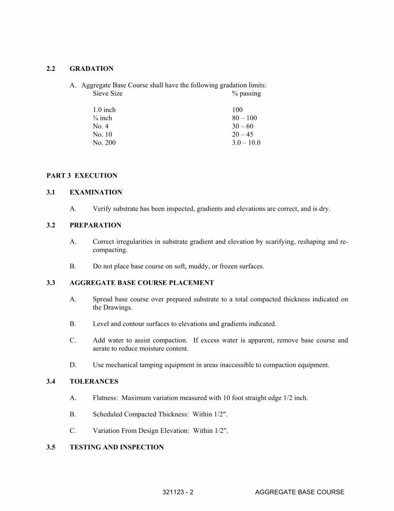
321123 - 2 AGGREGATE BASE COURSE
2.2 GRADATION
A. Aggregate Base Course shall have the following gradation limits:
Sieve Size % passing
1.0 inch 100
¾ inch 80 – 100
No. 4 30 – 60
No. 10 20 – 45
No. 200 3.0 – 10.0
PART 3 EXECUTION
3.1 EXAMINATION
A. Verify substrate has been inspected, gradients and elevations are correct, and is dry.
3.2 PREPARATION
A. Correct irregularities in substrate gradient and elevation by scarifying, reshaping and re-
compacting.
B. Do not place base course on soft, muddy, or frozen surfaces.
3.3 AGGREGATE BASE COURSE PLACEMENT
A. Spread base course over prepared substrate to a total compacted thickness indicated on
the Drawings.
B. Level and contour surfaces to elevations and gradients indicated.
C. Add water to assist compaction. If excess water is apparent, remove base course and
aerate to reduce moisture content.
D. Use mechanical tamping equipment in areas inaccessible to compaction equipment.
3.4 TOLERANCES
A. Flatness: Maximum variation measured with 10 foot straight edge 1/2 inch.
B. Scheduled Compacted Thickness: Within 1/2".
C. Variation From Design Elevation: Within 1/2".
3.5 TESTING AND INSPECTION
321123 - 3 AGGREGATE BASE COURSE
A. General: The Owner shall employ the services of a registered, licensed geotechnical
engineer to observe all controlled earthwork soil testing. The testing laboratory shall pro-
vide continuous on-site observation by experienced personnel during construction of fill
material. The Contractor shall notify the testing laboratory at least two working days in
advance of any field operations of controlled earthwork, or of any resumption of
operations after stoppages.
B. Report of Field Density Tests
1. The geotechnical engineer shall submit, daily, the results of field density tests
required by these specifications.
C. Costs of Tests and Inspection
1. The cost of testing, inspecting and engineering, as specified in this section of the
specifications, shall be borne by the Owner.
D. Compaction required is 95% of laboratory maximum density, not less than one test per
300 square yards.
END OF SECTION
New Mexico State University – New Mexico Ag Mod:Las Cruces, New Mexico
FLEXIBLE PAVING 32 12 00 - 1
SECTION 32 1200 - FLEXIBLE PAVING
PART 1 – GENERAL
1.1 RELATED REQUIREMENTS:
A. Any New Mexico Standard Specifications for Public Works Construction sections referred to or noted on the drawings which pertain to flexible paving design, materials, preparation, and/or execution of this product shall supersede this section. All materials shall be as indicated on Drawings and shall comply with applicable New Mexico Standard Specifications for Public Works Construction regarding source, quality, gradation, and mix design proportioning.
1.2 SUBMITTALS
A. Design Mix: Before any asphalt concrete paving is constructed, submit actual design mix to the Engineer for review and/or approval. Design mix submittal shall follow the format as indicated in the New Mexico Standard Specifications for Public Works Construction, Latest Edition.
B. Material Certificates: Submit materials certificate to onsite independent testing laboratory
which is signed by material producer and Contractor, certifying that materials comply with, or exceed, the requirements herein.
1.3 JOB CONDITIONS
A. Weather Limitations 1. Apply prime and tack coats when ambient temperature is above 40o, and when
temperature has been above 35o for 12 hours immediately prior to application. Do not apply when subgrade is wet or contains excess moisture.
2. Construct asphalt concrete paving when atmospheric temperature is above 40o.
1.4 REFERENCES
A. New Mexico State University Engineering and Construction Design Guidelines, Rev. May 2020.
B. New Mexico State University Construction and Material Specifications, Rev. May 2011.
PART 2 - PRODUCTS 2.1 MATERIALS
A. Provide asphalt-aggregate mixture as recommended by local or state paving authorities to suit project conditions. Use locally available materials and gradations which meet New Mexico
New Mexico State University – New Mexico Ag Mod: Las Cruces, New Mexico
FLEXIBLE PAVING 32 12 00 - 2
Standard Specifications for Public Works Construction, Geotechnical Investigation Recommendations, and exhibit satisfactory record on previous installations.
B. Mineral Filler: Rock or slag dust, hydraulic cement, or other inert material complying with
AASHTO M-17/ASTM D 242, if recommended by applicable New Mexico standards. C. Asphalt Cement: Comply with AASHTO M-226/ASTM D 3381; AC-20, AR-80, viscosity
grade.
D. Tack Coat: Emulsified asphalt; AASHTO M-140/ASTM D 997 or M 208/ASTM D 2397, SS-1h, CSS-1, or Css-1h, diluted with one part water to one part emulsified asphalt.
E. Aggregate Base Course & Asphaltic Concrete: per New Mexico Standard Specifications for
Public Works Construction and Geotechnical Investigation.
2.2 EQUIPMENT Maintain equipment in satisfactory operating condition and correct breakdowns in a manner
that will not delay or be detrimental to progress of paving operations.
PART 3 - EXECUTION
3.1 PREPARATION
A. Remove loose material from compacted base material surface immediately before applying prime coat.
B. Proof roll prepared base material surface to check for unstable areas and areas requiring
additional compaction. C. Do not begin paving work until deficient base material areas have been corrected and are ready
to receive paving.
3.2 APPLICATIONS
A. Prime Coat
1. Apply bituminous prime coat to all base material surfaces where asphalt concrete paving will be constructed.
2. Apply bituminous prime coat in accordance with New Mexico Standard Specifications for Public Works Construction, Section 307.
3. Apply at minimum rate of 0.1 to 0.3 gallons per square yard over compacted base material. Apply to penetrate and seal, but not flood surface.
4. Make necessary precautions to protect adjacent areas from over-spray. 5. Cure and dry as long as necessary to attain penetration and evaporation of volatile
components.
New Mexico State University – New Mexico Ag Mod: Las Cruces, New Mexico
FLEXIBLE PAVING 32 12 00 - 3
B. Tack Coat
1. Apply tack coat to contact surfaces of previously constructed asphalt concrete base courses or Portland cement concrete and surfaces abutting or projecting into asphalt concrete and surfaces abutting or projecting into asphalt concrete pavement.
2. Apply tack coat to asphalt concrete base course or sand asphalt base course. Apply emulsified asphalt tack coat between each lift or layer of full depth asphalt concrete and sand asphalt bases and on surface of all such bases where asphalt concrete paving will be constructed.
3. Apply emulsified asphalt tack coat in accordance with New Mexico Standard Specifications for Public Works Construction, Section 336.
4. Apply at minimum rate of 0.03 to 0.12 gallon per square yard of surface. 5. Allow to dry until at proper condition to receive paving.
3.3 ASPHALTIC CONCRETE PLACEMENT
A. Place asphalt concrete mixture on completed compacted subgrade surface, spread, and strike off. Spread mixture at following minimum temperatures:
1. When ambient temperature is between 40o F and 50o F: 285o F. 2. When ambient temperature is between 50o F and 60o F: 280o F. 3. When ambient temperature is higher than 60o F: 275o F.
B. Place inaccessible and small areas by hand. Place each course to required grade, cross-section, and compacted thickness.
C. Paving Machine Placement: Apply successive lifts of asphalt concrete in transverse directions
with the surface course placed in the direction of surface-water flow. Place in typical strips not less than 10' - 0" wide.
D. Joints: Make joints between old and new pavements, or between successive days' work, to
ensure continuous bond between adjoining work. Construct joints to have same texture, density, and smoothness as other sections of asphalt concrete course. Clean contact surfaces and apply tack coat.
E. Asphalt Concrete Curbs: Construct asphalt curbs over compacted pavement surfaces only
when indicated on Drawings. Apply light tack coat unless pavement surface is still tacky and free from dust. Place curb materials to cross-section indicated by machine or by hand in wood or metal forms. Tamp hand-placed materials and screed to smooth finish. Remove forms as soon as material has cooled.
3.4 ROLLING AND COMPACTION
A. The mixture, after being spread, shall be thoroughly compacted by rolling as soon as it will bear the weight of the rollers without undue displacement. The number, weight, and types of rollers and sequences of rolling operations shall be such that the required density and surface are consistently attained while the mixture is in a workable condition.
New Mexico State University – New Mexico Ag Mod:Las Cruces, New Mexico
FLEXIBLE PAVING 32 12 00 - 4
B. Compact mixture with hot hand tampers or vibrating plate compactors in areas inaccessible to rollers.
C. Breakdown Rolling: Accomplish breakdown or initial rolling immediately following rolling of
joints and outside edge. Check surface after breakdown rolling, and repair displaced areas by loosening and filling, if required, with hot material.
D. Second Rolling: Follow breakdown rolling as soon as possible, while mixture is hot. Continue
second rolling until mixture has been thoroughly compacted. E. Finish Rolling: Perform finish rolling while mixture is still warm enough for removal of roller
marks. Continue rolling until roller marks are eliminated and course has attained maximum density.
F. Patching: Remove and replace paving areas mixed with foreign materials and defective areas.
Cut out such areas and fill with fresh, hot asphalt concrete. Compact by rolling to maximum surface density and smoothness.
G. Protection: After final rolling, do not permit vehicular traffic on pavement until it has cooled
and hardened. Erect barricades to protect paving from traffic until mixture has cooled enough not to become marked.
3.5 FIELD QUALITY CONTROL
A. Independent Testing Laboratory, selected and paid by the Owner, shall be retained to perform construction testing of in-place asphalt concrete courses for compliance with requirements for density. Testing shall be in accordance with ASTM D-2922.
B. Grade Control: Establish and maintain required lines and elevations. C. Surface Smoothness: Testing shall be performed on the finished surface of each asphalt
concrete course for smoothness, using 10' - 0" straightedge applied parallel with, and at right angles to centerline of paved area. The results of these tests shall be made available to the owner upon request. Surfaces will not be acceptable if exceeding following tolerances for smoothness:
Subgrade: 1/2" Wearing Course Surface: 3/16"
D. Check surface areas at intervals necessary to eliminate ponding areas. Remove and replace unacceptable paving as directed by Owner.
END OF SECTION
New Mexico State University – New Mexico Ag Mod:Las Cruces, New Mexico
CONCRETE PAVEMENT, CURB AND SIDEWALKS 32 13 00 - 1
SECTION 32 1300 - CONCRETE PAVEMENT, CURB AND SIDEWALKS
PART 1 - GENERAL
1.1 SUMMARY
A. This Section includes all portland concrete pavement outside the building limits, including but not limited to:
1. Driveways and roadways
2. Parking lots
3. Curbs and gutters
4. Sidewalks
5. Loading Docks and Dolly Pads
B. For concrete located within the building limits: refer to Section 03 3000 – Cast-In- Place Concrete
1.2 REFERENCES
A. American Society of Testing Materials (ASTM)
1. A82 - Standard Specification for Steel Wire, Plain, for Concrete Reinforcement
2. A185 - Standard Specification for Steel Welded Wire Fabric, Plain, for Concrete Reinforcement
3. A615/A615M - Standard Specification for Deformed and Plain Billet-Steel Bars for Concrete Reinforcement
4. C33 - Standard Specification for Concrete Aggregates
5. C94 - Standard Specification for Ready-Mixed Concrete
6. C150 - Standard Specification for Portland cement
7. C171 - Standard Specification for Sheet Materials for Curing Concrete
8. C260 - Standard Specification for Air-Entraining Admixtures for Concrete
9. C309 - Standard Specification for Liquid Membrane-Forming Compounds for Curing Concrete
10. C494/C494M - Standard Specification for Chemical Admixtures for Concrete
New Mexico State University – New Mexico Ag Mod:Las Cruces, New Mexico
CONCRETE PAVEMENT, CURB AND SIDEWALKS 32 13 00 - 2
11. 1C979 - Standard Specification for Pigments for Integrally Colored Concrete
12. 1C1116 - Standard Specification for Fiber-Reinforced Concrete and Shotcrete
13. 1D1751 - Standard Specification for Preformed Expansion Joint Filler for Concrete Paving and Structural Construction (Non-extruding and Resilient Bituminous Types)
14. 1D1752 - Standard Specification for Preformed Sponge Rubber and Cork Expansion Joint Fillers for Concrete Paving and Structural Construction
15. 1D3405 - Standard Specification for Joint Sealants, Hot-Applied, for Concrete and Asphalt Pavements
16. 1D5249 - Standard Specification for Backer Material for Use with Cold- and Hot-Applied Joint Sealants in Portland-Cement Concrete and Asphalt Joints
17. 1D5893 - Standard Specification for Cold Applied, Single Component, Chemically Curing Silicone Joint Sealant for Portland Cement Concrete Pavements
B. American Concrete Institute (ACI)
1. 301R-99 – Specifications for Structural Concrete
2. 304R – Placing and Handling Concrete, etc.
3. 309R-96 – Guide for Consolidating of Concrete
4. 330.1 – Standard Specifications for Plain Concrete Parking Lots
5. 330.2R-17 – Guide for the Design and Construction of Concrete Site Paving for Industrial and Trucking Facilities.
6. 330R-08 – Guide for Design & Construction of Concrete Parking Lots
7. 211R-91 – Standard Practice for Selecting Proportions for Normal, Heavyweight and Mass Concrete
C. American Association of State Highway and Transportation Officials (AASHTO)
1. M182 – Standard Specifications for Burlap Cloth made from Jute for Kenaf
2. M153 – Standard Specifications for Preformed Sponge Rubber and Cork Expansion Joint Filler
D. New Mexico State University Engineering and Construction Design Guidelines, Rev. May 2020.
E. New Mexico State University Construction and Material Specifications, Rev. May 2011.
New Mexico State University – New Mexico Ag Mod:Las Cruces, New Mexico
CONCRETE PAVEMENT, CURB AND SIDEWALKS 32 13 00 - 3
1.3 SUBMITTALS
A. Mix Design: For each concrete mix to be utilized.
B. Material certificates and test reports.
C. The General Contractor and the Subcontractor shall execute the Conformance Submittal(s) at the end of this section.
PART 2 - PRODUCTS
2.1 1STEEL REINFORCEMENT
A. The type of steel reinforcement shall be as shown on the drawings.
1. Plain-Steel Welded Wire Fabric: ASTM A 185, 6inches x 6inches #10 mesh fabricated from steel wire into flat sheets;
2. Reinforcement Bars: ASTM A 615/A 615M, Grade 60, deformed;
3. Plain Steel Wire: ASTM A 82, as drawn; and,
4. Bar Supports: Bolsters, chairs, spacers, and other devices for spacing, supporting, and fastening steel reinforcement. Manufacture bar supports according to CRSI's Manual of Standard Practice.
5. Diamond Dowels: ⅜” x 4 ½” Diamond Dowels by PNA
2.2 CONCRETE MATERIALS
A. Portland Cement: ASTM C 150, Type I, II or III.
B. Aggregate: ASTM C 3 Combined aggregate gradation for concrete pavement and other designated concrete shall be 8% - 18% for large top size aggregates (1½”) or 8% - 22% for smaller top size aggregates (1” or ¾”) retained on each sieve below the top size and above the No. 100 sieve. Concrete pavements shall have a maximum aggregate size of 1½”.
C. Water/Ready Mix Concrete: ASTM C 9
D. Admixtures: Certified by manufacturer to contain not more than 0.1 % water-soluble chloride ions by mass of cement and to be compatible with other admixtures, as follows:
1. Air-Entraining Admixture: ASTM C 260;
2. Water-Reducing Admixture: ASTM C 494, Type A;
3. Water-Reducing and High-Range Admixture: ASTM C 494, Type F;
4. Water-Reducing and Accelerating Admixture: ASTM C 494, Type E; and,
New Mexico State University – New Mexico Ag Mod:Las Cruces, New Mexico
CONCRETE PAVEMENT, CURB AND SIDEWALKS 32 13 00 - 4
5. Water-Reducing and Retarding Admixture: ASTM C 494, Type D.
E. Calcium Chloride: The use of calcium chloride or admixtures containing more than 0.05% chloride ions is prohibited.
F. Curing Materials:
1. Absorptive Cover: AASHTO M 182, Class 2, burlap cloth made from jute or kenaf, weighing approximately 9 oz./sq. yd. dry;
2. Moisture-Retaining Cover: ASTM C 171, polyethylene film or white burlap-polyethylene sheet;
3. Water: Potable;
4. Evaporation Retarder: Waterborne, monomolecular film forming, manufactured for application to fresh concrete;
5. Clear Solvent-Borne Liquid-Membrane-Forming Curing Compound: ASTM C 309, Type 1, Class B;
6. Clear Waterborne Membrane-Forming Curing Compound: ASTM C 309, Type 1, Class B;
7. White Waterborne Membrane-Forming Curing Compound: ASTM C 309, Type 2, Class B.
2.3 CONCRETE MIXES AND MIXING
A. Concrete Mixes: Prepare design mixes, proportioned according to ACI 211R-91 and ACI 304, with the following properties:
1. Compressive Strength (28 Days): 4,000 psi, except as noted on the drawings;
2. Slump Limit: maximum of 5 inches at time of placement for pavement, 2 inch maximum for curb and sidewalk;
3. Air Content: 5% to 8% for pavement, curb and sidewalk.
4. Maximum water-cementitious ratio – 0.48
B. Coloring Agent: When required, add coloring agent to mix according to manufacturer's written instructions.
1. Expansion- and Isolation-Joint-Filler Strips: ASTM D 1751, asphalt-saturated cellulosic fiber, or ASTM D 1752, cork or self-expanding cork; and,
2. Coloring Agent: ASTM C 979, synthetic mineral-oxide pigments or colored water-reducing admixtures; color stable, nonfading, and resistant to lime and other alkalis.
C. Ready-Mixed Concrete: Comply with requirements and with ASTM C 94 and ASTM C 111
New Mexico State University – New Mexico Ag Mod:Las Cruces, New Mexico
CONCRETE PAVEMENT, CURB AND SIDEWALKS 32 13 00 - 5
D. Project-Site Mixing: On-site mixing must be approved by the Owner. Comply with requirements and measure, batch, and mix concrete materials and concrete according to ASTM C 9 Mix concrete materials in appropriate drum-type batch machine mixer.
2.4 JOINTS, FILLERS, AND SEALANTS
A. Joint-Sealant Backer Materials: ASTM D5249, Non-Staining, compatible with joint substrates, sealants, primers, and other joint fillers; and approved for applications indicated by joint sealant manufacturer based on field experience and laboratory testing.
B. Joint Sealant: Non-priming, pourable self-leveling silicone sealant for concrete and asphalt.
1. Cold-Applied Joint Sealant ASTM D5893, self-leveling silicone sealant. Crafco, Inc. “Roadwaver Silicone-SL”; Dow Corning “888, or 890-SL”; Sonneborn “Sonomeric 1 Sealant”; Tremco “Vulkem 45”; and,
2. Hot-Applied Joint Sealant: ASTM D3405, Polymeric sealant. Crafco Inc. “ROADSAVER 22”; W.R. Meadows, Inc. “SEALTIGHT HI-SPEC”.
C. Joint Fillers: Resilient pre-molded bituminous impregnated fiberboard units complying with ASTM D 1751, asphalt-saturated cellulosic fiber, ASSHTO M 153, Type I: or ASTM D 1752, cork or self-expanding cork.
D. Exterior Concrete Sealant: Sonneborn “Kure-N-Seal 30” exterior acrylic sealer, or Euclid “Super Rez-Seal”.
PART 3 - EXECUTION
3.1 INSTALLATION
A. Surface Preparation: Proof roll prepared subbase, per Section 31 00 00 and the geotechnical report- Earthwork and remove loose material from surface.
B. Forms: Set, brace, and secure edge forms, bulkheads, and intermediate screed guides for pavement to required lines, grades, and elevations, per Section 02010, Project Survey, and Layout.
1. Maintain sufficient quantity of forms to allow continuance of work so that forms remain in place a minimum of 24 hours after concrete placement;
2. Forms shall be cleaned and casted with form release agent thoroughly after each use and before concrete is placed; and,
3. Flexible or curved forms shall be used on curves. Forms shall be of full depth of the concrete and of a strength when staked, sufficient to resist the presence of the concrete and the loads resulting from the finish operations without springing, setting or losing their shape.
New Mexico State University – New Mexico Ag Mod:Las Cruces, New Mexico
CONCRETE PAVEMENT, CURB AND SIDEWALKS 32 13 00 - 6
C. Reinforcement: Accurately position and support reinforcement, and secure against displacement. Set wire ties with ends directly into concrete.
1. Install welded wire fabric in lengths as long as practicable; lap at least one full mesh, and lace splices with wire; and,
2. Support reinforcing steel on wire chairs to ensure that wire stays mid-depth of sidewalk section during concrete pour.
D. Joints: Construct pre-molded expansion and contraction joints, tied construction joints, control joints, thickened edge expansion joints, isolation joints, and construction joints, straight with face perpendicular to concrete surface. Construct transverse joints perpendicular to centerline unless otherwise detailed.
1. Expansion joints and Contraction joints: Pre-molded as indicated on the drawings;
a. Provide joint filler for the entire depth of the slab section and not less than 1inch below finished surface so as to allow for joint sealer.
b. Provide thickened edge expansion joint as indicated on the drawings.
c. Provide 1/2-inch contraction joints for curb and gutter at 5 feet on center.
d. Provide 1/2-inch expansion joints for curb and gutter and sidewalk at 30 feet on center.
2. Tied construction joints: As indicated on drawings;
3. Control joints: Depth shall be equal to ¼ of the concrete thickness or 1 inch, whichever is deeper.
a. For sidewalks, control joint spacing shall be equal to the sidewalk width.
b. For concrete pavement, control joint spacing shall be placed as shown on the drawings, no greater than 30 times the slab thickness on center either way;
c. Form tooled joints in fresh concrete by grooving top portion with recommended tool and finishing edges with jointer.
d. Form sawed joints using powered saws equipped with shatterproof abrasive or diamond-rimmed blades. Cut joints into hardened concrete within 24 hours of the concrete placement and as soon as surface will not be torn, abraded, or otherwise damaged by cutting action.
4. Construction Joints: Place construction joints at end of placements and at locations where placement operations are stopped for period of more than ½ hour, except where such placements terminate at expansion joints. Provide ⅜” x 4½” Diamond Dowels by PNA at 24” on center or as shown on the drawings;
New Mexico State University – New Mexico Ag Mod:Las Cruces, New Mexico
CONCRETE PAVEMENT, CURB AND SIDEWALKS 32 13 00 - 7
5. Isolation Joints: Locate isolation joints as indicated on the drawings. Provide pre-molded joint filler for catch basins, manholes, inlets, structures, walks, light pole bases and other fixed objects;
6. Joint Fillers: Extend joint fillers full-width and depth of joint, and not less than ½inch or more than 1 inch below finished surface where joint sealer is indicated. Furnish joint fillers in one-piece lengths for full width being placed, wherever possible. Where more than one length is required, lace or clip joint filler sections together; and,
7. Joint Sealants: All joints shall be sealed with approved exterior pavement joint sealants and shall be installed per manufacturer’s recommendations.
E. Concrete Placement: Comply with recommendations in ACI 304R for measuring, mixing, transporting, and placing concrete. Place concrete in a continuous operation within planned joints or sections.
1. Moisten subbase to provide a uniform dampened condition at time concrete is placed;
2. Consolidate concrete by mechanical vibrating equipment supplemented by hand-spading, rodding, or tamping according to recommendations in ACI 309R;
3. Screed and initial-float concrete surfaces with darby or bull float before excess moisture or bleed water appears on the surface;
4. Protect concrete from cold or hot weather during mixing, placing, and curing; and,
5. All concrete walks and aprons shall be a minimum of 4 inches thick as shown on the drawings, with a turned down edge as detailed.
F. Evaporation Retarder: Apply to concrete surfaces if hot, dry, or windy conditions exist. Apply according to manufacturer's written instructions after placing, screeding, and bull floating or darbying concrete, but before float finishing.
G. Pavement Tolerances: Comply with tolerances in ACI 330.1, Specification for Plain Concrete Parking Lots.
3.2 FINISHES AND CURING
A. All exterior concrete shall receive a medium broom finish.
B. Curing: Begin curing after finishing concrete, but not before free water has disappeared from concrete surface. Cure concrete by one or a combination of the following methods: 1. Moisture cure concrete by water, continuous fog spray, continuously wet absorptive
cover, or by moisture-retaining-cover curing. Keep surfaces continuously moist for not less than 7 days; and,
2. Curing Compound: Apply uniformly in continuous operation by power spray or roller according to manufacturer's written instructions. Recoat areas subjected to heavy rainfall within three hours after initial application. Maintain continuity of coating and repair damage during curing period.
New Mexico State University – New Mexico Ag Mod:Las Cruces, New Mexico
CONCRETE PAVEMENT, CURB AND SIDEWALKS 32 13 00 - 8
C. All exterior concrete surfaces shall receive one coat of exterior sealer.
3.3 REPAIRS AND PROTECTION
A. Remove and replace concrete pavement that is broken, damaged, or defective, or does not meet requirements in this Section.
B. Protect concrete from damage. Provide adequate traffic control to prevent traffic from pavement for at least 14 days after placement.
C. Maintain concrete pavement free of stains, discoloration, dirt, and other foreign material. Sweep concrete pavement not more than 2 days before date scheduled for substantial completion inspections.
3.4 QUALITY ASSURANCE
A. Manufacturer Qualifications: Manufacturer of ready mixed concrete products complying with ASTM C 94 requirements for production facilities and equipment.
B. ACI Publications: Comply with ACI 301R-99 and ACI330R-92, unless modified by the requirements of the Contract Documents.
C. The owner shall provide and pay for testing services. A slump test and air test shall be performed for each load delivered. Four standard test cylinders shall be taken for each 55 cubic yards of concrete or each day’s pour, whichever is more frequent. Two cylinders shall be broken at 7 days and two cylinders shall be broken at 28 days.
END OF SECTION
328400 - 1 IRRIGATION SYSTEM
SECTION 328400 - LANDSCAPE IRRIGATION SYSTEM
PART 1 - GENERAL
1.1 DESCRIPTION OF WORK
A. The work consists of installing a complete underground irrigation system as shown on the
Drawings and as specified hereafter. The Contractor shall furnish all labor, equipment,
materials and permits necessary for the completion of the system, unless otherwise
specified to be furnished by others. Unless otherwise specified or indicated on the
Drawings, the construction of the irrigation system shall include the furnishing, installing
and testing of all components pertinent to the system. The Contractor shall perform all
trenching, excavating, boring, backfilling, compacting, concrete work, electrical work,
welding, and any other work necessary for the completion of the irrigation system.
1.2 SITE INVESTIGATION
A. The Contractor shall examine related work and surfaces before starting the work of this
section. The Contractor shall report to the Owner’s Representative, in writing, conditions
which will prevent the proper execution of irrigation installation. Deviations from
Drawings and Specifications shall be executed only with the express permission of the
Owner’s Representative and at no cost to the Owner. If inadequacies or inappropriate
design are found on the Drawings, they shall be promptly brought to the attention of the
Owner’s Representative in writing before proceeding with installation of the system.
1.3 CODES, RULES AND SAFETY ORDERS
A. All work and materials shall be in full accordance with the latest local rules and
regulations of safety.
1.4 PROTECTION
A. The Contractor shall furnish and maintain all warning signs, shoring, barricades, red
lanterns, and other protection devices, as required by the Safety Orders of the Division of
Industrial Safety and local ordinances.
1.5 DEVIATIONS OF LAYOUT
A. Reasonable changes in the location of piping, valves or other irrigation components
shown on the Drawings will be considered prior to installation. Deviations from
specified locations must be approved by the Owner’s Representative prior to installation.
Any changes in location of irrigation components shall be effected at no cost to the
Owner.
1.6 COORDINATION
A. The Contractor shall coordinate and cooperate with other contractors on site to ensure
rapid and efficient completion of all contracted work.
1.7 SUBMITTALS
328400 - 2 IRRIGATION SYSTEM
A. The Contractor shall prepare submittals providing manufacturer’s specifications and
product information on the following components:
Manual and automatic valves Heads and emitters Enclosures
Backflow preventer Valve boxes Drains
24 Volt wire Wire splicing materials Controller
Piping and tubing PVC fittings Filters
Joint materials Detectable line marking tape Grounding wire
PVC primer and cement Threaded joint sealant or tape Grounding rods
Quick couplers Swing joints
B. Each set of submittals shall be bound or provided electronically in PDF format, and shall
be clearly labeled with the project name and date.
C. The Contractor shall not proceed with the irrigation system work until receiving approval
of the irrigation submittals from the Owner’s Representative.
1.8 AS-BUILTS
A. The Contractor shall provide and keep up to date a complete set of “As-Builts” which
shall be corrected daily to show all changes in the location of heads, controllers,
backflow preventers, valves, drains, meters, points of connection, pull boxes and wire
splice boxes, pipe and wire routing and other changes that may have been made from the
original Drawings and Specifications. All gate valves, manual drains, wire splice and
automatic and manual valve locations shall be shown with actual measurements to
reference points so they may be easily located in the field.
B. At the time of final acceptance, the Contractor shall furnish one electronic copy (on CD)
and one paper copy of “As-Builts” prepared by a qualified draftsperson in AutoCAD
format, showing the entire completed system as actually installed. This is the
responsibility of the Contractor and shall not be construed to be the responsibility of any
other party. This drawing shall be accurate and to scale. The symbols for valves, heads,
and piping and other components shall be the same as originally shown on the Drawings.
The legend shall be modified to designate any “record” changes. This “As-Built” shall
be drawn on a project base sheet provided by the Owner’s Representative. The final
drawings shall be dated and clearly labeled “AS-BUILT”.
1.9 CONTROLLER CHART
A. The Contractor shall provide two controller charts for each controller. Chart shall show
the area covered by each automatic valve station on the controller with a different color
used to show the area of coverage for each valve. Chart shall be a reduced drawing of the
actual “As-Built” system. The size of the chart shall be the maximum size that the
controller door will allow. If controller sequence is not legible when the drawing is
reduced, drawing shall be enlarged to a size that is readable.
B. When completed and approved, chart shall be laminated with minimum 20 mils thick
sheets. Chart shall be completed and approved prior to final observation and acceptance
328400 - 3 IRRIGATION SYSTEM
of the irrigation system. Contractor shall install one chart in each controller enclosure and
shall provide one chart for each controller to the Owner’s Representative.
PART 2 - PRODUCTS
2.1 MATERIALS
A. All materials shall be new and without flaws or defects of any type and shall be the best
of their class and kind. All materials shall have a minimum warranty of one year against
material defects or defective workmanship.
B. All material shall be the brands and types noted on the Drawings or as specified herein,
or approved equal (refer to Section 6.7 of the New Mexico Standard Specifications for
Public Works Construction, 1979 Edition).
C. The irrigation system was designed around equipment manufactured by specific
companies as a standard. Approved equal equipment by other manufacturers may be
used only with the approval of the Owner’s Representative. Request for approval of non-
specified materials shall be submitted to the Owner’s Representative a minimum of seven
(7) days prior to the opening of bids. Submission of irrigation sprinkler heads for
approval as equal shall only be considered if submitted heads match the precipitation rate,
gallons per minute and spacing of specified sprinkler heads.
D. Irrigation components designated for use with recycled water shall be marked in
accordance with the Uniform Plumbing Code.
2.3 PLASTIC PIPE AND FITTINGS
A. Plastic Pipe: Piping with a diameter of two inches (2”) or less shall be Schedule 40 PVC
and shall conform to ASTM D 1785. Piping with a diameter of two and one-half inches
(2-1/2”) or greater shall be Class 200 “O” ring gasket pipe, SDR 21 and shall conform to
ASTM D 2241. All PVC pipe shall be continuously marked with identification of the
manufacturer, type, class, and size, and shall be free of holes, foreign material, blisters,
wrinkles, dents or sunburn.
B. PVC Fittings: Fittings on PVC lines shall be Schedule 40 PVC, Type 1, Cell
Classification 12454 and shall comply with ASTM D 2466.
C. Threaded Nipples: All threaded PVC nipples shall be Schedule 80 molded PVC pipe.
All galvanized nipples shall be Schedule 40 galvanized steel pipe.
2.4 VALVES AND VALVE BOXES
A. Valves: Valves for use in electrically controlled automatic control systems shall be
diaphragm actuated and hydraulically operated solenoid valves as specified on the
Drawings.
B. Isolation valves shall be as specified on the Drawings.
C. Valve Boxes: Valve boxes shall be as noted on the Drawings. Valve box colors shall be
328400 - 4 IRRIGATION SYSTEM
as follows:
1. Green: Turf areas (potable water)
2. Tan: Gravel mulch areas (potable water)
3. Purple: Reclaimed water
2.5 HEADS AND EMITTERS
A. Heads and emitters shall be as specified on the Drawings.
2.6 CONTROLLER
A. Controller shall be as specified on the Drawings.
2.7 BACKFLOW PREVENTER AND HEATED ENCLOSURE
A. The backflow prevention device and heated enclosure shall be as specified on the
Drawings.
2.8 PRIMER, CEMENT AND THREADED JOINT SEALANT
A. Primer shall conform to ASTM F 656 and meet NSF. Cement shall be low VOC, NSF
approved, and meet ASTM D 2564. Cement and primer shall be IPS Weld-On depending
on size and schedule of pipe and fittings as follows:
Schedule 40 PVC Pipe and Fittings up to 6” Dia.: P-68 Primer and 705 Cement
Schedule 80 PVC Pipe and Fittings up to 4” Dia.: P-70 Primer and 705 Cement
Schedule 80 PVC Pipe and Fittings larger than 4” Dia.: P-70 Primer and 711 Cement
B. All threaded connections between metal to metal, PVC to metal, and PVC to PVC shall
be made using Spears Blue 75 thread sealant or Polytetrafluoroethylene (PTFE) thread
seal tape. PTFE thread seal tape shall comply with MIL-T-27730A Specifications shall
have a minimum thickness of 3.5 mils and shall be 99% pure PTFE. Thread sealing
compound shall not be used on threaded connections between sprinkler and nipple or
bubbler and nipple. Thread sealant or PTFE tape shall be used in accordance with
manufacturer’s installation instructions.
C. All “O” ring gasket and pipe spigot ends shall be lubricated using the lubricant
recommended or supplied by the pipe manufacturer. If the pipe manufacturer does not
provide a lubricant for the pipe, use IPS Weld-on EZ Flush pipe lubricant, NSF approved.
2.9 WIRE
A. Wire for the 120 volt wiring shall be solid copper (or stranded copper in larger wire
sizes), underground feeder for direct burial and PVC insulated. Size of wire shall be #12
AWG.
B. Wire for the 24 volt wiring shall be solid copper wire, PVC insulated, UL approved
underground feeder wire for direct burial in ground. Common wires shall be #12, white,
except as noted on Drawings. The control wires shall be #14 of any color other than
328400 - 5 IRRIGATION SYSTEM
white unless otherwise indicated on Drawings. The wire shall be supplied in either 500’
or 2,500’ rolls.
C. Wire Splicing Materials: All wire splices shall be made water-tight using 3M DBR/Y
direct bury splice kit or approved equal.
D. Grounding wire, ground rods and wire clamps for controllers shall be as specified by the
controller manufacturer.
E. Control wires shall be marked with the associated valve number with E-Z Coder WDR or
equal wire marking tape at each valve, at the controller and at wire splices.
2.10 DETECTABLE LINE MARKING TAPE
A. Detectable line marking tape for irrigation main and lateral lines shall be manufactured
by T.A. Christy Enterprises or approved equal and shall consist of a minimum 5.0 mil
(0.0050”) overall thickness; five-ply composition; ultra high molecular weight; 100%
virgin polyethylene; acid, alkaline, and corrosion resistant.
B. The tape width shall be a minimum of 6”.
C. Elongation properties shall be in accordance with ASTM D882-80A and shall be less
than 150% at break.
D. Tensile strength shall be in accordance with ASTM D882-80A and shall be not less than
7800 PSI.
E. The tape shall have a minimum 20 gauge (0.0020”) solid aluminum foil core, adhered to
a 2.55 mil (0.00255”) polyethylene backing.
F. Tape color and legend combination shall be in accordance with APWA requirements.
For irrigation lines with potable water supply, the color shall be blue and the legend shall
read “CAUTION: IRRIGATION LINE BURIED BELOW”. For irrigation lines with
non-potable water supply, the color shall be purple and the legend shall read
“CAUTION: RECYCLED/RECLAIMED WATER LINE BURIED BELOW”.
2.11 OTHER MISCELLANEOUS FITTINGS AND MATERIALS
A. All other miscellaneous fittings and materials shall be as specified on the Drawings.
PART 3 - EXECUTION
3.1 GENERAL
A. This section includes installation specifications for all items installed as a part of the
irrigation system. Certain construction procedures or minor equipment installation
procedures that are necessary for the proper installation of the system may have been
omitted from these specifications. In any case, Contractor shall install all materials and
equipment in a neat and workmanlike manner according to manufacturer's
recommendations and specifications, local and state codes, as shown on the Drawings
328400 - 6 IRRIGATION SYSTEM
and as specified herein.
3.2 PRODUCT HANDLING
A. The Contractor shall be responsible for correct procedures in loading, unloading, staking,
transporting and handling all materials to be used in the system. The Contractor shall
avoid rough handling which could affect the useful life of equipment. Pipe shall be
handled in accordance with the manufacturer's recommendations on loading, unloading
and storage.
3.3 POINT OF CONNECTION
A. Existing water main line locations shown on the Drawings are schematic. It shall be the
Contractor’s responsibility to pot hole and field check to determine actual locations as an
incidental requisite to the construction contract.
B. The proposed controller location indicated on the Drawings is approximate. Actual
location of the controller shall be determined by Owner’s Representative in the field.
C. Where connections to existing pipe or stub out is required, the Contractor shall make
necessary adjustments should pipe or stub out not be located exactly as shown, at no
additional cost to the Owner.
3.4 STATIC PRESSURE TEST
A. The design pressure of the irrigation system is shown on the Drawings. Prior to start of
construction of the irrigation system, the Contractor shall, in the presence of the Owner’s
Representative, provide a gauged test of available static pressure at the point of
connection. In the event that the actual static pressure is significantly different (plus or
minus 10 psi) than the design static pressure, the Contractor shall not proceed with the
work until receiving written direction from the Owner’s Representative.
3.5 EXCAVATION AND TRENCHING
A. The Contractor shall stake the location of each run of pipe and all sprinkler heads and
valves prior to trenching. Each run of the system shall be approved by the Owner’s
Representative prior to installation.
B. Excavation and trenching for pipe lines shall be a true and straight line with the trench
banks as nearly vertical as practical. The width of the trenches shall not be greater than
necessary to permit proper joining, tamping, backfilling, bedding or any other installation
procedures that may be necessary. Trench widths shall be wide enough to provide a
minimum horizontal and vertical separation of 4" between pipes in the same trench.
C. In areas where trees are present, trench lines shall be adjusted on the site to eliminate any
damage to tree roots.
D. Trench depths shall be sufficient to provide the specified pipe cover as described
elsewhere in these Specifications or as noted on the Drawings. In rocky areas the trench
depth and width shall be increased as needed to provide for a minimum of 6"of pipe
328400 - 7 IRRIGATION SYSTEM
bedding at bottom and sides of pipe.
E. Depth of Bury: Minimum cover over mainline and lateral piping shall be as noted on the
Drawings.
3.6 PIPE AND FITTINGS INSTALLATION
A. Installation of plastic pipe and fittings shall be in accordance with ASTM D 2774, the
manufacturer’s recommendations and the procedures described in these Specifications.
B. Caution shall be exercised by the Contractor in handling, loading, unloading, and storing
of PVC pipe and fittings. All PVC pipe shall be stored and transported in a vehicle with
a bed long enough to allow the pipe to lie flat without subjecting it to undue bending or
concentrated external load at any point. Pipe shall be protected from damage by
exposure to sunlight. Any section of pipe that has been dented or damaged or in any
other way found to be defective, either before or after laying shall be replaced with sound
pipe at no cost to the Owner.
C. Before installation, the inside of the pipe shall be cleaned of all dirt and foreign matter
and shall be kept in a clean condition during and after laying of pipe. When work is not
in progress, open ends of pipe and fittings shall be secured closed so that no trench water,
earth or other foreign substances will enter the pipe or fittings. Where pipe ends are left
for future expansion or connections, they shall be valved and capped as directed on the
Drawings.
D. All PVC pipe and fittings shall be assembled to permit the pipe or fittings to be jointed at
the true parallel position of the fittings. Placement of pipe which cause excessive
bending and stress on pipe and fittings will not be permitted. No excess piping or fittings
shall be permitted in the installation of the system, as this may increase pressure loss or
potential for blockage.
E. Before installing the pipe, all rocks over 1 inch diameter, rubbish and debris shall be
removed from the trenches. If the adjacent soil is rocky, the trenches shall be bedded and
filled with clean dirt or sand to provide a minimum of 6” clearance between the pipe and
the native soil. Material used for pipe bedding and trench filling shall be approved by the
Owner’s Representative. The full length of each section of the pipe shall rest solidly
upon the pipe bed, with recesses excavated to accommodate bells, joints and couplings.
F. Pipe shall not be laid in water or when trench or weather conditions are unsuitable for the
work. Any water which may be encountered or may accumulate in the trenches or
excavation shall be pumped out or otherwise removed as necessary to keep the bottom of
the trench or excavation free and clear of water during the progress of the work. Pipe
shall not be laid when the temperature is 32 degrees F or below.
G. PVC pipe will expand or contract at the rate of +/- 3/8” per 100’ per 10 degrees F change
of temperature. Therefore, the pipe shall be installed in a manner to provide for
expansion and contraction as recommended by the manufacturer.
H. The minimum horizontal and vertical clearance between lines in the same trench shall be
4".
328400 - 8 IRRIGATION SYSTEM
I. After all piping, risers, valves, thrust blocks, etc., have been installed and partially
backfilled as specified in other parts of these Specifications, the control valve shall be
opened and a full head of water used to flush out the system. Caution shall be observed
to provide for release of any entrapped air in the system. After the system is thoroughly
flushed, risers shall be capped and the system pressure tested in accordance with the
testing section of these Specifications. At the conclusion of the pressure test, the heads
shall be installed and the backfill operation completed.
3.7 SOLVENT WELDING PROCEDURE
A. All solvent weld joints shall be made in accordance with the solvent manufacturer’s
recommendations and ASTM D 2855.
B. PVC plastic pipe shall be squarely cut utilizing a miter box mounted hacksaw or PVC
specialty saw with a blade of 18 or 24 teeth per inch.
C. Interior and exterior burrs shall be removed and the exterior shall be beveled to produce a
10-15 degree bevel.
D. Thoroughly clean the mating pipe end and the fitting socket with a clean, dry cloth.
E. Using a properly sized applicator (approximately ½ the diameter of the pipe), apply a
light coating of primer to the inside of the fitting socket, then apply a thin coat to the
outside of the pipe end. Apply a second, light coat of primer to the inside of the fitting
socket taking care to avoid puddling of primer in fitting.
F. Apply a uniform coat of cement to the outside of the pipe end with a properly sized
applicator (approximately ½ the diameter of the pipe).
G. In like manner, apply a thin coating of cement to the inside of the fitting socket.
H. Re-apply a light coat of cement to the outside of the pipe end and quickly insert it into the
fitting to the full depth of the fitting socket, while rotating the pipe or fitting
approximately ¼ turn to ensure even distribution of cement.
I. Hold in position for approximately 30 seconds.
J. Wipe off any excess solvent cement that forms as a bead around the outer shoulder.
K. Contractor shall not use an excessive amount of solvent cement that could cause burrs or
obstructions to form on the inside of the pipe joint.
L. Solvent weld joints shall be allowed to cure for minimum 24 hours before pressure is
applied to the system.
3.8 BACKFILLING
A. Upon completion of a particular section of the irrigation system, and after sufficient time
has elapsed for the curing of solvent weld joints, partial backfilling shall begin, leaving
328400 - 9 IRRIGATION SYSTEM
all joints, risers and connections exposed for visual inspection during the hydrostatic
testing. Only upon successful completion of the hydrostatic test shall the backfill
operation be completed for any one particular section.
B. All backfill material shall be subject to approval by the Owner’s Representative. Backfill
material shall be free from rock, large stones, brush, sod, frozen material or other
unsuitable substances that may damage pipe or compromise compaction during the
backfilling operations.
C. In the event that the material from the excavation or trenching is found to be unsuitable
for use in backfill by the Owner’s Representative, it shall be removed from the site and
properly disposed of by the Contractor at his own expense. The Contractor shall then, at
no cost to the Owner, arrange for, purchase, and furnish suitable backfill material
consisting of earth, loam, sandy clay, sand or other approved materials free of large clods
of earth or sharp stones and capable of attaining the same relative density of the
surrounding ground.
D. In rocky areas, the trench depth shall be 6” below the normal trench depth to allow for 6”
of suitable backfill as padding for the pipe. In like manner, there shall be minimum 6” of
suitable backfill on all sides of the pipe as padding against rock in the wall of the trench.
E. All mainline and lateral piping shall have detectable line marking tape installed in the
trench six (6”) inches above the pipe. After pipe is placed in trench and the first 6" layer
of backfill is placed and compacted, the detectable marking tape shall be placed
continuously in all trenches prior to completion of backfill operations.
F. Backfill shall be placed in horizontal layers not exceeding 6” in depth and shall be
thoroughly tamped, or water compacted to near original density or so that no settling will
result. Backfill shall be placed to the original ground level. If settlement of trenches
occurs within one (1) year from date of completion, it shall be the Contractor's
responsibility to refill trenches and re-seed, re-sod or re-install landscape mulch in the
repaired areas.
3.9 SADDLE TAPS
A. No saddle taps shall be permitted unless approved by the Owner’s Representative.
3.10 THRUST BLOCKS
A. Concrete thrust blocks shall be provided where necessary to resist system pressure,
including at all direction changes, size changes, valves and terminations or at any other
points of the system that will result in an unbalanced thrust line for equipment 2-1/2” and
larger and as indicated on the Drawings. Thrust blocks shall not obstruct the outlets of
fittings which are intended for future connections. Thrust blocks shall be poured against
undisturbed earth and in accordance with the Drawings.
3.11 SLEEVED CROSSING
A. Unless otherwise noted on the Drawings, all piping installed under sidewalks, roadways,
parking lots, etc., shall be sleeved in a Class 200 PVC pipe two (2) sizes larger than the
328400 - 10 IRRIGATION SYSTEM
pipe to be sleeved. Wire shall be placed in a separate sleeve from that of the pipe
crossing and shall be Class 200 PVC minimum 2” size, or larger as required to
accommodate the quantity of wire to be sleeved. Ends of sleeves shall be sealed with
duct tape after installation of wire or piping.
3.12 HEAD INSTALLATION (ROTORS AND POP UPS)
A. Heads shall be of the type and make specified and shall be installed as shown on the
Drawings. Heads shall be installed with a 4" space between the edge of the head and
curbs, walks, walls, driveways, building walls, etc. Heads shall be installed in the
vertical position and backfilled and compacted to 80% modified Proctor.
B. Head spacing shall not exceed the spacing shown on the Drawings and shall be in the
location and configuration as shown on the Drawings. Contractor shall verify turf area
dimension while staking head location. Heads shall be spaced to achieve uniform
coverage.
C. After all piping and risers are in place and connected and before installation of the heads,
all control valves for a given section shall be fully opened and a full head of water shall
be used to flush out the system. If water pressure without the heads installed is not
sufficient to provide adequate water flow from end risers, the Contractor shall cap off
enough heads closest to the water source to provide adequate flushing of the end riser
assemblies.
3.13 CONTROLLER INSTALLATION
A. The controller location is indicated on the Drawings. The Contractor shall familiarize
himself with the requirements of making the power connections at the locations noted
(120 volt supply to the controller) and shall include in his price for the irrigation system,
the cost to complete this portion of the work.
B. The controller shall be mounted and wired according to the manufacturer's recommended
procedures and as specified herein and on the Drawings.
C. Unless otherwise indicated in the Drawings, the Contractor shall direct-wire the 120 volt
power supply to the controller.
D. Remote control valves shall be connected to controller in the numerical sequences as
shown on the Drawings or as directed by the Owner’s Representative.
E. Controllers shall be grounded as specified by the manufacturer and as indicated on the
Drawings.
3.14 AUTOMATIC CONTROL VALVE INSTALLATION
A. Automatic control valves shall be of the type and size indicated on the Drawings.
Installation shall be according to these Specifications, the Drawings and the
manufacturer's recommendations.
B. The valve boxes shall be of the size and type as shown on the Drawings.
328400 - 11 IRRIGATION SYSTEM
C. Valve wire splices shall be waterproofed using 3M DBR/Y direct bury splice kit or
approved equal. The Contractor shall provide a 36" wire expansion coil to facilitate
raising splices to ground level without cutting wires.
3.15 24 VOLT CONTROL VALVE WIRING
A. Wire installation procedures shall conform to local codes.
B. The Contractor shall install the 24 volt control valve wiring in the same trench as the
irrigation mainline. All wires shall be laid below the pipe. In no case shall the wire be
laid on top of the pipe. The wires shall be laid loose in the trench and taped together at
10'-0" intervals. When trenches used for piping are not appropriate for routing wire,
Contractor shall install wire in a separate trench at 18" bury depth.
C. Wire splices, other than at valve box locations, shall be kept to a minimum and if needed
shall be made only at common splice points and placed in a wire splice box, Applied
Engineering 9” round valve box with flush cover or equal. Wire splices shall be
waterproofed using 3M DBR/Y direct bury splice kit or approved equal.
D. At control wire splices, the Contractor shall provide a 36" wire expansion coil to facilitate
raising splices to ground level without cutting wires.
E. Continual wire shall be one color and in no case shall wires of different colors be spliced
together.
F. All 24 volt wiring shall be installed in PVC conduit when inside a building. All 24 volt
wiring installed on exterior building walls shall be installed in metal conduit.
3.16 120 VOLT CONTROLLER POWER WIRING
A. The Contractor shall familiarize himself with the work required to complete this portion
of the installation. All 120 volt wiring shall be installed in accordance with local
electrical codes. The 120 volt service shall consist of one (1) black and one (1) white
wire. The neutral wire shall be bonded.
B. The 120 volt power shall be supplied to the controller location and the backflow
preventer location by a licensed electrician.
3.17 TESTING
A. Upon completion of the irrigation system's mainline, the entire mainline shall be tested
with the Owner’s Representative present, for a one hour period at 100 psi, unless
otherwise noted. Prior to testing, the mainline shall be partially backfilled, leaving all
joints and connections exposed for visual inspection. All dirt shall be flushed from the
system and the line filled with water to remove air. The mainline shall be brought to
static pressure. A pressure gauge and temporary valve shall be installed at the end of the
mainline to permit air pressure to be applied to the main. A pressure of 100 psi shall be
retained for a one hour period. Any leaks occurring during the one hour pressure test
shall be repaired and the system retested until the system passes the test.
328400 - 12 IRRIGATION SYSTEM
B. Upon completion of the lateral piping sections, each lateral system shall be pressure
tested, with the Owner’s Representative present for one hour at 100 psi. On systems using
flex nipples or swing joints, the lateral system shall be tested prior to installation of the
flex nipples or swing joints. Prior to testing, the lateral lines shall be partially backfilled
leaving all joints and connections exposed for visual inspection. All air and dirt shall be
flushed from the system and all open fittings shall be capped. The testing procedure shall
be the same as used for the main line. Any leaks occurring during the hydrostatic test
shall be repaired and the system retested until the system passes the test. If after one hour
100 psi pressure has been retained, the heads shall be installed, and the backfill operation
completed.
C. The Contractor shall be responsible for payment of construction observations for
retesting of any lines or system components that fail initial pressure or performance test.
Costs shall include the time of the observer at the observer’s standard rate, travel time
and travel expenses.
3.18 ADJUSTING OF SYSTEM
A. After completion of testing and installation, the Contractor shall adjust all valves for the
proper operating pressure and adjust all heads for uniform coverage and even flow.
Contractor shall wire the controller to have station numbers correspond with valve
numbers indicated on the Drawings or as directed by the Owner’s Representative. The
valve number shall be indicated on the controller panel for each station. Contractor shall
program the controller to provide optimum system performance.
3.20 CLEAN UP
A. The Contractor shall continuously keep a neat and orderly area in which he is installing
the system. Disposal of rubbish and waste material resulting from the installation shall
be continual. Upon completion of the system, the Contractor shall remove from the
Owner's property at his own expense, all temporary structures, rubbish, waste material,
tools and equipment resulting from or used in the installation of the system.
3.21 PROTECTION OF EXISTING UTILITIES
A. The Contractor shall be responsible for locating all existing cables, conduits, piping, and
any other utilities or structures that may be encountered either above or below ground.
All necessary precautions shall be taken by the Contractor to prevent any damage to the
existing utilities and improvements. In the event that such damage should occur from his
operations, the Contractor shall repair or replace damaged utilities to their original
condition at no expense to the Owner.
3.22 ROCK
A. If the Contractor encounters rock or other unfavorable trenching conditions, no additional
compensation will be paid. When material from the excavation or trenching is unsuitable
for use as backfill, additional backfill material suitable for this purpose shall be brought
in at the expense of the Contractor. It shall be the Contractor's responsibility to remove
and dispose of all unsuitable materials removed from the trench that cannot be used in the
328400 - 13 IRRIGATION SYSTEM
backfill operation.
3.23 FINAL ACCEPTANCE
A. When the Contractor is satisfied that the system is operating properly, that it is balanced
and adjusted and that all work and clean-up is completed, he shall issue a notice of
completion to the Owner’s Representative requesting a final observation. The Owner’s
Representative will respond to the notice of completion and shall appear with the Owner
for an observation of the project. At that time the Contractor shall demonstrate the
operation of each system in its entirety. In reviewing the work, no allowance for
deviation from the original Drawings and Specifications will be made unless prior
approval has been obtained.
B. Any inconsistency to the Specifications or the Drawings will be noted by the Owner’s
Representative and a written copy of required corrections shall be given to the
Contractor. The Contractor shall complete all corrections in a timely manner and then
shall issue a request to the Owner’s Representative for an inspection of corrected work.
Final acceptance will not occur until correction of all items work is complete.
3.24 OPERATIONAL INSTRUCTION
A. After the system has been tested and accepted, the Contractor shall instruct the Owner’s
Representative on the operation and maintenance of the system.
B. The Contractor shall provide the Owner with two (2) keys for each of the following:
1. manual isolation valves
2. manual drain valves
3. valve boxes
4. controller enclosure
5. backflow preventer enclosure
6. quick couplers
7. any locking assembly in need of key access
C. The Contractor shall provide the Owner with two copies of a Maintenance Manual bound
in a three ring binder. The maintenance manual shall include copies of the approved
submittals, operation manuals and manufacturer’s warranties on all irrigation products.
3.25 SYSTEM MAINTENANCE AND GUARANTEE
A. Maintenance of the irrigation system shall begin immediately following the installation of
the system and shall continue until the entire project is accepted. Maintenance shall
include repair of defects or damages, adjustments and fine tuning of the system, and
repairs of damages resulting from vandalism, erosion, weather, and the like.
B. For a period of one (1) year from final acceptance of the entire project, the Contractor
shall promptly furnish and install, without cost to Owner, any and all parts or materials
which prove defective in material or workmanship. Damage to the landscape or other
property due to irrigation system line breaks shall be repaired and brought to original
condition by the Contractor at no expense to the Owner.
328400 - 14 IRRIGATION SYSTEM
C. In the fall, at the Owner's request, the Contractor shall drain the system, and otherwise
prepare the system for winter. In the spring, at the Owner's request, the Contractor shall
reactivate the system, repair any defects or damage and adjust the system. As these
services are performed, the Contractor shall instruct the Owner.
D. For a period of one (1) year from final acceptance of the system, the Contractor shall
repair any settlement of trenches by one of the following methods as directed by the
Owner’s Representative.
1. Turf areas:
a. Bring to grade by top-dressing (raking topsoil into the grass).
b. Bring to grade with planting soil mixture and install seed mix to
match existing turf.
3. Sod areas or tree/shrub planting areas: Remove existing sod or mulch. Fill
depression with planting soil mixture, and replace with new sod or mulch to
match existing.
Repair by any of the above methods shall result in a smooth, level area.
3.26 OBSERVATIONS
A. The following observations shall be the minimum required observations during the
course of construction. Additional observations shall be made at any time at the
discretion of the Owner’s Representative. It shall be the responsibility of the Contractor
to notify the Owner’s Representative, in writing, 48 hours in advance of each required
observation. The sequence of required observations shall not be changed from the
sequence listed below. The Contractor shall not proceed with work of the next sequence
without written approval of the work of the previous sequence. The Contractor shall
attach a copy of the written observation approvals to all applications for payment.
1. Observe staked locations of mainline, valves, laterals and heads.
2. Observe installation and pressure test of mainline.
3. Observe 24 volt control wire installation and ensure that existing controller
operates all valve zones properly.
4. Observe installation and pressure test of automatic valves and lateral lines prior
to
installation of flex nipples, swing joints, and heads.
5. Observe head placement, coverage and operating pressure prior to planting.
6. Observe at final project review.
7. Observe 11 months after final project acceptance.
END OF SECTION
329220 - 1 REVEGETATION SEEDING
SECTION 329220 – REVEGETATION SEEDING
PART 1 - GENERAL
1.1 DESCRIPTION OF WORK
A. Work under this section consists of preparing all areas indicated on the Drawings for
revegetation seeding and furnishing and installing seed as specified herein.
1.2 SUBMITTALS
A. Furnish supplier literature of the following prior to construction:
1. Seed
2. Wood cellulose mulch
B. Furnish the following the same day materials are delivered to the project site:
1. Delivery tickets indicating species and quantity of seed delivered
PART 2 - PRODUCTS
2.1 SEED
A. Seed shall be as specified on the drawings.
B. Each bag of seed shall be sealed and labeled by the seed dealer in accordance with
Federal Seed Laws and New Mexico Department of Agriculture Labeling Laws. This
includes: species and variety of seed, lot number, purity, germination, percent crop,
percent inert, percent weed (including noxious weeds), origin, test date and net weight.
Per Federal Seed Laws, analysis shall be no older than 9 months for seed shipped intra-
state.
2.2 WOOD CELLULOSE MULCH
A. Wood cellulose mulch shall consist of a specially prepared virgin wood fiber processed to
contain no growth-inhibiting or germination-inhibiting factors. Mulch shall be
manufactured and processed so that wood cellulose fibers remain in uniform suspension
in water under agitation and will blend with grass seed, tackifier, and other additives to
form a homogenous slurry.
Provide processed mulch materials with the following characteristics:
1. Can form a blotter-like ground cover on applications
2. Has moisture and percolation properties; and
3. Can cover and hold grass seed in contact with soil
2.3 TACKIFIER
A. Tackifier shall be a safe, nontoxic, plant material or polymer based product that is
specifically designed for use in hydroseeding, and with wood cellulose mulch.
329220 - 2 REVEGETATION SEEDING
PART 3 - SEED BED PREPARATION
3.1 PREPARATION
A. Prior to start of soil preparation finish grade shall be established and approved as meeting
the requirements of the Drawings.
B. Rip seed bed in two directions and plow with a 'plow disc' to a minimum of six (6)
inches. Remove all stones larger than 2” diameter. Remove all trash, debris, vegetation,
dirt clods or other material that would interfere with seeding operations.
C. Tillage shall be performed across the slope when practical. No work shall be done when
the moisture content of the soil is unfavorable or the ground is otherwise in non-tillable
condition.
D. The extent of seed bed preparation shall not exceed the area on which the entire seeding
operation can be applied to such prepared seed bed prior to any surfaces crusting or loss
of seed due to erosion. If erosion or crusting occurs, the entire area affected shall be
reworked beginning with seed bed preparation.
E. Prior to seeding, the finish grade shall be brought to a firm, even surface, free from
stones, lumps, debris, vegetation and dirt clods, and shaped to provide drainage in
accordance with the Drawings. The finish grade shall be inspected and approved by the
Owner’s Representative prior to seeding.
PART 4 - SEEDING
4.1 The seed mix and rate shall be as specified on the Drawings. The prescribed mix shall be
uniformly applied over the area to be seeded at the rate indicated on the Drawings.
4.2 Contractor's vehicles and other equipment shall not travel over the seeded areas. If, as
determined by the Owner's Representative, rain or some other factor occurs over prepared
surfaces prior to seeding which prevents seeding to the proper depth, the Contractor shall again
prepare the seed bed at no additional cost to the Owner.
4.3 TIME OF SEEDING
Native grass revegetation seeding shall be accomplished from April 15 through August 30. If
seeding is not accomplished during the "time of seeding" the Contractor shall accomplish the
seeding at the "time of seeding" during the next calendar year. Extension of the Contract to meet
the "time of seeding" shall be accomplished at no additional expense to the Owner.
4.4 SEEDING OPERATIONS
A. Native seed shall be sown by hydroseeding. Seed shall not be sown during windy
weather.
1. Hydraulic mulching equipment shall include a pump capable of being operated at
1000 GPM and 100 PSI pressure. The equipment shall have a pressure gauge
329220 - 3 REVEGETATION SEEDING
and a nozzle adaptable to hydraulic seeding requirements. Storage tanks shall
have a means of estimating the volume used to volume remaining in the tank.
2. Wood cellulose fiber for hydraulic seeding shall not contain any substance or
factor which might inhibit germination or growth of seed. It shall be dyed an
appropriate color to allow metering of its application. The wood cellulose fiber
shall have the property of becoming evenly dispersed and suspended when
agitated in water. When sprayed uniformly on the surface of the soil, the fiber
shall form a blotter-like ground cover which readily absorbs water, and allows
infiltration to the underlying soil. Weight specifications from suppliers, and for
all applications shall refer only to air dry weight of the fiber, a standard
equivalent to 10% moisture. The mulch material shall be supplied in packages
having a gross weight not in excess of 100 pounds, and shall be marked by the
manufacturer to show the air dry weight content. Suppliers shall certify that
laboratory and field testing of their product has been accomplished and that it
meets all of the foregoing requirements pertaining to wood cellulose fiber mulch.
3. Wood cellulose fiber mulch shall be added with the proportionate quantities of
water and other approved materials in the slurry tank. All ingredients shall be
mixed to form a homogeneous slurry. Using the color of the mulch as a metering
agent, the operator shall spray-apply the slurry mixture uniformly over the
designated seeded area. Unless otherwise ordered for specific areas, wood
cellulose fiber mulch shall be applied at the rate of 1,400 pounds per acre.
4. Hydraulic seeding shall not be done in the presence of free surface water
resulting from rains, melting snow or other causes or during windy weather.
4.5 OBSERVATION
A. The following observations shall be the minimum required observations of revegetation
seeding during the course of construction. Additional observations shall be made at any
time at the discretion of the Owner's Representative. It shall be the responsibility of the
Contractor to notify the Owner's Representative, in writing, 48 hours in advance of each
required observation. The sequence of required observations shall not be changed from
the sequence listed below. The Contractor shall not proceed with work of the next
sequence without written approval of the work of the previous sequence.
1. Finish grade shall be observed.
2. Seeding operations shall be observed.
3. Seeded area shall be observed after completion.
4. Seeded area shall be observed at the final walk-through.
END OF SECTION
329223-1 SODDING
SECTION 329223 - SODDING
PART 1 - GENERAL
1.1 DESCRIPTION OF WORK
A. Work under this section consists of preparing all areas indicated on the Drawings for
grass sodding according to the specifications and furnishing and installing all sod,
fertilizer and soil amendments as specified herein.
1.2 REFERENCE STANDARDS
A. ASPA (American Sod Producers Association) - Guideline Specifications to Sodding.
1.3 SUBMITTALS
A. Furnish soil test results for any fill that has been imported into landscape areas prior to
start of landscape construction.
B. Furnish supplier literature and chemical analysis (or botanical analysis for sod) of the
following prior to construction:
1. Organic amendments
2. Chemical fertilizer
3. Soil conditioner
4. Sod
C. Furnish the following the same day materials are delivered to the project site:
1. Delivery tickets indicating quantity of material delivered for:
a. Organic amendments
b. Chemical fertilizer
c. Soil conditioner
PART 2 - PRODUCTS
2.1 SOD
A. Sod shall be as specified on the Drawings. A sample of sod and a written submittal of the
seed mix shall be submitted a minimum of fifteen (15) days prior to laying of sod. Sod
shall be vigorous, well rooted healthy turf free from disease, insect pests, weeds, other
grasses, stones and other harmful or deleterious matter.
B. Sod shall be cut by an approved mechanical sod cutter to a thickness of not less than 1"
or more than 2". Sod pieces shall be cut a maximum of 18" wide. Handling of sod shall
be done in a manner that will prevent tearing, breaking, drying or any other damage. Sod
shall be installed in place on the site not more than 24 hours after cutting.
C. Sod shall have no more than 2" of loose thatch. The sod shall be dense enough so that an
entire strip can be lifted by the top 10% without breaking.
329223-2 SODDING
2.2 FERTILIZER
A. Fertilizer shall be a granular form fertilizer with a guaranteed analysis of 18-24-12 or as
specified in the recommendations of the soil test results.
2.3 ORGANIC AMENDMENTS
Organic amendment shall consist of:
A. 70% by volume, organic compost. Compost shall be a well decomposed, stable, weed
free organic matter source. It shall be derived from agricultural, food, or industrial
residuals, biosolids, yard trimmings, source separated or mixed solid waste. The product
shall contain no substances toxic to plants and shall be reasonably free (<1% by dry
weight) of man-made foreign matter. The compost will possess no objectionable odors
and shall not resemble the raw material from which it was derived. The product shall
meet the standards established through the US Composting Council’s Seal of Testing
Assurance Program.” Compost to be screened to 1/2" minus, pH within a range of 6.0-
8.5. Electrical conductivity (EC) of compost not to exceed 10 mmhos/cm. Percentage of
organic matter shall be in the range of 30-65%, tested by simple combustion. Compost
provider shall be permitted through the NMED.
B. 30% by volume, clean, screened, white vitric tuff, screened to pass #40 mesh.
D. Components to be homogeneously mixed, in ten cubic yard batches to provide a uniform
product, free from weed seeds, sticks, rocks, or other deleterious material.
F. Each Delivery shall have a load ticket. The load ticket shall list:
Type of Mixture
Source of Mixture.
Approximate volume of load.
Date of delivery of loading.
Name of individual representing the source.
Ticket shall be collected and provided to the Owner’s Representative.
2.4 SOIL CONDITIONER
A. Granulated 90% sulfur
2.5 ADDITIONAL AMENDMENTS
A. Gypsum
PART 3 - EXECUTION
3.1 SOD BED PREPARATION
A. Prior to start of soil preparation soil shall be cleared of rocks and lumps of 1” diameter
and greater, vegetation and debris to a minimum depth of 12”. Finish grade shall be
329223-3 SODDING
established and approved as meeting the requirements of the grading plan.
B. Rip all areas to be sodded to a depth of 12”. Apply a uniform 2" layer of organic
amendment, 4 lbs. of fertilizer per each 1000 square feet, 10 pounds soil conditioner per
each 1000 square feet, and 1 lb gypsum per each 10000 square feet to the entire area to be
sodded. After application of organic amendment, fertilizer, soil conditioner, and gypsum
all areas to be sodded shall be thoroughly rototilled at cross directions to a minimum
depth of 6 inches. After rototilling is complete at cross directions, drag to an even grade,
then roll for firmness.
C. If the Contractor has imported fill into a landscape area, the Contractor shall coordinate
with the Owner’s Representative to have samples of the fill submitted to an independent
soil testing laboratory for nutritional analysis. The cost of the soil testing shall be paid by
the Contractor. If recommended by the soil test laboratory, the Contractor shall revise the
specified fertilizer, organic amendments and soil conditioner to be in accordance with the
recommendations specified on the soil test report. If recommended by the soil test
laboratory, the Contractor shall provide and incorporate additional fertilizers and soil
amendments into the fill in the landscape area in accordance with the recommendations
specified on the soil test report.
3.2 SOD INSTALLATION
A. Before laying sod, the finish grade shall be brought to a firm, even surface, free from
stones and lumps 1” diameter and greater, and shaped to provide drainage in accordance
with the Drawings. The finish grade shall be inspected and approved by the Owner’s
Representative prior to laying any sod.
B. Lay sod over moistened soil lightly raking the soil ahead of each sod strip. Sod shall be
laid perpendicular to the direction of slope and shall have staggered joints. Pieces shall
be fitted together tightly so that no joint is visible, and sod tamped firmly and evenly by
hand. Stake as required on slopes.
C. After sodding is completed, all sod areas shall be rolled. Rolling shall be done in two
directions perpendicular to each other. After rolling, repair and reroll any areas where
depressions or other irregularities occur.
D. Water all sodded areas immediately after final rolling with fine spray to a depth of 4".
Irrigate by means of the automatic underground irrigation system all sodded areas as
often as necessary to promote healthy grass growth. Mowing during the maintenance
period shall be scheduled so that the grass is maintained at a height no shorter than two
(2) inches and no greater than three (3) inches.
E. Contractor shall not lay sod during freezing temperatures or over frozen soil. If sod
cannot be installed due to freezing temperatures and/or frozen soil, Contractor shall
postpone installation of sod until the temperature and soil conditions meet the
requirements of these specifications.
3.3 MAINTENANCE AND PROTECTION
A. Maintenance and protection shall continue until the entire project is accepted.
329223-4 SODDING
Acceptance shall occur after all sod is well rooted.
B. Maintenance shall include watering, weeding, cultivating, fertilizing, removal of dead
material and debris, and such other operations as may be necessary for the health of the
sod and the general appearance of the landscaped areas. Protection shall include care or
replacement of the sod from damages resulting from trespass, erosion (including
watering), weather, vandalism, disease and the like.
3.4 WARRANTY
A. Sod shall be guaranteed to be in a live, healthy, and normal growing condition through
twelve months from the date of final acceptance by the Owner’s Representative. The
Contractor shall not be held responsible for replacement of sod lost through vandalism
and/or other destruction after contract final acceptance.
B. The Contractor shall monitor the condition of the sod at regular intervals during the
warranty period to verify that the sod is receiving proper maintenance. Frequency of
monitoring visits shall be as required to ensure proper maintenance. If at any time
during the warranty period the Contractor should encounter at the site conditions
unfavorable to the health of the sod, he shall notify the Owner and Owner’s
Representative of such in writing. Inadequate or improper maintenance by the Owner
during the warranty period will not relieve the Contractor of his warranty obligation,
unless such improper maintenance continues beyond the date the Contractor has notified
the Owner and Owner’s Representative.
C. Sod that is dead or in an unhealthy, impaired growth condition during the warranty
period shall be removed and replaced by the Contractor. Replacement material shall
match quality and species of the sod originally specified and shall be approved by the
Owner’s Representative prior to installation. Sod replaced during the first six months of
the warranty period shall be under warranty until the end of the warranty period. Sod
replaced after the first six months of the warranty period shall be under warranty for six
months after the replanting date.
3.5 OBSERVATIONS
A. The following observations shall be the minimum required inspections during the course
of construction. Additional observations shall be made at any time at the discretion of the
Owner’s Representative.
B. It shall be the responsibility of the Contractor to notify the Owner’s Representative, in
writing, 48 hours in advance of each required observation.
C. The sequence of required observations shall not be changed from the sequence listed
below. The Contractor shall not proceed with work of the next sequence without written
approval of the work of the previous sequence.
1. Automatic irrigation system shall be installed, tested, and approved.
2. Each phase of soil preparation shall be observed in process.
3. Finish grade shall be observed.
4. Sod shall be observed prior to laying.
329223-5 SODDING
5. Sod shall be observed after installation.
6. Sod shall be observed at final project review.
7. Sod shall be observed 11 months after final project acceptance.
END OF SECTION
329300-1 PLANTS
SECTION 329300 - PLANTS
PART 1 - GENERAL
1.1 SUMMARY
A. Work under this section consists of the planting of trees, shrubs, and ground covers,
including the furnishing of all labor, equipment, and materials and performing all work in
connection therewith in accordance with the Drawings and Specifications.
1.2 PLANT NAMES
A. The botanic and common names used for the plants called for on the Drawings are
generally in conformity with the approved names given in Standardized Plant Names,
1980 Edition, published by The American Joint Committee on Horticultural
Nomenclature. The names of varieties not included therein are generally in conformity
with the names accepted in the nursery trade.
1.3 PLANT MATERIAL SUBSTITUTIONS
A. Plant material substitutions shall not be made without the written permission of the
Owner’s Representative. The use of materials differing in kind, quality or size from that
specified shall be allowed only after the Owner’s Representative is convinced that all
means of obtaining the specified materials have been exhausted. At the time bids are
submitted, the Contractor is assumed to have located the materials necessary to complete
the job as specified. All requests for substitutions shall be submitted no later than five (5)
working days prior to the opening of bids.
1.4 SUBMITTALS
A. Furnish samples of the following prior to construction:
1. Mulch
B. Furnish supplier literature and chemical analysis of the following prior to construction:
1. Backfill amendment
2. Soil conditioner
3. Filter fabric
C. Furnish delivery tickets the same day materials are delivered to the project site for the
following:
1. Backfill amendment
2. Soil conditioner
329300-2 PLANTS
PART 2 - MATERIALS
2.1 PLANT MATERIALS
A. A complete plant list, including quantities, sizes and other requirements is shown on the
Drawings. In the event that a discrepancy occurs between quantities of plants indicated
in the plant schedule and on the planting plan, the plant quantities indicated on the
planting plan shall govern.
2.2 PLANT MATERIAL QUALITY
A. Plant material quality, size and condition shall be in accordance with American Standard
for Nursery Stock, 1986, as published by the Committee on Horticultural Standards of the
American Association of Nurserymen, Inc., the Drawings, and the following
requirements:
1. All plants shall be typical of their species or variety. All plants shall have
normal, well developed branches and vigorous root systems. They shall be
sound, healthy, vigorous, and free from defects, disfiguring knots, abrasions of
the bark, sunscale injuries, plant diseases, insect eggs, borers, and all other forms
of infections.
2. Unless otherwise stated on the Drawings or approved by the Owner’s
Representative, all plants shall be nursery grown and shall be tagged with nursery
labels indicating species and variety.
3. Container grown plant material shall have been grown in its delivery container
for not less than six (6) months, but for not more than two (2) years. Any
rootbound material will not be accepted.
4. Multi-stem: All countable stems, in aggregate, shall average the size specified.
To be considered a stem, the division of the trunk shall be no more than six
inches from ground level.
5. Balled and burlapped plant material shall have a solid ball of earth of minimum
specified size held in place securely by burlap and stout twine or rope. Light
poultry binding is acceptable. Stout wire or wire baskets are acceptable only as a
temporary means for securing burlap until tree is in place. Broken or loose balls
will be rejected.
6. Unless specifically noted on the Drawings, all trees shall have a single trunk that
is straight and free of “dog legs”, “crooks”, “Y-crotches”, or other disfiguring
shapes. The central leader of all trees shall not have been pruned. Trees with
double leaders are not acceptable.
7. All plant material shall have a uniform shape around its complete circumference.
Plant material with irregular branching patterns or with branching patterns more
highly developed on one side than on other sides will not be accepted.
8. All plant material shall be reviewed by the Owner’s Representative at the
Contractor’s yard or at a wholesale nursery of the Contractor’s choice prior to
329300-3 PLANTS
delivery to the job site. All material shall then be reviewed after planting.
10. The Contractor shall mark each plant intended for use on the project with an
identifying tag prior to the Owner’s Representative’s review of the plants.
11. The Owner’s Representative shall be the judge of the quality and acceptability of
all plant material. All rejected material shall be immediately removed from the
site and replaced with acceptable material at no additional cost to the Owner.
2.3 PLANTING SOIL MIXTURE
A. Planting Soil Mixture shall be a mixture of one part backfill amendment to two parts
existing soil.
The backfill amendment shall consist of:
1. 70% by volume, organic compost. Compost shall be a well decomposed, stable,
weed free organic matter source. It shall be derived from agricultural, food, or
industrial residuals, biosolids, yard trimmings, source separated or mixed solid
waste. The product shall contain no substances toxic to plants and shall be
reasonably free (<1% by dry weight) of man-made foreign matter. The compost
will possess no objectionable odors and shall not resemble the raw material from
which it was derived. The product shall meet the standards established through
the US Composting Council’s Seal of Testing Assurance Program.” Compost to
be screened to 1/2" minus, pH within a range of 6.0-8.5. Electrical conductivity
(EC) of compost not to exceed 10 mmhos/cm. Percentage of organic matter shall
be in the range of 30-65%, tested by simple combustion. Compost provider shall
be permitted with the NMED.
2. 30% by volume clean, screened, white vitric tuff, graded to 3/16" x 5/16".
2. Components to be homogeneously mixed, in ten cubic yard batches to provide a
uniform product, free from weed seeds, sticks, rocks, or other deleterious
material.
3. Each delivery shall have a load ticket. The load ticket shall list:
Type of Mixture
Source of Mixture.
Approximate volume of load.
Date of delivery or loading.
Name of individual representing the source.
Ticket shall be collected and provided to the Owner’s Representative.
2.4 SOIL CONDITIONER
A. Shall be granulated 90% sulfur.
2.5 MULCH
329300-4 PLANTS
A. Mulch shall be as specified on the Drawings.
PART 3 - EXECUTION
3.1 PLANTING OPERATIONS
A. Prior to planting operations, landscape areas shall be cleared of rocks and lumps greater
than 1" diameter, vegetation, and debris to a minimum depth of 12” and finish grading
shall be complete and accepted by the Owner’s Representative. Planting operations shall
be performed only during favorable weather conditions in accordance with accepted
practice.
B. In any one day, only those plant materials intended to be planted that day shall be
delivered to the project site. Unless otherwise approved by Owner’s Representative, all
plant materials shall be located where shown on the Drawings except when adjustments
due to field conditions are required. The location of all trees and shrubs shall be staked
by the Contractor and reviewed by the Owner’s Representative prior to installation. Tree
locations shall be represented by using 1" x 2" x 12" wood stakes or colored flags. The
name of the tree shall be indicated on the stake or flag so it is readily identified. Shrub
locations shall be determined by colored flags or by placement of containerized plant
material.
3.2 PLANTING
A. Planting and backfilling shall be performed in accordance with accepted nursery practice,
the Drawings, and the following requirements:
1. The Contractor shall take care when backfilling planters to provide adequate
compaction of the fill material in order to prevent settling.
2. Prepare all planting pits and install plants as shown on Drawings. Plants shall be
set plumb and straight.
3. Remove wire basket, wood box, plastic, twine, and/or rope prior to backfill.
Remove burlap except from bottom of root ball prior to backfill.
4. Backfill for planting pits shall consist of the specified planting soil mixture and
.10 pounds soil conditioner per cubic foot of backfill. The plant shall be
positioned in the hole, and backfilled. The backfilling shall be completed, and
material tamped. When pit is nearly filled, water thoroughly and allow water to
soak away. If settling of backfill occurs after watering, add more backfill to
bring to finish grade.
5. After completion of planting, trees shall be pruned at the direction of the Owner’s
Representative.
3.3 MULCH
A. Mulch shall be completed as indicated on the Drawings.
329300-5 PLANTS
B. Avoid placing mulch against the trunk or stem of any plant material.
3.4 MAINTENANCE AND PROTECTION
A. Maintenance and protection of trees, shrubs, and ground covers shall begin immediately
following the installation of each plant and shall continue until the entire project is
accepted. Maintenance shall include watering, weeding, cultivating, removal and
replacement of dead plant material, removal of debris, resetting of trees to upright
positions, restoration of earth basins, and such other operations as may be necessary for
the health of the planted stock and the general appearance of the landscaped areas.
Maintenance and protection shall include repair of damage to plants and replacement of
severely damaged plants resulting from trespass, erosion (including erosion from
application of irrigation water), weather, vandalism, disease or other condition or action.
3.5 WARRANTY
A. All plant materials shall be guaranteed to be in a live, healthy, and normal growing
condition from the date of final project acceptance through one twelve month period.
The Contractor shall not be held responsible for replacement of plants and materials lost
through vandalism and/or other destruction after final project acceptance.
B. The Contractor shall monitor the condition of the landscape at regular intervals during the
warranty period to verify that the landscape is receiving proper maintenance. Frequency
of monitoring visits shall be as required to ensure proper maintenance. If at any time
during the warranty period the Contractor should encounter at the site conditions
unfavorable to the health of the planted stock, he shall notify the Owner and Owner’s
Representative of such in writing. Inadequate or improper maintenance by the Owner
during the warranty period will not relieve the Contractor of his warranty obligation,
unless such improper maintenance continues beyond the date the Contractor has notified
the Owner and Owner’s Representative.
C. Plant materials that are dead or in an unhealthy, impaired growth condition during the
warranty period shall be removed and replaced by the Contractor as directed by the
Owner’s Representative at no additional cost to the Owner. Replacement material shall
be of equal quality, size, and species as that which is being replaced and shall be
approved by the Owner’s Representative prior to planting. Plants replaced during the
first six months of the warranty period shall be under warranty until the end of the
warranty period. Plants replaced after the first six months of the warranty period shall be
under warranty for six months after the replanting date.
3.6 REVIEWS
A. The following observations shall be the minimum required observations during the
course of construction. Additional observations shall be made at any time at the
discretion of the Owner’s Representative. It shall be the responsibility of the Contractor
to notify the Owner’s Representative, in writing, 48 hours in advance of each required
observation. The sequence of required observations shall not be changed from the
sequence listed below. The Contractor shall not proceed with work of the next sequence
without written
329300-6 PLANTS
approval of the work of the previous sequence.
1. Review plant material at Contractor’s yard or wholesale nursery prior to delivery
to job site.
2. Review staked locations of plant material prior to planting.
3. Review of planting operations.
4. Review at final project completion.
5. Review 11 months after final project acceptance.
END OF SECTION
New Mexico State University – New Mexico Ag Mod: Las Cruces, New Mexico
WATER UTILITES 33 10 00 - 1
SECTION 33 1000 - WATER UTILITIES
PART 1 - GENERAL 1.1 WORK INCLUDED
A. Pipes, materials and appurtenances for potable water systems.
B. Installation.
1.2 REFERENCES
A. AWWA: 1. C110: Gray iron and ductile iron fittings 3" through 48" for water and other liquids. 2. C600: Installation of Ductile-Iron Water Mains and Their Appurtenances. 3. C605: Underground Installation of Polyvinyl Chloride (PVC) Pressure Pipe and Fittings
for Water. 4. C700: Cold water meters - displacement type. 5. C900: Polyvinyl chloride (PVC) pressure pipe 4" through 12" for water. 6. C905: Polyvinyl chloride (PVC) pressure pipe 14" through 36" for water.
B. ASTM:
1. A370: Mechanical Testing of steel products. 2. A536: Ductile iron castings. 3. D1330: Rubber sheet gaskets. 4. D1598: Test for time-of-failure of plastic pipe under long-term hydrostatic pressure. 5. D1599: Test for short-term rupture strength of plastic pipe, tubing and fittings. 6. D1784: Polyvinyl chloride (PVC) compound and chlorinated polyvinyl chloride (PVC)
compounds, rigid. 7. D1785: Polyvinyl chloride (PVC) plastic pipe, Schedules 40, 80 and 120. 8. D1869: Rubber rings for asbestos cement pipe. 9. D2239: Polyethylene plastic pipe. 10. D2241: Polyvinyl chloride (PVC) plastic pipe (SDR-DO). 11. D3139: Joints for plastic pressure pipes using flexible elastomeric seals. 12. E8: Tension testing for metallic materials.
C. New Mexico State University Engineering and Construction Design Guidelines, Rev. May
2020.
D. New Mexico State University Construction and Material Specifications, Rev. May 2011.
1.3 SUBMITTALS
A. Submittals per Section 01 33 00.
New Mexico State University – New Mexico Ag Mod: Bio Medical Las Cruces, New Mexico
WATER UTILITES 33 10 00 - 2
B. Product Requirement: Section 01 60 00. C. Manufacturer's installation recommendations.
1.4 GENERAL REQUIREMENTS
A. Pipes, fittings and materials to be new, of highest quality and shall be in first class condition when installed.
B. Pipe, fittings and appurtenances of the same type and made by the same manufacturer. C. Provide labor, equipment and materials for pipe field testing. D. Contact and coordination with utility's owner is the full responsibility of the Contractor.
1.5 HANDLING AND STORAGE OF PIPE AND APPURTENANCES
A. Pipe, valves, hydrants, and other appurtenances shall, unless otherwise directed, be unloaded, hauled and laid as follows: 1. Pipe and appurtenances shall be lifted by hoists with broad well padded contact surfaces,
or rolled on skidways in such a manner to avoid shock. 2. Under no circumstances shall pipe or appurtenances be dropped. 3. Pipe must not be rolled or skidded against pipe already on the ground.
B. The Contractor shall be responsible for the safe storage of material furnished by or to him and
accepted by him, and intended for the work, until it has been incorporated in the completed project.
B. Installation:
1. In distributing material at the site of the work, each piece shall be unloaded opposite or
near the place where it is to be laid in the trench. 2. Pipe shall be handled in a manner that only a minimum amount of damage to the pipe
exterior will result. Damaged piping shall be repaired in a manner satisfactory to the Engineer or replaced.
3. The interior of all pipe, fittings, and other appurtenances shall be kept free from dirt and foreign matter at all times.
1.6 QUALITY ASSURANCE
A. Ductile Iron: 1. Tests:
a. ASTM E8: Tension Testing of Metallic Materials. b. ASTM E23: Impact Test.
2. Marking: cast on each pipe length: a. Weight, class, nominal thickness and casting period. b. Manufacturer's name, year of production and the letters "DI" or the words "Ductile
Iron."
New Mexico State University – New Mexico Ag Mod: Las Cruces, New Mexico
WATER UTILITES 33 10 00 - 3
B. PVC Pipe and Fittings:
1. Tests: ASTM D3034 2. Marking: indelible, in each pipe:
a. Diameter and cell classification. b. Manufacturer's name, ASTM, SDR or Schedule and date of production. c. Service designation. d. NSF approved.
3. Rubber rings: marked with the manufacturer's identification, size, year of production and classes of pipe in which they are to be used.
C. Valves:
1. Valves shall be built and equipped for the type of operation shown on the Plans or as
directed by the Engineer. 2. All valves shall be of standard makes approved by the Engineer and shall have the name,
monogram, or initials of the manufacturer cast thereon. 3. Dielectric gaskets or unions will be used when dissimilar metals are connected to each
other PART 2 PRODUCTS 2.1 MATERIALS AND FABRICATION
A. Ductile Iron: 1. Pipe:
a. ANSI A21.51 (AWWA C151). b. ASTM A536, Grade 60-42-10. c. Ductile iron pipe shall meet ANSI/AWWA A21.51/C151 specifications:
2. Fittings: a. Ductile iron, ANSI A21.10 (AWWA C111). b. ASTM A536, Grade 80-60-03 or 70-50-05. c. Hydrostatic test: Rated at minimum 150psi.
3. Threaded connections: ANSI B2.1 NPT. 4. Joints:
a. Mechanical: 350 psi working pressure. b. Flange: DI; ANSI A21.14 or B16.1, 125 lb. c. Gaskets: ASTM D1330, Grade I. d. Push-on gaskets: neoprene or other synthetic rubber, D412 and D395. Natural rubber
not acceptable. e. Lubricant: Heavy vegetable soap solution suitable for potable water use.
5. Flanged adapters: a. Body: ASTM Class 30 cast iron. b. Flanges: DI ANSI A21.15. c. Bolts: Steel with heavy hex nuts, ASTM A576. d. Gaskets: Fastite neoprene.
B. Polyvinyl Chloride (PVC):
New Mexico State University – New Mexico Ag Mod: Las Cruces, New Mexico
WATER UTILITES 33 10 00 - 4
1. Pipe and fittings:
a. AWWA C900 2. Joints:
a. Gasket bell end: ASTM D3139 for plastic pressure pipes using elastomeric seals. b. Gaskets: ASTM F477, elastomeric. c. Solvent-Cement: Manufacturer's standard; use only where specifically scheduled,
shown on Drawings or approved by Engineer.
C. Service Lines: 1. High Density Polyethylene:
a. ASTM D2239, SDR-9, iron pipe size; or: b. ASTM D2737, SDR-7, copper pipe size.
2. Minimum pressure rating: 150 psi. 3. Joints:
a. Compression fittings. b. Compatible with heavy duty copper service fittings.
2.2 APPURTENANCES
A. Fire Hydrants: 1. Latest revision of AWWA C-502. 2. Mueller A423 Super Centurion 200 or Engineer-approved equivalent. 3. 1-1/2" Pentagon bronze operating nut equipped with elastomer weather seal between the
top casting and the operating nut. 4. Sealed oil reservoir will inmate a system of ford lubrication of the thrust collar area each
time the hydrant is operated. 5. Two 2.5" and one 4.5" nozzles with National Standard fire hose threads mechanically
connected into the barrel, O-ring sealed with National Standard nozzle caps. 6. Steel safety stem coupling with stainless steel fasteners and two-piece breakaway safety
flange. 7. Centerline of hose nozzle will be a minimum of 18" above ground line. 8. 5-1/2" diameter main valve opening. 9. Upper valve plate shall be all bronze. 10. All internal surfaces of the shoe, the lower valve plate and cap nut shall be coated with a
factory-applied, two-part, thermosetting epoxy coating with a minimum thickness of 4 mils.
11. The bronze valve seat shall be threaded into a bronze drain ring or shoe bushing; the drain channel shall be all bronze.
12. The hydrant shall have two drain outlets above the lower flange of the hydrant shoe assembly.
13. 200 psi working pressure, and be certified as such by the manufacturer. 14. Lower barrel to shoe connection will have a minimum of six bolts made of stainless steel. 15. All hydrants furnished will have a standard 10-year warranty certified by the
manufacturer. 16. Painted chrome yellow.
One Manufacturer’s hydrant wrench supplied with each hydrant installed.
New Mexico State University – New Mexico Ag Mod: Las Cruces, New Mexico
WATER UTILITES 33 10 00 - 5
B. Resilient Wedge Gate Valves: 1. Size as shown on Drawings. 2. Mueller, Clow, Waterous, American Darling, Resilient Wedge Gate Valves or Engineer
approved equivalent. 3. Valves shall conform to AWWA C-509 and comply with its latest revisions. 4. The wedge shall be cast iron, fully encapsulated in molded rubber including the guides.
The bronze stem nut must be rigidly enclosed in the wedge to maintain alignment. 5. The stem shall have two O-rings above and one O-ring below the collar. Stem seats must
be replaceable with the valve under pressure. 6. The stem material shall be stainless steel (AISI420) or Engineer-approved equivalent. 7. The waterway shall be full size to allow for tapping use; no cavities or depressions are
permitted in the seat area. 8. Valve body and bonnet shall be electrostatically applied, fusion bonded and epoxy
coated, both inside and out, by the valve manufacturer. The coating shall meet the requirements of AWWA C-550. Coating to be applied only at the valve manufacturer's facilities.
9. The bonnet bolts shall not be exposed to the environment or, alternatively, be in 316 stainless steel.
10. O-ring style seals shall be used as gaskets on the bonnet and on the stuffing box. 11. All valves must be tested by hydrostatic pressure equal to the requirements in the
AWWA C-509 specifications prior to shipment from the manufacturer. 12. 2-inch AWWA operating nut for valves in below-ground service; handwheel for above-
ground service. 13. Mechanical joint ends for pipe or as shown on drawings.
C. Swing Check Valves:
1. 3" and smaller: bronze, swing disc, screwed ends. 2. 4" and larger: iron body, bronze trim, swing disc, renewable disc and seat, outside weight
and lever for exposed service, flanged ends.
D. Air Pressure and Vacuum Relief Valves: 1. Cast iron body, cover and baffle; stainless steel trim and float. 2. Sized for up to 800 gpm; 0 - 250 psi. 3. Seat: Buna-N. 4. 3" and smaller: NPT threaded outlet. 5. 4" and larger: Plain outlet with steel protector hood. 6. Val-Matic, Crispin or Engineer-approved equivalent.
E. Backflow Preventer:
1. Body: Bronze ASTM B-61 and working parts. 2. Springs: Stainless steel. 3. Valve discs: Neoprene. 4. Diaphragm: Neoprene-coated cotton duck. 5. Minimum working pressure: 250 psi. 6. Hydrostatic test pressure: 350 psi. 7. See plan for acceptable model numbers.
New Mexico State University – New Mexico Ag Mod: Las Cruces, New Mexico
WATER UTILITES 33 10 00 - 6
F. Valve Boxes:
1. Cast iron, adjustable extension, traffic type. 2. Minimum thickness of metal at any point: 3/16". 3. Removable cast iron cover. 4. For valves on washwater and irrigation system only: Class 200 PVC pipe. 5. All valve boxes for plug valves shall be designed for integral installation of the required
valve position indicator. 6. Cast iron boxes: Factory painted inside and out with manufacturer's recommended
asphalt paint. 7. Cover marked "Water".
G. Tapping Sleeves: 1. Minimum working pressure 250 psi. 2. Mechanical joint type. 3. Sizes as shown on Drawings. 4. Mueller Type H-615 with two end gasket sets that allow to fit all classes of cast iron pipe
or Engineer-approved equivalent.
H. Tapping Crosses: 1. Minimum working pressure 250 psi. 2. Mechanical joint type. 3. Sizes as shown on Drawings. 4. Mueller Type H-715 with two end gaskets sets that allow to fit all classes of cast-in pipe
or Engineer-approved equivalent.
I. Tapping Valves: 1. Minimum working pressure 250 psi. 2. Size as shown on the Drawings. 3. Mueller Type H-667 mechanical joint on outlet side and flange end on opposite side;
attach to tapping drilling machine, or Engineer-approved equivalent. 4. AWWA C500.
J. Inserting Valves: 1. Sizes as shown on Drawings. 2. Minimum working pressure 250 psi. 3. Comply with Part 2.02C. 4. Mueller Type H-800 for cast iron pipe or Engineer-approved equivalent.
K. Gauges:
1. All gauges shall be 3" in diameter. 2. Each gauge shall be installed with block and bleed valves, and with a snubber and dielec-
tric coupling.
New Mexico State University – New Mexico Ag Mod Las Cruces, New Mexico
WATER UTILITES 33 10 00 - 7
L. Tracer Wire: 1. Conductor shall be solid or stranded copper per ASTM B-1, B-3, or B-8. 2. Insulation of conductor shall be blue, high molecular weight polyethylene (HMWPE). 3. The temperature rating of the tracer wire shall be 75 degrees Celcius, dry and wet. The
voltage rating shall be 600 Volts. 4. Tracer wire shall be installed on all gas/propane and water lines.
M. Sentry Posts:
1. Metal posts. 2. Water pipeline warning sign. 3. Color: blue.
PART 3 EXECUTION 3.1 INSTALLATION
A. General: 1. Trenching, Backfilling and Compacting: Section 31.00.00 2. Pipe Cutting:
a. Pipe cutting measurement taken at site. b. Cutting of pipe or inserting valves, fittings, or closure pieces shall be done in a neat
and workman like manner without damage to the pipe. 3. Direction of Bells:
a. Unless otherwise directed, pipe shall be laid with bell ends facing the direction in which work is progressing.
b. Pipe laid on an appreciable slope shall be laid with bell ends facing uphill. 4. Pipe Plugs: At times when pipe laying is not in progress, the open ends of pipe shall be
closed by a watertight plug or other means approved by the Engineer. 5. Pipe Cleanliness:
a. Clean all pipe, fittings and appurtenances before use. b. Foreign materials or objects shall be prevented from entering the pipe while it is
placed in the trench. 6. Temporarily support, adequately protect and maintain all underground and surface utility
structures, drains, sewers, and other obstructions encountered in the progress of work.
B. Pipe Alignment and Grade 1. All pipe shall be laid and maintained to the required lines and grades; with fittings,
valves, and hydrants at the required locations, with joints centered and spigots home; and with all valve and hydrant stems plumb.
2. Deviations: a. Wherever existing utility structures or branch connections leading to main sewers or
to main drains, or other conduits, ducts, pipes or structures present obstructions to the grade and alignment of the pipe, they shall be permanently supported, removed, relocated, or reconstructed by the Contractor through cooperation with the owner of the utility, structure or obstruction involved.
New Mexico State University – New Mexico Ag Mod: Las Cruces, New Mexico
WATER UTILITES 33 10 00 - 8
b. No deviation shall be made from the required line or grade except with the written consent of the Engineer.
c. The Contractor shall make all necessary explorations to determine the location of existing pipes, valves, or other underground structures. The Owner and Engineer shall furnish all available information; however, such information cannot be guaran-teed as accurate.
3. Depth of Bury: a. Depth of bury shall be as shown in the Plans. b. Minimum depth of bury of 3'-0" as measured from the established road grade or the
surface of the permanent improvement to the top of the barrels of the pipe. When crossing the arroyo and/or drainage swales, depth of bury shall be 4’-0”.
C. Pipe Laying:
1. Proper implements, tools, and facilities shall be provided and used for the safe and con-
venient performance of the work. 2. All pipe fittings, valves and hydrants shall be lowered carefully into the trench by means
of a derrick, ropes, or other suitable tools or equipment, in such a manner as to prevent damage to water main materials and protective coatings and linings.
3. Under no circumstances shall water main materials be dropped into trench. 4. Trench shall be dewatered prior to installation of pipe.
D. Jointing and Assembling:
1. Joints shall be installed in accordance with manufacturer’s written Installation and Opera-
tion Manual and approved submittals. 2. Lubricants: Vegetable soap solution suitable for use on potable water systems. 3. precaution must be taken to prevent entrance of soil and other contaminants. 4. Use mechanical or push-on for exterior locations. 5. All lumps, blisters, burrs or excess coating shall be removed from the socket and plain
ends of each pipe, and the outside of the plain end and the inside of the bell shall be wiped leaned and dry and be free from dirt, sand, grit, or any other foreign materials.
E. Clean all lines by repeated flushings after installation.
F. Disinfection: Refer to New Mexico Standard Specifications for Public Works Construction
section 801. G. Pipe Sleeves:
1. For all pipes passing through concrete or masonry. 2. Install where practical before concrete is placed. 3. Sleeve seal: watertight, modular sealing element when sleeve is placed in slabs with one
side against soil.
H. Buried pipe anchorage:
1. Anchors, joint harness or other acceptable means of preventing pipe movement whether indicated or not required for: a. Unlugged bell and spigot or all unflanged tees.
New Mexico State University – New Mexico Ag Mod: Las Cruces, New Mexico
WATER UTILITES 33 10 00 - 9
b. Y branches. c. Bends deflecting 22 ½ degrees or more. d. Plugs and caps. e. Fittings in fills or unstable ground. f. Above grade or exposed structure.
2. Restrained joints shall be installed within the vicinity of the arroyo and/or drainage swales.
I. Valves: Installed as shown on Drawings with valve boxes and joint restraint. J. Fire hydrants: As indicated on Drawings with concrete blocking.
3.2 FIELD QUALITY CONTROL
A. All pipes and fittings tested in the presence of and to the satisfaction of the Engineer. AWWA C600 and C605 should be followed for proper pipe installation procedures and hy-drostatic testing methods.
C. Test Conditions (PVC):
1. Medium: Water. 2. Perform test at 150 psi for one hour per 1,000 linear foot of pipe or 2 hours minimum
D. Testing Equipment:
1. Pressure gauge used to perform pressure test shall be a digital type gauge with the ability
to display testing pressure to one hundredth (1/100) of a psi. The pressure gauge shall be rated for at least the required testing pressure.
2. All equipment for use in supplying water for the testing procedure shall be for potable water use only. A suitable amount of chlorine should be added to the storage device in order to disinfect such device. Prior notice will be given to engineer of method used for supplying water for testing.
3. When existing water mains are used to supply test water, they should be protected from backflow contamination by temporarily installing a double check-valve assembly be-tween the test and supply main, or by other means approved by the Engineer.
4. All testing equipment are subject to and shall be disinfected per New Mexico Standard specifications for Public Works Construction Section 801 prior to any test. All equip-ment must pass a bacteriological test prior to being placed in service.
E. Procedure (PVC):
1. Disconnect fixtures, equipment and accessories that may be damaged by test pressure. 2. Plug ends as required. 3. Water shall be applied by means of a pump connected to the pipe in a satisfactory man-
ner. 4. All air shall be expelled from the pipe prior to pressure testing. 5. No installation will be accepted unless the leakage is less than the number of gallons per
hour as determined by the formula in New Mexico Standard specifications for Public Works Construction Section 801:
New Mexico State University – New Mexico Ag Mod Las Cruces, New Mexico
WATER UTILITES 33 10 00 - 10
6. Leakage shall be defined as the quantity of water that must be supplied into the pipe sec-tion being tested to maintain a pressure within 5 psi of the specified leakage-test pressure after the pipe has been filled with water and the air in the pipeline has been expelled.
7. All joints showing visible leaks shall be properly repaired. Any cracked or defective pipes, fittings, valves, or hydrants discovered in consequence of this pressure test shall be removed and replaced by the Contractor with sound material, and the test repeated.
8. Retest repaired joints, pipes and fittings until system is tight and test results are satisfac-tory to the Engineer.
9. Pipe testing and preparation for use should strictly follow AWWA C605 Section. 7: Preparation for use.
10. Ductile Iron pipe hydrostatic pipe testing shall be done in accordance with section C600: Installation of Ductile-Iron Water Mains and Their Appurtenances. Previously described procedures for hydrostatic testing is for Polyvinyl Chloride (PVC) pipe only.
3.3 PIPE SCHEDULE
A. PVC Pipe:
1. Pipe sizes 4" or less, ASTM 2241, PVC 1120 , SDR-21 pressure class 200 psi. 2. Pipe sizes 4” through 12” , AWWA C900, SDR 14, pressure class 200 Or Engineer ac-
ceptable alternate:
B. Ductile Iron Pipe: Pipe sizes 3” through 12”, pressure class 350 psi.
C. End connections to be push-on joints unless otherwise indicated on the Drawings.
D. Repair and/or replacement of existing water lines damaged during construction: Material generally to match existing or at least quality required by this section.
F. Provide sizes as shown on the Drawings.
3.4 VALVE SCHEDULE
A. Resilient wedge gate valves: as shown on the Drawings.
B. Provide sizes as shown on the Drawings and as provided for in the Bid Schedule.
END OF SECTION
New Mexico State University – New Mexico Ag Mod:Las Cruces, New Mexico
SANITARY SEWER SYSTEM
33 3000 - 1
SECTION 33 3000 - SANITARY SEWER SYSTEM
PART 1 - GENERAL
1.1 DESCRIPTION OF WORK
I) All work and materials in this Section shall be performed in accordance with the Contract Drawings and the New Mexico Standard Specifications for Public Works Construction, Latest Edition, including all updates, and all applicable laws, codes, and regulations.
A. Generally, include but not be limited to furnishing all necessary material, labor, and equip-ment to construct the following: 1. Installation of the building sanitary sewer lateral(s)
B. Trench excavation, backfill, and compaction shall be performed in accordance with Section 31.00.00 of these specifications.
C. All pipe shall be installed in an uphill direction where possible beginning at the lowest eleva-tion. In the event that the Contractor wishes to deviate from this, sufficient elevation checks shall be made of the eventual downstream terminus points and approval shall be obtained from the Engineer prior to beginning work.
1.2 SUBMITTALS
A. The Contractor shall submit manufacturer specifications, catalogue cut sheets, and/or material samples to the Engineer for approval prior to construction. This shall generally include but not be limited to the following: 1. Polyvinyl chloride pipe 2. Precast concrete manholes, tanks and boxes 3. Access Manway frames and grates
1.3 REFERENCES
A. New Mexico State University Engineering and Construction Design Guidelines, Rev. May 2020.
B. New Mexico State University Construction and Material Specifications, Rev. May 2011.
PART 2 - PRODUCTS
2.1 PIPE
New Mexico State University – New Mexico Ag Mod: Las Cruces, New Mexico
SANITARY SEWER SYSTEM
33 3000 - 2
A. Sanitary sewer pipe shall be made of polyvinylchloride (PVC) and sized as shown on the Con-tract Drawings. The pipe shall be rated SDR 35 and conform to the requirements of ASTM D-3034. Joints shall be push-on rubber gaskets according to ASTM D-3212.
2.2 FRAMES AND COVERS
A. Castings for frames and covers shall be made of grey iron conforming to the sizes and types shown on the Contract Drawings.
B. Castings for catch basins shall meet requirements for AASHTO M105, Grade 30 and be free of cracks, casting faults, or other composition defects. Castings shall be furnished with burrs ground off at foundry.
C. Frames and grates for sanitary manholes shall be bedded on mortar to prevent movement or "rocking".
D. Covers shall be stamped “SEWER” on the top to indicate manhole type.
2.3 PRECAST CONCRETE STRUCTURES
A. Sanitary manholes, septic tanks and boxes shall conform to the sizes and types shown on the Contract Drawings.
B. Sanitary manholes, septic tanks and boxes shall be precast steel reinforced concrete with mon-olithic base fabricated in conformance with ASTM C478. The reinforced steel shall conform to the latest ASTM A185 Standards.
C. Rubber gasket seals shall be provided between each precast concrete riser to ensure a water-tight seal.
D. Rubber boots or mechanical seals such as LINK SEAL as manufactured Thunderline Corp., Belleville, MI, or approved equal, shall be provided at all cutouts for pipe inverts to provide a positive watertight seal.
2.4 PIPE BEDDING AND TRENCH BACKFILL MATERIALS
A. Bedding Material is specified in Section 31 00 00 of these specifications.
B. Backfill Material: Backfill material shall be placed above the pipe bedding to subgrade eleva-tions. This material shall be on-site soil, free of organics, wood, metals, cobbles greater than 6 inches, and deleterious materials, and shall be subject to the approval of the Engineer.
PART 3 - EXECUTION
3.1 TRENCH EXCAVATION
A. Trenching operations shall be performed in accordance with Section 31 00 00 of these specifi-cations.
New Mexico State University – New Mexico Ag Mod:Las Cruces, New Mexico
SANITARY SEWER SYSTEM
33 3000 - 3
3.2 PIPE INSTALLATION
A. Pipe shall be installed with the bedding details given on the Contract Drawings and as speci-fied in accordance with Section 31 00 00 of these specifications.
B. The pipe shall be delivered, stored, handled, lifted, and laid in the prepared excavation in ac-cordance with the manufacturer's recommendations. The elevations of the pipe shall not vary more than 1/2 inch from the elevations indicated on the Contract Drawings.
C. Inlet structures shall be constructed as shown on the Contract Drawings. The elevations of the inverts and tops of the structures shall not vary more than 1/2 inch from the proposed grades.
D. Pipes entering and exiting the sanitary manhole shall be neatly cut flush with the inside of the manhole. Irregularities and rough edges inside the manhole shall be pointed with non-shrink grout.
E. Channels across the floor of the sanitary manholes shall be shaped to provide for smooth flow between pipe inverts. Concrete and mortar shall be used to obtain a channel having a smooth, fine textured surface.
F. Frames shall be embedded in mortar and bear uniformly on the structure such that there is no movement or "rocking".
3.3 BEDDING AND TRENCH BACKFILL PLACEMENT AND COMPACTION
A. Trench, backfill and compaction shall be performed in accordance with Section 31 00 00 of these specifications.
3.4 SURVEYING
A. The Contractor shall provide adequate survey controls to construct the utility to the lines and grades shown on the Contract Drawings. Elevations of pipe inverts and structures shall not vary more than ½ inch from specified elevations. Deviations from the plans will be permitted only with the approval of the Engineer.
B. An "As-Built" record shall be kept during construction showing the actual locations and grades. A copy of the as-built plan shall be submitted to the Engineer and Owner at the com-pletion of the work.
3.5 CLEANING INSPECTION AND TESTING
A. The Contractor shall cooperate with the Engineer as required to facilitate testing and inspec-tion of the work. The Contractor shall clean and "lamp" the lines under the inspection of the Engineer before final acceptance of the work by the Owner.
B. The Contractor shall provide necessary materials, equipment, and labor to perform the tests as described herein.
C. The sanitary sewer lateral shall be tested for exfiltration.

New Mexico State University – New Mexico Ag Mod:Las Cruces, New Mexico
SANITARY SEWER SYSTEM
33 3000 - 4
D. Exfiltration
1. The Contractor shall provide a leakage test using the "Low Pressure Air Test" method. Prior to the acceptance test, the Contractor shall have cleaned the pipeline. The Contrac-tor shall furnish test plugs, air compressor, and personnel for conducting the test. Pipe shall be plugged between two manhole locations. Air shall be slowly supplied to the plugged pipe installation until the pressure reaches 5.0 psi. A minimum time of two minutes shall be allowed for temperature stabilization.
2. The air supply will then be cut off. The rate of air loss shall then be determined by measuring the time interval for the pressure to drop from 4.5 to 3.5 psi. Test gages shall be graduated to the nearest 0.10 psi.
3. The pipeline shall be considered acceptable when the time interval for the pressure drop from 4.5 psi to 3.5 psi exceeds the corresponding allowable times given in the following table:
MINIMUM ALLOWABLE
PIPE DIAMETER TIME INTERVAL
(inches) (minutes: Seconds)
6 2:15
8 4:00
10 4:45
12 5:40
15 7:05
18 8:30
E. The Contractor shall maintain the pipe and structures in clean working condition until final acceptance by the Owner.
END OF SECTION