Embed Size (px)
Citation preview

Learning Activity Series
Microfluidics
www.nano-cemms.illinois.edu
Copyright © 2012 Board of Trustees, University of Illinois. All rights reserved.

1
Univ
Contents
2 Instructional Method
2 Background Information
3 Overview
3 Materials
3 Safety
3 Preparation
4 Procedure
9 Presentation Details
13 Notes
Microfluidics
Description:
Students create small channels—or microfluidic
devices—using a material called
poly(dimethylsiloxane) (PDMS) to observe the
phenomenon of laminar flow. These devices hold
great promise in revolutionizing the fields of
medicine, biology, and chemistry. The channels
will be made and tested during class time.
Prerequisites:
none
Instruction Time:
50 minutes for short version
Preparation: 30 minutes (4 hour polymer set time
required)
Audience:
Middle or High school students
Lesson Objective:
Students will assemble a simple microfluidic
device, observe the behavior of small volumes of
fluid and learn what laminar flow is. Students gain
experience working with a method used in
nanotechnology.
National Science Education Standards:
Content Standard E: Understandings about Science
and Technology.
Illinois State Learning Standards:
11.B.5a Identify a design problem that has
practical applications and propose possible
solutions, considering such constraints as available
tools, materials, time and costs.
11.B.5b Select criteria for a successful design
solution to the identified problem.
11.B.5c Build and test different models or
simulations of the design solution using suitable
materials, tools and technology.

2
Univ
Instructional Method: In this lab, students will make a simple
microfluidic device to investigate the
behavior of fluids at a small-scale and
discover that fluids exhibit laminar flow
instead of the more familiar turbulent flow.
They will learn what factors cause this
different flow behavior and how
microfluidics holds great promise for
transforming medicine.
Background Information: Fluids can behave differently in small
volumes compared to our experiences with
the same fluids in large volumes. If two
identical liquids, one dyed red and one dyed blue, are poured side by side, we might expect that it would
mix such that a purple liquid emerges from the bottom. This is what happens when two fluids flow
turbulently, as is typical. However, fluids can flow without this mixing. This is called laminar flow.
Several factors determine how fluids will flow. When the channel is wide or the fluids flow fast, fluids are
more likely to exhibit turbulent flow (rough flow, or flow with mixing). But when we confine water or
alcohol to a very small channel, we achieve laminar flow (smooth flow, or flow without mixing). Viscous
fluids are also more likely to show laminar flow. When liquids are very viscous like ice cream or a
milkshake, laminar flow will be present with quite wide channels; this is what allows a “twist cone” to be
made.
A number called the Reynolds Number determines if two liquids will have turbulent flow or laminar flow.
The Reynolds Number is determined by the viscosity, the flow rate, and the diameter of the channel being
used. Typically a Reynolds Number value of 2300 or below results in laminar flow.
Chemistry done in test tubes uses relatively large amounts of liquid in an open environment. A drop of
water contains about 1022
molecules. Because chemicals are often expensive, difficult and time
consuming to make, working with smaller volumes can be advantageous. Microfluidics enables small-
scale chemistry to be done and substances can be created and tested more readily and at lower costs. In
order for researchers to make microfluidic devices they need to expect laminar flow through these devices
which can provide a unique set of challenges.
velocity of the fluid
diameter of the channel
density of the fluid
viscosity of the fluid

3
Univ
Overview: A clear polymer called poly(dimethylsiloxane), which is abbreviated PDMS, will be used to create small
channels. PDMS comes in two parts, an elastomer and a curing agent. When combined, PDMS hardens
into a clear flexible polymer. Students will design a “Y” channel in a Petri dish using Puffy Paint. Once
the Puffy Paint is dry, pouring the PDMS over the raised Puffy Paint pattern will result in a channel
running through the hardened PDMS. Next, the PDMS is removed from the Petri dish and sandwiched
between two pieces of Plexiglas which are held together with large binder clips. One piece of Plexiglas
will form the fourth wall of the channel, and pre-drilled holes will serve as the inlets and an outlet. Fluid
is injected into the assembled device using pipettes and laminar flow can be observed. It is recommended
that students fill their pipettes with red and blue liquid respectively and attempt to synchronize the flow
rates of the pipettes.
This procedure can be shortened by having the instructor make PDMS channels before students do the
activity.
Materials: • Sylgard 184 silicone elastomer base (PDMS)
• Sylgard 184 silicone elastomer curing agent
• Petri dishes
• Balance
• Drying oven
• Disposable pipettes
• Disposable plastic drink cups
• Puffy Paint
• Petri dishes
• Writing Utensil
• Large Binder Clips
• Pre-drilled Plexiglas (2” X 3”)
• Pie tins
• Disposable Pipettes
Safety: Goggles, gloves and aprons should be worn as in all chemistry laboratory activities. Avoid skin contact
with PDMS or the crosslinker. In case of contact wipe off any material with paper towels, and wash the
area thoroughly with soap and water.
Preparation: • You will need to prepare the following:
• PowerPoint presentation or transparencies
• Red- and blue-colored fluids, made by adding food coloring to either water or alcohol
until desired color is reached; alcohol is preferred because it flows through PDMS easier.
Water tends to create air pockets.
• PDMS channels-optional
4
Univ
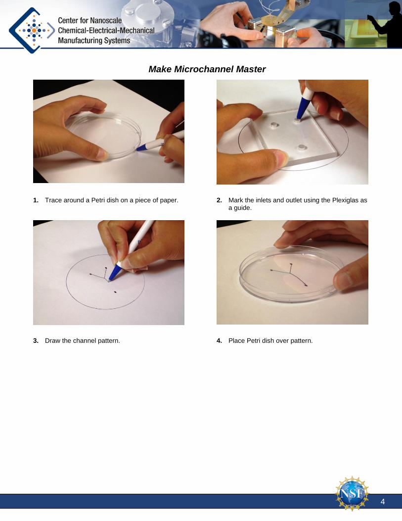
Make Microchannel Master
1. Trace around a Petri dish on a piece of paper.
2. Mark the inlets and outlet using the Plexiglas as a guide.
3. Draw the channel pattern. 4. Place Petri dish over pattern.

5
Univ
5. Trace pattern with Puffy Paint. 6. Allow to dry overnight.
Make Microchannels
7. Add 15 – 25 grams of PDMS elastomer base to a drinking cup (for 1 Petri dish).
8. Add 1/10 mass (1.5 – 2.5grams) of curing agent
crosslinker to the cup.
6
Univ
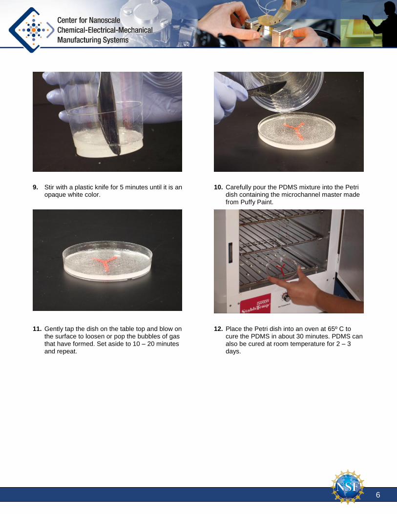
9. Stir with a plastic knife for 5 minutes until it is an opaque white color.
10. Carefully pour the PDMS mixture into the Petri
dish containing the microchannel master made from Puffy Paint.
11. Gently tap the dish on the table top and blow on the surface to loosen or pop the bubbles of gas that have formed. Set aside to 10 – 20 minutes and repeat.
12. Place the Petri dish into an oven at 65º C to
cure the PDMS in about 30 minutes. PDMS can also be cured at room temperature for 2 – 3 days.

7
Univ
Assemble Microchannel Device
13. When PDMS has cured (firm to the touch), carefully remove it from the dish with a spatula or another thin blunt object.
14. With channel side up, place a backing plate of
Plexiglas on the bottom of the microchannel device.
15. Add an inlet plate of Plexiglas to the top (channel side) of the microchannel device.
16. Add binder clips to hold the Plexiglas plates in
place.
17. Place in pan to collect fluid.

8
Univ
Determine Device Flow Results
18. Fill pipettes with colored fluid (food coloring in rubbing alcohol or water).
19. Position pipettes over inlet holes.
20. Carefully add liquids to microfluidic device, being careful to add liquid to both channels at about the same rate.
21. Observe results.

9
Univ
Presentation Details: Slide 1 (Microfluidics): We will be learning about a new technology, microfluidics. Microfluidics will
transform the way we do chemistry and biology, and lead to incredible advances in medicine.
Slide 2 (Objectives): We will discover what microfluidics is and why it is potentially so important. We
will make a simple microfluidic device and observe how fluids behave differently at the small scale.
Photo of a device screen for protein crystallization, courtesy of Dr. Paul Kenis’ lab group.
Slide 3 (What is it?): Microfluidics is a technology where very small amounts of fluids are manipulated
and analyzed.
Slide 4 (What is it?): The small volumes of liquid are routed along through tiny channels where they can
be reacted, analyzed, and manipulated in a device often called a “lab-on-a-chip.” These devices are called
that because of their similarity to computer chips.
Photo of a device to route inks to various locations for deposition, courtesy of Dr. Paul Kenis’ lab group.
Slide 5 (What is it?): Microfluidics is an alternative to traditional chemistry. But why would we need an
alternative? What limitations does traditional chemistry have?
Slide 6 (Traditional chemistry): Something most people don’t realize is just how many molecules are in
even a very small volume. Just one small drop of water contains ten sextillion molecules. That is a one
with 22 zeros after it! This is a very large number of molecules to collect. If these molecules need to be
synthesized, that is a lot of molecules that need to be made. That can make even one test very expensive.
With microfluidics, much smaller volumes are used. This means many fewer molecules need to be
isolated or created.
Slide 7 (Traditional chemistry): Although there are beakers and flasks to hold chemicals, the molecules
can easily spill to escape. If the molecules are hazardous, it is very easy to contaminate the area because it
can be very hard to contain them all.
With a microfluidic chip, the chemicals are confined inside the chip.
Slide 8 (Traditional chemistry): Traditional chemistry often requires expensive and specialized
equipment to run analysis with. These machines often require a clean space to be located, and some can
be very hard to move once they are in place. Often the chemicals need to be brought to the machines.
With a microfluidic chip, the circuits and sensors are all built right into the chip. These chips are small
and portable, basically allowing you to take the laboratory along with you.
Slide 9 (Traditional chemistry): Because a large number of molecules need to be created or isolated,
and because equipment isn’t always immediately available, there can be much time that passes before you
get your results. Sometimes results are needed quickly and that time isn’t available.
Microfluidic chips work with much fewer molecules and contain all the “equipment” on the chip, so the
time to get the results is significantly reduced.

10
Univ
Slide 10 (Benefits of Microfluidics): Here is a quick summary of some of the significant limitations of
traditional chemistry and how that compares to microfluidic devices. Notice that microfluidic devices are
cheap, quick and self contained. This makes them much easier to use and allows more people to be able to
do the important analysis that these chips can do.
Slide 11 (Why do it?): To fully understand the importance of this new technology, lets look at an
example; medicine in the developing world.
Slide 12 (Medicine in the third world): Many people in the developing world live in small villages or
on farms. Medical facilities are often a day’s travel away. If someone has to travel a long way for medical
care, many tend to not seek out that care for routine concerns. This delay in seeking care can result in a
much more severe prognosis.
Slide 13 (Medicine in the third world): When they do get to the facilities, there is often only a few,
overworked healthcare practitioners. This leads to long lines to wait for the care. Here is a typical line
outside one of these facilities.
Slide 14 (Medicine in the third world): The facilities are often ill-equipped. They tend to be small,
without much room for important supplies or machinery.
Slide 15 (Medicine in the third world): Because of the cost of equipment, there tends to not be much.
Often simple diagnostic tests can be hard or impossible to do in these facilities.
Slide 16 (Medicine in the third world): When it is available, electric power can often be limited and
inconsistent. Machines that require power may not have the power routinely available.
Slide 17 (Medicine in the third world): All of these issues often lead to a lower quality of care
compared to what we have come to expect here in the United States.
Slide 18 (Medicine in the third world): We can minimize or remove many of the barriers to quality
medical care in the developing world with microfluidics. These “lab-on-a-chip” devices give fast results,
eliminating the need for a patient to come in twice, once for diagnosis and a second time for treatment.
This is one of the major hurdles facing healthcare in the third world. Because of the travel involved, often
patients would not come in for a second visit, spreading disease and living with chronic conditions.
The cost is much less, making it possible to diagnose and treat many conditions that were just too
expensive to be effectively treated in these societies with limited resources.
It is possible to run these devices with little power, batteries and solar cells allow these devices to work in
any location, in comparison to traditional medicine needing a reliable source of high wattage electrical
power.
Because these devices are so small, healthcare workers can actually travel to the villages and farms of the
patients, bringing the “lab” with them. The health care workers can quickly and efficiently perform
complex diagnostic tests where the patient is.
Slide 19 (Applications): Microfluidic devices are not limited to “lab-on-a-chip” applications. There is
much research and development in using microfluidics to create sensors for a host of compounds.
Research at the University of Illinois is ongoing to design a sensor for bioterrorist compounds so that they

11
Univ
can be detected in such small amounts that the sensor would be able to detect these compounds as they
passed by the sensor, even if the compound was in a sealed container..
Another important application is in making inexpensive fuel cells. Using microfluidics, fuel cells can
produce more power and do it much cheaper then traditional designs.
As you can see, there are numerous applications of microfluidics, and these are just a small sampling.
Slide 20 (Applications): At Nano-CEMMS at the University of Illinois, they are using microfluidics to
create what can be thought of as basically an ink-jet printer. Except that instead of printing ink on paper,
this printer deposits chemicals on a variety of substrates. With this process, flexible displays could be
created or circuits could be embedded in fabrics so that clothing could monitor a persons health or
monitor their body temperature and adjust accordingly. With such a printer, a whole host of new products
and devices could be made. Things that now seem like only science fiction.
Slide 21 (Center research): In this animation, we see the printer depositing various compounds on a thin
glass substrate. Notice how the substrate moves, rather then the print heads. There are two print heads, but
each print head actually contains hundreds of individual nozzles. The size of these nozzles are very small.
You can see the aray of nozzels and as we zoom in, we see that the nozzle in only 50 nanometers across.
50 nanometers is a thousand times smaller then the width of human hair. Another way to think about this,
50 nanometers is only about 200 atoms thick. This is very small.
Slide 22 (Center research): In this sequence, we look inside of the printhead.
Various chemicals are fed into the system through traditional means. They enter the microfluidic network
where they are mixed, reacted, and routed to the proper print nozzle.
When the chemicals are ready for deposition onto the substrate, they can not simply be “squeezed” out.
With such small amounts of liquid, pressure will not drive the liquids reiably out. Instead a different
method needs to be used. Electrostatic forces are employed to drive the small drop out of the nozzle and
onto the substrate.
Slide 23 (Master): To make a microfluidic device, we start with a master which contains the pattern of
the channels. To make the pattern, raised sections will form the channels.
Slide 24 (PDMS mold poured): PDMS is poured over the master. The PDMS will become the
microfluidic device. The channels are made where the raised sections were in the master. Actually these
will form only three sides of the channel. The fourth side of the channels will be formed later.
Slide 25 (PDMS mold removed): The PDMS solidifies and is separated from the master.
Slide 26 (Top plate placed): The fourth wall of the channel is formed by a piece of Plexiglas or glass.
This is placed over the channels. To access the channels, holes are drilled through the Plexiglas. These
holes should line up with the ends of the channels.
Slide 27: Here we see the same procedure. PDMS is poured over the master. The PDMS solidifies and is
pulled off the master.

12
Univ
Slide 28: Here you can see how the master forms the channels. The Plexiglas forms the final wall of the
channel. The holes in the Plexiglas forms the inlets to the channels. The holes need to line up with the
ends of the channel.
Slide 29: After assembling the device, use pipettes to feed in the liquid. In our device, gravity will cause
the liquid to flow through the channels, but in most microfluidic devices, pumps are used to control the
flow rate of the liquids.
Slide 30 (Flow regimes): If red and blue water flow next to each other in a single channel, what will
immerge at to bottom?
Although it may seem obvious that the two will mix and produce purple water, that only happens if the
fluid flows turbulently. There is another type of flow regime. Fluids, under certain conditions, will instead
show laminar flow. The two colors of water will remain separated and immerge side-by-side, unmixed.
Slide 31 (Flow regimes): Fluids can flow one of two ways, either laminarly or turbulently. Laminar flow
is where the fluid streams flow side by side. They do not mix, although they will slowly diffuse together.
Turbulent flow is where the fluid streams mix and churn together. The streams rapidly combine and
become indistinguishable as separate streams.
Which manner the fluids will flow depends on a few characteristics. If the channels are small, the fluids
will tend to demonstrate laminar flow. If however, the channels are large, then fluids tend to demonstrate
turbulent flow.
When fluids flow fast, there tends to be more turbulence. When the flow is slow, the turbulence that
produces mixing is diminished and laminar flow is possible.
Viscosity is how thick a fluid is. Honey and molasses are viscous liquids, while water is not very viscous.
Viscous fluids tend to have laminar flow, while low viscosity fluids tend to be more turbulent.
Slide 32 (Which flow regime): So, assemble your microfluidic device and see which flow regime this
device will produce.

13
Univ
Notes:
For more information, contact: Center for Nanoscale Chemical-Electrical-Mechanical Manufacturing Systems; University of Illinois
at Urbana-Champaign, 4400 Mechanical Engineering Laboratory, 105 South Mathews Avenue, MC-244, Urbana, IL 61801
Phone: 217.265.0093 Email: [email protected] Website: http://www.nano-cemms.illinois.edu
Established in 2003, the Center for Nanoscale Chemical-Electrical-Mechanical Manufacturing Systems (Nano-
CEMMS) is funded by the National Science Foundation. Partnering Institutions include the University of Illinois,
North Carolina Agriculture and Technical State University, Stanford University, University of Notre Dame,
University of California – Irvine, and Northwestern University. Researchers are developing a nanomanufacturing
system that will build ultrahigh-density, complex nanostructures. The Center’s research will ultimately result in a
new way of working and has the potential to create millions of jobs for American workers. Our nation’s school
children must be prepared to assume the new roles that will be the inevitable outcome of these emerging
technologies.
This learning module is one of a series that is designed to interest middle and high school students in pursuing
this new field. The Center also offers ongoing professional development for teachers through a continuous series
of workshops and institutes. To sign up for a workshop or to order more learning modules, visit our website at
http://www.nano-cemms.illinois.edu.