Embed Size (px)
Citation preview

Computational Aesthetics in Graphics, Visualization, and Imaging (2010)O. Deussen and P. Jepp (Editors)
Learning about Shadows from Artists
Elodie Fourquet
AbstractRenaissance artists discovered methods for imaging realistic depth on a two dimensional surface by re-inventinglinear perspective. In solving the problem of depth depiction, they observed how shadows project and volumes flat-ten in nature. They investigated how controlled illumination projects volumes onto walls, exploring the phenomenalong before physical optics, such as the camera, existed. This paper specifically examines artists’ constructionsfor depicting shadows, a 3D double projection problem that artists solved completely within two dimensions. Thelarger goal is to develop new computational methods for creating 3D perceptions without having to leave the 2Dcanvas. Those methods have potential application in constructing user interfaces, in 2D image compositing andin simultaneous 2D/3D composition.This paper develops geometric constructions for casting shadows onto planar surfaces, adapted from artists’methods. Their algebraization for integration into imaging software is demonstrated, and their optically accuracyis shown. Finally, resulting images are included, along with a discussion of limitations.
Categories and Subject Descriptors (according to ACM CCS): I.3.3 [Computer Graphics]: Picture/ImageGeneration—Display algorithms; I.3.7 [Computer Graphics]: Three-Dimensional Graphics and Realism—Color,shading, shadowing, and texture; J.4 [Social and Behavioural Sciences]: Psychology;—J.5 [Arts and Humanities]:Fine arts—
1. Introduction
Renaissance painters opened up pictorial space into depthby re-inventing linear perspective. They gave objects 3D re-lationships in depth while controlling picture plane com-position. Achieving this double challenge, they created alarge collection of geometric constructions realisable witha straight-edge, in effect developing projective geometry.
Essential for easy depth perception and construction is astrong ground plane, often a tiled floor, which roots objectsin depth. An earlier paper [Fou08] showed how the groundplane can be combined with a compositional grid to inte-grate 2D and 3D composition. This paper examines shadowplacement, another technique painters used to strengthen theperception of depth. Research in picture perception showsthat shadows enhance understanding of the relative positionof objects [CL89, LGTT09]. Furthermore, they are seldomthe focus of vision and admit some freedom in depiction,which permits to simulate them convincingly with solely 2Dcomputations.
The constructions painters use to create correct shadowplacement perform perspective calculations geometrically.To replicate painters’ constructions within computer graph-
ics tools two important specifications are needed: the attach-ment point of an object, and the light vanishing point. Thesetwo points on the picture plane provide enough depth in-formation for solving the 3D double perspective projection,which determines shadow location and shape. Thus, the pa-per demonstrates that it is unnecessary to work in 3D in orderto create accurate shadows. Indeed, the paper introduces 2Dmatrix transformations that algebraically replicate the geo-metric constructions of artists.
This research is important because artists creating 2D im-ages prefer to manage composition within 2D environments,such as Photoshop or Illustrator, where for realism they useconstruction lines to get correct depth, sometimes at greatcost [Hus10]. Thus, since compositing and editing imagesin 2D is ubiquitous throughout the graphic arts, the resultspresented in this paper provide interesting opportunities forbetter supporting depth in 2D tools.
The paper begins by describing typical artists’ construc-tions for placing shadows, which are more in the natureof rules of thumb than algorithms. Therefore, those de-scriptions are complemented with the special considerationsneeded to encode artists’ tacit knowledge and practice withinthe computer. It then shows how to algebraize the most ba-
c© The Eurographics Association 2010.

Elodie Fourquet / Learning about Shadows from Artists
sic construction. A full implementation is used to create avariety of images with shadows, illustrating the range of themethods and how they anchor objects in space. The maincontribution of this paper is formalizing and implement-ing artists’ geometrical rules for calculating shadows, anddemonstrating that the formalization is optically accurate.
2. Previous Work
Despite many well-featured commercial 2D image creationenvironments, many of which, such as Photoshop or Java2D,support a variety of affine transformations, there is little re-search on manipulating 3D perspective in 2D. The expla-nation, most likely, is the development of computer graphicsprimarily by scientists and engineers. The earliest formaliza-tions of geometry in computer graphics were 3D, modellingusing affine transformations with a single perspective trans-formation for projecting to the 2D image. Image creationapplications based on 3D geometry have been technicallysuccessful, but, based on poor uptake by visual artists, theyseem to offer inadequate support for the creation of artisti-cally interesting images.
More specifically, there is negligible support for realisticshadows in 2D graphics. The single exception is 2 1
2 D userinterfaces, which use drop shadows extensively for separat-ing interface components in depth [Wil91]. The techniquesfor making them are, however, ad hoc, and unconnected withexplicit depth or illumination.
There exist several studies of the effectiveness of ma-nipulating shadows as a method for controlling illumina-tion: for example, users dragging shadow volumes [PF92]or shadows [PTG02] in the image. Direct manipulation oflights in the image seems most effective. Other research addsshadows to existing images, allowing users to add shadowsfrom non-existent sources of illumination [Bar97] or to addshadows cast by non-existent objects [PFWF00, KP09]. No-table among this research are algorithms that stylize shadowmattes calculated from 3D illumination models [DCFR07].This research follows the practice of artists, who eliminateinessential details of shadows, keeping only details that helpthe user to perceive the object.
There is a large body of recent research that uses scenesderived from 2D material as the source of new scenes or asadditions to other scenes, which is too extensive for review.Occasionally – Shesh et al. [SCRS09] is one such example– shadows are added. However, the methods are explicitly3D, and operate on partial 3D information reconstructed byestimating the homography that created the scene, using acomputer vision technique [HZ04]. The research describedhere uses homographies, but for a quite different purpose,for image creation rather than scene reconstruction, usingimage plane illumination key points. These transformationsgo under a wide variety of names, such as projective trans-formations, projections [Sti05] or projectivities [Cox74]. Wecall them collineations, the term that seems in widest use.
3. Artists’ Constructions
Figure 1: Three illustrations from chapter XV, Perspectiveof Shadows, of Cole’s manual.
Artists draw shadows by placing light sources in the im-age, then drawing construction lines from them. This sectiondescribes constructions that draw optically accurate shadowsusing only a straight-edge. The constructions are geometri-cal solutions of double projection equations.
Published early in the twentieth century, Rex Vicat Cole’smanual [Col21] collects many illustrations of artists’ con-structions, including ones for calculating shadow geome-try. Figure 1 shows three illustrations of shadow construc-tions. Notice the vanishing point of each light source, whichminimally encodes enough information to define projectionsfrom the lights. Cole’s descriptions are incomplete: he ex-pects the artist to complement them with tacit knowledge.Implementing the constructions the tacit must be made ex-plicit, one contribution of this paper.
3.1. Placing Lights in 2D
Ground plane geometry is defined by two points. The sceneprincipal vanishing point, at eye level in the direction of theviewer’s gaze, sets the height of the horizon. The scene dis-tance point, on the horizon often on the frame, defines theviewer’s distance from the scene [Fou08].
Lights, which are centres of projection for shad-ows [Bli88], also have light vanishing points, which areagain centres of projection, directly below the light on theground plane. Artists position a light in the image, then drawa vertical line terminating on the ground plane at the lightvanishing point, defining the light’s depth. In contrast withlights near the image plane, distant lights, like the sun, havevanishing points on the horizon.
In two cases lights cannot be located on the canvasstraightforwardly. In the first case the light is in front ofthe viewer beyond the frame, high overhead or far to theside. Such lights produce minimally foreshortened shadowsand parallel construction lines from the direction of the lightsource correctly describe the shadows. In the second casethe light is behind the viewer. In this configuration artistsuse a pseudo-light, positioned approximately where the lightprojects through the viewer’s eye onto the image plane. Withit they can construct shadows produced by illumination frombehind. Indeed, in practice, the artist does not project exactlythe light through the eye: the light vanishing point is posi-tioned on the ground plane with the pseudo-light below it,
c© The Eurographics Association 2010.
Elodie Fourquet / Learning about Shadows from Artists
and the two positions are moved until the shadows enhancethe overall composition.
Figure 2: Illumination shading a point on the ground floor.Both the illumination vanishing point and the point attach-ment point must be known for the construction.
3.2. Shadows on the Ground Plane
Objects in the image need attachment points, which do forthem what light vanishing points do for lights. They arepositioned on the ground plane directly below each object,defining its depth. Lines drawn from a light vanishing pointthrough an object’s attachment point show the direction inwhich the shadow is cast.
The basic shadow construction is illustrated for a pointin Figure 2. A ground ray is drawn from the light vanish-ing point through the attachment point. Then, a light ray,is drawn from the light source through the shadow-castingpoint. The point’s shadow falls on the ground plane at theirintersection. Of course, if the point happens to be on theground plane, it coincides with both its attachment point andits shadow.
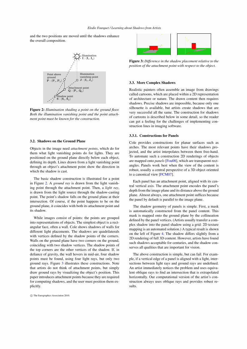
While images consist of points: the points are groupedinto representations of objects. The simplest object is a rect-angular face, often a wall. Cole shows shadows of walls fordifferent light placements. The shadows are quadrilateralswith vertices defined by the shadow points of the corners.Walls on the ground plane have two corners on the ground,coinciding with two shadow vertices. The shadow points ofthe top corners are the other vertices of the shadow. If, indefiance of gravity, the wall hovers in mid-air, four shadowpoints must be found, using four light rays, but only twoground rays. Figure 3 illustrates these constructions. Notethat artists do not think of attachment points, but simplydraw ground rays by visualizing the object’s position. Thispaper introduces attachment points because they are requiredfor computing shadows, and the user must position them ex-plicitly.
Figure 3: Difference in the shadow placement relative to theposition of the attachment point with respect to the object.
3.3. More Complex Shadows
Realistic painters often assemble an image from drawingscalled cartoons, which are placed within a 2D representationof architecture or nature. The drawn content then requiresshadows. Precise shadows are impossible, because only onesilhouette is available, but artists create shadows that arevery successful all the same. The construction for shadowsof cartoons is described below in some detail, so the readercan get a feeling for the challenges of implementing con-struction lines in imaging software.
3.3.1. Constructions for Panels
Cole provides constructions for planar surfaces such asarches. The most relevant points have their shadows pro-jected, and the artist interpolates between them free-hand.To automate such a construction 2D renderings of objectsare mapped onto panels [Fou08], which are transparent rect-angles. Panels work best when the view of the content isrobust, usually a central perspective of a 3D object orientedto a canonical view [FCM07].
Each panel has an attachment point, aligned with its cen-tral vertical axis. The attachment point encodes the panel’sdepth from the image plane and its distance above the groundplane. Almost always, one attachment point suffices becausethe panel by default is parallel to the image plane.
The shadow geometry of panels is simple. First, a maskis automatically constructed from the panel content. Thismask is mapped onto the ground plane by the collineationdefined by the panel vertices. (Artists usually transfer a com-plex shadow into the panel shadow using a grid: 2D texturemapping is an automated solution.) A typical result is shownon the left of Figure 4. The shadow differs slightly from a2D rendering of full 3D content. However, artists have foundsuch shadows acceptable for centuries, and the shadow con-serves all qualities that are important for vision.
The above construction is simple, but can fail. For exam-ple, if a vertical edge of a panel is aligned with a light, inter-sections between light rays and ground rays are undefined.An artist immediately notices the problem and uses equiva-lent oblique rays to find an intersection that is extrapolatedhorizontally. Our computational version of the artist’s con-struction always uses oblique rays and provides robust re-sults.
c© The Eurographics Association 2010.

Elodie Fourquet / Learning about Shadows from Artists
Figure 4: Constructions for ground shadows. On the left, theillumination is a sun (horizon vanishing point). On the right,baseline intersection points from the ground rays are used toonly consider the region that shades behind the image plane.
Another case needing a more robust construction occurswhen the shadow of a panel extends beyond the pictureframe. The simple algorithm – draw the entire shadow andclip to the frame – is impossible in general because shadowsbecome infinitely long as the distance of the light from theground plane approaches the height of the panel. Thus, theshadow must be cut off at the frame initially. The intersec-tions of ground rays with the frame mark the extend of thevisible shadow. Projected back to the panel they are the ver-tices of the polygon containing the content to be projected.
A more extreme case occurs when the distance of the lightabove the ground plane is less than the height of the panel.Then, the ground ray/light ray intersections are between thelight’s vanishing point and the horizon. The shadow then in-correctly lies on the lighted side of the panel and its edgesintersect one another. This case is easy to identify becausethe light vanishing point lies inside the shadow. When thiscondition is detected the construction described in the previ-ous paragraph gets the shadow correct.
3.3.2. Other Shadows
In addition to completing Cole’s constructions it was nec-essary to create many new constructions for more complexshadow geometries. These include shadows cast on planesparallel to the ground plane, which requires the attachmentpoints and the light vanishing point to be defined on theshadow plane (Figures 5 and 6), shadows cast on vertical sur-faces parallel to the image plane, shadows split between twosurfaces (Figures 7 and 8), shadows on planes perpendicularto the floor and the image plane (Figure 8), and shadows ofrotated panels (Figure 8).
3.4. Summary
This section describes by example a formalization of artists’constructions for shadows as algorithms, which successfullycomplete them in accord with artists’ intuitions, and pro-vides methods for creating many new constructions. Every-thing described was implemented using only line intersec-
Figure 5: Panel projection on an elevated ground. Only thepanel part above the height defined by the volume is consid-ered. Ground rays and light vanishing point on the elevatedsurface need to be used.
Figure 6: Constructions for shadows on an elevated ground.The left image shows how the projected shadow quad is eval-uated. The right image shows how the elevated light vanish-ing point is evaluated from the volume perspective.
tion calculations, to prove that all these algorithms are imple-mentable by artists working on the image plane, and withoutmeasurement. It shows that artists can work exclusively in2D while creating the projection of an optically correct 3Dvolume.
The implementation is important as ground truth against
Figure 7: Pseudo-illumination creating a ground shadowthat continues onto a face that is parallel to the image plane,and is visible to the viewer. Light rays are used to map therelevant regions.
c© The Eurographics Association 2010.

Elodie Fourquet / Learning about Shadows from Artists
Figure 8: Rotated panels creating shadows on the groundplane and on a lateral face of a volume. Parallel lines on therotated panel converge on the horizon.
which the algebraic 2D formalism introduced in the next sec-tion can be tested. It reformulates the basic construction interms of 2D projective geometry, which is easier to imple-ment, and which is well-adapted to current graphics hard-ware.
4. Mathematical Theory
2D collineations, represented as homogeneous matrices, per-form the geometric computations described in the previ-ous section more flexibly and efficiently than simulated Eu-clidean geometry. The collineations demonstrate the gener-ality of artists’ constructions, ease the implementation, andintegrate artists’ constructions with existing 2D graphicssoftware. This section presents the 2D matrix correspond-ing to the geometric construction of shadows on the ground.Then, it is shown that the 2D construction is optically cor-rect by solving the equivalent 3D problem. To show the tech-nique the mapping from a panel to its shadow on the groundplane is derived in detail, but collineations that perform othershadow projections are omitted owing to restricted space.
4.1. Collineations for Ground Shadows
This section calculates homogeneous matrix representationsof collineations for the geometric shadows of Section 3 in theartists’ coordinate system: origin at the centre of the base-line, x increasing to the right, y upward. The scene vanishingpoint is centered on the horizon, at (0,Eh). The scene dis-tance point is at (±Ed ,Eh). The light source is labeled I, itsvanishing point J, shadow casting points P, and their attach-ment points Q. The notation is illustrated in Figure 2.
The 2D formalism is based on a transformation that mapsa point P on a panel with attachment point Q, to S, its shadowon the ground plane. The shadow lies at the intersection oftwo lines: Ł1(t) = P + t(I−P) and Ł2(s) = Q + s(J−Q).By definition, Qx = Px and Jx = Ix. Thus, s = t, and
t = (Qy−Py)/(−Py + Iy−Jy−Qy), resulting in
Sx =PxIy−PxJy−PyIx + IxQy
−Py + Iy−Jy +Qyand
Sy =−PyJy + IyQy
−Py + Iy−Jy +Qy,
a Möbius transformation with real coordinates. Thus, the fol-lowing matrix represents the transformation that maps thecoordinates of P to the coordinates of its shadow S.
SxSy1
∼
Iy−Jy −Ix IxQy0 −Jy IyQy0 −1 Iy−Jy +Qy
PxPy1
,
where ∼ means ‘is the same point as’. The light position (Iand J) are parameters of the transformation, as is the panelattachment point (Q). Therefore, the matrix does not varyfrom point to point, only from panel to panel. The mappingdepends only on points in the image plane: no 3D calcula-tions are performed.
Collineations implementing the other shadow construc-tions mentioned in Section 3, are derived using similar tech-niques, together with the collineation defining the scene per-spective, as encoded by the tiled floor construction. Calcu-lating 3D properties using only 2D collineations is possiblebecause the attachment points and light vanishing points en-code just enough 3D information, and encode it so it is ac-cessible in 2D. This important observation is a contributionof the paper.
4.2. 3D Equivalence
The previous subsection derived a homogeneous matrix rep-resenting the collineation for geometric constructions ofground shadows. This one proves that the constructions areoptically accurate.
There is a direct simple proof. Examining Figure 9, wevisualize in 3D the scene it portrays. A line, from the lightsource through a shadow-casting point, intersects the groundplane at the shadow. A second line, from the light vanish-ing point through the attachment point, lies on the groundplane and meets the first line where it intersects the groundplane. An intersection is guaranteed because the two linesare coplanar. Projection to the image plane maps preservesintersections, so that the shadow on the image plane lies atthe intersection of the projected eye and ground rays.
Such reasoning, plus the image before their eyes, con-vinces artists that the construction is correct. However, al-gebraic calculation is the medium of computer graphics, andleads more directly to algorithmic expression. Therefore, asecond proof calculates the projection geometry in 3D andderives the corresponding 2D collineation. The presentationis in the style of Blinn [Bli88].
c© The Eurographics Association 2010.

Elodie Fourquet / Learning about Shadows from Artists
Figure 9: The shadow casting geometry is shown in anorthogonally-projected side view. i is the light source; j itsvanishing point. p is the shadow-casting point; q its attach-ment point. The shadow falls on the ground at s. These pointsare projected to the image plane through the viewer’s eye E.Their images have the same label, but uppercase.
The 3D geometry is shown in Figure 9. We show that theprojected shadow point, S, can be calculated using only theprojected points, I, J, P and Q. To do so we calculate the 3Dpoints from projected points, and substitute them into theprojected location of the shadow. In 3D the shadow falls ats∼ Σp, where
Σ =
−iy ix 0 00 0 0 00 iz −iy 00 1 0 −iy
.
In Σ the row of zeros occurs because the shadow is cast onthe floor, y = 0. The shadow is projected to the image plane,using the projection centre E = (Ex,Eh,Ed), with the matrix
Π =
−Ed 0 Ex 0
0 −Ed Eh 00 0 0 00 0 1 −Ed
so that S ∼ ΠΣp. We now calculate p and i. Indeed, p isderived from the following matrix Γ,
p∼ Γ
PxPyQy1
=
−Eh 0 Ex 0
0 −Eh Eh 00 0 Ed 00 0 1 −Eh
PxPyQy1
.
In the product ΠΣΓ we substitute i = Γ(Ix, Iy, Jy, 1)T andplace the eye E in the world frame at Ex = 0. (With this pro-jection a pseudo-light appears on the image plane by project-ing it through the eye of the viewer.) Thus, we obtain
S∼
Iy−Jy −Ix Ix 0
0 −Jy Iy 00 0 0 00 −1 1 Iy−Jy
PxPyQy1
,
which can be simplified to the transformation obtained inSection 4.1, proving that the artists’ construction is opticallycorrect.
5. Implementation and Results
The techniques of this paper have been implemented as aprototype application, with an interaction model that wouldbe useful for artists roughing out volumes in a 2D realisticimage, or for stage designers planning the use of space ona stage as seen by the audience. The goal of the prototype,however, is not to provide a practical tool, but to provide atest-bed for the formalism.
5.1. Implementation
The prototype is implemented in Java, using the Java2D API.Both geometric construction methods and 2D collineationsare represented as 2D homogeneous matrices. This sectionhighlights non-standard aspects of the implementation.
5.1.1. Panels and Shadows
Drawn on each panel is a 2D image, its content, which iscreated off-line. The image is often the central axis projec-tion of a 3D object, but may be any 2D content. The contentis opaque, the rest of the panel transparent. Shadows use thecontent as a mask. Classes implementing non-affine matricesand filters map the shadow colour through the mask onto theshadow plane. Shadows that coincide are combined using il-lumination attributes. The combined shadow can be given asmoke-like outline or made semi-transparent.
The prototype also includes rectangular blocks, whichare commonly used to rough out volumes. Blocks are tile-aligned and can be stacked. Panels placed on block faces arescaled so that panel corners coincide with face corners.
5.1.2. Occlusion by Clipping
A painter’s algorithm combined with 2D clipping andcompositing provides correct occlusion. It uses geometry-guaranteed patterns in block/block and block/panel occlu-sion among unit blocks. Scene elements are drawn row byrow, from the horizon to the baseline. Within a row theyare drawn from the frame toward the mid-line of the image.Within a tile, blocks, which may be stacked, are drawn frombase to horizon, with any part of the block above the horizondrawn from its top down to the horizon. Except for infre-quent floating point round-off artifacts, visible in Figure 8,rendering is flawless, including shadows and panels on blockfaces.
5.1.3. The Interface
The composition interface is drag-and-drop for panels andfor points that define the geometry, like vanishing points, at-tachment points, and light sources. Each panel can be scaledor translated by dragging. Note that only the y-coordinate ofpanel attachment points is editable, the x-coordinate beingdetermined by panel location. From a selected set of tiles,blocks are extruded upward using the scroll wheel. The pro-totype runs at interactive frame rates on a mediocre Linuxbox, 3 GHz Pentium 4 with 1 Gbyte of memory.
c© The Eurographics Association 2010.

Elodie Fourquet / Learning about Shadows from Artists
Figure 10: Shadow effect from a rotating panel. Birdshadow with fuzzy edges.
Figure 11: Shadows of volumes and of a vase.
5.2. Results
All colour figures in the paper were created using the pro-totype. They illustrate important aspects of the shadow al-gorithms. In some cases construction lines, dashed and incolour, were manually added to guide the eye.
The left pair of images in Figure 10 compare shadows caston the ground by a panel parallel to the image plane and bythe same panel slightly rotated. Owing to the shadow, thewoman is perceived as rooted firmly on the ground, eventhough her feet are awkwardly drawn. The gap between el-bow and body is more visible in the shadow than on thepanel. The rotated panel/woman produces an equally satis-factory shadow. Shadows can be surprising. The right imageshows the shadow of a dove that is more birdlike than thebird itself.
Figure 11 shows shadows of volume faces. The upper im-age shows the shadow from an off-canvas directional light,its direction determined by the oblique line. The lower leftimage is the same scene lit with a back light on the left. Inthose images the shadows are semi-transparent: idempotentcombination ensures that opacity does not add. The lowerright image is a vase and its shadow, the vase derived froma painting by Vanderlyn. DeCoro et al. used it to illustrate amethod for artistic simplification of 3D shadows [DCFR07].Projecting from a panel, as artists generally do, gives a sim-ilar simplified result, but as the default case.
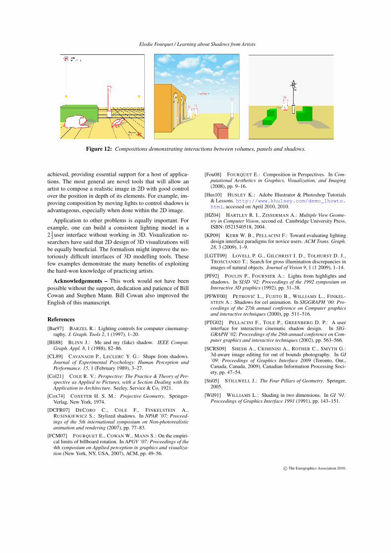
Figure 12 shows more complex images created using theprototype. The leftmost image shows shadows cast by apseudo-light, pointing toward the light vanishing point. Thecentre image has eight panels and two volumes, with shad-ows that create strong visual relationships between panelsand volumes. Finally, the rightmost image is lit from the cen-tre of the picture, with shadows that diverge in all directions.
6. Discussion
For centuries artists and designers have manipulated shad-ows in 2D using rules of thumb acquired by experience.These rules can be completed and formalized. Essential forformalization are attachment points of objects and vanish-ing points of lights, which encode in the image just enoughdepth information to determine shadow geometry.
Lights can be manipulated in 2D by dragging them ortheir vanishing points. Recently, Kerr and Pellacini [KP09]showed that novice users best manipulate lighting directly,by moving light sources in 3D, or indirectly, by draggingshadows and highlights in 2D, with the latter preferred. Mostlikely this result shows that the familiarity of 2D overcomesthe disadvantage of indirection. If this interpretation is cor-rect interacting directly with lights in 2D is even better, avindication of learning from artists.
Also worth considering is shadow perception. Workingdirectly in 2D limits the quality of shadows: is the artists’practice an unavoidable comprise of image quality? Or arefull 3D shadows overkill, computing perceptually unimpor-tant details? Vision scientists [CL89] suggest that only afew aspects of shadows are important for vision. For ex-ample, shadows attached to an object root it on the groundplane, while detached ones place it in the air. Figure 10shows the difference. Consistent shadow orientations are im-portant [LGTT09]. Average orientation indicates the direc-tion of the light; variation of orientations the distance tothe light. Both are preserved by 2D shadows. Other impor-tant features, shadow edges, the relative lightness of shad-owed and non-shadowed regions [CL89], are also correct.Finally, shadows give information about the geometry of thesurface on which they are cast. When 2D shadows extendover several surfaces, as illustrated in Figure 12, they clearlystrengthen perception of surfaces.
In summary, while the shadows presented in this paperhave limitations, they capture the visually salient aspects ofshadows. Presumably, other aspects are less important be-cause shadows are rarely the focus of attention.
7. Conclusion
The goals of this research were three: to capture in algo-rithms the tacit knowledge with which artists complete their2D constructions of shadows; to show the algorithms to beequivalent to 2D collineations: and to demonstrate the con-structions to be optically correct. These objectives have been
c© The Eurographics Association 2010.
Elodie Fourquet / Learning about Shadows from Artists
Figure 12: Compositions demonstrating interactions between volumes, panels and shadows.
achieved, providing essential support for a host of applica-tions. The most general are novel tools that will allow anartist to compose a realistic image in 2D with good controlover the position in depth of its elements. For example, im-proving composition by moving lights to control shadows isadvantageous, especially when done within the 2D image.
Application to other problems is equally important. Forexample, one can build a consistent lighting model in a2 1
2 user interface without working in 3D. Visualization re-searchers have said that 2D design of 3D visualizations willbe equally beneficial. The formalism might improve the no-toriously difficult interfaces of 3D modelling tools. Thesefew examples demonstrate the many benefits of exploitingthe hard-won knowledge of practicing artists.
Acknowledgements – This work would not have beenpossible without the support, dedication and patience of BillCowan and Stephen Mann. Bill Cowan also improved theEnglish of this manuscript.
References[Bar97] BARZEL R.: Lighting controls for computer cinematog-
raphy. J. Graph. Tools 2, 1 (1997), 1–20.
[Bli88] BLINN J.: Me and my (fake) shadow. IEEE Comput.Graph. Appl. 8, 1 (1988), 82–86.
[CL89] CAVANAGH P., LECLERC Y. G.: Shape from shadows.Journal of Experimental Psychology: Human Perception andPerformance. 15, 1 (February 1989), 3–27.
[Col21] COLE R. V.: Perspective: The Practice & Theory of Per-spective as Applied to Pictures, with a Section Dealing with ItsApplication to Architecture. Seeley, Service & Co, 1921.
[Cox74] COXETER H. S. M.: Projective Geometry. Springer-Verlag, New York, 1974.
[DCFR07] DECORO C., COLE F., FINKELSTEIN A.,RUSINKIEWICZ S.: Stylized shadows. In NPAR ’07: Proceed-ings of the 5th international symposium on Non-photorealisticanimation and rendering (2007), pp. 77–83.
[FCM07] FOURQUET E., COWAN W., MANN S.: On the empiri-cal limits of billboard rotation. In APGV ’07: Proceedings of the4th symposium on Applied perception in graphics and visualiza-tion (New York, NY, USA, 2007), ACM, pp. 49–56.
[Fou08] FOURQUET E.: Composition in Perspectives. In Com-putational Aesthetics in Graphics, Visualization, and Imaging(2008), pp. 9–16.
[Hus10] HUSLEY K.: Adobe Illustrator & Photoshop Tutorials& Lessons. http://www.khulsey.com/demo_1howto.html, accessed on April 2010, 2010.
[HZ04] HARTLEY R. I., ZISSERMAN A.: Multiple View Geome-try in Computer Vision, second ed. Cambridge University Press,ISBN: 0521540518, 2004.
[KP09] KERR W. B., PELLACINI F.: Toward evaluating lightingdesign interface paradigms for novice users. ACM Trans. Graph.28, 3 (2009), 1–9.
[LGTT09] LOVELL P. G., GILCHRIST I. D., TOLHURST D. J.,TROSCIANKO T.: Search for gross illumination discrepancies inimages of natural objects. Journal of Vision 9, 1 (1 2009), 1–14.
[PF92] POULIN P., FOURNIER A.: Lights from highlights andshadows. In SI3D ’92: Proceedings of the 1992 symposium onInteractive 3D graphics (1992), pp. 31–38.
[PFWF00] PETROVIC L., FUJITO B., WILLIAMS L., FINKEL-STEIN A.: Shadows for cel animation. In SIGGRAPH ’00: Pro-ceedings of the 27th annual conference on Computer graphicsand interactive techniques (2000), pp. 511–516.
[PTG02] PELLACINI F., TOLE P., GREENBERG D. P.: A userinterface for interactive cinematic shadow design. In SIG-GRAPH ’02: Proceedings of the 29th annual conference on Com-puter graphics and interactive techniques (2002), pp. 563–566.
[SCRS09] SHESH A., CRIMINISI A., ROTHER C., SMYTH G.:3d-aware image editing for out of bounds photography. In GI’09: Proceedings of Graphics Interface 2009 (Toronto, Ont.,Canada, Canada, 2009), Canadian Information Processing Soci-ety, pp. 47–54.
[Sti05] STILLWELL J.: The Four Pillars of Geometry. Springer,2005.
[Wil91] WILLIAMS L.: Shading in two dimensions. In GI ’91:Proceedings of Graphics Interface 1991 (1991), pp. 143–151.
c© The Eurographics Association 2010.