Embed Size (px)
Citation preview

Leaky surface electromagnetic waves ona high-index dielectric gratingA. A. MARADUDIN,1 I. SIMONSEN,2,* AND W. ZIERAU3
1Department of Physics and Astronomy, University of California, Irvine, California 92697, USA2Department of Physics, NTNU Norwegian University of Science and Technology, NO-7941 Trondheim, Norway3Institute for Condensed Matter Theory, University of Muenster, D48149 Muenster, Germany*Corresponding author: [email protected]
Received 26 January 2016; revised 29 March 2016; accepted 7 April 2016; posted 7 April 2016 (Doc. ID 256636); published 6 May 2016
We show theoretically that the periodically corrugated sur-face of a high-index dielectric medium can support a leakysurface electromagnetic wave. This wave is bound to thesurface in the vacuum, but radiates into the dielectric.Despite this radiative damping, the surface wave can havea long lifetime. © 2016 Optical Society of America
OCIS codes: (050.0050) Diffraction and gratings; (240.0240) Optics
at surfaces; (240.6690) Surface waves.
http://dx.doi.org/10.1364/OL.41.002229
It is well known that a planar vacuum–dielectric interface doesnot support a surface electromagnetic wave of either p or spolarization when the dielectric constant of the dielectricmedium is real and positive. Such a surface also does not sup-port a leaky surface wave. In this Letter, we show that if thevacuum–dielectric interface is periodically corrugated insteadof planar and the dielectric constant of the dielectric mediumis real, positive, and large, it can support a leaky surface wave.This wave is bound to the surface in the vacuum region butradiates into the dielectric medium.
In order to avoid any misunderstanding, we note that if thedielectric medium has a complex dielectric constant whose realpart is positive and constant, and whose imaginary part is pos-itive, constant, and larger than the real part, its planar interfacesupports a generalized surface wave [1]. However, this wave isattenuated by the ohmic losses in the dielectric. For this reason,we do not consider lossy dielectric media in this Letter.
Our calculations are guided by the following considerations.A periodically corrugated, perfectly conducting surface in con-tact with vacuum supports a p-polarized surface electromag-netic wave that, in the simplest case, propagates normally tothe generators of the surface [2]. If the substrate supportingthis wave departs slightly from perfect conductivity, it is tempt-ing to assume that the surface wave is slightly perturbed, butstill exists. There are two ways to approach perfect conductivity.The most commonly considered one is to assume a metal atlower and lower frequencies at which the real part of its dielec-tric function is negative and approaches negative infinity. Thesecond approach is to assume a dielectric medium characterized
by a real, positive, frequency-independent dielectric constantthat is allowed to become larger and larger.
With the latter approach in mind, in this Letter, we studythe propagation of a p-polarized surface electromagnetic waveon a high-index dielectric grating and examine the conditionsfor its existence. In view of the current interest in alternativeplasmonic materials [3], the existence of such a wave on alossless medium should be of interest.
The physical system we study consists of a dielectricmedium whose dielectric constant is ε1 in the region x3 >ζ�x1� and a dielectric medium whose dielectric constant isε2 in the region x3 < ζ�x1�. We assume that both ε1 andε2 are real, positive, and frequency independent. The interfaceprofile function ζ�x1� is assumed to be single valued, differen-tiable, and a periodic function of x1 with period a,ζ�x1 � a� � ζ�x1�. We consider the case of a p-polarizedelectromagnetic field in this system, whose plane of incidenceis the x1x3 plane.
We begin by considering the diffraction in reflection andtransmission of a plane wave of frequency ω incident fromthe region x3 > ζ�x1� on the interface x3 � ζ�x1�. Thedispersion relation for the surface electromagnetic wave sup-ported by the interface can be extracted from the equationfor the diffraction amplitudes, while the degree to which thediffracted and refracted fields satisfy unitarity provides anindication of the accuracy of our numerical work.
The single nonzero component of the magnetic field in theregion x3 > ζ�x1� that satisfies the boundary conditions asx3 → ∞ of an incoming incident wave and outgoing diffractedbeams, and the Floquet–Bloch condition due to the periodicityof the interface, can be written as
H>2 �x1; x3jω� � exp�ikx1 − iα1�k;ω�x3�
�X∞n�−∞
An�k;ω� exp�iknx1 � iα1�kn;ω�x3�:
(1)
Here kn � k � 2πn∕a and αj�k;ω� � �εj�ω∕c�2 − k2�12. Thereduced Rayleigh equation for the diffraction amplitudesfAn�k;ω�g is [4]
Letter Vol. 41, No. 10 / May 15 2016 / Optics Letters 2229
0146-9592/16/102229-04 Journal © 2016 Optical Society of America

X∞n�−∞
Mmn�k;ω�An�k;ω� � −Nm�k;ω�; m ∈ N; (2)
where
Mmn�k;ω� �Im−n�α2�km;ω� − α1�kn;ω��
α2�km;ω� − α1�kn;ω�× �kmkn � α2�km;ω�α1�kn;ω��; (3a)
Nm�k;ω� �Im�α2�km;ω� � α1�k;ω��α2�km;ω� � α1�k;ω�
× �kmk − α2�km;ω�α1�k;ω��: (3b)
In Eq. (3), we have introduced the function
Im�γ� �1
a
Z a2
−a2
dx1 exp
�−i2πma
x1
�exp�−iγζ�x1��: (4)
The manner in which the branch cuts defining the square rootsin the definitions of α1�k;ω� and α2�k;ω� are chosen will bedescribed below.
The diffraction efficiency of the mth scattered beam isdefined as the fraction of the total time-averaged incident fluxthat is diffracted into this beam. It is given by
e�s�m � α1�km;ω�α1�k;ω�
jAm�k;ω�j2: (5)
The reflectivity is given by e�s�0 .The single nonzero component of the magnetic field in the
region x3 < ζ�x1� that satisfies the boundary condition ofoutgoing refracted beams as x3 → −∞ can be written as
H<2 �x1; x3jω� �
X∞n�−∞
Bn�k;ω� exp�iknx1 − iα2�kn;ω�x3�: (6)
The reduced Rayleigh equation for the refraction amplitudesfBn�k;ω�g is [4]
X∞n�−∞
Im−n�α2�kn;ω� − α1�km;ω��α2�kn;ω� − α1�km;ω�
× �kmkn � α1�km;ω�α2�kn;ω��Bn�k;ω�
� δm02ε2α1�k;ω�ε2 − ε1
; m ∈ N: (7)
The refraction efficiency of the mth transmitted beam is
e�t�m � ε1α2�km;ω�ε2α1�k;ω�
jBm�k;ω�j2: (8)
In this lossless structure, the conservation of energy indiffraction and refraction (unitarity) is expressed byX
m0 e�s�m �
Xm0 e�t�m � 1; (9)
where the primes on the sums mean that they are taken overonly the open channels, i.e., those for which α1�km;ω� andα2�km;ω� are real.
To obtain the dispersion relation for the surface electromag-netic waves by the periodically corrugated interface betweentwo dielectric media, we have only to remove the incident fieldfrom the right-hand side of Eq. (1). This is equivalent todeleting the inhomogeneous term from Eq. (2). In this way,we obtain the homogeneous system of equations for theamplitudes fAn�k;ω�g:
X∞n�−∞
Mmn�k;ω�An�k;ω� � 0; m ∈ N: (10)
The solvability condition for this system of equations,namely the vanishing of the determinant of the matrixM�k;ω�,
D�k;ω� � det�Mmn�k;ω�� � 0; (11)
is the dispersion relation we seek. The same dispersion relationis obtained from the homogeneous version of Eq. (7).
The magnetic field of the surface wave in medium 1 is thengiven by the second term on the right-hand side of Eq. (1):
H>2 �x1; x3jω� �
X∞n�−∞
An�k;ω� exp�iknx1 � iα1�kn;ω�x3�:
(12)
The magnetic field of the surface wave in medium 2 is stillgiven by Eq. (6).
In the determination of the dispersion curve of the surfaceelectromagnetic wave, for specificity, we will assume that theregion x3 > ζ�x1� is vacuum, while the region x3 < ζ�x1� isthe high-index dielectric medium. Thus we will assume thatε1 � 1, while ε2 � ε. The dispersion curve is insensitive tothe interchange ε1↔ε2.
There are two light lines in this problem. One is the vacuumlight line, ω � ck. The wavenumber k has to be larger thanω∕c in order that the electromagnetic fields in the vacuum re-gion be bound to the surface. The second light line is thedielectric light line ω � ck∕
ffiffiffiε
p. The wavenumber k must
be larger thanffiffiffiε
p �ω∕c� in order that the electromagnetic fieldin the dielectric be bound to the surface. In the region betweenthese two light lines, the surface wave is a leaky wave: it isbound to the surface in the vacuum and radiates into the di-electric. The frequency of the wave in this region becomes com-plex, ω � ωR − iωI , with the negative imaginary part reflectingthe radiative loss of the energy in the wave as it propagates.Thus we will conduct our search for solutions of Eq. (11)in the region k > ω∕c. In this way, we will capture what leakywaves and true surface waves exist.
There is a subtle point here. In order that the surface wavebe bound to the surface in the vacuum region and radiate intothe dielectric medium, the branch cut defining the square rootin the definitions of α1�kn;ω� and α2�kn;ω� must be chosencorrectly. Since α21�kn;ω� � ��ω2
R − ω2I �∕c2 − k2n� − i2ωRωI∕c2,
we see that it is in the third or fourth quadrant. It has beenshown [5] that if the branch cut is taken along the negativeimaginary axis, then when k2n > �ω2
R − ω2I �∕c2, the nonradia-
tive region, α21�kn;ω� is in the third quadrant. This means thatα1�kn;ω� will be in the second quadrant with a negative realpart and a positive imaginary part. The positive imaginary partof α1�kn;ω� means that the nth term on the right-hand sideof Eq. (12) decreases exponentially with increasing x3, as isrequired of a surface wave. Similarly, since α22�kn;ω� ��ε�ω2
R − ω2I �∕c2 − k2n� − i2εωRωI∕c2, we see that it is also in the
third or fourth quadrant. If the branch cut is taken alongthe negative imaginary axis, then when k2n < ε�ω2
R − ω2I �∕c2,
the radiative region, α22�kn;ω� is in the fourth quadrant.Therefore, α2�kn;ω� is also in the fourth quadrant, with a pos-itive real part and a negative imaginary part. The positive realpart of α2�kn;ω� corresponds to a wave that is radiating fromthe surface into the dielectric medium. The negative imaginary
2230 Vol. 41, No. 10 / May 15 2016 / Optics Letters Letter
part of α2�kn;ω� corresponds to a wave whose amplitude in-creases exponentially with increasing distance into the dielectricfrom the surface. This exponential increase of the amplitude of aleaky surface wave with increasing distance in the medium intowhich it is radiating is physically correct. It has been discussed indetail by Lim and Farnell [6], Tonning and Ingebrigtsen [7],and by Glass and Maradudin [8]. The reader is referred to thesepapers for an explanation of this counterintuitive result.
The solution ω�k� of the dispersion relation is an even func-tion of k that is periodic in k with a period 2π∕a. All of thedistinct solutions are obtained if we restrict k to the interval0 ≤ k ≤ π∕a. The region of the �ω; k� plane within which sur-face waves can exist is therefore the triangular region boundedfrom the left by the vacuum light line ω � ck and from theright by k � π∕a.
The numerical determination of the dispersion curves forthe leaky surface electromagnetic waves supported by thehigh-index dielectric grating starts by approximating the infin-ite dimensional equation system Eq. (10) by a finite dimen-sional system (jmj; jnj ≤ N ). Instead of solving Eq. (11) toobtain the dispersion curves, it is more convenient in numericalcalculations to use the fact that D�k;ω� � QN
n�−N λn�k;ω�,where λn�k;ω� denotes one of the eigenvalues of matrixM�k;ω� and solve the equation
Λ�k;ω� ≡min fjλn�k;ω�jgNn�−N � 0: (13)
The region 0 ≤ k ≤ π∕a is then divided into L� 1 equallyspaced points kl � lΔk, with l � 0; 1; 2;…; L andΔk � �π∕a�∕L, and the function Λ�kl;ω� is minimized withrespect to the complex angular frequency ω�k�. To this end, weuse the Nelder–Mead simplex optimization algorithm [9–11]and treat ωR ≥ 0 and ωI ≥ 0 as two real variables and kl asa known parameter [5]. For each value of kl, the minimizationstarts by assuming ω�kl� to be on the vacuum light line klc.The values ω�kl� identified by the algorithm are used torecord Λ�kl;ω�kl�� and the reciprocal condition number ofM�kl;ω�kl�� to make sure we are on the dispersion curve.In our calculations, these numbers were found to be at leastas small as 10−13 and 10−14, respectively.
In performing the numerical calculations of this work, weassumed the sinusoidal profile function
ζ�x1� � ζ0 cos
�2πx1a
�; (14)
where a denotes the period. For this choice, the function Im�γ�defined in Eq. (4) becomes
Im�γ� � �−i�mJm�γζ0�; (15)
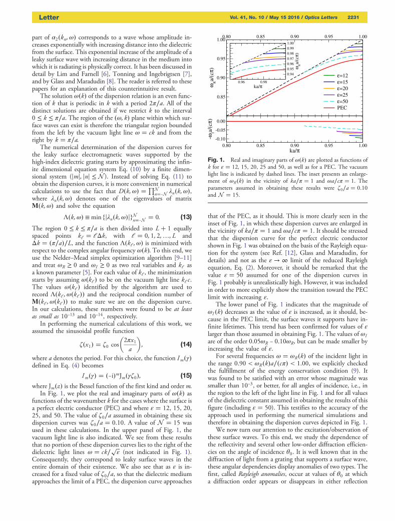
where Jm�z� is the Bessel function of the first kind and order m.In Fig. 1, we plot the real and imaginary parts of ω�k� as
functions of the wavenumber k for the cases where the surface isa perfect electric conductor (PEC) and where ε � 12, 15, 20,25, and 50. The value of ζ0∕a assumed in obtaining these sixdispersion curves was ζ0∕a � 0.10. A value of N � 15 wasused in these calculations. In the upper panel of Fig. 1, thevacuum light line is also indicated. We see from these resultsthat no portion of these dispersion curves lies to the right of thedielectric light lines ω � ck∕
ffiffiffiε
p(not indicated in Fig. 1).
Consequently, they correspond to leaky surface waves in theentire domain of their existence. We also see that as ε is in-creased for a fixed value of ζ0∕a, so that the dielectric mediumapproaches the limit of a PEC, the dispersion curve approaches
that of the PEC, as it should. This is more clearly seen in theinset of Fig. 1, in which these dispersion curves are enlarged inthe vicinity of ka∕π � 1 and ωa∕cπ � 1. It should be stressedthat the dispersion curve for the perfect electric conductorshown in Fig. 1 was obtained on the basis of the Rayleigh equa-tion for the system (see Ref. [12], Glass and Maradudin, fordetails) and not as the ε → ∞ limit of the reduced Rayleighequation, Eq. (2). Moreover, it should be remarked that thevalue ε � 50 assumed for one of the dispersion curves inFig. 1 probably is unrealistically high. However, it was includedin order to more explicitly show the transition toward the PEClimit with increasing ε.
The lower panel of Fig. 1 indicates that the magnitude ofωI �k� decreases as the value of ε is increased, as it should, be-cause in the PEC limit, the surface waves it supports have in-finite lifetimes. This trend has been confirmed for values of εlarger than those assumed in obtaining Fig. 1. The values of ωIare of the order 0.05ωR − 0.10ωR, but can be made smaller byincreasing the value of ε.
For several frequencies ω � ωR�k� of the incident light inthe range 0.90 < ωR�k�a∕�cπ� < 1.00, we explicitly checkedthe fulfillment of the energy conservation condition (9). Itwas found to be satisfied with an error whose magnitude wassmaller than 10−3, or better, for all angles of incidence, i.e., inthe region to the left of the light line in Fig. 1 and for all valuesof the dielectric constant assumed in obtaining the results of thisfigure (including ε � 50). This testifies to the accuracy of theapproach used in performing the numerical simulations andtherefore in obtaining the dispersion curves depicted in Fig. 1.
We now turn our attention to the excitation/observation ofthese surface waves. To this end, we study the dependence ofthe reflectivity and several other low-order diffraction efficien-cies on the angle of incidence θ0. It is well known that in thediffraction of light from a grating that supports a surface wave,these angular dependencies display anomalies of two types. Thefirst, called Rayleigh anomalies, occur at values of θ0 at whicha diffraction order appears or disappears in either reflection
Fig. 1. Real and imaginary parts of ω�k� are plotted as functions ofk for ε � 12, 15, 20, 25 and 50, as well as for a PEC. The vacuumlight line is indicated by dashed lines. The inset presents an enlarge-ment of ωR�k� in the vicinity of ka∕π � 1 and ωa∕cπ � 1. Theparameters assumed in obtaining these results were ζ0∕a � 0.10and N � 15.
Letter Vol. 41, No. 10 / May 15 2016 / Optics Letters 2231

(ϵ � ε1) or transmission (ϵ � ε2). These angles are obtainedfrom the relation
sin θ0 � �ffiffiffiffiffiϵ
ε1
r−2mffiffiffiffiffiε1
p cπωa
; (16)
where ω is the frequency of the incident light and m is an in-teger. The second type of anomaly, called a Wood anomaly, oc-curs at angles of incidence at which the surface waves are excitedthrough the grating by the incident light. The values of θ0 atwhich these anomalies occur are obtained from the relation
sin θ0 �1ffiffiffiffiffiε1
p cπωa
��ksw�ω�
aπ− 2m
�: (17)
In this expression, ksw�ω� is the wavenumber of the surfacewave at the frequency ω of the incident light in the region0 < ksw�ω� < π∕a, and m is an integer. Equations (16) and(17) predict that the angles of incidence at which Rayleighanomalies in transmission and the angles at which Woodanomalies occur coincide when the frequency ω of the incidentlight is that of a point on the vacuum light line when ε2 � 1.
In calculating the angular dependencies of the diffractionefficiencies e�s�m , we have assumed that the medium of incidenceis the high-index dielectric material and vacuum is the mediumof transmission, as this is a more favorable geometry for theobservation of these anomalies. In these calculations, thebranch cut defining the square root in αj�k;ω� was taken alongthe negative real axis, and ω and k were real. In solving Eq. (2),we have assumed either (i) ε1 � 15 or (ii) ε1 � 20 and ε2 � 1.For the wavenumber of the surface waves, we assumedksw�ω�π∕a � 0.9908, which corresponds to a frequency ofthe incident light of (i) ωa∕�cπ� � 0.9808 and (ii) ωa∕�cπ� � 0.9733, respectively. For these frequencies, leakysurface waves are predicted to exist for ksw�ω� and complex
frequency ωR − iωI, where ωR � ω and (i) ωI a∕�cπ� �8.2770 × 10⁻² and (ii) ωI a∕�cπ� � 7.1480 × 10⁻² (see Fig. 1).According to Eq. (17), their existence, for instance, gives rise toWood anomalies at angles (i) θ0 � 15.12°, 15.41°; and(ii) 43.40°, 43.74°. Moreover, Eq. (16) predicts Rayleighanomalies at (i) θ0 � 14.96°, 15.56°; and (ii) θ0 � 43.40°,43.74°. Observe that these anomalies are spread over a fairlynarrow angular interval of width smaller than 1°; this is a con-sequence of the dispersion relation for the leaky surface wavesbeing close to the vacuum light line. Additional anomalies arepredicted by Eqs. (16) and (17), but they are not discussedhere. The values of the remaining parameters assumed in thesecalculations were ζ0∕a � 0.10 and N � 15. In these calcula-tions, unitarity was checked and was found to be satisfied withan error no larger than 10−3.
In Fig. 2, we have plotted the dependence of e�s�m on θ0 forthe reflectivity, m � 0, for m � −1, 1, −2, and −3, and for thetwo values of ε1 considered. The agreement between the pre-dicted and observed angles at which Rayleigh anomalies occuris excellent. For the Wood anomalies, the agreement is fair. Webelieve that this is due to the predicted angular positions of theWood anomalies being determined from the real part of thesurface wave frequency. The imaginary part of the frequency,which is taken into account in the calculation of the diffractionefficiencies, shifts the position of a Wood anomaly and broad-ens it. The existence of the Wood anomalies demonstrates thatit is possible to excite the leaky surface wave with an incidentplane wave. Excitation of this wave in the Otto-attenuated,total reflection geometry is also being investigated.
Thus, by a simple calculation, we have shown in this Letterthat a periodically corrugated interface between vacuum and ahigh-index dielectric medium supports a long-lived p-polarizedleaky surface electromagnetic wave. This result could be appliedto gratings fabricated on such high-index dielectric materials asSnO2 (ε � 9.86 [13]), Al0.6Ga0.4As (ε � 10.24 [14]), silicon(ε � 12), and germanium (ε � 16). These waves could beuseful in the fabrication of surface electromagnetic wave-baseddevices in contexts where a metallic substrate is not suitable,e.g., in an oxidizing atmosphere.
Funding. Research Council of Norway (216699).
REFERENCES
1. F. Yang, J. R. Sambles, and G. W. Bradberry, Phys. Rev. B 44, 5855(1991).
2. J. B. Pendry, L. Martn-Moreno, and F. J. Garca-Vidal, Science 305,847 (2004).
3. G. Naik, J. Kim, N. Kinsey, and A. Boltasseva,Modern Plasmonics, A. A.Maradudin, J. R. Sambles, and W. L. Barnes, eds. (Elsevier, 2014),pp. 189–221.
4. A. A. Maradudin, J. Opt. Soc. Am. 73, 759 (1983).5. A. A. Maradudin, I. Simonsen, J. Polanco, and R. M. Fitzgerald, J. Opt.
18, 024004 (2016).6. T. C. Lim and G. W. Farnell, J. Acoust. Soc. Am. 45, 845 (1969).7. K. A. Ingebrigtsen and A. Tonning, Phys. Rev. 184, 942 (1969).8. N. E. Glass and A. A. Maradudin, J. Appl. Phys. 54, 796 (1983).9. J. A. Nelder and R. Mead, Comput. J. 7, 308 (1965).10. R. O’Neill, Appl. Statist. 20, 338 (1971).11. J. C. Lagarias, J. A. Reeds, M. H. Wright, and P. E. Wright, Soc. Ind.
Appl. Math. J. Optim. 9, 112 (1998).12. N. E. Glass and A. A. Maradudin, Electron. Lett. 17, 773 (1981).13. H. J. van Daal, J. Appl. Phys. 39, 4467 (1968).14. M. L. Y. Huang, Y. Zhou, and C. J. Chang-Hasnain, Nat. Photonics 1,
119 (2007).
0.6
0.8
0.05
0.10
0.1
0.2
D
iffr
acti
on e
ffic
iency;
em(s
)
RayleighWood
14 15 16 17θ0 [deg]
0.05
0.10
0.15
0.6
0.8
0.15
0.30
0.020
0.040
0.060
42 43 44 45θ0 [deg]
0.08
0.12
0.16
0.20
m = 0
m = -1
m = 1
m = -2
m = -3
ε1 = 15 ε
1 = 20
Fig. 2. Diffraction efficiencies in reflection, e�s�m , as functions of theangle of incidence θ0 for ε1 � 15 (left column), ε1 � 20 (right col-umn), and ε2 � 1. The remaining parameters are given in the text.The angular positions of some of the Rayleigh and Wood anomaliesare indicated as dash-dotted and dashed lines, respectively.
2232 Vol. 41, No. 10 / May 15 2016 / Optics Letters Letter