Embed Size (px)
Citation preview

Leak Monitoring Systemsfor double-walled piping
Technical details

11.04.2013 – T – page 2
Leak monitoring systems LDS
Subject to technical changes.
Contents
8.0 Contents
8.1 Leak monitoring for double-walled piping8.100 System description8.105 Overview of leak detectors8.110 Leak monitoring Online Diagnosis LOD8.120 Maximum monitoring length – double-walled piping with vacuum leak monitoring8.130 Maximum monitoring length – double-walled piping with positive pressure leak monitoring
8.20 Leak monitoring with vacuum leak detector Type VLR 410/E8.200 System description8.210 Technical data8.213 Construction8.214 Laying in one line up to max. 25 bar8.216 Laying in one line up to max. 25 bar with additional measuring unit ZD 4108.217 Laying in two or in multiple lines up to max. 25 bar8.218 Laying in multiple lines with distributor block up to max. 25 bar
8.23 Leak monitoring with vacuum leak detector Type VLX 330/A-Ex8.230 System description, technical data8.232 Construction8.233 Laying in one line up to max. 10 bar8.236 Laying in two or in multiple lines up to max. 10 bar8.237 Laying in multiple lines with distributor block up to max. 10 bar
8.30 Leak monitoring with positive pressure leak detector Type DLR-G ...8.300 System description8.301 Switching pressures8.302 Overview, technical data, construction8.304 One-line system – horizontal and vertical laying8.305 Two and multiple line systems – horizontal and vertical laying
8.32 Leak monitoring with positive pressure leak detector Type DLR-P 2.08.320 System description8.322 Overview, technical data, construction8.324 Horizontal laying with gradient to the tank
8.26 Fittings for leak monitoring, general8.260 Insulator,flangeadaptertohose,testvalves8.261 Measuringbranch,manualflangingtool
8.25 Fittings for vacuum leak monitoring8.251 Solenoid valve, additional measuring unit ZD 410, detonation guard, distributor block
8.34 Fittings for positive pressure leak monitoring8.342 Fittings for positive pressure leak detector Type DLR-G ...8.343 Fittings for positive pressure leak detector Type DLR-P 2.0 and SECON®-X monitoring sleeve
8.0

11.04.2013 – T – page 3
Leak monitoring systems LDS
Subject to technical changes.
Contents
8.0
Leak monitoring: Checking the plant8.270 Procedure8.271 Procedure
8.272 Type VLR 410/E and VLX 330/A-Ex – General information8.273 Type VLR 410/E and VLX 330/A-Ex – Checking the plant8.274 Type VLR 410/E and VLX 330/A-Ex – Test report
8.362 Type DLR-G ... and DLR-P 2.0 – General information8.363 Type DLR-G ... and DLR-P 2.0 – Checking the plant8.364 Type DLR-G ... and DLR-P 2.0 – Test report
8.380 Locating the leak inner and outer pipe; procedure

11.04.2013 – T – page 4
Leak monitoring systems LDS
Subject to technical changes.
8.100
Leak monitoring für double-walled pipingSystem description
double-walled piping with positive pressure leak detector
All leak detection equipment/leak detectors in use must comply with the basic criteria laid down for construction and testing standards. All such preconditions which could have a bearing on the functional and operative safety of the system must therefore be observed.
It therefore goes without saying that the conditions for operative use havebeentestedbythecompetentauthoritiesandclearlydefinedandset down in the documents of approval issued by them.
Double-walled piping with leak monitoring is an approved leak detec-tion equipment/leak detector system.
The advantages of the system
Using double-walled FLEXWELL® Safety Pipe with leak monitoring offers, besides a high degree of operative safety, substantial economic advantages:
- the entire system can be easily and simply monitored at any time without interrupting operations- requirements such as e.g. pressure/volume measurements, pressure tests or route surveys can be dispensed with- when a leak occurs, operations can normally be continued without interruption; repairs can be planned.- remote monitoring (LOD) of all operating parameters is possible (24/7).
double-walled piping with vacuum leak detector
The leak monitoring
Double-walled piping is permanently monitored using pneumatic leak detecting devices. These regulate the monitoring pressure in the surveillance space and register any changes of pressure which may occur. The surveillance space prevents uncontrolled spillages of the transport medium when leaks occur. The surveillance space must be so constructed that the functioning and operative security of the leak monitoring system (the leak detector) is assured at all times. The size if the surveillance space for each leak detector is limited to 10 m3 acc. to DIN EN 13160.
If the pipe is damaged the alarm is given by acoustic and optical signals.
Definition of leak detection equipment/leak detector
“Leak detection equipment/leak detector” according to the cur-rently valid regulations refers to a device which automatically and under all operating conditions gives warning of leaks in the walls of double-walledpipinginwhichwaterhazardous(flammableandnon-flammable)fluidsaretransported.Theterm“leakdetectionequipment/leak detector” includes all the equipment necessary for the detection of leaks.
The main components are:- the leak detector/leak monitoring equipment - the connection between the surveillance space and leak detector)- double-walled piping: FLEXWELL® Safety Pipe BRUGG-STAMANT® Safety Pipe SECON®-X Petrol station pipe- the surveillance space - a leak detection medium
The use of this system complies with the most stringent European safety standards (Class 1). Systems of this classgivewarningofaleakaboveorbelowthefluidlevelin a double-walled protective system. They are construct-ed on the principles of absolute safety and ensure that spillages of products into the environment cannot occur.
Leak detector
We distinguish two types of differential pressure leak detection equipment: Leak surveillance to detect leaks in double-walled piping on the vacuum principle and on the positive pressure principle.
Approval/suitability
DLR-G ...

11.04.2013 – T – page 5
Leak monitoring systems LDS
Subject to technical changes.
8.105
Leak monitoring für double-walled pipingOverview of leak detectors
Type of leak detector VLR 410/E VLX 330/A-Ex DLR-G ... DLR-P ...
Type of pipe
FLEXWELL®SafetyPipe • • • •
BRUGG-STAMANT®SafetyPipe • • • –
SECON®-XPetrolStationPipe • • – •
Area for installation
Dryandfrost-freearea • • • •
• • • •
– • – –
Flashpoint of transport medium
<55°C – • • •
>55°C • • • •
Max. pipe length see Workshee LDS 8.120 LDS 8.120 LDS 8.130 LDS 8.130
Max. operating pressure 25 bar 10 bar 22 bar 1 bar
Potential-freerelay • • • •
RemotemonitoringoptionLOD • •
Dimensions of housing (BxHxT) in mm 217x266x110 300x200x160 217x266x110 127x266x110
dimensions detector unit 200x120x90
Additional criteria for selection
DLR-G ...VLR ... VLX 330/A-ExDLR-P ...Detector unit
Compact, uncom-
plicated leak detec-
tor for consumer
heating oil plants
Leak detector for
flammablemediawith
minimum mainte-
nance
Electronic leak
detector for
all pressure stages
Reliable leak
detector for
petrol stations
low operating
pressu
Please note
- monitorable pipe lengths acc. to Worksheets LDS 8.120 and LDS 8.130- observe the effective area as well as the Ex zones- Queries refer to all the piping to be monitored and all media transported- the permissible operating and surveillance space pressures of the various pipe systems must be considered
Type vacuum leak monitoring positive pressure leak monitoring
max. pressure max. pressure max pressure max. pressure
inner pipe surveillance space inner pipe surveillance space
bar bar bar bar
FLEXWELL® Safety Pipe (all sizes) 25 –0.7 22 25
SECON®-X 25 3.5 –0.7 2.0 3.5
SECON®-X 40 3.5 –0.7 2.0 3.5
SECON®-X 50 3.5 –0.7 2.0 3.5
SECON®-X 100 3.5 –0.7 1.0 2.5
BRUGG-STAMANT® Safety Pipe acc. to project on request / References up to 400 °C and 250 bar
Special piping acc. to project on request
Monitorable pressures

11.04.2013 – T – page 6
Leak monitoring systems LDS
Subject to technical changes.
8.110
Leak detector for double-walled pipingLeak monitoring Online Diagnosis LOD
According to VAUwS the operator of a plant with water-hazardous substances is obliged to provide evidence that the plant is leak-proof and to check the functioning of the safety precautions (leak detector) regularly. In order to optimise these function checks, BRUGG Rohr-systeme GmbH offers a remote monitoring system, LOD.
What is LOD?
LeakmonitoringOnlineDiagnosis,LOD,isasystemwhichforthefirsttime realizes the safe and continuous remote monitoring of a leak detector. Each and every operating parameter is recorded around the clock (24/7), communicated automatically once every 24 hours by mobile telephony to the LOD server where it is analysed. That means that the correct operational functioning of the leak detector is checked every single day.
How does LOD work?
Any alarm is immediately communicated to the system when it occurs and leads directly and automatically to an email or text message being sent to the addresses you have supplied. All alarm messages received are registered by the LOD system, repeated at regular intervals and onlydeletedafterthecauseofthealarmhasbeenrectifiedonsite.In this, LOD not only checks all functions of the leak detector but transmits the current pressure in the monitoring system as well as the leak status of the entire plant. This provides a hitherto unattained degree of certainty that the alarm signal will be relayed onwards and the necessary reaction ensured.
Technical details and installation of LOD
The leak detector comes equipped ex works with a pre-installed data transfer module (DTM) and a powerful externally visible rod aerial. The individual DTM is connected to the electronic system of the leak detectorandloggedintotheLODviaaserialnumberwhichidentifiesit clearly. For installations in areas which have a poor telephony signal, an aerial extension including an angled support is available.
Overview of the data transmitted
- daily report checking on the operation and functioning of the leak detector- r eal-time status of pressure in the system; alarm signal if pressure drops- leak tightness of the entire system consisting of the leak detector and the connected surveillance space- frequency of pump runs and overall running time of pump for ordering service checks - responsiveness check of internal sensor (probe or ZD)- status of an additional digital sensor (if connected to DTM)- output value of an additional analogue 4 – 20 mbar sensor (if connected to DTM), e.g. readout of residual pressure in gas bottles
Advantages of the system
- it is no longer possible to overlook alarm signals or ignore incoming alarms, alarm equipment can no longer be manipulated- can also be used for installations in remote locations which are not easily accessible and are only seldom visited, for petrol stations without attendants, standby power supply systems- safe from manipulation- maximum possible operating safety- maintenance checks can be optimally planned through automatic messages to identify service needs- minimal plant downtime ensured
Availability of LOD
LOD is available in all three DACH countries (Germany, Austria, Switzerland/black coloured). Availability over the rest of Europe (grey coloured) is under preparation.

11.04.2013 – T – page 7
Leak monitoring systems LDS
Subject to technical changes.
Maximum monitoring length
BasisZG-LAGR principles of approval for leak monitoring equipment for double-walled piping
Determining the maximum monitorable pipe lengthHalfthealarm-triggeringpressureloss„on“in[mbar]oftheleakdetectorused,withcertificateofsuitabilityforapprovalbythebuildingau-thorities from the DIBt (Deutschen Institut for Bautechnik), divided by the pressure loss per metre in the surveillance space gives the maximal monitorable pipe length.
L max. = alarm-triggering pressure loss „on“ [mbar] 2 · pressure loss [mbar/m]
ExampleType of laying single lineAlarm-triggering pressure loss „on“ 410 mbarHalf alarm-triggering pressure loss 205 mbarType of pipe FSR 60/83max. monitorable pipe length L max. ~ 460 m
285
205
250
165
alar
m-t
rigge
ring
pres
sure
/ 2
[mba
r]
Double-walled piping with vacuum leak monitoring
Meter [m]
1000
500
100
10
1
2
2 3 46 67 78 89 950 500100 1000 2000
FSR 60/83
FSR 75/107
FSR 13/25 und SEC 100
FSR 98/134
FSR 127/175
FSR 30/48
SEC 40SEC 50
FSR 39/60
FSR 48/71 pressure loss / m
~ 460
8.120
Diagram for horizontal laying of double-walled piping FLEXWELL® Safety Pipe (FSR) and SECON®-X (SEC)
SEC 25

11.04.2013 – T – page 8
Leak monitoring systems LDS
Subject to technical changes.
8.130
Maximum monitoring length
BasisZG-LAGR principles of approval for leak monitoring equipment for double-walled piping
Determining the maximum monitorable pipe lengthHalfthealarm-triggeringpressureloss„on“in[mbar]oftheleakdetectorused,withcertificateofsuitabilityforapprovalbythebuildingauthorities from the DIBt (Deutschen Institut for Bautechnik), divided by the pressure loss per metre in the surveillance space gives the maximal monitorable pipe length.
L max. = differential pressure in surveillance space [mbar] 2 · pressure loss [mbar/m]
ExampleType of laying single lineTransport pressure in operating pipe 5 barMonitoring pressure in surveillance space 7 barAlarm-triggering pressure rise „on“ 6 barDifferential pressure in the surveillance space 1 barAlarm-triggering pressure rise „on“ 6 bar gives 1000 mbar differential pressureHalf alarm-triggering pressure rise 500 mbarType of pipe FSR 60/83max. monitorable pipe length L max. 1100 m
Meter [m]
1000
500
100
10
1
2
diffe
rent
ial p
ress
ure
in s
urve
illan
ce s
pace
/ 2
[mba
r]
2 3 46 67 78 89 950 500100 1000 2000
FSR 60/83
FSR 75/107
FSR 13/25
FSR 98/134SEC 100
FSR 127/175
FSR 30/48
SEC 40FSR 39/60
FSR 48/71
SEC 50SEC 25
pessoure loss / m
Double-walled piping with positive pressure leak monitoring
1100
Diagram for horizontal laying of double-walled piping FLEXWELL® Safety Pipe (FSR) and SECON®-X (SEC)

11.04.2013 – T – page 9
Leak monitoring systems LDS
Subject to technical changes.
8.200
Vacuum leak detector Type VLR 410/E
Leak monitoring on the vacuum principle
The vacuum leak detector Type VLR is suitable and approved for the monitoring of double-walledpipingusedfortransportingwater-hazardousflammablesubstanceswithaflashpoint> 55 °C (e.g. heating oil, diesel fuel, water-glycol mixture, AD Blue, ...).
Versions
VLR 410/E: max. operating pressure in the inner pipe 25 bar (a leakage probe or a solenoid valve or both can be connected in addition).
Alarm-triggering values
VLR 410/E: on > 410 mbar
Functioning principle
The vacuum pump installed in the leak detector creates a partial vacuum in the surveillance space. This partial vacuum is measured by a pressure sensor. Through monitoring the vacuum, leaks are therefore automatically detected.
In the event of a drop in the partial vacuum below the lower value of the monitoring partial vacuum (pressure rise) due to a leak, an optical and acoustic alarm is triggered. Minimal, unavoidable permeability (not leaks) are regulated automatically by the leak detector without triggering the alarm if they lie between the upper and lower values of the monitoring partial vacuum. Subsequent evacuation is carried out by the vacuum pump in the leak detector. In every case in which the alarm is triggered by the VLR410/E the vacuum pump is automatically switched off. It can only be switched on again by throwing the toggle switch “Operation”.
Technical basis Thescopeofapplicationoftheleakdetectiondevicemustbelimitedtofixedmaximumpipelengths due to the laws of physics. These depend on upper and lower points of reference and on the type of lying of the double-walled safety piping. The types of laying are illustrated in the Worksheets LDS 8.214 ff.
Tips for installation
The leak detector may not be installed in areas where there is a danger of explosions. Wherever possible, the leak detector should be mounted inside an enclosed dry room. If it is installed outside enclosed rooms, the leak detector must be mounted in a weatherproof metal housing.
Installation/commencement of operations/operation/function testing
Detailed descriptions can be seen from the approval documentation of the VLR leak detector. The conditions set out in the approval for double-walled piping and the VLR leak detector must be complied with.
Example leak monitoring diagramVacuum
System description
VLR ...
VT
KP

11.04.2013 – T – page 10
Leak monitoring systems LDS
Subject to technical changes.
8.210
Vacuum leak detector Type VLR 410/ETechnical data
Overview leak detector Type VLR 410/E
Applications
Monitorable pipe length
Operating pressure
Installation area
Installation in the open/
in damp rooms
Housing dimensions
Fittings
Electrical data
water-hazardousfluidswithaflashpoint>55°C,withouttheoccurrenceofexplosivevapour-air
mixtures.Fromflashpoint<55°C:VLX...inExversion
L max = max. monitorable pipe length acc. to laying procedure
(see Worksheet LDS 8.120, for underground and surface-laid pipes.
up to max. 25 bar VLR 410/E (with operating pressure from 5 bar a solenoid valve must be used)
wherever possible, install inside an enclosed, dry room with no access for unauthorized personnel.
Installation in the open inside a suitable metal housing and not in areas where there is a danger of
explosions.
inside a suitable metal housing, depending on the requirements – optical and acoustic signal
Height: 210 mm, width: 265 mm, depth: 110 mm
Insulatingpiecewithflangedscrewconnectiontoseparatethemetalconnectionin
earthed installations acc. to TRbF 521.
Rated input (without external signal) 230 V~ – 50 Hz – 50 W
Switching contact load, connector block AS (5 and 6) 230 V~ – 50 Hz – 200 VA
Switching contact load, potential-free contacts, connector block 11 to 12 max. 230 V~ – 50 Hz – 5 A
min. 6 V/10 mA
External fuse protection of the leak detector max. 10 A
Overvoltage category 2

11.04.2013 – T – page 11
Leak monitoring systems LDS
Subject to technical changes.
8.213
Vacuum leak detector Type VLR 410/EConstruction
Suction pipe and measuring lead of the leak detectors are connected by means of a screwed T-piece (crosspoint KP) and connected to the connectionfittingAVbyameasuringbranchMA.
BV three-way stopcock suction pipeGD three-way stopcock measuring leadFL fluidbarrierA signal lamp „Alarm“A1 signal lamp Alarm 2 (leak probe)B signal lamp „Operations“TA Switch-key acoustic signal KS Switch-key commence operationsK CrosspointAV Connectionfitting
Connected to a single-line system (Worksheet LDS 8.214 and 8.216) Multiple-line system with distributor block (Worksheet LDS 8.218)
Connected to a multiple-line system (Worksheet LDS 8.217)
When several double-walled piping lines are connected, the individual surveillance spaces are directly connected via the distributor block or switched in-line. The suction pipe is connected at the front, the measuring lead at the end of the series. The surveillance spaces of the piping lines are connected together. All connection and connectionfittingsareconnectedtotheconnectionfittingAVbymeans of a measuring branch MA.
BVGD
FL
measuring lead
A1
B
TAKS
shut
open
suction pipe
Exhaust tube
A
measuring leadsuction pipe
MA
MA
AV
AV
KP
MA
AV
VLR ...
Construction vacuum leak detector Type VLR 410/EArticle No. 829 424 09

11.04.2013 – T – page 12
Leak monitoring systems LDS
Subject to technical changes.
GD
MA
AV
KP
BVGD
shut
opn
AV
AV
PV
PV
P < 5 bar
max
. 3.5
m
max
. 3.0
m
8.214
Vacuum leak detector Type VLR 410/ELaying in a single line up to max. 25 bar
MA Mesauring branchAV connectionfittingPV test valveKP cross pointPB transport pressure in inner pipeMV solenoid valveFL fluidbarrier
Connecting the leak detector to the surveillance spaceOf the double-walled safety pipe (Worksheet LDS 8.213)
A test valve must be installed at the far end of the pipe. The low point(s) must not exceed a depth of 3.5 m. The piping can have further high or low points as long as the sum of the high and low points doues not exceed 3.5 m.
At a PB > 5 bar up to max. 25 bar a solenoid valve MV must be installed between the crosspoint KP and the measuring branch MA.
The solenoid valve protects the leak detector from non-permissible high pressures. The solenoid valve is monitored electronically so that a failure of the solenoid valve triggers the alarm.
MA
AV
MV
FL
MAAV
PV
AV
KP
max
. 3.0
m
max
. 3.5
m
max
. 250
m BV zu
open

11.04.2013 – T – page 13
Leak monitoring systems LDS
Subject to technical changes.
8.216
Vacuum leak detector Type VLR 410/ELaying in one line up to max. 25 bar with additional measuring unit ZD 410
Max. monitorable
pipe length L max.
for all sizes: 500 m
At a PB > 5 bar up to max. 25 bar a solenoid valve MV must be installed between the crosspoint KP and the measuring branch MA.
The solenoid valve protects the leak detector from non-permissible high pressures. The solenoid valve is monitored electronically so that a failure of the solenoid valve triggers the alarm.
Ifthemaximummonitorablelengthacc.toWorksheetLDS8.120isnotsufficientforanindividualcasethe additional measuring unit ZD 410 must be installed.
Connecting the leak detector to the surveillance spaceof the double-walled safety pipe (Worksheet LDS 8.213)
The leak detector is connected as shown in the illustration in Worksheet LDS 8.213. An additional measuring unit Type ZD 410 is installed at the other end of the pipe using the same connection method. The additional measuring unit Type ZD 410 is electrically connected to the leak detector VLR10/E.
KP
MA
AVAV
L max < = 500 m
h max. = 3.0 m
ZD 410
closed
open
MA
h1 < = 10 m
SL
PD
MA
AV
MV
MA Measuring branchA connectionfittingKP crosspointFL fluidbarrierPD three-way stopcock
FL
ZD 410 additional measuring unitPB transport pressure in inner pipeMV solenoid valveSL eletric control lead type NYY 3 x 1,52
BV GDshut
open
max
. 3.5
m

11.04.2013 – T – page 14
Leak monitoring systems LDS
Subject to technical changes.
8.217
Vacuum leak detector Type VLR 410/ELaying in two or multiple lines up to max. 25 bar
Max. monitorable
pipe length L max.
Sum of all ind. lengths
for FLEXWELL ®
Safety Pipe –
all types: up to 500 m
At a maximum pipe
length > 500 m see
Worksheet LDS 8.120
At a PB > 5 bar up to max. 25 bar a solenoid valve MV 115 V must be installed in both the suction pipe and the measuring lead.
The solenoid valves protect the leak detector from non-permissible high pressures. The solenoid valves are monitored electronically so that a failure of a solenoid valve triggers the alarm.
Connecting the leak detector to the surveillance spaceof the double-walled safety pipe (Worksheet LDS 8.213)
The geodetic difference in height between the lowest point of the piping and the leak detector must not exceed 3.5 m. The depth of 3.5 m is the limiting line between the “highest” and “lowest” low points.
MA measuring branchAV connectionfittingMV solenoid valveBV ventilation valveGD three-way stopcockFL fluidbarrier
measuringlead
suction pipe
MA
AV
MV1 MV2
MA
AV
BV GD
FL
measuringlead
shut
open
suction pipe
exhaust tube
MA
AV MA
AV
MA
AVMA
AV
VÜR 1
VÜR 2
max
. 3.5
m
MA
AV
AV MA
AV
MA
AV
VÜR 1
VÜR 2
VÜR 3
VÜR 4
measuringlead
suction pipe
MA
AV
MA
AV
MA
AV
MA
AV
max
. 3.5
m
FL

11.04.2013 – T – page 15
Leak monitoring systems LDS
Subject to technical changes.
8.218
Vacuum leak detector Type VLR 410/ELaying in multiple lines with distributor block up to max. 25 bar
Connection of the leak detector to the distributor block (Worksheet LDS 8.213)
The individual surveillance spaces of the double-walled piping lines are connected using the measuring branch MA to the outlets of the distributor block. When laying in multiple lines, the double-walled piping may have high and low points as described in Worksheet LDS 8.214 for laying in a single line, as long as the sum of the high and low points does not exceed 3.5 m.
At PB > 5 bar up to max. 25 bar a solenoid valve MV must be installed between the crosspoint KP and the connection to the distributor block VT.
The solenoid valve protects the leak detector from non-permissible high pressures. The solenoid valve is monitored electronically so that a failure of the solenoid valve triggers the alarm.
MA measuring branchAV connectionfittingPV test valveKP crosspointMV solenoid valveBV ventilation valveGD three-way stopcockVT distributor blockFL fluidbarrier
VT
MV
MA
AV
MA
AV
MA
AV
FLFLFL
KP
VTPV
PV
PV
AV
AV
AVm
ax. 3
.5 m
BV GDshut
open

11.04.2013 – T – page 16
Leak monitoring systems LDS
Subject to technical changes.
8.230
Vacuum leak detector Type VLX 330/A-ExSystem description, technical data
Type VLX 330/A-Ex, version with partial protection from explosions
The vacuum leak detector Type VLX 330/A-Ex is suitable and approved for monitoring double-walled safety piping throughwhichthefollowingfluidsaretransported:
• Flashpoint<55°C• water-hazardous,flammablefluidswithapossibleoccurrenceofpotentiallyexplosivevapour-airmixturesassignable to explosion categories IIA or IIB3 and temperature category T1 to T3 (e.g., petrol, motor fuels in general, ...)
Double-walled components may be integrated into the piping. Approved for a max. operating pressure in the operational pipe Type VLX 330/A-Ex ... up to max. 10 barType VLX 330/A-MV-Ex up to max. 25 bar
Installation/commencement of operations/operation/function testing
Thescopeofapplicationoftheleakdetectiondevicemustbelimitedtofixedmaximumpipelengthsduetothelawsof physics. These depend on upper and lower points of reference and on the type of lying of the double-walled safety piping. The types of laying are illustrated in the Worksheets LDS 8.233 ff.
The conditions set out in the approval for double-walled piping and for the leak detector must be complied with.
Overview of leak detector VLX 330/A-Ex
Applications
Operating pressure in
inner pipe
Monitorable pipe length
Installation area
Installation
Housing
Fittings
Electrical data
Water-hazardousfluidswithaflashpoint<55°C,withapossibleoccurrenceofpotentiallyexplosive
vapour-air mixtures assignable to explosion categories IIA or IIB3 and temperature category T1 to
T3 (e.g., petrol, motor fuels in general, ...)
VLX 330/A-Ex: max. 10 bar
VLX 330/A-MV-Ex: max. 25 bar
L max = monitorable pipe length acc. to Worksheet LDS 8.120
for underground and surface-laid pipes
acc. to installation instructions and description of leak detector VLX 330/A-Ex
see description of leak detectors VLX 330/Ex and VLX 330/A-Ex
VLX 330/A-Ex comprises a control unit and the working device
fittingssetoutintheprogrammefortheleakdetectorandthedouble-walledpiping
Rated input (without external signal) 230 V~ – 50 Hz – 50 W
Switching contact load, potential-free contacts max. 230 V~ – 50 Hz – 5 A
Connector block 21 - 24 min. 6 V/10 mA
External fuse predection of the leak detector max. 10 A
Overvoltage category 2
On request, Type VLX 330/Ex can be delivered in a completely explosion-protected version.

11.04.2013 – T – page 17
Leak monitoring systems LDS
Subject to technical changes.
8.232
Vacuum leak detector Type VLX 330/A-ExConstruction
Construction vacuum leak detector Type VLX 330/A-ExArticle No. 829 423 98
BV screwedflangeconnectionGD three-way stopcock measuring lead/suction pipeDS detonation protectionFL fluidbarrierDG pressure compensating vessel
Construction vacuum leak detector Type VLX 330/A-MV-Ex (available on request)
In the Type VLX 330/A-MV-Ex an additional solenoid valve is integrated into the leak detector.
If the working device is used in a „Non-Ex area“, the exhaust tube must be relocated to an Ex area of Zone I.
BV
GD
FL
Measuring lead
suction pipe
Exhaust tube
KP
DS
VLX 330/A-Ex
working unit
signal unit
Ex
Ex
Ex
Construction vacuum leak detector Type VLX 330/Ex Article No. 829 424 10(available on request)
BV screwedflangeconnectionGD three-way stopcock measuring lead/suction pipeDS detonation protectionFL fluidbarrierKP crosspointDG pressure compensating vessel
BV
GD
FL
Measuring leadsuction pipe
Exhaust tube
KP
DS
VLX 330/Ex
DG
Ex
DG

11.04.2013 – T – page 18
Leak monitoring systems LDS
Subject to technical changes.
KP
8.233
Connecting the leak detector to the surveillance spaceof the double-walled piping (Worksheet LDS 8.232)
A test valve must be installed at the far end of the pipe. The low point(s) must not exceed adepth of 3.5 m. The piping can have further high or low points as long as the sum of the high and low points does not exceed 3.5 m..
Vacuum leak detector Type VLX 330/A-ExLaying in one line up to max. 10 bar
MA measuring branchDS detonation protection (only if Ex danger)AV connectionfittingPV test valveKP crosspoint
MA
AV
AV
AV
PV
PV
max
. 3.0
m
max
. 3.5
m
max
. 100
m
DS
MAAV
PV
AV
KP
max
. 3.0
m
max
. 3.5
m
DS
BV GDshut
open
BV GDshut
open
DS
DS

11.04.2013 – T – page 19
Leak monitoring systems LDS
Subject to technical changes.
8.236
Vacuum leak detector Type VLX 330/A-ExLaying in two or multiple lines up to max. 10 bar
The geodetic difference in height between the lowest point of the piping and the leak detector must notexceed 3.5 m. The depth of 3.5 m is the limiting line between the “highest” and “lowest” low points.
MA measuring branchDS detonation protectionAV connectionfittingBV ventilation valveGD three-way stopcockFL fluidbarrier
BV GD
FL
Measuring lead
shut
open
suction pipeexhaust
tube
MA
AV MA
AV
MA
AVMA
AV
VÜR 1
VÜR 2
max
. 3.5
m
DS
DS
Max. monitorable
pipe length L max.
Sum of all ind. lengths
for FLEXWELL ®
Safety Pipe –
all types: up to 500 m
At a maximum pipe
length > 500 m see
Worksheet LDS 8.120
MA
AV
MA
AV MA
AV
MA
AV
VÜR 1
VÜR 2
VÜR 3
VÜR 4
Measuring lead
suction pipe
MA
AV
MA
AV
MA
AV
MA
AV
max
. 3.5
m
DS

11.04.2013 – T – page 20
Leak monitoring systems LDS
Subject to technical changes.
MA
AV
MA
AV
MA
AV
FLFLFL
KP
VTPV
PV
PV
AV
AV
AV
8.237
Vacuum leak detector Type VLX 330/A-ExLaying in multiple lines with distributor block up to max. 10 bar
The individual surveillance spaces of the double-walled piping lines are connected using the measuring branch MA to the outlets of the distributor block. When laying in multiple lines, the double-walled piping may have high and low points as described in Worksheet LDS 8.233 for laying in a single line, as long as the sum of the high and low points does not exceed 3.5 m.
MA measuring branchDS detonation protection (only if Ex danger)AV connectionfittingPV test valveVT distributor blockFL fluidbarrierconnectedagainstthereversedirection
max
. 3.5
m
DS
DS
DS
BV GDshut
openDS

11.04.2013 – T – page 21
Leak monitoring systems LDS
Subject to technical changes.
8.300
Positive pressure leak detector Type DLR-G ...System description
The positive pressure leak detector Type: DLR-G... is suitable as per approval for monitoring double-walledpipingthroughwhichwater-hazardousfluidswithaflashpointbelowandabove55 °C is transported.
Functioning principles
The necessary pressure in the surveillance space of the double-walled piping depends on the actual operating pressure in the medium pipe (inner pipe) and is generated- by topping up regulated by pressure changes from a stationary nitrogen pressure reservoir connected continuously to the surveillance space: Operating Mode S(tationary)- from a mobile pressure reservoir which is only connected when the line is put into operation or during a function test: Operating Mode M(obile)
Operating modes S and M can be chosen by adjusting the switch on the board in the leak detector.
The surveillance space is connected with the leak detector by means of the connecting leads. The pressure which builds up is measured by the pressure sensor. If pressure drops to the value set previously for ALARM-ON due to a leak, the optical and acoustic alarm will be triggered.
In operating mode S the monitoring pressure is regulated after putting the system into operation by pressure changes which top up from a stationary nitrogen pressure reservoir which is conti-nuously connected with the surveillance space and equipped with a pressure reducing valve.
In operating mode M the monitoring pressure (TOP-UP OFF) is set just once when the system is put into operation by a pressure reservoir which is not continuously connected. There is no top-up regulated by pressure changes in subsequent operation. Any drop in pressure which reaches the ALARM ON point and triggers the alarm must then be compensated by connecting the pressure reservoir till the previously set TOP-UP OFF level is reached.
The manufacturer of the leak detector stipulates that the leak detector must be undergo a maintenancecheckonceayearonarecurringbasisbyanexpertfirmaccreditedaccordingtoWHG in order to ensure correct functioning and operating safety.
Switching pressures see Table 1 in Worksheet LDS 8.301.
Technical basis
The scope of application of the leak monitoring system is limited by maximum piping lengths. The alarm is triggered by the leak detector at the latest when a pressure which is at least 1.0 bar over the maximum transport pressure of the medium pipe (inner pipe) is reached (see Table 1). The types of laying are illustrated in Worksheets LDS 8.304 and LDS 8.305.
Tips for installation
The leak detector may not be installed in areas where there is a danger of explosions. Wherever possible, the leak detector should be mounted inside an enclosed dry room. If it is installed outside enclosed rooms, the leak detector must be mounted in a weatherproof metal housing.
Installation/commencement of operations/operation/function testing
Detailed descriptions can be seen from the approval documentation of the DLR-G ... leak detec-tor and the Worksheets for the FLEXWELL® piping. The conditions set out in the approval for the double-walled piping and the DLR-G ... leak detector must be complied with.
DLR-G ...
Positive pressure leak monitoringfor horizontal and vertical laying and two- and multiple line systems

11.04.2013 – T – page 22
Leak monitoring systems LDS
Subject to technical changes.
8.301
Positive pressure leak detector Type DLR-G ...Switching pressures
Type PB PAE PPA PUDV11) PPRÜF PDM DM
DLR-G bar bar bar bar bar bar bar
1 pressure 0 > 1 < 2 9.0 ± 0.5 > 3.4 2.5
2 < 1 > 2 < 3 9.0 ± 0.5 > 4.5 3.5
3 < 2 > 3 < 4 9.0 ± 0.5 > 5.6 4.5
4 < 3 > 4 < 5 9.0 ± 0.5 > 6.7 5.5 10
5 < 4 > 5 < 6 9.0 ± 0.5 > 7.8 6.5
6 < 5 > 6 < 7 9.0 ± 0.5 > 8.9 7.5
7 < 6 > 7 < 8 9.0 ± 0.5 > 10 8.5
10 < 9 > 10 < 12 - > 15.4 13
11 < 10 > 11 < 13 - > 16.5 14 16
12 < 11 > 12 < 14 - > 17.6 15
13 < 12 > 13 < 15 - > 18.7 16
14 < 13 > 14 < 16 - > 19.8 17 20
15 < 14 > 15 < 17 - > 20.9 18
16 < 15 > 16 < 18 - > 22.0 19
17 < 16 > 17 < 19 - > 23.1 20
18 < 17 > 18 < 20 - > 24.2 21 22
21 < 20 > 21 < 23 - 25 24
23 < 22 > 23 < 25 - 25 25 25
Tabelle 1: Switching pressures for operating pressures in the medium pipe
PB = Maximum operating pressure in inner pipe (transport pressure + back pressure + pressure due to geodetic height differences)PAE = switching level „Alarm ON“, the alarm is triggered at the latest when this level is reachedPAA = switching level „Alarm OFF“, when this level is exceeded the alarm signal is deleted (PAA = PAE + ~250 mbar with DLR-G 1...7; PAA = PAE + ~500 mbar with DLR-G 10..18)PPA = switching level „Top-Up OFF“ (= set pressure level)PPE = switching level „Top-Up ON“ (PPE = PPA – ~250 mbar with DLR-G 1...7; PPE = PPA – ~500 mbar with DLR-G 10...18)PÜDV1 =triggerpressureofpressurecontrolvalve1(frommonitoringfirm)PPRÜF = minimum testing pressure in surveillance spacePDM = pressure set in pressure reducing valveDM = pressure range set in pressure reducing valve (secondary pressure)
1) The pressure control valve ÜDV1 can be dispensed with if it can be ensured that no pressure increases exceeding the test pressure (e.g. due to warming) can occur in the surveillance space and the pressure to which the pressure reducing valve is set is lower than the test pressure of the surveillance space.

11.04.2013 – T – page 23
Leak monitoring systems LDS
Subject to technical changes.
8.302
Positive pressure leak detector Type DLR-G ...Overview, technical data, construction
Leak detector Type DLR-G ...
Operating mode M – mobile
water-hazardousfluids
underground double-walled piping
ind. pipe length or sum of all pipe lengths
L max = 2000 m
leak detector: 230 V, 50 Hz AC
distributor block 1, 2
potential-free relay contacts „Alarm“
230 V, 2 A – distributor block 11, 12
nitrogen
Wherever possible, install inside an enclosed, dry room with
no access for unauthorized personnel. Installation in areas
where there is a danger of explosions is not permitted.
Nitrogen bottle with pressure reduction valve for operation or
function test, mobile
via potential-free relay
LAZ technically adapted to operating pressure of
doublewalled piping
height width depth
210 mm 265 mm 110 mm
distributor block Type HMB, 2 – 8 connections to
double-walled piping
Insulator Type ET to separate the metal connection
in earthed installations acc. to TRbF 521
Application
Area of use
Monitorable pipe length
Electric connection
Leak detection
Installation area
Generation of
extra pressure
Extra functions
Additional criteria
Housing dimensions
Fittings
Leak detector Type DLR-G ...
Operating mode S – stationary
water-hazardousfluids
underground and surface-laid double-walled piping
ind. pipe length or sum of all pipe lengths
L max = 2000 m
leak detector: 230 V, 50 Hz AC
distributor block 1, 2
potential-free relay contacts „Alarm“
230 V, 2 A – distributor block 11, 12
nitrogen
Wherever possible, install inside an enclosed, dry room with no
access for unauthorized personnel. Installation in areas where
there is a danger of explosions is not permitted.
Pressure reservoir (bottle) with pressure reduction
via potential-free relay
LAZ technically adapted to operating pressure of
doublewalled piping
height width depth
210 mm 265 mm 110 mm
distributor block Type HMB, 2 – 8 connections to
double-walled piping
Insulator Type ET to separate the metal connection
in earthed installations acc. to TRbF 521
PK
KN
VV
B LED „Operation“, greenA LED „Alarm“, redN LED „Top-up“, yellowFT fillbuttonTA switch „acoustic alarm signals“PK test couplingVV screw connection connection pipeKN coupling to top-up feed
DLR-G...
BAN
FTTA
Construction Positive pressure leak detector Typ DLR-G ...
Artikel Artikel No.
DLR-G 1-7 with LOD 829 440 88
DLR-G 11-18 with LOD 829 440 90
DLR-G 21 M 829 440 95
DLR-G 23 M 829 440 97

11.04.2013 – T – page 24
Leak monitoring systems LDS
Subject to technical changes.
8.304
Positive pressure leak detector Type DLR-G ...Single-line system – horizontal and vertical laying
N2
The necessary working pressure in the surveillance space is generated and maintained by pressure-regulated topping-up from a stationary nitrogen pressure reservoir continuously connected to the surveillance space (Operating mode S) or a mobile pressure reservoir which is only connected when putting into operation or for function tests (Operating mode M). Allpermanentlyinstalledconnectionsconsistof6x1mmstainlesssteelpipingor8x1mmPAhosewithflangedscrewconnections. A test valve must be installed at one end of the single-line piping.
The leak detectors must be adjusted to either Operating mode S or M, as well as for the differing transport pressures of the medium pipes.
Laying: underground, surface and combined
PK
KN
VV
DM
FAV
DM
FAV
VN
PK
PM
MA
Operatingmode M
Operatingmode S
Operating mode SVN screw connection top-up feedVV screw connection connection pipeDM pressure reducing valve (manufacturer BRUGG)FAV cut-off valve bottleDS pressure reservoirAV connectionfittingMA measuring branchPV test valveB LED „Operation“, greenA LED „Alarm“, redN LED „Top-up“, yellowFT fillbuttonTA switch „acoustic alarm signals“PK test couplingPM test measuring gauge
Operating mode MKN coupling to top-up feed
DSmobile
AV
PV
AV
VV
DLR-G...
N2
BAN
FTTA
DSstationary
DLR-G...
BAN
FTTA
Max. monitorable
Pipe length L max.
sum of all ind. pipe
lengths for double-
walled piping
FLEXWELL® Safety
Pipe – all Types:
up to 500 m
for maximum pipe
length > 500 m see
Worksheet LDS 8.130
for L max. of individual
pipe Types

11.04.2013 – T – page 25
Leak monitoring systems LDS
Subject to technical changes.
8.305
Positive pressure leak detector Type DLR-G ...Two- and multiple line system – horizontal and vertical laying
PK VN
FAV
DM
PM
MA
MA
VT
PV
PV
The system functions similarly to the single-line system as per Worksheet LDS 8.304. The connection piping 6 x 1 mm stainless steel tubing or 8 x 1 mm PA hose from the leak detector to the double-walled piping are laid either via a distri-butorblockTypeHMBasperWorksheetLDS8.341orwithsolderedT-fittings.Thedistributorblockhas1inputand2-8outlets. The outlets can be closed by means of a stopcock. When it is open, the stopcock must be secured with a seal before being put into operation. A manometer for each outlet shows the pressure of the double-walled piping (stopcock closed) or of the system (stopcock open). A test valve must be installed at each end of the parallel connected piping.
Laying: underground, surface and combined
Operating mode SVN screw connection top-up feedVV screw connection connection pipeDM pressure reducing valve (manufacturer BRUGG)FAV cut-off valve bottleDS pressure reservoirAV connectionfittingMA measuring branchPV test valveB LED „Operation“, greenA LED „Alarm“, redN LED „Top-up“, yellowFT fillbuttonTA switch „acoustic alarm signals“PK test couplingVT distributor blockPM test measuring gauge
Operating mode MKN coupling to top-up feed
Operating mode S
VV
DSstationary
N2
PK
KN
VV
DM
FAV
Operating mode Monly for
underground piping
DSmobile
N2
AV
AV
AV
AV
BAN
FTTA
BAN
FTTA
DLR-G...
DLR-G...
Max. monitorable Pipe
length L max.
sum of all ind. pipe
lengths for double-
walled piping
FLEXWELL® Safety
Pipe – all Types:
up to 500 m
for maximum pipe
length > 500 m see
Worksheet LDS 8.130
for L max. of individual
pipe Types

11.04.2013 – T – page 26
Leak monitoring systems LDS
Subject to technical changes.
8.320
Positive pressure leak detector Type DLR-P 2.0System description
The positive pressure leak detector Type DLR-P 2.0 is suitable for monitoring double-walled pipingthroughwhichwater-hazardousfluidswithaflashpointbelowandabove55°Caretransported.
Principle of functioning
The necessary positive pressure in the surveillance space of the double-walled piping depends on the actual operating pressure in the medium pipe (inner pipe) and is generated by topping up regulated by pressure changes from a pump unit integrated into the leak detector. A dry filterisconnectedaheadofthepump,whichdriestheambientairdrawnindownto10%relative humidity. The surveillance space is connected with the leak detector DLR-P 2.0 via the connection pipes.
The pressure generated is measured and regulated by means of a pressure-operated switch. After putting the system into operation topping up is regulated by pressure changes. The integrated pump switches in to do this as soon as the pressure in the surveillance space dropssomewhat,e.g.duetothermalinfluences.IfthepressuredropstotheALARMONlevel,the optical and acoustic alarm signal is triggered.
Technical basis
The alarm is triggered at the latest when a pressure which is at least 1.0 bar over the maximum transport pressure of the medium pipe (inner pipe) is reached. The types of laying are illustrated in Worksheets LDS 8.304 and LDS 8.305.
Tips for installation
The leak detector may not be installed in areas where there is a danger of explosions. Wherever possible, the leak detector should be mounted inside an enclosed dry and frost-free room with no access for unauthorized personnel. If it is installed outside enclosed rooms, the leak detector must be mounted in a weatherproof metal housing.
Installation/commencement of operations/operation/function testing
A detailed description can be seen from the approval documentation of the DLR-P 2.0 leak detector and the Worksheets for the double-walled piping.
Normal operation
The normal operational condition is reached when the system is put into operation after the pressure has built up to the previously set level. The pressure in the surveillance space is monitored in the leak detector via a pressure -operated switch. Any leaks which may occur lead to a pressure drop.
Alarm trigger level: ON < 2.0 bar
Positive pressure leak monitoring for horizontal laying and single and multiple-line systems
DLR-P 2.0

11.04.2013 – T – page 27
Leak monitoring systems LDS
Subject to technical changes.
Positive pressure leak detector Type DLR-P 2.0Overview, technical data, construction
Application
Area of use
Electric connection
Installation
Extra pressure
Extra
Additional criteria
Housing dimensions
Fittings
Positive pressure LD Type DLR-P 2.0
water-hazardousfluidswithaflashpoint>55°Cand<55°C
230 V, 50 Hz AC
distributor block 2, 3, (1)
potential-free contacts ALARM
230 V, 16 A maximum
distr. block 7, 8
Wherever possible, install inside an enclosed, dry room with no access for unauthorized personnel.
Installation in areas where there is a danger of explosions
integrated pump in leak detector
via potential-free relay, contacts 7 + 8
leak detector adapted to the operating pressure of double-walled piping
height width depth
320 mm 320 mm 145 mm
distributor block, 2 - 8 connections to double-walled piping.
Insulator Type ET to separate the metal connection in earthed installations acc. to TRbF 521
8.322
P
TF
B “Operation”, greenA “Alarm”, redTA switch “acoustic alarm”TF dryfilterP shock absorber
DLR-P
BA
TA
Construction positive pressure leak detector Typ DLR-P 2.0Article No. 701 800 93

11.04.2013 – T – page 28
Leak monitoring systems LDS
Subject to technical changes.
Positive pressure leak detector Type DLR-P 2.0Horizontal laying with a gradient to the tank
8.324
Leak detector Type DLR-P 2.0 – pressureless double-walled piping
The necessary positive pressure in the surveillance space is generated by the pump integrated into the leak detector. The monitoringmediumisairwhichisdrieddowntoarelativehumidityof10%byadryfilterconnectedaheadofthepump.The drying material (colourless) must be replaced when used up or regenerated (new (orange) drying material).
TF
MA
double-walled piping
AV
BA
MA
AV
PV
manhole pit
AV
VT
DLR-P 2.0TA
P
EV ventilatorAV connectionfittingMA measuring branchPV test valveB LED „Operation“, greenA LED „Alarm“, redTA switch „acoustic alarm”TF dryfilterP shock absorberVT distributor block
Ex
Ex
Ex
Max. monitorable
pipe length L max.
Sum of all ind. pipe
lengths for
double-walled piping
SECON®-X:
Type DN m
SEC 40 40 950
SEC 50 50 1450
SEC 100 100 1450
Manualflangingtoolsee Worksheet LDS 8.262.

11.04.2013 – T – page 29
Leak monitoring systems LDS
Subject to technical changes.
Manualflangingtoolsee Worksheet LDS 8.262.
Fittings for leak monitoring
8.260
Insulating piece Type ET with flanged screw connection, connections stainless steelfor connecting 6 x 1 mm stainless steel pipe, to separate the metal connection in earthed installations acc. to TRbF 521
Article No. 829 339 61
Insulating piece Type ET with flanged screw connection, connections galvanized steelfor connecting 8 x 1 mm PA hose to separate the metal connection in earthed installations acc. to TRbF 521.Twoflangedadapterstothehoseareneeded(notshownhere,similartoflangedscrewconnector with stainless steel connections).
Article No. 829 339 60
Insulator,flangedadaptertohose,testvalves
Flanged adapter to hoseforconnectingto8x1mmPAhoseonflangedscrewconnection.
Flanged adapter – Article No. 989 905 14PA hose – Article No. 989 905 15
105 mm
insulator PN 25PVDF with O washer
6 x 1 mmstainless steel pipe
6 x 1 mmstainless steel pipe
flangedscrewconnection
Test valve Type PV, longforconnectionfittingwithsplitlooseflange
MaterialSteel: Article No. 829 448 90Stopcock – brass, nickel-platedLong nipple – galvanized steel, chromated
Stainless steel 1.4571 complete: Article No. 829 448 60
test valve Type PV, shortforconnectionfittingwithexternalthreadorweldedend
MaterialSteel: Article No. 829 448 93Stopcock – brass, nickel-plated Nipple –galvanized steel, chromated
Stainless steel 1.4571 complete*: Article No. 829 448 97
anti-kink protection
washer
locking screw(cylindrical) G1/4
2-way stopcock
long nipple G1/8A, R1/4
seal
Nipple G1/8, R1/4
seal
Steel
Steel
Stainless steel
Stainless steel

11.04.2013 – T – page 30
Leak monitoring systems LDS
Subject to technical changes.
8.261
Measuring branch Type MA, longforconnectionfittingwithcollarandsplitlooseflange(notshownhere)
Theconnectionfittingisshownherewith a quarter cut.
Measuring branch Type MA, shortstraight screwed coupling, shortseal
Measuring branch Type MA, longstraight screwed coupling, longseal
flangedadaptertohose
PA hose 8 x 1 mm
PA hose 8 x 1 mm
Materials and Article Numbers
Galvanized steel, Measuringbranchshort 82933300 withPAhose8x1 98990515 andflangedadaptertohose 98990514Measuringbranchlong 82933100 withPAhose8x1 98990515 andflangedadaptertohose 98990514
Stainless steelMeasuring branch short 829 331 12 with stainless steel pipe 6 x 1 829 339 25Measuring branch long 829 331 10 with stainless steel pipe 6 x 1 829 339 25
Measuring branch Type MA, short forconnectionfittingwith thread or welded end
Theconnectionfittingisshownherewith a quarter cut.
stainless steel pipe 6 x 1 mm
stainless steel pipe 6 x 1 mm
locking screw
locking screw
Fittings for leak monitoringMeasuringbranch,manualflangingtool
Manual flanging tool with mandrel
Article No. 829 915 10
Forflanging6x1mmstainless steel pipe we offerthe tool shown here:
For technical reasons only the BRUGG mandrel 74“ may be used for flsnging the stainless steel monitoring lead! The BRUGG mandrel 74° is available as replacement under Article No. 829 915 20.
threaded spindle BRUGGmandrel 74°
tensioner
stamper stainless steel pipe6 x 1 mm
min. 9.1 mmmax. 10.0 mm BRUGG
mandrel 74°
74°
flangedadaptertohose

11.04.2013 – T – page 31
Leak monitoring systems LDS
Subject to technical changes.
Fittings for vacuum leak monitoring
8.251
Solenoid valve, additional measuring unit ZD 410, detonation guard, distributor block
Detonation guardfor installation in explosion-threatened areas
Brass: Article No. 829 424 01Stainless steel: Article No. 829 423 89
Type Connections L Article No.
mm
2 HM-1B 2 80 829 423 80
3 HM-1B 3 130 829 423 81
4 HM-1B 4 180 829 423 82
5 HM-1B 5 230 829 423 83
6 HM-1B 6 280 829 423 84
7 HM-1B 7 330 829 423 85
8 HM-1B 8 380 829 423 86
Distributor blockType HM-1B for vacuum
2/2-way solenoid valve (for VLR 410/E)needed at operating pressure over 5 bar
Article No. 829 423 94 for 230 V – Worksheet LDS 8.214
Article No. 829 423 96 for 115 V – Worksheet LDS 8.217Only to be used when laying in multiple lines without distributorblock. (on request)
Additional measuring unit ZD 410Complete, incl. three-way test stopcockDimensions (HxWxD): 200x120x100 mm
Article No. 829 421 95
50 mm
L

11.04.2013 – T – page 32
Leak monitoring systems LDS
Subject to technical changes.
Fittings for positive pressure leak monitoring
8.342
Pressure reducing valve for nitrogen bottle
Type of gas: nitrogenPrimary pressure: 200 barBack pressure: 10 / 16 / 20 / 22 bar
Type Back pressure Article No.
DM 10 10 bar D 829 443 90
DM 16 16 bar D 829 443 94
DM 20 20 bar D 829 443 95
DM 22 22 bar D 829 443 96
DM 10 NA 10 bar NL 829 443 97
DM 10 FA 10 bar F 829 443 92
German connection not markedNA = Dutch connectionFA = French connection
connection to leak detector
Fittings for positive pressure leak detector Type DLR-G ...
W 24.32 x 1/14"DIN 477
Distributor block Type HMB with flanged screw
connection Material: brass
The distributor block is available with from 2 up to max. 8 connections.
Type Connections L DLR-G ...
with manometer
0 – 16 bar
mm Article No.
2 HMB 2 80 829 435 02
3 HMB 3 130 829 435 03
4 HMB 4 180 829 435 04
5 HMB 5 230 829 435 05
6 HMB 6 280 829 435 06
7 HMB 7 330 829 435 07
8 HMB 8 380 829 435 08
50 mm
Nitrogen-steel cylinder Type 12N2-F(10litres)fillingpressure200bar(withoutengraving)Article No. 829 442 70
Wall bracket for nitrogen cylinder Type 12Article No. 829 442 75
Connection with flare type fittingfor mobile topping-up DLR-GArticle No. 829 441 10
L

11.04.2013 – T – page 33
Leak monitoring systems LDS
Subject to technical changes.
8.343
Fittings for leak monitoringFittings for positive pressure leak detector Type DLR-P 2.0
Dry filter TF1incl. drying agent and holder
Article No. 701 800 92
Fittings for SECON®-X monitoring sleeve
Schrader valve to hose
Article No. 989 905 11
Connection leak detector
Article No. 989 905 10
Schrader valve adapter to flange
Article No. 989 905 12
Test valve for Schrader valve connection
Article No. 989 905 13
Distributor block Type HMB with flanged screw connectionMaterial: brassThe distributor block is available with from 2 up to max. 8 connections.
Type Connections L DLR-P 2.0
with manometer
0 – 4 bar
mm Article No.
2 HMB 2 80 829 435 09
3 HMB 3 130 829 435 10
4 HMB 4 180 829 435 11
5 HMB 5 230 829 435 12
6 HMB 6 280 829 435 13
7 HMB 7 330 829 435 14
8 HMB 8 380 829 435 15
Quick-screw connection) to 8 x 1 mm PA hose
ca. 1
60 m
m
L
L
Distributor block Typ HMQV with quick-screw connection)Material: brassThe distributor block is available with from 2 up to max. 8 connections.
Type Connections L DLR-P 2.0
with manometer
0 – 4 bar
mm Article No.
2 HMQV 2 80 829 435 19
3 HMQV 3 130 829 435 20
4 HMQV 4 180 829 435 21
5 HMQV 5 230 829 435 22
6 HMQV 6 280 829 435 23
7 HMQV 7 330 829 435 24
8 HMQV 8 380 829 435 25

11.04.2013 – T – page 34
Leak monitoring systems LDS
Subject to technical changes.
Leak monitoring: Checking the plantProcedure
8.270
Test requirements
ThebasicsafetytechnicalrequirementsaresetoutintheTechnicalRulesforflammableFluids-TRbF/TRBS.Thelegalprovisions governing water usage are governed by the German Water Resources Act (Wasserhaushaltsgesetz – WHG) and the ordinance dealing with plants which handle water-hazardous substances - VAwS – as well as the regulations implementing the VVAwS.
Standard procedures for testing TRbF 620 8 (technical rules for flammable fluids)
Standard procedures for tanks and pipingSection 1.23 Double-walled piping(1) No. 1.21 applies. Connections (see Number 1.21, Par. 5) do not need to be exposed for the pressure test however. (2) In as far as no connections to the double-walled piping are made on site, the construction and pressure test by the technical expert can be dispensed with. (3) The test pressure for the test on the surveillance space depends on that given in the approval for the leak detector. A pressure test of the inner pipe is not necessary if the test pressure for the surveillance space is at least that for the innerpipeandacertificatefromanexpertfirmcanbeprovidedfortheconstructionandpressuretestoftheinner pipe.
Tightness test
Thedouble-walledpipingisprefabricatedandtestedatthefactory.Ifpipingconfiguredandputtogetherexworksisused,Pos.(2)applies.Ifthepipesarelaidinonepiece,asisthegeneralrule,thetightnessoftheconnectionfittingsinstalled on site must be tested with test pressure in the surveillance space.
The level of test pressure depends on the leak detector which is connected and in the case of – a vacuum leak detector is max. operational piping pressure x 1.3, but at least 5 bar– with a positive pressure leak detector max. monitoring pressure in the surveillance space x 1.3, but at least 5 bar.
Theconstructionoftheconnectionfittings,theirmaterialandjoiningmethodsareasystemcomponentoftheapproval.They comply with the most recent regulations. The pressure test of the inner pipe is not necessary since the double-walled piping has already undergone a tightness test at the factory.
Acceptance test, repeat testing
The acceptance test or the repeat tests are dealt with in Section 2 of the TRbF 620. According to this, the tightness test for the double-walled piping with a leak detector is replaced by a function test of the leak detector equipment.
The test intervals are set out in the VAwS. Repeat tests are to be carried out after 5 years (in protected areas after 2.5 years).
§§ 62/63 WHG also refers to the need to comply with the legislation of the Federal State involved. In the regulations for plants - VVAwS -, here, e.g. in Bavaria, it stands in Par. 18.1 of the VVAwS that leak detectors must be subjected to a function test at least once a year. The function test is to be carried out by specialist personnel or by an accredited expertfirm.

11.04.2013 – T – page 35
Leak monitoring systems LDS
Subject to technical changes.
8.271
Leak monitoring: Checking the plantProcedure
Testing the leak monitoring system
After it has been installed and put into operation as well as following maintenance work, a check must be made on the leak monitoring system/leak detector to ascertain whether it functions as foreseen and safely. The check must also include a test of free passage in the suction or positive pressure tubing and in the measuring lead between leak detector and surveillance space as well as the test valves. The complete plant (surveillance space with connection pipes and leak detector) must be tested for tightness by connecting a measuring device with an accuracy of at least Class 1.6 to the test sockets of the leak detector.
The operating and functional safety of the leak detector in its mechanical-pneumatic and electrical part must be determined by measuring the switching values of the vacuum or positive pressure switch and by checking the transport level of the regulating pump set out in the documentation of the leak detector. The pressure rise or drop in the surveillancespacearetobemeasuredviathetestfittingontheleakdetector.Inthiswaythefreepassagetestofconnection pipes (suction or positive pressure tubing and the measuring lead) is also given. The triggering of the optical and acoustic alarm signals by the leak detectors must also be determined.
Thefittingsandaccessorycomponentsnecessaryandprescribedfortheoperationoftheleakmonitoringdevice(e.g.dryfilter,fluidbarriers,condensatecontainers)arealsotobetestedforfunctionalandoperationalsafety.
A tests report must be drawn up on the test of the leak monitoring device.
The further Worksheets give details of the systematic checking procedures for the systems of the various leak monitoring devices.
Double-walled piping with vacuum leak detector Double-walled piping with positive pressure leak detector
Anydefectsintheleakmonitoringsystemwhichcannotberectifiedduringthecheckmustbementionedinthetestreport.Theplantoperatormustbeexplicitlyinformedofsuchfindings.Theplantoperatorshallreceiveacopyofthetestreport,anothergoestothespecialistfirmandiskeptthere.
The manufacturer of the leak detector prescribes a maintenance check of the leak detector repeated every year by a specialistfirmacc.to§§62/63WHGinordertoensurefunctionalandoperationalsafety.
11.04.2013 – T – page 36
Leak monitoring systems LDS
Subject to technical changes.
8.272
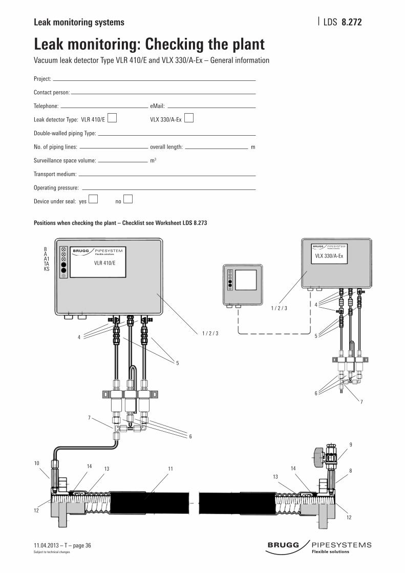
Leak monitoring: Checking the plantVacuum leak detector Type VLR 410/E and VLX 330/A-Ex – General information
1 / 2 / 34
5
6
14
13
9
8
12
14 13
12
10
7
11
A1
B
TAKS
A
VLR 410/E
Positions when checking the plant – Checklist see Worksheet LDS 8.273
VLX 330/A-Ex
1 / 2 / 34
5
6
7
Project:
Contact person:
Telephone: eMail:
Leak detector Type: VLR 410/E VLX 330/A-Ex
Double-walled piping Type:
No. of piping lines: overall length: m
Surveillance space volume: m3
Transport medium:
Operating pressure:
Device under seal: yes no

11.04.2013 – T – page 37
Leak monitoring systems LDS
Subject to technical changes.
8.273
Leak monitoring: Checking the plantVacuum leak detector Type VLR 410/E and VLX 330/A-Ex – Checking the plant
Pos No. of component to be checked functions well defective
1 Vacuum pump
2 Vacuum switch Switching levels: VLR 410/E / VLX 330/A-Ex pump „off“ < 540 mbar / < 540 mbar pump „on“ the level must be at least 15 mbar higher than the switching level measured for „Alarm „on“ Alarm „on“ > 410 mbar / > 330 mbar
3 Filter with non-return valve
tight untight
4 Screw connections: ventilation screw and three-way stopcock
5 Screw connections underneath the leak detector
6 Screwconnections:fluidbarriers
7 T-piece in the connection pipes – single-line system – *
8/9 All screw connections: long nipple/test valve
10 All screw connections: measuring branch
11 Pressure test of individual lines: surveillance space
When piping is untight
12 Screw socket, inner weld seams / GRAPA
13 Screw socket, outer weld seams / GRAPA
14 Screwsocket,allfittingdrillholes
Put into operation yes no
surveillance space – clear passag existingdefectsrectified
Plant put into operation
Vacuum leak detector under seal
Stamp/Date: Signature:
* also in multiple-line system with distributor block

11.04.2013 – T – page 38
Leak monitoring systems LDS
Subject to technical changes.
8.274
Leak monitoring: Checking the plantVacuum leak detector Type VLR 410/E and VLX 330/A-Ex – Test report
Operator: Project:
Test date: Tester: Telephone:
1. First commissioned 2.annual check 3. after fault repair 4. other
FLEXWELL® Safety Pipe Type: STAMANT Type: SECON®-X Type: Transport medium:
Pipe length m: No. lines: Laying: horizontal vertical
Type leak detector: No. of device: built (year):
1. Test of vacuum switch pump off: mbar
pump on: mbar Alarm on: mbar(Correct levels: pump off: < 540 mbar / pump on: > 425 mbar / Alarm on: > 410 mbar) pump on: at least 15 mbar higher than level measured for Alarm on
2. Pumping head of vacuum pump: mbar
Pumpingheadsufficient: yes no repaired
3. Tightness of leak detector determined*: yes no repaired
4. Connection pipes – kinks and crimping: yes no repaired
5. Clear passage through suction pipe: yes no repaired
6. Clear passage through measuring lead: yes no repaired
7. Clear passage through measuring lead: yes no repaired
8. Tightness of leak detector determined* : yes no repaired
Laying with ZD – function OK (Alarm triggered latest at 410 mbar): yes no repaired
Control cable ZD connected to leak detector: yes no repaired
Vertical laying with solenoid valve – function OK: yes no repaired
Permanent power supply connection, non-detachable: yes no repaired
Alarm of leak detector OK: yes no repaired
Leak detector system functional and operationally safe: yes no
Leak detector system as per approval: yes no
Remarks:
Date: Signature of expert: Company stamp:
* see Page 18, leak detector documentation VLR (must be with device)

11.04.2013 – T – page 39
Leak monitoring systems LDS
Subject to technical changes.
Project:
Contact person:
Telephone: eMail:
Double-walled piping Type:
No. of lines: Overall length: m
Surveillance space volume: m3
Substance transported:
Operating pressure:
Device under seal: yes no
DLR-G ...
8.362
Leak monitoring: Checking the plantPositive pressure leak detector Type DLR-G ... and DLR-P 2.0 – General information
1 / 2 / 3
6
5 / 7
13
9
8
12
14 13
12
10 11 14
Positions when checking the plant – Checklist see Worksheet LDS 8.363
Leak detector
DLR-P 2.0
DLR-G stationär mobil
Details of procedure for checking the plant Leak monitoring see Worksheets LDS 8.270 and LDS 8.271
5 / 7 / 15 / 16
17
6
11 9
8
12
1310
DLR-P2.0
11.04.2013 – T – page 40
Leak monitoring systems LDS
Subject to technical changes.
8.363
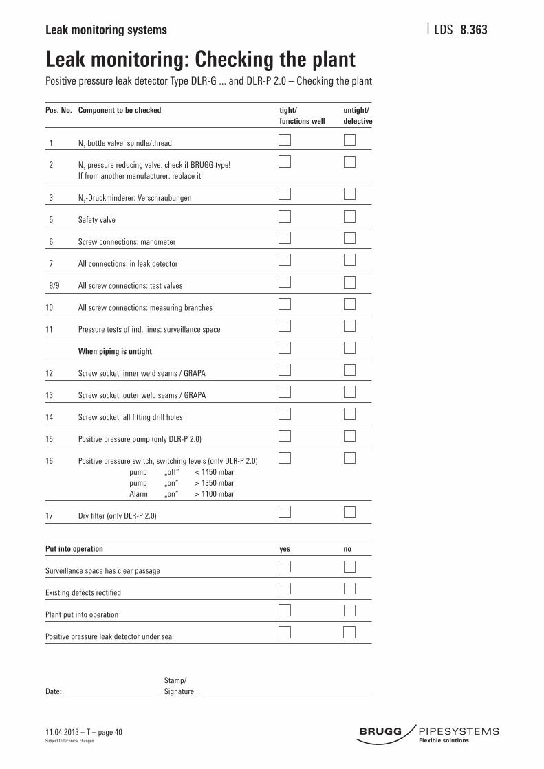
Leak monitoring: Checking the plantPositive pressure leak detector Type DLR-G ... and DLR-P 2.0 – Checking the plant
Pos. No. Component to be checked tight/ untight/ functions well defective
1 N2 bottle valve: spindle/thread
2 N2 pressure reducing valve: check if BRUGG type! If from another manufacturer: replace it!
3 N2-Druckminderer: Verschraubungen
5 Safety valve
6 Screw connections: manometer
7 All connections: in leak detector
8/9 All screw connections: test valves
10 All screw connections: measuring branches
11 Pressure tests of ind. lines: surveillance space
When piping is untight
12 Screw socket, inner weld seams / GRAPA
13 Screw socket, outer weld seams / GRAPA
14 Screwsocket,allfittingdrillholes
15 Positive pressure pump (only DLR-P 2.0)
16 Positive pressure switch, switching levels (only DLR-P 2.0) pump „off“ < 1450 mbar pump „on“ > 1350 mbar Alarm „on“ > 1100 mbar
17 Dryfilter(onlyDLR-P2.0)
Put into operation yes no
Surveillance space has clear passage Existingdefectsrectified
Plant put into operation
Positive pressure leak detector under seal
Stamp/Date: Signature:

11.04.2013 – T – page 41
Leak monitoring systems LDS
Subject to technical changes.
8.364
Leak monitoring: Checking the plantPositive pressure leak detector Type DLR-G ... and DLR-P 2.0 – Test report
Operator: Project:
Test date: Tester: Telephone:
1. First commissioned 2. Annual check 3. After fault repair 4. other
FLEXWELL® Safety Pipe Type: STAMANT Type: SECON®-X Type: Transport medium:
Pipe length m: No. of lines: Laying: underground surface
Type leak detector:: DLR-G Operating mode: stationary mobile DLR-P 2.0 Device no.: Built (year):
Tightness of leak detector determined: pressure drop bar in 120 min. yes no repaired
Connection pipe – kinks and crimping: yes no repaired
Clear passage through connection pipe: yes no repaired
Tightness of leak detector determined: pressure drop bar in 120 min. yes no repaired
Potential-free outlet (clamp 11/12) – Function OK: yes no repaired
Permanent power supply connection, non-detachable: yes no repaired
Alarm of leak detector OK: yes no repaired
Leak detector system functional and operationally safe: yes no
Leak detector system as per approval: yes no
Remarks:
Date: Signature of expert: Company stamp:
Switching levels measured:
PAE (Alarm on): bar PPA (top-up off): bar PDM (supply pressure at pressure reducing valve): bar
Correct PAE PPA PDM
levels bar bar bar
DLR-G 1 > 1 < 2 2,5
DLR-G 2 > 2 < 3 3,5
DLR-G 3 > 3 < 4 4,5
DLR-G 4 > 4 < 5 5,5
DLR-G 5 > 5 < 6 6,5
DLR-G 6 > 6 < 7 7,5
DLR-G 7 > 7 < 8 8,5
DLR-G 10 > 10 < 12 13
DLR-G 11 > 11 < 13 14
Correct PAE PPA PDM
levels bar bar bar
DLR-G 12 > 13 < 14 15
DLR-G 13 > 13 < 15 16
DLR-G 14 > 14 < 16 7
DLR-G 15 > 15 < 17 18
DLR-G 16 > 16 < 18 19
DLR-G 17 > 17 < 19 20
DLR-G 18 > 18 < 20 21
DLR-G 21 > 21 < 23 24
DLR-G 23 > 23 < 25 25

11.04.2013 – T – page 42
Leak monitoring systems LDS
Subject to technical changes.
8.380
Locating the leak inner and outer pipeProcedure
Leak monitoring
Flammableorwater-hazardousfluidsaretransportedthroughtheinnermediumpipeofadouble-walledpipesystem.Theoutercontainmentpipeprevents uncontrolled spillage of the dangerous transport medium if leaks occur. Approved leak detectors can be connected to the surveillance space between the inner and outer pipes for permanent leak monitoring on the vacuum or positive pressure principle. The leak detectors regulate the monitoring pressure in the surveillance space of the double-walled safety pipe and register any pressure changes when either the inner or outer pipe is damaged. When damage occurs, the leak detector gives an acoustic or optical alarm signal which can be transmitted over long distances via potential-free relay contacts.
Locating the leak
Ifthealarmisgiven,firstofallacheckshouldbecarriedoutonalleasilyaccessibleandvisiblepartsofthepipingsuchastheleakdetector,connectionpipesandtestvalvesattheendconnections.Thenextstepistoexaminetheweldorsolderseamsofthevisibleconnectionfittings(inner /outer pipe).
If the leak has still not been found, the piping itself needs to be checked. It is recommended for this to detach all connections to further piping aboveground,toinstallblankflangesatbothendsandtomountamanometerfortheinnerpipeatoneend.Afterthat,thesurveillancespaceshould be pressurized and checked to see whether the pressure leaks out into the inner pipe or into the environment.
The leak detector and the connection pipes
Untightness in the leak detector or in the connection pipes can as a rule be easily detected by means of a pressure test and spraying on bubble-formingfluid.
Leaks in the outer pipe
If the outer pipe is damaged it is recommended to check whether earth-moving work has been carried out along the piping route. The great majority of outer pipe damage is caused by mechanical impact from outside (e.g. by mechanical excavators). For this reason it makes sense to checkfordamagetotheouterpipesfirstinsuchareas.
Iftheleakcannotbefoundinthisway,thesurveillancespacebetweeninnerandouterpipecanbecanbefilledwithareadilyvolatilegas,e.g.helium, to locate the leak. The gas escapes through the leak and rises to the surface, where it can be detected by using a gas detector. If the pipe route runs underneath a concrete or asphalt surface, holes can be drilled for this at intervals of 1 m to 2 m.
Leaks in the inner pipe
Oneoftheoptionsforlocatingaleakintheinnerpipeisviatheultrasonicmethod.Inthis,thesurveillancespaceisfilledwithnitrogen.Thenitrogenenterstheinnerpipethroughtheleak,causingaflownoise.Anultrasoundsensorwhichispulledslowlythroughtheinnerpipe registers this noise and reports it to a display unit. By reading off the metre indication on the pulling wire of the sensor, it can then be determined how far along the pipe from the end the leak is located.

11.04.2013 – T – page 43
Leak monitoring systems LDS
Subject to technical changes.
Notes

Pipe systems for the futureDistrict heating – Industry – Petrol stations – System packages
Your partner for pipe systemsWe are the people you should talk to when youneedtofindefficientsolutionsfortransporting liquid materials. With our project engineers, development department, in-house production unit, and our professio-nalteamoffitters,wehavetheknow-howand the resources to look after your projects competently and reliably in the sectors of heating systems, petrol station construction, industrial plant construction, and system packages.
International networkOur global partnership network can be reached on site at any time. More than 34 partners in 20 different countries will look after you wherever you are.
Brugg Rohrsystem AG
Industriestrasse 39
CH-5314 Kleindöttingen
phone +41 (0)56 268 78 78
fax +41 (0)56 268 78 79
www.pipesystems.com
BRUGG Rohrsysteme GmbH
Adolf-Oesterheld-Straße 31
D-31515 Wunstorf
phone +49 (0)50 31 170-0
fax +49 (0)50 31 170-170
www.brugg.de
A company of the BRUGG Group
Customer-specifi c solutionsBruggisthefullserviceproviderinthefieldof single-wall, double-wall and insulated pipe systems. This know-how allows us to manufactureproject-specificcustomiseditems.
Give us a call! Our engineers would be pleased to advise you andfindamade-to-measuresolution.
!! 5 mm verkürzt !!
04 /
13 /
250
ex.
/ 84
6800
31 /
pict
ures
by
Key


![Underground Piping and Tanks Inspection and Monitoring …Underground Piping and Tanks Inspection and Monitoring Program 2.0 Cont. [18] NACE Standard Practice RP0169-2007, “Control](https://img.pdfslide.us/doc/110x75/60faa76cf39b886e8a7d9ff4/underground-piping-and-tanks-inspection-and-monitoring-underground-piping-and-tanks.jpg)