Embed Size (px)
Citation preview
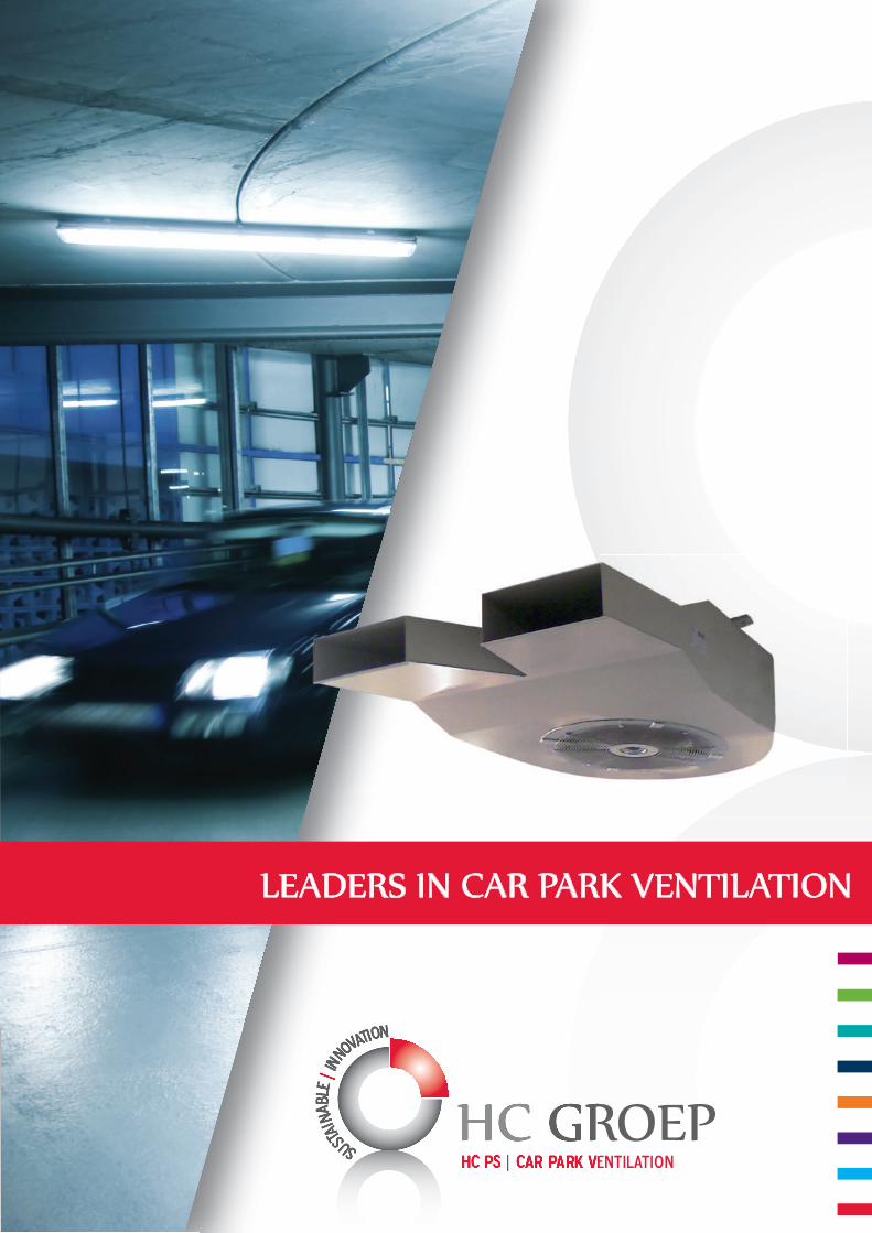
LEADERS IN CAR PARK VENTILATION
22
CONTENTSContents 2
HC PS, you do the maths 3
An introduction 4
Our products 5
Special services 7
Rules and regulations - smoke and heat 8
Car park ventilation possibilities - pollutants 10
Technical support 11
Innovative, tailored solutions - R & D 12
Proving the system 14
Computational fluid dynamics (CFD) 16
Selected reference projects 18
Distributors 23
3
HC PS,YOU DO THE MATHS:
+
+
+
+
+
Experts in global regulations
Thanks to our lengthy international experience and careful selection of distributors,
we have gained extensive knowledge of regulations worldwide.
Slim designs
We not only have a slim induction fan, but we are constantly striving to decrease
the whole installation size. Our smart designs enable us to limit the number of
fans and the motor power required to run them. This allows us to deliver energy
efficient systems with lower running costs. Help make the world a bit more green
by reducing energy consumption!
Smart designs
Every car park is unique and requires its own ventilation design. The first step in the
construction of an efficient ventilation system is the intelligent positioning of openings
and ventilation shafts. Our distributors are trained to assist consultants and architects
in making optimal use of the building characteristics to create smart designs. They can
always rely on support from our main office.
Increased system performance
By integrating the regulatory demands into our smart designs, we are able to
optimise system performance. This results in lower investment, maintenance and
operating costs. A detailed study of the individual car park characteristics can
reduce the number of thrust fans by up to 65%.
Innovation
The HC PS research and development department is constantly looking for new
ways to optimise system performance. We were the first to introduce the new
generation of thrust fans called induction fans and we will continue the process of
improving system performance.
____
= HC PS CAR PARK VENTILATION
4
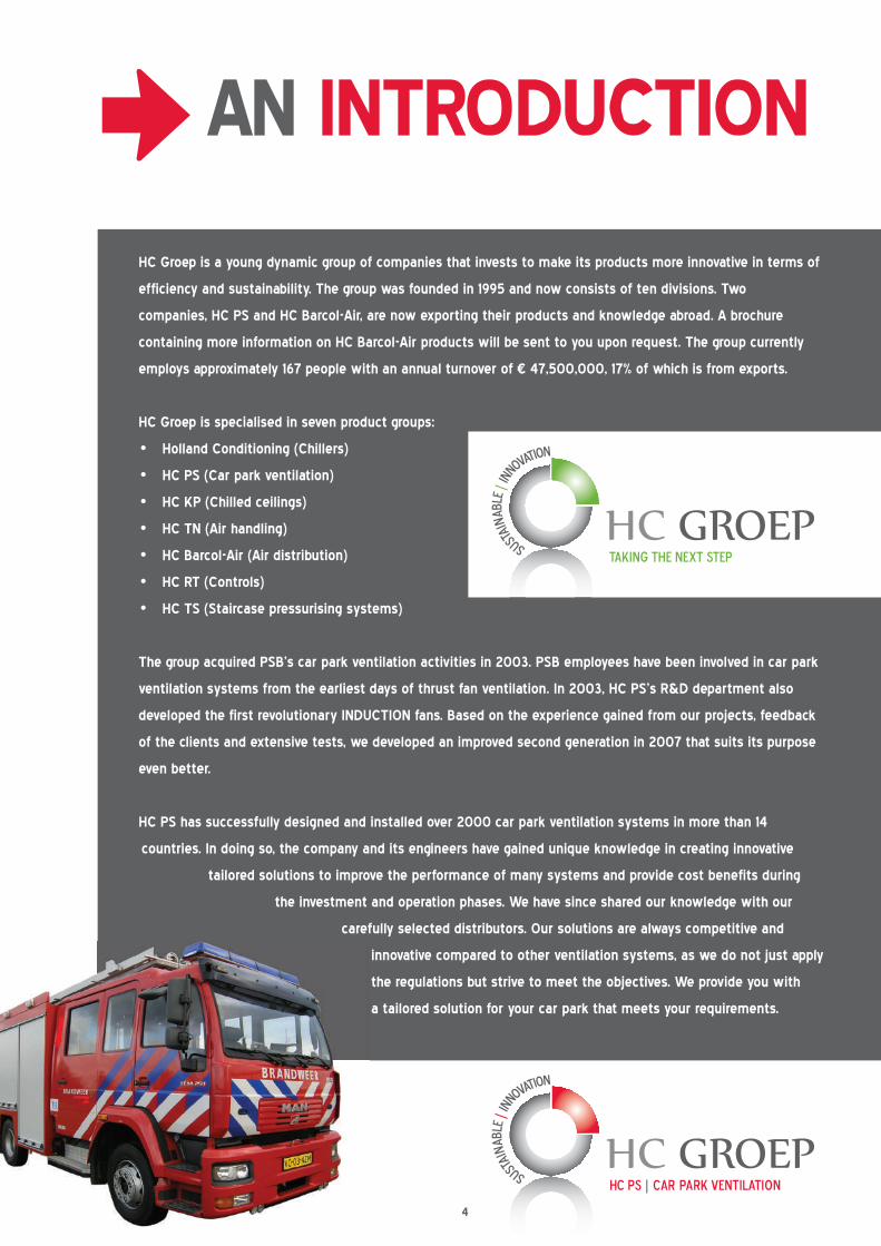
AN INTRODUCTION
HC Groep is a young dynamic group of companies that invests to make its products more innovative in terms of
efficiency and sustainability. The group was founded in 1995 and now consists of ten divisions. Two
companies, HC PS and HC Barcol-Air, are now exporting their products and knowledge abroad. A brochure
containing more information on HC Barcol-Air products will be sent to you upon request. The group currently
employs approximately 167 people with an annual turnover of € 47,500,000, 17% of which is from exports.
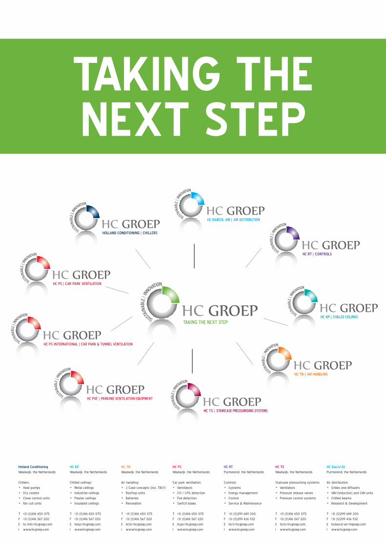
HC Groep is specialised in seven product groups:
• Holland Conditioning (Chillers)
• HC PS (Car park ventilation)
• HC KP (Chilled ceilings)
• HC TN (Air handling)
• HC Barcol-Air (Air distribution)
• HC RT (Controls)
• HC TS (Staircase pressurising systems)
The group acquired PSB’s car park ventilation activities in 2003. PSB employees have been involved in car park
ventilation systems from the earliest days of thrust fan ventilation. In 2003, HC PS’s R&D department also
developed the first revolutionary INDUCTION fans. Based on the experience gained from our projects, feedback
of the clients and extensive tests, we developed an improved second generation in 2007 that suits its purpose
even better.
HC PS has successfully designed and installed over 2000 car park ventilation systems in more than 14
countries. In doing so, the company and its engineers have gained unique knowledge in creating innovative
tailored solutions to improve the performance of many systems and provide cost benefits during
the investment and operation phases. We have since shared our knowledge with our
carefully selected distributors. Our solutions are always competitive and
innovative compared to other ventilation systems, as we do not just apply
the regulations but strive to meet the objectives. We provide you with
a tailored solution for your car park that meets your requirements.
>

5
OUR PRODUCTS> INDUCTION FANS v2
In 2003 HC PS developed, patented (patent 1018285) and introduced the modern induction fan. The second
generation was implemented in 2007. This new and unique generation of fans has been developed to provide
many technical and financial benefits and advantages, using the unique patented outlet venturi and the ultra-flat
centrifugal impeller, resulting in a very low installation height of 257 mm or 325 mm. The HC PS induction fan can
induce up to 19 times the air actually passing through the fan.
The minimised casing height in combination with the special designed outlet nozzles enables the designer to
position the fans at the ideal location, since they do not interfere with traffic circulation.
This flexibility allows for the following:
• A reduction in the number of thrust fans required (by up to 65%) due to improved system performance;
• Lower energy consumption;
• Fewer cables, including ancillaries;
• Lower installation costs;
• Lower maintenance costs.
Type IDV-HC-50v2
• Nominal maximum thrust 50 N;
• Nominal maximum air volume 1.9 m3/h;
• Nominal maximum outlet velocity 22 m/s;
• Nominal maximum power 1,3 kW 3 A;
• Specially designed and patented nozzle for car park applications;
• Up to 95% system efficiency;
• Projection up to 1 per 800 m2 per fan;
• 300˚C - 60 min. (class F300) in accordance with EN 12101-3.
Type IDV-HC-100v2
• Nominal maximum thrust 100 N;
• Nominal maximum air volume 3.1 m3/h;
• Nominal maximum outlet velocity 28 m/s;
• Nominal maximum power 2.2 kW, 6 A;
• Specially designed and patented nozzle for car park applications;
• Up to 95% system efficiency;
• Projection up to 1 each 1,600 m2 per fan;
• 300˚C - 60 min. (class F300) in accordance with EN 12101-3.
Did you know...
...that HC PS also
provides tunnel
ventilation?
Ask our sales
representative for
more information!
• Nominal maximum outlet velocity 22 m/s;
66
OUR PRODUCTS
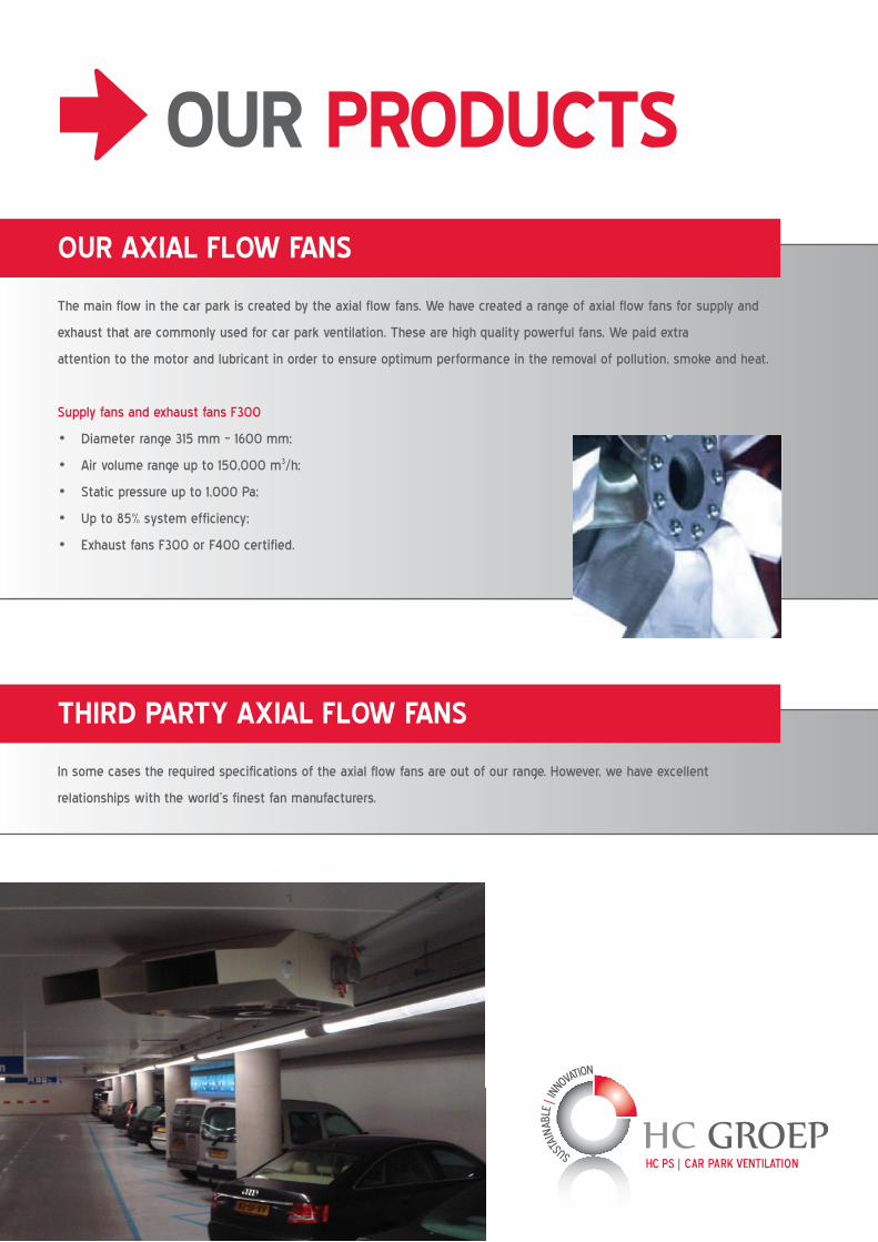
OUR AXIAL FLOW FANS
The main flow in the car park is created by the axial flow fans. We have created a range of axial flow fans for supply and
exhaust that are commonly used for car park ventilation. These are high quality powerful fans. We paid extra
attention to the motor and lubricant in order to ensure optimum performance in the removal of pollution, smoke and heat.
Supply fans and exhaust fans F300
• Diameter range 315 mm – 1600 mm;
• Air volume range up to 150,000 m3/h;
• Static pressure up to 1,000 Pa;
• Up to 85% system efficiency;
• Exhaust fans F300 or F400 certified.
THIRD PARTY AXIAL FLOW FANS
In some cases the required specifications of the axial flow fans are out of our range. However, we have excellent
relationships with the world’s finest fan manufacturers.
>

7
Conceptual design
The design of a car park ventilation system has an effect on the entire building design. Think of the shafts
for extraction of pollutants and smoke. Not only do these demand space in the building, but they are also
subject to special requirements in order to comply with local codes. A conceptual design will provide you
with the needed spaces and locations in order to have a suitable and efficient ventilation system at the
end. We strongly advise involving us in the architectural design phase.
Detailed engineering
Once the building has been designed and the general locations for shafts and openings are determined,
then we can begin the detailed engineering of the system. In this phase, we will calculate the exact volume
flows and thrust necessary in order to comply with the local codes and regulations. This is best done in
combination with the other disciplines, since the car park is usually located below the building and therefore
influences the entire structure. The detailed engineering phase concludes with a report on the requirements
of the system and its components.
Tender document description
Based on the detailed engineering information, we can provide you with content for the tender documents in
order to ensure that the suppliers can meet the system performance and component quality objectives. With this
service we also provide you with background information in order to determine whether the components comply with the requirements.
Installation drawings
In addition to the tender documents, we can also provide the installation drawings in varying degrees of detail: from drawings that
show only a general outline of the ventilation system to a level in which all components, construction and specifications are included,
all in accordance with the tender document specifications.
System design approval
Car parks often require exemptions to building regulations and local authorities must be convinced that the plans meet safety
objectives. We possess the knowledge of the regulations, the ventilation system and the calculation methods (including CFD)
necessary to prove the system performance and the level of safety. Our report includes all of the information the local authorities
need to check if the system complies with the regulation objectives.
Product selection assist
We can assist you by selecting products based on the requirements described in the tender documents, local regulations, building
limits and your own preferences. When we select a product you can be sure that it meets your performance requirements and
preferences.
Commissioning and testing
In the final phase, the ventilation system is commissioned and tested to ensure that the system meets the requirements as intended
in the design phase and as promised by the supplier. In many cases, the local authorities also require that the system is tested by an
independent company. We have the material and test protocols for cold smoke tests and hot smoke tests (0.6 – 4 MW fire). We can
guarantee that the system has been installed and performs according to specifications.
SPECIAL SERVICES>

8
Around the world, car parks are subject to a wide variety of regulations and requirements for ventilation and these
specifications are constantly changing. This mosaic of codes and standards is due to the fact that car park ventilation is
not subject to building regulations. The finish of the spaces, the floor area of the fire compartment, production of toxic
gases and fire size and source are very different from other types of buildings. The result is a great deal of diversity in
safety standards for car parks. HC PS has been active on the international market for a long time and has experience
with all sorts of regulations. We specialise in designing systems that meet local regulatory demands or even improve the
performance to a higher level of safety. Within HC PS we recognise three levels of smoke and heat exhaust performance:
SMOKE CLEARANCE
This type of system is based on a minimum air exchange rate per hour. This system will mainly exhaust the smoke and
heat after the fire has been extinguished rather than improve the environment during the fire itself. Some regulations
specify the maximum time permitted to achieve a certain length of visibility after suppression.
This type of system is comparable with the British Standard 7346-7:2006 clause 9, which states that the system is not
intended to maintain any area of a car park clear of smoke, to limit smoke density or temperature to within any specific
limits or to assist means of escape.
Wherein the minimum demanded exhaust volume rate is 10 air changes per hour and thrust fans are to assist the
distribution of supply air over the car park and to avoid non-ventilated volumes.
HC PS always recommends considering the exhaust mixture temperature for the maximum design fire heat release rate
against the demanded fire class. If this value is exceeded, the ventilation system can fail during a real car fire and result
in a catastrophe.
SMOKE EXTRACTION
This intermediate type of ventilation will limit the smoke
spread within the car park volume on the level where the fire
occurs. This will enable those present to evacuate the car park
level that is affected and will provide safe access for the fire
brigade upon arrival. The main objective of this system is to
limit the spread of smoke within a predefined area. This type
of system requires a minimum ventilation rate, but depending
on the size of the car park the rate could be achieved with
10 air changes per hour. This type of system also requires an
expert design, since control of the system components to
balance the air flows is vital.
>
>
RULES AND REGULATIONS – SMOKE AND HEAT
9
Although regulations do not specify this type of system, in many countries the authorities do request that whenever the
maximum fire compartment size is exceeded, a ventilation system should provide an improvement. For instance this is
required by the Irish fire consultants and by the Portuguese authorities.
At HC PS we believe that this type of system provides a much higher level of safety for persons present and for the fire
brigade, and it can generally be realised with a minimum of extra investments. Furthermore, with this type of system the
exhaust mixture temperature should also be checked.
SMOKE AND HEAT CONTROL
This type of ventilation is primarily intended to enable the fire brigade to efficiently and adequately locate and suppress
the fire. This system has been installed in many car parks around the world and has proven itself during real fires. It has
been designed to maximise the airflow over the seat of the fire to force the smoke in one direction. In general, regulations
require that the smoke spread upstream is limited to a certain range. This type of system requires an expert design,
since it requires a high level of control of the system components in order to balance the air flows.
This type of system is comparable with the British Standard 7346-7:2006 clause 10 and Dutch and Belgian regulations.
It is also embedded in proposed European regulations.
According to the British Standard, the design should be such that the bulk air velocity induced by the thrust
fans is sufficient to halt the advance of the ceiling jet within 10 m from the fire location for all possible fire
locations in the direction opposite to the induced bulk air flow. The Belgian regulations require a minimum
velocity over the fire depending on the width of the fire zone or an equal performing system proved by CFD
(Computational Fluid Dynamics). The smoke spread upstream should be limited
within 15 meters from the seat of the fire from a point in the car park that is free
of smoke. The Dutch regulations demand that the seat of the fire is visible from
the fire brigade’s point of access. This can for instance be proven by a light emis-
sion calculation, with minimum visibility standards.
Although the system performs somewhat differently, the main objective is the
same. This means that the design method and compliance procedures are also
the same. HC PS has invested in testing procedures, CFD’s, scaled models etc.
in order to increase understanding in the process.
>
{
RULES AND REGULATIONS – SMOKE AND HEAT
Experts are needed to reach your goals
and regulatory objectives!
10
CAR PARK VENTILATION POSSIBILITIES – POLLUTANTS
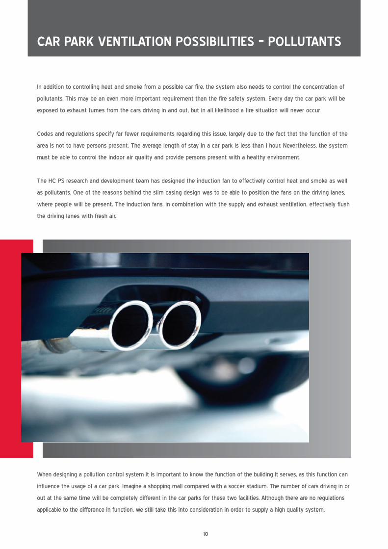
In addition to controlling heat and smoke from a possible car fire, the system also needs to control the concentration of
pollutants. This may be an even more important requirement than the fire safety system. Every day the car park will be
exposed to exhaust fumes from the cars driving in and out, but in all likelihood a fire situation will never occur.
Codes and regulations specify far fewer requirements regarding this issue, largely due to the fact that the function of the
area is not to have persons present. The average length of stay in a car park is less than 1 hour. Nevertheless, the system
must be able to control the indoor air quality and provide persons present with a healthy environment.
The HC PS research and development team has designed the induction fan to effectively control heat and smoke as well
as pollutants. One of the reasons behind the slim casing design was to be able to position the fans on the driving lanes,
where people will be present. The induction fans, in combination with the supply and exhaust ventilation, effectively flush
the driving lanes with fresh air.
When designing a pollution control system it is important to know the function of the building it serves, as this function can
influence the usage of a car park. Imagine a shopping mall compared with a soccer stadium. The number of cars driving in or
out at the same time will be completely different in the car parks for these two facilities. Although there are no regulations
applicable to the difference in function, we still take this into consideration in order to supply a high quality system.
11
In order to meet the high quality standards demanded by the
industry, we have set up a special training program for our distributors
to provide local support and consultancy on car park designs. And
of course our engineers are available to support the local distributor
whenever required.
The highest possible improvement of sustainability and reduction of
costs can only be reached when we are involved in the design process
from the earliest pre-design phase. Otherwise we can only optimise
the system within the set limits. During the design phase we can
assist you with:
• Positing and dimensioning the shafts with respect to the main
entrances and exits. This influences the total ventilation system
and its performance;
• A sketch design with thrust fan locations;
• Attending meetings with fire department and / or government
authorities for system approval;
• A variety of calculations to prove the system performance;
• Arrange CFD simulations (performed by a third party) to analyse
the system performance, and when needed optimise the system.
Upon request, we can also provide a full engineering package and on-
site support during the formal design phase until delivery to the client.
TECHNICAL SUPPORT
12
INNOVATIVE, TAILORED SOLUTIONS - R&D
As concepts of safety, air quality and sustainability are constantly changing, there is a need to continuously develop
products and system designs. Our research and development department is always exploring new possibilities and testing
new ideas. The knowledge generated by their efforts is then passed on to the engineers and distributors. We take car
park ventilation very seriously,
as it involves providing a fire
safety system and an indoor
environment system to protect
people’s health.
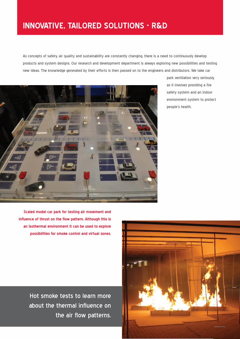
Scaled model car park for testing air movement and
influence of thrust on the flow pattern. Although this is
an isothermal environment it can be used to explore
possibilities for smoke control and virtual zones.
12
Hot smoke tests to learn more
about the thermal influence on
the air flow patterns.
13
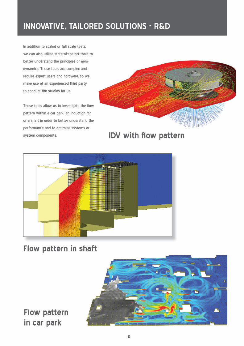
INNOVATIVE, TAILORED SOLUTIONS - R&D
Flow pattern in shaft
Flow pattern in car park
In addition to scaled or full scale tests,
we can also utilise state-of-the-art tools to
better understand the principles of aero-
dynamics. These tools are complex and
require expert users and hardware, so we
make use of an experienced third party
to conduct the studies for us.
These tools allow us to investigate the flow
pattern within a car park, an induction fan
or a shaft in order to better understand the
performance and to optimise systems or
system components. IDV with flow pattern

14
Manual calculations
We have conducted an exhaustive study of the literature on the issue in order to find all of the useful tools and formulas
available so we can realise quick analyses and indicate the performance of a system.
Our services include:
• Determine static pressure head losses by relatively simple manual calculations, based on experimental data which is
recognised worldwide.
• Calculate the maximum possible temperature in the shaft due to the expected heat release rate.
• Calculate the remaining velocity of the supply air, taking into account the expansion caused by the fire.
PROVING THE SYSTEM
With our innovative designs it is vital that the proposed
solution is supported by evidence of the performance. Creating
a performance-based design requires a detailed understanding
of local regulations in order to analyse the safety objectives.
This results in a set of performance criteria. Once these criteria
are determined it is possible to make a proper study to prove
that the proposed system complies with local legislation.
Depending on the criteria, a variety of tools can be used to
prove the performance.
14
15
CFD simulations
In the design phase of a building it is not possible to conduct full-scale tests. However, using Computational Fluid
Dynamics (CFD) it is possible to conduct full scaled tests in controlled environments. The advantage to this is that the
boundary conditions are controllable, which creates the perfect test environment to compare different designs.
We work together with consultants that are experts in CFD and other simulation tools. We have also trained our team
and distributors to verify the quality of CFD’s. On the following pages you can find more information regarding this state-
of-the-art technique. The results of a CFD simulation show the smoke spread over a period of time, making it possible
to analyse the resulting length of visibility in the car park and the temperature at all locations within the volume. It is
also possible to analyse other variables, such as relative pressure, radiation etc. These analyses can provide very useful
information to improve the design.
Cold smoke
In this test a smoke generator is set up at different locations in the car park that are expected to be the most critical.
Next, an amount of smoke is released before starting the ventilation system or the smoke is generated when the
ventilation system is in operation. The first test is to check the ventilation efficiency, blind spots and dilution rate. The
second test is to indicate local air movement. This test excludes all thermodynamic effects and can be assumed to be
isothermal. This is the most basic test. The results can be used for determining the location for the tests described
below.
Hot smoke
This test has been specially developed for testing fire ventilation systems since the thermo-
and fire dynamic effects significantly influence the airflow in the car park. A controlled pool fire
with a set fire surface is used to simulate the seat of the fire. A continuous heat release
is produced by the fire trays. By changing the number of fire trays, we can adjust
the total heat release rate. When using an alcoholic pool fire no toxic gases will
be produced. The concrete immediately above the fire and in the critical
temperature zone will be protected by Promatect and temperature
sensors. Since the alcohol fire does not produce visible smoke
during the test, a smoke generator is also used. By changing
the location of the smoke generator, we can visualise
the air flow direction at different positions and
heights. This test produces results that
accurately represent the actual situation.
15
with a set fire surface is used to simulate the seat of the fire. A continuous heat release with a set fire surface is used to simulate the seat of the fire. A continuous heat release
is produced by the fire trays. By changing the number of fire trays, we can adjust is produced by the fire trays. By changing the number of fire trays, we can adjust
the total heat release rate. When using an alcoholic pool fire no toxic gases will
be produced. The concrete immediately above the fire and in the critical
temperature zone will be protected by Promatect and temperature
sensors. Since the alcohol fire does not produce visible smoke
during the test, a smoke generator is also used. By changing
the location of the smoke generator, we can visualise
the air flow direction at different positions and
heights. This test produces results that
accurately represent the actual situation.

16
What is CFD?
CFD stands for Computational Fluid Dynamics and is the analysis of systems involving fluid flows, heat transfer and
associated phenomena with the aid of computer models. It allows for the prediction and analysis of fluid flows through
a predefined geometry before it is actually built. In a CFD simulation, the geometry is divided into several smaller control
volumes, or cells, known as the calculation grid / mesh. Within this grid, numerical techniques are used to solve the
governing equations, which define the aspects of the fluid flows. A wide range of boundary conditions can be applied to
the model parameters, defining walls, inlets, outlets, or openings.
Why use CFD?
The behaviour of fluid flows is often difficult to predict. There are numerous parameters that can influence a flow, all of
which must be taken into account. This makes it difficult, or even impossible, to calculate complex fluid flows manually
or using a simple spreadsheet. A CFD simulation is a tool for predicting these fluid flows with reasonable accuracy and
within a reasonable time frame.
A car park is a good example of a geometry in which complex fluid flows occur. The main flow through the car park
is influenced by walls, columns, beams, thrust fans and unexpected events such as fires. CFD simulations can provide
insights into flow patterns that are very difficult to accurately predict in advance. It is a powerful tool to convince clients.
Example of a complex car park geometry.
COMPUTATIONAL FLUID DYNAMICS (CFD)
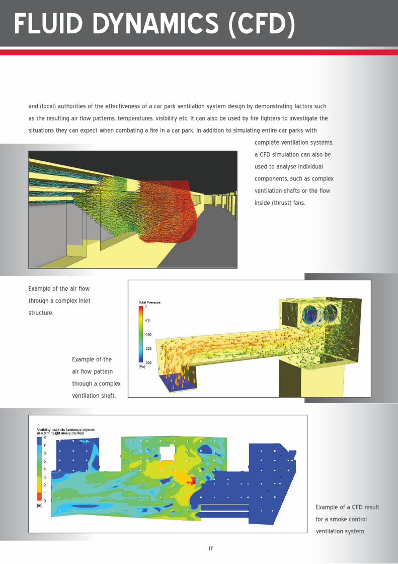
17
Example of a CFD result
for a smoke control
ventilation system.
Example of the air flow
through a complex inlet
structure.
COMPUTATIONAL FLUID DYNAMICS (CFD)
and (local) authorities of the effectiveness of a car park ventilation system design by demonstrating factors such
as the resulting air flow patterns, temperatures, visibility etc. It can also be used by fire fighters to investigate the
situations they can expect when combating a fire in a car park. In addition to simulating entire car parks with
complete ventilation systems,
a CFD simulation can also be
used to analyse individual
components, such as complex
ventilation shafts or the flow
inside (thrust) fans.
Example of the
air flow pattern
through a complex
ventilation shaft.
18
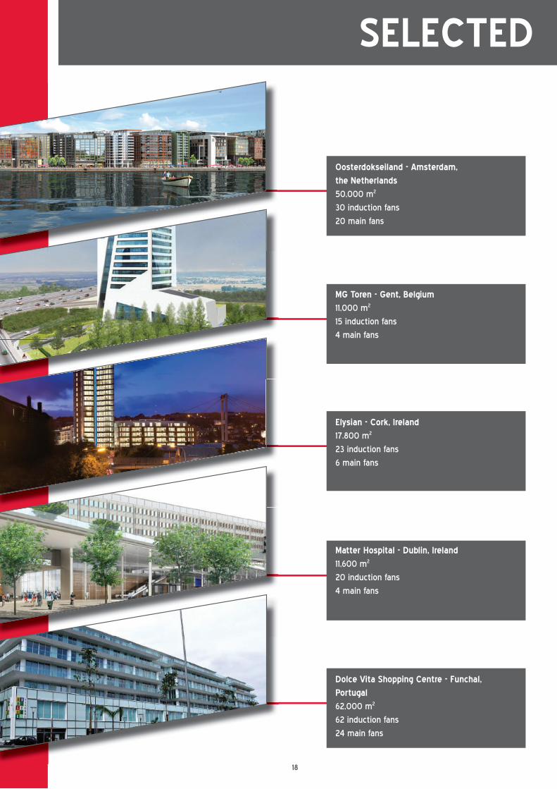
SELECTED REFERENCE PROJECTS
Oosterdokseiland - Amsterdam,
the Netherlands
50,000 m2
30 induction fans
20 main fans
MG Toren - Gent, Belgium
11,000 m2
15 induction fans
4 main fans
Elysian - Cork, Ireland
17.800 m2
23 induction fans
6 main fans
Matter Hospital - Dublin, Ireland
11,600 m2
20 induction fans
4 main fans
Dolce Vita Shopping Centre - Funchal,
Portugal
62,000 m2
62 induction fans
24 main fans
19
SELECTED REFERENCE PROJECTS
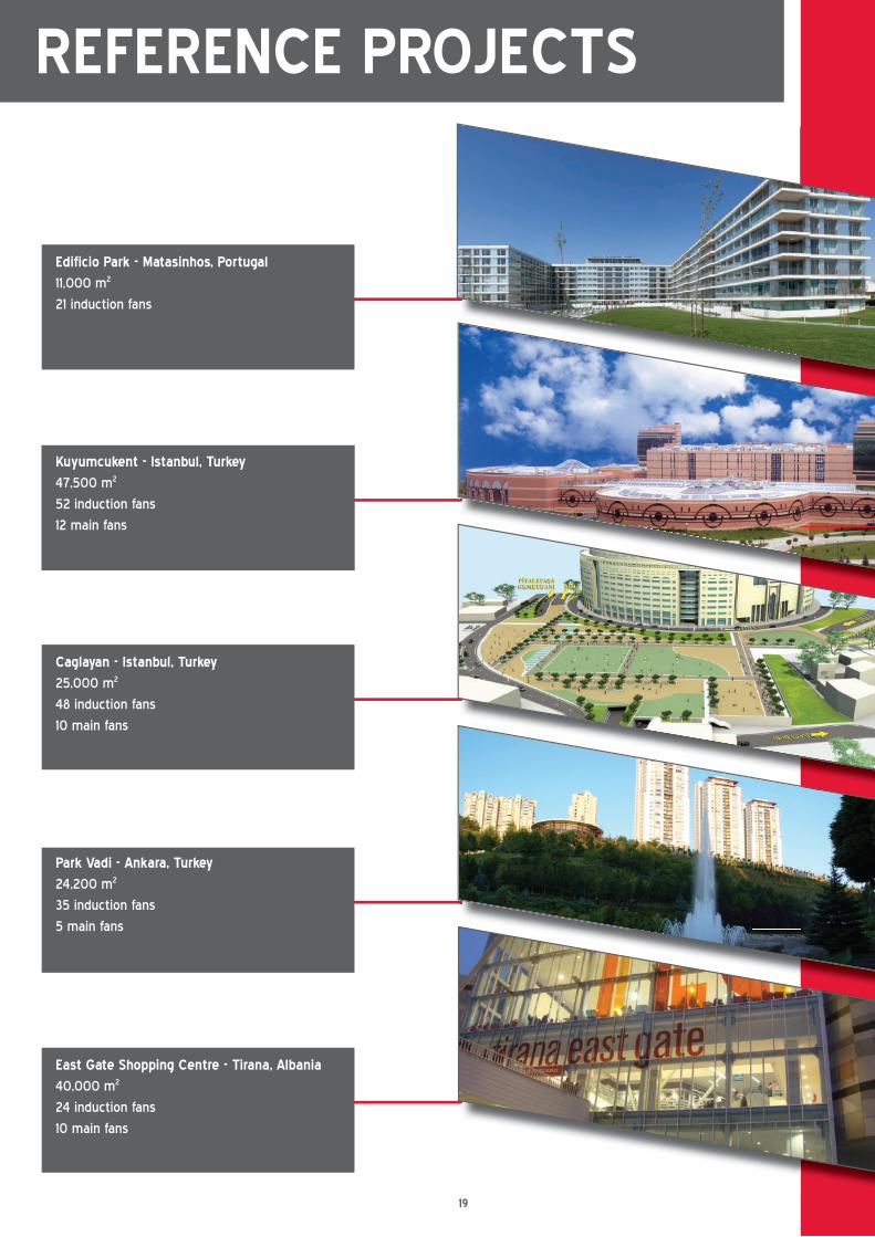
Edificio Park - Matasinhos, Portugal
11,000 m2
21 induction fans
Kuyumcukent - Istanbul, Turkey
47,500 m2
52 induction fans
12 main fans
Caglayan - Istanbul, Turkey
25,000 m2
48 induction fans
10 main fans
Park Vadi - Ankara, Turkey
24,200 m2
35 induction fans
5 main fans
East Gate Shopping Centre - Tirana, Albania
40,000 m2
24 induction fans
10 main fans
20
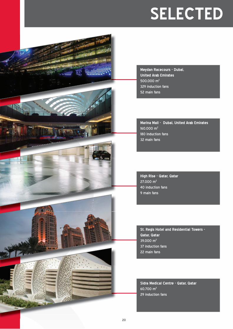
Meydan Racecours - Dubai,
United Arab Emirates
500,000 m2
329 induction fans
52 main fans
Marina Mall - Dubai, United Arab Emirates
160,000 m2
180 induction fans
32 main fans
High Rise - Qatar, Qatar
27,000 m2
40 induction fans
9 main fans
St. Regis Hotel and Residential Towers -
Qatar, Qatar
39,000 m2
37 induction fans
22 main fans
Sidra Medical Centre - Qatar, Qatar
60,700 m2
29 induction fans
SELECTED REFERENCE PROJECTS
21
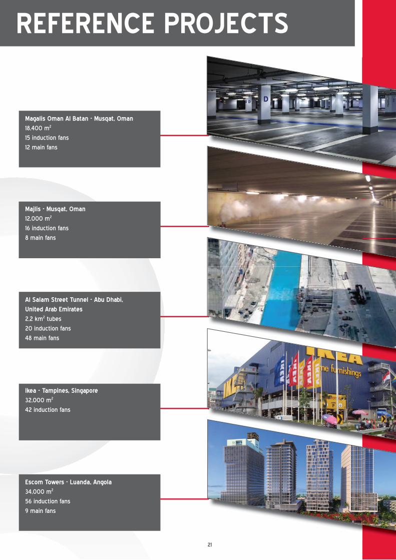
Magalis Oman Al Batan - Musqat, Oman
18,400 m2
15 induction fans
12 main fans
Majlis - Musqat, Oman
12,000 m2
16 induction fans
8 main fans
Al Salam Street Tunnel - Abu Dhabi,
United Arab Emirates
2,2 km2 tubes
20 induction fans
48 main fans
Ikea - Tampines, Singapore
32,000 m2
42 induction fans
Escom Towers - Luanda, Angola
34,000 m2
56 induction fans
9 main fans
SELECTED REFERENCE PROJECTS
22

2323
Please visit our website
www.hcgroep.com for the
most recently updated list
of our worldwide network
of distributors.
DISTRIBUTORS>
AIR DISTRIBUTION
controls
chillers
CHILLED CEILINGS
AIR HANDLING
sTAIRCASE PRESSURISING SYSTEMS
TAKING THE NEXT STEP
Holland Conditioning
Waalwijk, the Netherlands
Chillers:
• Heat pumps
• Dry coolers
• Close control units
• Fan coil units
T +31 (0)416 650 075
F +31 (0)416 567 220
I www.hcgroep.com
HC KP
Waalwijk, the Netherlands
Chilled ceilings:
• Metal ceilings
• Industrial ceilings
• Plaster ceilings
• Insulated ceilings
T +31 (0)416 650 075
F +31 (0)416 567 220
I www.hcgroep.com
HC TN
Waalwijk, the Netherlands
Air handling:
• 3 Case concepts (incl. TB1/1)
• Rooftop units
• Batteries
• Renovation
T +31 (0)416 650 075
F +31 (0)416 567 220
I www.hcgroep.com
HC PS
Waalwijk, the Netherlands
Car park ventilation:
• Ventilators
• CO / LPG detection
• Fire detection
• Switch boxes
T +31 (0)416 650 075
F +31 (0)416 567 220
I www.hcgroep.com
HC RT
Purmerend, the Netherlands
Controls:
• Systems
• Energy management
• Control
• Service & Maintenance
T +31 (0)299 689 300
F +31 (0)299 436 932
I www.hcgroep.com
HC Barcol-Air
Purmerend, the Netherlands
Air distribution:
• Grilles and diffusers
• VAV-(induction) and CAV-units
• Chilled beams
• Research & Development
T +31 (0)299 689 300
F +31 (0)299 436 932
I www.hcgroep.com
HC TS
Waalwijk, the Netherlands
Staircase pressurising systems:
• Ventilators
• Pressure release valves
• Pressure control systems
T +31 (0)416 650 075
F +31 (0)416 567 220
I www.hcgroep.com