Embed Size (px)
Citation preview

PART-LOADLEADER
Certi�ed to Canadian StandardsEFFICIENCY

CWT CHILLER SERIES
PARTIAL LOAD ENERGY SAVING DESIGN
When the CWT chiller is operating at partial load with only some of the compressors running the efficiency increases because the heat exchangers are now oversized. In effect the CWT chillers with multiple compressors in the same circuit can achieve much better efficiency levels compared with competitive chillers with just one compressor per circuit. The diagram illustrates the CWT multiple compressor design energy saving bennefits.
MULTI-COMPRESSOR CONFIGURATION
It is common practice to size chillers for the maximum output required. During normal operating conditions throughout the day and year the maximum output of the chiller is rarely required and for only short periods of time. The CWT chillers use a multiple compressor configuration from model CWT030 and up. This enables the refrigerant system to adapt to the true output required instantaneously. This design results in significant reduction in electrical consumption, a higher efficiency during partial loads because of the over-sized heat exchangers, lower start up current in-rush and an increase in the average life of the compressors. The multi-compressor configuration guarantees higher seasonal energy efficiency verses using a large single compressor unit which would require more energy even in low load periods.
CWT PURESTREAM SERIES WATER CHILLERSThe new CWT Purestream chiller range is specifically designed to meet the stringent cooling requirements of today’s advanced equipment and processes. The CWT range proivides precise temperature control of chilled water temperature while operating over long periods of time with varying load demands for many industries and applications. The range includes several models providing capacities from 2.4 tons to 36.5 tons and designed to be installed indoors or outdoors. The Purestream CWT chillers are equipped with the necessary components to provide reliable effective cooling and energy saving operation. All units are equipped with: • finned aluminium micro-channel condenser • rotary or scroll hermetic compressors • environmentally friendly refrigerant gas R410a• brazed plate evaporator• electric fans with continual speed control • microprocessor controller• ventilated control panel• thermally insulated water storage tank• hydraulic pump• stainless steel condenser filters • water filter and shut-off valves
MULTI-CHANNEL ALUMINUM CONDENSERS
The new Micro-channel aluminium plate condensers guarantee a larger surface area providing enhanced heat exchange when compared to the traditional copper tube condensers. The result is a reduction in the refrigerant charge estimated from 30% to 35% less than the traditional condenser design. The all aluminium condensers are treated which makes them resistant to any galvanic reaction and corrosion. To protect the condensers all CWT chillers include stainless steel mesh condenser filters that are easlily removed for service and cleaning.

R410A REFRIGERANT
Due to its thermal dynamic performance, the R410A refrigerant gas allows the refrigeration system to operate at high efficiency. The higher operating pressure of the R410A refrigerant has allowed for the development of a more compact design chiller range.
EVAPORATOR
The stainless steel brazed plate evaporator is compact in size, extremely efficient and installed independent of the storage tank. The electronic control anti-freeze function keeps the evaporator’s outlet water temperature under control in order to prevent the evaporator from freezing up. A differential pressure switch protects the evaporator against no or low water flow. A mechanical inlet water filter (standard) protects the entire hydraulic circuit against any contamination coming from the system. The models CWT075 to CWT130 are designed with a double refrigerant circuit and single water circuit. This configuration is very efficient with partial loads, compared to independent evaporator solutions.
REFRIGERANT CIRCUIT
The refrigerant circuit is produced by specialized personnal utilizing high quality materials and rigorous brazing procedures that conform to directive 97/23. The refrigerent circuit consists of: AISI 316 stainless steel brazed plate exchanger, micro-channel aluminium condensers, rotary compressors (models CWT007 and CWT010) and scroll compressors designed for R410A refrigerant, dehydration filter, sight glass humidity indicator, thermostatic expansion valve with external equalisation, reverse flow check valves for models with mutli compressors, manual reset high pressure switch and automatic reset low pressure switch, high and low pressure gauges and refrigerant maintanence connection points.
HYDRAULIC CIRCUIT
Composed of a thermally insulated storage tank made of carbon steel or stainless steel c/w: expansion tank, shut-off ball valves, by-pass valve, safety valve, automatic venting valve, differential pressure switch, level sensor, water filter, drain valve, pressure gauge and multi-stage centrifugal electric pump with high efficiency impeller. The high liquid volume to compressor cooling capacity ratio maintains a constant outlet water temperature while minimizing compressor starts and stops. Where the multi-compressor configuration is used the storage tank is smaller which allows for a faster start up to reach plant cooling water requirements. The water storage tank is postioned on the water outlet in order to limit temperature fluctuations due to the compressors being switched on and off. Within the unit there is also a small by-pass tube between the water inlet and outlet designed to prevent problems caused by water valves being closed unintentionally.
ROTARY AND SCROLL COMPRESSOR
CWT chillers utilize rotary and scroll compressors as a standard. These compressors are the best available technology today for the cooling requirments of the CWT chillers. They are known for their reliability and efficiency through their widespread use in the air conditioning and refrigeration industies. The scroll compressor has the additional benefits of quiet operation, no vibration and the ability to adsorb liquid returns. Compressors are mounted on rubber anti-vibration pads designed to reduce noise and the effects of vibration. They are also protected by an electronic device that monitors the phase sequence in order to avoid reverse rotation. Compressors are all equipped with a crankcase heater as standard.

fraMe and CaBinet
All frame and cabinetry material are made from galvanized steel and painted in a powder coat paint finish. This allows for indoor and outdoor installation and provides protection in harsh environments. All fasteners are either stainless steel or electro- galvanized materials. The CWT cabinet was designed so that all parts, particularly those requiring maintenance and cleaning are easy to access without interfering with the chiller operation. The chiller cabinet is accessible on three sides allowing for easy maintenance and also designed with safety to the operator in mind.
fans
The 4/6/8 pole axial fan motors are complete with an external rotor blade which is activated by condensing pressure measured by a pressure transducer. This leads to more regular operation and lower usage which extends the lifespan of the fan motor. All fans have a protection grill, thermally heat protected with automatic reset and class F insulation.
Control Panel The control panel complys with the Canadian electrical code and includes door lock disconnect which prevents access to the control panel when it is powered. The watertight door provides easy access to the electronic controller as well as the numbered panel wires provide easy trouble shooting and maintenance. Each control panel includes: thermo-magnetic motor protectors for the compressors and pump, contactors, autotransformers, compressor rotation direction control devices, ON/OFF switch on the panel door. The control panel also includes an active ventilation system to prevent over heating when the unit is in operation.
hydrauliC CirCuit CirCulation PuMPs
All units are equipped with a high efficiency multi-stage centrifugal pump with steel impeller. All parts coming in contact with fluid are AISI 304 stainless steel. The mechanical seals are carbon/ceramic/EPDM as standard therefore making it possible to use water and ethylene glycol mixtures of up to 30%. The pump motor is 2-pole, self-ventilated, with class F insulation and IP55 protection level. The entire CWT series chillers utilize P3 pump pressure as standard and optional P5 pressure. Double pump option is also avaiable upon request.

CWT CHILLER SERIES
MICROPROCESSOR CONTROLLER
The electronic control micro-processor controls and optimizes all CWT chiller components and functions. The controller regulates theevaporator water outlet temperature, switches pump on and o�, regulates fan speed, controles the compresssors on and o� cyclesbased on water temperature required, while gauranteeing equal operating times to protect the compressors for multi-compressormachines, measurment and display of evaporator inlet and outlet temperature, measurment and display of condensation pressure,control of multiple pump chillers designed to ensure equal pump operating times. The controller also provides the followingalarm messages:• High refrigerant pressure gauge• low refrigerant pressure gauge• water di�erential pressure gauge• compressor thermal/phase sequence control• pump thermal protection• temperature probe failure• pressure probe failure• high water temperature• anti-freeze
User interface is easy and intuitive and the controller can be enabled for “remote” function with it’s clear and visable alarm indicator.The easy-to-follow set up menu allows for easy access to set main operating parameters. The intigrated double display with it’s brightdigital characters provides a complete real time display of the chiller operation and alarm conditions.
FACTORY TESTING
All CWT chillers are factory tested in Canada prior to shipping.
PRESSURE OPERATED BYPASS VALVES
The Primary function is to protect the chiller should any number of situations impede �ow.
Located between the supply and return on the outlet of the chiller it is designed to open should the pressure in the closed loop go beyond the preset level.The POBV will respond to the increased pressure by opening and begin bypassing water or Glycol to the Return Line. The chiller will sense the reduction in load and adjust the number of compressors running or shut o� completely.
The Secondary Function will also allow a single PURESTREAM CHILLER with Adaptable load Operation to supply Chilled Water orGlycol to multiple loads.
An example would be in the brewing industry or any cooling loop that has previously been setup to run with City Water.Water is diverted around the brewing process depending on what step the process is in. Often these systems have a switchthat opens and closes feed water into the cooling jacket in the fermentation tank or in the Wort Chiller. In a chiller withouta bypass valve, this would not be possible as closing the valve would DEADHEAD the pump. The POBV will open to allow the system to continue to run at a lower loop �ow and also scale back the refrigeration e�ect to match the load.

APPLICATIONS
• Breweries, distilling
• Plastics (injection, blow moulding, extrusion, film extrusion, thermoforming)
• Printing and Graphics (manufacture, printing, cardboard, labels, plastic film)
• Medical imaging
• Food (beverage, confectionary, chocolate, processing, storage)
• Mechanical (welding, cutting, profiling, polishing, rolling, grinding)
• Other (wood, ceramics, gold, biogas pharmaceutical, compressed air, textile)
• Hydraulic circuit cooling, Machine Tool
• Paint and Finishing
• EDM
SAFETY AND CONTROL DEVICES
• Low Ambient Wind Panels for Canadian winters.
• Non-Ferrous design (Now standard for Canada).
• Temperature probes control and display evaporator inlet and outlet water temperatures to prevent freeze-ups.
• A high pressure gauge/switch signals the chiller to stop operation if it experiences irregular refrigerant pressure on the circuit’s high pressure side. Once the problem is corrected it can be manually reset.
• A low pressure gauge stops the chiller if the refrigerant pressures are too low and the reset is automatic once the pressure has returned to the preset value.
• A pressure transducer registers high refrigeration system pressure allowing fan speed regulation with a phase - cutting electronic. regulator that allows the chiller to work with an outdoor air temperature of up to 14˚F.
• A level sensor is installed on water storage tank which stops the chiller if water capacity is too low.
• A water differential pressure gauge/switch stops the chiller if water capacity is too low.
• In order to prevent compressors from rotating in the opposite direction and incurring damage a phase sequence control stops the chiller from operating if the electric power phase sequence is accidentally reversed.

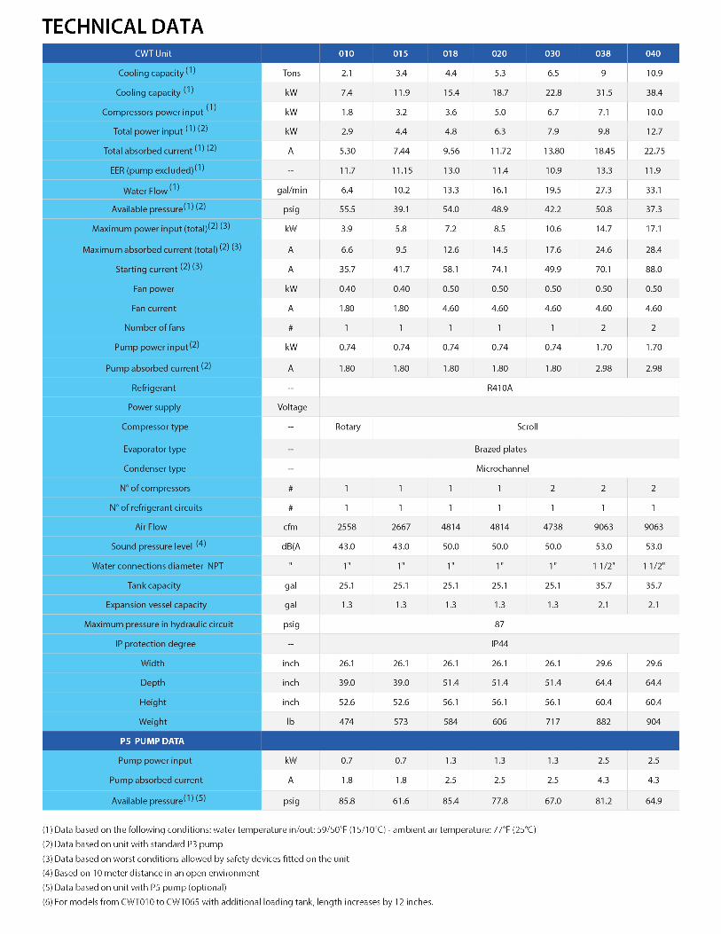
kW
kW
21.3 39.9 43.9 61.9 77.8 94.9 127.4 146.2Cooling capacity
kW
kW
7.2 12.8 14.3 24.2 25.1 32.9 41.6 Total power input
8.7 15.6 17.3 28.7 30.4 38.8 49.7Total absorbed current A
A
A
A
9.4 17.3 18.9 30 34.6 42.3 54.5
10.8 20 21.7 34.2 39.4 47.9 62
55 59.4 65. 8 99 78.9 99 126.8
1.2 1.2 1.2 2.9 2.9 2.9 2.5
Maximum power input (total)
1.6 1.6 1.6 3.7 3.7 3.7 3.4
Maximum absorbed current (total)
# 1 2 2 2 2 2 2 2
6.95
8.12
Starting current
1 2 2 2.9 2.9 2.9 6.9
Fan power
Fan current
kW
1.2 2.4 2.4 3.3 3.3 3.3 8.1
V/Ph/Hz
A
575/3/60
Number of fans
Pump power input
Pump absorbed current
Power supply
5.0 7.1 10.0 16.1 14.0 19.6 30.8kWCompressor power input
5.3 9 10.9 15.6 17.5 21.5 32.2 35.50
11.2
2205
88.8
32.23
44.18
55.12
57.2
67.6
148.1
2.50
3.40
TonsCooling capacity
11.4 13.3 11.9 10.3 10.8 10.32 10.8--EER (pump excluded)
16.1 27.3 33.1 47.1 53.3 65.5 97.3 94.54gal/minWater �ow
48.9 50.8 37.3 45.3 42.5 34.6 55.0 55.2psigAvailable pressure
--
--
--
Compressor type
Evaporator type
Condenser type
--Refrigerant
1.3 2.1 2.1 2.1 3.2 3.2 3.2 3.2galExpansion vessel capacity
87 87 87 87 87 87 87 87psigMaximum pressure in hydraulic circuit
26.1 29.6 29.6 32.8 43.7 43.7 47.6
51.4 64.4 64.4 72.8 79.7 79.7 87.8
47.6
87.8
56.1 60.4 60.4 66.9 74.8 74.8 88.8
606 882 904 1135 1587 1698 2205
1.3 2.5 2.5 4.0 4.0 4.0
2.5 4.3 4.3 7.5 7.5 7.5
77.8 81.2 64.9 71.3 67.1 57.1
inch
inch
inch
lb
kW
A
psig
Width
Depth
Height
Weight
Pump power input
Pump absorbed current
Available pressure
CWT Unit 020 038 040 065 075 090 130 150
Scroll
Brazed plates
Microchannel
R410A
1 2 2 2 4 4 4 4
1 1 1 1 2 2 2 2
#
#
N° of compressors
N° of refrigerant circuits
4814 9063 9063 11060 19382 19382 26006 26006cfmAir �ow
50.0 53.0 53.0 49.5 58.5 58.5 52.0 52.0dB(A)Sound pressure level
IP44 IP44 IP44 IP44 IP44 IP44 IP44 IP44--IP protection degree
1” 1 1/2” 1 1/2” 1 1/2” 2” 2” 2” 2”inchWater connection diameter
25.1 35.7 35.7 35.7 54.2 54.2 54.2 54.2galTank capacity
P5 PUMP DATA
on demand
on demand
on demand
on demand
on demand
on demand

kW
kW
36.1 45.8 54.8 61.5 75.5 92.7 113.1 146.2Cooling capacity
kW
kW
12.9 16.0 20.7 21.9 27.5 31.9 42.0 Total power input
22.67 26.28 33.18 34.06 42.47 49.99 65.04Total absorbed current A
A
A
A
17.6 22.6 26.2 31.9 36.7 43.7 54.5
29.2 34.6 40.3 46.7 54.3 67.9 81.0
61.4 80.1 99 .9 92.2 113.9 145.5 140.6
0.50 1.05 1.05 2.70 2.70 2.70 2.50
Maximum power input (total)
4.60 4.80 4.80 4.20 4.20 4.20 4.20
Maximum absorbed current (total)
# 1 2 2 2 2 2 2 2
6.95
8.12
Starting current
2.50 2.50 2.50 2.50 2.50 6.20 6.20
Fan power
Fan current
kW
4.30 4.30 4.30 4.30 4.30 10.20 10.20
V/Ph/Hz
A
Number of fans
Pump power input
Pump absorbed current
Power supply
9.4 11.4 16.1 14.0 19.6 20.7 30.8kWCompressor power input
10.3 13.0 15.6 17.5 21.5 26.4 32.2 35.50
11.2
2205
88.8
32.23
44.18
55.12
57.2
67.6
148.1
2.50
3.40
TonsCooling capacity
11.9 11.6 10.3 10.8 10.32 12.32 10.8--EER (pump excluded)
31.1 39.5 47.1 53.3 65.5 80.4 97.3 94.54gal/minWater �ow
50.7 48.0 45.3 42.5 34.6 56.9 55.0 55.2psigAvailable pressure
--
--
--
Compressor type
Evaporator type
Condenser type
--Refrigerant
2.1 2.1 2.1 3.2 3.2 3.2 3.2 3.2galExpansion vessel capacity
87 87 87 87 87 87 87 87psigMaximum pressure in hydraulic circuit
32.8 32.8 32.8 43.7 43.7 47.6 47.6
72.8 72.8 72.8 79.7 79.7 79.7 87.8
47.6
87.8
66.9 66.9 66.9 74.8 74.8 88.8 88.8
1102 1102 1135 1587 1698 2161 2205
4.0 4.0 4.0 4.0 4.0 on demand
7.5 7.5 7.5 7.5 7.5 on demand
80.6 75.8 71.3 67.1 57.1 on demand
on demand
on demand
on demand
on demand
on demand
on demand
inch
inch
inch
lb
kW
A
psig
Width
Depth
Height
Weight
Pump power input
Pump absorbed current
Available pressure
CWT Unit 045 055 065 075 090 110 130 150
Scroll
Brazed plates
Microchannel
R410A
460/3/60
3 3 3 4 4 4 6 4
1 1 1 2 2 2 2 2
#
#
N° of compressors
N° of refrigerant circuits
9063 11060 11060 19382 19382 26006 26006 26006cfmAir �ow
53.0 49.5 49.5 58.5 58.5 52.0 52.0 52.0dB(A)Sound pressure level
IP44 IP44 IP44 IP44 IP44 IP44 IP44 IP44--IP protection degree
1 1/2” 1 1/2” 1 1/2” 2” 2” 2” 2” 2”inchWater connection diameter
35.7 35.7 35.7 54.2 54.2 54.2 54.2 54.2galTank capacity
P5 PUMP DATA
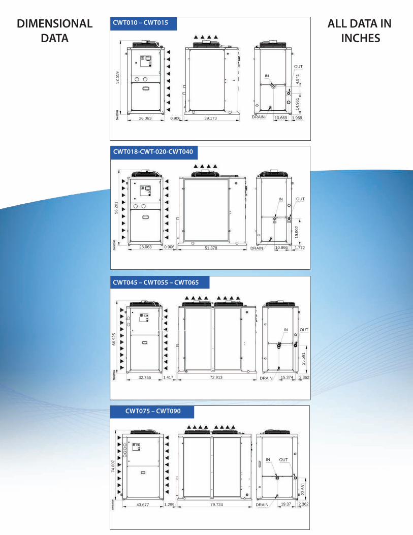
CWT010 – CWT015
CWT018-CWT-020-CWT040
CWT045 – CWT055 – CWT065
CWT075 – CWT090
DIMENSIONALDATA
ALL DATA IN INCHES
26.063 0.906 39.17352
.559
DRAIN 10.669 1.969
14.9
614.
941IN
OUT
26.063 0.906 51.378 DRAIN 10.866 1.772
19.9
02
OUTIN
56.2
01
32.756 1.417 72.913 DRAIN 15.374 2.362
25.5
91
IN OUT
66.9
2566
.925
74.8
07
43.677 1.299 79.724 DRAIN 19.37 2.362
23.6
81
IN OUT

CWT110 – CWT150
47.638 87.795
89.0
94
21.457 2.362
23.6
81
OUTIN
DRAIN1.299
PURESTREAM CHILLER QUOTE REQUEST
Contact NameCompany NamePhone Number Email AddressAddressProvince
CHILLER REQUIREMENTS (Please provide as much information as possible)
Applica
Indoor/Outdoor useCapacity Btuh’s (Ton or KW)Entering chiller temperatureLeaving chiller temperatureAmbient TemperatureFlow USGPMPower RequirementsPump PSI Fluid to be cooledWater %Glycol %Other %
DIMENSIONAL DATA CONTINUED ( All Data In Inches )

Water Cooled Chillers 10 ton (Modular Design)
Spot Coolers: Portable Water & Air Cooled Solu�onsDehumidifiers
Chilled WaterQuick Connect Piping
Air-Cooled Chillers From 1/2 ton to 40 ton
CAG COOLING SOLUTIONS ( A Division of CAG Purification)
3770B Laird Road, Mississauga, ON. L5L 0A7Tel: 800-951-0777 Fax: 905-820-3490
QBS Chill-cube ACW Air Cooled Fluid Cooler
Made in Italy
CWBCWT
Chill-cube Mul�bank
CHILLER SERIESPURESTREAM