Embed Size (px)
Citation preview

L e a c h i n g — M e t a l s A p p l i c a t i o n s
MILTON E. WADSWORTHCollege of Mines and Mineral IndustriesUniversity of UtahSalt Lake City, Utah
9.1 INTRODUCTION
Hydrometallurgy is a relatively recent technology. Modern, large-scale hydrometallurgical processing plantsdepend on electrical power for transport and agitation of large tonnages of ore slurries and solutions.Pumps, agitators, autoclaves, and air compressors of the design needed for hydrometallurgical processingare historically recent developments. Reduction of dissolved metals electrochemically, as in electrorefiningand electrowinning, has broadened the application of hydrometallurgy for separation and recovery. Priorto the availability of electrical energy, reduction from solution was possible using chemical reductants, butrarely on a large scale. A noteworthy example is the reduction of copper contained in acidic mine watersusing metallic iron. Contact reduction of one metal on another, more electronegative metal is commonlycalled cementation. This practice was carried out as early as the sixteenth century in Europe12 and iscommon practice today for recovery of copper from acidic leach liquors.
Leaching refers to the process in which solid ores or concentrates are contacted by an aqueous lixiviantor leach liquor capable of dissolving all or part of the ore or concentrate. The loaded or pregnant liquor isthen subjected to a separation process for purification or recovery or both of desired metals or metalcompounds. The dissolution processes may involve oxidation and reduction or may be simple dissolution,without exchange and reduction or may be simple dissolution, without exchange of charge between thesolid and the lixiviant. In the former, the lixiviant must contain a suitable oxidant or reductant for thedissolution process to occur. Since leaching includes various solution treatment steps, these steps must beconsidered briefly to understand the advent of and expanding role of leaching as a separation process.
9.1-1 Historical
It is quite apparent that reduction of metal in aqueous solutions had to wait for the development of electricalenergy on a commercial scale. Copper was almost a unique exception. Hydrometallurgy therefore followedthe developments of Michael Faraday3 who in 1831 provided the basis that led to the dynamo and toelectrical machinery. Electrical energy was available on a large scale some 40 years later. The first elec-trolytic reduction plant was for copper4 and was constructed near Swansea in 1869.
The sotvent action of cyanide for gold and silver was noted as early as 1783 and cyanidation becamea commercial process following patents by MacArthur and Forrest in 1887 and 1889.5 Reduction of metalsfrom aqueous solutions using hydrogen and other reductant gases was an important development.6"8 Nickeland cobalt have been produced commercially by hydrogen reduction since 1954. The chemistry of gaseousreduction was understood prior to this time. Patents issued between 1906 and 1941 covered the use of SO2,CO, and H2 as gaseous reductants in pressurized vessels. The detailed work of the Ipatievs6 between 1909and 1931 provided the major body of work for high-temperature, high-pressure reduction of metals to the
C H A P T E R 9

metallic or the oxide state in aqueous solutions. Thus, by the early 1900s three methods for the directreduction of metals from aqueous solutions were available to the metallurgical industry: (1) cementation(contact reduction), (2) electrolytic reduction, and (3) gaseous reduction.
In the period 1946-19556 researchers at Sherritt Gordon Mines, Ltd, in Canada and Chemical Con-struction Corporation in the United States developed commercial processes for leaching of nickel and cobaltsulfides and arsenides. Coworkers7 at the University of British Columbia published an important series ofpapers beginning in the 1950s on pressure leaching of sulfides. These advances coupled with research ongaseous reduction led to the development of several commercial processes.7'8 Nonoxidative low-pressureleaching of bauxite was developed by Bayer89 in 1892 and is currently the worldwide method for theproduction of high-purity alumina feed for the Hall Herault electrolytic cell for aluminum metal production.
An important step in many hydrometallurgical processing schemes involves the upgrading of solutionsprior to electrowinning or crystallization. The advent of ion exchange and solvent extraction representedimportant developments for both recovery and upgrading of dilute process streams. Cation exchange onzeolites was first noted in 1876 by Lemberg10 and a significant advance resulted from the work of Adamsand Holmes in 1935 when they developed synthetic ion-exchange resins. Anion exchange became possibleand available on a large scale with increased opportunity for metals extraction. Early attempts in 1945-1950 to recover uranium by cation exchange were not successful. In 1948, however, H. E. Bross success-fully extracted uranium on anion exchangers. The first ion-exchange plant for uranium recovery was builtin South Africa in 1950.10 Similarly, solvent extraction has early origins since it has been used routinelyfor many organic chemical separations. In the 1950s Oak Ridge researchers developed solvent extractiontechniques for recovery of uranium. The first solvent extraction process for uranium was installed in 1955at the Kerr-McGee plant in Shiprock, New Mexico.11 The LIX reagents developed by General Mills werean important development for processing low-grade copper streams. The first (LIX) plant coupling dumpleaching, solvent extraction, and electrowinning was the Ranchers Bluebird Mine in Miami, Arizona,constructed in 1968.11*12
Today, hydrometallurgy is well established as the principal method for extraction of many importantindustrial metals. Hydrometallurgy for the direct treatment of base metal sulfide concentrates, as a widelyused technology, must yet prove itself. The roast-leach electrowinning of zinc is a noteworthy exceptionand is evolving as standard practice in the zinc industry worldwide. Relatively recent developments by wayof jarosite and iron oxide hydrolysis and precipitation processes have improved recovery and helped securezinc hydrometallurgy as standard in the industry.13
There has been a tendency to place hydrometallurgy strictly on a competitive basis with smelting forthe treatment of base metal sulfides. Too many overly optimistic and, in some cases, false claims havebeen made of the relative virtues of hydrometallurgy compared to smelting. Modem smelting plants canmeet the SO2 ambient air requirements by the installation of double contact-acid plants. If hydrometallurgyis to be a competitive technology it must in fact be so in the marketplace with a clear and decisive edge.For this reason it would appear that hydrometallurgy should not be viewed as a competitive technology butsupplemental to and in some cases compatible with smelting. In fact, lower energy versions of hydro-metallurgical processing of base metal sulfides often involve combined smelting and hydrometallurgicalapplications.14 Hydrometallurgy applied to concentrates involves high capital costs, multiple steps, and ingeneral is more energy intensive than is pyrometallurgy.1415 Arguments that hydrometallurgy is nonpol-luting compared to smelting are not persuasive. Effluents may carry heavy metals and must be carefullytreated or impounded. The main throwaway product in the case of hydrometallurgy is gangue plus a mixtureof iron oxides and jarosites and other metal salts as compared with slag from a smelter which is easilystored and relatively nonreactive. Sulfur in smelting is emitted into the atmosphere at accepted levels andgoes to sulfuric acid. In hydrometallurgical processes sulfur goes to sulfate salts or to elemental sulfur.Consequently, there is no clear advantage of hydrometallurgy over smelting when best technology iscompared relative to effluent discharge.
Hydrometallurgy has an increasing role to play in the future. It is unique in its application to low-gradeores which cannot be beneficiated economically. It has distinct potential for in situ extraction of complexsulfide ores and concentrates. It should be viewed as an alternate technology having high chemical speci-ficity. It may be concluded that, with only a relatively short history, hydrometallurgy has become aninportant part of separation technology. There exists a sound basis in theory, materials of construction, andin design capability for its implementation.
9.1-2 Scope of Leaching Practice
Figure 9.1-1 illustrates the general flow of ores and concentrates in leaching practice. Ore usually istransported from the mineral deposit for leaching. In some special cases leaching may occur in situ butthese examples are few and will be treated separately. Normally, the ore is transported and treated bymethods that depend on the value of the ore. It is useful to consider three ore types: low-grade ore, direct-leaching ore, and high-grade ore, the latter being suitable for beneficiation. The major example of theleaching of a low-grade ore is in copper hydrometallurgy commonly practiced in the western United Stateswhere copper is placed on vast leach dumps and is treated by recycling leach solutions. These dumpscontain both sulfides and oxides of such low grade that they are not suitable for beneficiation. Leaching of

SeparationCopperUraniumGold-Silver
Separation SeparationCopper ZincUranium CopperVanadium NickelGold-Silver CobaltAluminum TungstenNickel (Cobalt) PlatinumBeryllium ManganeseTitanium T antalum-NiobiumZinc LithiumMolybdenum Zirconium
MolybdenumFIGURE 9.1-1 Various paths for handling ore in leaching practice.
dumps extends into years and in the best leaching operation achieves approximately a 15-20% ongoing orsteady-state recovery of the new material content being placed on the dump. Heap leaching usually refersto the leaching of oxides and is carried out on prepared leaching pads, with leach cycles of days to months.Uranium, gold, and silver are also leached, though in relatively minor tonnages, by heap-leaching tech-nology. The second type of ore (direct-leaching ore) is one which has sufficient value that it can be crushedor ground to appropriate sizes for vat leaching or agitation leaching. Examples are copper, uranium,vanadium, gold, silver, aluminum, nickel, cobalt, and beryllium. Pretreatment by oxidative, reductive, orsalt roasting may be necessary to render the material suitable for leaching. High-grade ore is of sufficientvalue that it may be beneficiated to increase recovery and produce a concentrate. The concentrates producedmay be pretreated by roasting prior to leaching.
Each process produces a leach liquor which must be treated by some separation process for the recoveryof metal values as metals or as salts requiring further treatment. The various leaching processes produceeither a dilute process stream or a concentrated liquor. Low-grade ores invariably produce dilute processstreams. For example, copper dump-leaching effluents usually contain 0.5-1 g per liter of copper. In thecase of direct-leaching ore, the leach liquor may be either a dilute process stream requiring upgrading ora concentrated stream requiring no additional upgrading. The leaching of concentrates produces a high-grade liquor that can be sent directly to metal recovery by reduction or precipitation. Figure 9.1-2 illustrates
LEACHING LEACHING
LEACHING INPREPARED DUMPS
OR HEAPS
COMMINUTIONAND SIZING
CONCENTRATE
MINERALBENEFICIATION
HIGH GRADE ORESUITABLE FORBENEFICIATION
DIRECTLEACHING
ORE
LOW GRADE ORENOT SUITABLE FOR
BENEFICIATION
RecycledSolution
TRANSPORTEDFOR LEACHING
MINERALDEPOSIT
IN SITULEACHING
RECYCLED SOLUTIONLEACHLIQUOR SEPARATION
HYDROMETALLURGY-LEACHING

FIGURE 9.1-2 Methods employed for separating metals from dilute and concentrated process streams.
the various methods for treating both dilute process streams and concentrated liquors. In the case of diluteprocess streams, metal values may be recovered by either precipitation on other metals through contactreduction or cementation. Examples are recovery of copper by precipitation on iron and recovery of goldby precipitation on zinc. An alternate path is to upgrade the solution to higher concentration levels bymeans of solvent extraction or ion exchange. Important examples are uranium and copper and recently theadsorption of gold and silver on activated carbon. The stripped organic extractant or ion exchanger producesa concentrated liquor. The concentrated liquor may then be suitable for electrowinning directly. Metalssuch as copper, zinc, and gold fall into this category. Often, however, it is necessary to recover theconcentrated metal values from solution either by gaseous or chemical reduction to the metallic state or toprecipitated reduced oxides. Recovery may occur by nonreductive precipitation. Metals following thesevarious paths are indicated in Fig. 9.1 -2.
Many hydrometallurgical processes or process steps are used to upgrade concentrates, process recycledscrap metal, or purify aqueous process steams. Examples are (I) the leaching of molybdenite concentrateto remove impurities:16 (2) leaching of tungsten carbide and molybdenum scrap;17 (3) removal of copperimpurities in nickel anolyte by cementation on metallic nickel;18 and (4) various methods for treatingnuclear fuel elements.
IX-SX
UraniumCopperGold-SilverMolybdenumBerylliumVanadiumMagnesiumActlnldesRare earthsZr-HfNb-TaMo-W-ReNl-Co
CopperZincGoldCadmiumSilverCobaltNickelManganese
UraniumNickelCobaltCopperAluminumMagnesiumBerylliumThoriumLithiumRheniumBoronVanadiumTungstenMolybdenum
Nonreductive Crystallization
SOLVENTEXTRACTION.
ION EXCHANGE
PRECIPITATIONWITHOUT
REDUCTION
NickelCobaltCopperGoldPalladiumPlatinum
CONCENTRATEDLIQUOR
DILUTEPROCESS STREAMS
OH
Gases or SolubleReductants
Cementat ion
GoldCopperCadmiumIndium
PRECIPITATION BYCONTACT
REDUCTION
PRECIPITATION BYCHEMICAL
REDUCTION
L E A C H S O L U T I O N S
S E P A R A T I O N S

TABLE 9.2-1 1978 Copper Production: Statistics for Western U.S. Copper Operations withSignificant Leach Ouput
Copper Production (tons) Percent of TotalCopper Produced
Company Concentrating Leaching by Leaching
Kennecott 287,200 88,200 23.5Phelps-Dodge 283,600 34,550 10.8Duval (Pennzoil) 112,300 10,200 8.3Anamax Mining 67,200 35,810 34.8Asarco 85,780 10,720 11.1Cities Service 72,800 7,750 9.6Cyprus Mines 61,600 12,150 16.5Inspiration Consol. 20,700 18,000 46.5
991,180 217,380 18.0
Source: Reference 1.
9.2 LEACHING PRACTICE
A few examples of leaching practice are presented with the aim of illustrating types of leaching processesrather than an extensive treatise of current practice. The general outline of ore types presented earlier willbe followed.
9.2-1 Leaching of Low-Grade Ores
Table 9.2-1 presents the copper production by major copper producers in the western United States for theyear 1978.! The tonnage produced by dump leaching and the leaching of oxide ores was 18% of total yeartonnage. An estimated two-thirds of this, or approximately 12% of the total, may be attributed to dumpleaching of low-grade predominantly sulfide-waste materials.
In copper dump leaching practice, waste rock (usually below 0.2% copper) is placed on dumps bytruck or rail haulage. These dumps vary greatly in size and shape. Depths extend from a few tens of feetto as much as 1200 ft. It is generally recognized that good aeration is required as well as good permeability.Consequently, the stepped surfaces in the dump are usually ripped to provide needed permeability. As-mined ore, newly placed on a dump, will have permeabilities of approximately 1000 darcys.* Weatheringof intrusive material can cause dramatic changes in porosity. Weathering plus deposition of salts can alsocause significant changes in permeability with time. The impact of such induced weathering is an importantconsideration in assessing expected recoveries, since leaching may extend for years. The porosity of newlydumped rock will be in the range of 35-40% percent, but the weight of haulage trucks can cause compactionof as much as 10 ft in 100 ft. Porosities of as low as 25% may result from compaction and weathering.
Figure 9.2-1 illustrates a dump cross section according to Whiting,2 showing important hydrologicaland structural characteristics.
1. Channeling. Channeling of each liquor occurs as a result of compaction and salt precipitation.Fluid flow down channels essentially bypasses regions of the dump. It is enhanced if solutionapplication is by surface ponding.
2. Seep or Blowout. Compacted zones may cause entrapment of solutions, resulting in the formationof a perched water table within the dump. The buildup of hydrostatic pressure can cause surfaceseepage and even expulsion of solid material from the dump wall.
3. Stratification. During the dumping of waste rock, the coarse material travels further down theslope or the dump than the fine material, causing stratification. Without appropriate ripping, strat-ification may affect the flow pattern within the dump.
4. Sorption. Solutions bearing dissolved metals may pass through regions containing nongravitationalwater at lower concentrations. Trapping of metal values can occur by inward diffusion into the porestructure of the rocks and into stagnant aqueous regions.
5. Aeration. Aeration is best near the face of the dump, providing optimal conditions of temperatureand bacterial activity. Aeration by convection through the dump is an essential part of the leachingmechanism. In regions of high oxidation potential, iron is oxidized by bacterial activity to the ferricstate resulting in the precipitation of ferric oxides and jarosites.
*Darcy refers to hydraulic conductivity or permeability. Permeability in cm/s is converted to darcys bymultiplying by 1045.

6. Seepage Losses. Seepage can occur through the foundation of the dump, although the formationof salts and the presence of fines often keeps this at a surprisingly low level. Runoff waters mayalso recharge or dilute the percolating liquors through the foundation of the dump.
In practice, dump leaching depends on sequence of processes. Within the dump three conditions areessential for leaching to occur and continue. These are:
Effective air circulationGood bacterial activityUniform solution contact with the particle
The major unknowns in dump leaching for any given dump are:A knowledge of air circulation relative to the dump configurationThe hydrology in terms of channeling and bypassThe effect of fines and precipitated saltsThe effect of weathering as a function of time
Figure 9.2-2 illustrates the general flow of solution to the dump, to a holding basin, and to copperextraction. Copper extraction is achieved either by cementation on detinned scrap iron as indicated or bysolvent extraction using one of the LIX reagents for selective removal of cupric ion from sulfate leachliquors. The general trend is toward solvent extraction due to the high costs of iron scrap. Schlitt1 hasindicated that the operating costs for solvent extraction are less than those for cementation, although thecapital costs may be higher. Also, solvent extraction-electrowinning produces a marketable copper cathode.
Following extraction, solutions are recycled or enter a containment pond where some aeration occurs.It should be noted, however, that the iron balance for the greater part is achieved by precipitation of ironsalts throughout the dump itself, as hydrated oxides or jarosites. In general, intermittent leaching withalternate leach and rest cycles is preferred to continuous leaching.3 This practice conserves energy consumedin pumping and is effective since pore leaching continues during the rest period, under conditions of goodaeration, building up dissolved metal values in the liquid phase. Continuous leaching without the rest cycle.
T Y P I C A L W A S T E D U M P S E C T I O N
FROMPRECIPITATION/RUNOFF
LEACH SOLUTION &PRECIPITATION
STRATIFICATION(Controls Flow)
COMPACTED ZONE"(Haulage Trucks)
SEEPORBLOW-OUT
SULFIDE OXIDATION ZONE— HIGH TEMP - BACTERIALS, ACTION
OXYGEN ENTRY
BACTERIAL ACTION ~"SALT DEPOSITION ZONE
(Barrier)
PREGNANT SOLUTION /COLLECTION DAM & POND
(Lined)
SEEPAGELOSS
RECHARGE
NOTE:ACID+ ROCK = CLAYSx
WATER + ROCK = SALTS
FIGURE 9.2-1 Cross section of copper leach dump illustrating physical and hydrological features. (Re-produced from Whiting.2)
TRAPPED _ZONES
BORPTIOW
BEDROCKAND/ORSOIL-N
Ic HANNEL

FIGURE 9.2-2 Flow of leach liquors in copper dump leaching.
because of the large volume of water, extracts large quantities of heat from the dump (up to one-half ofthe exothermic heat of reaction), adversely affecting leaching rates.
Of special importance is the method of solution application.2'3 The general methods employed are:
1. Pond irrigation.2. Trickle.3. Low-pressure multiple sprays.4. High-pressure single spray.5. Well injection.
The trend in dump leaching is toward trickle leaching or sprays. In ponding, channeling can causeexcessive dilution with loss of control over effluent quality. Trickle leaching is carried out by using anetwork of perforated PVC pipe. This system provides a more gradual application of solutions and moreuniform air and solution access to the dump. Spraying, using low-pressure multiple sprays or high-pressuresingle sprays, also provides uniform coverage. Spray systems may suffer excessive solution loss by evap-oration in areas having high evaporation rates. Both trickle and spray leaching suffer in some areas whereexcessive ice formation may occur during winter months. In such cases more than one method of solutionapplication may be needed. The last method is injection down wells. This is the method used in uraniumsolution mining. Wells are drilled on a grid pattern and lined with perforated pipe. Solution flow is controlledby combined down-well and up-well pumping through a flooded formation. Percolation leaching using thismethod for copper recovery suffers because uniform coverage is difficult. Solutions move generally down-ward under free-flow conditions, requiring a close network of injection wells for adequate coverage. Thismethod has been used by Anaconda in Butte, Montana, where ice formation is a serious problem.
Jackson and Ream3 recently reviewed the results of an extensive field test study at Kennecott's BinghamMine. A comparison was made between trickle and spray leaching. In general, spray leaching resulted ineffluent solutions containing somewhat high concentrations of copper, illustrating the importance of uniformcoverage with minimal channeling. In typical dump-leaching practice, the solution application rate differsfrom the irrigation rate, since the latter includes the rest portion of the total rest cycle.3 The applicationrate is the leach solution flow rate per unit area of surface to which it is being applied, typically \ to 5 ofthe total area available for application. On the average, application rates observed to give the best resultsvary from less than 5.56 x 10~6 m3/m2-s (0.5 gal/ft2-h) for sprinklers, to 2.22 x 10"6 m3/m2-s (2 gal/tf-h) for trickle leaching. For pond leaching, the application rate may be as high as 5.56 X 10"5 m3/m2-s(5 gal/ft2 *h). The irrigation rate is the total dump-system solution flow rate divided by the total surfacearea available for solution application.
It is uneconomical to remove salts from leach liquors before recycle. Usual practice is to add make-upwater as needed and in some cases sulfuric acid. The solutions will build up in metal and sulfate concen-tration until salt deposition occurs. Iron is soon in equilibrium with a variety of jarosite salts, dependingon the general chemistry of the dump system. Aluminum and magnesium can increase to very high values,for example, 5-10 g/L, and sulfate concentrations may approach 1 M. In general, a successfully operatingsulfide leach dump is capable of generating acid internally; that is, a dynamic buffering effect, balancingacid-producing and acid-consuming reactions, must produce pH values and solution oxidation potentialsconducive to the promotion of bacterial activity and solubilization of copper and iron in solution. Acidadditions to influent leach liquors do not alter the balance of acid-consuming and acid-producing reactionsof such massive systems but serve to prevent precipitation of iron salts in the upper strata of the dump,preserving adequate permeability for uniform solution penetration.
The steady-state generation of ferric iron, in all of its soluble forms, Fe(III), and hydrogen ions is of
CEMENTATION IRON SALTS
SOLVENT EXTRACTION
HOLDINGBASIN
COPPEREXTRACTION
AERATIONPONO
OUMP
MAKE UPACIO, WATER

primary importance in an acid dump-leaching system. At 300C the solubility of oxygen in pure water is2.3 x 10~4 mol/L. In the high-ionic-strength liquors produced in recycled leach liquors, the solubility isconsiderably less. As may be shown, the oxygen oxidation of sulfide minerals is kinetically less importantthan oxidation by complex ferric ions in solution, present in much greater concentration. Oxygen is essential,serving to oxidize ferrous iron to ferric and to provide conditions for the growth of chemoautotrophicbacteria.
Normally, the oxidation of ferrous iron to ferric is slow. The bacterium Thiobacillus ferrooxidans, anaerobic chemoautotroph deriving its energy from the oxidation of ferrous iron, greatly accelerates theoxidation of ferrous iron according to the reaction
(9.2-1)
Oxygen is essential to the metabolic cycle of the bacteria. The bacterium Thiobacillus thiooxidans is alsoan aerobic chemoautotroph deriving its energy from the oxidation of elemental sulfur, thiosulfate, or sulfideas contained in heavy metal sulfides. Sulfur oxidation produces sulfuric acid in place, an essential featurein maintaining open porosity in dump leaching. Pyrite is a strong acid producer, supplying ferrous ironwhich is subsequently oxidized to the ferric state in the presence of 71 ferrooxidans. Pyrite also greatlyinfluences the net consumption of oxygen in the system which often may be as high as 7-20 moles ofoxygen per mole of Cu2+ produced.
Ferric iron in solution exists in several forms. The more important forms are Fe(SO)2", FeSO^,FE2(OH)2+, and FeOH2+. The sulfate complexes are greatly favored over the hydroxyl complexes.4 Toillustrate the importance of iron complex formation, a typical leach solution will be considered in equilibriumwith precipitated hydrogen jarosite, having an approximate free-sulfate activity of 0.02. The equilibriumis represented by
(Fe)3(SO4MOH)5-2H2O + 5H+ = 3Fe3+ + 2SO2T + 7H2O (9.2-2)
for which log K — —2.7. The iron sulfate complex equilibria are
Fe3+ + SO?" - FeSO4+ (9.2-3)
and
Fe3+ + 2SOj- - Fe(SO4)2" (9.2-4)
with log K values of 4.15 and 5.4, respectively. Accordingly, at pH = 2.3, the ferric ion activity wouldbe approximately 8.6 x 10"5. Using activity coefficients of approximately 0.7, the corresponding ferricsulfate complex concentrations of FeSO^ and Fe(SO4)^, respectively, would be 0.035 and 0.012 M. Thiscorresponds to a total maximum Fe(III) concentration of approximately 2.6 g/L at this pH. Under conditionsof dump-leaching, ferric ion complexes are present with activities much greater than the activity of dissolvedoxygen and are kinetically more important than oxygen in the mineral oxidation. In the total dump-leachingsystem, the oxidation sequence is:
1. Aeration by convection, promoting bacterial activity.2. Oxidation of ferrous iron to ferric.3. Ferric iron dissolution of sulfides with metal release and acid generation.
The dissolution reactions typically of importance in copper dump leaching are:
Chalcopyrite (CuFeS2) Oxidation
CuFeS2 + 4Fe(III) = Cu2+ + 5Fe(II) + 2S° (9.2-5)
Chalcocite (Cu2S) Oxidation
Cu2S + 2Fe(III) = CuS + Cu2+ + 2Fe2+ (9.2-6)
Covellite (CuS) Oxidation
CuS + 2Fe(III) = Cu2+ + 2Fe2+ 4- S0 (9.2-7)
Somite (Cu5FeS4) Oxidation
Cu5FeS4 + 12Fe(III) * 5Cu2+ + 13Fe2+ + 4S° (9.2-8)

Sulfur Oxidation
bac
S0 4- H2O + i.5O2 = H2SO4 (9.2-9)
Pyrite (FeS2) Oxidation
FeS2 + 14Fe(III) + 8H2O = 15Fe2+ 4- 2H2SO4 4- 12H+ (9.2-10)
Pyrite is a strong acid producer. The bacterial oxidation of Fe(II) to Fe(III) [Eq. (9.2-1)] is acidconsuming. When coupled with pyrite oxidation, the net result is the formation of 1 mole of H2SO4 permole of pyrite oxidized to sulfate. This is possible only in the presence of bacteria under conditions ofgood aeration. Hydrolysis reactions forming precipitated salts such as Eq. (9.2-2) are also acid producing.
Many gangue mineral reactions are acid consuming, resulting in a dynamic steady-state pH suitable tosupport bacteria and maintain open porosity. Important acid consuming reactions are:
Malachite
CuCO3Cu(OH)2 + 4H+ = 2Cu2+ + CO2 + 3H2O (9.2-11)
Azurite
2CuCO3 Cu(OH)2 + 6H+ = 3Cu2+ + 2CO2 + 4H2O (9.2-12)
Chrysocolla
CuOSiO2-2H2O 4- 2H+ = Cu2+ 4- SiO2 4- 3H2O (9.2-13)
Calcite
CaCO3 + 2H+ 4- SOj- + H2O = CaSO4 • 2H2O + CO2 (9.2-14)
Chlorites
H2Mg2Si2O9 VH4Mg2Al2Si2O9 + (6 + 6y)H+
= (2 4- 2y)S\O2 4- (3 4- 2y)Mg2+ + 2y Al3+ + (5 + Sy)H2O (9.2-15)
Biotite
H2K(Mg)3^(Fe)6 _3xAl(SiO4)3 + 1OH+
= K+ 4- 3JcMg2+ -I- (6 - 3.T)Fe2+ + Al3+ + 3SiO2 + 6H2O (9.2-16)
K-Feldspar Alteration to K-Mica
3KAlSi3O8 4- 2H+ 4- 12H2O = KAl3Si3O10(OH)2 4- 2K+ + 6H4SiO4 (9.2-17)
K-Mica Alteration to Kaolinite
2KAl3Si3O10(OH)2 4- 2H+ = 3Al2Si2O5(OH)4 4- 2K+ (9.2-18)
Kaolinite
Al2Si2O5(OH) + 6H+ = 3Al3+ 4- H2O -I- 2H4SiO4 (9.2-19)
Expected recovery from massive dumps is not known. Steady-state daily recovery, the fraction of thedaily tonnage of copper added to a dump which is recovered by leaching, generally falls in the range of15-20%. For example, at Kennecott, Bingham, Utah, 250,000 tons of ore (0.17% copper) goes to thewaste dump daily. This ore contains approximately 850,000 lbm of copper of which 150,000 lbm or 18%is recovered daily.
U.S. Bureau of Mines researchers pioneered the commerical implementation of heap leaching appliedto low-grade gold-silver ores and have demonstrated that agglomeration by the use of Portland cement,added in amounts of up to 10 Ib1n per ton of feed, can improve the percolation rate of leach liquors

significantly.56 Pilot-plant studies have demonstrated improved uniform percolation rates with increasedmetal recovery. Also, Bureau of Mines researchers7 have promoted earlier technology8 for gold recoveryfrom heap-leaching solutions by adsorption of gold cyanide complexes on activated carbon. This technologywas first applied commercially by Smokey Valley Mining Company in 1977.9
9.2-2 Direct Leaching Ore
Direct-leaching ores are those having sufficient value that they can be sized and subjected to leaching instirred reactors (pachuca or agitation) or by percolation (vat leaching). Important examples of direct-leachingores are bauxites treated by the Bayer process, gold ores suitable for slime leaching, nickel laterites fornickel and cobalt recovery, and acid and base leaching of uranium ores. All these ores will experienceexpanding use of hydrometallurgy in the future.
Gold leaching has experienced some important recent developments7'l0 and is an excellent example ofoxidation leaching. An important development in gold leaching has been the reintroduction of older tech-nology in the form of the carbon-in-pulp process.1112
The following steps occur in the carbon-in-pulp process:
Oxidative Leaching
2Au + 4CN- +O 2-H 2H2O = 2Au(CN)2" + 2OH" + H2O2 (9.2-20)
Adsorption (Ion Exchange)
C-OH + Au(CN)2- = C-Au(CN)2 + OH" (9.2-21)
Hot Caustic Stripping
C-Au(CN)2" + OH" = C OH + Au(CN)2" (9.2-2)
Electrolysis
e~ + Au(CN)2" = Au0 + 2CN" (9.2-23)
The leaching step, Eq. (9.2-20), produces gold cyanide anion in, solution which is adsorbed on an ion-exchange site on the surface of activated carbon as indicated in Eq. (9.2-21). The surface-active site onthe activated carbon (C-OH) is depicted here as an ion-exchange site. The actual mechanism is stilluncertain. Hot caustic stripping, Eq. (9.2-22), produces a high-grade gold stream suitable for recovery ofgold by electrolysis, Eq. (9.2-23). The flowsheet of the Homestake Mining Company carbon-in-pulp processis illustrated in Fig. 9.2-3." The process permits the countercurrent flow of activated carbon to each liquor.Following stripping, the carbon must be reactivated by a thermal treatment. The need to treat more difficultgold ores has resulted in the development of innovative new methods of separation.12
The Bayer process has similarly experienced significant change in recent years. It is an excellent exampleof large-scale, nonoxidative pressure leaching. Changes in Bayer process technology have resulted mainlyfrom the need to treat more refractory ores. Bauxite ore types are important since the difficulty of digestiondepends on the form of the hydrated aluminum oxide present. Aluminum in bauxite usually exists in oneof three forms:13
Gibbsite (7Al(OH)3)Boehmite (7AlOOH)Diaspore (aAlOOH)
and in addition contains iron to variable degrees. Bauxite ores high in gibbsite are less costly to treatbecause of the relative ease of dissolution of gibbsite. Bauxites containing the monohydrated minerals inlarge quantity are more difficult to leach, require higher temperatures and pressure for complete digestion,and are more costly to treat. Consequently, bauxites may be classified as low cost or high cost. Althoughthe majority of the bauxite processed is low cost (high gibbsite), this type is estimated to constitute only12% of total bauxite reserves.13
The cost of capital equipment for a Bayer processing plant is related to the amount of monohydratedalumina present (boehmite or diaspore) and to the amount of iron oxide present. The first relates to therefractory nature of ore and the second to the amount of material that must be handled and separated. Hilland Robson14 have estimated capital cost ratios for Bayer plants treating various types of bauxite ore.Capital costs of a bauxite containing 50% of the alumina as the monohydrate are estimated to be 40%higher than for a typical low-cost bauxite.
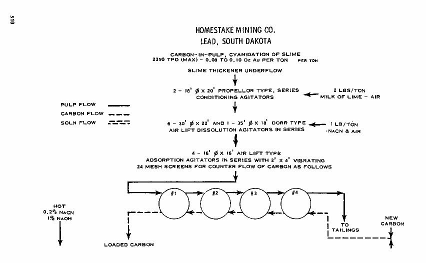
HOMESTAKEMININGCO.
LEAD, SOUTH DAKOTA
CARBON-IN-PULP, CYANIDATION OF SLIME2350 TPO IMAX) - 0.08 TO 0. 10 Oz Au PER TON PER TON
SLIME THICKENER UNDERFLOW
2 - 18* 0 X 20* PROPELLOR TYPE. SERIES ̂ __ 2 LBS/TONCONDITIONING AGITATORS * ^MILK OF LIME - AIR
6 - 301 0 X 22* AND 1 - 35* 0 X 18* DORR TYPE ^ , LB/TONAIR LIFT DISSOLUTION AGITATORS IN SERIES -NACN & AIR
4 - ! 8 1 ^ X 16' AIR LIFT TYPEADSORPTION AGITATORS IN SERIES WITH 2* X V VIBRATING
24 MESH SCREENS FOR COUNTER FLOW OF CARBON AS FOLLOWS
PULP FLOWCARBON FLOWSOLN FLOW
HOT0.2*6 NACN
\% NAOH
LOADED CARBON
TOTAILINGS
NEWCARBON

DESORPTION VESSELS
HIGH GRADE LIQUOR
ELECTROLYSIS
BARREN SOLUTIONRECYCLE
FIGURE 9.2-3 Carbon-in-pulp process for recovery of gold at Homestake Mining Company. (Reproducedfrom McQuiston and Shoemaker.11)
GOLD - SILVERSPONGE
TOREFINERY
STRIPPED CARBON
THERMAL REACTIVATION KILN
SCREEN 120 MESH)
OVERSIZERECYCLE
UNDERSIZE
REFINERY

The Bayer process involves the following steps:
1. Nonoxidative dissolution of hydrated aluminum minerals.2. Solid-liquid separation to remove ferric oxide, silica, and silicates.3. Cooling, seeding, and precipitation of gibbsite, Al(OH)3.4. Calcining of gibbsite to produce pure Al2O3.
The chemical reactions involved in dissolution are
Al(OH)3 + NaOH = Al(OH)4" H- Na+ (9.2-24)
AlOOH + NaOH + H2O » Al(OH)4- 4-Na+ (9.2-25)
Ores containing essentially pure gibbsite may be digested at temperatures of 1500C while boehmitic oresrequire temperatures in the range of 230-25O0C. These temperatures reflect the differences in the solubilitiesof the various hydrated aluminum minerals. Figure 9.2-4 illustrates a typical Bayer process flowsheet.
Nickel laterites represent an important example of direct-leaching ores. In 1924 Caron obtained a U.S.Patent for a hydrometallurgical process for treating nickel laterites.15 The process involves the use ofammoniacal ammonium carbonate leach solutions for the dissolution of an iron-nickel alloy produced in areductive roast pretreatment step. The leaching takes place at atmospheric pressure with oxygenation byair. This process became the Nicaro process, first used in Cuba in 1944.l6 An alternate process was alsointroduced in Cuba at Moa Bay. It involved sulfuric-acid pressure leaching of contained NiO and is suitablefor low-acid-consuming ores. Power and Geiger'7 reviewed the application of the ammoniacal ammoniumcarbonate (AAC) leaching process worldwide. Of 16 plants listed, 8 used hydrometallurgical processing.One of these is the Moa Bay pressure-leaching process and the other 7 use the AAC process based on theoriginal technology developed by Caron. In the Caron process nickel carbonate is precipitated. In variousmodifications, the carbonate may be reduced by coke to a highly metallized sinter or may be simply calcinedto NiO. A modification proposed by Sherritt Gordon17 produces metallic nickel by autoclave hydrogenreduction and is the basis for the Marinduque Surigao Nickel Refinery.18 Recently, Amax19 introduced acombined high-pressure and atmospheric-pressure acid-leach process capable of treating both limonitic andgarnierite-type ores. Dissolved nickel and cobalt are precipitated as sulfides. Hydrometallurgy applied tothe leaching of nickel laterites undoubtedly will continue to be an important method for the treatment ofnickel laterites.
The AAC process consists of the following steps:17
Gaseous Reduction
NiO + H 2 -* Ni0 + H2O (9.2-26)
3Fe2O3 + H 2 -* 2Fe3O4 + H2O (9.2-27)
where the Ni0 is an alloy containing reduced iron.
Ammoniacal Oxidizing Leach
Ni(Fe) + O2 + 8NH3 + 3CO2 + H2O - Ni(NH3)I+ + Fe2+ 4- 2NH4
+ + 3CO2T (9.2-28)
Iron Precipitation
4Fe2+ + O2 + 2H2O + 8OH" - 4Fe(OH)3 (9.2-29)
Ammonia Removal and Nickel Precipitation
steam
Ni(NH3)I+ + 2CO2 4- 2OH" —> Ni(HCO3)2 I + 6NH3 T (9.2-30)
strip
Calcining
mast
Ni(HCO3), — NiO+ CO2 t + H2Ot (9.2-31)
Reduction
NiO + C(coke) = Ni0 + CO (9.2-32)

Alumina
FIGURE 9.2-4 Bayer process for recovery of high-purity AI2O3 from bauxite ores.
In the process, cobalt is removed by precipitation as a sulfide containing a high Ni: CO ratio (Ni: Co >500). Figure 9.2-5 illustrates the flowsheet of the Townsville17 process.
Uranium slurry leaching is a standard technology for the treatment of uranium ores. Uranium may beleached in acidic solutions or in basic solutions since the uranyl ion will form complexes with both sulfateand carbonate ions. Uranium in the reduced U(IV) state, as in pitchblende and uraninite, must be oxidizedto the U(VI) state, producing the divalent uranyl ion in solution which will form sulfate and carbonatecomplex anions. The majority of the uranium leaching plants use acidic leach solutions and may be operatedat atmospheric pressure. Chemical oxidants such as sodium chlorate or manganese dioxide are added tooxidize U(IV) to U(VI). These oxidants couple effectively with the Fe(III)/Fe(II) naturally present is mostores. Carbonate leaching is suitable for high-acid-consuming ores, but the reaction is slow at ambient
Ca(OH)2
Bauxite ore Na2CO3
Crusher &grinder
Slurry mixer
Autoclaves
Flash tanksCausticsolution
Mudthickeners
Red mudFilter
Na2CO3
Evaporation Filters Ball mill
Cooling tank Scrubber
Sinter kilnPrecipitatorsAlumina
seed
ThickenersWater
Ball mill
Rotaryfilters
Brown mud
DisposalHydratewasherWashings
Calcining kilnSodium aluminate
solution
Cooler
Limestone

tailingsto waste
FIGURE 9.2-5 Townsville flowsheet for recovery of nickel from laterite ores. (Reproduced from Powerand Geiger.l7)
pressure. Pressure leaching is commonly used with oxygen as the lixiviant. The chemistry and technologyfor uranium treatment are now some 30 years old and have experienced a variety of important changes inthe intervening period. Most noteworthy were the application of anion-exchange resins and the introductionby Oak Ridge researchers of a solvent extraction process for the upgrading of uranium leach liquors. Theores containing vanadium usually are leached on the acid side if high recoveries of vanadium are desired.In general, the process involves either acidic or basic carbonate dissolution, upgrading of solutions bysolvent extraction or ion exchange, stripping, and precipitation of uranium salts.
Acidic and basic dissolution of uraninite (UO2) is depicted below as an example of U(IV) leaching.Similar reactions may be written for pitchblende (U3O8). Uraninite and pitchblende are the two mostimportant uranium minerals. The leaching of oxidized [U(VI)] uranium minerals such as carnotite,K2O-2UO3'V2O5-3H2O, is readily achieved in both acid and basic circuits since oxidation is not required.Oxidation-leaching processes are rate limited by the oxidation step.
ACID LEACHING (MnO2-Fe(ll/lll) COUPLED OXIDANT)
UO2 + 3HSO4" + 2Fe3+ = UO2(SO4)?- + 3H+ + 2Fe3+ (9.2-33)
2Fe2+ + 2MnO2 + 4H+ = Mn2+ + 2Fe3+ + 2H2O (9.2-34)
crushedwet ore
dryers
fueloil
grindingplant
hotcombustion
gasesfueloil
reduct ionroast
ammonialeach ^liquor***-
quench tanks
aerators
H2S
sulphidereactor
. f i l t e r Ni/CoSproduct
productthickener
NH 3
liquid/solidseparation "
basic, nickelcarbonate
calciner
NiO
coke,.Sintering
furnace
nickelsinter
product
ammoniastripper
I
steam
strippedIiquor
. productslurry
liquorto waste
-ammoniastrippers
fuelo i l -
washedtailings
, freshammonia
I iquorsteam
- washingthickener -
high
-air
Tleachingthickener
solidsunderflow NH 3ZCO 2
absorbers
productliquor

Carbonate (Oxygen) Leaching
UO2 + 0.5O2 + 2HCO.̂ + CO2T = UO2(CO3)J- + H2O (9.2-35)
In the carbonate, basic leaching process, both carbonate and bicarbonate ions are required to buffer thesolution and prevent precipitation of uranium salts. In both acidic and basic leaching, complex anions areformed. The solutions may therefore be upgraded by anion exchange or anion solvent extraction (SX)processes. The upgraded solution is normally treated by selective precipitation of uranium by pH adjustment.
URANIUM PRECIPITATION:Uranium is recovered by pH adjustment between 5 and 6, causing precipitation of a mixture of uraniumsalts including diuranates, hydrated oxides, and basic uranyl sulfate.20 The ammonium hydroxide precipi-tation reaction of the diuranate salt is
2UO2SO4 + 6NH4OH - (NH4)2U2O7 i + 2(NH4)2SO4 + 3H2O (9.2-36)
Uranium may also be precipitated as a peroxide using hydrogen peroxide
UO2SO4 4- H2O2 + 2H2O = UO4 -2H2O + H2SO4 (9.2-37)
Figure 9.2-6 illustrates the features of an acid leach circuit.20
Table 9.2-2 summarizes the various methods used for the treatment of direct leaching ores. Typicalminerals are listed, and those that can be leached by nonoxidative dissolution (NOX) are indicated. Thoserequiring oxidants (OX) are also indicated. In some cases pretreatment is required, as in the case of reductionroasting of nickel laterites or vanadium ore which may be subjected to an oxidative salt roast prior tononoxidative dissolution. Also indicated in Table 9.2-2 are the typical lixiviants used in the process, themethods used for metal recovery, and the form of the final product produced.
9.2-3 High-Grade Ores
High-grade ores are those which may be economically beneficiated to produce a concentrate prior toleaching. Examples of such concentrates are iron-nickel sulfide in the case of the Sherritt Gordon Process,roasted zinc sulfide concentrates, standard in the roast-leach-electrowinning practice for zinc recovery, zincsulfldes in the case of the new Sherritt Gordon Cominco pressure leaching process,21 and flotation andgravity concentrates for gold recovery by cyanidation. Recovery of gold from concentrates and roast-leach
Ore Water
Grinding
Dewatering
LeachingStage I
Slurry Liquid-SolidSeparation
PregnantSolutionRecycle Acid
Oxidont
SlurryLeachingStage 2
Water or-RecycledSolutions
Liquid-SolidSeparationSolution
Slurry
Tailings
FIGURE 9.2-6 Simplified flowsheet for recovery of uranium by acid leaching. (Reproduced from Mer-ritt.2°)

TABLE 9.2-2 Direct Leaching Ores, Indicating General Methods of Treatment
Method of Metal FinalMineral Lixiviant Recovery Product
Oxidized CopperCuCO3Cu(OH)2, malachite NOX acid Electrowinning Metallic copper2CuCO3Cu(OH)2, azurite NOX acid Electrowinning Metallic copperCuSiO3 • 2H2O, chrysocolla NOX acid Electrowinning Metallic copperAluminum Oxides
Al(OH)3, AlOOH, bauxite NOX caustic Precipitation Al2O3
and roastUranium OxidesUO2, uraninite OX acid, base Precipitation Oxidized saltsU3O8, pitchblende OX acid, base Precipitation Oxidized saltsK2(UO2)2(VO4)2-(1-3)H2O, carnotite NOX acid Precipitation Oxidized saltsCa(UO2)2(VO4)2-(5-8)H2O, tyuyamunite NOX acid Precipitation Oxidized saltsU(SiO4), _Jt(OH)4̂ , coffinite NOX acid, base Precipitation Oxidized saltsCa(UO2)2(SiO3)2(OH)2, uranophane NOX acid, base Precipitation Oxidized saltsNickel Laterite(FeNi)O(OH) • nH2O, limonitic RR-OX or Precipitation NiO, metallic
laterite NOX AAC acid OrH2 nickel,reduction sulfidesprecipitation
NiO substitution, nickeliferous silicates RED-OX AAC Precipitation NiO, metallicnickel
Gold-SilverFree leaching ores, metallic Au, Ag OX caustic Precipitation, Metallic
electrowinning Au, AgVanadiumUranium ores and SR-NOX water Precipitation Oxide
vanadiferous clays
NOX = Nonoxidative dissolution.OX = Oxidative dissolution.
AAC = Ammoniacal ammonium carbonate.RR = Reductive roast.SR = Salt roast.
electrowinning applied to zinc represent commercial processes used throughout the world. The applicationof hydrometallurgy to the treatment of conventional base metal sulfide concentrates has not emerged as apromising new technology. Even if various smelter sulfide intermediates are included as feed materials,the total number of plants treating such materials remains few in number.
The Sherritt Gordon process is historically important as the first commercial application of hydromet-allurgy to the recovery of nickel from sulfide concentrates.22 The primary mineral is pentlandite, (Fe, Ni)S,associated with pyrrhotite, FenSi2. The concentrate is produced at Lynn Lake, Manitoba, and is processedin Sherritt Gordon's plant at Fort Saskatchewan, Alberta, Canada. The concentrate contains approximately10% nickel and is treated by pressure, autoclave leaching using air as the oxidant. Leaching is based onthe formation of soluble amine complexes of the form (Me(NH3)^)"+, where Me may be Ni, Co, Cu, Zn,or Fe(II). The steps in the process are leaching, copper removal, oxidation and hydrolysis of soluble sulfurintermediates, and nickel reduction using gaseous hydrogen. The effluent aqueous stream is treated forcobalt recovery.
Leaching is carried out in two stages with excellent recoveries under the conditions 344-360 K (160-19O0F) and 6.9 x Kf-l.O x 106 N/m2 (100-150 psig). The leaching reactions are
NiS + 6NH3 + O2 = Ni(NH3)J+ + SO2T (9.2-38)
4FeS + 9O2 + 8NH3 + 4H2O = 2Fe2O3 + 8NH4+ 4SOa" (9.2-39)
All sulfur is shown to convert to sulfate ions in solution. Under the conditions of leaching, much of thesulfur remains in solution as metastable soluble intermediates. Oxidation of sulfur occurs in the sequence:thiosulfate ions, S2O3"; thionate ions, SnOl'; sulfamate ions, SO3NH2"; and sulfate ions, SOi". Thepartially oxidized sulfur ions in solution must be converted to sulfate ions prior to nickel reduction tomaintain nickel purity. One of the important features of the pressure-leaching process is the concurrent

Ni-Co SULFIDES TOCOBALT RECOVERYFIGURE 9.2-7 Sherritt Gordon pressure leaching process for recovery of nickel from nickel concentrates.
precipitation of iron as Fe2O3 during leaching and subsequent iron removal by thickening and filtration.The leaching circuit is illustrated in Fig. 9.2-7.
Pregnant solution from the leaching circuit contains typically 40-50 g/L nickel, 0.7-1.0 g/L cobalt, 5-10 g/L copper, 120-180 g/L ammonium sulfate, 5-10 g/L sulfur as thiosulfate and polythionates, and 85-100 g/L free ammonia.1 Copper removal requires initial removal of ammonia followed by precipitation ofcopper in the form of copper sulfides. The unoxidized sulfur in solution assists in the precipitation process.Removal of ammonia by steam injection releases cupric ions to react with these sulfur compounds, asshown by the reactions:
Cu2+ + S2O?" + H2O * CuS + 2H+ + SOj" (9.2-40)
Similar reactions occur with dithionates and polythionates in solution. Final copper residuals are strippedusing H2S under modest pressure. Aqueous effluent from copper removal is heated to 490 K (425 0F) and
SOLUTION TO AMMONIUMSULFATE RECOVERY
COBALT REDUCTIONEND SOLUTION H2S PRECIPITATION
FILTRATION
H2S-
NtCKEL POWDERAND
BRIQUETTES
NICKEL REDUCTIONEND SOLUTION
HYDROGENCATALYST NICKEL REDUCTION
LIQUID-SOLJDSEPARATION
POWDER WASHING
AIR EXIT GASOXIDATIONHYDROLYSIS
Cu SULFIDE"BY-PRODUCT-Cu-Ni SULFIDES TOFIRST-STAGE LEACH
H2S
AMMONIADIST ILLATION
COPPER REMOVALCOPPER STRIPPING
TAILINGS TO POND
FINISHEDLEACH SOLUTION
SECOND-STAGEAMMONIA LEACH
LIQUID-SOLIDSEPARATION
AIRAMMONIA
PARTIALLYSPENT AIR AMMONIA AQUA TO
SECOND-STAGE LEACH
LEANLIQUORRECYCLE
FIRST-STAGEAMMONIA LEACH
LIQUID-SOLIDSEPARATION
NICKEL AMMONIUMSULFATE RECYCLEFROM COBALT PLANT
RESIDUE TO STOCKPILEFOR
BY-PRODUCT RECOVERY
LIQUID-SOLIDSEPARATION
ACID LEACHEXIT GAS
AMMONIASCRUBBER
FEED SLURRYPREPARATION
« , .CRUSHINGGRINDING
ALLOY SCRAPNICKEL CONCENTRATENICKEL MATTE
oxidized in an autoclave using air. The unsaturated sulfur compound is converted to sulfate in solution bycombined oxidation and hydrolysis—oxydrolysis—reactions:
S2O2T + 2O2 + 2NH3 4- H2O = 2NH4
+ + 2SO2T (9.2-41)
SO3NH2" + H2O = NH4+ + SOj" (9.2-42)
Effluent from oxydrolysis goes to the nickel reduction autoclave where hydrogen is used as the reducingagent at 477 K (4000F), and a gage pressure of 3.1 X 10⁶ N/m2 (450 psig). During the previous steps ofthe process, solution make-up and ammonia removal are balanced so that the reduction feed solution containsNH3 and nickel in the approximate ratio of 2:1. This is necessary to maintain constant pH and nickelammine stoichiometry during reduction. Reduction occurs in a series of densification steps by the reaction
Ni(NH3)I+ + H2 = Ni0 + 2NH4
+ (9.2-43)
The principal ores of zinc are sulfides containing variable amounts of iron. Most recent plants produceelectrolytic zinc by a roast-leach-electrowinning process. Flotation concentrates are roasted and leachedusing sulfuric acid and spent electrolyte. In recent years, the major advance in the technology has been theintroduction of the jarosite process in which iron is precipitated as a sodium or ammonium basic ironsulfate. Alternate processes precipitate iron as geothite or hematite. Excellent reviews of these developmentshave been presented in recent years.23'24Improvements in iron removal have increased zinc recovery becausemore stringent leaching conditions may be applied when iron is removed by jarosite precipitation. Strongeracids are required to leach zinc ferrite, ZnO1Fe2O3, which forms in variable amounts during roastingdepending on the roasting temperature and the amount of iron present in the feed concentrate. The stepsin the process are:
Roasting
ZnS + O2 - ZnO + SO2 (9.2-44)
Leaching
ZnO + H2SO4 = ZnSO4 + H2O (9.2-45)
Precipitation
3Fe2(SOJ3 + 2(NH4, Na)OH + 1OH2O = 2(NH4, Na)Fe3(SOJ2(OH)6 -I- 5H2SO4 (9.2-46)
Electrowinning
ZnSO4 + 2e~ = Zn0 + SOj+ (cathode) (9.2-47)
H2O = 2H+ + 0.5O2 + 2e~ (anode) (9.2-48)
A simplified flowsheet of the jarosite process is illustrated in Fig. 9.2-8.In 1981, Cominco, Trail, British Columbia placed in operation a pressure leaching process for the
direct treatment of zinc sulfide concentrates. The process was a joint development of Cominco and SherrittGordon25 and followed 2 years of pilot development.26 The process is supplementary to the present con-ventional roast-leach-electrowinning plant and will eventually treat 25% of the zinc production. A simplifiedflowsheet of the process is illustrated in Fig. 9.2-9. The process includes an oxygen pressure leach ofpreground concentrate at 417-428 K (145-155°F) under an oxygen partial pressure of 7.5 x 10⁵ N/m2
(110 psia). The concentrate contains typically 49% Zn, 11% Fe, and 4% Pb. In 100 min retention time,approximately 98% of the zinc is extracted. The process is unique to that molten sulfur is removed in adecantation step following leaching. The slurry is then flashed to reduce pressure and recycle process steam.Flotation is used to recover the 5-10% residual elemental sulfur and all sulfur produced in the process ispressure filtered for cleaning.
During leaching a sequence of reactions occurs which results in a zinc-rich solution and precipitatedjarosite salts containing lead and iron. The reactions are:
Initial Leaching
ZnS + H2SO4 + 0.5O2 = ZnSO4 + S0 4- H2O (9.2-49)
PbS + H2SO4 + 0.5O2 = PbSO4 + S0 + H2O (9.2-50)
FeS + H2SO4 + 0.5O2 = FeSO4 4- S0 + H2O (9.2-51)

SPENTELECTROLYTECALCINE
NEUTRALLEACH
PULPNEUTRALSOLUTION
SEPARATIONTO PURIFICATIONfir ELECTROLYSISSPENT
ELECTROLYTE RESIDUESOLIDSH2SO4
HOT ACIDLEACH
PULPCALCINENH 4/Na
JAROSITEPRECIPITATION
SEPARATION RETURN SOLUTION
JAROSITE<+RESIDUE)FIGURE 9.2-8 Simplified flowsheet for recovery of zinc from roasted sulfide concentrates. (Reproducedfrom Gordon and Pickering.23)
Iron Oxidation
2FeSO4 + H2SO4 4- 0.5O2 = Fe2(SO4)* + H2O (9.2-52)
Ferric Ion Leaching
Fe2(SO4)., + ZnS = 2FeSO4 + ZnSO4 + S0 (9.2-53)
Jarosite Precipitation
3Fe2(SO4)3 + PbSO4 + 12 H2O = PbFe6(SO4)4(OH)12 + 6H2SO4 (9.2-54)
3Fe2(SO4)3 + 14H2O = (H3O)Fe6(SO4)4(OH)l2 + 5H2SO4 (9.2-55)
Clarified zinc sulfate solution goes to electrowinning for zinc recovery.
9.2.4 Solution Mining Systems
Recently, in-place (in situ) leaching of ore deposits has received increased emphasis and appears to be anarea in which significant advances will be made in the future. This type of hydrometallurgical operation isoften referred to as solution mining. It is useful to consider dump leaching as part of solution mining sincethe physical and chemical features are similar to the leaching of fragmented or rubblized deposits in place.

R)RTIFIEDSPENTELECTROLYTE
ZINCCONCENTRATE
OXYGEN
FLASH STEAM
CONDITIONINGTANK
MOLTEN S° S° FLOTATION CONC
STEAM
DIRTY S°
ZINCSULFATESLURRY( TO ZINC
RECOVERY)
CLEANSULFUR
UNREACTEDSULFIDES(TO ROASTERS)
FIGURE 9.2-9 Cominco process for the direct pressure leaching of zinc sulfide concentrates. (Reproducedfrom Parker etal.26)

FIGURE 9.2-10 Three generalized conditions for solution mining in situ.
Much of what is to be expected from in situ extraction can be derived from current experience and practicein dump leaching.
Deposits amenable to in situ leaching may be classified into the three general groupings shown in Fig.9.2-10:
I. Surface dumps or deposits having one or more sides exposed, and deposits within the earth's crustbut above the natural water table.
II. Deposits located below the natural water table but accessible by conventional mining or well-flooding techniques.
III. Deposits below the natural water table and too deep for economic mining by conventional methods.
Dump leaching is placed in the first classification. Type II is characteristic of what is to be expectedin the near future. Type III is expected to develop more slowly.
Type I would be the leaching of a fractured ore body near the surface above the natural water table inthe surrounding area. This would apply to mined out regions of old mines such as a block-caved portionof a copper mine, or regions which have been fractured by hydrofracturing or by the use of explosives.The chemistry and physical requirements would be essentially the same as in dump leaching.
Type II refers to the leaching of deposits that exist at relatively shallow depths, less than approximately500 ft, and that are under the water table. Such deposits will have to be fractured in place and dewateredso they may be subjected to alternate oxidation and leach cycles or percolation leaching, although the useof special oxidants may eliminate the drainage cycle. This is a special problem requiring a completeknowledge of the hydrology of the region. Water in the deposit, if removed during the oxidation cycle,must be processed, stored, and returned under carefully controlled conditions. An alternate method ofleaching would be by flooding as described for Type III below. An important, rapidly developing exampleof Type II is the application of flooding using wells distributed on a grid such as is currently used foruranium extraction.
The third general type (Type III) of solution mining is represented by deep deposits below the watertable and below approximately 500 ft in depth. The ore body is shattered, hydrofractured, or chemicallypenetrated. Again, the hydrology of the region must be well known for proper containment of solutions.This represents a unique situation in that the hydrostatic head will increase the oxygen solubility to thepoint that the direct oxygen oxidation of sulfide minerals becomes possible.
I- OUMPS ANDDEPOSITS ABOVEWATER TABLE
I - OEPOSfTS EXTENDING UNDERWATER TABLE IN SUPERGENEZONE
HI- DEEP HYPOGENE DEPOSITS
Hydrofrocted or_Chemically Induced"porotlty
RubbHzed
Rubbteed (Explosive* or Mining)Hydrofrocted, or Chemicallyinduced porosity
•Hypo
gene
Zon
e-Su
pergen
eEn
richme
nt - tump* •
( h i g h p o r o s i t y )
^ A r t i f i c i a l
w a t e r
t a b l es u m p
o d i ttioTt
Oxi
dize
d,
Zon
e—

9.3 THERMODYNAMICS OF LEACHING
Thermodynamics are important in explaining geological mineralization, corrosion, and dissolution of min-erals. The two most important parameters are voltage (or free energy) and pH. Pourbaix1 has provided avery useful graphic tool for the presentation of thermodynamic data in the form of potential-pH diagrams.These diagrams cover conditions from very oxidizing to very reducing and in effect make it possible invisualize virtually all stable and metastable phases which can exist between the various gas, solid, andaqueous solution phases. To the geochemist and geologist, the diagram represents equilibria between thelithosphere, hydrosphere, and atmosphere. To the metallurgist and physical chemist it provides a usefulgraphic tool to describe passivity, corrosion, and minerals dissolution. In the context of this discussion, itprovides valuable information in describing reaction paths and phases that influence hydrometallurgicalprocesses.
Equilibrium reactions at the solid-aqueous solution interface may be characterized by those in whichoxidation or reduction does or does not occur. A reaction without oxidation or reduction may be representedby the reaction
a\ + cH2O = bB + roH+ (9.3-1)
The standard free energy is given by
AG° = bill + mnZ* ~(afiA + CAiH2O) (9.3-2)
or in general terms
AG° = S J ^ , 0 (9.3-3)
also
Using log (base 10), Eq. (9.3-4) becomes for room temperature
Taking ($• = O and aH,o = 1, Eq. (9.3-5) may be written in the form
log K = log ~ - mpH (9.3-6)aA
Whenever electron transfer is not involved, Eq. (9.3-6) is the most useful form for evaluating the ther-modynamics of the reaction.
If AG is the free energy change for a reaction
AG = Ti^1X1 (9.3-7)
where Hi is defined by Eq. (9.3-6). At equilibrium,
TtV1Hi = O (9.3-8)
At concentrations other than equilibrium
AG = Zvifi, + RfLvi In Q1 (9.3-9)
If oxidation-reduction couples exist in the reaction, electrons must be transferred. Electrochemicalreactions, in which electrons flow through the solid from anodic to cathodic electrode surface sites, arebest represented by anodic and cathodic half-cell reactions:
oxidation -• e production of electrons (anodic)
reduction e -*• absorption of electrons (cathodic)

Free energy is related to half-cell potential by the equations
AG° = -nFES and AC = ~nFE0 (9.3-10)
where n is the number of electrons transferred in the reaction, F is the Faraday number (23,060 cal/mol),and E0 and EQ are the half-cell and standard half-cell potentials for the reaction.
9.3-1 Nonoxidative Processes
The dissolution of minerals in which there is no net charge transfer is termed a nonoxidative leachingprocess. Of greatest importance in leaching are oxidized minerals such as carbonates, oxides, and hydratedoxides. The acid dissolution reactions previously referred to in Eqs. (9.2-11), (9.2-12), and (9.2-13) areexamples. In general, for a divalent metal cation, a reaction of this type may be represented by the reaction
MeO + 2H+ = Me + H2O (9.3-11)
The Gibbs free energy, AG, may be expressed by the equation
AG = AG° + RTIn H j 2 2 ) (9.3-12)
where
AG° = AG°(H2O) - AG°(MeO) (9.3-13)
The activity of water, aH2O, is usually taken as unity, although for a solution of high ionic strength theactivity of water may vary significantly from unity and must be evaluated for such cases. Equation (9.3-13) includes the free energy of formation of water (—56.69 kcal/mol) which provides the large drivingforce for the nonoxidative dissolution of oxidized minerals. The water drive reaction is important in suchreactions, making them essentially irreversible.
Nonoxidative leaching of sulfide minerals generally is not favored thermodynamically. Back-reactionwith H2S limits the extent of reaction. An exception is galena (PbS), which dissolves nonoxidatively inchloride solutions, according to the reaction
PbS(s) + 2HCI(aq) = PbCl2(S) + H2S(g) (9.3-14)
The standard molar free energy for the equation as written is 1.98 kcal/mol. The reaction does proceedbecause of the formation of a series of complex lead chloride complexes in solution.
The equilibria between gases and water represent an important aspect of hydrometallurgy since thesolubility of the gases often determines both thermodynamic and kinetic features of the system. Gasesdissolve in two ways. The first is by reacting with the aqueous phase as in the case of CO2, where for acertain pH range
CO2(g) + H2O(I) = HCO3- + H+ (9.3-15)
Gases that dissolve by reacting with water as shown in Eq. (9.3-15) usually have a greater solubility thanin the case of the dissolution of diatomic gases such as O2, H2, and N2, which dissolve without chemicalcombination with the solvent and remain as diatomic species in solution according to the reaction
G2(g) = G2(I) (9.3-16)
The equilibrium constant for Eq. (9.3-16) is the Henry constant (KH) which is
*H = ^ (9.3-17)
Figure 9.3-1 illustrates the solubility of oxygen and hydrogen in water at various temperatures.2 Thesolubility decreases as temperature increases to approximately the normal boiling point of water. As tem-perature increases further, the solubility then increases. The latter increase is important in autoclave leachingof minerals. The dissolution therefore changes from an exothermic to an endothermic process as temperatureincreases. At a given temperature the concentration of dissolved gas increases linearly according to theHenry equation, Eq. (9.3-17).

TEMPERATURE, 0F TEMPERATURE, 0FFIGURE 9.3-1 Solubility of oxygen and hydrogen in water at various temperatures and pressures. (Re-produced from Pray et al.2)
9.3-2 Oxidative Processes
The leaching of naturally occurring minerals often requires oxidation. Many important reactions of thistype were presented earlier. Examples are Eqs. (9.2-5)-(9.2-10) applicable to copper dump leaching;oxidative leaching of gold, Eq. (9.2-20); oxidative leaching of NiS, Eq. (9.2-28); and oxidative leachingof uranium minerals, Eqs. (9.2-32) and (9.2-34). If the minerals undergoing leaching are good electricalconductors, as most sulfide minerals are, then the leaching processes may be electrochemical in nature andoccur by well-recognized corrosion phenomena. Electrochemical processes in general are extensively in-volved in oxidative mineral and metal-leaching reactions.3
9.3-3 Pourbaix Diagrams
The construction of Pourbaix or potential-pH diagrams has been discussed in detail by Pourbaix1 andGamels and Christ.3 All reactions involving aqueous solution equilibria may be expressed in the form
(9.3-18)
If n = 0 , the reaction is a chemical reaction without oxidation or reduction. For n & 0, A represents thereactant in the oxidized state while B is in the reduced state. According to the Nemst equation,
(9.3-19)
where Zv^f = AG°, and tf, vh and a, refer to the chemical potential, stoichiometry coefficient, andactivity of the ith component. At room temperature, Eq. (9.3-19) applied to reaction (9.3-18) becomes
(9.3-20)
If voltages are referred to hydrogen half-cell potentials, E0 = Eh. The Pourbaix diagram is a plot of Eh
versus pH for solid, gaseous, and dissolved components in equilibrium. It is apparent that if m and n appearon the same side of the equation the ratio mln will be negative. If n = 0 , Eq. (9.3-18) represents a verticalline on a potential-pH diagram which is voltage independent. If m = 0, the reaction is pH dependent.
SOLU
BIL
ITY,
SOLU
BIL
ITY,

The upper and lower limits of water stability are represented by the following equations:
Upper Limit
0.5 O2(g) + 2H+(aq) + 2e~ = H2O(I) (9.3-21)
Lower Limit
2H+(aq) + 2e~ = H2(g) (9.3-22)
The corresponding Nernst equations are:
Upper Limit
E0 = 1.228 - 0.0591 pH + 0.0147 log P02 (9.3-23)
Lower Limit
E0 = -0.0591 pH - 0.0295 log PH: (9.3-24)
The upper and lower limits of stability are dependent on the pressure and range from strongly oxidizing tostrongly reducing conditions. It is also interesting that large pressure changes affect the voltage (or limits)only slightly.
Figure 9.3-2 illustrates the region of water stability (shaded area) between 1 atm oxygen and 1 atmhydrogen pressure. Increasing pressure to 103 atm moves the upper and lower limits to the positionsindicated. It is thus clear that the thermodynamic boundaries for water stability are little influenced bypressure, although pressure often has a profound influence on kinetic processes. Virtually all hydrometal-lurgical reaction interactions can be expected to fall within the shaded region. Also, virtually all dissolutionand corrosion final states can be predicted to fall within this region. Stable surface layers and expectedsurface products can, in many instances, be predicted.
Unstable intermediates also may form, often as kinetic transients. The dotted lines in Fig. 9.3-2 divideit into predominant areas in which the ion or molecule shown is in greatest concentration. The dashed line
FIGURE 9.3-2 Potential-pH diagram showing region of water stability. (Reproduced from Pourbaix.1)

in the upper left-hand portion of the diagram represents the condition H2O2/H* — 1. Clearly, hydrogenperoxide, peroxide ion, and hydride ion are unstable under normal conditions. It would require oxygenoverpressures in excess of 1O30 atm to stabilize H2O2 at concentrations as low as 10~3 M. In spite of this,H2O2 is often formed as an intermediate. In the anodic dissolution of gold and silver, in the presence ofcyanide, H2O2 forms as an intermediate in the cathodic reduction of oxygen according to the reactions
Anodic
Au = Au+ + e~ (9.3-25)
Au + 2CN- = Au(CN)2- (9.3-26)
Cathodic
O2 + 2H+ + 2e~ = H2O2 (9.3-27)
The continued discharge of H2O2 to water,
2H+ + H2O2 + 2e~ = 2H2O (9.3-28)
is so slow that measurable concentrations of H2O2 appear in solution.Figure 9.3-3 illustrates the superposition of several metal electrode reactions for various metal ion
activities. It is apparent that there are three methods for the reduction of metal ions to metal. By applyingan external potential more negative than the half-cell potential, metal reduction occurs, resulting in thedeposition of surface layers at the metal-metal ion electrode surface by electrolysis. A second methodresults when a metal ion in solution, Mi1 + , is contacted by another metal, M2, whose potential is morenegative. This results in the deposition of M, on M2 and is known as contact reduction or cementation. In
Met a I ion oc t i v i f y
FIGURE 9.3-3 Metal electrode half-cell potentials, for various metal ion activities, superimposed on£/,-pH diagram.
Hydroxide formotion
Reduct ionpoth N
Oxide formotion

general, contact reduction may be represented by the overall equation
Mf + - M2 * M1 + - M§2* (9.3-29)Zl Zt
where E02 < E0x. It is apparent that each metal will reduce metal ions of those metals shown at morepositive potentials. Important commercial systems are Cu2+/Fe0, Ag(CN2)"/Zn0, Cu2+/Ni0, and Cd2+/Zn0.
A third method for reducing metals in solution is by use of hydrogen as a reductant. Hydrogen iscapable of reducing metals having more positive Eh values. At higher pH values difficulty arises due to theformation of passive layers of oxides and hydroxides. Also, kinetics are slow at room temperature and lowhydrogen pressure. Thermodynamically, cupric ions should be reduced by bubbling H2 gas through thesolution at room temperature. The kinetics are very slow under ambient conditions and hydrogen reductionmust be carried out in autoclaves at elevated pressures and temperatures. The general reaction is
Mf' + - H2 = M1 + Z1H+ (9.3-30)
Since a solid substrate is necessary, metal seed nuclei must be present which then grow as metal is deposited.Consequently the voltage diminishes as the metal ion actively decreases. The pH similarly decreases owingto the generation OfH+ according to Eq. (9.3-30). The dashed line extending from the Cu2+/Cu° boundaryindicates the course taken for copper during reduction in a batch reactor. When its potential meets the linefor the lower limit of water stability the reaction is in equilibrium and reduction terminates. This presentsserious problems for Ni2 + and Co2 + reduction as is evident from Fig. 9.3-3. Equilibrium is attained rapidlyand extensive reduction cannot occur. This may be overcome by complexing the cobalt and nickel ammineswhich results in a reduction couple that can proceed without pH drift according to the reaction
Ni(NH1)I+ + H2 = № + 2NH4
+ (9.3-31)
and is the basis for the commercial production of nickel and cobalt in the Sherritt Gordon process.The ability to dissolve a metal or its oxides may be presented graphically according to the definition
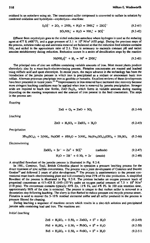
of the boundaries used. For equilibria involving a dissolved metal ion or metal ion complex in equilibriumwith its oxides, the concentration in solution must be specified. Pourbaix arbitrarily established 10"6 asthe maximum activity for the dissolved species for regions of passivation or protection due to the formationof surface films. If dissolution is desired, for example, in the hydrometallurgical extraction of metal values,10"3 is a more realistic value. Regions between these two values would represent conditions resulting incorrosion, that is, concentrations that would result in excessive metal corrosion but insufficient for effectiveextraction by dissolution. Figure 9.3-4 is a potential-pH diagram for the Cu-O-H2O system showing regionsof passivation and dissolution. The log activity values for the soluble species are indicated on the boundaries.Pourbaix1 has presented detailed diagrams for most of the metal-oxygen systems of importance in deter-mining conditions leading to corrosion and the buildup of surface films resulting in passivation.
Figure 9.3-5 is a Pourbaix, predominant-area, diagram for the S-O-H2O system for a total activity ofall dissolved sulfur species of 10" ! (ES = 10"1). The only stable sulfur species are HSO4", SOa", H2S,HS~, and elemental sulfur. The formation of elemental sulfur films occurs in acid solutions as indicated.In basic solution, during the oxidation of sulfur-bearing compounds, intermediate metastable sulfur speciessuch as thiosulfate, dithionate, and polythionates form. This is a problem previously described in the SherrittGordon process. Under acid conditions, during the dissolution of sulfide minerals, elemental sulfur layersoften form but metastable sulfur intermediates such as thiosulfate and sulfite are not observed.
Stability relationships and the sequence of formation of surface reaction layers can be predicted frompotential-pH diagrams. The Cu-O-S-H2O system will be used as an example. Figure 9.3-6 represents theCu-O-S-H2O system at ES = 10"'. Stable regions for Cu2S and CuS indicate that sulfur films will notform adjacent to Cu2S since the reaction
Cu2S = CuS + Cu2+ + 2e~ (9.3-32)
occurs with the formation of surface layers of CuS on the Cu2S substrate. If the oxidant is oxygen, cathodicreduction will consume hydrogen ions and oxygen at the surface according to the reaction
0.5 O2 + 2H+ + 2e~ = H2O (9.3-33)
If the cathodic couple involves ferric ions, then
2Fe3+ + 2e~ = 2Fe2+ (9.3-34)
without consumption of hydrogen ions.
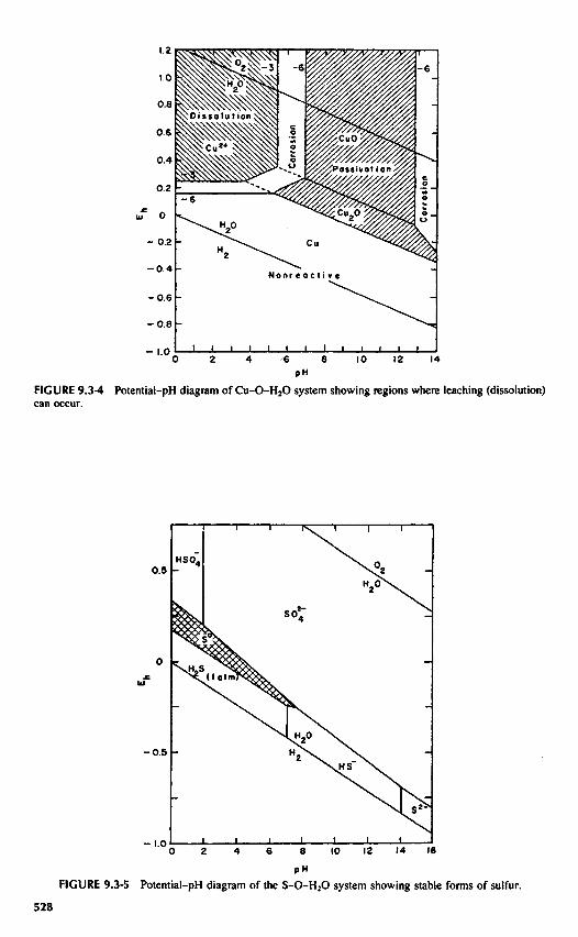
PHFIGURE 9.3-4 Potential-pH diagram of Cu-O-H2O system showing regions where leaching (dissolution)can occur.
Nonre octi ve
Dissolution
Possivot ionCorro
sion
Corr
osio
n
FIGURE 9.3-5 Potential-pH diagram of the S-O-H2O system showing stable forms of sulfur.

FIGURE 9.3-6 Potential-pH diagram of the Cu-O-S-H2O system showing regions where leaching (dis-solution) can occur.
If the kinetics are rapid enough, as experienced at high oxidation concentration and high temperature,surface polarization may occur sufficient to cause both CuS and sulfur to form. Sulfur formation occurs bythe reaction
CuS = Cu2+ + S0 + le~ (9.3-35)
resulting in the formation of surface layers of S0 on the CuS.
9.4 KINETICSOFLEACHING
9.4-1 Electrochemical Processes
Most metal sulfides and certain metal oxides are electronic conductors and are capable of establishingcorrosion and galvanic couples in aqueous solutions. Similarly, metals react by well-established kineticpatterns involving corrosion couples displaying charge transfer or diffusion overvoltages or combinationsof these depending on the metal.
Metal sulfides and several important oxides display /i-type or p-type semiconducting or metallic prop-erties. As a result of their electronic conductivity, certain minerals can participate in coupled charge transferprocesses analogous to a metal corroding in an electrolye, and the kinetics of leaching can be related tothe potential of the solid in contact with the aqueous electrolyte.
Electrochemical processes are unique in that the solid assumes a uniform potential throughout, providingohmic resistance is negligible. Consequently, the chemical reaction may be influenced over relatively longdistances. The potential may directly affect the kinetics of the reaction and may also serve to stabilizeintermediate solid phases. Concepts developed in the field of corrosion are transferable to electron-con-ducting solids in hydrometallurgical systems. The mineral particle behaves as an internally short-circuited(no external applied voltage) system where the solid assumes a mixed potential determined by associatedanodic and cathodic processes. At the mixed potential, the sum of all anodic currents, £/„, is such that
TiI11 = - S / , . or EinA = - S / , / 1 (9.4-1)
where A is the electrode area and ia and i€. are the anodic and cathodic current densities. As in corrosionprocesses, two types of mixed-potential regimes may be operative: corrosion and galvanic couples. Thecorrosion type involves a single phase having both anodic and cathodic reactions on a single mineral
Dissolution
Corro
sion
Possivotion
Cor
rosi
on

surface. A galvanic couple is operative where two or more solid phases are in electrical contact. In thisunion, each solid assumes either anodic or cathodic behavior and has its own surface area for reaction. Ifa metal sulfide, MS, is placed in contact with a solution containing an oxidant N"+ (e.g., Fe3+ in acidsolutions) having a more positive equilibrium potential, a corrosion cell will result in the anodic oxidationof MS and the cathodic reduction of Nrt+.
The half-cell reactions are
MS = Mw+ + S0 + me- (9.4-2)
N"+ + e = N ( / ' - | ) + (9.4-3)
The mineral particle is essentially a short-circuited electrochemical cell that assumes a mixed potentialbetween the half-cell potentials of reactions [Eqs. (9.4-2) and (9.4-3)]. The mixed potential depends onthe properties of the electrode surface. Potentials more positive than the equilibrium potential drive thehalf-cell reaction in the net anodic direction and potentials more negative than the equilibrium potentialdrive the reactions in the net cathodic direction.
The net current density (0 for the system is the sum of the partial current densities ia (anodic) and ir
(cathodic). The mixed potential (E) occurs where the net current density is zero; the values of the partialcurrent densities are therefore equal and of the opposite sign (/„ = — /,.).
The kinetics of electrochemical processes involve anodic and cathodic reactions influenced by voltagebiases controlled by mixed potential generated during leaching. Recently, Hiskey and Wads worth1 reviewedmethods for evaluating mixed potentials and the net effect on anodic and cathodic mineral rate processes.Such details are beyond the scope of this discussion but do explain two important kinetic observations inthe leaching of electron-conducting phases: (1) the often-observed fractional reaction orders and (2) theformation of solid phases in sequence. The kinetic processes included here are those observed to be operativeduring the leaching of ore fragments where diffusional mass transfer of lixiviants is rate controlling. Whileelectrochemical processes may be involved at reaction interfaces, mass transfer predominates and is thebasis for engineering simulation and design.
9.4-2 Leaching of Matrix Ore Mineral
The treatment presented here relates to the leaching kinetics of an ore fragment with its array of minerals.For purposes of clarity, the ore fragment is referred to as a matrix block. In this section the treatmentincludes primarily the kinetics of single matrix-block reactions exclusive of bulk flow parameters.
Virtually all researchers agree that the leaching of ore fragments involves penetration of solution intothe rock pore structure. The kinetics thus involve diffusion of lixiviant into the rock where reaction withindividual mineral particles occurs. The kinetics are complicated by changing porosity, pH, and solutionconcentration. Bartlett2 applied the continuity equation to a system in which a copper porphyry ore, con-taining chalcopyrite as the major copper sulfide mineral, is subjected to oxidation under conditions proposedby researchers at the Lawrence Livermore Laboratory (LLL) for deep solution mining.3 Diffusion of oxygenand subsequent reaction with mineral particles combine to give a non-steady-state concentration gradientwithin the ore fragment. This treatment provides a basis for modeling of all similar leaching systems. Theshrinking-core concept used by several researchers is a special case of this general treatment. Figure 9.4-1 illustrates the mineral fragment, showing different regions at some time /. Oxygen and copper gradientsvary markedly over a broad zone in which chalcopyrite (Cp) particles extend from partly to totally reacted.The fragment, considered as spherical, may be viewed in cross section, as divided into annular rings ofthickness Ar. IfJ is the net total flux of dissolved reactant diffusing into and out of this incremental volume,the continuity equation for an individual ore fragment is
(9.4-4)
where e is porosity, C is concentration, t is time, A is the area at radius r, and (R is the rate of loss ofreactant per unit volume because of reaction with mineral particles. Actually, this is a summation of rateprocesses for all mineral types and sizes, within the incremental volume. The porosity € must be includedsince only the solution volume is involved. Combining Eq. (9.4-4) with Fick's diffusion equations gives
(9.4-5)
where Dcff is the effective diffusivity. The effective diffusivity is related to the intrinsic diffusivity, D, bythe equation
(9.4-6)

FIGURE 9.4-1 Schematic drawing illustrating the leaching of a matrix mineral fragment containing dis-seminated copper su I fide particles.
where T is the tortuosity. The operator V2 depends on the geometry of the ore particles and is defined bythe following equation for the case of spherical ore fragments:
(9.4-7)
Normally, spherical fragment geometry may be used, although nonspherical geometry may be required formatrix blocks from layered deposits. For spheres, Eq. (9.4-4) becomes
(9.4-8)
AN steady-state approximation of the continuity equation can be applied if the consumption rate oflixiviant, E(Rx, is much greater than the accumulation term, 6 BC/dt.A
The assumption of steady state reduces the complex partial differential equation to a simpler ordinarydifferential expression of the continuity equation for the k mineral types present:
(9.4-9)
Braithewaite5 and Madsen and Wadsworth6 used the simplified continuity equation for copper sulfideores using finite difference approximations. The spherical ore matrix was divided into j concentric shellsof thickness Ar, withy = 1 corresponding to the center and J = n to the outer edge of the spherical matrixparticle. The term (R may be evaluated using the equation
(9.4-10)
The term Lk(Rjk is the rate of consumption of lixiviant at position./ for all k minerals in the fragment.Equation (9.4-9) satisfactorily correlated experimental results for various ore types and matrix-block sizedistributions.
If the rate of reaction of individual mineral particles is fast enough, the region of partially leached
PARTIALLYLEACHED Cp
UNLEACHEO Cp
[ROCK]
OXYG
EN CON
CENT
RATI
ON
COPPER CON
TENT
OF ROCK
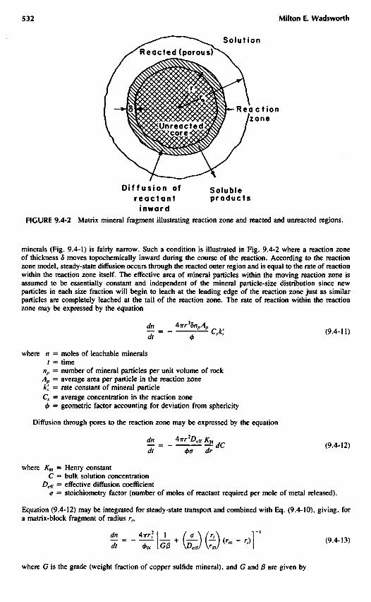
Diffusion of Solublereactant products
inwordFIGURE 9.4-2 Matrix mineral fragment illustrating reaction zone and reacted and unreacted regions.
minerals (Fig. 9.4-1) is fairly narrow. Such a condition is illustrated in Fig. 9.4-2 where a reaction zoneof thickness 8 moves topochemically inward during the course of the reaction. According to the reactionzone model, steady-state diffusion occurs through the reacted outer region and is equal to the rate of reactionwithin the reaction zone itself. The effective area of mineral particles within the moving reaction zone isassumed to be essentially constant and independent of the mineral particle-size distribution since newparticles in each size fraction will begin to leach at the leading edge of the reaction zone just as similarparticles are completely leached at the tail of the reaction zone. The rate of reaction within the reactionzone may be expressed by the equation
(9.4-11)
where n = moles of leachable minerals/ = time
np = number of mineral particles per unit volume of rockAp = average area per particle in the reaction zonek's = rate constant of mineral particleCx — average concentration in the reaction zone4> = geometric factor accounting for deviation from sphericity
Diffusion through pores to the reaction zone may be expressed by the equation
(9.4-12)
where Ku = Henry constant
C — bulk solution concentration£>cfl ss effective diffusion coefficient
a = stoichiometry factor (number of moles of reactant required per mole of metal released).
Equation (9.4-12) may be integrated for steady-state transport and combined with Eq. (9.4-10), giving, fora matrix-block fragment of radius rh
where G is the grade (weight fraction of copper sulfide mineral), and G and 0 are given by
Unreactedcore
R e a c t i o n/zone
R e a c t e d (porous)
Solut ion

where rp = average mineral particle radiuspp = mineral particle densitypr = bulk rock density
Equation (9.4-13) may be integrated numerically and summed over all matrix-block sizes. Braun et al.3
applied this model to a 5.8 x 10⁶ g sample of primary copper ore with matrix-block sizes between 0.01and 16 cm. The effect of weathering was accounted for by a systematic correction of the sphericity factor,
Madsen et al. applied the reaction zone model to the leaching of Butte ore for particles up to 6 in. indiameter. Columns 5 ft in diameter, containing 5 tons of ore, were used. The principal copper mineral wasCu2S. Equation (9.4-13) in integrated form was used:
(9.4-14)
where a, is the fraction reacted for the ith particle size. Also
and
where MW is the molecular weight of the copper sulfide mineral.Researchers in general agree that ore matrix-block rate processes in copper dump leaching involve mass
transfer of Fe(III) species by diffusion through pores, cracks, and fissures. Ferric ion in solution [Fe(III)]exists in several forms. Thermodynamically, the more important forms are Fe(SO4J2", FeSO4*,Fe2(OH)2
+, FeHSOj+, and FeOH2+. As noted earlier, the sulfate complexes are favored over the hydroxylcomplexes. Figure 9.4-3 illustrates an ore fragment showing the pore structure and diffusion of ions. Asurface film, depicted flowing over the cross section on the right, is exposed under optimum conditions toconvective air flow. Oxygen transfer to the liquid film occurs by diffusion. In well-aerated dumps, transferof oxygen to the liquid phase is not rate limiting because of the large surface areas involved. Ferrous ionin the film is oxidized to the ferric state, a reaction requiring bacterial oxidation to occur at a rate suitablefor leaching to proceed. The Fe(III) complex species produced by bacterial oxidation diffuse through thepore structure, reacting with sulfide minerals and releasing cuprous and ferrous ions, which, in turn, mustdiffuse in directions indicated by the localized concentration gradients. Copper may diffuse to the centerof the ore fragment and continue to diffuse if a gradient is established by secondary enrichment reactions.Release of copper and ferrous iron occurs by outward diffusion through the pore structure of the rockfragment joining the flowing film. During rest cycles, leaching continues with a buildup of dissolved metalvalues in the immobile aqueous phase held by capillary forces. When the rock fragment is first exposed tosolution, surface reaction control may occur, followed by increased kinetic dependence on diffusion as theprocess continues. The rate of extraction may thus be the sum of surface convective transfer, surfacechemical reaction, and diffusion through the pore structure.
Roman et al.8 developed a model for the leaching of copper oxide ores using the shrinking-core model.They found that the surface reaction is fast so that only the diffusion term need be considered. Theconsumption of acid, A, is related to the copper recovery by the expression
(9.4-15)
where a = (weight of acid)/(weight of Cu) consumed in the reaction. The value of a may be determinedexperimentally. The diffusion equation becomes accordingly
(9.4-16)
where ay refers to the fraction recovered from the ith particle size in volume increment j , G is the grade.

FIGURE 9.4-3 Matrix mineral fragment showing pore network and diffusion paths for solubilized metalions.
pr is the ore density, 0 is a geometry factor, and Z>eff is the effective diffusivity. Equation (9.4-16) may beevaluated numerically and summed over all unit volumes in the flow path. Within one incremental volume,
where a>, is the weight fraction of particle size i. Summing over all values of j gives the total fractionrecovered:
In addition to these studies, Cathles and Apps9 modeled a dump-leaching system including flow, airconvection, and heat flow. This analysis was a field study of the Midas Dump at Bingham Canyon, Utah,and contributed significantly to dump-leach modeling in general. Recently, Gao et al.IOM developed adetailed model for solution mining of rubblized ore in situ including flow and ore fragment kinetics forsingle- and two-phase flow.
9.4-3 Aqueous Phase Oxidation-Reduction Processes
The aqueous solutions of importance to leaching technology for most conditions must provide suitablepotential-pH conditions to promote oxidative dissolution of metals and metal sulfides. To provide thiscapability, solutions must contain a lixiviant that can be reduced. Conceptually, the lixiviant half-cellpotential must be above that of the corresponding metal or metal sulfide zero-current potential. The greaterthis difference in voltage the greater the driving force. The important lixiviants to be considered are Fe(II)/Fe(III), oxygen, and hydrogen peroxide. These reactions are not all inclusive but simply represent importantreactants currently used in leaching.
Ferric-ion complexes are important in acid-sulfate leaching because ferric ion can be generated fromferrous ion using air or oxygen in situ. The reduction of ferric iron to ferrous occurs as the ferric-ioncomplex diffuses through fluid-filled pores and channels in the rock matrix and encounters reactive metalsor sulfides. In most instances, as already discussed, the rate of ferric ion reduction is a diffusion-limitedprocess. The oxidation of ferrous iron to ferric in aqueous solution becomes of primary importance becauseof its in situ regeneration capacity under appropriate oxidation potentials.
Burkin12 has reviewed some of the reaction mechanisms expected to be important in solution extractionsystems. The rate of oxidation of ferrous ion in acid sulfate, nitrate, and perchlorate solutions follows therate expression at low temperature and, in the absence of cupric ions,13
(9.4-17)
fM TEHfOH OF OHE FHAfAfEMT^
SOLUTfOM
AlHPOHE NETWOtX
SURFACE OF OHEFHAfMEMT
BACTEHfA
POHOUS tHOM SALTSfPHECfPf TATE DUHfMC
LEACHIMC)

The reaction is third order overall with first-order dependence on oxygen and second-order dependence onferrous ion. These authors and others14 have noted the catalytic effect of cupric ions on the kinetics offerrous ion oxidation, explained by the reaction
- ~ T " ^ = k*po№2+)2 + ^ 2[Fe 2 +][Cu 2 +] (9.4-18)at
McKay and Halpern15 developed a somewhat different rate expression for the catalytic contribution, havingthe form
- ^LH = -*;/> o ,[Fe 2 + ] 2 + * ; [ F e 2 + ] 2 I C u 2 + ] 0 5 (9.4-19)at
At 30.50C the values for the constants in Eq. (9.4-18) are k\ = 1.5 X 10~5 L/m • atm • s and Jt2 = 7 - 6
x 10"3 L/m • s. For small concentrations of Cu 2 + (e.g., 0.1 g/L) the second term of Eq. (9.4-18) ismuch larger than the first. The second term of Eq. (9.4-19) includes an oxygen pressure term, which seemsto be in accord with observed results in dump leaching where little oxidation occurs in the absence ofautotrophic bacteria for the retention time observed for large dumps.
Brierley16 reviewed research on the biogenic oxidation of iron and cited the work of Lacey and Lawson17
which indicates that the biogenic oxidation rate is 500,000 times faster than the nonbiogenic oxidation rate.Autotrophic bacteria are thus essential for effective leaching at low oxygen potentials where the activity ofoxygen is much lower than that of Fe 3 + generated biogenically. The rate of biogenic oxidation was proposedto follow the expression
-<f[Fe2+] Mm[Fe^]X
dt -Y(K + IFJ+]) ( 9 - 4 " * 0
where [Fe2 +] is in g/L, fim is the maximum specific growth rate of bacteria per hour, Y is the mass ofbacteria produced per gram of Fe 2 + oxidized, K is the saturation constant in g/L F e 2 + , and X is theconcentration of bacteria (g/L).
Oxygen is an essential intermediate in ferrous iron oxidation. In solution mining systems at elevatedpressure, oxygen may become the dominant oxidizing lixiviant in the system. Diffusion of oxygen wouldthus be rate controlling in matrix-block kinetics. The solubility of oxygen in water-air equilibrium at 30°is 2.28 X 10"4 mol/L. In dump leaching, typically [Fe3 +] = 10"2 mol/L. Leaching systems using pureoxygen under hydrostatic pressure would accommodate greater solubilities of oxygen. For example, pureoxygen under 300 ft of hydrostatic head would have a solution activity approximately 10~2 mol/L F e 3 + .For greater depths the relative contribution of oxygen would increase.
Oxygen reduction occurs through the formation of peroxide intermediates. Vetter18 has reviewed oxygenredox reactions at metal electrode surfaces. On platinum the current for cathodic reduction is
«'--*1OJ«P(-^) (9-4"2 I>
and for acid and neutral solutions
i = -*'[OJ[H+] exp ( - H ) (9.4-22)
The rate of hydrogen peroxide reduction is important both as a lixiviant and as an intermediate inoxygen reduction. The rate of H2O2 reduction is given by the equation18
'--''WTTK^i-TKrI (94-23)
where K is the dissociation constant for H2O2 and CH3O2
= [H2O2] + [HO2~]. The use of hydrogen peroxideas an oxidant is limited by its rapid anodic decomposition
H2O2 = O2 + 2H + + 2e~ (9.4-24)
The decomposition is catalyzed by ferrous ion and metallic surfaces. Even in alkaline solutions, such as
used in carbonate uranium solution mining, iron present as colloidal ferric oxides (hydroxides) catalyze thedecomposition. The half-life of H2O2 is approximately 30 min under alkaline solution mining conditions.
NOTATION
activity and activity of /th componentareaconcentrationintrinsic diffusivityeffective difrusivitypotentialhalf-cell and standard half-cell potentials, respectively
Faraday numberstandard Gibbs free energy of reactioncurrentanodic and cathodic current densities, respectivelynet total flux of dissolved reactantrate constantHenry constantmolecular weightpressurepartial pressures of oxygen and hydrogen, respectivelyideal gas constantrate of loss of reactant per unit volumeradiustimetemperature
Greek Letters
porositystoichiometry coefficientchemical potentialdensitytortuosity
REFERENCES
Section 9.1
9.1-1 R. H. Lamborn, The Metallurgy of Copper, p. 180, Lockwood and Company, London, 1875.9.1-2 F. Bushnell, "Precipitating of Copper from Mine Waters," in T. Read (Ed.), Mining and Scientific
Press, Nov. 1914, editorial comment by W. G. Nash, pp. 329-330.9.1-3 H. Kondo, Lives in Science, Part 4, II, pp. 127-140, Simon and Schuster, New York, 1957.9.1-4 W. H. Dennis, A Hundred Years of Metallurgy, p. 141, Aldine Publishing, Chicago, 1964.9.1-5 Fathi Habashi, Principles of Extractive Metallurgy, Vol. 2, Gordon and Breach, New York, 1970.9.1-6 David J. I. Evans, Production of Metals by Gaseous Reduction from Solution—Processes and
Chemistry, in Advances in Extractive Metallurgy, pp. 831-907, The Institute of Mining andMetallurgy, London, 1968.
9.1-7 R. Deny, Pressure Hydrometallurgy: A Review, Min. ScL Eng., 4, 2-24 (1972).9.1-8 Fathi Habashi, Pressure Hydrometallurgy: Key to Better and Non-polluting Process, Eng. Min.
J., 88-94 (May 1977).9.1-9 F. Habashi, Karl Josef Bayer (1847-1904), in F. Habashi (Ed.), Progress in Extractive Metallurgy,
Vol. 1, pp. 1-16, Gordon and Breach, New York, 1973.

9.1-10 W. H. Dennis, A Hundred Years of Metallurgy, pp. 234-239, Aldine Publishing, Chicago, 1964.9.1-11 G. M. Ritcey and A. W. Ashbrook, Solvent Extraction Principles and Applications to Process
Metallurgy, Part II, Elsevier, New York, 1979.9.1-12 K. L. Power, Operation of the First Commercial Copper Liquid Ion Exchange and Electrowinning
Plant, in R. P. Ehrlich (Ed.), Copper Metallurgy, pp. 1-26, TMS-SME-AIME Symposium,Denver, CO, February 15-19, 1970.
9.1-13 V. Arregui, A. R. Gordon, and G. Steinveit, The Jarosite Process—Past, Present and Future, inJ. M. Cigan, T. S. Mackey, and T. J. O'Keefe (Eds.), Lead-Zinc-Tin '80, pp. 97-123, TheMetallurgical Society of AIME, Warrendale, PA, 1979.
9.1-14 M. E. Wadsworth and C. H. Pitt, "An Assessment of Energy Requirements in Proven and NewCopper Processes," December 1980, DOE/CS/40132.
9.1-15 H. H. Kellogg, The State of Nonferrous Metallurgy, J. of Metals, 30, 35-42 (1982).9.1-16 R. R. Dorfler and J. M. Laferty, Review of Molybdenum Recovery Processes, in H. Y. Sohn,
O. N. Carlson, and J. T. Smith (Eds.), Extractive Metallurgy of Refractory Metals, pp. 1-17;TMS-AIME, Warrendale, PA, 1980.
9.1-17 M. Shamsuddin and H. Y. Sohn, Extractive Metallurgy of Tungsten, in H. Y. Sohn, O. N.Carlson, and J. T. Smith (Eds.), Extractive Metallurgy of Refractory Metals, pp. 205-230; TMS-AIME, Warrendale, PA, 1980.
9.1-18 J. R. Boldt, Jr. and P. Queneau, The Winning of Nickel, p. 348, Longmans Canada, Ltd., Toronto,1967.
Section 9.2
9.2-1 W. J. Schlitt, Current Status of Copper Leaching and Recovery in the U.S. Copper Industry, inLeaching and Recovering Copper, Chap. 1, SME-AIME Symposium, Las Vegas, Nevada, Feb-ruary 1979.
9.2-2 D. L. Whiting, "Groundwater Hydrology of Dump Leaching and In Situ Solution Mining,"Mackay School of Mines, Groundwater Hydrology and Mining Short Course, University of Ne-vada, Reno, Nevada, October 15, 1976.
9.2-3 J. S. Jackson and B. P. Ream, Solution Management in Dump Leaching, in Leaching and Re-covering Copper, Chap. 7, SME-AIME Symposium, Las Vegas, Nevada, February 1979.
9.2-4 R. L. S. Willis, Ferrous-Ferric Redox Reaction in the Presence of Sulfate Ion, Trans. FaradaySoc.,S% 1315(1963).
9.2-5 H. J. Heinen, G. E. McClelland, and R. E. Lindstrom, Enhancing Percolation Rates in HeapLeaching of Gold-Silver Ores, U.S. Bur. Mines Rep. Invest., 8388, 1979.
9.2-6 G. E. McClelland and J. A. Eisele, Improvements in Heap Leaching to Recover Silver and Goldfrom Low-Grade Resources, U.S. Bur. Mines Rep. Invest., 8612, 1982.
9.2-7 H. J. Heinen, D. G. Peterson, and R. E. Lindstrom, Processing Gold Ores Using Heap Leach-Carbon Adsorption Methods," U.S. Bur. Mines Inf. Circ, 8770, 1979.
9.2-8 G. J. McDougall, R. D. Hancock, M. J. Nichol, O. L. Wellington, and E. F. Copperthwaite,The Mechanism of the Adsorption of Gold Cyanide on Activated Carbon, J. S. Afr. Inst. Min.Metall., 80, 344-356 (1980).
9.2-9 L. White, Heap Leaching Will Produce 85000 oz/year of Dore Bullion for Smoky Valley MiningCo., Eng. Min. J., 178, 70-72 (1977).
9.2-10 R. Pizarro, J. D. McBeth, and G. M. Potter, Heap Leaching Practice at the Carlin Gold MiningCo., in F. F. Apian, W. A. McKinney, and A. D. Pernichele (Eds.), Solution Mining Symposium,SME and TMS-AIME, New York, 1974.
9.2-11 F. W. McQuiston, Jr. and R. S. Shoemaker, Gold and Silver Cyanidation Plant Practice, Mono-graph SME-AIME, Vol. I (1975), Vol. II (1981), Denver, CO.
9.2-12 G. M. Potter and H. P. Salisbury, Innovations in Gold Metallurgy, Min. Congr. J., 60, 54-57(1974).
9.2-13 G. Wargalla and W. Brandt, Processing of Diaspora Bauxites, in G. M. Bell (Ed.), Light Metals1981, pp. 83-100, TMS-AIME, Warrendale, PA, 1981.
9.2-14 V. G. Hill and R. J. Robson, The Classification of Bauxites from the Bayer Plant Standpoint, inG. M. Bell (Ed.), Light Metals 1981, pp. 15-27, TMS-AIME, Warrendale, PA, 1981.
9.2-15 M. H. Caron, "Treating Nickel and Cobalt Ores," U.S. Patent 1487145 (1924).9.2-16 J. R. Boldt, Jr. and P. Queneau (Eds.), The Winning of Nickel, p. 425, Longmans Canada, Ltd.,
Toronto, 1967.

9.2-17 L. F. Power and G. H. Geiger, The Application of the Reduction Roast-Ammoniacal AmmoniumCarbonate Leach to Nickel Laterites, Min. ScL Eng., 9, 32-51 (1977).
9.2-18 N. Calvin and J. W. Gulyas, The Marinduque Surigao Nickel Refinery, in D. J. I. Evans, R. S.Shoemaker, and H. Veltman (Eds.), International Laterite Symposium, pp. 346-356, SME-AIME,New York, 1979.
9.2-19 W. P. C. Duyvesteyn, G. R. Wicker, and R. E. Doane, An Omniverous Process for LateriteDeposits, in D. J. I. Evans, R. S. Shoemaker, and H. Veltman (Eds.), International LateriteSymposium, pp. 553-570, SME-AIME, New York, 1979.
9.2-20 R. C. Merritt, The Extractive Metallurgy of Uranium, Colorado School of Mines Research Insti-tute, Golden, CO, 1977.
9.2-21 E. G. Parker, D. R. McKay, and H. Salomon-de-Freidberg, Zinc Pressure Leaching at Cominco'sTrail Operation, in K. Osseo-Asare and J. D. Miller (Eds.), Hydrometallurgy—Research, Devel-opment and Practice, pp. 927-940, TMS-AIME, Warrendale, PA, 1982.
9.2-22 J. R. Boldt, Jr. and P. Queneau (Eds.), The Winning of Nickel, pp. 299-314, Longmans Canada,Ltd., Toronto, 1967.
9.2-23 A. R. Gordon and R. W. Pickering, Improved Leaching Technologies in the Electrolytic ZincIndustry, Met. Trans. B., 6B, 43 (1975).
9.2-24 V. Arregui, A. R. Gordon, and G. Steintveit, The Jarosite Process—Past, Present and Future, inJ. M. Cigan, T. S. Mackey, and T. J. O'Keefe (Eds.), Lead-Zinc-Tin W, pp. 97-123, TMS-AIME, Warrcndale, PA, 1979.
9.2-25 V. Arregui, A. R. Gordon, and G. Steinveit, Pilot Plant Demonstration of Zinc Sulfide PressureLeaching, in J. M. Cigan, T. S. Mackey and T. J. O'Keefe (Eds.), Lead-Zinc-Tin W, pp. 407-425, TMS-AIME, Warrendale, PA, 1979.
9.2-26 E. G. Parker, D. R. McKay, and H. Solomon-de-Friedberg, Zinc Pressure Leaching at Cominco'sTrail Operation, in K. Osseo-Asare and J. D. Miller (Eds.), Hydrometallurgy—Research, Devel-opment and Plant Practice, pp. 927-940, TMS-AIME, Warrendale, PA, 1982.
9.2-27 D. A. Shock and F. R. Conley, Solution Mining—Its Promise and its Problems, in F. F. Apian,W. A. McKinney, and A. D. Pernichele (Eds.), Solution Mining Symposium, pp. 79-97, SME-TMS-AIME, New York, 1974.
Section 9.3
9.3-1 M. Pourbaix, Atlas of Electrochemical Equilibria in Solutions, Pergamon Press, New York, 1966.9.3-2 H. A. Pray, C. E. Schweickert, and B. N. Minnich, Ind. Eng. Chem., 44, 1146 (1952).9.3-3 R. M. Garrels and C. L. Christ, Solutions, Minerals, and Equilibria, Harper & Row, New York,
1965.
Section 9.4
9.4-1 J. B. Hiskey and M. E. Wadsworth, Electrochemical Processes in the Leaching of Metal Sulfidesand Oxides, in M. C. Kuhn (Ed.), Process and Fundamental Considerations of Selected Hydro-metallurgical Systems, pp. 303-325, SME-AIME, New York, 1981.
9.4-2 R. W. Bartlett, Pore Diffusion—Limited Metallurgical Extraction from Ground Ore Particles, Met.Trans., 3 , pp. 913-977 (1972).
9.4-3 R. L. Braun, A. E. Lewis, and M. E. Wadsworth, In-Place Leaching of Primary Sulfide Ores:Laboratory Leaching Data and Kinetics Model, Met. Trans., 5, 1717-1726 (1974).
9.4-4 H. Y. Sohn and J. Szekely, A Structural Model for Gas-Solid Reactions with a Moving Boundary—Part III, Chem. Eng. ScL, 27, 763-778 (1972).
9.4-5 J. W. Braithewaite, "Simulated Deep Solution Mining of Chalcopyrite and Chalcocite," Ph.D.Dissertation, Deptartment of Metallurgical Engineering, University of Utah, 1976.
9.4-6 B. W. Madsen and M. E. Wadsworth, A Mixed Kinetics Dump Leaching Model for Ores Con-taining a Variety of Copper Sulfide Minerals, U.S. Bur. Min. Rep. Invest., 8547, 1981.
9.4-7 B. W. Madsen, M. E. Wadsworth, and R. D. Groves, Application of a Mixed Kinetics Model tothe Leaching of Low Grade Copper Ores, Trans. Soc. Min. Eng., 258, 69-74 (1974).
9.4-8 R. J. Roman, B. R. Benner, and G. W. Becker, Diffusion Model for Heap Leaching and ItsApplication to Scale-Up, Trans. Soc. Min. Eng., 256, 247-256 (1974).
9.4-9 L. M. Cathles and J. A. Apps, A Model of the Dump Leaching Process that Incorporates OxygenBalance, Heat Balance and Air Conductivity, Met. Trans. B, 6B, 617-624 (1975).
9.4-10 H. W. Gao, H. Y. Sohn, and M. E. Wadsworth, A Mathematical Model for the Solution Mining

of Primary Copper Ore: Part I. Leaching by Oxygen-Saturated Solution Containing No Gas Bub-bles, Met. Trans. B, 14B, 541-551 (1983).
9.4-11 H. W. Gao, H. Y. Sohn, and M. E. Wadsworth, A Mathematical Model for the Solution Miningof Primary Copper Ore: Part II. Leaching by Solution Containing Oxygen Bubbles, Met. Trans.B, 14B, 553-558 (1983).
9.4-12 A. R. Burkin, The Chemistry of Hydrometallurgical Processes, Van Nostrand, Princeton, NJ,1966.
9.4-13 R. E. Huffman and N. Davidson, Kinetics of the Ferrous Iron-Oxygen Reaction in Sulfuric AcidSolution, J. Am. Chem. Soc, 78, 4836 (1956).
9.4-14 P. George, The Oxidation of Ferrous Perchlorate by Molecular Oxygen, J. Chem. Soc. {London),
280,4836(1954).
9.4-15 D. R. McKay and J. Halpem, A Kinetic Study of the Oxidation of Pyrite in Aqueous Suspension,Trans. AIME, 212, 301-308 (1958).
9.4-16 C. L. Brieriey, Bacterial Leaching, Crit. Rev. Microbiol., 6, 207-262 (1978).9.4-17 D. T. Lacey and F. Lawson, Kinetics of the Liquid Phase Oxidation of Acid Ferrous Sulfate by
the Bacterium Thiobacillus thiooxidans, Biotech. Bioeng., 12, 29-50 (1970).9.4-18 K. J. Vetter, Electrochemical Kinetics, Academic Press, New York, 1967.