Embed Size (px)
Citation preview
minerals
Article
Leaching of Ca-Rich Slags Produced from Reductive Smeltingof Bauxite Residue with Na2CO3 Solutions for AluminaExtraction: Lab and Pilot Scale Experiments
Michail Vafeias 1,* , Amalia Bempelou 1, Eirini Georgala 1, Panagiotis Davris 2, Efthymios Balomenos 2
and Dimitrios Panias 1
�����������������
Citation: Vafeias, M.; Bempelou, A.;
Georgala, E.; Davris, P.;
Balomenos, E.; Panias, D. Leaching of
Ca-Rich Slags Produced from
Reductive Smelting of Bauxite
Residue with Na2CO3 Solutions for
Alumina Extraction: Lab and Pilot
Scale Experiments. Minerals 2021, 11,
896. https://doi.org/10.3390/
min11080896
Academic Editor: Jean-François Blais
Received: 15 June 2021
Accepted: 13 August 2021
Published: 19 August 2021
Publisher’s Note: MDPI stays neutral
with regard to jurisdictional claims in
published maps and institutional affil-
iations.
Copyright: © 2021 by the authors.
Licensee MDPI, Basel, Switzerland.
This article is an open access article
distributed under the terms and
conditions of the Creative Commons
Attribution (CC BY) license (https://
creativecommons.org/licenses/by/
4.0/).
1 School of Mining and Metallurgical Engineering, National Technical University of Athens,15780 Athens, Greece; [email protected] (A.B.); [email protected] (E.G.);[email protected] (D.P.)
2 MYTILINEOS S.A., Metallurgy Business Unit, Ag. Nikolaos, 32100 Viotia, Greece;[email protected] (P.D.); [email protected] (E.B.)
* Correspondence: [email protected]; Tel.: +30-210-772-2299
Abstract: Sustainable utilization of Bauxite Residue (BR) is currently one of the greatest challengesbeing tackled by the alumina industry, due to its high production rates and limited reuse options.The present work is concerned with the use of BR as a candidate metallurgical raw material foriron (Fe) production and aluminum (Al) extraction. In more detail, at first, BR undergoes reductivesmelting to extract its Fe content and produce a slag of mainly calcium aluminate composition. Ina second step, Al contained in the calcium aluminate phases is extracted hydrometallurgically byleaching with a Na2CO3 aqueous solution. The focus of the current study is the optimization of thisleaching process, and it was performed in two stages. The first was a laboratory scale investigationon the main parameters affecting the extraction rate of Al. The second stage was performed in pilotscale and incorporated observations and suggestions based on the laboratory scale investigation.Laboratory work showed that more than 50% of aluminum could be easily extracted in less than 1 h,in 5% S/L, at 70 ◦C and with an 20% excess of Na2CO3. Pilot scale work, by successfully applying thesuggestions derived from laboratory scale work, achieved an average Al extraction of 68% from a 10%S/L pulp, with a slag of optimized composition in relation to the one used in the laboratory scale.
Keywords: bauxite residue; red mud; slag valorization; alumina; leaching; zero-waste;calcium aluminates
1. Introduction
Bauxite Residue (BR) is the term used to describe the solid residue produced fromthe alkaline digestion of bauxite in the Bayer Process for the production of aluminumoxide (alumina, Al2O3). BR is produced in large amounts in alumina refineries: about0.9–1.5 tons of BR per ton of Al2O3, depending on bauxite quality and plant operatingconditions. This by-product is currently one of the greatest sustainability challenges facedby the alumina industry [1]. Storage of the wet or dry residue in disposal sites is not aviable option in the long term, especially when one considers the global stock of BR, whichwas estimated at 2.7 billion tons in the beginning of the previous decade [2]. Given the lackof large-scale BR reuse options [3], this amount is expanding with increasing rates, due tothe raise in demand of primary aluminum. Global production of alumina was estimated at134 million metric tons for 2020, the majority of which was produced by Bayer plants [4].On the road to sustainability and a zero-waste production process, the alumina industry isorienting its efforts on possible utilization processes for BR, among which are processes forthe extraction of metal values from BR.
The main feature of BR as a candidate metallurgical raw material is its chemical andmineralogical heterogeneity. Major metal values contained in BR are Fe, Al, Na and Ti.
Minerals 2021, 11, 896. https://doi.org/10.3390/min11080896 https://www.mdpi.com/journal/minerals

Minerals 2021, 11, 896 2 of 24
Other metals of economic interest that are commonly found in BR are Ga, V, Sc and theREEs. The latter are found in minor amounts. As the concentrations of the major metals inBR are lower compared to their respective concentrations in metallurgical grade ores usedfor their extraction, the only viable economic option for its processing is the production ofseveral metals by single integrated process [5].
The Laboratory of Metallurgy of the National Technical University of Athens (NTUA)and MYTILINEOS Aluminium of Greece plant are participating in the H2020 RemovalProject [6], a collaborative research project which evaluates different process routes for thevalorization of Greek BR. Among other alternatives, a two-stage process for the extractionof the Fe and Al content of Greek BR is studied. The main goal of the first stage of theprocess under consideration is the extraction of the Fe content of BR, in the form of metalliciron. This is achieved by a reductive smelting operation. A second goal is the productionof a slag of suitable phase composition, which will be further treated for the extraction ofAl. The second stage of the process is the alkaline extraction of Al from the slag producedin the reductive smelting step, by leaching with an aqueous Na2CO3 solution. In Figure 1,a conceptual flowsheet of the process is shown.
Figure 1. Conceptual flowsheet of the metallurgical process for the treatment of BR under investiga-tion in the present work.
Processes for the extraction of Fe usually comprise the first stage in most integratedprocess flowsheets studied for the metallurgical treatment of BR. This is logical, consideringthat Fe is the most concentrated metal value found in BR and the one causing the mostdifficulties downstream in process flowsheets that aim at the extraction of other valuablemetals. Process alternatives for the extraction of Fe from BR have been reviewed by X. Liuet al. [7]. Reductive smelting of BR is a process option that usually aims at the productionof a marketable iron alloy. D. Valeev et al. used neutralized (Na-free) BR from the UralAluminum Plant in a reductive smelting process [8]. At 1750 ◦C, they produced pig iron,low in sulfur (S) and high in Ti (~1.12 wt.%), V (~0.49 wt.%) and P(~0.96 wt.%). Reductivesmelting of Greek BR has been studied by various research groups, in relation to processflowsheets that aim at the extraction of Sc and REEs. It is estimated that Greek BR producedat the MYTILINEOS Aluminium of Greece plant contains on average ~1 kg of REEs perton of BR (dry basis) with Sc averaging ~120 g per ton (0.02% Sc2O3) [9]. C. R. Borra et al.studied a three-stage process to treat Greek BR for the extraction of Al, Fe and REEs [10].The first stage was an alkali roasting stage with Na2CO3, that aimed at the removal of Aland Na from BR. By this process, about 75% of alumina contained in BR was extracted by

Minerals 2021, 11, 896 3 of 24
water leaching, at 80 ◦C, in 1 h. The Al-depleted BR was then reductively smelted, withcarbon as the reductant, leading to a 98 wt.% extraction of Fe. REEs concentration in theleaching residue was higher by a factor of 3 and was directly leached with mineral acids.Sc extractions were over ~80% for both HCl and H2SO4 leaching of the slag residue. R.M. Rivera et al. studied a reductive smelting–HPAL process for the selective extractionof REEs [11]. The reductive smelting step aimed, firstly, at the extraction of Fe, whichposes challenges in the downstream process of acid extraction of the REEs. Secondly,different slag compositions and slag crystallinity (glassy or crystalline) were studied byusing different flux mixtures (CaO and SiO2) and cooling rates. After the reductive smeltingstep, the concentration of Fe in all slags was below ~4 wt.%. Extraction rates for the Scfrom the slags were up to 90 wt.% for HPAL with H2SO4 at 150 ◦C and up to 80 wt.%HPAL with HCl at 120 ◦C. Moreover, more than 90% wt.% of the Al contained in the slagswas recovered.
Processing of BR for the extraction of Al is studied by acid and alkaline routes, dueto the amphoteric character of Al. Processing options include, either the direct processingof BR, or processing of intermediate phases produced by prior treatment, as is the case ofslags produced after the reductive smelting of BR described earlier. The various processalternatives have been reviewed multiple times [12–14]. Relevant to the process underinvestigation is the work by B. Friedrich and F.M. Kaußen, who studied different alkalineprocess routes for the extraction of Al from homogenized BR recovered from a closedindustrial landfill [15,16]. Among the processes studied was one termed “Pedersen–BayerProcess” which consisted of a reductive smelting step for the extraction of the Fe contentof BR and subsequent pressure leaching of the slag with NaOH for the extraction ofAl. Different slag compositions were formed by gradually increasing lime additions.The authors identified that most of the phases formed were either insoluble or neededaggressive leaching conditions in all slag compositions produced. It is reported thatleaching at 250 ◦C, with 200 g/L NaOH, led to 50% Al extraction and 200 mg/L Si co-dissolution independent of slag phase composition. Aluminum recovery of 95% wasachieved from a slag with CaO/SiO2 equal to 1.4, by leaching with a solution containing465 g/L NaOH, for 2 h leaching time, at a temperature of 280 ◦C. The authors concludethat such conditions are of no practical industrial interest.
The process studied in the present work is based on an alternative approach to theleaching of slags that are produced by the reductive smelting of BR. This approach is basedon the modelling of the slag composition with respect to the aluminate and silicate phasesproduced. In more detail, the formation of certain calcium aluminate and calcium silicatephases is desired. Before turning to the specifics of these phases, we present a note onterminology. For the remaining of the present discussion, the common terminology ofthe cement industry is used to describe various calcium aluminates, silicates and hydratephases that are encountered. In this terminology, C represents CaO, A represents Al2O3,S represents SiO2 and H denotes H2O. This choice is made because it has been provenmore comprehensive for the description of the chemical actions these phases participatein. Diversions from this terminology are encountered only in the description of chemicalactions for which the ionic character of the compounds is important.
Calcium aluminates are binary oxides of the CaO–Al2O3 system, mostly knownfor their use in high alumina cements (HAC) and refractories [17]. Stable phases in theCaO–Al2O3 system are considered tricalcium aluminate (3CaO·Al2O3, C3A), monocalciumaluminate (CaO·Al2O3, CA), calcium dialuminate (CaO·2Al2O3, CA2) and calcium hexalu-minate (CaO·6Al2O3, CA6). Dodecacalcium heptaluminate or mayenite (12CaO·7Al2O3,C12A7) is usually included among the calcium aluminates due to its importance and co-formation with C3A and CA, though it is not considered a stable phase in the anhydrousCaO–Al2O3 system [18,19]. A characteristic feature of the calcium aluminates with molarratio CaO/Al2O3 ≥ 1 (C3A, C12A7 and CA) is that they are chemically attacked by aqueousNa2CO3 solutions to produce CaCO3 and dissolved sodium aluminate (Al(OH)4
−). Thisaction is described by the generic chemical Equation (1).

Minerals 2021, 11, 896 4 of 24
xCaO·yAl2O3 + xNa2CO3 + (x + 3y)H2O→ xCaCO3 + yNaAl(OH)4 + 2(x− y)NaOH (1)
This feature is known for more than a century and various alternative processes foralumina production based on it have been proposed, including the Pedersen Process and theLime Sinter Process [20–22]. These processes share the following common design principles:
(a) CA and C12A7 are the target calcium aluminate phases as they have proven to givethe highest Al extraction rates in Na2CO3 aqueous solutions. C3A is also leachablebut to a minor extent. In more detail, R. V. Lidquist and H. Leitch achieved 98 wt.%Al extraction from CA produced by pure reagents. Leaching was performed underatmospheric pressure conditions, at 70 ◦C, with a solution of Na2CO3, with 10%w/w addition of NaOH (total equivalent Na2O concentration at 85 g/L), for 1.5 h ofleaching time and with an S/L ratio ~14% [23]. Similar extraction rates were achievedin a later study by the same authors for C12A7 produced from pure reagents, underthe same conditions (atmospheric pressure 70 ◦C) with an 85 g/L Na2CO3 solution,in 1 h of leaching time and with an S/L ratio ~6%, while pure C3A extractions atapproximately the same conditions never exceeded 60% [24]. Similar results wereachieved by F. I. Azof et. al, who leached slags containing CA/C3A [25]. Extractionrates for CA and C3A reached 98% and 65%, respectively, for leaching performedunder atmospheric pressure conditions, at 70 ◦C, with a solution of 120 g/L Na2CO3and 7 g/L NaOH.
(b) Bounding of all SiO2 in the form of γ-Ca2SiO4 (γ-C2S) is essential in all processesand this is possible by employing slow cooling rates during slag solidification. Thetransformation of C2S from the β- to the γ- phase leads to the known disintegrationor dusting effect of the slag [26]. This effect reduces grinding costs while, at the sametime, hindering the formation of gehlenite (Ca2Al2SiO7, C2AS), which is a phasedifficult to leach and consequently leads to reduced Al extraction rates [27].
This work focuses mainly on the leaching process of calcium aluminate slags producedby the reductive smelting of Greek BR. The work was performed in two stages: first inlaboratory scale and then in pilot scale. Laboratory scale work was initially performed on acalcium aluminate slag that was produced on laboratory scale and served as the startingpoint for the study. The aim of the laboratory scale work was to assess the leaching processand, according to the observations, assist in the optimization of the pilot scale work. Pilotscale work was performed at a later stage with a slag and under leaching conditions thatwere optimized according to the suggestions of the laboratory scale work.
2. Materials and Methods
The present research work on the leaching of calcium aluminate slags produced bythe reductive smelting of Greek BR consists of two stages. At a first stage, laboratory scaletests were performed by the Laboratory of Metallurgy of the National Technical Universityof Athens (NTUA), on a calcium aluminate slag, also produced in laboratory scale. Thisslag was produced using an excess of lime in order to produce the target calcium aluminatephase of C12A7 and avoid the formation of C2AS. This stage of experimental work aimedat assessing this slag’s leaching behavior and judge whether it is a suitable material for thepilot scale tests.
Upon completion of the laboratory scale work and based on the conclusions drawnthereof, pilot scale tests were performed in the facilities of MYTILINEOS Aluminium ofGreece plant. The goal of the pilot scale tests was to achieve similar, or better, aluminumextraction results compared to the laboratory scale, by implementing improvements in slagengineering and in the parameters of the leaching process.
According to the aforementioned experimental plan, the materials and methods usedin each stage are addressed separately.
Minerals 2021, 11, 896 5 of 24
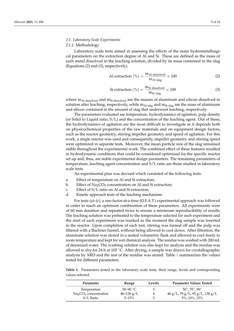
2.1. Laboratory Scale Experiments2.1.1. Methodology
Laboratory scale tests aimed at assessing the effects of the main hydrometallurgi-cal parameters on the extraction degree of Al and Si. These are defined as the mass ofeach metal dissolved in the leaching solution, divided by its mass contained in the slag(Equations (2) and (3), respectively).
Al extraction (%) =mAl dissolved
mAl slag× 100 (2)
Si extraction (%) =mSi dissolved
mSi slag× 100 (3)
where mAl dissolved and mSi dissolved are the masses of aluminum and silicon dissolved insolution after leaching, respectively, while mAl slag and mSi slag are the mass of aluminumand silicon contained in the amount of slag that underwent leaching, respectively.
The parameters evaluated are temperature, hydrodynamics of agitation, pulp density(or Solid to Liquid ratio, S/L) and the concentration of the leaching agent. Out of these,the hydrodynamics of agitation are the most difficult to investigate as it depends bothon physicochemical properties of the raw materials and on equipment design factors,such as the reactor geometry, stirring impeller geometry and speed of agitation. For thiswork, a single reactor was used and consequently, impeller geometry and stirring speedwere optimized in separate tests. Moreover, the mean particle size of the slag remainedstable throughout the experimental work. The combined effect of these features resultedin hydrodynamic conditions that could be considered optimized for the specific reactorset up and, thus, are stable experimental design parameters. The remaining parameters oftemperature, leaching agent concentration and S/L ratio are those studied in laboratoryscale tests.
An experimental plan was devised which consisted of the following tests:
a. Effect of temperature on Al and Si extraction;b. Effect of Na2CO3 concentration on Al and Si extraction;c. Effect of S/L ratio on Al and Si extraction;d. Kinetic approach tests of the leaching mechanism.
For tests (a)–(c), a one-factor-at-a-time (O.F.A.T.) experimental approach was followedin order to reach an optimum combination of these parameters. All experiments wereof 60 min duration and repeated twice to ensure a minimum reproducibility of results.The leaching solution was preheated to the temperature selected for each experiment andthe start of each experiment was marked as the moment the slag sample was insertedin the reactor. Upon completion of each test, stirring was turned off and the pulp wasfiltered with a Buchner funnel, without being allowed to cool down. After filtration, thealuminate solution was stored in a sealed volumetric flask and allowed to cool freely toroom temperature and kept for wet chemical analysis. The residue was washed with 200 mLof deionized water. The washing solution was also kept for analysis and the residue wasallowed to dry for 24 h at 105 ◦C. After drying, a sample was drawn for crystallographicanalysis by XRD and the rest of the residue was stored. Table 1 summarizes the valuestested for different parameters.
Table 1. Parameters tested in the laboratory scale tests, their range, levels and correspondingvalues selected.
Parameter Range Levels Parameter Values Tested
Temperature 50–90 ◦C 3 50◦, 70◦, 90◦
Na2CO3 concentration 46–138 g/L 4 46 g/L, 55 g/L, 92 g/L, 138 g/LS/L Ratio 5–15% 3 5%, 10%, 15%
Minerals 2021, 11, 896 6 of 24
Concerning the selection of values for Na2CO3 concentration, the selection was chosenaccording to the theoretical molar amount of Na2CO3 needed for complete reaction of thecorresponding carbonate ion content with the Ca content of the slag. The minimum valueof 46 g/L corresponds to the theoretical amount, with the following values correspondingto an excess of 20% (55 g/L), 100% (92 g/L) and 200% (138 g/L).
In the case of the kinetic approach tests (d), full scale leaching was conducted accordingto the procedure described before. All hydrometallurgical parameters remained stablein these tests, besides the parameter of leaching duration. It was selected to perform5 min, 15 min and 60 min leaching tests. Al and Si extractions were estimated in thealuminate solution and the residues were examined by XRD after being dried according tothe procedures described earlier. The only difference between the kinetic approach testsand the O.F.A.T. methodology was that the washing solutions were not stored for analysisafterwards in the former.
2.1.2. Equipment and Materials Used
Leaching work was performed with a custom reactor set up. The body of the reactor,besides the lid, was built from parts of a Parr™ 4563 model. For this work, the reactor lidwas replaced by a custom Teflon lid, suitable for leaching tests at atmospheric pressure. Inmore detail, the reactor set-up consisted of a 600 mL capacity vessel made from Inconelalloy, a heating mantle, and the Teflon lid. The lid was built with openings and socketswhich allowed for: (a) attaching a condenser for condensing vapors, (b) the immersion of athermocouple and mechanical stirrer (c) the insertion of the solid sample, (d) the drawingof pulp samples during leaching and (e) the immersion of electrodes for pH measurement.Heating and stirring were controlled by a PLC unit. All leaching tests were performedunder atmospheric pressure conditions.
Elemental chemical analysis of the aqueous solutions produced was performed in aPerkinElmer™ PinAAcle 900T Atomic Adsorption Spectrometer. Crystallographic analysisof the solid samples was performed in a Malvern-PANalytical™ X ‘Pert Pro diffractometer,with CuKa radiation (V = 40 KV και I = 30 mA). Phase identification was performedwith Bruker™ Diffrac EVA software and use of ICDD™ Diffraction databases PDF-4+ και
PDF-4 Minerals.The raw material used for the laboratory scale experiments is a slag produced from
reductive smelting of Greek BR and was produced into a 100 KVA DC laboratory scaleelectric arc furnace, operated at about 5 kW, and smelted batch wise in a graphite crucible.Details about the experimental procedure and properties of the slag are discussed in aprevious publication [28]. After separation of slag from metal, the former was preparedfor subsequent hydrometallurgical treatment. The slag was first mechanically crashedto cm size particles and then milled in a LABTECHNICS LM2 Laboratory PulverizingMill with a target size of passing through the 0.3 mm sieve. Sampling of the milled slagwas performed using a riffle splitter to ensure homogeneity and samples were drawn forchemical, crystallographic and particle size analysis of the slag.
Particle size analysis was performed by sieving of the dry material. The particlesize distribution curve is shown in Figure 2. It can be observed that 100% of the slagpasses through the 0.3 mm sieve. Moreover, the mean D50 of the material was calculatedgraphically from the particle size distribution curve and is also shown in Figure 2.
For the chemical analysis, slag samples were fused with a mixture of borate fluxesand the melt was dissolved in 10% HNO3 solution. The wet samples were analyzed byAtomic Adsorption Spectroscopy (AAS). The chemical analysis for the main elements,calculated in wt.% of their respective oxides is shown in Table 2. The carbon (in the formof graphite) content of the slag was estimated by a LECO elemental analyzer and is alsoshown in Table 2.

Minerals 2021, 11, 896 7 of 24
Figure 2. Particle size distribution and corresponding graphical estimation of the D50 of the Ca-richslag used for the laboratory scale experiments of this study.
Table 2. Chemical analysis of the Ca-rich slag used for the laboratory scale experiments of this study.
Component CaO Al2O3 SiO2 TiO2 FeO Na2O MgO Cr2O3 C Others
Content 50.8% 26.3% 10.4% 5.7% 1.2% 2.4% 0.8% 0.11% 1.7% 0.7%
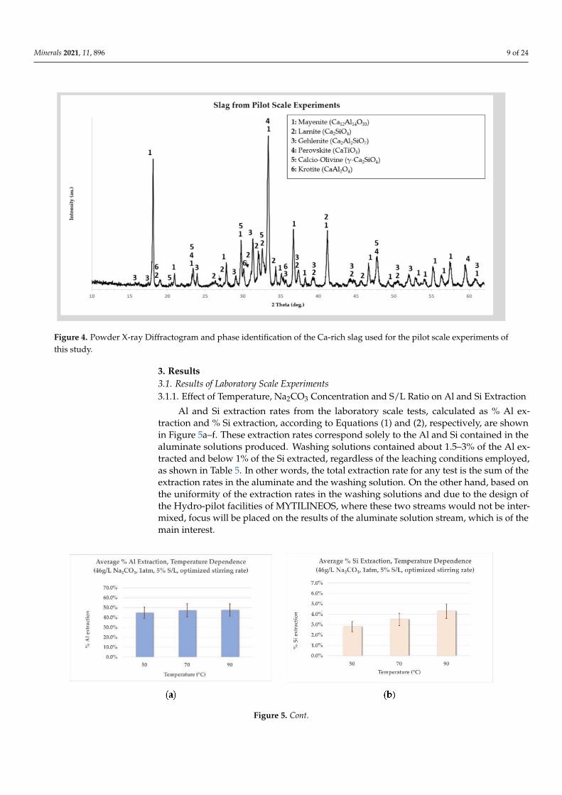
Finally, crystallographic analysis was performed by Powder X-ray Diffraction. ThePowder X-ray Diffractogram of the slag is shown in Figure 3. The alumina content of theslag is found on the calcium aluminate phases of C12A7 and C3A. Perovskite is the onlyTi-bearing phase, while silicon is found in the form of two modifications of the C2S phase.Finally, graphite and traces of metallic Fe are also observed. The dusting effect related tothe γ-C2S (calcio-olivine) was never observed, hence the need for crushing and milling ofthe slag.
Figure 3. Powder X-ray Diffractogram and phase identification of the Ca-rich slag used for thelaboratory scale experiments of this study.
Minerals 2021, 11, 896 8 of 24
2.2. Pilot Scale Experiments
At the Pyro-pilot facilities of MYTILINEOS, Greek BR was smelted in 1MVA ElectricArc Furnace (EAF) to produce pig iron and calcium aluminate slag. The slag was thentreated at the Hydro-pilot facilities of MYTILINEOS. An 800 L Polypropylene leachingreactor, with a Halar coated steel blade agitator and emerged heating and cooling coilsfor temperature control, was employed. The percent extractions of Al2O3 and SiO2 wereestimated based on comparing the chemical analyses of these compounds in the solidresidue of the leaching process with their respective amounts before leaching.
All solids were analyzed at MYTILINEOS by fused bead XRF analysis, using an ARL™PERFORM’X Sequential X-ray Fluorescence Spectrometer. Crystallographic analysis of theslag was performed with the same instrument used for the analysis of the laboratory scaletests (described in Section 2.1.2).
For the pyrometallurgical pilot work, BR was dried in a static bed dryer before feedingand was mixed with 300 kg CaO/t BR and 180 kg metallurgical coke/t BR. Chemicalanalysis of these raw materials is shown in Table 3. This feed was smelted in 300–500 kgbatches in the EAF. Smelting duration was 74 min and the maximum temperature reachedwas 1700 ◦C.
Table 3. Chemical analysis of the materials used in pilot scale pyrometallurgical tests.
Material Al2O3%
Fe2O3%
CaO%
SiO2%
TiO2%
Na2O%
MgO%
CaCO3%
C%
S%
P%
LOI%
Others%
BR 19.75 42.74 9.42 6.98 5.28 2.92 - - - - - 9.42 3.44Lime - - 96.37 - - - 0.63 0.93 - - - - 2.07Coke 3.11 - 1.28 3.74 - - - - 82.62 0.22 0.04 - 8.99
The pig iron produced was casted in ingots. The slag was casted in 100 L steel ladlesand left to slowly solidify. Subsequently, the slag was crushed and milled using a series ofjaw crushers, cylinder crushers and disk mill to attain a−500 µm particle size. The chemicalanalysis of the slag is shown in Table 4 and its crystallographic analysis in Figure 4.
For the leaching work performed in pilot scale, the reactor was filled with 0.5 m3 of120 g/L Na2CO3 solution and heated to 70 ◦C. A total of 50 kg of slag was added to thereactor (10% S/L) and the pulp was retained in the reactor for 30 min. These conditions weresuggested after the laboratory scale tests were completed (results described in Section 3.1).Subsequently, the resulting slurry, consisting of the aluminate solution and the leachingresidue, was transferred to a holding tank and a new leaching cycle followed. Two runs(termed Run A and Run B), each consisting of 3 leaching cycles (150 kg of slag treated intotal at each Run) were performed. The slurry produced after each run was filtered at 6 barpressure in a filter-press, with filter-clothes of 10 µm pore size, producing an aluminatesolution and a filter cake (grey mud).
Table 4. Chemical analysis of the Ca-rich slag produced and used for the pilot scale experiments of this study.
Component Al2O3 % Fe2O3% CaO % SiO2 % TiO2 % Na2O % V2O5 % SO3 % LOI % Others
Content 32.00 0.89 36.30 13.10 4.28 1.38 0.08 0.61 1.57 9.79
Minerals 2021, 11, 896 9 of 24
Figure 4. Powder X-ray Diffractogram and phase identification of the Ca-rich slag used for the pilot scale experiments ofthis study.
3. Results3.1. Results of Laboratory Scale Experiments3.1.1. Effect of Temperature, Na2CO3 Concentration and S/L Ratio on Al and Si Extraction
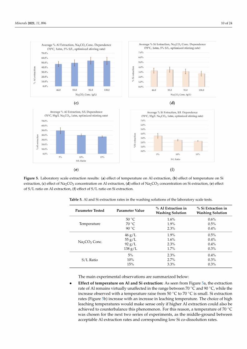
Al and Si extraction rates from the laboratory scale tests, calculated as % Al ex-traction and % Si extraction, according to Equations (1) and (2), respectively, are shownin Figure 5a–f. These extraction rates correspond solely to the Al and Si contained in thealuminate solutions produced. Washing solutions contained about 1.5–3% of the Al ex-tracted and below 1% of the Si extracted, regardless of the leaching conditions employed,as shown in Table 5. In other words, the total extraction rate for any test is the sum of theextraction rates in the aluminate and the washing solution. On the other hand, based onthe uniformity of the extraction rates in the washing solutions and due to the design ofthe Hydro-pilot facilities of MYTILINEOS, where these two streams would not be inter-mixed, focus will be placed on the results of the aluminate solution stream, which is of themain interest.
Figure 5. Cont.
Minerals 2021, 11, 896 10 of 24
Figure 5. Laboratory scale extraction results: (a) effect of temperature on Al extraction, (b) effect of temperature on Siextraction, (c) effect of Na2CO3 concentration on Al extraction, (d) effect of Na2CO3 concentration on Si extraction, (e) effectof S/L ratio on Al extraction, (f) effect of S/L ratio on Si extraction.
Table 5. Al and Si extraction rates in the washing solutions of the laboratory scale tests.
Parameter Tested Parameter Value % Al Extraction inWashing Solution
% Si Extraction inWashing Solution
Temperature50 ◦C 1.6% 0.6%70 ◦C 1.9% 0.5%90 ◦C 2.3% 0.4%
Na2CO3 Conc.
46 g/L 1.9% 0.5%55 g/L 1.6% 0.4%92 g/L 2.3% 0.4%
138 g/L 1.7% 0.3%
S/L Ratio5% 2.3% 0.4%10% 2.7% 0.3%15% 3.3% 0.3%
The main experimental observations are summarized below:
• Effect of temperature on Al and Si extraction: As seen from Figure 5a, the extractionrate of Al remains virtually unaffected in the range between 70 ◦C and 90 ◦C, while theincrease observed with a temperature raise from 50 ◦C to 70 ◦C is small. Si extractionrates (Figure 5b) increase with an increase in leaching temperature. The choice of highleaching temperatures would make sense only if higher Al extraction could also beachieved to counterbalance this phenomenon. For this reason, a temperature of 70 ◦Cwas chosen for the next two series of experiments, as the middle-ground betweenacceptable Al extraction rates and corresponding low Si co-dissolution rates.
Minerals 2021, 11, 896 11 of 24
• Effect of Na2CO3 concentration on Al and Si extraction: Employing a small excessof Na2CO3 (20% excess, 55 g/L) has practically the same effect on the Al extraction rateas employing a bigger excess (100% excess, 92 g/L), as shown in Figure 5c. Moreover,a larger excess of Na2CO3 (200% excess, 138 g/L) shows no further increase in Alextraction rates. As shown on Graph 5d, Si extraction rates remain constant throughoutthe range of Na2CO3 concentrations tested. This consistency could prove importantfor further modelling of the process in pilot scale. According to the results mentionedabove, an excess of 20% Na2CO3 is selected for the last series of experiments.
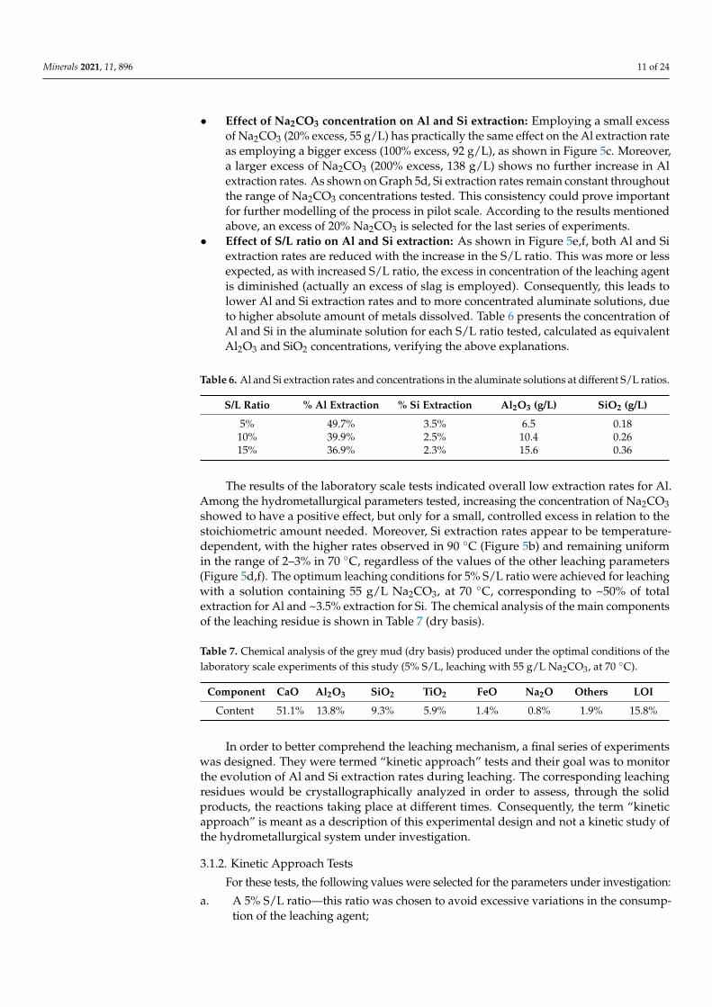
• Effect of S/L ratio on Al and Si extraction: As shown in Figure 5e,f, both Al and Siextraction rates are reduced with the increase in the S/L ratio. This was more or lessexpected, as with increased S/L ratio, the excess in concentration of the leaching agentis diminished (actually an excess of slag is employed). Consequently, this leads tolower Al and Si extraction rates and to more concentrated aluminate solutions, dueto higher absolute amount of metals dissolved. Table 6 presents the concentration ofAl and Si in the aluminate solution for each S/L ratio tested, calculated as equivalentAl2O3 and SiO2 concentrations, verifying the above explanations.
Table 6. Al and Si extraction rates and concentrations in the aluminate solutions at different S/L ratios.
S/L Ratio % Al Extraction % Si Extraction Al2O3 (g/L) SiO2 (g/L)
5% 49.7% 3.5% 6.5 0.1810% 39.9% 2.5% 10.4 0.2615% 36.9% 2.3% 15.6 0.36
The results of the laboratory scale tests indicated overall low extraction rates for Al.Among the hydrometallurgical parameters tested, increasing the concentration of Na2CO3showed to have a positive effect, but only for a small, controlled excess in relation to thestoichiometric amount needed. Moreover, Si extraction rates appear to be temperature-dependent, with the higher rates observed in 90 ◦C (Figure 5b) and remaining uniformin the range of 2–3% in 70 ◦C, regardless of the values of the other leaching parameters(Figure 5d,f). The optimum leaching conditions for 5% S/L ratio were achieved for leachingwith a solution containing 55 g/L Na2CO3, at 70 ◦C, corresponding to ~50% of totalextraction for Al and ~3.5% extraction for Si. The chemical analysis of the main componentsof the leaching residue is shown in Table 7 (dry basis).
Table 7. Chemical analysis of the grey mud (dry basis) produced under the optimal conditions of thelaboratory scale experiments of this study (5% S/L, leaching with 55 g/L Na2CO3, at 70 ◦C).
Component CaO Al2O3 SiO2 TiO2 FeO Na2O Others LOI
Content 51.1% 13.8% 9.3% 5.9% 1.4% 0.8% 1.9% 15.8%
In order to better comprehend the leaching mechanism, a final series of experimentswas designed. They were termed “kinetic approach” tests and their goal was to monitorthe evolution of Al and Si extraction rates during leaching. The corresponding leachingresidues would be crystallographically analyzed in order to assess, through the solidproducts, the reactions taking place at different times. Consequently, the term “kineticapproach” is meant as a description of this experimental design and not a kinetic study ofthe hydrometallurgical system under investigation.
3.1.2. Kinetic Approach Tests
For these tests, the following values were selected for the parameters under investigation:
a. A 5% S/L ratio—this ratio was chosen to avoid excessive variations in the consump-tion of the leaching agent;
Minerals 2021, 11, 896 12 of 24
b. Na2CO3 concentration of 46 g/L, which corresponds to the theoretical amountneeded for complete reaction between the CaO content of the slag and the carbonatecontent of the solution (according to Equation (1));
c. Tests were performed at 70 ◦C and 90 ◦C, in order to further assess the behavior of Siduring leaching, which appears to be temperature-dependent.
First, the extraction rates of Al and Si, in relation to the leaching duration, for bothtemperatures, are presented, followed by the results of the crystallographic analysis of theleaching residues.
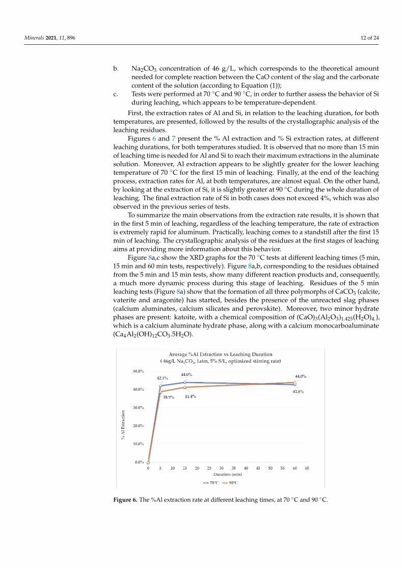
Figures 6 and 7 present the % Al extraction and % Si extraction rates, at differentleaching durations, for both temperatures studied. It is observed that no more than 15 minof leaching time is needed for Al and Si to reach their maximum extractions in the aluminatesolution. Moreover, Al extraction appears to be slightly greater for the lower leachingtemperature of 70 ◦C for the first 15 min of leaching. Finally, at the end of the leachingprocess, extraction rates for Al, at both temperatures, are almost equal. On the other hand,by looking at the extraction of Si, it is slightly greater at 90 ◦C during the whole duration ofleaching. The final extraction rate of Si in both cases does not exceed 4%, which was alsoobserved in the previous series of tests.
To summarize the main observations from the extraction rate results, it is shown thatin the first 5 min of leaching, regardless of the leaching temperature, the rate of extractionis extremely rapid for aluminum. Practically, leaching comes to a standstill after the first 15min of leaching. The crystallographic analysis of the residues at the first stages of leachingaims at providing more information about this behavior.
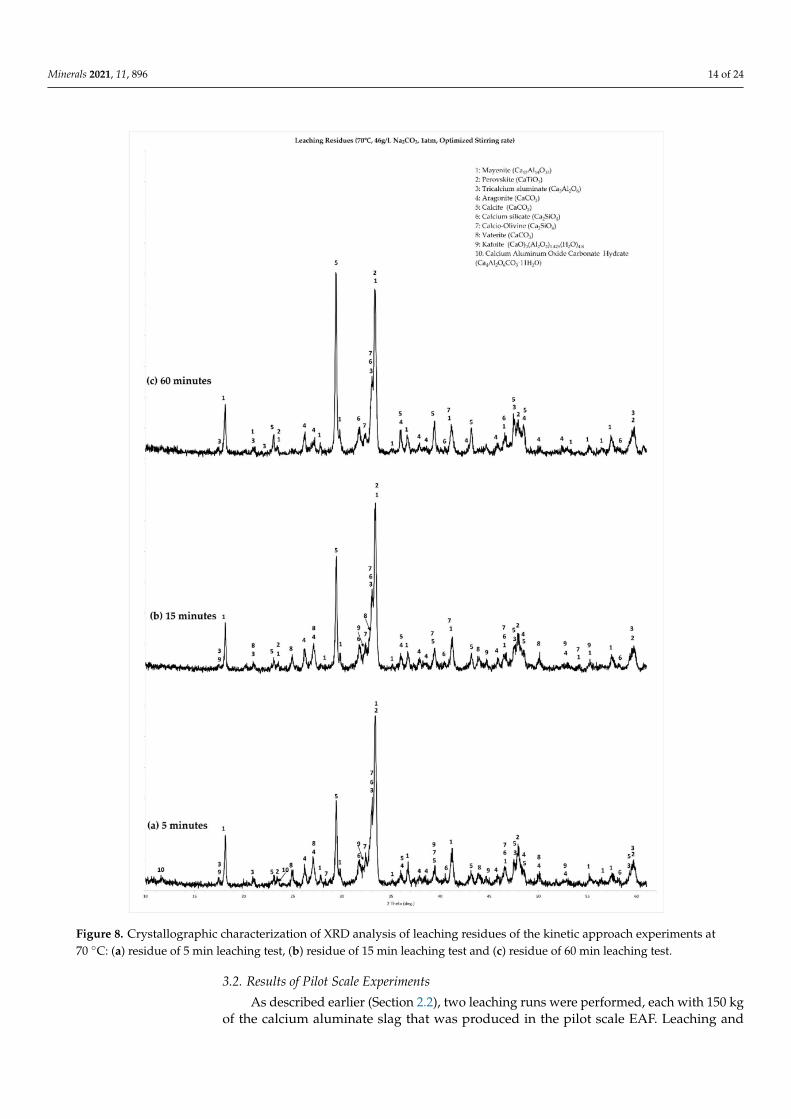
Figure 8a,c show the XRD graphs for the 70 ◦C tests at different leaching times (5 min,15 min and 60 min tests, respectively). Figure 8a,b, corresponding to the residues obtainedfrom the 5 min and 15 min tests, show many different reaction products and, consequently,a much more dynamic process during this stage of leaching. Residues of the 5 minleaching tests (Figure 8a) show that the formation of all three polymorphs of CaCO3 (calcite,vaterite and aragonite) has started, besides the presence of the unreacted slag phases(calcium aluminates, calcium silicates and perovskite). Moreover, two minor hydratephases are present: katoite, with a chemical composition of (CaO)3(Al2O3)1.425(H2O)4.),which is a calcium aluminate hydrate phase, along with a calcium monocarboaluminate(Ca4Al2(OH)12CO3.5H2O).
Figure 6. The %Al extraction rate at different leaching times, at 70 ◦C and 90 ◦C.

Minerals 2021, 11, 896 13 of 24
Figure 7. The %Si extraction rate at different leaching times, at 70 ◦C and 90 ◦C.
With the progression of leaching, at 15 min duration (Figure 8b), the calcium monocar-bonate aluminate phase is no longer observed, while katoite persists. At the same time thepeaks of calcite intensify. Finally, after 60 min of leaching (Figure 8c), all hydrate phases,along with vaterite, are no longer observed. The main reaction products remaining arecalcite and aragonite. The same succession of phenomena was observed also at the residuesfrom the 90 ◦C leaching tests, the only difference being the persistence of the calciummonocarboaluminate phase in the residue of the 15 min leaching test.
3.1.3. Summary of Observations and Suggestions for the Pilot Work Tests
Laboratory scale work showed that significant optimizations were needed in orderto increase the alumina yield of leaching. These optimizations were implemented in thedesign process of the planned pilot scale work. Concerning the issue of slag composition,the main observation, verified by the crystallographic analysis, was that the excess of CaOused to suppress C2AS formation has a negative effect on extraction, due to the formation ofC3A. As a result, for the pilot scale pyrometallurgical work, the amount of CaO used as fluxwas reduced. This is reflected in the chemical (Table 3) and crystallographic composition(Figure 3) of the slag produced in pilot scale. This pilot scale slag contained about 36%CaO (compared to ~50% CaO of the laboratory scale slag). Some C2AS is formed, but thelowered CaO content favored the formation of CA.
Concerning the observations of the leaching tests, it was shown, first of all, that in-creased leaching temperatures and Na2CO3 concentrations are not needed for leachingcalcium aluminate slags. Temperatures of 70 ◦C and a minor excess of Na2CO3 proved suf-ficient for extracting about 50% of the Al contained in the laboratory slag. Si co-dissolutionis inevitable, though its extent appears to be easily predictable and temperature dependent.Moreover, it appears that maximum Al extraction is achieved fast (<20 min); as a result,depending on the pilot plants operative conditions, a leaching duration of less than 1 h issuggested. A key issue for pilot scale work is the fact that low S/L ratios are not desirableon operating and cost-effective grounds. According to these considerations, the conditionssuggested for pilot plant work were as follows:
• Concentration of leaching agent: 120 g/L Na2CO3 (corresponding to a small excessof Na2CO3 in relation to the CaO content of the slag);
• S/L ratio: 10%;• Leaching temperature: 70 ◦C;• Duration: Less than 1 h (exact value defined by the operating capabilities of the
pilot plant).
Minerals 2021, 11, 896 14 of 24
Figure 8. Crystallographic characterization of XRD analysis of leaching residues of the kinetic approach experiments at70 ◦C: (a) residue of 5 min leaching test, (b) residue of 15 min leaching test and (c) residue of 60 min leaching test.
3.2. Results of Pilot Scale Experiments
As described earlier (Section 2.2), two leaching runs were performed, each with 150 kgof the calcium aluminate slag that was produced in the pilot scale EAF. Leaching and

Minerals 2021, 11, 896 15 of 24
solid/liquid separation of a 150 kg of slag produced approximately 1380 L of aluminatesolution and 114.9 kg of filtercake (grey mud), on a dry basis, in the first trial (Run A)and 1310 L of aluminate solution and 128.8 kg of grey mud, on a dry basis, in the secondtrial (Run B). The percent yield of grey mud in each run and the corresponding chemicalanalysis are shown in Table 8.
Table 8. Percent yield and corresponding chemical analysis of the produced filtercakes (grey muds) from the pilot scaletests.
Materialon DryBasis
Yield % Al2O3 % Fe2O3 % CaO % SiO2 % TiO2 % Na2O % V2O5 % SO3 % LOI %
Grey Mud(Run A) 76.6% 10.50 1.97 45.90 11.80 6.15 5.37 0.14 0.26 16.70
Grey Mud(Run B) 85.8% 9.05 2.04 42.90 11.60 5.18 5.81 0.08 0.24 21.90
According to the data of Table 8, the leaching process achieved 72.08% and 64.56%aluminum extraction rates in the two tests, respectively, or 68.23% on average. Siliconextraction was limited to 1.95% and 1.85%, respectively, or 1.90% on average. The resultingaluminate solutions had 24.56 g/L and 23.65 g/L Al2O3 and will be used for aluminaprecipitation tests.
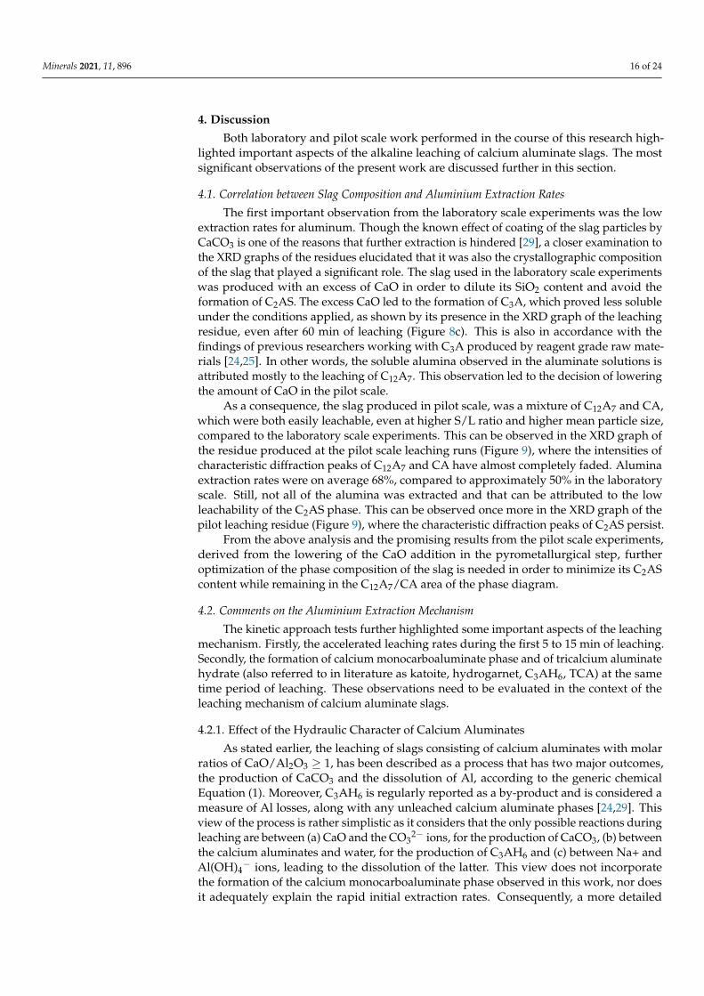
The crystallographic analysis of the grey mud produced in the pilot scale leachingruns is shown in Figure 9. The first observation is that C12A7 and CA are present only asminor phases in the residue, a fact that is related to the higher Al extraction rates achieved.Moreover, C2AS is still present in the residue as one of the main components, suggestingthat the aluminum bound in this phase was not leached. Finally, a small fraction of the Alcontent of the slag is precipitated in the form of katoite. Even with the unleached C2ASand the precipitation of katoite, aluminum extraction rates were overall higher due to theincorporation of the suggestions based on the laboratory scale tests.
Figure 9. Powder X-ray Diffractogram and phase identification of the grey mud produced at the pilot scale leachingexperiments of this study.
Minerals 2021, 11, 896 16 of 24
4. Discussion
Both laboratory and pilot scale work performed in the course of this research high-lighted important aspects of the alkaline leaching of calcium aluminate slags. The mostsignificant observations of the present work are discussed further in this section.
4.1. Correlation between Slag Composition and Aluminium Extraction Rates
The first important observation from the laboratory scale experiments was the lowextraction rates for aluminum. Though the known effect of coating of the slag particles byCaCO3 is one of the reasons that further extraction is hindered [29], a closer examination tothe XRD graphs of the residues elucidated that it was also the crystallographic compositionof the slag that played a significant role. The slag used in the laboratory scale experimentswas produced with an excess of CaO in order to dilute its SiO2 content and avoid theformation of C2AS. The excess CaO led to the formation of C3A, which proved less solubleunder the conditions applied, as shown by its presence in the XRD graph of the leachingresidue, even after 60 min of leaching (Figure 8c). This is also in accordance with thefindings of previous researchers working with C3A produced by reagent grade raw mate-rials [24,25]. In other words, the soluble alumina observed in the aluminate solutions isattributed mostly to the leaching of C12A7. This observation led to the decision of loweringthe amount of CaO in the pilot scale.
As a consequence, the slag produced in pilot scale, was a mixture of C12A7 and CA,which were both easily leachable, even at higher S/L ratio and higher mean particle size,compared to the laboratory scale experiments. This can be observed in the XRD graph ofthe residue produced at the pilot scale leaching runs (Figure 9), where the intensities ofcharacteristic diffraction peaks of C12A7 and CA have almost completely faded. Aluminaextraction rates were on average 68%, compared to approximately 50% in the laboratoryscale. Still, not all of the alumina was extracted and that can be attributed to the lowleachability of the C2AS phase. This can be observed once more in the XRD graph of thepilot leaching residue (Figure 9), where the characteristic diffraction peaks of C2AS persist.
From the above analysis and the promising results from the pilot scale experiments,derived from the lowering of the CaO addition in the pyrometallurgical step, furtheroptimization of the phase composition of the slag is needed in order to minimize its C2AScontent while remaining in the C12A7/CA area of the phase diagram.
4.2. Comments on the Aluminium Extraction Mechanism
The kinetic approach tests further highlighted some important aspects of the leachingmechanism. Firstly, the accelerated leaching rates during the first 5 to 15 min of leaching.Secondly, the formation of calcium monocarboaluminate phase and of tricalcium aluminatehydrate (also referred to in literature as katoite, hydrogarnet, C3AH6, TCA) at the sametime period of leaching. These observations need to be evaluated in the context of theleaching mechanism of calcium aluminate slags.
4.2.1. Effect of the Hydraulic Character of Calcium Aluminates
As stated earlier, the leaching of slags consisting of calcium aluminates with molarratios of CaO/Al2O3 ≥ 1, has been described as a process that has two major outcomes,the production of CaCO3 and the dissolution of Al, according to the generic chemicalEquation (1). Moreover, C3AH6 is regularly reported as a by-product and is considered ameasure of Al losses, along with any unleached calcium aluminate phases [24,29]. Thisview of the process is rather simplistic as it considers that the only possible reactions duringleaching are between (a) CaO and the CO3
2− ions, for the production of CaCO3, (b) betweenthe calcium aluminates and water, for the production of C3AH6 and (c) between Na+ andAl(OH)4
− ions, leading to the dissolution of the latter. This view does not incorporatethe formation of the calcium monocarboaluminate phase observed in this work, nor doesit adequately explain the rapid initial extraction rates. Consequently, a more detailed

Minerals 2021, 11, 896 17 of 24
approach to explaining the chemical phenomena taking place is needed. The starting pointfor the discussion is the inherent physicochemical properties of the calcium aluminates.
A defining feature of the various calcium aluminates that is exploited in their applica-tions as cementitious phases is their hydraulic character and their participation in hydrationreactions. The products of these hydration reactions are various calcium aluminate hydratephases. Since the hydrometallurgical process under examination involves the reaction ofcalcium aluminates in an aqueous phase, it is certain that their hydraulic character alsoaffects their leaching behavior.
The hydration of any hydraulic phase is an irreversible process driven by the lowersolubility of the hydrate phase formed, compared to the solubility of the solid being dis-solved. Therefore, in such systems, a competition takes place between two equilibriumstates that cannot be attained at the same time. The first one is the equilibrium betweenthe superficially hydroxylated solid and the aqueous phase, which is the driving forcefor the dissolution ions from the solid phase to the solution. The second one is the equi-librium between the hydrates and the aqueous phase, which is the driving force for theprecipitation of the hydrate phases. Put more simply, the competition between these twoequilibrium states reflects the competing processes of dissolution of the hydraulic solidsand precipitation of the hydrates [30].
The literature of hydration reactions of calcium aluminates and the properties of theirsolid products has been reviewed by H. Pöllmann [31]. The thermodynamically stablesolid phases in the system Al2O3–CaO–H2O are C3AH6 and Al(OH)3 (also referred toas AH3 in the literature of cements). These phases do not crystallize immediately butform through the transformation of metastable hydrate phases, by a process termed as the“conversion reaction”. The formation of the metastable phases is temperature-dependent.Furthermore, the rate of the conversion reaction is accelerated at higher temperatures. Thesedependencies are shown in Equations (4)–(8), describing the hydration reactions of CA atintermediate and higher temperatures (Equations (4), (5) and (7)) and the correspondingconversion reactions (Equations (6) and (8)):
Intermediate temperatures (15 ◦C–25 ◦C)
3CA + H2O (excess)→ CAH10 + C2AH8 (4)
2CA + 11H→ C2AH8 + AH3 (5)
2CAH10 → C2AH8 + AH3 + 9H (6)
Higher temperatures (>25 ◦C)
3CA + 12H→ C3AH6 + 2AH3 (7)
2C2AH8 → 2C3AH6 + AH3 + 9H (8)
The hydration of C12A7 is analogous to that of CA, forming similar hydrates, themain difference being the formation of C2AH8 even at low temperatures, due to the higherCaO/Al2O3 in the phase [32,33]. The hydration of C3A, which is a constituent of the slagused in the laboratory scale experiments, follows a different path due to the value of themolar CaO/Al2O3 ratio of this compound [32,34]. The reaction describing the formation ofthe metastable hydrate phases during C3A hydration is described by Equation (9) and thecorresponding conversion reaction is described by Equation (10):
2C3A + H2O (excess)→ C2AH8 + C4AH19 (9)
C2AH8 + C4AH19 → 2C3AH6 + 15H (10)
Most important to the present discussion is the description of the mechanism ofhydration of calcium aluminate phases. The mechanism of hydration of all calcium alumi-nates is a “dissolution–precipitation” mechanism or “through solution” mechanism [32,35].Though the mechanism applies to all basic calcium aluminate compounds, subtle differ-
Minerals 2021, 11, 896 18 of 24
ences exist between C3A and the other two calcium aluminates of interest to this study.First, the hydration of CA and C12A7 is briefly covered.
The moment CA (or C12A7) comes in contact with water or an aqueous solution, ahydroxylated surface layer forms, composed of Ca[Al(OH)4]2, also termed “superficiallyhydroxylated” calcium aluminate surface [30,36]. This surface dissolves in solution, expos-ing a fresh layer of anhydrous material, which in turn will be hydroxylated and dissolved.As a result of this process, relatively high concentrations of Ca2+ and Al(OH)4
− ions areobserved in the solution for a period of time before the precipitation of the hydrates takesplace (induction period). When the solution reaches a supersaturation level, the metastablecalcium aluminate hydrate phases will precipitate massively out of the solution. Thedegree of hydration of calcium aluminates can be increased by increasing the fineness ofthe anhydrous grains [37]. The conversion reaction of the metastable to stable phases alsofollows the same mechanism (“through solution”) and it initiates with the nucleation of thefirst C3AH6 [38]. The solubilities of the metastable hydrates are higher than the solubilityof C3AH6 and the driving force of its precipitation is the dissolution of the metastablehydrates. Both metastable phases are more soluble in increased temperatures, which favorsthe progression of the conversion reaction for the production of C3AH6 and AH3 [31].
In the case of the C3A phase it has been observed that the first hydration products forman amorphous gel-like material, which then converts to the metastable phases according toEquation (9) [39]. Then, follows the conversion reaction as in the case of the other calciumaluminates. It can be observed that reaction (10) does not lead to the release of AH3 as isthe case of the conversion reactions of CA and C12A7 (Equations (6) and (8)).
The hydration reactivity of calcium aluminates appears to be playing an importantrole also in the hydrometallurgical process of aluminum leaching from these phases, whichtakes place in an aqueous solution of Na2CO3. The dissociation of Na2CO3 in alkalinesolutions can be presented according to Equation (11):
Na2CO3(s) 2Na+(aq) + CO2−
3(aq) (11)
In the first minutes of leaching, high aluminum extraction rates are observed, whichcan be directly related to the dissolution mechanism described above. In more detail,and for the case of C12A7 and CA, the hydroxylated Ca[Al(OH)4]2 layer that forms assoon as the slag particles come in contact with the Na2CO3 aqueous solution will dissolveaccording to Equation (12).
Ca[Al(OH)4]2 → Ca2+(aq) + 2Al(OH)−4 (aq) (12)
The leaching solution, having a considerable concentration in CO32−, will aid the dis-
solution process by consuming the Ca2+ ion initially dissolved, according to Equation (13)and consequently push the equilibrium of Equation (12) to the right.
Ca2+(aq) + CO2−
3 (aq) → CaCO3(s) (13)
According to Equation (13), by continuously reducing the concentration of Ca2+ ions insolution, the solution is not allowed to reach supersaturation with respect to the metastablehydrates, at least in the initial stages of leaching, when the concentration of CO3
2− ions is atits highest value. At the same time, as CO3
2− ions are removed by the formation of CaCO3,the amount of free Na+ ions increases, causticizing the solution. A second outcome of thisaction is that more Al(OH)4
− ions are allowed to remain in solution and not precipitate asAl(OH)3. In other words, the increase in free Na+ in solution pushes the equilibrium of thereaction described by Equation (14) to the side of the products.
Al(OH)3(s) + Na+(aq) + OH−
(aq) � Al(OH)−4(aq) + Na+(aq) (14)
Minerals 2021, 11, 896 19 of 24
Thus, the high extraction rates at the first minutes of leaching are significantly aided bythe inherent hydraulic properties of the leachable calcium aluminates (CA and C12A7). Asmentioned earlier, the hydration of C3A is different due to the formation of the amorphousgel-like phase on the surface of C3A particles. It is probable that the lower extraction ratesattributed to this phase are correlated to this phenomenon. Further research is needed toverify this suggestion.
The dissolution of the Ca[Al(OH)4]2 surface layer is not the only mechanism contribut-ing to the extraction of aluminum and the causticization of the solution. Another reactionis certain to be taking place between the hydroxylated Ca[Al(OH)4]2 surface of the calciumaluminate phases and the solution. This reaction on the solid/liquid interface is the oneleading to the surface precipitation of CaCO3 that has been described repeatedly in theliterature. This action could be described by an equation such as (15).
Ca[Al(OH)4]2 + CO2−3 (aq) → CaCO3(s) + 2Al(OH)−4 (aq) (15)
At this point, Equation (15) must be treated as a conceptual reaction and not the actualdescription of the CaCO3 precipitation process, which is dealt with in the next section.
Consequently, the high extraction rates during the initial stages of leaching could beattributed to the combined effect of two actions. The first action is the aqueous dissolutionof Ca2+ and Al(OH)4
− ions from the hydroxylated surface of the calcium aluminates, whichis an inherent property of the hydraulic character of these materials. The second action is areaction on the solid/liquid interface, which leads to the surface precipitation of CaCO3.These two leaching actions are analogous to the competing dissolution and precipitationactions that characterize the CaO–Al2O3–H2O system. The dissolution action is acceleratedby the presence of Na+ and CO3
2− ions of the leaching solution. Supersaturation of thesolution in relation to the metastable calcium aluminate hydrates is not reached in the firststages of leaching due to the continuous reaction of the Ca+ and CO3
2− ions. At the sametime, CaCO3 is precipitated, both through solution, according to Equation (13), and onthe surface of the slag particles, according to an action resembling the one described byEquation (15). The latter is the one that is progressively hindering further dissolution andis discussed next.
4.2.2. CaCO3 Formation through Causticization of the Aluminate Solution
Equation (15) describes a conceptual action because it isolates the dissolved CO32−
ions and does not take into consideration the remaining components of the solution. Inreality, as a consequence of the rapid dissolution described earlier, the composition of theaqueous solution changes rapidly from a purely Na2CO3 solution to an Al(OH)4
−–NaOH–Na2CO3 solution. As a result, additional chemical reactions are possible between thedissolved Al(OH)4
−, Na+ and CO32− ions and the hydroxylated calcium aluminate surface.
This group of reactions and the corresponding chemical system is already of interest to thealumina industry, with respect to the causticization of spent Bayer liquors. Consequently,studies of this system are relevant also to the leaching of calcium aluminates by aqueousNa2CO3 solutions.
Causticization is a process that aims at removing dissolved CO32− ions (expressed
as equivalent Na2CO3) from the spent aluminate solution by its reaction with Ca(OH)2,according to the generic Equation (16).
Ca(OH)2 (s) + CO2−3 (aq) → CaCO3(s) + 2OH−
(aq) (16)
The Al(OH)4− ions contained in the spent liquor are also known to react with lime to
produce the C3AH6 phase, according to Equation (17):
3Ca(OH)2 (s) + 2Al(OH)−4 (aq) → Ca3Al2(OH)12 (s) + 2OH−(aq) (17)
Minerals 2021, 11, 896 20 of 24
The overall goal of causticization is the effective removal of the CO32− ions while
minimizing aluminum precipitation as C3AH6. These are also the goals during the processof Na2CO3 leaching of the calcium aluminate slags, with the removal of the CO3
2− ionsaiding the continuous dissolution of Ca2+ and Al(OH)4
− ions from the hydroxylatedsurface of the calcium aluminate phases, and the resulting causticization allowing forincreased concentration of Al(OH)4
− ions in solution. On the other hand, reaction of theAl(OH)4
− ions with the hydroxylated calcium aluminate surface might lead to a reactionanalogous to Equation (17) and partial precipitation of the dissolved Al(OH)4
−. Therefore,a deeper look into the exact mechanism of causticization of aluminate solutions is needed.
The studies of G. I. D. Roach and S.P. Rosenberg et al. examined the chemical mecha-nism of Bayer causticization in more detail [40,41]. Both researchers identify quaternaryintermediate phases such as the calcium monocarboaluminate (Ca4Al2(OH)12CO3.5H2O)as a critical to effective causticization.
In more detail, an aluminate solution in contact with lime will produce the monocar-boaluminate phase according to the reaction described by Equation (18):
4Ca(OH)2 (s) + 2Al(OH)−4 (aq) + CO2−3 (aq) + 5H2O→ Ca4Al2(OH)12CO3·5H2O(s) + 4OH−
(aq) (18)
This is an effective causticizing reaction but also removes the aluminum from thesolution. In higher temperature (above 80 ◦C), the monocarboaluminate phase becomesunstable and reacts with CO3
2− ions to form CaCO3, according to Equation (19).
Ca4Al2(OH)12CO3·5H2O + 3CO2−3 (aq) � 4CaCO3(s) + 2Al(OH)−4 (aq) + 4OH−
(aq) + 5H2O (19)
This is considered the main causticization reaction leading to the precipitation ofCaCO3, while at the same time increasing causticity and aluminum concentration in thesolution. The reaction is written in equilibrium form because, upon cooling of a causticizedliquor in contact with a pulp containing CaCO3, the so-called “reversion reaction” takesplace and the calcium monocarboaluminate can reform [41]. The reversion reaction isobviously a reaction that also reduces the aluminum content in the solution.
In the present work, the identification of calcium monocarboaluminate in the residuesof the initial stages of leaching is suggestive of a similar causticization process takingplace. It was earlier suggested that the precipitation of CaCO3 on the surface of slagparticles indicates that a reaction on the solid/liquid interface also takes place, besidesthe dissolution of Ca2+ and Al(OH)4
−. This reaction can now be further understood as acausticization reaction similar to (18), with the calcium sites of the hydroxylated calciumaluminate surface acting as a causticizing agent. As leaching is studied in temperaturesover 70 ◦C, where the Equation (19) is favored, the surface precipitation of CaCO3 indicatesefficient causticization and removal of aluminum from the hydroxylated calcium aluminatesurface. Subsequently, the leaching/causticization action is gradually hindered and finallyterminated when the coating of all slag particles with CaCO3 has been completed.
The formation of C3AH6 can also proceed via the monocarboaluminate according tothe reaction described by Equation (20):
3Ca4Al2(OH)12CO3·5H2O + 2Al(OH)−4 (aq) + 4OH−(aq) → 4Ca3Al2(OH)12 (s) + 3CO2−
3 (aq) + 5H2O (20)
This reaction is indicative of poor causticization and actually removes aluminum fromthe solution and it is favored by high Al(OH)4
− and free NaOH concentration, and alsohindered by high carbonate ion concentrations [40,41].
The fact that both the calcium monocarboaluminate phase and the C3AH6 are observedin the residues during the first 15 min of leaching could possibly be explained by the relativeconcentration of CO3
2− and Al(OH)4− ions. Specifically, the consumption of CO3
2− ionsis high during the initial stages of leaching. A point is reached, depending on the initialNa2CO3 concentration of the leaching solution, that the relative concentration of CO3
2−
ions, Al(OH)4− ions and free NaOH favors the Equation (20) instead of (19). This would
suggest that an equilibrium between CaCO3 and C3AH6 exists and an excess of CO32−
ions is always needed to avoid the action described by Equation (20). Further investigationwill be performed in order to fully explain this phenomenon.
Minerals 2021, 11, 896 21 of 24
4.3. Comments the Silicon Co-Dissolution Phenomena
Both the laboratory and pilot scale tests showed that Si co-dissolution is inevitable, re-gardless of the slag composition, although lower extraction rates for Si were observed in thepilot scale (1.9% extraction rate compared to ~3.5% in laboratory scale). This phenomenoncan be attributed to the presence of the difficult to leach C2AS phase. Consequently, in itspresent form, the leaching process must be followed by a desilication process in order toproduce aluminate solutions of acceptable quality for the alumina industry.
Another aspect related to the Si chemistry of the leaching process under investigationis the probable Si removal action of C3AH being produced in the first stages of the leachingprocess. Pure C3AH is an end member of the hydrogrossular (HG) mineral series. In moredetail, the HG series has a general chemical formula of Ca3Al2(SiO4)3-x(OH)4x; 0 ≤ x ≤3.Its structure is made up of AlO6 octahedra and SiO4 tetrahedra linked with oxygen and thehydroxyl component (OH−). Si4+ is progressively replaced by 4H+ as x increases whichleads to the formation of (OH)4 groups. Katoite is the name designated for HG with an xvalue in the range 1.5 < x ≤3 [42].
This substitution of 4H+ by Si4+ is what gives katoite a desilication potential. JiongliangYuan and Yi Zhang have already studied C3AH as desilication agent and found it to besuperior for Si removal compared to lime [43]. The desilication action is described by thegeneric chemical Equation (21):
3CaO·Al2O3·6H2O + kSiO2(OH)2−2 → 3CaO·Al2O3·kSiO2·(6− 2k)H2O + 2kOH− + 2kH2O (21)
This action appears once again to be causticizing in nature and could also be con-tributing to the main causticization action (Equation (19)). Moreover, it is possible thatthe reduced Si co-dissolution rates observed during the pilot scale extraction tests couldbe attributed to this phases, which was observed in the crystallographic analysis of theresidue (Figure 9). It is probable that further optimizations of the leaching process couldincorporate this phenomenon in order to achieve the desired desilication of the solution.
5. Conclusions
Alkaline leaching with Na2CO3 aqueous solutions of calcium aluminate slags pro-duced from the reductive smelting of Greek BR was studied in two interconnecting stages.In the first stage of the work, which was performed in laboratory scale, a slag producedin laboratory scale was tested in a series of hydrometallurgical tests. This material wasprepared with excess of CaO as a flux in order to avoid the formation of C2AS which isunreactive in Na2CO3 solutions. The key parameters under investigation were the per-cent extraction rates of Al and Si from the slag. Analysis of the results of the laboratoryscale tests highlighted several issues for further optimizations in the second stage of thework, the pilot scale extraction tests. The most important findings from both stages of thisresearch are summarized below:
1. A calcium aluminate slag containing C12A7 and C3A, produced in laboratory scale,was leached in laboratory scale, under atmospheric pressure conditions. Leachingparameters tested were temperature, Na2CO3 concentration and S/L ratio, for op-timized stirring rate. The extraction rates for Al were low under all conditions andat best a 54% Al extraction, in 5% S/L ratio was achieved. Laboratory scale workalso highlighted high extraction rates for Al during the first 5 min of leaching, whichprogressively decelerate in the next 10 min, until no notable change in Al extraction isobserved after that point.
2. For the design of the second stage of the work in pilot scale, the observations ofthe laboratory scale tests were utilized, suggesting a slag with a reduced amount ofCaO and preferably containing a mixture of C12A7 and CA as the calcium aluminatephases. Moreover, leaching should be performed in moderate temperature (70 ◦C),for a short duration (<1 h) and with a Na2CO3 concentration not exceeding 120 g/Lfor a 10% S/L. The results of the pilot scale work confirmed the validity of the abovesuggestions, with alumina extraction reaching 68%, in 10% S/L ratio.
Minerals 2021, 11, 896 22 of 24
3. Si co-dissolution always occurred, both in the laboratory and the pilot scale experi-ments, at extraction rates of 3% and 1.9%, respectively. Desilication of the aluminatesolution is needed.
4. Based on the results of laboratory leaching tests that were performed at 70 ◦C and90 ◦C, for different leaching times (kinetic approach tests) the Al extraction mecha-nism was further explained. Al extraction rates observed are the net result of twomechanisms. The first is a mechanism of direct dissolution of Al into the solution,due to the hydraulic character of calcium aluminate phases. In an aqueous solutioncontaining no other ions, dissolution would continue until supersaturation in relationto the metastable calcium aluminate hydrates. In the case of the aqueous Na2CO3solutions, this supersaturation is not reached due to the reaction of CaCO3 formationthrough solution (Equation (12)). Moreover, the removal of CO3
2− ions from thesolution increases the causticity (causticization) due to the increase in free Na+ ions,which in turn leads to an increase in dissolved Al(OH)4
−, as is observed in the first5 min of leaching (Figure 6).
The second mechanism of Al extraction is a causticization mechanism that becomesprogressively more dominant, as the concentration of Al(OH)4
− in the solution increases.As in the case of spent Bayer liquor causticization, the present leaching solution containingAl(OH)4
−–NaOH–Na2CO3 reacts with the hydroxylated Ca sites on the slag particles pro-ducing calcium monocarboaluminate (Figure 8a), according to Equation (18). Subsequently,calcium monocarboaluminate reacts with the dissolved CO3
2− ions, further dissolvingAl(OH)4
− and at the same time precipitating CaCO3 on the surface of slag particles accord-ing to Equation (19). This action is responsible for the decelerating extraction rates, andafter about 15 min of leaching, further extraction is ceased as the particles are completelycoated with CaCO3.
Author Contributions: Conceptualization, M.V., E.B. and D.P.; methodology, E.B., P.D. and M.V.;software, M.V.; validation, M.V., E.B. and D.P.; formal analysis, M.V., E.G. and P.D.; investigation,A.B., E.B., P.D. and M.V.; resources, E.B. and D.P.; writing—original draft preparation, M.V. and E.B.;writing—review and editing, E.B., E.G., D.P.; visualization, M.V., E.B. and A.B.; supervision, E.B.and D.P.; project administration, M.V.; funding acquisition, E.B. and D.P. All authors have read andagreed to the published version of the manuscript.
Funding: Research funded from European Community’s Horizon2020 Programme REMOVAL(H2020/2014-2020/No.77646). This publication reflects only the authors’ view, exempting the Com-munity from any liability.
Data Availability Statement: Data supporting research work can be found from M.V.
Acknowledgments: The authors would like to acknowledge the support of Alexandra Alexandriand Dimitrios Kotsanis, members of the Laboratory of Metallurgy of NTUA, who performed thechemical and crystallographic analyses of the samples presented in this work. All laboratory scalework was performed in the facilities and with the equipment of the Laboratory of Metallurgy ofNTUA. The equipment for crystallographic analysis of solid samples was provided by the HellenicSurvey of Geology and Mineral Exploration (https://www.igme.gr/).
Conflicts of Interest: The authors declare no conflict of interest. The funders had no role in the designof the study; in the collection, analyses or interpretation of data; in the writing of the manuscript, orin the decision to publish the results.
References1. Ujaczki, E.; Feigl, V.; Molnar, M.; Cusack, P.; Curtin, T.; Courtney, R.; O’Donoghue, L.; Davris, P.; Hugi, C.; Evangelou, M.W.;
et al. Re-using bauxite residues: Benefits beyond (critical raw) material recovery. J. Chem. Technol. Biotechnol. 2018, 93, 2498–2510.[CrossRef]
2. Power, G.; Gräfe, M.; Klauber, C. Bauxite residue issues: I. Current management, disposal and storage practices. Hydrometallurgy2011, 108, 33–45. [CrossRef]
3. Balomenos, E.; Davris, P.; Pontikes, Y.; Panias, D. Mud2Metal: Lessons learned on the path for complete utilization of bauxiteresidue through industrial symbiosis. J. Sustain. Metall. 2016, 3, 551–560. [CrossRef]
Minerals 2021, 11, 896 23 of 24
4. Alumina Production Statistics. Available online: https://www.world-aluminium.org/statistics/alumina-production (accessedon 20 June 2021).
5. Klauber, C.; Gräfe, M.; Power, G. Bauxite residue issues: II. Options for residue utilization. Hydrometallurgy 2011, 108, 11–32.[CrossRef]
6. REMOVAL Project. Available online: https://www.removal-project.com/ (accessed on 21 June 2021).7. Liu, X.; Han, Y.; He, F.; Gao, P.; Yuan, S. Characteristic, hazard and iron recovery technology of red mud—A critical review. J.
Hazard. Mater. 2021, 420, 126542. [CrossRef]8. Valeev, D.; Zinoveev, D.; Kondratiev, A.; Lubyanoi, D.; Pankratov, D. Reductive smelting of neutralized red mud for iron recovery
and produced pig iron for heat-resistant castings. Metals 2019, 10, 32. [CrossRef]9. Ochsenkuehn-Petropoulou, M.; Tsakanika, L.-A.; Lymperopoulou, T.; Ochsenkuehn, K.-M.; Hatzilyberis, K.; Georgiou, P.;
Stergiopoulos, C.; Serifi, O.; Tsopelas, F. Efficiency of sulfuric acid on selective scandium leachability from bauxite residue. Metals2018, 8, 915. [CrossRef]
10. Borra, C.R.; Blanpain, B.; Pontikes, Y.; Binnemans, K.; Van Gerven, T. Recovery of rare earths and major metals from bauxiteresidue (red mud) by alkali roasting, smelting, and leaching. J. Sustain. Metall. 2016, 3, 393–404. [CrossRef]
11. Rivera, R.M.; Xakalashe, B.; Ounoughene, G.; Binnemans, K.; Friedrich, B.; Van Gerven, T. Selective rare earth element extractionusing high-pressure acid leaching of slags arising from the smelting of bauxite residue. Hydrometallurgy 2019, 184, 162–174.[CrossRef]
12. Liu, Z.; Li, H. Metallurgical process for valuable elements recovery from red mud—A review. Hydrometallurgy 2015, 155, 29–43.[CrossRef]
13. Zinoveev, D.; Pasechnik, L.; Fedotov, M.; Dyubanov, V.; Grudinsky, P.; Alpatov, A. Extraction of valuable elements from red mudwith a focus on using liquid media—A review. Recycling 2021, 6, 38. [CrossRef]
14. Borra, C.R.; Blanpain, B.; Pontikes, Y.; Binnemans, K.; Van Gerven, T. Recovery of rare earths and other valuable metals frombauxite residue (red mud): A review. J. Sustain. Metall. 2016, 2, 365–386. [CrossRef]
15. Kaußen, F.M.; Friedrich, B. Phase characterization and thermochemical simulation of (landfilled) bauxite residue (“red mud”) indifferent alkaline processes optimized for aluminum recovery. Hydrometallurgy 2018, 176, 49–61. [CrossRef]
16. Kaußen, F.M.; Friedrich, B. Methods for alkaline recovery of aluminum from bauxite residue. J. Sustain. Metall. 2016, 2, 353–364.[CrossRef]
17. Wilding, M.C. Aluminates. In Ceramic and Glass Materials: Structure, Properties and Processing; Shackelford, J.F., Doremus, R.H.,Eds.; Springer US: Boston, MA, USA, 2008; pp. 49–70.
18. Hallstedl, B. Assessment of the CaO-Al2O3 system. J. Am. Ceram. Soc. 1990, 73, 15–23. [CrossRef]19. Jerebtsov, D.A.; Mikhailov, G.G. Phase diagram of CaO-Al2O3 system. Ceram. Int. 2001, 27, 25–28. [CrossRef]20. Miller, J.; Irgens, A. Alumina production by the pedersen process—History and future. In Essential Readings in Light Metals:
Volume 1 Alumina and Bauxite; Donaldson, D., Raahauge, B.E., Eds.; Springer International Publishing: Cham, Germany, 2016;pp. 977–982.
21. Chou, K.S.B.G. Formation of calcium aluminates in the lime-sinter process part II. Kinetic study. Cem. Concr. Res. 1981, 11,167–174. [CrossRef]
22. Tian, Y.; Pan, X.; Yu, H.; Han, Y.; Tu, G.; Bi, S. An improved lime sinter process to produce Al2O3 from low-grade Al-containingresources. In Light Metals 2016; Williams, E., Ed.; Springer International Publishing: Cham, Germany, 2016; pp. 5–9.
23. Lundquist, R.V.; Leitch, H. Solubility Characteristics of Monocalcium Aluminate, 6294; Bureau of Mines: Washington, DC, USA, 1963.24. Lundquist, R.V. Aluminum Extraction Characteristics of Three Calcium Aluminates in Water, Sodium Hydroxide, and Sodium Carbonate
Solutions, 6528; Bureau of Mines: Washington, DC, USA, 1964.25. Azof, F.I.; Kolbeinsen, L.; Safarian, J. The leachability of calcium aluminate phases in slags for the extraction of alumina. In
Proceedings of the 35th International ICSOBA Conference, Hamburg, Germany, 2–5 October 2017; pp. 243–254.26. Kim, Y.J.; Nettleship, I.; Kriven, W.M. Phase transformations in dicalcium silicate: II, TEM studies of crystallography, microstruc-
ture, and mechanisms. J. Am. Ceram. Soc. 1992, 75, 2407–2419. [CrossRef]27. Nielsen, K. The pedersen process—A old process in a new light. Erzmetall 1978, 31, 523–525.28. Vafeias, M.; Bagani, M.; Xakalashe, B.; Balomenos, E.; Panias, D.; Friedrich, B. Alkaline alumina recovery from bauxite residue
slags. In Proceedings of the 3rd International Bauxite Residue Valorisation and Best Practices Conference, Virtual Conference,Online, 29 September–1 October 2020; pp. 55–62.
29. Azof, F.I.; Vafeias, M.; Panias, D.; Safarian, J. The leachability of a ternary CaO-Al2O3-SiO2 slag produced from smelting-reductionof low-grade bauxite for alumina recovery. Hydrometallurgy 2020, 191, 105184. [CrossRef]
30. Damidot, D.; Sorrentino, D.; Guinot, D. Factors influencing the nucleation and growth of the hydrates in cementitious systems:An experimental approach. In Proceedings of the 2nd International RILEM Symposium on Hydration and Setting, Dijon, France,11–13 June 1997.
31. Pöllmann, H. Calcium aluminate cements—Raw materials, differences, hydration and properties. Rev. Mineral. Geochem. 2012, 74,1–82. [CrossRef]
32. Scrivener, K.L.; Capmas, A. 13—Calcium aluminate cements. In Lea’s Chemistry of Cement and Concrete, 4th ed.; Hewlett, P.C., Ed.;Butterworth-Heinemann: Oxford, UK, 1998; pp. 713–782.
Minerals 2021, 11, 896 24 of 24
33. Edmonds, R.N.; Majumdar, A.J. The hydration of 12CaO·7A12O3 at different temperatures. Cem. Concr. Res. 1988, 18, 473–478.[CrossRef]
34. Christensen, A.N.; Jensen, T.R.; Scarlett, N.V.Y.; Madsen, I.C.; Hanson, J.C. Hydrolysis of pure and sodium substituted calciumaluminates and cement clinker components investigated by in situ synchrotron X-ray powder diffraction. J. Am. Ceram. Soc. 2004,87, 1488–1493. [CrossRef]
35. Lamour, V.H.R.; Monteiro, P.J.M.; Scrivener, K.L.; Fryda, H. Microscopic studies of the early hydration of calcium aluminatecements mikroskopische untersuchungen von frisch abgebundenem calziumaluminatzement. In Proceedings of the CalciumAluminate Cements (CAC), International Conference on Calcium Aluminate Cements, London, UK, 16–19 July 2001; pp. 169–180.
36. Adams, M.P. Factors Influencing Conversion and Volume Stability in Calcium Aluminate Cement Systems. Ph.D. Thesis, OregonState University, Corvallis, OR, USA, 28 May 2015.
37. Klaus, S.R.; Neubauer, J.; Goetz-Neunhoeffer, F. How to increase the hydration degree of CA—The influence of CA particlefineness. Cem. Concr. Res. 2015, 67, 11–20. [CrossRef]
38. Taylor, H.F.W. 10 Calcium aluminate, expansive and other cements. In Cement Chemistry, 2nd ed.; Thomas Telford Publishing:London, UK, 1997; pp. 295–322.
39. Odler, I. 6-Hydration, setting and hardening of portland cement. In Lea’s Chemistry of Cement and Concrete, 4th ed.; Hewlett, P.C.,Ed.; Butterworth-Heinemann: Oxford, UK, 1998; pp. 270–326.
40. Roach, G.I.D. The equilibrium approach to causticisation for optimising liquor causticisity. In Essential Readings in Light Metals:Volume 1 Alumina and Bauxite; Donaldson, D., Raahauge, B.E., Eds.; Springer International Publishing: Cham, Germany, 2016;pp. 228–234.
41. Rosenberg, S.P.; Wilson, D.J.; Heath, C.A. Some aspects of calcium chemistry in the bayer process. In Essential Readings in LightMetals: Volume 1 Alumina and Bauxite; Donaldson, D., Raahauge, B.E., Eds.; Springer International Publishing: Cham, Germany,2016; pp. 210–216.
42. Adhikari, P.; Dharmawardhana, C.C.; Ching, W.-Y. Structure and properties of hydrogrossular mineral series. J. Am. Ceram. Soc.2017, 100, 4317–4330. [CrossRef]
43. Yuan, J.; Zhang, Y. Desiliconization reaction in sodium aluminate solution by adding tricalcium hydroaluminate. Hydrometallurgy2009, 95, 166–169. [CrossRef]