Embed Size (px)
Citation preview
LDLS™ Laser-Driven Light Source
EQ-1000
High Brightness DUV Light Source
Operation Manual
Revision 5 August 2009

Copyright © 2009 Energetiq Technology Inc. All rights reserved.
Energetiq products are covered by US and foreign patents. All technical information, including drawings, schematics and specifications contained in this manual are the property of Energetiq and shall not be reproduced in whole or in part without the written consent of Energetiq. The content of this manual is subject to change without notice.
Energetiq Technology Inc. 7 Constitution Way, Woburn, MA 01801 USA Tel. +1 (781) 939-0763 Fax +1 (781) 939-0769 E-mail: [email protected] http://www.energetiq.com
TABLE OF CONTENTS
Chapter 1 General Information.................................................................................................................... 1
Safety........................................................................................................................................ 1 Chapter 2
Description .................................................................................................................................... 7 General .................................................................................................................................... 7 Specifications.......................................................................................................................... 7 Identification of Controls .................................................................................................... 9 Power Supply Unit ................................................................................................................ 9 Lamp Unit ............................................................................................................................ 12
Chapter 3 Installation ................................................................................................................................... 15
Facilities Requirements....................................................................................................... 15 Installation procedure......................................................................................................... 17
Chapter 4 Operation..................................................................................................................................... 19
Starting .................................................................................................................................. 19 Stopping ................................................................................................................................ 19
Chapter 5 Troubleshooting ......................................................................................................................... 21
Interlock OK light not on ................................................................................................. 21

EQ-1000 Operation Manual Rev. 5 1
C h a p t e r 1
GENERAL INFORMATION
Safety
WARNING
CAUTION
General Precautions
The output beam from the EQ-1000 should be blocked when not in use with an electronic shutter or other appropriate beam blocking device. Due to the absorption of the short wavelength light and the possibility of ozone production, the beam should always be either directly coupled to a fiber optic cable, or enclosed in an appropriate beam pipe, tube, or enclosed space. We suggest purging any beam transport space with dry Nitrogen gas, as this is also required for safe operation of the EQ-1000.
The source must be purged with dry nitrogen gas via the Nitrogen input ¼” push-lock connector on the laser box. The nitrogen should have an inlet pressure of 20psig. The source
The EQ-1000 emits dangerous levels of UV radiation. Even short exposures to skin or eyes may cause burns. Ensure that only authorized personnel are in the vicinity of source during operation. Personnel in vicinity of operating source should wear protective eyewear, clothing, and gloves. Lighted UV warning lights and signs posted on doors to lab areas may help prevent accidental exposure.
This unit emits ultraviolet (UV) radiation that is harmful to humans when operated improperly. Make certain that the appropriate output beam shields and optics are in place prior to energizing the unit. All interlocks must be satisfied prior to operation; failure to do so may lead to hazardous conditions.
2 EQ-1000 Operation Manual Rev. 5
internally limits the flow at this pressure to approximately 2 slm. The unit must be purged for a minimum of 10 minutes prior to operation in order to ensure that no ozone is created by residual oxygen inside the unit. It is recommended that any beam transport be purged for a similar amount of time.
The EQ-1000 source must be connected to an appropriate closed-loop water chiller system. The water system must be capable of maintaining 0.5gpm at 18°C with a minimum of 100W cooling capacity. The water is connected to the labeled water inlet and outlet Swagelok ports on the lamp unit.
The EQ-1000 source must also be cabled correctly and connected to a socket with a protective earth ground prior to operation. Failure to do so may result in an electrical shock hazard.
Refer to the Installation section of this manual (Chapter 3) for details of the facilities connections.
There are no user-serviceable parts inside the EQ-1000. For any problems encountered during operation, please refer to the Troubleshooting section of this user manual. If there is a component failure, do not attempt to open the chassis of the EQ-1000.
The EQ-1000 utilizes a quartz lamp containing a high-pressure gas fill. Explosion of the lamp and possible injury from flying fragments can occur if the lamp is mishandled. Never attempt to remove or replace the lamp. If there is a failure of the lamp, the unit must be shipped back to the factory for refurbishment.
Do not open the chassis of either the lamp unit or the power supply unit. Dangerous invisible infrared laser beams and hazardous voltages exist inside the units. Opening the chassis both voids the warranty and exposes the user to dangerous radiation and hazardous voltages.
CAUTION
Laser Information
The EQ-1000 uses a patented laser drive system to excite a plasma that radiates in the UV as well as the visible bands. Since the lamp unit contains an embedded laser, the EQ-1000 is defined as a Laser Product. However, the drive laser does not exit the system. The EQ-1000 Laser Product is designated as Class 1 during all procedures of operation.
The parameters of the non-accessible internal laser are given below in Table 1:
Use of controls or adjustments or performance of procedures other than those specified herein may result in hazardous radiation exposure.
EQ-1000 Operation Manual Rev. 5 3
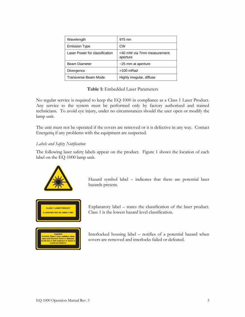
Wavelength 975 nm
Emission Type CW
Laser Power for classification <40 mW via 7mm measurement aperture
Beam Diameter ~25 mm at aperture
Divergence >100 mRad
Transverse Beam Mode Highly irregular, diffuse
Table 1: Embedded Laser Parameters
No regular service is required to keep the EQ-1000 in compliance as a Class 1 Laser Product. Any service to the system must be performed only by factory authorized and trained technicians. To avoid eye injury, under no circumstances should the user open or modify the lamp unit.
The unit must not be operated if the covers are removed or it is defective in any way. Contact Energetiq if any problems with the equipment are suspected.
Labels and Safety Notification
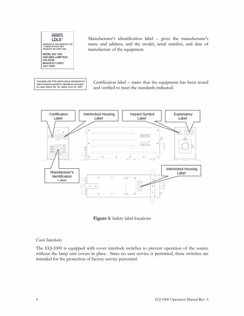
The following laser safety labels appear on the product. Figure 1 shows the location of each label on the EQ-1000 lamp unit.
Hazard symbol label – indicates that there are potential laser hazards present.
Explanatory label – states the classification of the laser product. Class 1 is the lowest hazard level classification.
Interlocked housing label – notifies of a potential hazard when covers are removed and interlocks failed or defeated.
4 EQ-1000 Operation Manual Rev. 5
Manufacturer’s identification label – gives the manufacturer’s name and address, and the model, serial number, and date of manufacture of the equipment.
Certification label – states that the equipment has been tested and verified to meet the standards indicated.
Figure 1: Safety label locations
Cover Interlocks
The EQ-1000 is equipped with cover interlock switches to prevent operation of the source without the lamp unit covers in place. Since no user service is permitted, these switches are intended for the protection of factory service personnel.
J1
LAMP ON
N2 INLET20PSIG
WATER OUTU.S. PATENT #7,435,982
100 PSIG MAXWATER IN
N2 RELIEF
OTHER PATENTS PENDING
Manufacturer’s Identification
Label
Certification Label
Explanatory Label
Hazard Symbol Label
Interlocked Housing Label
Interlocked Housing Label
EQ-1000 Operation Manual Rev. 5 5
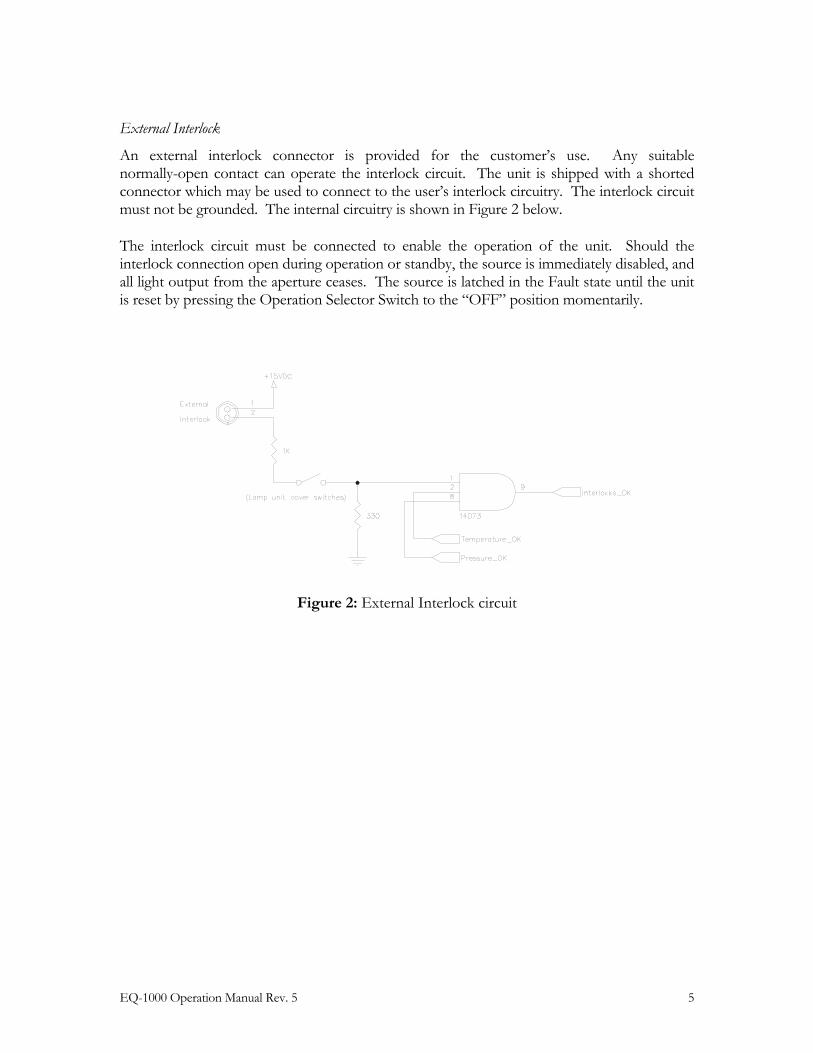
External Interlock
An external interlock connector is provided for the customer’s use. Any suitable normally-open contact can operate the interlock circuit. The unit is shipped with a shorted connector which may be used to connect to the user’s interlock circuitry. The interlock circuit must not be grounded. The internal circuitry is shown in Figure 2 below.
The interlock circuit must be connected to enable the operation of the unit. Should the interlock connection open during operation or standby, the source is immediately disabled, and all light output from the aperture ceases. The source is latched in the Fault state until the unit is reset by pressing the Operation Selector Switch to the “OFF” position momentarily.
Figure 2: External Interlock circuit

6 EQ-1000 Operation Manual Rev. 5
EQ-1000 Operation Manual Rev. 5 7
C h a p t e r 2
DESCRIPTION
General
The EQ-1000 is a DUV lamp system for use in laboratory or test applications. The lamp features high brightness, broad-band light from DUV wavelengths through visible and beyond. The output is very stable, and has a long lifetime before any service is required. The interface is quite simple, but robust enough for any lab or industrial environment.
The EQ-1000 system consists of a power supply unit, lamp unit, and interconnecting cable. Connections to AC power, cooling water, and purge gas are required for operation.
Specifications
DUV Performance
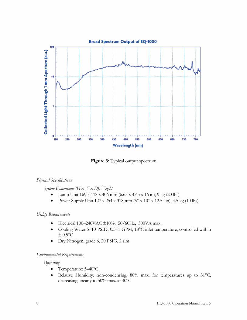
• Power Output >0.03 mW/nm collected through a 1mm aperture from 180nm to 800nm into 0.22NA
• Power Output >0.75 mW/nm collected through a 5mm aperture from 180nm to 800nm into 0.22NA
• Typical output spectrum: see Figure 3.
8 EQ-1000 Operation Manual Rev. 5
Figure 3: Typical output spectrum
Physical Specifications
System Dimensions (H x W x D), Weight • Lamp Unit 169 x 118 x 406 mm (6.65 x 4.65 x 16 in), 9 kg (20 lbs) • Power Supply Unit 127 x 254 x 318 mm (5” x 10” x 12.5” in), 4.5 kg (10 lbs)
Utility Requirements
• Electrical 100–240VAC ±10%, 50/60Hz, 300VA max. • Cooling Water 5–10 PSID, 0.5–1 GPM, 18°C inlet temperature, controlled within
± 0.5°C • Dry Nitrogen, grade 6, 20 PSIG, 2 slm
Environmental Requirements
Operating • Temperature: 5–40°C • Relative Humidity: non-condensing, 80% max. for temperatures up to 31°C,
decreasing linearly to 50% max. at 40°C
EQ-1000 Operation Manual Rev. 5 9
• Altitude: 2000 m (6562 ft) max. • Pollution Degree 2 (normally only non-conductive pollution; occasional,
temporary condensation possible) • Installation Category: Indoor use only
Transport • Temperature: -5–95°C • Relative Humidity: non-condensing, 95% max.
Identification of Controls
The following sections show the location of controls and other features, and give an overview of their functions. Refer to the “Installation” section of this manual (Chapter 3) for more detailed information.
Power Supply Unit
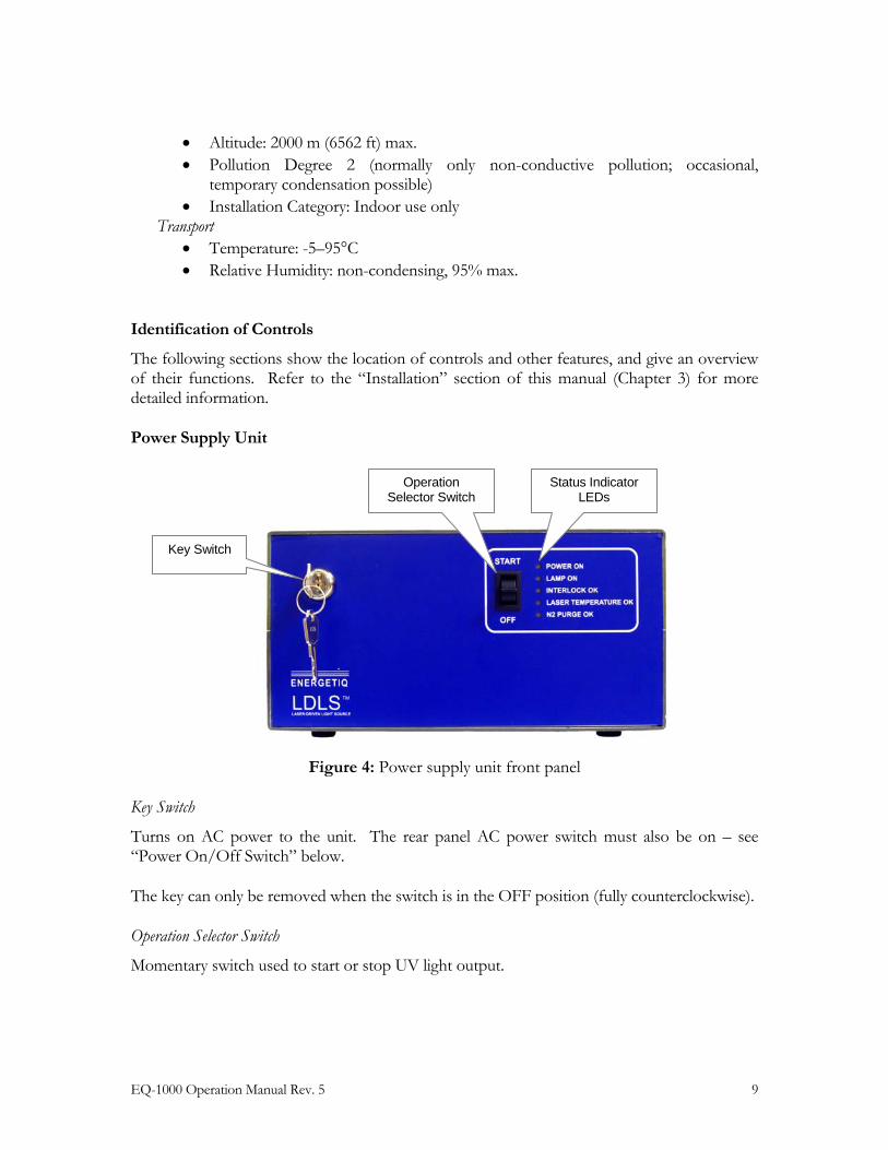
Figure 4: Power supply unit front panel
Key Switch
Turns on AC power to the unit. The rear panel AC power switch must also be on – see “Power On/Off Switch” below.
The key can only be removed when the switch is in the OFF position (fully counterclockwise).
Operation Selector Switch
Momentary switch used to start or stop UV light output.
Key Switch
Operation Selector Switch
Status Indicator LEDs
10 EQ-1000 Operation Manual Rev. 5
Status Indicator LEDs
These five LEDs indicate the system status. The function of these indicators is shown below in Table 2.
LED Label Meaning (when lit)
POWER ON AC power to the EQ-1000 is on
LAMP ON UV Light is on
INTERLOCK OK All interlocks are satisfied (external interlock, cover switches, laser temperature, and N2 pressure)
LASER TEMPERATURE OK Laser temperature in lamp unit is within limits
N2 PURGE OK Pressure of nitrogen gas purge is within limits
Table 2: Front Panel LED functions
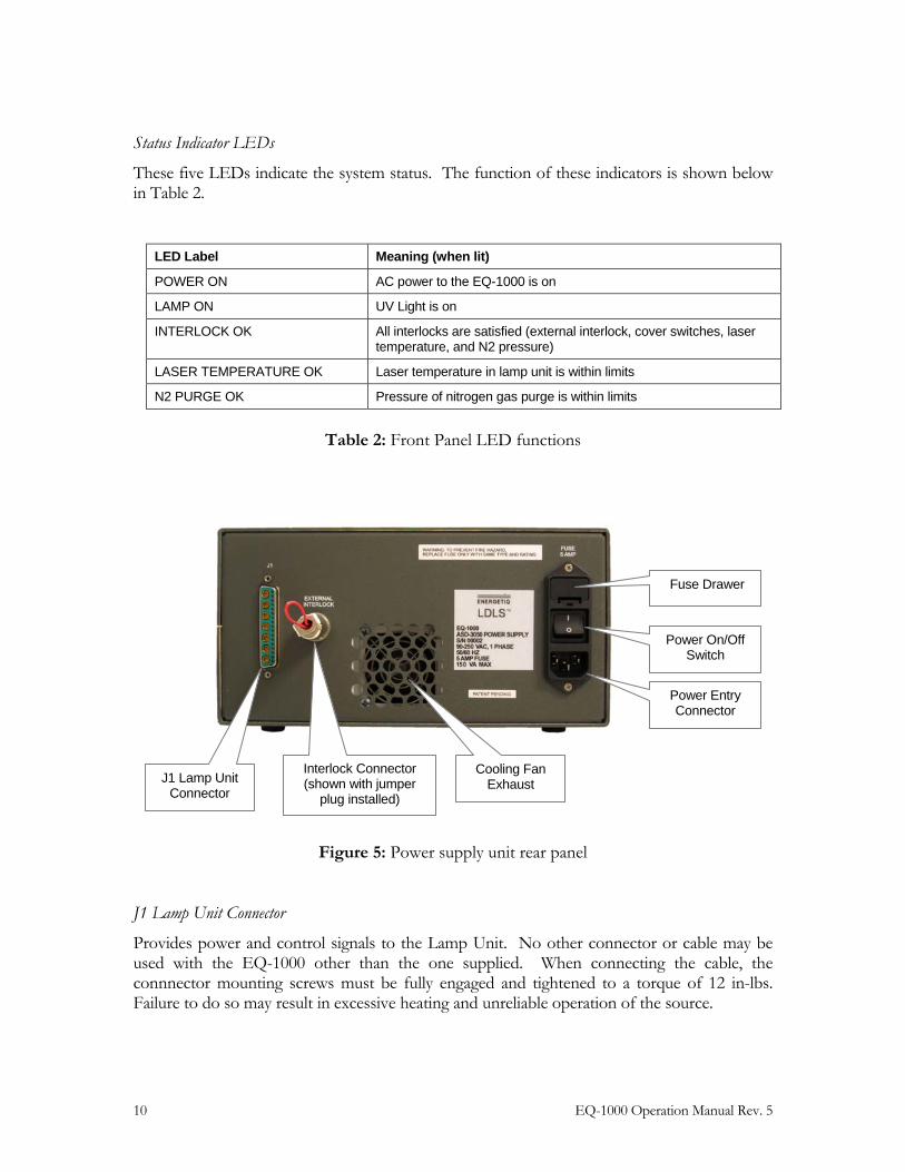
Figure 5: Power supply unit rear panel
J1 Lamp Unit Connector
Provides power and control signals to the Lamp Unit. No other connector or cable may be used with the EQ-1000 other than the one supplied. When connecting the cable, the connnector mounting screws must be fully engaged and tightened to a torque of 12 in-lbs. Failure to do so may result in excessive heating and unreliable operation of the source.
Interlock Connector (shown with jumper
plug installed) J1 Lamp Unit
Connector
Power Entry Connector
Power On/Off Switch
Fuse Drawer
Cooling Fan Exhaust
EQ-1000 Operation Manual Rev. 5 11
Interlock Connector
Provides connection to the safety interlock circuit. We recommend that any door or enclosure switches used in the user’s system be added in series with this interlock connection.
Power Entry Connector
The power input connection to the EQ-1000 is made via a standard IEC 3-pin power entry module. A power cable is included with the system, but any standard cable can be used.
Fuse Drawer
Two AC line fuses are installed in this fuse holder. The value of these fuses must be correctly selected based on the line voltage being used. Refer to the Installation section in the next chapter for instructions on correct voltage and fuse combinations, and fuse replacement.
Power On/Off Switch
This switch is used as a main AC power switch. It can also be used as an emergency off switch. Note that the EQ-1000 does not power up until both this switch and the front-panel key switch are turned on.
Cooling Fan Exhaust
The internal laser power supply is air cooled. To avoid overheating, do not obstruct this fan exhaust.
12 EQ-1000 Operation Manual Rev. 5
Lamp Unit
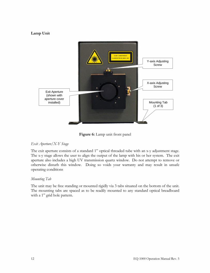
Figure 6: Lamp unit front panel
Exit Aperture/X-Y Stage
The exit aperture consists of a standard 1” optical threaded tube with an x-y adjustment stage. The x-y stage allows the user to align the output of the lamp with his or her system. The exit aperture also includes a high UV transmission quartz window. Do not attempt to remove or otherwise disturb this window. Doing so voids your warranty and may result in unsafe operating conditions
Mounting Tab
The unit may be free standing or mounted rigidly via 3 tabs situated on the bottom of the unit. The mounting tabs are spaced as to be readily mounted to any standard optical breadboard with a 1” grid hole pattern.
Exit Aperture (shown with
aperture cover installed)
X-axis Adjusting Screw
Y-axis Adjusting Screw
Mounting Tab (1 of 3)
EQ-1000 Operation Manual Rev. 5 13
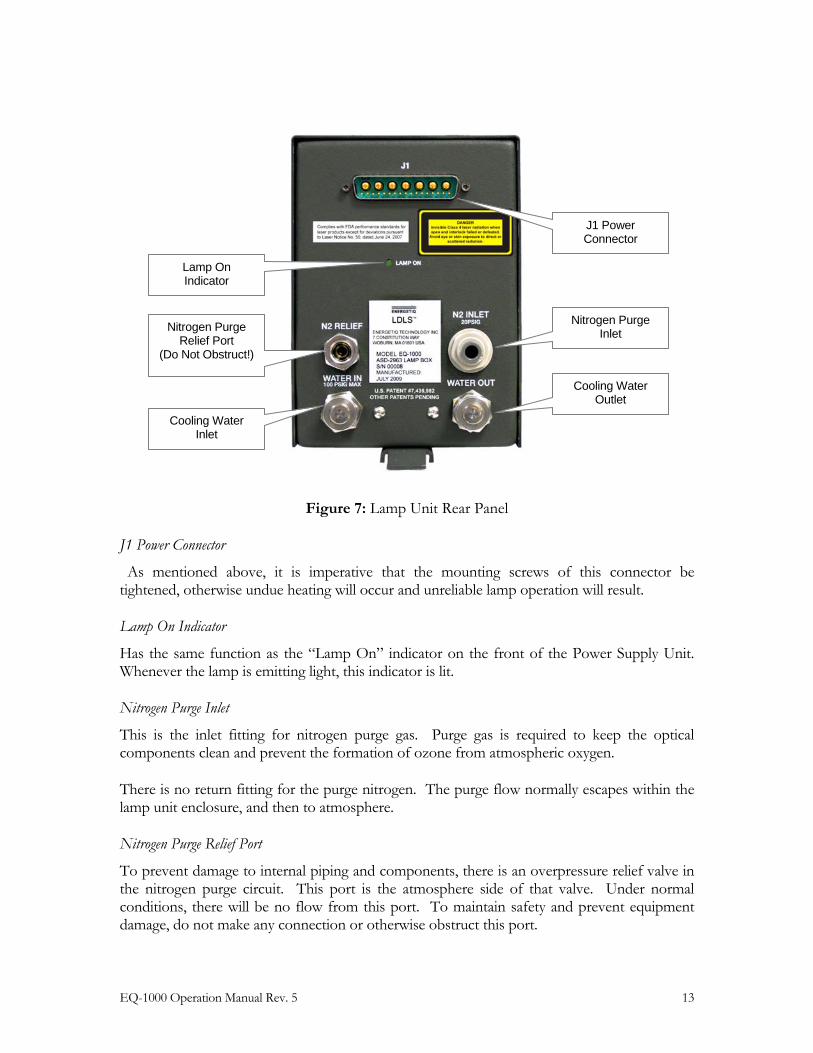
Figure 7: Lamp Unit Rear Panel
J1 Power Connector
As mentioned above, it is imperative that the mounting screws of this connector be tightened, otherwise undue heating will occur and unreliable lamp operation will result.
Lamp On Indicator
Has the same function as the “Lamp On” indicator on the front of the Power Supply Unit. Whenever the lamp is emitting light, this indicator is lit.
Nitrogen Purge Inlet
This is the inlet fitting for nitrogen purge gas. Purge gas is required to keep the optical components clean and prevent the formation of ozone from atmospheric oxygen.
There is no return fitting for the purge nitrogen. The purge flow normally escapes within the lamp unit enclosure, and then to atmosphere.
Nitrogen Purge Relief Port
To prevent damage to internal piping and components, there is an overpressure relief valve in the nitrogen purge circuit. This port is the atmosphere side of that valve. Under normal conditions, there will be no flow from this port. To maintain safety and prevent equipment damage, do not make any connection or otherwise obstruct this port.
Nitrogen Purge Inlet
J1 Power Connector
Cooling Water Outlet
Lamp On Indicator
Nitrogen Purge Relief Port
(Do Not Obstruct!)
Cooling Water Inlet
14 EQ-1000 Operation Manual Rev. 5
Cooling Water Inlet/Outlet
These are the connection points for cooling water used to cool the internal drive laser.
EQ-1000 Operation Manual Rev. 5 15
C h a p t e r 3
INSTALLATION
Installation of the EQ-1000 consists of connecting electrical, water, and gas supplies, and connecting the lamp output to the user’s equimpent.
Facilities Requirements
Electrical Service
The EQ-1000 is a universal input voltage device, and can be operated from 100VAC to 240VAC, single-phase, 50-60Hz. Power consumption is approximately 200VA during normal operation, 300VA during lamp starting.
The EQ-1000 uses a detachable three-wire standard IEC 60320 C13 cord for connection to the power source. The cord also provides the connection to the protective earth circuit. Exposed metal parts of the EQ-1000 are connected to the protective earth ground via the cord and the outlet ground, providing protection against electrical shock. Never operate the EQ-1000 from an outlet without a properly connected protective earth ground.
There is no selection switch for line voltage, it is automatically adjusted internally.
Line Fuse
The unit is shipped with 5A fuses installed for 100-120VAC input. For use at 220-240 VAC, the line fuses must be changed to 2.5 A.
In order to change the fuses, disconnect the power cord and open the fuse drawer by depressing the latch below the drawer. Slide out the drawer and replace the two fuses. The fuses are held in metal clips in the drawer. Replace the fuse drawer in the input connector; it is polarized and can only be installed in one orientation. The fuse drawer is properly seated when the edge is flush with the input connector body.
The fuses for 100-120VAC operation are 5A, 250V, 5x20mm, fast-acting fuses. Fuses for 220-240VAC operation are 2.5A, 250V, 5x20mm, fast-acting fuses. Consult factory if there are any questions regarding fuse selection.
Cooling Water
The EQ-1000 requires 0.5–1gpm water at a minimum of 20psi. The temperature must be held at 18 +/- 0.5 degrees C. The pressure drop at 1gpm through the cold plate is less than 10psi. There are several thermoelectric and direct water-to-water chillers that can satisfy these requirements. Tight temperature regulation is required for tight regulation in the lamp’s
16 EQ-1000 Operation Manual Rev. 5
output. If there are any questions or concerns, please contact the manufacturer for recommendations or guidance.
The water connection fittings are standard 3/8” Swagelok® connectors. Do not attempt to use other non-Swagelok connectors, as they will not seal properly and will likely damage the unit.
Purge Gas
The EQ-1000 requires grade 6 or better Nitrogen purge gas. The requirement for purge gas is a result of the EQ-1000 lamp’s unique performance and operating principles. The EQ-1000 produces UV radiation capable of generating ozone gas when exposed to atmospheric Oxygen. So first and foremost, the Nitrogen purge gas is intended to displace any Oxygen in the system’s optical chamber. The optics assembly is in direct contact with this purge gas. UV optics are quite prone to UV photocontamination. Clean and pure Nitrogen from either a dewar or research-grade N2 bottle is recommended. Do not use any other purge gas. Usage of compressed dry air (CDA) will destroy the optical chamber and likely produce Ozone gas, which is a potential inhalation hazard.
The fitting is a push-to-connect gas fitting sized for 1/4” O.D. tubing. The suggested hose to mate to this fitting is either Nylon: Shore D 50-70, Polyethylene: Shore D 50-196, or Teflon 1/4” O.D. tubing.
There is no return fitting for the purge nitrogen. The purge flow normally escapes within the lamp unit enclosure, and then to atmosphere.
Optical Interface
The exit aperture consists of a standard 1” optical threaded tube with an x-y adjustment stage. The x-y stage allows the user to align the output of the lamp with his or her system. The barrel is made of nickel plated aluminum to minimize photocontamination at the short wavelengths exiting the lamp aperture. It is suggested that the user consider similar materials for his or her beamline to minimize the risk of photocontamination of optical surfaces.
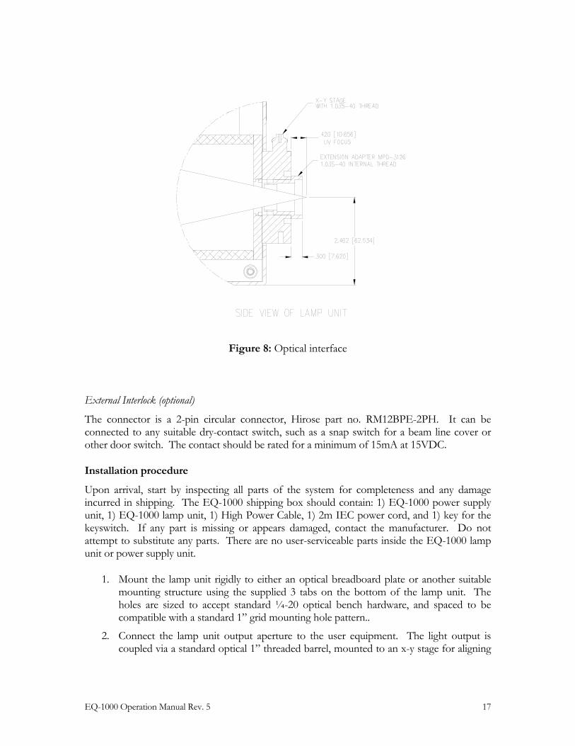
The nominal focus of the output is 0.4” past the quartz output window inside the threaded barrel. The user may want to place an aperture or other optic at or near this interface point. The optical tube makes this very simple. Figure 8 shows the details of the optical interface.
Any beam transport space should be purged with dry Nitrogen to prevent the formation of ozone from atmospheric oxygen.
EQ-1000 Operation Manual Rev. 5 17
Figure 8: Optical interface
External Interlock (optional)
The connector is a 2-pin circular connector, Hirose part no. RM12BPE-2PH. It can be connected to any suitable dry-contact switch, such as a snap switch for a beam line cover or other door switch. The contact should be rated for a minimum of 15mA at 15VDC.
Installation procedure
Upon arrival, start by inspecting all parts of the system for completeness and any damage incurred in shipping. The EQ-1000 shipping box should contain: 1) EQ-1000 power supply unit, 1) EQ-1000 lamp unit, 1) High Power Cable, 1) 2m IEC power cord, and 1) key for the keyswitch. If any part is missing or appears damaged, contact the manufacturer. Do not attempt to substitute any parts. There are no user-serviceable parts inside the EQ-1000 lamp unit or power supply unit.
1. Mount the lamp unit rigidly to either an optical breadboard plate or another suitable mounting structure using the supplied 3 tabs on the bottom of the lamp unit. The holes are sized to accept standard ¼-20 optical bench hardware, and spaced to be compatible with a standard 1” grid mounting hole pattern..
2. Connect the lamp unit output aperture to the user equipment. The light output is coupled via a standard optical 1” threaded barrel, mounted to an x-y stage for aligning
18 EQ-1000 Operation Manual Rev. 5
the EQ-1000 output beam with any external detector, target, or fiber coupler. The beam should always be either directly coupled to a fiber optic cable, or enclosed in an appropriate beam pipe, tube, or enclosed space and purged with Nitrogen. Operating the source without any output target or beam transport is not recommended, and may lead to unsafe operating conditions. Consult Energetiq for applications information and suggested configurations.
3. Setup the lamp unit with appropriate ultraviolet safety measures and laser light safety measures in place. It is recommended that any enclosure or aperture-blocking hardware utilize doors switches wired to the EQ-1000 external interlock circuit.
4. Place the power supply unit no farther than 6 feet from the lamp unit, as the supplied High Power Cable is only 2 meters long. Do not block the air vents at the rear or sides of the lamp power supply unit.
5. Connect the supplied High Power Cable to the lamp unit and the power supply unit. The connectors are polarized to prevent errors in setup. Be sure to screw the attached flathead connector mounting screws fully with 12 in-lbs torque. Failure to do so will result in undue heating in the connector body and unreliable lamp operation.
6. Connect the lamp unit to cooling water and Nitrogen purge gas. Refer to “Facilities Requirements” above.
7. Verify that both the main power switch on the back of the lamp power supply and the key switch on the front of the power supply unit are in the “OFF” position.
8. Verify that the correct line fuses are installed (see “Facilities Requirements” above). Connect the supplied IEC cord to the lamp power supply unit and to the power source.
9. Purge the EQ-1000 unit for at least 10 minutes prior to operation. Failure to purge the system properly will permanently damage the optics and may produce ozone gas.
10. Verify that cooling water is flowing and the temperature is at maximum 18 degrees C. Operation of the EQ-1000 lamp at a higher temperature will result in reduced performance and possibly shorter lamp life.
The system is now ready to operate.
EQ-1000 Operation Manual Rev. 5 19
C h a p t e r 4
OPERATION
Starting
Once the lamp is set up properly, verify that all personnel that will be in contact with the lamp unit are aware of the potential hazards involved with the lamp. It is up to the user to verify that the lamp is being used safely.
The lamp is quite easy to operate. Begin by turning on the main power switch on the back of the unit. Verify that all safety measures are in place. Turn the key switch to the “ON” position. The lamp front panel lights should indicate power and the interlock status. If the interlocks are all satisfied, and the lamp is purged properly, you may push the Operation Selector Switch momentarily up to the “START” position. The EQ-1000 enters the start mode. While in the start mode, the lamp unit will click a few times, then the “LIGHT ON” indicator will come on. When the lamp is started, UV radiation is present at the exit aperture and the “LIGHT ON” indicator at the back of the lamp unit will also be lit. During this time, the lamp is in running mode.
If the lamp does not start within approximately 16 seconds, start mode will terminate (i.e., the lamp stops trying to ignite). If this happens, just push the Operation Selector Switch to “START” to try again. If the lamp still does not ignite after 1 or 2 more attempts, raise the cooling water temperature to 25°C and try again. Once the lamp ignites, lower the temperature setpoint back to 18°C for normal operation.
For optimal results, the EQ-1000 should be allowed to complete a warmup period of 5 minutes. During this time the lamp output is stabilizing. The lamp may be operated after the warmup period for any length of time the user needs; continuous or short-period operation are both acceptable.
Stopping
When the user is finished using the lamp, he or she should simply push the Operation Selector Switch down momentarily to the “OFF” position. It is also possible to stop the lamp by opening the interlock chain or turning off the key switch. Opening the interlock chain will place the lamp into a Fault state, and the lamp is latched in this state until the Operation Selector Switch is reset by pushing the lever in the down “OFF” direction.

20 EQ-1000 Operation Manual Rev. 5
EQ-1000 Operation Manual Rev. 5 21
C h a p t e r 5
TROUBLESHOOTING
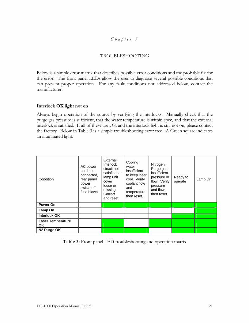
Below is a simple error matrix that describes possible error conditions and the probable fix for the error. The front panel LEDs allow the user to diagnose several possible conditions that can prevent proper operation. For any fault conditions not addressed below, contact the manufacturer.
Interlock OK light not on
Always begin operation of the source by verifying the interlocks. Manually check that the purge gas pressure is sufficient, that the water temperature is within spec, and that the external interlock is satisfied. If all of these are OK and the interlock light is still not on, please contact the factory. Below in Table 3 is a simple troubleshooting error tree. A Green square indicates an illuminated light.
Condition
AC power cord not connected, rear panel power switch off, fuse blown.
External Interlock circuit not satisfied, or lamp unit cover loose or missing. Correct and reset.
Cooling water insufficient to keep laser cool. Verify coolant flow and temperature, then reset.
Nitrogen Purge gas insufficient pressure or flow. Verify pressure and flow then reset.
Ready to operate Lamp On
Power On Lamp On Interlock OK Laser Temperature OK
N2 Purge OK
Table 3: Front panel LED troubleshooting and operation matrix

22 EQ-1000 Operation Manual Rev. 5

EQ-1000 Operation Manual Rev. 5 23

Copyright © 2009 Energetiq Technology Inc. All rights reserved.
Energetiq products are covered by US and foreign patents. All technical information, including drawings, schematics and specifications contained in this manual are the property of Energetiq and shall not be reproduced in whole or in part without the written consent of Energetiq. The content of this manual is subject to change without notice.
Energetiq Technology Inc. 7 Constitution Way, Woburn, MA 01801 USA Tel. +1 (781) 939-0763 Fax +1 (781) 939-0769 E-mail: [email protected] http://www.energetiq.com


![Chapter 6 - Chromedia · Chapter 6 Equilibrium Chemistry 213 K cd ab = [] [] CD AB eq eq eq eq 6.5 Here we include the subscript “eq” to indicate a concentration at equilib‑](https://img.pdfslide.us/doc/110x75/5f39c80721ac1114a433e66d/chapter-6-chromedia-chapter-6-equilibrium-chemistry-213-k-cd-ab-cd-ab.jpg)