Embed Size (px)
Citation preview
O P E R AT I N G I N S T R U C T I O N S
People counting made easy
LD-PeCoPeople Counter
Operating Instructions
LD-PeCo People Counter
2 © SICK AG · Division Auto Ident · Germany · All rights reserved 8010332/QH23/2007-02-05
Software Versions
Software Versions
CopyrightCopyright © 2007SICK AG WaldkirchAuto Ident, Reute PlantNimburger Strasse 1179276 ReuteGermany
TrademarksWindows 95/98TM, Windows NT4.0TM, Windows 2000TM and Windows XPTM are registered trademarks of the Microsoft Corporation in the USA and other countries.
Latest Manual VersionFor the latest version of this manual (PDF), see www.sick.com.
Software/Tool Function Version
LD-PeCo Firmware V 36-030704_R
PeCo Setup Configuration software V 1.0.0
Operating Instructions
LD-PeCo
8010332/QH23/2007-02-05 © SICK AG · Division Auto Ident · Germany · All rights reserved 3
Quick Finder
LD-PeCo People Counter
Quick Finder
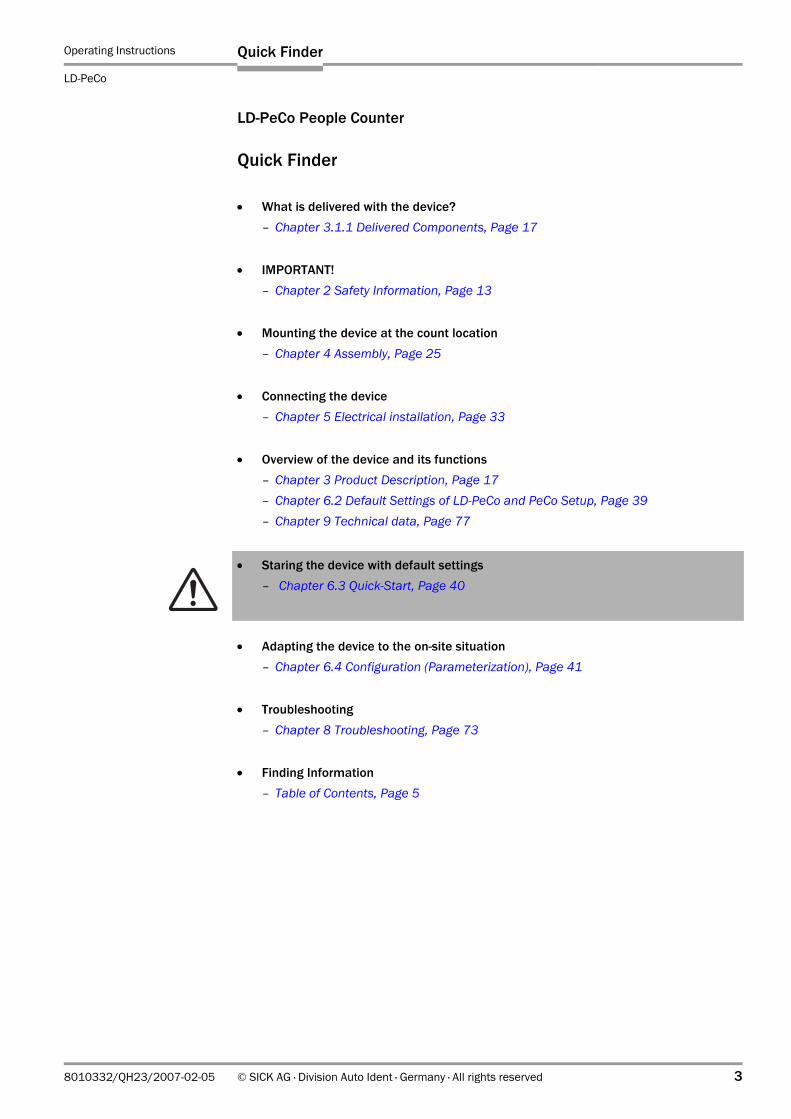
• What is delivered with the device?– Chapter 3.1.1 Delivered Components, Page 17
• IMPORTANT!– Chapter 2 Safety Information, Page 13
• Mounting the device at the count location– Chapter 4 Assembly, Page 25
• Connecting the device– Chapter 5 Electrical installation, Page 33
• Overview of the device and its functions– Chapter 3 Product Description, Page 17– Chapter 6.2 Default Settings of LD-PeCo and PeCo Setup, Page 39– Chapter 9 Technical data, Page 77
• Staring the device with default settings– Chapter 6.3 Quick-Start, Page 40
• Adapting the device to the on-site situation– Chapter 6.4 Configuration (Parameterization), Page 41
• Troubleshooting– Chapter 8 Troubleshooting, Page 73
• Finding Information– Table of Contents, Page 5
Operating Instructions
LD-PeCo People Counter
Quick Finder
4 © SICK AG · Division Auto Ident · Germany · All rights reserved 8010332/QH23/2007-02-05
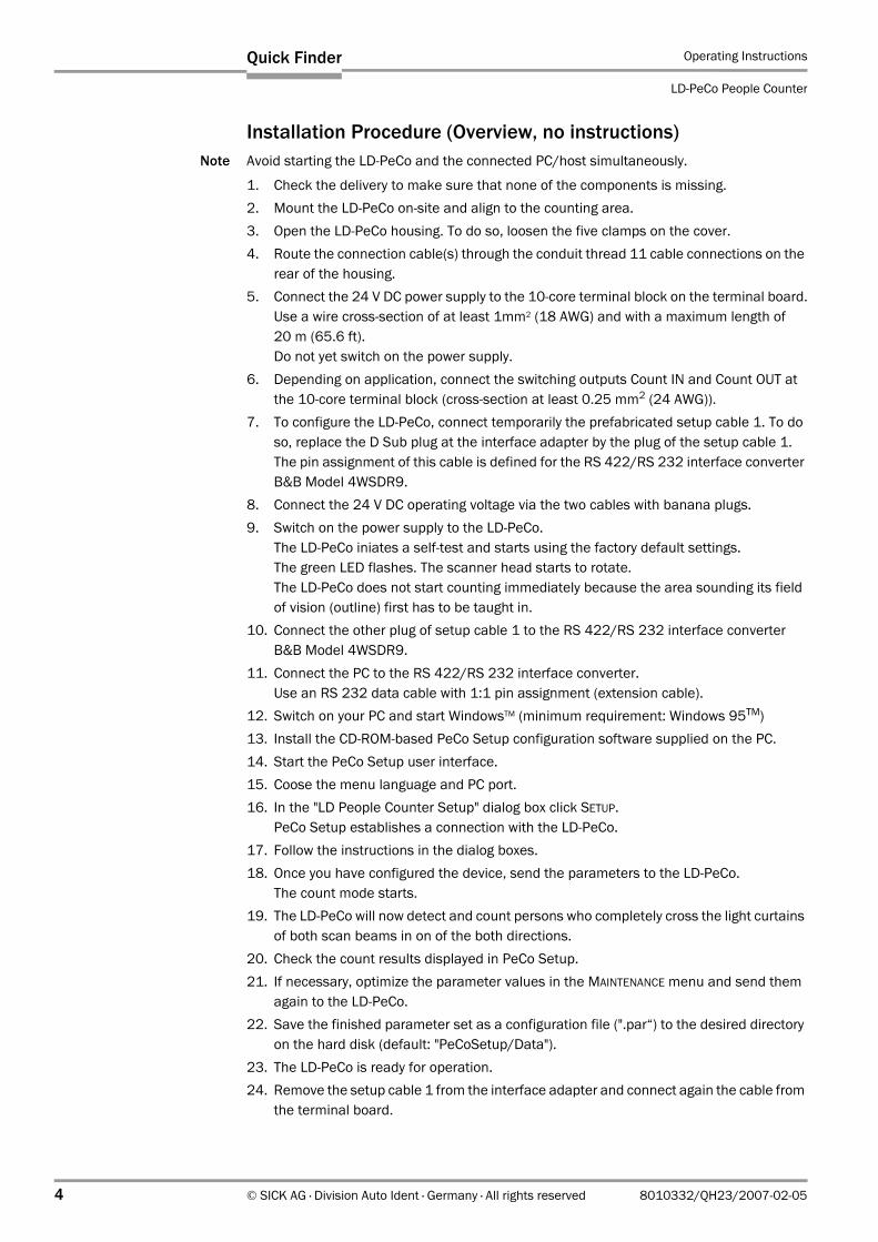
Installation Procedure (Overview, no instructions)Note Avoid starting the LD-PeCo and the connected PC/host simultaneously.
1. Check the delivery to make sure that none of the components is missing.2. Mount the LD-PeCo on-site and align to the counting area. 3. Open the LD-PeCo housing. To do so, loosen the five clamps on the cover.4. Route the connection cable(s) through the conduit thread 11 cable connections on the
rear of the housing.5. Connect the 24 V DC power supply to the 10-core terminal block on the terminal board.
Use a wire cross-section of at least 1mm2 (18 AWG) and with a maximum length of 20 m (65.6 ft). Do not yet switch on the power supply.
6. Depending on application, connect the switching outputs Count IN and Count OUT at the 10-core terminal block (cross-section at least 0.25 mm2 (24 AWG)).
7. To configure the LD-PeCo, connect temporarily the prefabricated setup cable 1. To do so, replace the D Sub plug at the interface adapter by the plug of the setup cable 1.The pin assignment of this cable is defined for the RS 422/RS 232 interface converter B&B Model 4WSDR9.
8. Connect the 24 V DC operating voltage via the two cables with banana plugs.9. Switch on the power supply to the LD-PeCo.
The LD-PeCo iniates a self-test and starts using the factory default settings. The green LED flashes. The scanner head starts to rotate. The LD-PeCo does not start counting immediately because the area sounding its field of vision (outline) first has to be taught in.
10. Connect the other plug of setup cable 1 to the RS 422/RS 232 interface converter B&B Model 4WSDR9.
11. Connect the PC to the RS 422/RS 232 interface converter.Use an RS 232 data cable with 1:1 pin assignment (extension cable).
12. Switch on your PC and start WindowsTM (minimum requirement: Windows 95TM)13. Install the CD-ROM-based PeCo Setup configuration software supplied on the PC.14. Start the PeCo Setup user interface.15. Coose the menu language and PC port.16. In the "LD People Counter Setup" dialog box click SETUP.
PeCo Setup establishes a connection with the LD-PeCo.17. Follow the instructions in the dialog boxes. 18. Once you have configured the device, send the parameters to the LD-PeCo.
The count mode starts.19. The LD-PeCo will now detect and count persons who completely cross the light curtains
of both scan beams in on of the both directions.20. Check the count results displayed in PeCo Setup.21. If necessary, optimize the parameter values in the MAINTENANCE menu and send them
again to the LD-PeCo.22. Save the finished parameter set as a configuration file (".par“) to the desired directory
on the hard disk (default: "PeCoSetup/Data").23. The LD-PeCo is ready for operation.24. Remove the setup cable 1 from the interface adapter and connect again the cable from
the terminal board.
Operating Instructions
LD-PeCo
Contents
8010332/QH23/2007-02-05 © SICK AG · Division Auto Ident · Germany · All rights reserved 5
Contents1 Notes On This Document .........................................................................................111.1 Function..................................................................................................................111.2 Target audience .....................................................................................................11
1.2.1 Assembly, Electrical Installation, Maintenance, and Replacement..............111.2.2 Commissioning, Operation, and Configuration ..............................................11
1.3 Information Content...............................................................................................111.4 Symbols Used.........................................................................................................122 Safety Information ....................................................................................................132.1 Safety Standards ...................................................................................................132.2 Authorized users ....................................................................................................13
2.2.1 Assembly and Maintenance ............................................................................132.2.2 Electrical Installation and Device Replacement ............................................132.2.3 Commissioning, Operation, and Configuration ..............................................132.2.4 Processing Measured Values in IT Systems...................................................13
2.3 Intended Use ..........................................................................................................132.4 Operating Reliability...............................................................................................142.5 General Safety Information and Protection Measures........................................14
2.5.1 Correct Use .......................................................................................................142.5.2 Electrical Installation........................................................................................142.5.3 Laser Safety......................................................................................................15
2.6 Quick Stop and Quick Restart ...............................................................................162.6.1 Switching off the LD-PeCo ...............................................................................162.6.2 Switching the LD-PeCo On Again.....................................................................16
2.7 Environmental informations..................................................................................162.7.1 Power Consumption .........................................................................................162.7.2 Disposal After Removal from Service .............................................................16
3 Product Description ..................................................................................................173.1 Device Structure ....................................................................................................17
3.1.1 Delivered Components ....................................................................................173.1.2 Device Variants.................................................................................................173.1.3 System Requirements......................................................................................173.1.4 Product Features and Functions (Overview) ..................................................183.1.5 Applications ......................................................................................................193.1.6 Device View.......................................................................................................20
3.2 Operating Principle ................................................................................................213.2.1 Switching outputs.............................................................................................223.2.2 Data Interface...................................................................................................23
3.3 Displays and Controls ............................................................................................233.3.1 Controls.............................................................................................................233.3.2 Function of the LEDs........................................................................................23
4 Assembly ....................................................................................................................254.1 Overview of the Assembly Steps...........................................................................254.2 Preparations for Installation..................................................................................25
4.2.1 Ensure that you have all the required components.......................................254.2.2 Preparing the Accessories ...............................................................................254.2.3 Auxiliary Parts ...................................................................................................254.2.4 Selecting the Mounting Location ....................................................................254.2.5 Mounting Accessories......................................................................................254.2.6 Distance Between the LD-PeCo and Flow of Persons ...................................264.2.7 Installing Two LD-PeCo Systems .....................................................................274.2.8 Controlling the Flow of Persons.......................................................................274.2.9 Installation in Front of Doors...........................................................................284.2.10 Accessories: LS-70B Scanfinder (Laser Detector) .........................................29
4.3 Mounting and Adjusting the Device......................................................................304.3.1 Mounting the LD-PeCo .....................................................................................304.3.2 Coordinate System and Angles of Rotation....................................................30
Operating Instructions
LD-PeCo People Counter
6 © SICK AG · Division Auto Ident · Germany · All rights reserved 8010332/QH23/2007-02-05
Contents
4.3.3 Aligning the LD-PeCo ....................................................................................... 314.3.4 Install the Safety Cord ..................................................................................... 31
4.4 Disassembling the Device .................................................................................... 324.4.1 Storage ............................................................................................................. 324.4.2 Disposal............................................................................................................ 32
5 Electrical installation................................................................................................ 335.1 Installation Steps................................................................................................... 335.2 Electrical Connections and Cables....................................................................... 33
5.2.1 LD-PeCo Terminal Board ................................................................................. 335.2.2 Connection Principle........................................................................................ 345.2.3 Core Cross-Sections......................................................................................... 345.2.4 Prefabricated Cables ....................................................................................... 34
5.3 Pin Assignment of the Connections ..................................................................... 355.3.1 Electrical Connections (10-core Terminal Block)........................................... 35
5.4 Preparations for Electrical Installation................................................................. 355.4.1 Conditions for the Data Interface ................................................................... 355.4.2 Power Supply.................................................................................................... 35
5.5 Carrying Out Electrical Installation ....................................................................... 365.5.1 Tools ................................................................................................................. 365.5.2 Connecting the Power Supply ......................................................................... 365.5.3 Connecting the Switching Outputs ................................................................. 375.5.4 Connecting the PC ........................................................................................... 375.5.5 Connecting the Host ........................................................................................ 38
6 Operation ................................................................................................................... 396.1 Commissioning Overview ...................................................................................... 396.2 Default Settings of LD-PeCo and PeCo Setup ..................................................... 396.3 Quick-Start ............................................................................................................. 40
6.3.1 Starting Up LD-PeCo with the Default Factory Settings ................................ 406.4 Configuration (Parameterization) ......................................................................... 41
6.4.1 Configuring LD-PeCo with the PeCo Setup User Interface ............................ 416.4.2 Installing the PeCo Setup Software ................................................................ 416.4.3 Software Functions (Overview) ....................................................................... 426.4.4 Overview of Configuration Steps..................................................................... 426.4.5 "PeCo Setup" User Interface ........................................................................... 426.4.6 "Program Settings" Dialog Box ........................................................................ 436.4.7 "LD People Counter Setup" Dialog Box........................................................... 43
6.5 Setup ...................................................................................................................... 446.5.1 "Options for Setup" Dialog Box........................................................................ 446.5.2 "Step 1“ Dialog Box.......................................................................................... 456.5.3 "Step 2" Dialog Box.......................................................................................... 466.5.4 "Step 3" Dialog Box.......................................................................................... 476.5.5 "Step 4" Dialog Box.......................................................................................... 506.5.6 "Step 5" Dialog Box.......................................................................................... 526.5.7 "Step 6" Dialog Box.......................................................................................... 54
6.6 Maintenance.......................................................................................................... 576.6.1 "Scanner" Tab................................................................................................... 576.6.2 "Scans/Segments“ Tab ................................................................................... 586.6.3 "Borders" Tab ................................................................................................... 616.6.4 "Objects" Tab.................................................................................................... 626.6.5 "Commands" Tab ............................................................................................. 63
6.7 Counter Reading.................................................................................................... 666.7.1 De-Installing the "PeCo Setup" Software........................................................ 67
6.8 Switching Off the LD-PeCo .................................................................................... 687 Maintenance.............................................................................................................. 697.1 Maintenance During Operation ............................................................................ 697.2 Maintenance.......................................................................................................... 707.3 Disposal ................................................................................................................. 71
Operating Instructions
LD-PeCo
Contents
8010332/QH23/2007-02-05 © SICK AG · Division Auto Ident · Germany · All rights reserved 7
8 Troubleshooting.........................................................................................................738.1 Overview of Possible Errors and Malfunctions ....................................................73
8.1.1 Mounting Errors................................................................................................738.1.2 Electrical Installation Errors.............................................................................738.1.3 Parameterization Errors...................................................................................738.1.4 Operational Malfunctions ................................................................................73
8.2 Monitoring Error and Fault Signs ..........................................................................738.3 Troubleshooting .....................................................................................................738.4 SICK Support ..........................................................................................................769 Technical data ...........................................................................................................779.1 Variant Overview ....................................................................................................779.2 Data Sheet LD-PeCo People Counter ...................................................................779.3 Dimensioned Drawing ...........................................................................................7810 Appendix.....................................................................................................................7910.1 Overview of Appendix ............................................................................................7910.2 Available Accessories ............................................................................................80
10.2.1 Mounting accessories......................................................................................8010.2.2 Cables ...............................................................................................................8010.2.3 LS-70B Scanfinder (Laser Detector) ...............................................................80
10.3 Accessories: Dimensioned Drawings....................................................................8010.3.1 LS-70B Scanfinder (Laser Detector) ..............................................................8010.3.2 Setup Cable 1...................................................................................................8110.3.3 Connection of the Setup Cable 1 ....................................................................8110.3.4 Setup Cable 3...................................................................................................8210.3.5 Connection of the Setup Cable 3 ....................................................................82
10.4 Data Communication via the Interface ................................................................8310.4.1 Data Type Definition.........................................................................................8310.4.2 Service Code.....................................................................................................8310.4.3 Data Interface...................................................................................................8310.4.4 Available Services ............................................................................................8410.4.5 Set_CountDirection ..........................................................................................8410.4.6 Reset_CountingData ........................................................................................8510.4.7 Get_SystemStatus............................................................................................8510.4.8 Get_CountingData............................................................................................8510.4.9 Sample C code for for calculating a CRC sum (RS 232/RS 422).................86
10.5 Help in case of problems while starting the LD-PeCo .........................................9310.6 Replacing an LD-PeCo (Copying the Parameter Set)...........................................9410.7 EC Declaration of Conformity ................................................................................95
10.7.1 Copy of the EC Declaration of Conformity ......................................................95
Operating Instructions
LD-PeCo People Counter
8 © SICK AG · Division Auto Ident · Germany · All rights reserved 8010332/QH23/2007-02-05
Figures and tables
Abbreviations usedDSP Digital Signal Prozessor
LD Ladar Digital (Ladar = Laser Radar)
LED Light Emitting Diode
PeCo People Counter
TablesTable 3-1: LD-PeCo variants ..............................................................................................17Table 3-2: Meaning of the LEDs........................................................................................24Table 5-1: Cable cross-section and permitted cable lengths between the
LD-PeCo and the power supply unit ................................................................34Table 5-2: Terminal assignment of the 10-core terminal block on the terminal board 35Table 5-3: Maximum cable lengths between the LD-PeCo and host..............................35Table 5-4: Characteristic data for the switching outputs Count IN and Count OUT ......37Table 6-1: LD-PeCo and PeCo Setup default settings (excerpt) .....................................39Table 6-2: PeCo Setup: Selection of the user access level in the
"Program Settings" dialog box .........................................................................43Table 6-3: PeCo Setup: Meaning of the symbols in the status line................................46Table 6-4: PeCo Setup: Meaning of the counters ............................................................55Table 6-5: PeCo Setup: Sample for counter request and display...................................55Table 6-6: PeCo Setup: Buttons on the „Commands“ tab ..............................................58Table 6-7: PeCo Setup: Meaning of the parameter „Difference between segments“ ..60Table 6-8: PeCo Setup: Meaning of the parameter "Tolerance for measured profile“ .62Table 6-9: PeCo Setup: Buttons on the "Commands" tab ...............................................63Table 8-1: Troubleshooting for LD-PeCo...........................................................................74Table 9-1: LD-PeCo variants ..............................................................................................77Table 9-2: Technical Specifications LD-PeCo...................................................................77Table 10-1: Available accessories: Mounting accessories................................................80Table 10-2: Available accessories: cables..........................................................................80Table 10-3: Available accessories: LS-70B Scanfinder (Laser Detector)........................80Table 10-4: Data communication: terminology used.........................................................83Table 10-5: Service Code.....................................................................................................83Table 10-6: Available services.............................................................................................84Table 10-7: Command: Set_CountDirection.......................................................................84Table 10-8: Response from the LD-PeCo: Service code 9003h .......................................84Table 10-9: Command: Reset_CountingData.....................................................................85Table 10-10: Response from the LD-PeCo: Service code 9006h .......................................85Table 10-11: Command: Get_SystemStatus ........................................................................85Table 10-12: Response from the LD-PeCo: Service code 900Dh .......................................85Table 10-13: Command: Get_CountingData ........................................................................85Table 10-14: Response from the LD-PeCo: Service code 900Eh........................................86Table 10-15: Service Code: DO_RESET (request command) ..............................................93Table 10-16: Response to DO_RESET...................................................................................93
Operating Instructions
LD-PeCo
Figures and tables
8010332/QH23/2007-02-05 © SICK AG · Division Auto Ident · Germany · All rights reserved 9
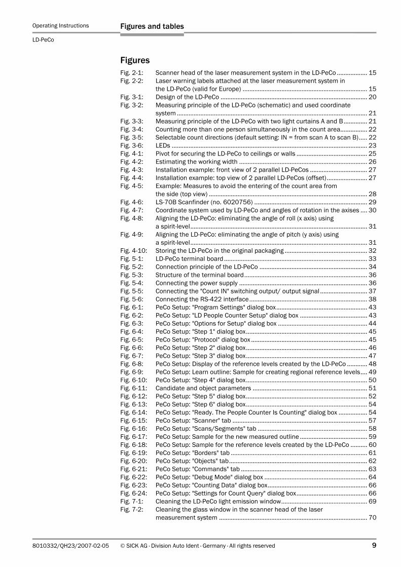
FiguresFig. 2-1: Scanner head of the laser measurement system in the LD-PeCo .................. 15Fig. 2-2: Laser warning labels attached at the laser measurement system in
the LD-PeCo (valid for Europe) .......................................................................... 15Fig. 3-1: Design of the LD-PeCo ....................................................................................... 20Fig. 3-2: Measuring principle of the LD-PeCo (schematic) and used coordinate
system ................................................................................................................. 21Fig. 3-3: Measuring principle of the LD-PeCo with two light curtains A and B.............. 21Fig. 3-4: Counting more than one person simultaneously in the count area................ 22Fig. 3-5: Selectable count directions (default setting: IN = from scan A to scan B)..... 22Fig. 3-6: LEDs .................................................................................................................... 23Fig. 4-1: Pivot for securing the LD-PeCo to ceilings or walls .......................................... 25Fig. 4-2: Estimating the working width ............................................................................ 26Fig. 4-3: Installation example: front view of 2 parallel LD-PeCos .................................. 27Fig. 4-4: Installation example: top view of 2 parallel LD-PeCos (offset)........................ 27Fig. 4-5: Example: Measures to avoid the entering of the count area from
the side (top view) .............................................................................................. 28Fig. 4-6: LS-70B Scanfinder (no. 6020756) ................................................................... 29Fig. 4-7: Coordinate system used by LD-PeCo and angles of rotation in the axises .... 30Fig. 4-8: Aligning the LD-PeCo: eliminating the angle of roll (x axis) using
a spirit-level......................................................................................................... 31Fig. 4-9: Aligning the LD-PeCo: eliminating the angle of pitch (y axis) using
a spirit-level......................................................................................................... 31Fig. 4-10: Storing the LD-PeCo in the original packaging ................................................. 32Fig. 5-1: LD-PeCo terminal board ..................................................................................... 33Fig. 5-2: Connection principle of the LD-PeCo ................................................................ 34Fig. 5-3: Structure of the terminal board......................................................................... 36Fig. 5-4: Connecting the power supply ............................................................................ 36Fig. 5-5: Connecting the "Count IN" switching output/ output signal ............................ 37Fig. 5-6: Connecting the RS-422 interface...................................................................... 38Fig. 6-1: PeCo Setup: "Program Settings" dialog box...................................................... 43Fig. 6-2: PeCo Setup: "LD People Counter Setup" dialog box ........................................ 43Fig. 6-3: PeCo Setup: "Options for Setup" dialog box ..................................................... 44Fig. 6-4: PeCo Setup: "Step 1" dialog box........................................................................ 45Fig. 6-5: PeCo Setup: "Protocol" dialog box ..................................................................... 45Fig. 6-6: PeCo Setup: "Step 2" dialog box........................................................................ 46Fig. 6-7: PeCo Setup: "Step 3" dialog box........................................................................ 47Fig. 6-8: PeCo Setup: Display of the reference levels created by the LD-PeCo ............ 48Fig. 6-9: PeCo Setup: Learn outline: Sample for creating regional reference levels.... 49Fig. 6-10: PeCo Setup: "Step 4" dialog box........................................................................ 50Fig. 6-11: Candidate and object parameters .................................................................... 51Fig. 6-12: PeCo Setup: "Step 5" dialog box........................................................................ 52Fig. 6-13: PeCo Setup: "Step 6" dialog box........................................................................ 54Fig. 6-14: PeCo Setup: "Ready. The People Counter Is Counting" dialog box ................. 54Fig. 6-15: PeCo Setup: "Scanner" tab ................................................................................ 57Fig. 6-16: PeCo Setup: "Scans/Segments" tab ................................................................. 58Fig. 6-17: PeCo Setup: Sample for the new measured outline ........................................ 59Fig. 6-18: PeCo Setup: Sample for the reference levels created by the LD-PeCo .......... 60Fig. 6-19: PeCo Setup: "Borders" tab ................................................................................. 61Fig. 6-20: PeCo Setup: "Objects" tab.................................................................................. 62Fig. 6-21: PeCo Setup: "Commands" tab ........................................................................... 63Fig. 6-22: PeCo Setup: "Debug Mode" dialog box ............................................................. 64Fig. 6-23: PeCo Setup: "Counting Data" dialog box........................................................... 66Fig. 6-24: PeCo Setup: "Settings for Count Query" dialog box.......................................... 66Fig. 7-1: Cleaning the LD-PeCo light emission window................................................... 69Fig. 7-2: Cleaning the glass window in the scanner head of the laser
measurement system ........................................................................................ 70
Operating Instructions
LD-PeCo People Counter
10 © SICK AG · Division Auto Ident · Germany · All rights reserved 8010332/QH23/2007-02-05
Figures and tables
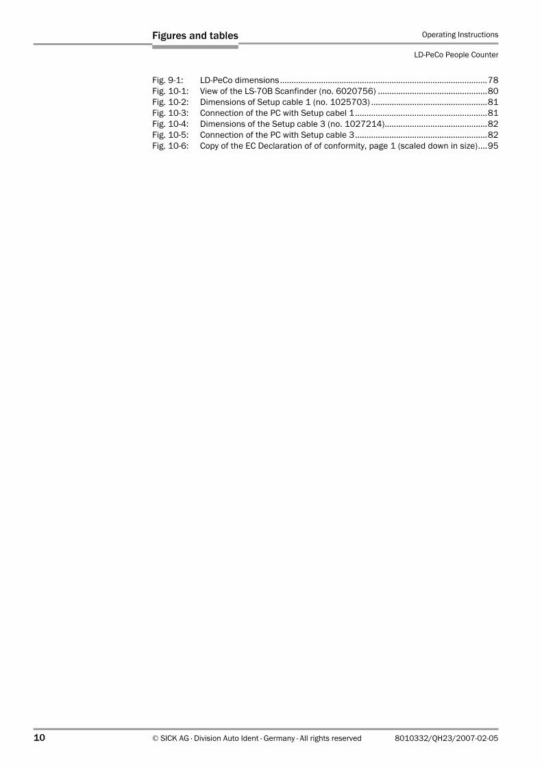
Fig. 9-1: LD-PeCo dimensions...........................................................................................78Fig. 10-1: View of the LS-70B Scanfinder (no. 6020756) ................................................80Fig. 10-2: Dimensions of Setup cable 1 (no. 1025703) ...................................................81Fig. 10-3: Connection of the PC with Setup cabel 1..........................................................81Fig. 10-4: Dimensions of the Setup cable 3 (no. 1027214).............................................82Fig. 10-5: Connection of the PC with Setup cable 3..........................................................82Fig. 10-6: Copy of the EC Declaration of of conformity, page 1 (scaled down in size)....95
Operating Instructions Chapter 1
LD-PeCo
Notes On This Document
8010332/QH23/2007-02-05 © SICK AG · Division Auto Ident · Germany · All rights reserved 11
1 Notes On This Document
1.1 Function
This document instructs you on using the LD-PeCo people counter in the following variants:
• LD-PeCo with RS-422 data interface (mounting height of between 2.5 m (8.2 ft) and 5.5 m (18 ft))
• LD-PeCo with RS-422 data interface (mounting height of between 5.5 m (18 ft) and 15 m (49.2 ft))
The LD-PeCo is based on the LD-OEM laser measurement system and is used with an internal application (program) for counting people.
The document contains information on:
• Assembly and electrical installation• Commissioning• Operation and configuration (parameterization)• Maintenance• Replacing devices and transferring parameter sets
Note From this point on, the people counter and all its variants will simply be referred to as "LD-PeCo" (unless a distinction is required).
1.2 Target audience
This document is aimed at those who carry out the following activities:
1.2.1 Assembly, Electrical Installation, Maintenance, and Replacement
Electricians and service technicians
1.2.2 Commissioning, Operation, and Configuration
Technicians and engineers
1.3 Information Content
This document contains all the information required for assembling, electrically installing, and commissioning the LD-PeCo with the factory default settings. Step-by-step instructions are provided for all the relevant activities.
The PeCo Setup configuration software is used to configure the LD-PeCo for application-specific situations and to request the measurement values for displaying the count results on a PC.
For further information on laser measuring technology, please contact the Auto Ident division at SICK AG or visit the SICK Web site at www.sick.com.
Chapter 1 Operating Instructions
LD-PeCo People Counter
12 © SICK AG · Division Auto Ident · Germany · All rights reserved 8010332/QH23/2007-02-05
Notes On This Document
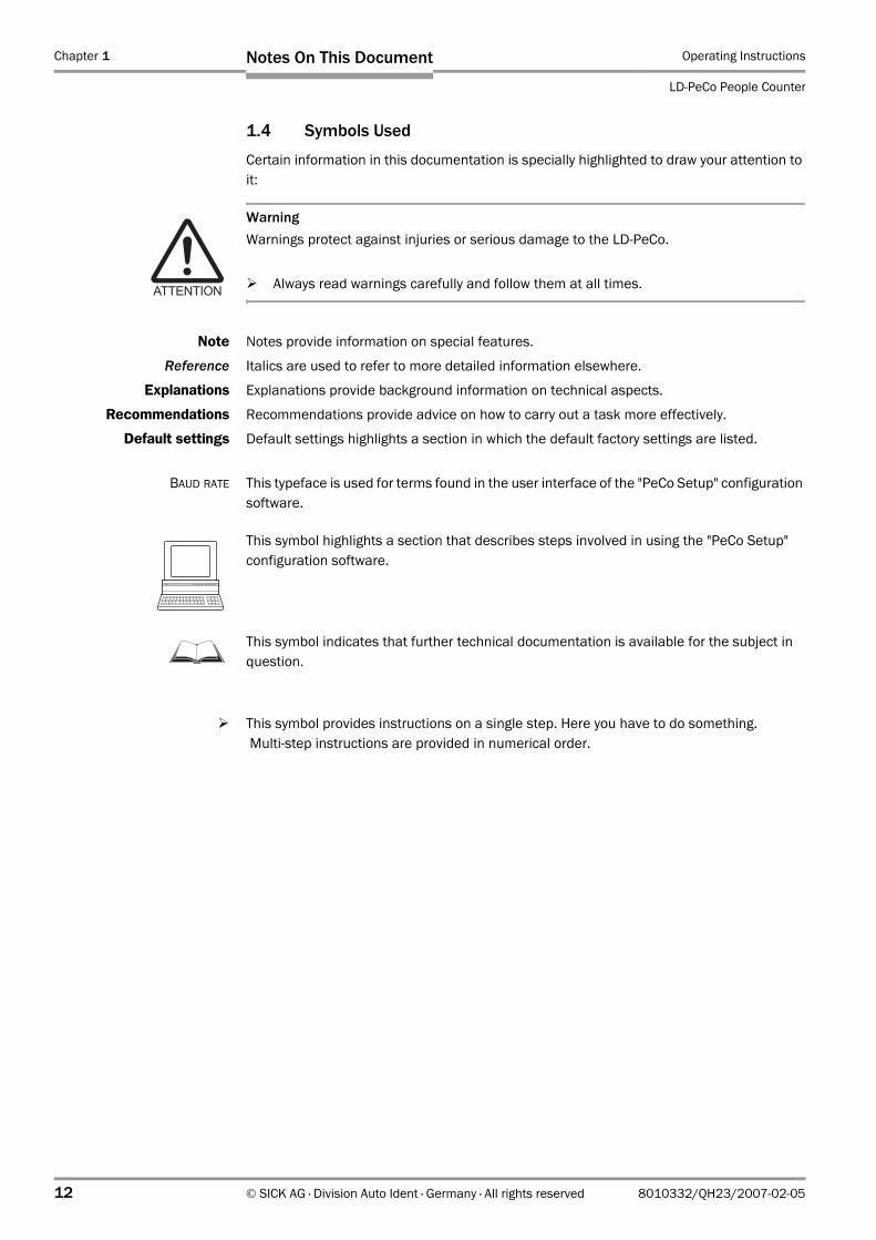
1.4 Symbols Used
Certain information in this documentation is specially highlighted to draw your attention to it:
WarningWarnings protect against injuries or serious damage to the LD-PeCo.
Always read warnings carefully and follow them at all times.
Note Notes provide information on special features.
Reference Italics are used to refer to more detailed information elsewhere.
Explanations Explanations provide background information on technical aspects.
Recommendations Recommendations provide advice on how to carry out a task more effectively.
Default settings Default settings highlights a section in which the default factory settings are listed.
BAUD RATE This typeface is used for terms found in the user interface of the "PeCo Setup" configuration software.
This symbol highlights a section that describes steps involved in using the "PeCo Setup" configuration software.
This symbol indicates that further technical documentation is available for the subject in question.
This symbol provides instructions on a single step. Here you have to do something. Multi-step instructions are provided in numerical order.
Operating Instructions Chapter 2
LD-PeCo
Safety Information
8010332/QH23/2007-02-05 © SICK AG · Division Auto Ident · Germany · All rights reserved 13
2 Safety Information
2.1 Safety Standards
The LD-PeCo was designed and manufactured taking into account a hazards analysis and in accordance with carefully selected, harmonized standards, as well as other technical specifications. As a result, the LD-PeCo meets the current technical requirements.
The recognized technical regulations were applied and observed during development and production. The standard of quality is ensured by a certified quality management system to DIN EN ISO 9001: 2000 during development and production at SICK AG.
Users who operate the device correctly will be sufficiently protected provided that they observe all the safety information supplied in these operating instructions.
2.2 Authorized users
To ensure that the LD-PeCo operates correctly and safely, it must be installed and operated by sufficiently qualified personnel.
The following qualifications are required for the various activities:
2.2.1 Assembly and Maintenance
• Practical training in electrical engineering• Knowledge of the current safety regulations at the workplace
2.2.2 Electrical Installation and Device Replacement
• Practical training in electrical engineering• Knowledge of the relevant safety guidelines
2.2.3 Commissioning, Operation, and Configuration
• PC skills (WindowsTM operating system)• Basic knowledge of data transfer processes
2.2.4 Processing Measured Values in IT Systems
• Knowledge of programming applications
2.3 Intended Use
The LD-PeCo is a non-contact person counter designed for stand-alone operation in commercial and light industrial environments as well as the residential environment.
It is ideal for determining and analyzing visitor flows in shopping centers, department stores, or event centers, and can also be used for building control purposes (e.g. controlling the air conditioning). The LD-PeCo outputs count data via the data interface as well as count pulses via its switching outputs. The count data for incoming and outgoing persons depend on moving direction.
Implementing the device in any other applications, modifying it in any way, whether during mounting or electrical installation, will result in an annulment of any warranty claims vis-à-vis SICK AG.
Chapter 2 Operating Instructions
LD-PeCo People Counter
14 © SICK AG · Division Auto Ident · Germany · All rights reserved 8010332/QH23/2007-02-05
Safety Information
The LD-PeCo operator must ensure that:
• The device is only implemented in accordance with the named specifications and environmental conditions (see Chapter 9.2 Data Sheet LD-PeCo People Counter, Page 77).
• The country-specific operating standards and guidelines are taken into account for application.
• The device is fully operational when in use.• Safety and warning labels attached to the device must not be removed or covered.
These must also be legible at all times.• The operating instructions are kept on site in good condition and authorized personnel
are proven to be sufficiently qualified.• Repairs are only carried out by trained and authorized service personnel employed by
SICK AG.
Annulment of the manufacturer warranty
The housing screws of the laser measurement system in the LD-PeCo are sealed. Damaging the seals and opening the device will result in an annulment of the manufacturer warranty. The housing must only be opened by authorized service personnel.Handling the device incorrectly may result in electric shocks or increased laser radiation.
2.4 Operating Reliability
The LD-PeCo carries out continuous self-tests to ensure a high degree of operational reliability. Independent test routines monitor all the main components.
2.5 General Safety Information and Protection Measures
Read the general safety information thoroughly and observe it at all times when using the LD-PeCo. In addition, observe the warnings provided in these operating instructions.
2.5.1 Correct Use
The LD-PeCo is not a deivce for protecting persons as defined by current machine safety standards.
2.5.2 Electrical Installation
Danger of injury through electrical current
The LD-PeCo requires a 24 V DC power supply.A maximum of 270 V is generated in the LD-PeCo scanner during operation!
To connect the device, only open the cover of the LD-PeCo housing.
Do not under any circumstances open the laser measurement system housing (sealed) in the LD-PeCo.
When using electrical systems, observe the standard safety precautions.
Operating Instructions Chapter 2
LD-PeCo
Safety Information
8010332/QH23/2007-02-05 © SICK AG · Division Auto Ident · Germany · All rights reserved 15
2.5.3 Laser Safety
Laser RadiationThe LD-PeCo uses a class 1 (eye safe) infrared laser beam. The laser beam is invisible to the human eye.
Caution — use of controls or adjustments or performance of procedures other than those specified herein may result in hazardous radiation exposure.
Do not open the housing of the laser measurement system in the LD-PeCo (opening the housing does not interrupt the laser beam).
Observe the laser safety standards (latest version).
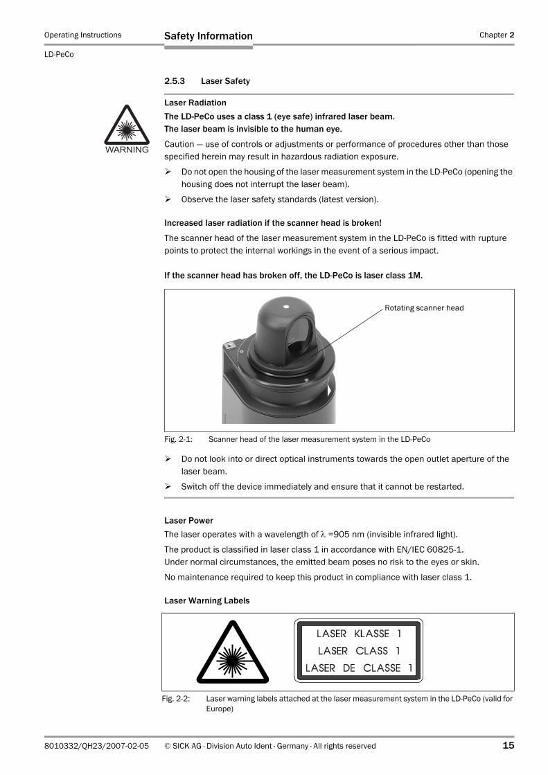
Increased laser radiation if the scanner head is broken!
The scanner head of the laser measurement system in the LD-PeCo is fitted with rupture points to protect the internal workings in the event of a serious impact.
If the scanner head has broken off, the LD-PeCo is laser class 1M.
Do not look into or direct optical instruments towards the open outlet aperture of the laser beam.
Switch off the device immediately and ensure that it cannot be restarted.
Laser PowerThe laser operates with a wavelength of λ =905 nm (invisible infrared light).
The product is classified in laser class 1 in accordance with EN/IEC 60825-1.Under normal circumstances, the emitted beam poses no risk to the eyes or skin.
No maintenance required to keep this product in compliance with laser class 1.
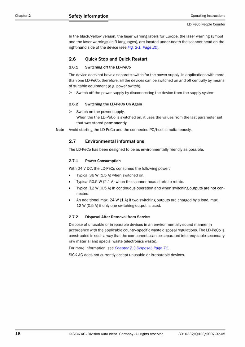
Laser Warning Labels
Fig. 2-1: Scanner head of the laser measurement system in the LD-PeCo
Rotating scanner head
Fig. 2-2: Laser warning labels attached at the laser measurement system in the LD-PeCo (valid for Europe)
Chapter 2 Operating Instructions
LD-PeCo People Counter
16 © SICK AG · Division Auto Ident · Germany · All rights reserved 8010332/QH23/2007-02-05
Safety Information
In the black/yellow version, the laser warning labels for Europe, the laser warning symbol and the laser warnings (in 3 languages), are located under-neath the scanner head on the right-hand side of the device (see Fig. 3-1, Page 20).
2.6 Quick Stop and Quick Restart
2.6.1 Switching off the LD-PeCo
The device does not have a separate switch for the power supply. In applications with more than one LD-PeCo, therefore, all the devices can be switched on and off centrally by means of suitable equipment (e.g. power switch).
Switch off the power supply by disconnecting the device from the supply system.
2.6.2 Switching the LD-PeCo On Again
Switch on the power supply.When the the LD-PeCo is switched on, it uses the values from the last parameter set that was stored permanently.
Note Avoid starting the LD-PeCo and the connected PC/host simultaneously.
2.7 Environmental informations
The LD-PeCo has been designed to be as environmentally friendly as possible.
2.7.1 Power Consumption
With 24 V DC, the LD-PeCo consumes the following power:
• Typical 36 W (1.5 A) when switched on.• Typical 50.5 W (2.1 A) when the scanner head starts to rotate.• Typical 12 W (0.5 A) in continuous operation and when switching outputs are not con-
nected.• An additional max. 24 W (1 A) if two switching outputs are charged by a load, max.
12 W (0.5 A) if only one switching output is used.
2.7.2 Disposal After Removal from Service
Dispose of unusable or irreparable devices in an environmentally-sound manner in accordance with the applicable country-specific waste disposal regulations. The LD-PeCo is constructed in such a way that the components can be separated into recyclable secondary raw material and special waste (electronics waste).
For more information, see Chapter 7.3 Disposal, Page 71.
SICK AG does not currently accept unusable or irreparable devices.

Operating Instructions Chapter 3
LD-PeCo
Product Description
8010332/QH23/2007-02-05 © SICK AG · Division Auto Ident · Germany · All rights reserved 17
3 Product Description
3.1 Device Structure
3.1.1 Delivered Components
The LD-PeCo is supplied with the following:
• An information sheet (notes on device) with a terminal diagram and Quick Start instructions.
• A pipe clamping system with pivot, pipe and safety cord.
Depending on the number of devices ordered, one or more copies of the following are supplied:
• CD ROM (no. 2027077) with– The PC software "PeCo Setup" for WindowsTM
– Operating instructions LD-PeCo in English and German (PDF files)– The freely-available PC software "Acrobat Reader" for displaying PDF files
Note The latest versions of all the current publications/programs on the CD ROM can also be downloaded from www.sick.com.
Depending on the number of copies ordered at the time of purchasing, the following are supplied (optional):
• Printed copy of the operating instructions LD-PeCo in German and/or English
Chapter 10.2 Available Accessories, Page 2 provides an overview of the mounting accessories, cables and laser detectors that are available.
3.1.2 Device Variants
The LD-PeCo is available in the following variants:
3.1.3 System Requirements
The following are required for commissioning and operating the LD-PeCo by the user:
1. A 24 V DC ± 15 % power supply generated in accordance with IEC 364-4-41. (VDE 0100, Part 410). Minimum power output: 55 W.
2. To connect the power supply, you need a 2-core cable with a core diameter of at least 1 mm2 (18 AWG) and a maximum length of 20 m (65.6 ft), as well as an open cable end.
3. To connect the two switching outputs, you need a 4-core cable with a core diameter of at least 0.25 mm2 (24 AWG), at a maximum length of 50 m (164 ft) at least 0.5 mm2 (20 AWG), as well as an open cable end.
4. To connect the LD-PeCo to an IT system for processing the data (application dependent), you need a shielded RS 422 data cable with open cable end.
5. To configure the LD-PeCo, you need a suitable data cable with 9-pin D Sub sockets to connect the PC temporarily to the RS 422 interface. The prefabricated setup cable 1 (no. 1025703) with integrated power supply lines is available (see Chapter 10.2 Available Accessories, Page 80).
Type Order No. Data Interfaces
LD-PeCo 5.5 m (18 ft) 1023382 RS 422
LD-PeCo 15 m (49.2 ft) 1023383 RS 422
Table 3-1: LD-PeCo variants
Chapter 3 Operating Instructions
LD-PeCo People Counter
18 © SICK AG · Division Auto Ident · Germany · All rights reserved 8010332/QH23/2007-02-05
Product Description
6. An RS 422/RS 232 interface converter for the RS 232 interface of the PC,e.g. B&B Model 4WSDR9 (information in the internet at www.bb-elec.com).The pin assignment of setup cable 1 is defined for the RS 422/RS 232 interface converter B&B Model 4WSDR9. The RS 232 interface of the PC provides the power supply for this converter.
7. To connect the RS 422/RS 232 interface converter to the PC, you need an RS 232 data cable with 1:1 pin assignment (extension cable).
8. A PC (min. 80486, 66 MHz, 16 MB RAM, CD drive, serial interface, mouse (recommended)) with the following operating systems: Windows 95TM/98TM, Windows NT4.0TM, Windows 2000TM, or Windows XPTM.
3.1.4 Product Features and Functions (Overview)
General benefits of the system• It reliably counts several persons moving side by side and one after the other.• It determines the direction in which the persons are moving.• It is vandal proof because it is located beyond reach.
Safety and user-friendliness:• Laser class 1 (the laser diode is switched off if problems arise with the laser beam).• Future compatible with firmware update via the serial data interface (Flash PROM).• Low power consumption.
Simple operation/parameterization:• Configuration with the "PeCo Setup" PC-software for Windows.
Operating modes:• Setup: step-by-step configuration of the LD-PeCo.• Maintenance: control and optimization of a working LD-PeCo.• Counter Reading: count data display, reset and logging.
Result output:• Via data interface• Via switching outputs/LEDs
Electrical interfaces:• Power supply (24 V DC).• 2 switching outputs (Count IN, Count OUT).• RS 422 data interface, fixed to: 19,200 Bd, 8 data bits, 1 stop bit, no parity.
Connection method:• All the connections are made via a terminal board (10-core terminal strip).• Special setup cables (data/power supply) to configure the system.
Operating Instructions Chapter 3
LD-PeCo
Product Description
8010332/QH23/2007-02-05 © SICK AG · Division Auto Ident · Germany · All rights reserved 19
3.1.5 Applications
The LD-PeCo is used for counting people.
The data collected can be processed externally to determine and analyze visitor flows in shopping centers, department stores, or event centers, and can also be used for building control purposes (e.g. controlling the air conditioning).
General• Recording visitor numbers.
Building management • Controlling air-conditioning systems• Signals for alarm systems• Access control
Department stores / shopping centers• Person flows within a building (number of visitors to different departments)• Scheduling sales staff according to requirements• Conversion rates (performance of sales staff) • Measuring the effectiveness of promotions• Visitor behavior (from browser to buyer)• Increasing the value of an establishment in relation to the number of visitors• Comparing different shopping centers (expenditure/number of visitors)
Airports• Counting people in public areas• Counting people in sanitation facilities (cleaning)• Counting people in baggage collection/immigration area• Counting people in inspection and control zones• Counting authorized personnel in restricted areas• Counting people in the passenger bridges• Distribution of people in large-capacity aircraft• Managing parking areas
Stations• Overall determination of daily, monthly, and yearly passenger flows• Determining zones with low and high frequency of visitors• Determining the influence of internal and external events• Ratio of travellers/accompanying persons/visitors• Managing parking areas• Improving punctuality by eliminating bottlenecks
Chapter 3 Operating Instructions
LD-PeCo People Counter
20 © SICK AG · Division Auto Ident · Germany · All rights reserved 8010332/QH23/2007-02-05
Product Description
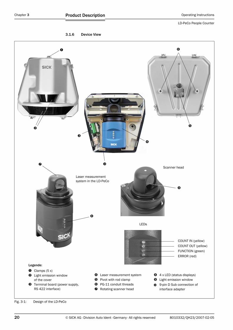
3.1.6 Device View
Fig. 3-1: Design of the LD-PeCo
➐
➑
➒
COUNT IN (yellow)COUNT OUT (yellow)FUNCTION (green)ERROR (red)
LEDs
➊
Scanner head
➋
Laser measurement system in the LD-PeCo
➏
➌
➎
➍
BL
➑ 4 x LED (status displays)➒ Light emission windowBL 9-pin D Sub connection of
interface adapter
Legende:➊ Clamps (5 x)➋ Light emission window
of the cover➌ Terminal board (power supply,
RS 422 interface)
➍ Laser measurement system➎ Pivot with rod clamp➏ PG-11 conduit threads➐ Rotating scanner head
Operating Instructions Chapter 3
LD-PeCo
Product Description
8010332/QH23/2007-02-05 © SICK AG · Division Auto Ident · Germany · All rights reserved 21
3.2 Operating Principle
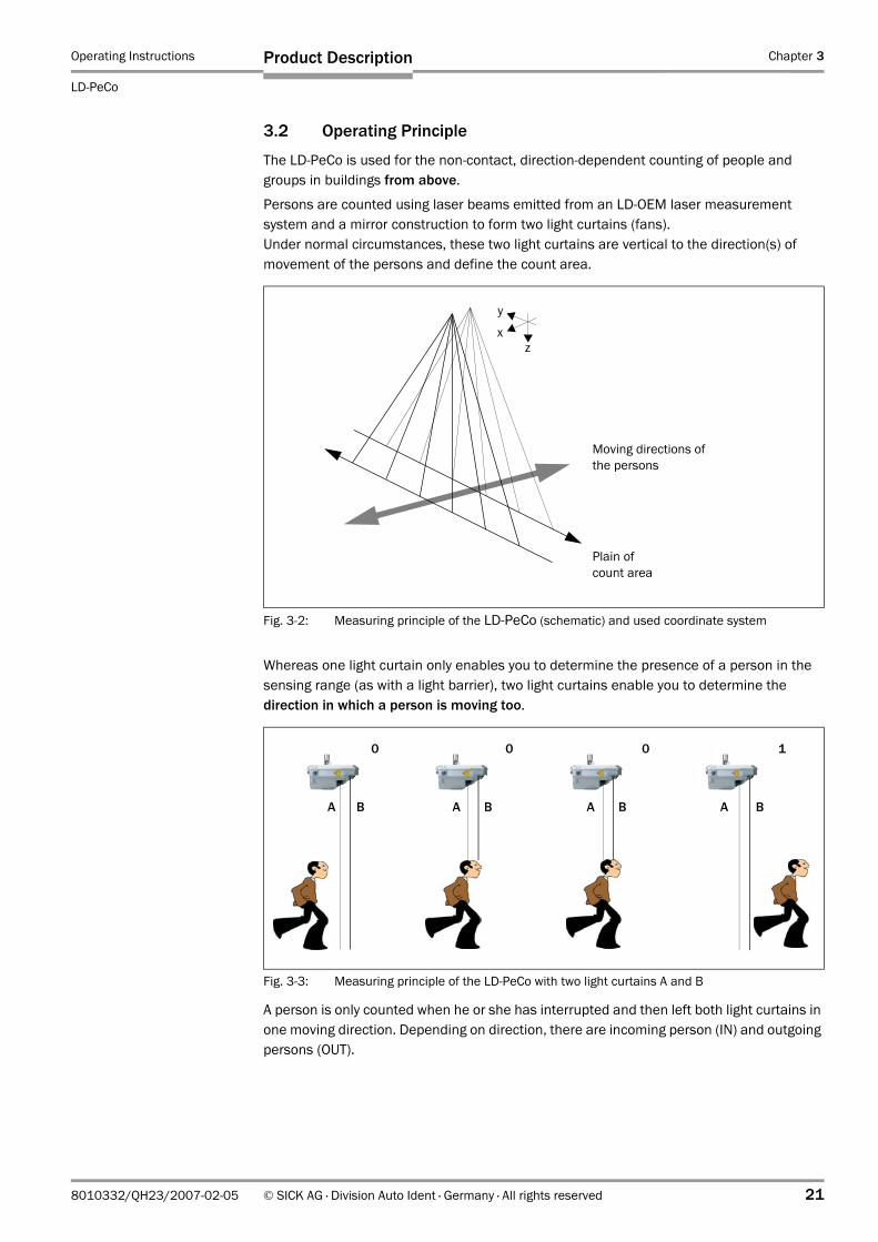
The LD-PeCo is used for the non-contact, direction-dependent counting of people and groups in buildings from above.
Persons are counted using laser beams emitted from an LD-OEM laser measurement system and a mirror construction to form two light curtains (fans). Under normal circumstances, these two light curtains are vertical to the direction(s) of movement of the persons and define the count area.
Whereas one light curtain only enables you to determine the presence of a person in the sensing range (as with a light barrier), two light curtains enable you to determine the direction in which a person is moving too.
A person is only counted when he or she has interrupted and then left both light curtains in one moving direction. Depending on direction, there are incoming person (IN) and outgoing persons (OUT).
Fig. 3-2: Measuring principle of the LD-PeCo (schematic) and used coordinate system
Moving directions of the persons
Plain of count area
y
xz
Fig. 3-3: Measuring principle of the LD-PeCo with two light curtains A and B
0 0 0 1
A B A B A B A B
Chapter 3 Operating Instructions
LD-PeCo People Counter
22 © SICK AG · Division Auto Ident · Germany · All rights reserved 8010332/QH23/2007-02-05
Product Description
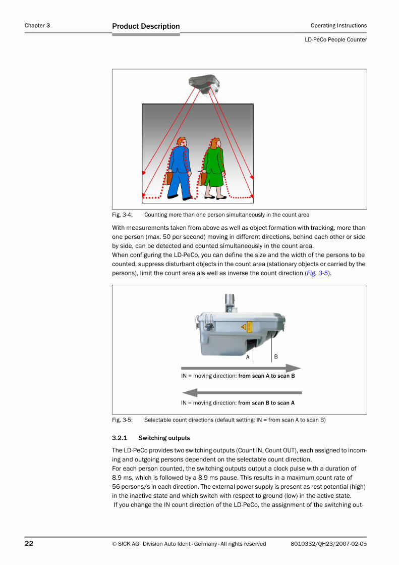
With measurements taken from above as well as object formation with tracking, more than one person (max. 50 per second) moving in different directions, behind each other or side by side, can be detected and counted simultaneously in the count area. When configuring the LD-PeCo, you can define the size and the width of the persons to be counted, suppress disturbant objects in the count area (stationary objects or carried by the persons), limit the count area als well as inverse the count direction (Fig. 3-5).
3.2.1 Switching outputs
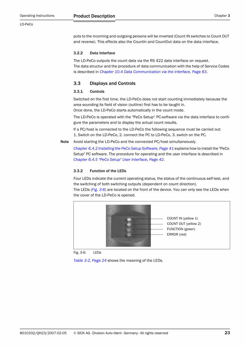
The LD-PeCo provides two switching outputs (Count IN, Count OUT), each assigned to incom-ing and outgoing persons dependent on the selectable count direction.For each person counted, the switching outputs output a clock pulse with a duration of 8.9 ms, which is followed by a 8.9 ms pause. This results in a maximum count rate of 56 persons/s in each direction. The external power supply is present as rest potential (high) in the inactive state and which switch with respect to ground (low) in the active state. If you change the IN count direction of the LD-PeCo, the assignment of the switching out-
Fig. 3-4: Counting more than one person simultaneously in the count area
Fig. 3-5: Selectable count directions (default setting: IN = from scan A to scan B)
IN = moving direction: from scan A to scan B
IN = moving direction: from scan B to scan A
A B
Operating Instructions Chapter 3
LD-PeCo
Product Description
8010332/QH23/2007-02-05 © SICK AG · Division Auto Ident · Germany · All rights reserved 23
puts to the incoming and outgoing persons will be inverted (Count IN switches to Count OUT and reverse). This effects also the CountIn and CountOut data on the data interface.
3.2.2 Data Interface
The LD-PeCo outputs the count data via the RS 422 data interface on request.The data structur and the procedure of data communication with the help of Service Codes is described in Chapter 10.4 Data Communication via the Interface, Page 83.
3.3 Displays and Controls
3.3.1 Controls
Switched on the first time, the LD-PeCo does not start counting immediately because the area sounding its field of vision (outline) first has to be taught in.Once done, the LD-PeCo starts automatically in the count mode.
The LD-PeCo is operated with the "PeCo Setup“ PC-software via the data interface to confi-gure the parameters and to display the actual count results.
If a PC/host is connected to the LD-PeCo the following sequence must be carried out:1. Switch on the LD-PeCo, 2. connect the PC to LD-PeCo, 3. switch on the PC.
Note Avoid starting the LD-PeCo and the connected PC/host simultaneously.
Chapter 6.4.2 Installing the PeCo Setup Software, Page 41 explains how to install the "PeCo Setup" PC software. The procedure for operating and the user interface is described in Chapter 6.4.5 "PeCo Setup" User Interface, Page 42.
3.3.2 Function of the LEDs
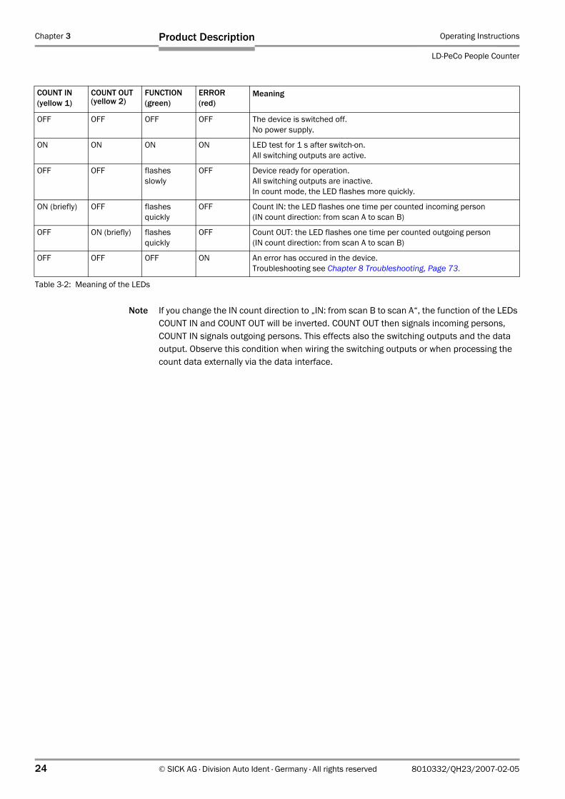
Four LEDs indicate the current operating status, the status of the continuous self-test, and the switching of both switching outputs (dependent on count direction). The LEDs (Fig. 3-6) are located on the front of the device. You can only see the LEDs when the cover of the LD-PeCo is opened.
Table 3-2, Page 24 shows the meaning of the LEDs.
Fig. 3-6: LEDs
COUNT IN (yellow 1)COUNT OUT (yellow 2)FUNCTION (green) ERROR (red)
Chapter 3 Operating Instructions
LD-PeCo People Counter
24 © SICK AG · Division Auto Ident · Germany · All rights reserved 8010332/QH23/2007-02-05
Product Description
Note If you change the IN count direction to „IN: from scan B to scan A“, the function of the LEDs COUNT IN and COUNT OUT will be inverted. COUNT OUT then signals incoming persons, COUNT IN signals outgoing persons. This effects also the switching outputs and the data output. Observe this condition when wiring the switching outputs or when processing the count data externally via the data interface.
COUNT IN(yellow 1)
COUNT OUT(yellow 2)
FUNCTION(green)
ERROR(red)
Meaning
OFF OFF OFF OFF The device is switched off.No power supply.
ON ON ON ON LED test for 1 s after switch-on.All switching outputs are active.
OFF OFF flashesslowly
OFF Device ready for operation.All switching outputs are inactive.In count mode, the LED flashes more quickly.
ON (briefly) OFF flashesquickly
OFF Count IN: the LED flashes one time per counted incoming person (IN count direction: from scan A to scan B)
OFF ON (briefly) flashesquickly
OFF Count OUT: the LED flashes one time per counted outgoing person(IN count direction: from scan A to scan B)
OFF OFF OFF ON An error has occured in the device.Troubleshooting see Chapter 8 Troubleshooting, Page 73.
Table 3-2: Meaning of the LEDs
Operating Instructions Chapter 4
LD-PeCo
Assembly
8010332/QH23/2007-02-05 © SICK AG · Division Auto Ident · Germany · All rights reserved 25
4 Assembly
4.1 Overview of the Assembly Steps
• Select the mounting location for the LD-PeCo.• Mount and adjust the LD-PeCo.
4.2 Preparations for Installation
4.2.1 Ensure that you have all the required components.
• LD-PeCo people counter
4.2.2 Preparing the Accessories
• SICK pipe clamping system for the LD-PeCo, included in the LD-PeCo scope of delivery:– Pivot no. 4039006 for mounting on ceilings or on walls.– Assembly pipe no. 5311055 (length = 130 mm (4.26 in),
diameter = 30 mm (1.2 in)).– Safety cord no. 1025633 with thimbles and carabiners.
4.2.3 Auxiliary Parts
• 4 M 6 screws for securing the LD-PeCo to ceilings or walls.The length of the screws depends on the wall thickness of the base.
• Tool• LS-70B Scanfinder no. 6020756, not included in the LD-PeCo scope of delivery.
4.2.4 Selecting the Mounting Location
Mount the LD-PeCo in such a way that it is protected from direct sunlight.Avoid mounting the LD-PeCo above grounds made by glass or stainless steel.
Note To prevent condensation in the LD-PeCo, make sure that the device is not subject to rapid changes in temperature.
4.2.5 Mounting Accessories
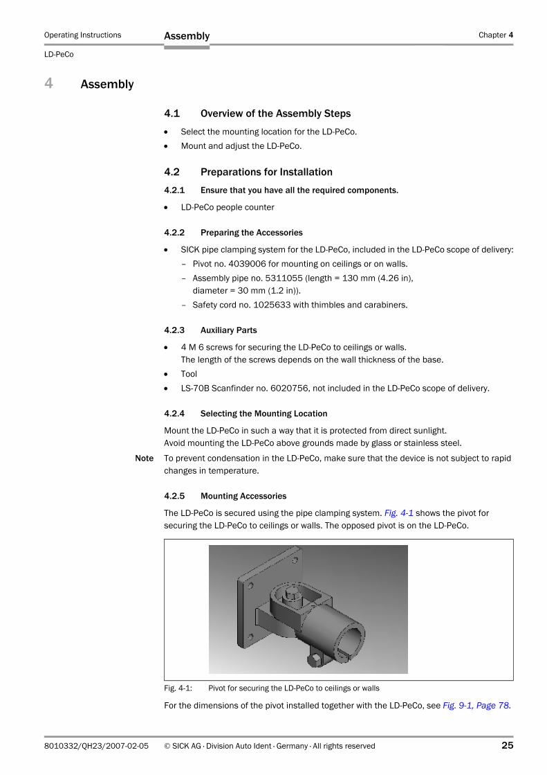
The LD-PeCo is secured using the pipe clamping system. Fig. 4-1 shows the pivot for securing the LD-PeCo to ceilings or walls. The opposed pivot is on the LD-PeCo.
For the dimensions of the pivot installed together with the LD-PeCo, see Fig. 9-1, Page 78.
Fig. 4-1: Pivot for securing the LD-PeCo to ceilings or walls
Chapter 4 Operating Instructions
LD-PeCo People Counter
26 © SICK AG · Division Auto Ident · Germany · All rights reserved 8010332/QH23/2007-02-05
Assembly
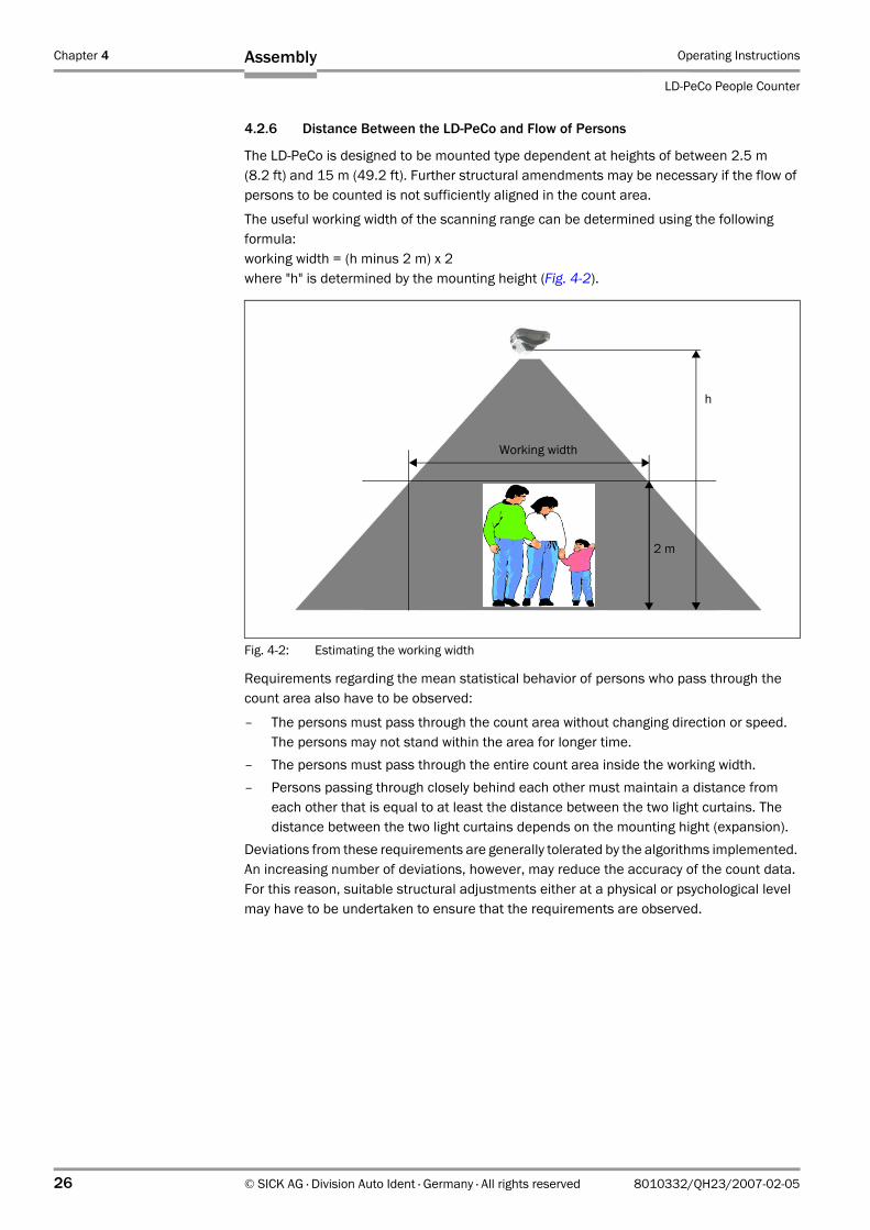
4.2.6 Distance Between the LD-PeCo and Flow of Persons
The LD-PeCo is designed to be mounted type dependent at heights of between 2.5 m (8.2 ft) and 15 m (49.2 ft). Further structural amendments may be necessary if the flow of persons to be counted is not sufficiently aligned in the count area.
The useful working width of the scanning range can be determined using the following formula: working width = (h minus 2 m) x 2 where "h" is determined by the mounting height (Fig. 4-2).
Requirements regarding the mean statistical behavior of persons who pass through the count area also have to be observed:
– The persons must pass through the count area without changing direction or speed.The persons may not stand within the area for longer time.
– The persons must pass through the entire count area inside the working width.– Persons passing through closely behind each other must maintain a distance from
each other that is equal to at least the distance between the two light curtains. The distance between the two light curtains depends on the mounting hight (expansion).
Deviations from these requirements are generally tolerated by the algorithms implemented. An increasing number of deviations, however, may reduce the accuracy of the count data. For this reason, suitable structural adjustments either at a physical or psychological level may have to be undertaken to ensure that the requirements are observed.
Fig. 4-2: Estimating the working width
h
Working width
2 m
Operating Instructions Chapter 4
LD-PeCo
Assembly
8010332/QH23/2007-02-05 © SICK AG · Division Auto Ident · Germany · All rights reserved 27
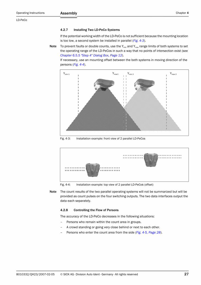
4.2.7 Installing Two LD-PeCo Systems
If the potential working width of the LD-PeCo is not sufficient because the mounting location is too low, a second system be installed in parallel (Fig. 4-3).
Note To prevent faults or double counts, use the Ymin and Ymax range limits of both systems to set the operating range of the LD-PeCos in such a way that no points of intersection exist (see Chapter 6.5.5 "Step 4" Dialog Box, Page 12).If necessary, use an mounting offset between the both systems in moving direction of the persons (Fig. 4-4).
Note The count results of the two parallel operating systems will not be summarized but will be provided as count pulses on the four switching outputs. The two data interfaces output the data each separately.
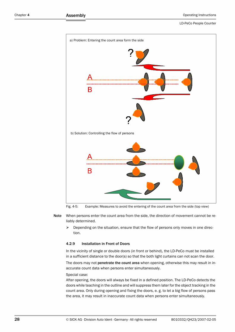
4.2.8 Controlling the Flow of Persons
The accuracy of the LD-PeCo decreases in the following situations:
– Persons who remain within the count area in groups.– A crowd standing or going very close behind or next to each other.– Persons who enter the count area from the side (Fig. 4-5, Page 28).
Fig. 4-3: Installation example: front view of 2 parallel LD-PeCos
Ymin 1 Ymax1 Ymin 2 Ymax 2
Fig. 4-4: Installation example: top view of 2 parallel LD-PeCos (offset)
Chapter 4 Operating Instructions
LD-PeCo People Counter
28 © SICK AG · Division Auto Ident · Germany · All rights reserved 8010332/QH23/2007-02-05
Assembly
Note When persons enter the count area from the side, the direction of movement cannot be re-liably determined.
Depending on the situation, ensure that the flow of persons only moves in one direc-tion.
4.2.9 Installation in Front of Doors
In the vicinity of single or double doors (in front or behind), the LD-PeCo must be installed in a sufficient distance to the door(s) so that the both light curtains can not scan the door.
The doors may not penetrate the count area when opening, otherwise this may result in in-accurate count data when persons enter simultaneously.
Special case:After opening, the doors will always be fixed in a defined position. The LD-PeCo detects the doors while teaching in the outline and will suppress them later for the object tracking in the count area. Only during opening and fixing the doors, e. g. to let a big flow of persons pass the area, it may result in inaccurate count data when persons enter simultaneously.
Fig. 4-5: Example: Measures to avoid the entering of the count area from the side (top view)
a) Problem: Entering the count area form the side
b) Solution: Controlling the flow of persons
Operating Instructions Chapter 4
LD-PeCo
Assembly
8010332/QH23/2007-02-05 © SICK AG · Division Auto Ident · Germany · All rights reserved 29
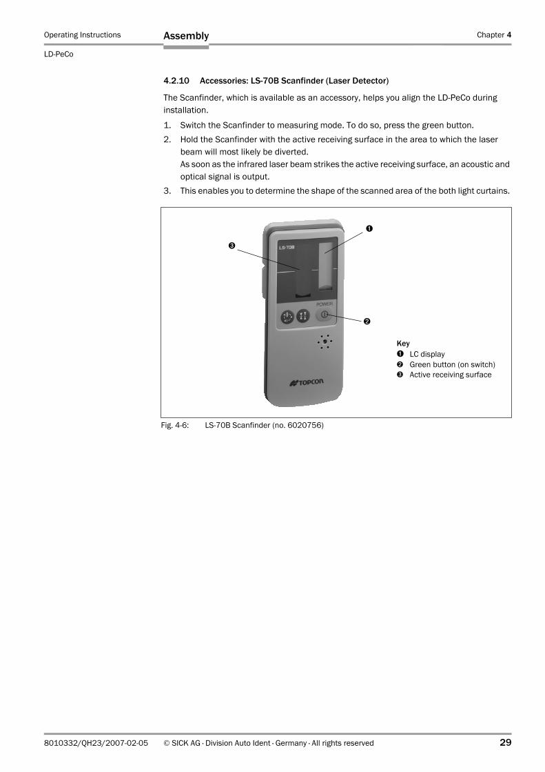
4.2.10 Accessories: LS-70B Scanfinder (Laser Detector)
The Scanfinder, which is available as an accessory, helps you align the LD-PeCo during installation.
1. Switch the Scanfinder to measuring mode. To do so, press the green button. 2. Hold the Scanfinder with the active receiving surface in the area to which the laser
beam will most likely be diverted. As soon as the infrared laser beam strikes the active receiving surface, an acoustic and optical signal is output.
3. This enables you to determine the shape of the scanned area of the both light curtains.
Fig. 4-6: LS-70B Scanfinder (no. 6020756)
Key➊ LC display➋ Green button (on switch)➌ Active receiving surface
➌
➊
➋
Chapter 4 Operating Instructions
LD-PeCo People Counter
30 © SICK AG · Division Auto Ident · Germany · All rights reserved 8010332/QH23/2007-02-05
Assembly
4.3 Mounting and Adjusting the Device
4.3.1 Mounting the LD-PeCo
To ensure that the device is installed securely to ceilings or walls, 4 M 6 screws with washers and retaining washers are required. The pipe fixing system uses pipes with a diameter of 30 mm (1.2 in). The power supply must be switched off.
The LD-PeCo can only be installed vertically.
Note Install the safety cord after mounting the LD-PeCo.
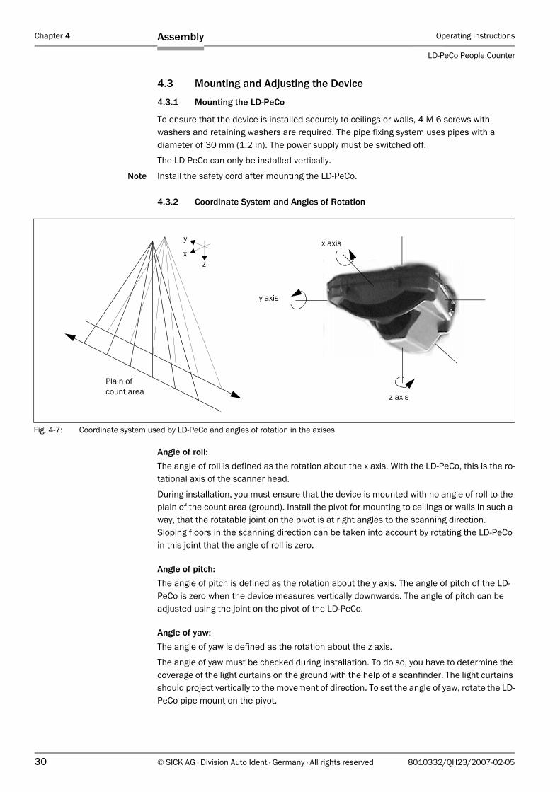
4.3.2 Coordinate System and Angles of Rotation
Angle of roll:The angle of roll is defined as the rotation about the x axis. With the LD-PeCo, this is the ro-tational axis of the scanner head.
During installation, you must ensure that the device is mounted with no angle of roll to the plain of the count area (ground). Install the pivot for mounting to ceilings or walls in such a way, that the rotatable joint on the pivot is at right angles to the scanning direction. Sloping floors in the scanning direction can be taken into account by rotating the LD-PeCo in this joint that the angle of roll is zero.
Angle of pitch:The angle of pitch is defined as the rotation about the y axis. The angle of pitch of the LD-PeCo is zero when the device measures vertically downwards. The angle of pitch can be adjusted using the joint on the pivot of the LD-PeCo.
Angle of yaw:The angle of yaw is defined as the rotation about the z axis.
The angle of yaw must be checked during installation. To do so, you have to determine the coverage of the light curtains on the ground with the help of a scanfinder. The light curtains should project vertically to the movement of direction. To set the angle of yaw, rotate the LD-PeCo pipe mount on the pivot.
Fig. 4-7: Coordinate system used by LD-PeCo and angles of rotation in the axises
y
xz
y axis
x axis
z axis
Plain of count area
Operating Instructions Chapter 4
LD-PeCo
Assembly
8010332/QH23/2007-02-05 © SICK AG · Division Auto Ident · Germany · All rights reserved 31
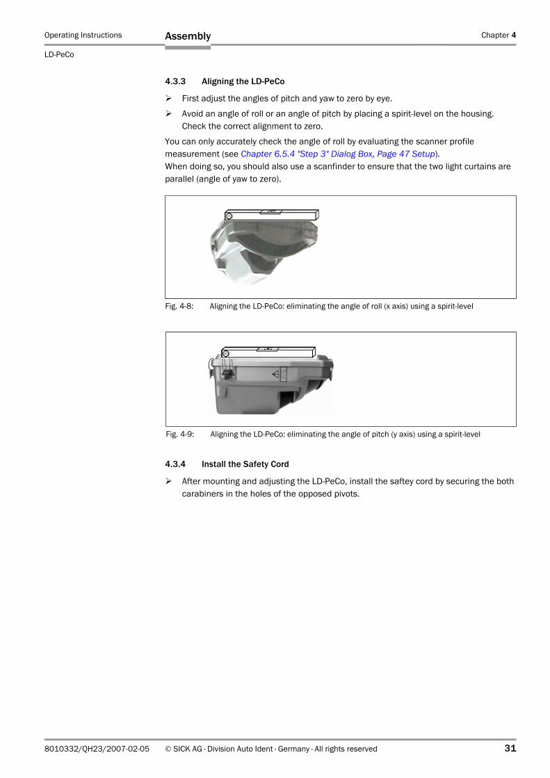
4.3.3 Aligning the LD-PeCo
First adjust the angles of pitch and yaw to zero by eye.
Avoid an angle of roll or an angle of pitch by placing a spirit-level on the housing. Check the correct alignment to zero.
You can only accurately check the angle of roll by evaluating the scanner profile measurement (see Chapter 6.5.4 "Step 3" Dialog Box, Page 47 Setup). When doing so, you should also use a scanfinder to ensure that the two light curtains are parallel (angle of yaw to zero).
4.3.4 Install the Safety Cord
After mounting and adjusting the LD-PeCo, install the saftey cord by securing the both carabiners in the holes of the opposed pivots.
Fig. 4-8: Aligning the LD-PeCo: eliminating the angle of roll (x axis) using a spirit-level
Fig. 4-9: Aligning the LD-PeCo: eliminating the angle of pitch (y axis) using a spirit-level
Chapter 4 Operating Instructions
LD-PeCo People Counter
32 © SICK AG · Division Auto Ident · Germany · All rights reserved 8010332/QH23/2007-02-05
Assembly
4.4 Disassembling the Device
1. Switch off the power supply to the LD-PeCo.2. Open the 5 clamps of the cover and remove the top cover.3. Remove the cables and pull them out through the conduit thread 11 connections.4. Loose the safety cord on the pivot of the LD-PeCo.5. Loose the rod clamp und remove the device from the pipe clamping system.
4.4.1 Storage
Material damageIncorrect storage can cause material damage to the LD-PeCo.Condensation can damage the optical components.
Prepare the device for storage.
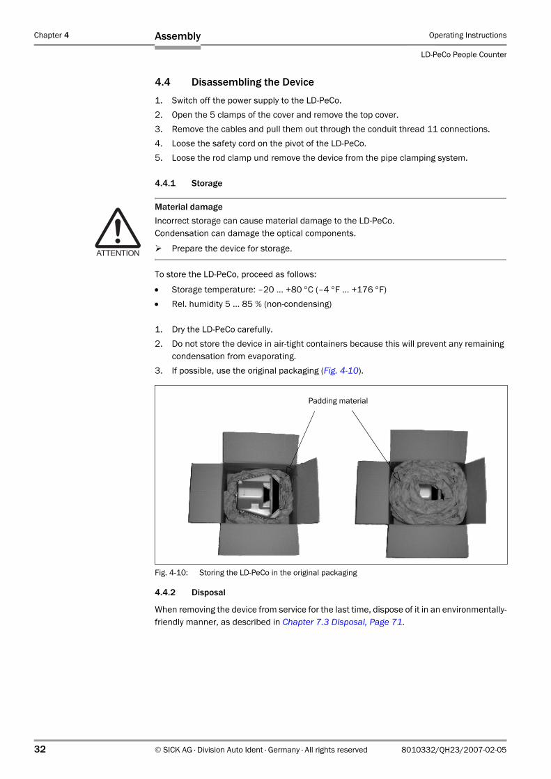
To store the LD-PeCo, proceed as follows:
• Storage temperature: –20 ... +80 °C (–4 °F ... +176 °F)• Rel. humidity 5 ... 85 % (non-condensing)
1. Dry the LD-PeCo carefully. 2. Do not store the device in air-tight containers because this will prevent any remaining
condensation from evaporating.3. If possible, use the original packaging (Fig. 4-10).
4.4.2 Disposal
When removing the device from service for the last time, dispose of it in an environmentally-friendly manner, as described in Chapter 7.3 Disposal, Page 71.
Fig. 4-10: Storing the LD-PeCo in the original packaging
Padding material
Operating Instructions Chapter 5
LD-PeCo
Electrical installation
8010332/QH23/2007-02-05 © SICK AG · Division Auto Ident · Germany · All rights reserved 33
5 Electrical installation
5.1 Installation Steps
• Connect the LD-PeCo to a 24 V DC power supply.• Connect the switching outputs (application dependent).• Connect the PC temporarily.• Connect the data interface for operation (application dependent).
5.2 Electrical Connections and Cables
To attach the cable connection, you have to open the LD-PeCo housing.
Open the 5 clamps and remove the top cover.
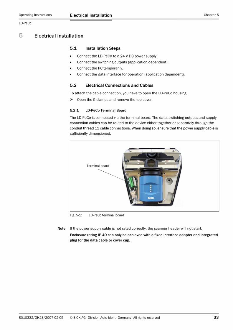
5.2.1 LD-PeCo Terminal Board
The LD-PeCo is connected via the terminal board. The data, switching outputs and supply connection cables can be routed to the device either together or separately through the conduit thread 11 cable connections. When doing so, ensure that the power supply cable is sufficiently dimensioned.
Note If the power supply cable is not rated correctly, the scanner header will not start.
Enclosure rating IP 40 can only be achieved with a fixed interface adapter and integrated plug for the data cable or cover cap.
Fig. 5-1: LD-PeCo terminal board
Terminal board
Chapter 5 Operating Instructions
LD-PeCo People Counter
34 © SICK AG · Division Auto Ident · Germany · All rights reserved 8010332/QH23/2007-02-05
Electrical installation
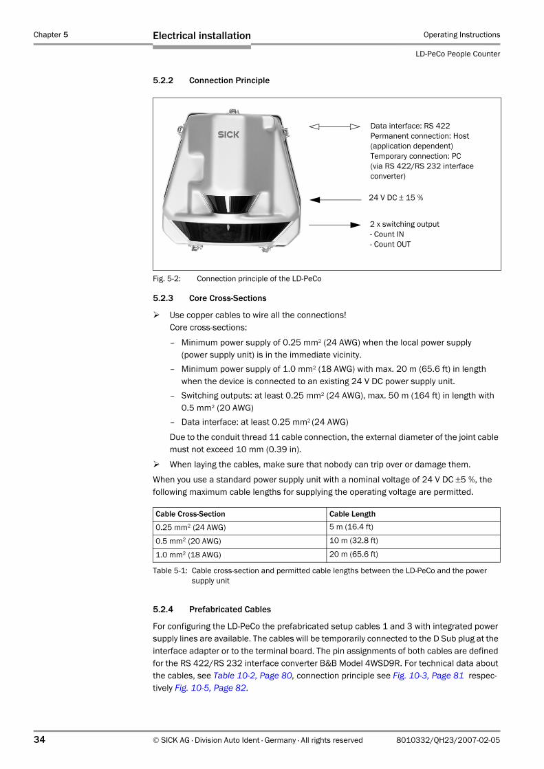
5.2.2 Connection Principle
5.2.3 Core Cross-Sections
Use copper cables to wire all the connections!Core cross-sections:
– Minimum power supply of 0.25 mm2 (24 AWG) when the local power supply (power supply unit) is in the immediate vicinity.
– Minimum power supply of 1.0 mm2 (18 AWG) with max. 20 m (65.6 ft) in length when the device is connected to an existing 24 V DC power supply unit.
– Switching outputs: at least 0.25 mm2 (24 AWG), max. 50 m (164 ft) in length with 0.5 mm2 (20 AWG)
– Data interface: at least 0.25 mm2 (24 AWG)
Due to the conduit thread 11 cable connection, the external diameter of the joint cable must not exceed 10 mm (0.39 in).
When laying the cables, make sure that nobody can trip over or damage them.
When you use a standard power supply unit with a nominal voltage of 24 V DC ±5 %, the following maximum cable lengths for supplying the operating voltage are permitted.
5.2.4 Prefabricated Cables
For configuring the LD-PeCo the prefabricated setup cables 1 and 3 with integrated power supply lines are available. The cables will be temporarily connected to the D Sub plug at the interface adapter or to the terminal board. The pin assignments of both cables are defined for the RS 422/RS 232 interface converter B&B Model 4WSD9R. For technical data about the cables, see Table 10-2, Page 80, connection principle see Fig. 10-3, Page 81 respec-tively Fig. 10-5, Page 82.
Fig. 5-2: Connection principle of the LD-PeCo
Cable Cross-Section Cable Length
0.25 mm2 (24 AWG) 5 m (16.4 ft)
0.5 mm2 (20 AWG) 10 m (32.8 ft)
1.0 mm2 (18 AWG) 20 m (65.6 ft)
Table 5-1: Cable cross-section and permitted cable lengths between the LD-PeCo and the power supply unit
24 V DC ± 15 %
2 x switching output - Count IN- Count OUT
Data interface: RS 422Permanent connection: Host(application dependent)Temporary connection: PC(via RS 422/RS 232 interface converter)
Operating Instructions Chapter 5
LD-PeCo
Electrical installation
8010332/QH23/2007-02-05 © SICK AG · Division Auto Ident · Germany · All rights reserved 35
5.3 Pin Assignment of the Connections
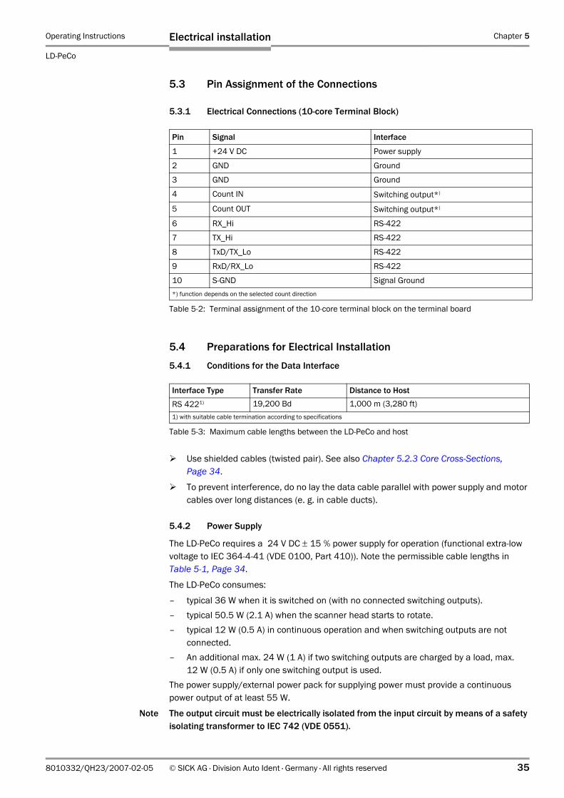
5.3.1 Electrical Connections (10-core Terminal Block)
5.4 Preparations for Electrical Installation
5.4.1 Conditions for the Data Interface
Use shielded cables (twisted pair). See also Chapter 5.2.3 Core Cross-Sections, Page 34.
To prevent interference, do no lay the data cable parallel with power supply and motor cables over long distances (e. g. in cable ducts).
5.4.2 Power Supply
The LD-PeCo requires a 24 V DC ± 15 % power supply for operation (functional extra-low voltage to IEC 364-4-41 (VDE 0100, Part 410)). Note the permissible cable lengths in Table 5-1, Page 34.
The LD-PeCo consumes:
– typical 36 W when it is switched on (with no connected switching outputs).– typical 50.5 W (2.1 A) when the scanner head starts to rotate.– typical 12 W (0.5 A) in continuous operation and when switching outputs are not
connected.– An additional max. 24 W (1 A) if two switching outputs are charged by a load, max.
12 W (0.5 A) if only one switching output is used.The power supply/external power pack for supplying power must provide a continuous power output of at least 55 W.
Note The output circuit must be electrically isolated from the input circuit by means of a safety isolating transformer to IEC 742 (VDE 0551).
Pin Signal Interface
1 +24 V DC Power supply
2 GND Ground
3 GND Ground
4 Count IN Switching output*)
5 Count OUT Switching output*)
6 RX_Hi RS-422
7 TX_Hi RS-422
8 TxD/TX_Lo RS-422
9 RxD/RX_Lo RS-422
10 S-GND Signal Ground*) function depends on the selected count direction
Table 5-2: Terminal assignment of the 10-core terminal block on the terminal board
Interface Type Transfer Rate Distance to Host
RS 4221) 19,200 Bd 1,000 m (3,280 ft)1) with suitable cable termination according to specifications
Table 5-3: Maximum cable lengths between the LD-PeCo and host
Chapter 5 Operating Instructions
LD-PeCo People Counter
36 © SICK AG · Division Auto Ident · Germany · All rights reserved 8010332/QH23/2007-02-05
Electrical installation
5.5 Carrying Out Electrical Installation
5.5.1 Tools
• Tool• Digital measuring device (current/voltage measurement)
5.5.2 Connecting the Power Supply
Make sure that the power supply to the LD-PeCo is switched off.
Open the 5 clamps on the housing and remove the top cover.
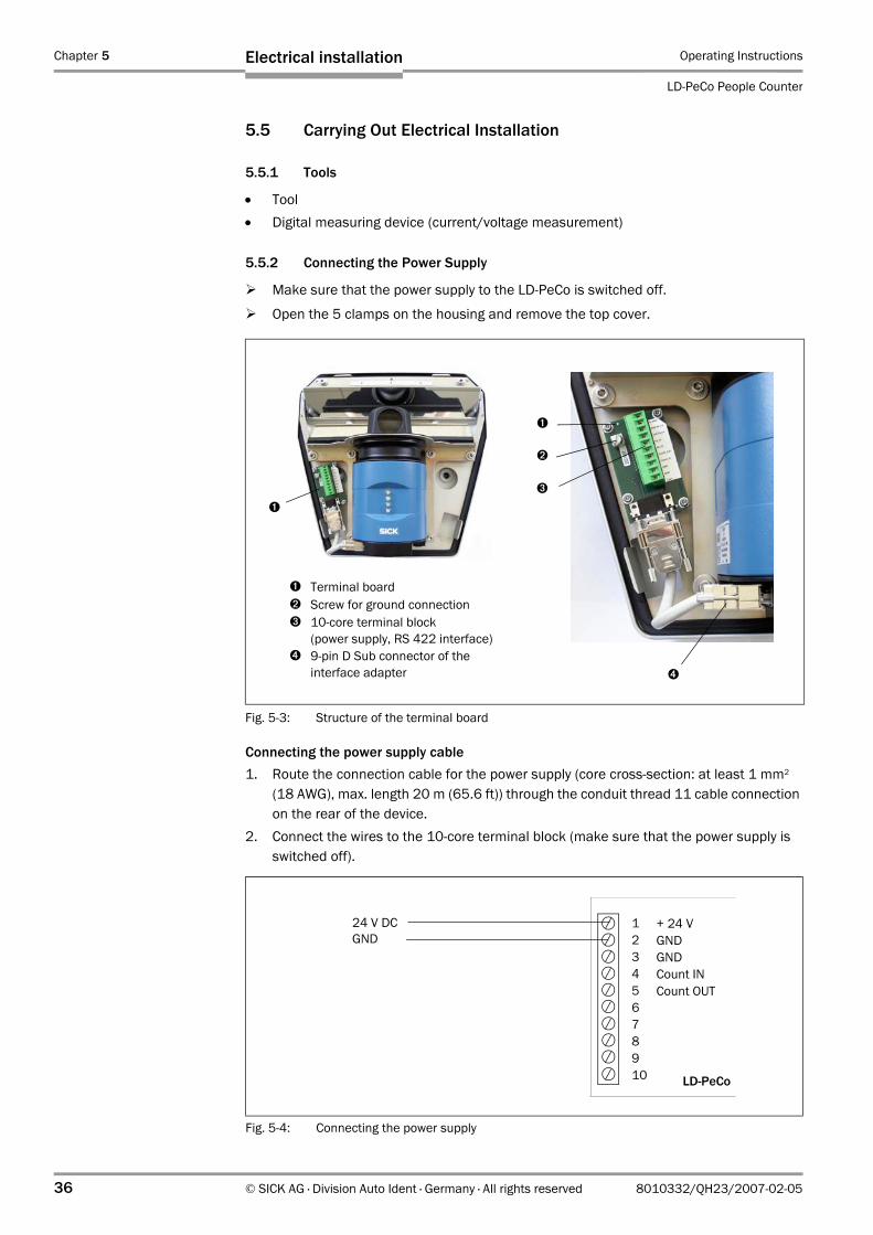
Connecting the power supply cable1. Route the connection cable for the power supply (core cross-section: at least 1 mm2
(18 AWG), max. length 20 m (65.6 ft)) through the conduit thread 11 cable connection on the rear of the device.
2. Connect the wires to the 10-core terminal block (make sure that the power supply is switched off).
Fig. 5-3: Structure of the terminal board
➊
➋
➍
➊ Terminal board➋ Screw for ground connection➌ 10-core terminal block
(power supply, RS 422 interface)➍ 9-pin D Sub connector of the
interface adapter
➊
➌
Fig. 5-4: Connecting the power supply
+ 24 VGNDGNDCount INCount OUT
LD-PeCo
12345678910
24 V DCGND
Operating Instructions Chapter 5
LD-PeCo
Electrical installation
8010332/QH23/2007-02-05 © SICK AG · Division Auto Ident · Germany · All rights reserved 37
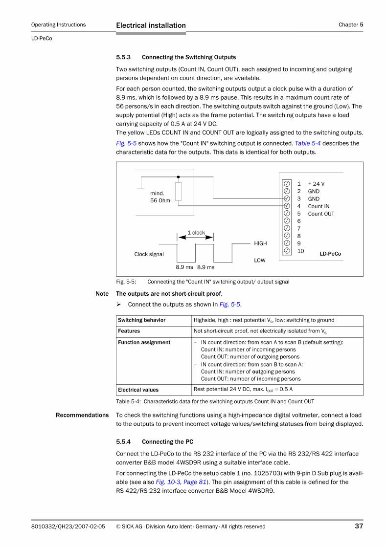
5.5.3 Connecting the Switching Outputs
Two switching outputs (Count IN, Count OUT), each assigned to incoming and outgoing persons dependent on count direction, are available.
For each person counted, the switching outputs output a clock pulse with a duration of 8.9 ms, which is followed by a 8.9 ms pause. This results in a maximum count rate of 56 persons/s in each direction. The switching outputs switch against the ground (Low). The supply potential (High) acts as the frame potential. The switching outputs have a load carrying capacity of 0.5 A at 24 V DC.The yellow LEDs COUNT IN and COUNT OUT are logically assigned to the switching outputs.
Fig. 5-5 shows how the "Count IN" switching output is connected. Table 5-4 describes the characteristic data for the outputs. This data is identical for both outputs.
Note The outputs are not short-circuit proof.
Connect the outputs as shown in Fig. 5-5.
Recommendations To check the switching functions using a high-impedance digital voltmeter, connect a load to the outputs to prevent incorrect voltage values/switching statuses from being displayed.
5.5.4 Connecting the PC
Connect the LD-PeCo to the RS 232 interface of the PC via the RS 232/RS 422 interface converter B&B model 4WSD9R using a suitable interface cable.
For connecting the LD-PeCo the setup cable 1 (no. 1025703) with 9-pin D Sub plug is avail-able (see also Fig. 10-3, Page 81). The pin assignment of this cable is defined for the RS 422/RS 232 interface converter B&B Model 4WSDR9.
Fig. 5-5: Connecting the "Count IN" switching output/ output signal
+ 24 VGNDGNDCount INCount OUT
LD-PeCo
12345678910
mind. 56 Ohm
8.9 ms
Clock signal
8.9 ms
HIGH
LOW
1 clock
Switching behavior Highside, high : rest potential VS, low: switching to ground
Features Not short-circuit proof, not electrically isolated from Vs
Function assignment – IN count direction: from scan A to scan B (default setting):Count IN: number of incoming personsCount OUT: number of outgoing persons
– IN count direction: from scan B to scan A:Count IN: number of outgoing personsCount OUT: number of incoming persons
Electrical values Rest potential 24 V DC, max. IOUT = 0.5 A
Table 5-4: Characteristic data for the switching outputs Count IN and Count OUT
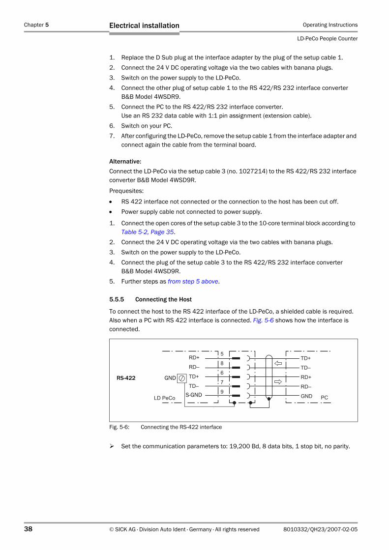
Chapter 5 Operating Instructions
LD-PeCo People Counter
38 © SICK AG · Division Auto Ident · Germany · All rights reserved 8010332/QH23/2007-02-05
Electrical installation
1. Replace the D Sub plug at the interface adapter by the plug of the setup cable 1.2. Connect the 24 V DC operating voltage via the two cables with banana plugs.3. Switch on the power supply to the LD-PeCo.4. Connect the other plug of setup cable 1 to the RS 422/RS 232 interface converter
B&B Model 4WSDR9.5. Connect the PC to the RS 422/RS 232 interface converter.
Use an RS 232 data cable with 1:1 pin assignment (extension cable). 6. Switch on your PC.7. After configuring the LD-PeCo, remove the setup cable 1 from the interface adapter and
connect again the cable from the terminal board.
Alternative:Connect the LD-PeCo via the setup cable 3 (no. 1027214) to the RS 422/RS 232 interface converter B&B Model 4WSD9R.
Prequesites:
• RS 422 interface not connected or the connection to the host has been cut off. • Power supply cable not connected to power supply.
1. Connect the open cores of the setup cable 3 to the 10-core terminal block according to Table 5-2, Page 35.
2. Connect the 24 V DC operating voltage via the two cables with banana plugs.3. Switch on the power supply to the LD-PeCo.4. Connect the plug of the setup cable 3 to the RS 422/RS 232 interface converter
B&B Model 4WSD9R.5. Further steps as from step 5 above.
5.5.5 Connecting the Host
To connect the host to the RS 422 interface of the LD-PeCo, a shielded cable is required. Also when a PC with RS 422 interface is connected. Fig. 5-6 shows how the interface is connected.
Set the communication parameters to: 19,200 Bd, 8 data bits, 1 stop bit, no parity.
Fig. 5-6: Connecting the RS-422 interface
���
���
���
���
���
���
���
���
���
���
�
�
� ���� ���
RS-422 GND
S-GND
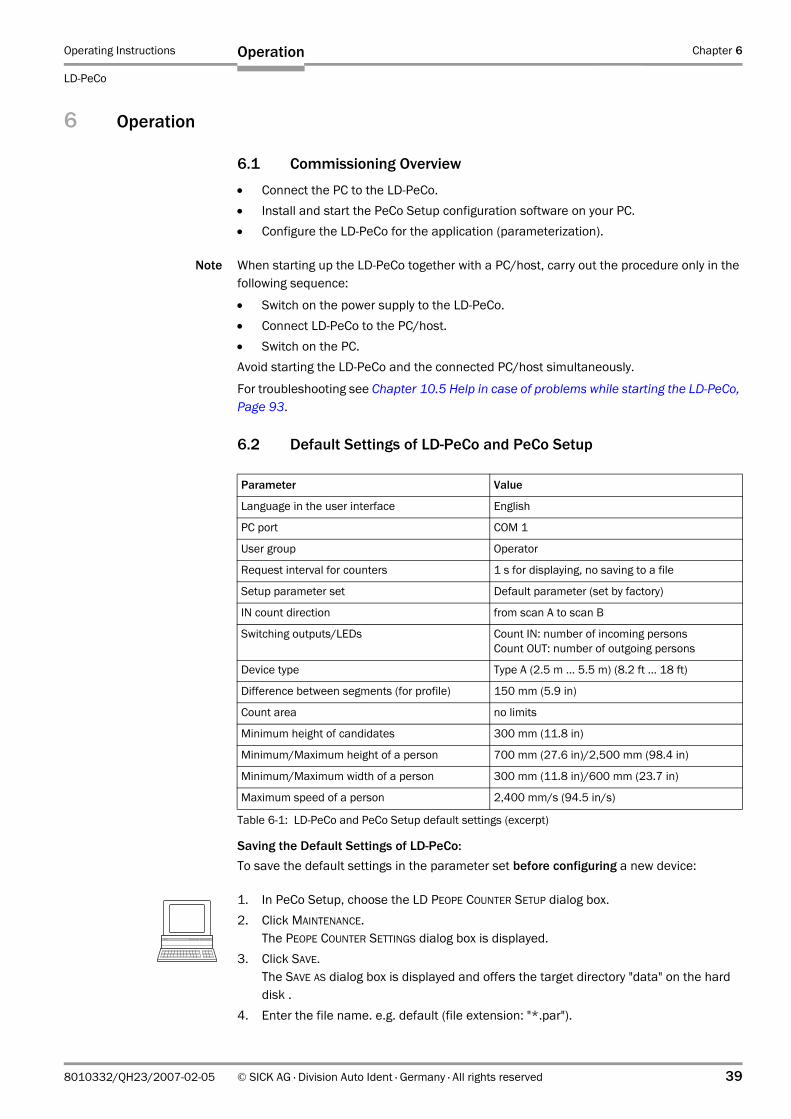
Operating Instructions Chapter 6
LD-PeCo
Operation
8010332/QH23/2007-02-05 © SICK AG · Division Auto Ident · Germany · All rights reserved 39
6 Operation
6.1 Commissioning Overview
• Connect the PC to the LD-PeCo. • Install and start the PeCo Setup configuration software on your PC.• Configure the LD-PeCo for the application (parameterization).
Note When starting up the LD-PeCo together with a PC/host, carry out the procedure only in the following sequence:
• Switch on the power supply to the LD-PeCo.• Connect LD-PeCo to the PC/host.• Switch on the PC. Avoid starting the LD-PeCo and the connected PC/host simultaneously.
For troubleshooting see Chapter 10.5 Help in case of problems while starting the LD-PeCo, Page 93.
6.2 Default Settings of LD-PeCo and PeCo Setup
Saving the Default Settings of LD-PeCo:To save the default settings in the parameter set before configuring a new device:
1. In PeCo Setup, choose the LD PEOPE COUNTER SETUP dialog box.2. Click MAINTENANCE.
The PEOPE COUNTER SETTINGS dialog box is displayed.3. Click SAVE.
The SAVE AS dialog box is displayed and offers the target directory "data" on the hard disk .
4. Enter the file name. e.g. default (file extension: "*.par").
Parameter Value
Language in the user interface English
PC port COM 1
User group Operator
Request interval for counters 1 s for displaying, no saving to a file
Setup parameter set Default parameter (set by factory)
IN count direction from scan A to scan B
Switching outputs/LEDs Count IN: number of incoming persons Count OUT: number of outgoing persons
Device type Type A (2.5 m ... 5.5 m) (8.2 ft ... 18 ft)
Difference between segments (for profile) 150 mm (5.9 in)
Count area no limits
Minimum height of candidates 300 mm (11.8 in)
Minimum/Maximum height of a person 700 mm (27.6 in)/2,500 mm (98.4 in)
Minimum/Maximum width of a person 300 mm (11.8 in)/600 mm (23.7 in)
Maximum speed of a person 2,400 mm/s (94.5 in/s)
Table 6-1: LD-PeCo and PeCo Setup default settings (excerpt)
Chapter 6 Operating Instructions
LD-PeCo People Counter
40 © SICK AG · Division Auto Ident · Germany · All rights reserved 8010332/QH23/2007-02-05
Operation
5. Press SAVE to confirm your selection. The LD-PeCo default settings are saved in the target directory "data" under "PeCoSetup".
6.3 Quick-Start
Note To setup the LD-PeCo, a PC must be connected. (see Chapter 5.5.4 Connecting the PC, Page 37).
6.3.1 Starting Up LD-PeCo with the Default Factory Settings
1. Open the LD-PeCo housing. To do so, loosen the five clamps on the cover.2. Replace the D Sub plug at the interface adapter by the plug of the setup cable 1.
The pin assignment of this cable is defined for the RS 422/RS 232 interface converter B&B Model 4WSDR9.
3. Connect the 24 V DC operating voltage via the two cables with banana plugs.4. Switch on the power supply to the LD-PeCo.
The LD-PeCo starts after it has carried out a self-test. The green LED flashes. The scanner head starts to rotate. The LD-PeCo does not start counting immediately because the area sounding its field of vision first has to be taught in.
5. Connect the other plug of setup cable 1 to the RS 422/RS 232 interface converter B&B Model 4WSDR9.
6. Connect the PC to the RS 422/RS 232 interface converter.Use an RS 232 data cable with 1:1 pin assignment (extension cable).
7. Switch on your PC and start WindowsTM (minimum requirement: Windows 95TM)8. Install the CD-ROM-based PeCo Setup configuration software supplied on the PC. 9. Start the PeCo Setup user interface.
The PROGRAMM SETTING dialog box is displayed.10. Choose the required language and PC port.
Click OK.The LD PEOPLE COUNTER SETUP dialog box is displayed.
11. Click SETUP. PeCo Setup establishes a connection to the LD-PeCo.
12. Follow the instructions in the dialog boxes. 13. In the STEP 3 dialog box click the flashing LEARN OUTLINE button.14. Follow the instructions in the further dialog boxes.15. In the STEP 6 dialog box click SEND PARAMETERS AND START COUNTING.
The READY. THE PEOPLE COUNTER IS COUNTING dialog box is displayed and shows continuously the count results.
16. If persons now completely pass through the light curtains of both scan beams in one of both directions, the LD-PeCo will detect and count them. For each person counted and depending on their direction of movement, the switching outputs Count IN and Count OUT output a pulse.The two yellow LEDs light up briefly when the corresponding switching output is active.
17. Save the parameter set as a configuration file (".par“) to the proposed directory "data" or an other target directory on then hard disk.
The LD-PeCo is ready for operation.
If switched on again, the LD-PeCo will automatically start in count mode.
Operating Instructions Chapter 6
LD-PeCo
Operation
8010332/QH23/2007-02-05 © SICK AG · Division Auto Ident · Germany · All rights reserved 41
6.4 Configuration (Parameterization)
The LD-PeCo is configured locally in accordance with the on-site requirements using the PeCo Setup configuration software. The basis are the factory default settings or an existing application-specific LD-PeCo parameter set.
6.4.1 Configuring LD-PeCo with the PeCo Setup User Interface
To use the PeCo Setup software, a PC with the software installed must be connected. Chapter 5.5.4 Connecting the PC, Page 37 describes the procedure for connecting the PC to the LD-PeCo. The following section explains how to install the PeCo Setup software and operate the user interface.
6.4.2 Installing the PeCo Setup Software
The PeCo Setup configuration software is supplied on CD-ROM with the LD-PeCo. To use the software, you need a PC with an 80486 processor or higher, 66 MHz, 16 MB RAM, CD-ROM drive, serial interface and mouse, as well as one of the following operating systems: Windows 95TM/98TM, Windows NT4.0TM, Windows 2000TM, or Windows XPTM. Approx. 7.5 MB of hard disk space is required to install PeCo Setup.
The latest software version can be downloaded from www.sick.com.
Installation Preparations
1. Insert the CD-ROM.2. Connect the LD-PeCo to the power supply
(see Chapter 5 Electrical installation, Page 33).3. Switch on the power supply to the LD-PeCo.
The scanner head starts to rotate.4. Switch on your PC and start Windows.5. Connect the PC to the LD-PeCo using a data connection cable
(see Chapter 5.5.4 Connecting the PC, Page 37).Note The section below explains how to install the program on Windows 98TM.
Installing the SoftwareWhen you install PeCo Setup, the installation program creates the main PeCo Setup directory along with the required links.
1. Close all Windows applications.2. Insert the CD-ROM in your CD drive
(the autorun function for programs must be activated).3. Confirm the "PeCo SETUP VERSION 1.1 - SETUP" with "OK".
The installation program is started and guides you step by step through the installation procedure.
4. Confirm the installation with "OK".5. Restart your PC.
The "PeCo Setup" application is installed and ready for use.
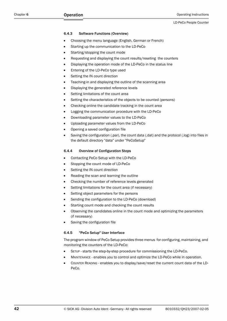
Chapter 6 Operating Instructions
LD-PeCo People Counter
42 © SICK AG · Division Auto Ident · Germany · All rights reserved 8010332/QH23/2007-02-05
Operation
6.4.3 Software Functions (Overview)
• Choosing the menu language (English, German or French)• Starting up the communication to the LD-PeCo• Starting/stopping the count mode• Requesting and displaying the count results/reseting the counters• Displaying the operation mode of the LD-PeCo in the status line• Entering of the LD-PeCo type used• Setting the IN count direction• Teaching-in and displaying the outline of the scanning area• Displaying the generated reference levels• Setting limitations of the count area• Setting the characteristics of the objects to be counted (persons)• Checking online the candidate tracking in the count area• Logging the communication procedure with the LD-PeCo• Downloading parameter values to the LD-PeCo• Uploading parameter values from the LD-PeCo• Opening a saved configuration file• Saving the configuration (.par), the count data (.dat) and the protocol (.log) into files in
the default directory "data" under "PeCoSetup"
6.4.4 Overview of Configuration Steps
• Contacting PeCo Setup with the LD-PeCo• Stopping the count mode of LD-PeCo• Setting the IN count direction• Reading the scan and learning the outline• Checking the number of reference levels generated• Setting limitations for the count area (if necessary)• Setting object parameters for the persons• Sending the configuration to the LD-PeCo (download)• Starting count mode and checking the count results• Observing the candidates online in the count mode and optimizing the parameters
(if necessary)• Saving the configuration file
6.4.5 "PeCo Setup" User Interface
The program window of PeCo Setup provides three menus for configuring, maintaining, and monitoring the counters of the LD-PeCo:
• SETUP - starts the step-by-step procedure for commissioning the LD-PeCo.• MAINTENANCE - enables you to control and optimize the LD-PeCo while in operation.• COUNTER READING - enables you to display/save/reset the current count data of the LD-
PeCo.
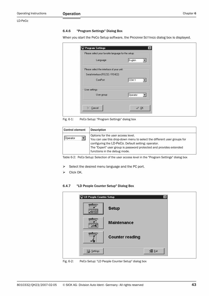
Operating Instructions Chapter 6
LD-PeCo
Operation
8010332/QH23/2007-02-05 © SICK AG · Division Auto Ident · Germany · All rights reserved 43
6.4.6 "Program Settings" Dialog Box
When you start the PeCo Setup software, the PROGRAM SETTINGS dialog box is displayed.
Select the desired menu language and the PC port.
Click OK.
6.4.7 "LD People Counter Setup" Dialog Box
Fig. 6-1: PeCo Setup: "Program Settings" dialog box
Control element Description
Options for the user access level.You can use this drop-down menu to select the different user groups for configuring the LD-PeCo. Default setting: operator. The "Expert" user group is password protected and provides extended functions in the debug mode.
Table 6-2: PeCo Setup: Selection of the user access level in the "Program Settings" dialog box
Fig. 6-2: PeCo Setup: "LD People Counter Setup" dialog box
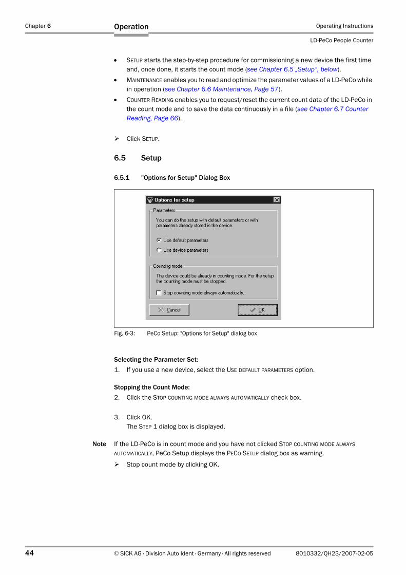
Chapter 6 Operating Instructions
LD-PeCo People Counter
44 © SICK AG · Division Auto Ident · Germany · All rights reserved 8010332/QH23/2007-02-05
Operation
• SETUP starts the step-by-step procedure for commissioning a new device the first timeand, once done, it starts the count mode (see Chapter 6.5 „Setup“, below).
• MAINTENANCE enables you to read and optimize the parameter values of a LD-PeCo while in operation (see Chapter 6.6 Maintenance, Page 57).
• COUNTER READING enables you to request/reset the current count data of the LD-PeCo in the count mode and to save the data continuously in a file (see Chapter 6.7 Counter Reading, Page 66).
Click SETUP.
6.5 Setup
6.5.1 "Options for Setup" Dialog Box
Selecting the Parameter Set:1. If you use a new device, select the USE DEFAULT PARAMETERS option.
Stopping the Count Mode:2. Click the STOP COUNTING MODE ALWAYS AUTOMATICALLY check box.
3. Click OK.The STEP 1 dialog box is displayed.
Note If the LD-PeCo is in count mode and you have not clicked STOP COUNTING MODE ALWAYS AUTOMATICALLY, PeCo Setup displays the PECO SETUP dialog box as warning.
Stop count mode by clicking OK.
Fig. 6-3: PeCo Setup: "Options for Setup" dialog box
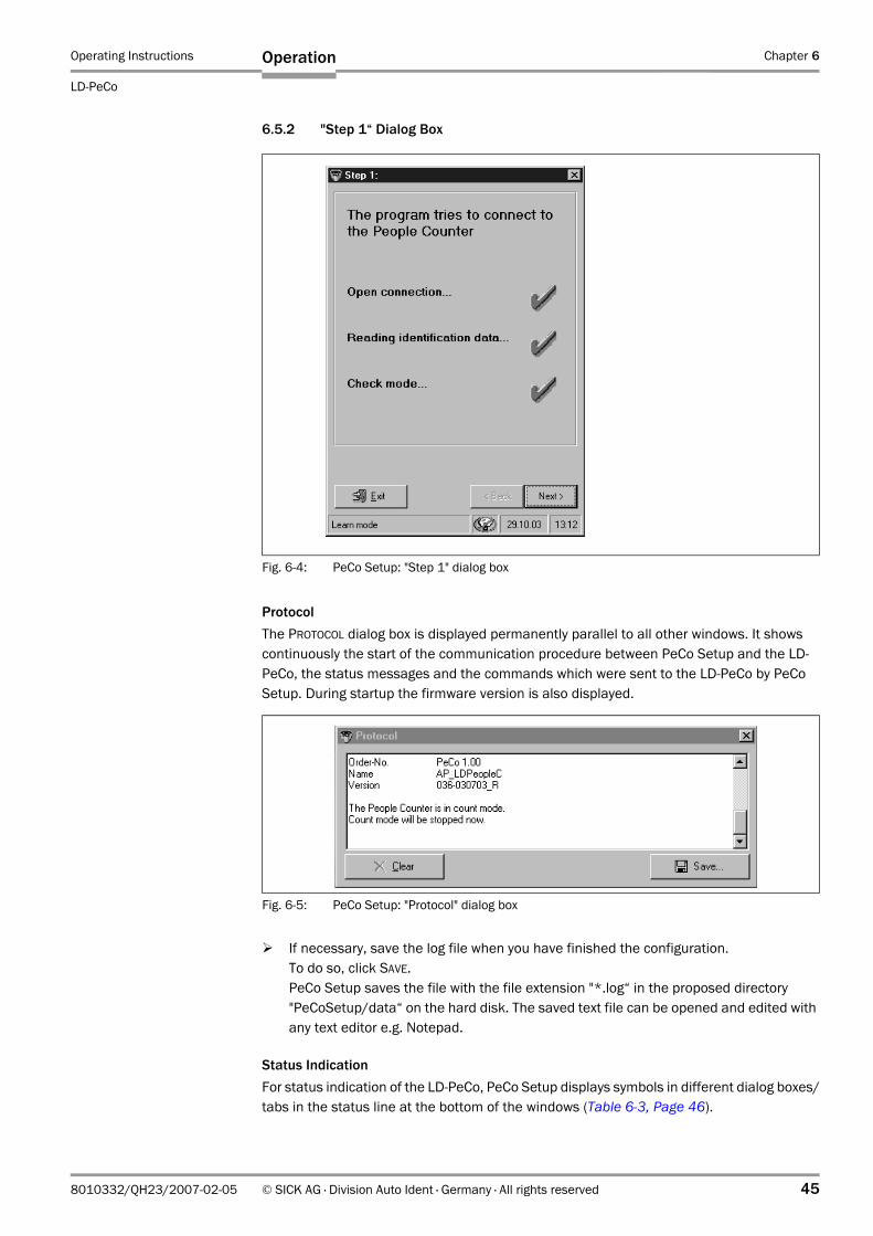
Operating Instructions Chapter 6
LD-PeCo
Operation
8010332/QH23/2007-02-05 © SICK AG · Division Auto Ident · Germany · All rights reserved 45
6.5.2 "Step 1“ Dialog Box
ProtocolThe PROTOCOL dialog box is displayed permanently parallel to all other windows. It shows continuously the start of the communication procedure between PeCo Setup and the LD-PeCo, the status messages and the commands which were sent to the LD-PeCo by PeCo Setup. During startup the firmware version is also displayed.
If necessary, save the log file when you have finished the configuration. To do so, click SAVE. PeCo Setup saves the file with the file extension "*.log“ in the proposed directory "PeCoSetup/data“ on the hard disk. The saved text file can be opened and edited with any text editor e.g. Notepad.
Status IndicationFor status indication of the LD-PeCo, PeCo Setup displays symbols in different dialog boxes/tabs in the status line at the bottom of the windows (Table 6-3, Page 46).
Fig. 6-4: PeCo Setup: "Step 1" dialog box
Fig. 6-5: PeCo Setup: "Protocol" dialog box
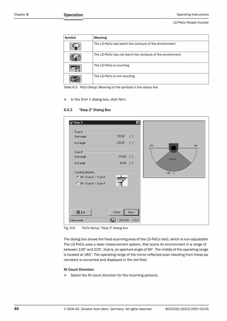
Chapter 6 Operating Instructions
LD-PeCo People Counter
46 © SICK AG · Division Auto Ident · Germany · All rights reserved 8010332/QH23/2007-02-05
Operation
In the STEP 1 dialog box, click NEXT.
6.5.3 "Step 2" Dialog Box
The dialog box shows the fixed scanning area of the LD-PeCo (red), which is non-adjustable.The LD-PeCo uses a laser measurement system, that scans its environment in a range of between 135° and 225°, that is, an aperture angle of 90°. The middle of the operating range is located at 180°. The operating range of the mirror-reflected scan resulting from these pa-rameters is converted and displayed in the red field.
IN Count Direction:Select the IN count direction for the incoming persons.
Symbol Meaning
The LD-PeCo has learnt the contours of the environment.
The LD-PeCo has not learnt the contours of the environment.
The LD-PeCo is counting.
The LD-PeCo is not counting.
Table 6-3: PeCo Setup: Meaning of the symbols in the status line
Fig. 6-6: PeCo Setup: "Step 2" dialog box
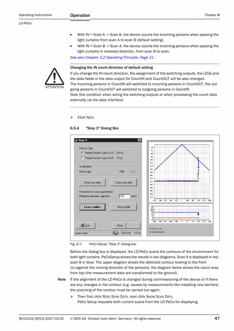
Operating Instructions Chapter 6
LD-PeCo
Operation
8010332/QH23/2007-02-05 © SICK AG · Division Auto Ident · Germany · All rights reserved 47
• With IN = Scan A -> Scan B, the device counts the incoming persons when passing the light curtains from scan A to scan B (default setting).
• With IN = Scan B -> Scan A, the device counts the incoming persons when passing the light curtains in reversed direction, from scan B to scan.
See also Chapter 3.2 Operating Principle, Page 21 .
Changing the IN count direction of default settingIf you change the IN count direction, the assignment of the switching outputs, the LEDs and the data fields in the data output for CountIN and CountOUT will be also changed.The incoming persons in CountIN will switched to incoming persons in CountOUT, the out-going persons in CountOUT will switched to outgoing persons in CountIN.Note this condition when wiring the switching outputs or when processing the count data externally via the data interface!
Click NEXT.
6.5.4 "Step 3" Dialog Box
Before the dialog box is displayed, the LD-PeCo scans the contours of the environment for both light curtains. PeCoSetup shows the results in two diagrams. Scan A is displayed in red, scan B in blue. The upper diagram shows the detected contour looking to the front (in/against the moving direction of the persons), the diagram below shows the count area from top (the measurement data are transformed to the ground).
Note If the alignment of the LD-PeCo is changed during commissioning of the device or if there are any changes in the contour (e.g. causes by measurements like installing new barriers) the scanning of the contour must be carried out again.
Then first click READ SCAN DATA, next click SHOW SCAN DATA.PeCo Setup requests both current scans from the LD-PeCo for displaying.
Fig. 6-7: PeCo Setup: "Step 3" dialog box
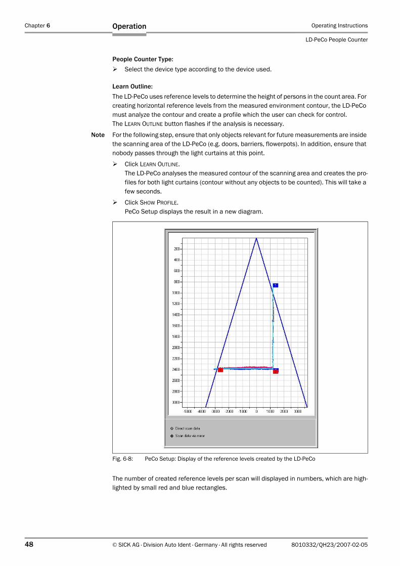
Chapter 6 Operating Instructions
LD-PeCo People Counter
48 © SICK AG · Division Auto Ident · Germany · All rights reserved 8010332/QH23/2007-02-05
Operation
People Counter Type:Select the device type according to the device used.
Learn Outline:The LD-PeCo uses reference levels to determine the height of persons in the count area. For creating horizontal reference levels from the measured environment contour, the LD-PeCo must analyze the contour and create a profile which the user can check for control. The LEARN OUTLINE button flashes if the analysis is necessary.
Note For the following step, ensure that only objects relevant for future measurements are inside the scanning area of the LD-PeCo (e.g. doors, barriers, flowerpots). In addition, ensure that nobody passes through the light curtains at this point.
Click LEARN OUTLINE.The LD-PeCo analyses the measured contour of the scanning area and creates the pro-files for both light curtains (contour without any objects to be counted). This will take a few seconds.
Click SHOW PROFILE.PeCo Setup displays the result in a new diagram.
The number of created reference levels per scan will displayed in numbers, which are high-lighted by small red and blue rectangles.
Fig. 6-8: PeCo Setup: Display of the reference levels created by the LD-PeCo
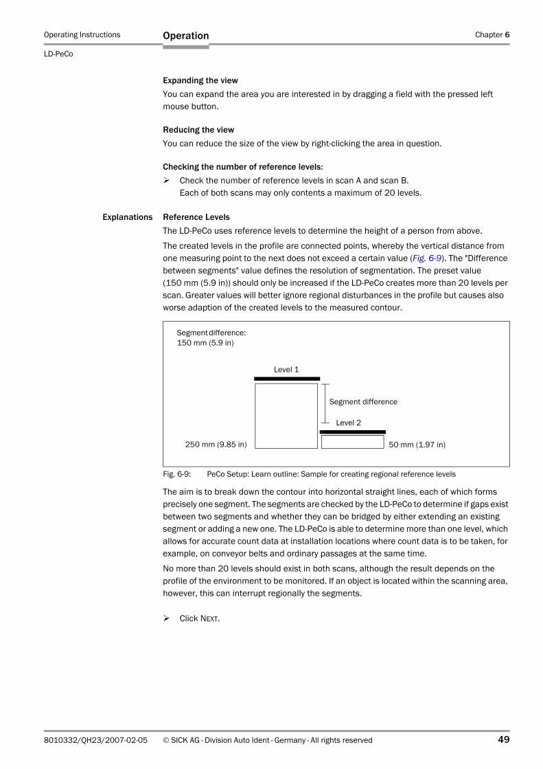
Operating Instructions Chapter 6
LD-PeCo
Operation
8010332/QH23/2007-02-05 © SICK AG · Division Auto Ident · Germany · All rights reserved 49
Expanding the viewYou can expand the area you are interested in by dragging a field with the pressed left mouse button.
Reducing the viewYou can reduce the size of the view by right-clicking the area in question.
Checking the number of reference levels:Check the number of reference levels in scan A and scan B. Each of both scans may only contents a maximum of 20 levels.
Explanations Reference LevelsThe LD-PeCo uses reference levels to determine the height of a person from above.
The created levels in the profile are connected points, whereby the vertical distance from one measuring point to the next does not exceed a certain value (Fig. 6-9). The "Difference between segments" value defines the resolution of segmentation. The preset value (150 mm (5.9 in)) should only be increased if the LD-PeCo creates more than 20 levels per scan. Greater values will better ignore regional disturbances in the profile but causes also worse adaption of the created levels to the measured contour.
The aim is to break down the contour into horizontal straight lines, each of which forms precisely one segment. The segments are checked by the LD-PeCo to determine if gaps exist between two segments and whether they can be bridged by either extending an existing segment or adding a new one. The LD-PeCo is able to determine more than one level, which allows for accurate count data at installation locations where count data is to be taken, for example, on conveyor belts and ordinary passages at the same time.
No more than 20 levels should exist in both scans, although the result depends on the profile of the environment to be monitored. If an object is located within the scanning area, however, this can interrupt regionally the segments.
Click NEXT.
Fig. 6-9: PeCo Setup: Learn outline: Sample for creating regional reference levels
50 mm (1.97 in)
Segment difference: 150 mm (5.9 in)
250 mm (9.85 in)
Level 1
Level 2
Segment difference
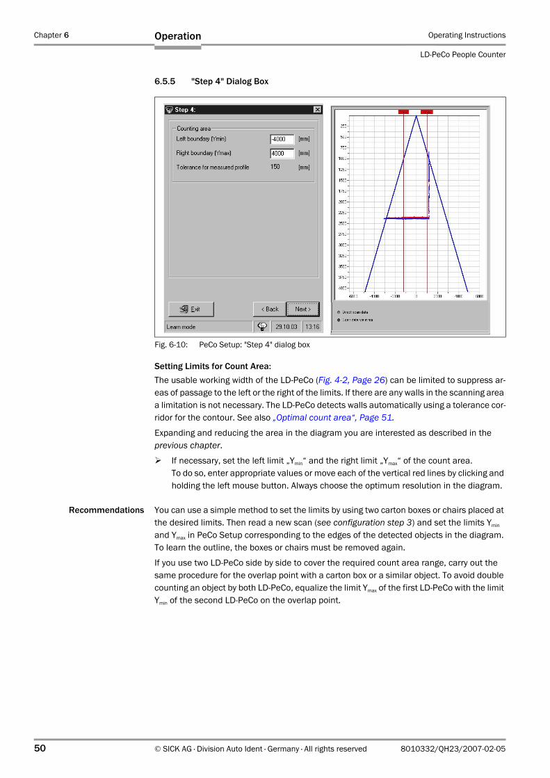
Chapter 6 Operating Instructions
LD-PeCo People Counter
50 © SICK AG · Division Auto Ident · Germany · All rights reserved 8010332/QH23/2007-02-05
Operation
6.5.5 "Step 4" Dialog Box
Setting Limits for Count Area:The usable working width of the LD-PeCo (Fig. 4-2, Page 26) can be limited to suppress ar-eas of passage to the left or the right of the limits. If there are any walls in the scanning area a limitation is not necessary. The LD-PeCo detects walls automatically using a tolerance cor-ridor for the contour. See also „Optimal count area“, Page 51.
Expanding and reducing the area in the diagram you are interested as described in the previous chapter.
If necessary, set the left limit „Ymin“ and the right limit „Ymax“ of the count area.To do so, enter appropriate values or move each of the vertical red lines by clicking and holding the left mouse button. Always choose the optimum resolution in the diagram.
Recommendations You can use a simple method to set the limits by using two carton boxes or chairs placed at the desired limits. Then read a new scan (see configuration step 3) and set the limits Ymin and Ymax in PeCo Setup corresponding to the edges of the detected objects in the diagram. To learn the outline, the boxes or chairs must be removed again.
If you use two LD-PeCo side by side to cover the required count area range, carry out the same procedure for the overlap point with a carton box or a similar object. To avoid double counting an object by both LD-PeCo, equalize the limit Ymax of the first LD-PeCo with the limit Ymin of the second LD-PeCo on the overlap point.
Fig. 6-10: PeCo Setup: "Step 4" dialog box
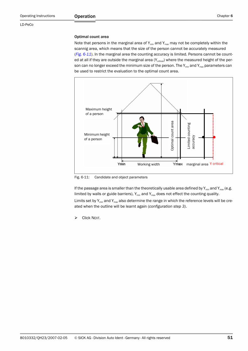
Operating Instructions Chapter 6
LD-PeCo
Operation
8010332/QH23/2007-02-05 © SICK AG · Division Auto Ident · Germany · All rights reserved 51
Optimal count areaNote that persons in the marginal area of Ymin and Ymax may not be completely within the scannig area, which means that the size of the person cannot be accurately measured (Fig. 6-11). In the marginal area the counting accuracy is limited. Persons cannot be count-ed at all if they are outside the marginal area (Ycritical) where the measured height of the per-son can no longer exceed the minimum size of the person. The Ymin and Ymax parameters can be used to restrict the evaluation to the optimal count area.
If the passage area is smaller than the theoretically usable area defined by Ymin and Ymax (e.g. limited by walls or guide barriers), Ymin and Ymax does not effect the counting quality.
Limits set by Ymin and Ymax also determine the range in which the reference levels will be cre-ated when the outline will be learnt again (configuration step 3).
Click NEXT.
Fig. 6-11: Candidate and object parameters
Working width
Maximum height of a person
Minimum height of a person
Lim
ited
coun
ting
accu
racy
Optim
al c
ount
are
a
marginal area YkritischY critical
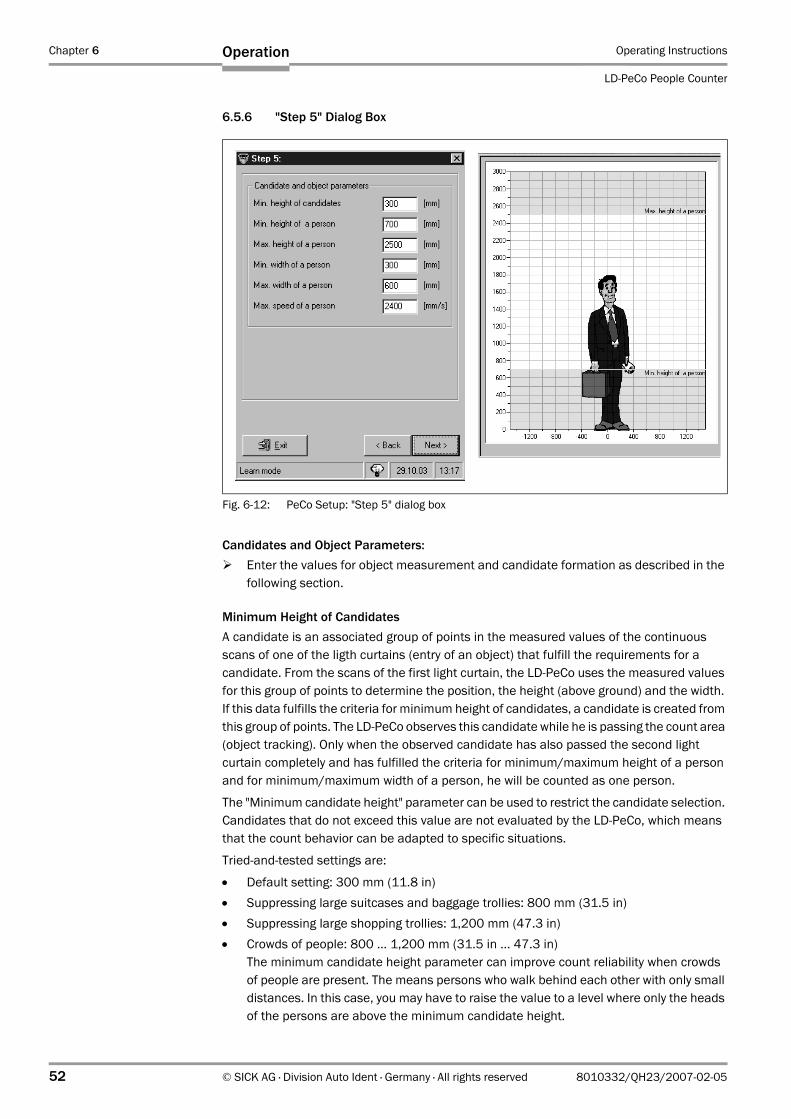
Chapter 6 Operating Instructions
LD-PeCo People Counter
52 © SICK AG · Division Auto Ident · Germany · All rights reserved 8010332/QH23/2007-02-05
Operation
6.5.6 "Step 5" Dialog Box
Candidates and Object Parameters:Enter the values for object measurement and candidate formation as described in the following section.
Minimum Height of Candidates A candidate is an associated group of points in the measured values of the continuous scans of one of the ligth curtains (entry of an object) that fulfill the requirements for a candidate. From the scans of the first light curtain, the LD-PeCo uses the measured values for this group of points to determine the position, the height (above ground) and the width. If this data fulfills the criteria for minimum height of candidates, a candidate is created from this group of points. The LD-PeCo observes this candidate while he is passing the count area (object tracking). Only when the observed candidate has also passed the second light curtain completely and has fulfilled the criteria for minimum/maximum height of a person and for minimum/maximum width of a person, he will be counted as one person.
The "Minimum candidate height" parameter can be used to restrict the candidate selection. Candidates that do not exceed this value are not evaluated by the LD-PeCo, which means that the count behavior can be adapted to specific situations.
Tried-and-tested settings are:
• Default setting: 300 mm (11.8 in)• Suppressing large suitcases and baggage trollies: 800 mm (31.5 in) • Suppressing large shopping trollies: 1,200 mm (47.3 in)• Crowds of people: 800 ... 1,200 mm (31.5 in ... 47.3 in)
The minimum candidate height parameter can improve count reliability when crowds of people are present. The means persons who walk behind each other with only small distances. In this case, you may have to raise the value to a level where only the heads of the persons are above the minimum candidate height.
Fig. 6-12: PeCo Setup: "Step 5" dialog box
Operating Instructions Chapter 6
LD-PeCo
Operation
8010332/QH23/2007-02-05 © SICK AG · Division Auto Ident · Germany · All rights reserved 53
With "average" distances between two persons (approx. 300mm (11.8 in)), you can set a value of 800 mm (31.5 in), for example. If persons are extremely close together, you should raise the value to 1,200 mm (47.3 in).
Note You should note, however, that smaller persons, such as children or handicaped persons in wheelchairs, may not be detected if the level is too high.
Minimum Height of a PersonThe "Minimum height of a person" parameter can be set so that children or dogs, for exam-ple, are not counted. Default setting: 700 mm (27.6 in)
Maximum Height of a PersonThe "Maximum height of a person" parameter can be used to set an upper limit. You are ad-vised not to set this value too low (at least 2,500 mm (98.5 in)).
Minimum Width of a PersonThis parameter is used for suppressing thin objects that could not match the dimensions of a person. Default setting: 300 mm (11.8 in).
Maximum Width of a PersonThis parameter enables the LD-PeCo to distinguish individual persons in "wide" objects. Default setting: 600 mm (23.7 in).
When several persons are walking together side by side, the LD-PeCo may detect this as a single object rather than individual persons. When this object is counted, the most likely number of people to which this corresponds must be determined. To do so, the LD-PeCo di-vides the measured object width by the maximum object width and rounded up/down to the nearest integer.
Maximum Speed of a PersonThis parameter determines the size of a field, in which the LD-PeCo combines objects. Set 1,800 mm/s (70.7 in) if the LD-PeCo is mounted up to 3.5 m (11.5 ft) above the ground. Set up to 2,400 mm/s (94.5in) if the mounting location is higher or if there is always a larger gap between people. Default setting: 2,400 mm/s (94.5 in/s).
Click NEXT.
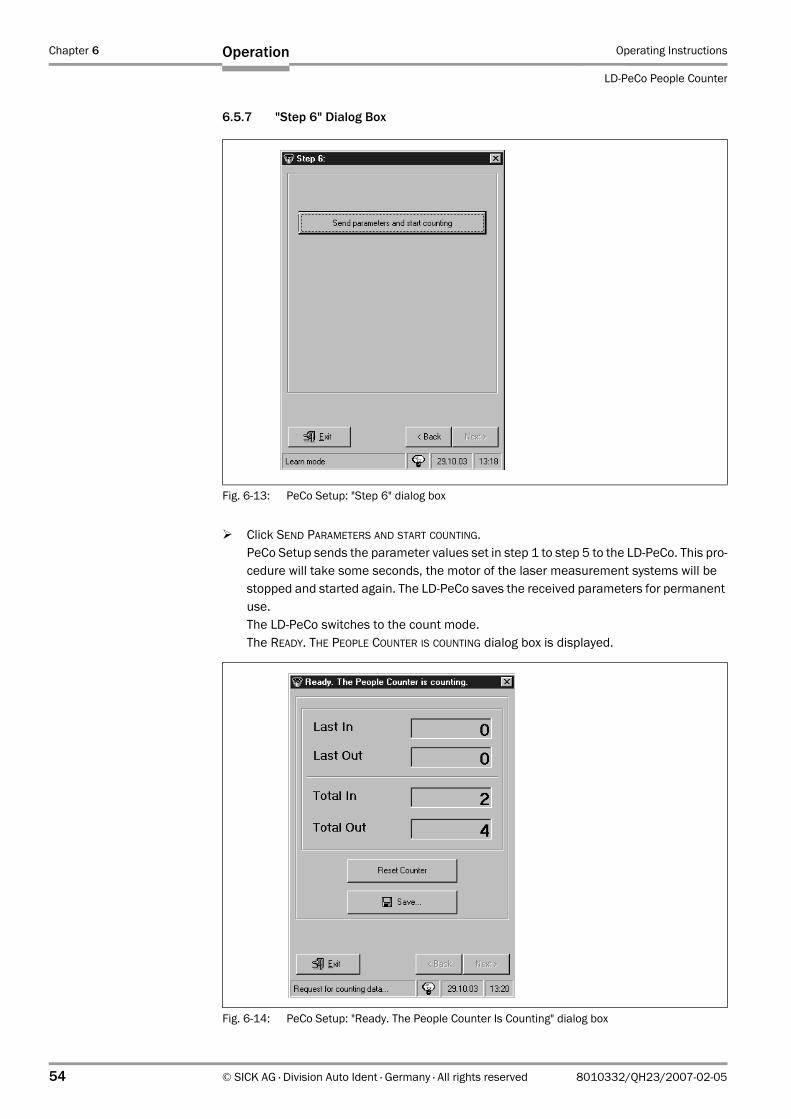
Chapter 6 Operating Instructions
LD-PeCo People Counter
54 © SICK AG · Division Auto Ident · Germany · All rights reserved 8010332/QH23/2007-02-05
Operation
6.5.7 "Step 6" Dialog Box
Click SEND PARAMETERS AND START COUNTING.PeCo Setup sends the parameter values set in step 1 to step 5 to the LD-PeCo. This pro-cedure will take some seconds, the motor of the laser measurement systems will be stopped and started again. The LD-PeCo saves the received parameters for permanent use.The LD-PeCo switches to the count mode. The READY. THE PEOPLE COUNTER IS COUNTING dialog box is displayed.
Fig. 6-13: PeCo Setup: "Step 6" dialog box
Fig. 6-14: PeCo Setup: "Ready. The People Counter Is Counting" dialog box
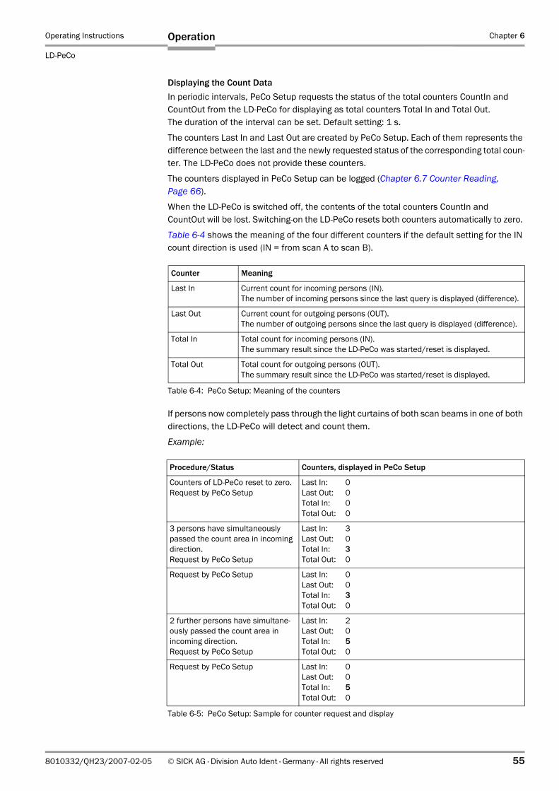
Operating Instructions Chapter 6
LD-PeCo
Operation
8010332/QH23/2007-02-05 © SICK AG · Division Auto Ident · Germany · All rights reserved 55
Displaying the Count DataIn periodic intervals, PeCo Setup requests the status of the total counters CountIn and CountOut from the LD-PeCo for displaying as total counters Total In and Total Out. The duration of the interval can be set. Default setting: 1 s.
The counters Last In and Last Out are created by PeCo Setup. Each of them represents the difference between the last and the newly requested status of the corresponding total coun-ter. The LD-PeCo does not provide these counters.
The counters displayed in PeCo Setup can be logged (Chapter 6.7 Counter Reading, Page 66).
When the LD-PeCo is switched off, the contents of the total counters CountIn and CountOut will be lost. Switching-on the LD-PeCo resets both counters automatically to zero.
Table 6-4 shows the meaning of the four different counters if the default setting for the IN count direction is used (IN = from scan A to scan B).
If persons now completely pass through the light curtains of both scan beams in one of both directions, the LD-PeCo will detect and count them.
Example:
Counter Meaning
Last In Current count for incoming persons (IN).The number of incoming persons since the last query is displayed (difference).
Last Out Current count for outgoing persons (OUT).The number of outgoing persons since the last query is displayed (difference).
Total In Total count for incoming persons (IN).The summary result since the LD-PeCo was started/reset is displayed.
Total Out Total count for outgoing persons (OUT).The summary result since the LD-PeCo was started/reset is displayed.
Table 6-4: PeCo Setup: Meaning of the counters
Procedure/Status Counters, displayed in PeCo Setup
Counters of LD-PeCo reset to zero.Request by PeCo Setup
Last In: 0Last Out: 0Total In: 0Total Out: 0
3 persons have simultaneously passed the count area in incoming direction.Request by PeCo Setup
Last In: 3Last Out: 0Total In: 3Total Out: 0
Request by PeCo Setup Last In: 0Last Out: 0Total In: 3Total Out: 0
2 further persons have simultane-ously passed the count area in incoming direction.Request by PeCo Setup
Last In: 2Last Out: 0Total In: 5Total Out: 0
Request by PeCo Setup Last In: 0Last Out: 0Total In: 5Total Out: 0
Table 6-5: PeCo Setup: Sample for counter request and display
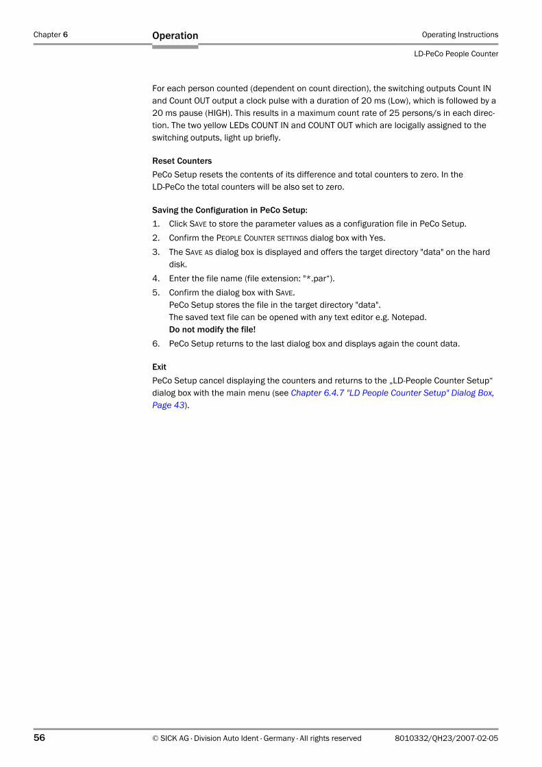
Chapter 6 Operating Instructions
LD-PeCo People Counter
56 © SICK AG · Division Auto Ident · Germany · All rights reserved 8010332/QH23/2007-02-05
Operation
For each person counted (dependent on count direction), the switching outputs Count IN and Count OUT output a clock pulse with a duration of 20 ms (Low), which is followed by a 20 ms pause (HIGH). This results in a maximum count rate of 25 persons/s in each direc-tion. The two yellow LEDs COUNT IN and COUNT OUT which are locigally assigned to the switching outputs, light up briefly.
Reset CountersPeCo Setup resets the contents of its difference and total counters to zero. In the LD-PeCo the total counters will be also set to zero.
Saving the Configuration in PeCo Setup:1. Click SAVE to store the parameter values as a configuration file in PeCo Setup.2. Confirm the PEOPLE COUNTER SETTINGS dialog box with Yes.3. The SAVE AS dialog box is displayed and offers the target directory "data" on the hard
disk.4. Enter the file name (file extension: "*.par“).5. Confirm the dialog box with SAVE.
PeCo Setup stores the file in the target directory "data".The saved text file can be opened with any text editor e.g. Notepad.Do not modify the file!
6. PeCo Setup returns to the last dialog box and displays again the count data.
ExitPeCo Setup cancel displaying the counters and returns to the „LD-People Counter Setup“ dialog box with the main menu (see Chapter 6.4.7 "LD People Counter Setup" Dialog Box, Page 43).
Operating Instructions Chapter 6
LD-PeCo
Operation
8010332/QH23/2007-02-05 © SICK AG · Division Auto Ident · Germany · All rights reserved 57
6.6 Maintenance
With the five tabs in the MAINTENANCE menu you can optimize the current parameter values for a LD-PeCo in operation (count mode), exception: learning the outline is only possible in configuration mode. This function is provided by PeCo Setup.When choosing the menu, PeCo Setup automatically requests the current parameter values from the LD-PeCo for displaying in the tabs.
Note Modified parameters are not sent to the LD-PeCo until you choose SEND PARAMETERS.
6.6.1 "Scanner" Tab
Changing the IN count direction:1. To change the count direction, click the appropriate check box.2. Click SET COUNT DIRECTION to send the modified parameter value to the LD-PeCo.
The LD-PeCo saves the received parameter for temporary use.3. To save the parameter permanently, choose the COMMANDS tab (Fig. 6-21, Page 63).
Click STOP COUNTING and then click START COUNTING.
Changing the IN count direction of default settingIf you change the IN count direction, the assignment of the switching outputs, the LEDs and the data fields in the data output for CountIN and CountOUT will be also changed.The incoming persons in CountIN will switched to incoming persons in CountOUT, the out-going persons in CountOUT will switched to outgoing persons in CountIN.Note this condition when wiring the switching outputs or when processing the count data externally via the data interface!
Fig. 6-15: PeCo Setup: "Scanner" tab
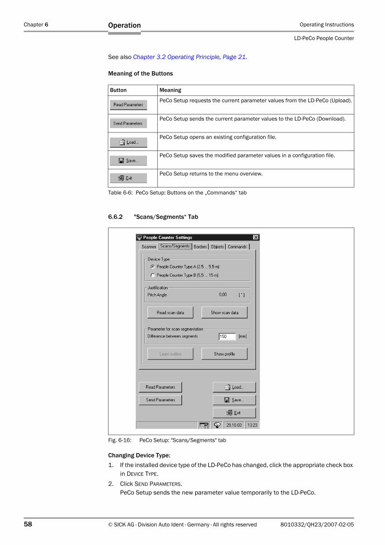
Chapter 6 Operating Instructions
LD-PeCo People Counter
58 © SICK AG · Division Auto Ident · Germany · All rights reserved 8010332/QH23/2007-02-05
Operation
See also Chapter 3.2 Operating Principle, Page 21.
Meaning of the Buttons
6.6.2 "Scans/Segments“ Tab
Changing Device Type:1. If the installed device type of the LD-PeCo has changed, click the appropriate check box
in DEVICE TYPE.2. Click SEND PARAMETERS.
PeCo Setup sends the new parameter value temporarily to the LD-PeCo.
Button Meaning
PeCo Setup requests the current parameter values from the LD-PeCo (Upload).
PeCo Setup sends the current parameter values to the LD-PeCo (Download).
PeCo Setup opens an existing configuration file.
PeCo Setup saves the modified parameter values in a configuration file.
PeCo Setup returns to the menu overview.
Table 6-6: PeCo Setup: Buttons on the „Commands“ tab
Fig. 6-16: PeCo Setup: "Scans/Segments" tab
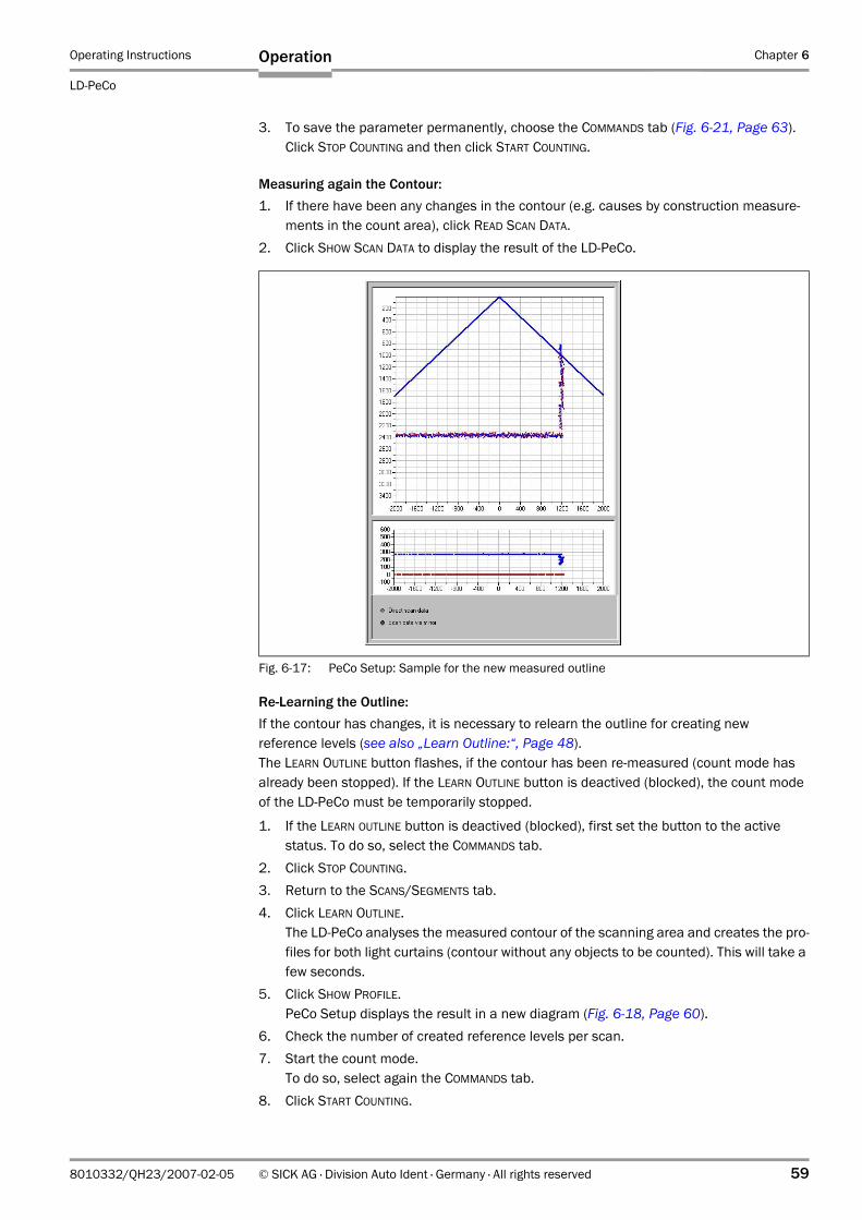
Operating Instructions Chapter 6
LD-PeCo
Operation
8010332/QH23/2007-02-05 © SICK AG · Division Auto Ident · Germany · All rights reserved 59
3. To save the parameter permanently, choose the COMMANDS tab (Fig. 6-21, Page 63).Click STOP COUNTING and then click START COUNTING.
Measuring again the Contour:1. If there have been any changes in the contour (e.g. causes by construction measure-
ments in the count area), click READ SCAN DATA.2. Click SHOW SCAN DATA to display the result of the LD-PeCo.
Re-Learning the Outline:If the contour has changes, it is necessary to relearn the outline for creating new reference levels (see also „Learn Outline:“, Page 48). The LEARN OUTLINE button flashes, if the contour has been re-measured (count mode has already been stopped). If the LEARN OUTLINE button is deactived (blocked), the count mode of the LD-PeCo must be temporarily stopped.
1. If the LEARN OUTLINE button is deactived (blocked), first set the button to the active status. To do so, select the COMMANDS tab.
2. Click STOP COUNTING.3. Return to the SCANS/SEGMENTS tab.4. Click LEARN OUTLINE.
The LD-PeCo analyses the measured contour of the scanning area and creates the pro-files for both light curtains (contour without any objects to be counted). This will take a few seconds.
5. Click SHOW PROFILE.PeCo Setup displays the result in a new diagram (Fig. 6-18, Page 60).
6. Check the number of created reference levels per scan.7. Start the count mode.
To do so, select again the COMMANDS tab.8. Click START COUNTING.
Fig. 6-17: PeCo Setup: Sample for the new measured outline
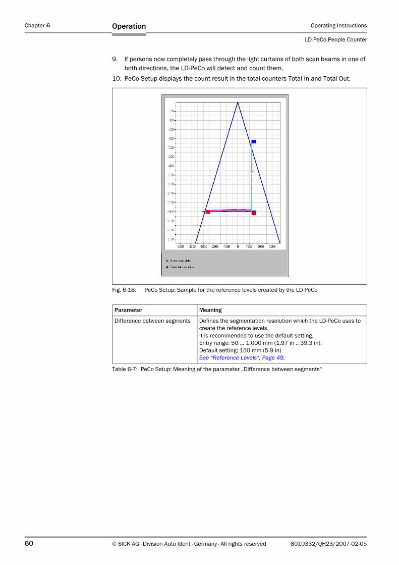
Chapter 6 Operating Instructions
LD-PeCo People Counter
60 © SICK AG · Division Auto Ident · Germany · All rights reserved 8010332/QH23/2007-02-05
Operation
9. If persons now completely pass through the light curtains of both scan beams in one of both directions, the LD-PeCo will detect and count them.
10. PeCo Setup displays the count result in the total counters Total In and Total Out.
Fig. 6-18: PeCo Setup: Sample for the reference levels created by the LD-PeCo
Parameter Meaning
Difference between segments Defines the segmentation resolution which the LD-PeCo uses to create the reference levels. It is recommended to use the default setting.Entry range: 50 ... 1,000 mm (1.97 in .. 39.3 in). Default setting: 150 mm (5.9 in)See “Reference Levels“, Page 49.
Table 6-7: PeCo Setup: Meaning of the parameter „Difference between segments“
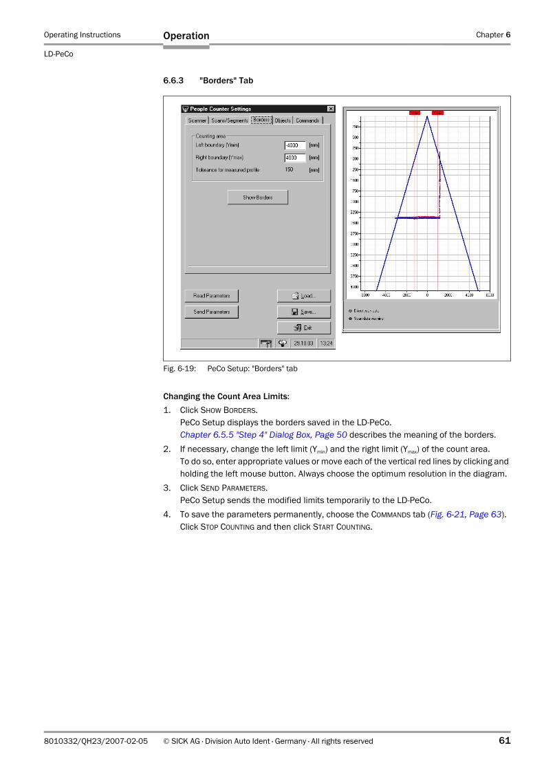
Operating Instructions Chapter 6
LD-PeCo
Operation
8010332/QH23/2007-02-05 © SICK AG · Division Auto Ident · Germany · All rights reserved 61
6.6.3 "Borders" Tab
Changing the Count Area Limits:1. Click SHOW BORDERS.
PeCo Setup displays the borders saved in the LD-PeCo.Chapter 6.5.5 "Step 4" Dialog Box, Page 50 describes the meaning of the borders.
2. If necessary, change the left limit (Ymin) and the right limit (Ymax) of the count area.To do so, enter appropriate values or move each of the vertical red lines by clicking and holding the left mouse button. Always choose the optimum resolution in the diagram.
3. Click SEND PARAMETERS.PeCo Setup sends the modified limits temporarily to the LD-PeCo.
4. To save the parameters permanently, choose the COMMANDS tab (Fig. 6-21, Page 63).Click STOP COUNTING and then click START COUNTING.
Fig. 6-19: PeCo Setup: "Borders" tab
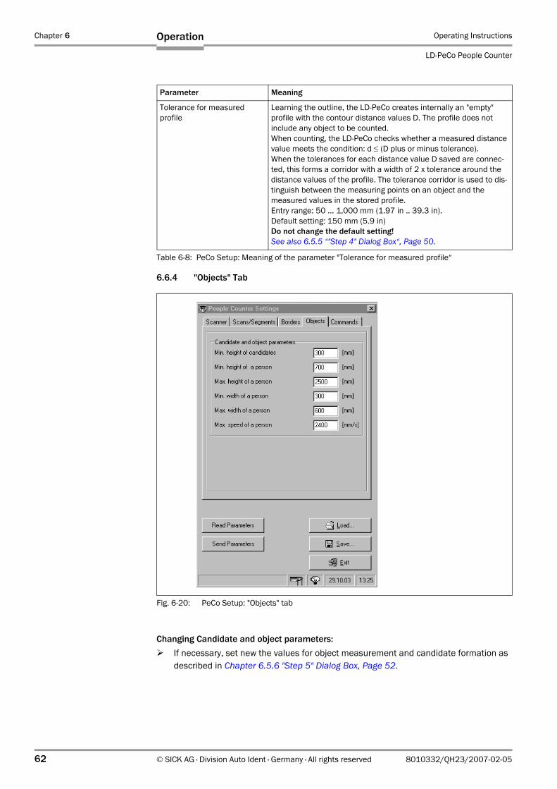
Chapter 6 Operating Instructions
LD-PeCo People Counter
62 © SICK AG · Division Auto Ident · Germany · All rights reserved 8010332/QH23/2007-02-05
Operation
6.6.4 "Objects" Tab
Changing Candidate and object parameters:If necessary, set new the values for object measurement and candidate formation as described in Chapter 6.5.6 "Step 5" Dialog Box, Page 52.
Parameter Meaning
Tolerance for measured profile
Learning the outline, the LD-PeCo creates internally an "empty" profile with the contour distance values D. The profile does not include any object to be counted. When counting, the LD-PeCo checks whether a measured distance value meets the condition: d ≤ (D plus or minus tolerance). When the tolerances for each distance value D saved are connec-ted, this forms a corridor with a width of 2 x tolerance around the distance values of the profile. The tolerance corridor is used to dis-tinguish between the measuring points on an object and the measured values in the stored profile. Entry range: 50 ... 1,000 mm (1.97 in .. 39.3 in). Default setting: 150 mm (5.9 in)Do not change the default setting!See also 6.5.5 “"Step 4" Dialog Box“, Page 50.
Table 6-8: PeCo Setup: Meaning of the parameter "Tolerance for measured profile“
Fig. 6-20: PeCo Setup: "Objects" tab
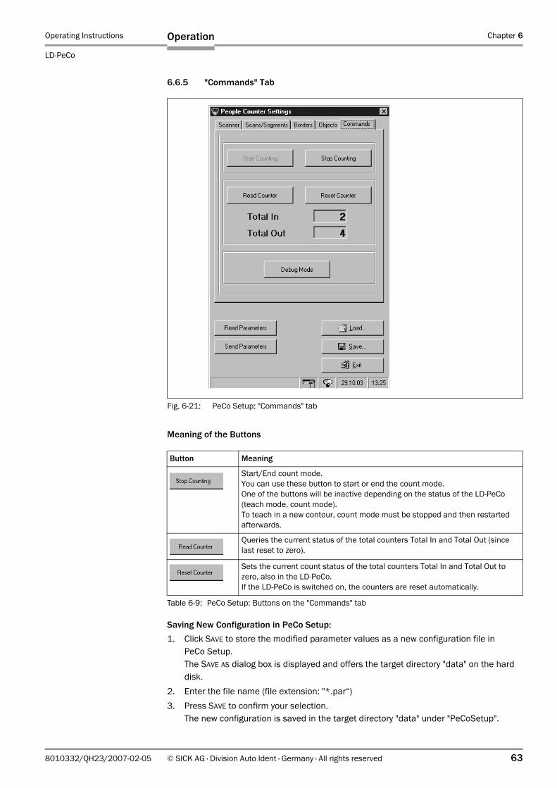
Operating Instructions Chapter 6
LD-PeCo
Operation
8010332/QH23/2007-02-05 © SICK AG · Division Auto Ident · Germany · All rights reserved 63
6.6.5 "Commands" Tab
Meaning of the Buttons
Saving New Configuration in PeCo Setup:1. Click SAVE to store the modified parameter values as a new configuration file in
PeCo Setup.The SAVE AS dialog box is displayed and offers the target directory "data" on the hard disk.
2. Enter the file name (file extension: "*.par“)3. Press SAVE to confirm your selection.
The new configuration is saved in the target directory "data" under "PeCoSetup".
Fig. 6-21: PeCo Setup: "Commands" tab
Button Meaning
Start/End count mode.You can use these button to start or end the count mode.One of the buttons will be inactive depending on the status of the LD-PeCo (teach mode, count mode). To teach in a new contour, count mode must be stopped and then restarted afterwards.
Queries the current status of the total counters Total In and Total Out (since last reset to zero).
Sets the current count status of the total counters Total In and Total Out to zero, also in the LD-PeCo.If the LD-PeCo is switched on, the counters are reset automatically.
Table 6-9: PeCo Setup: Buttons on the "Commands" tab
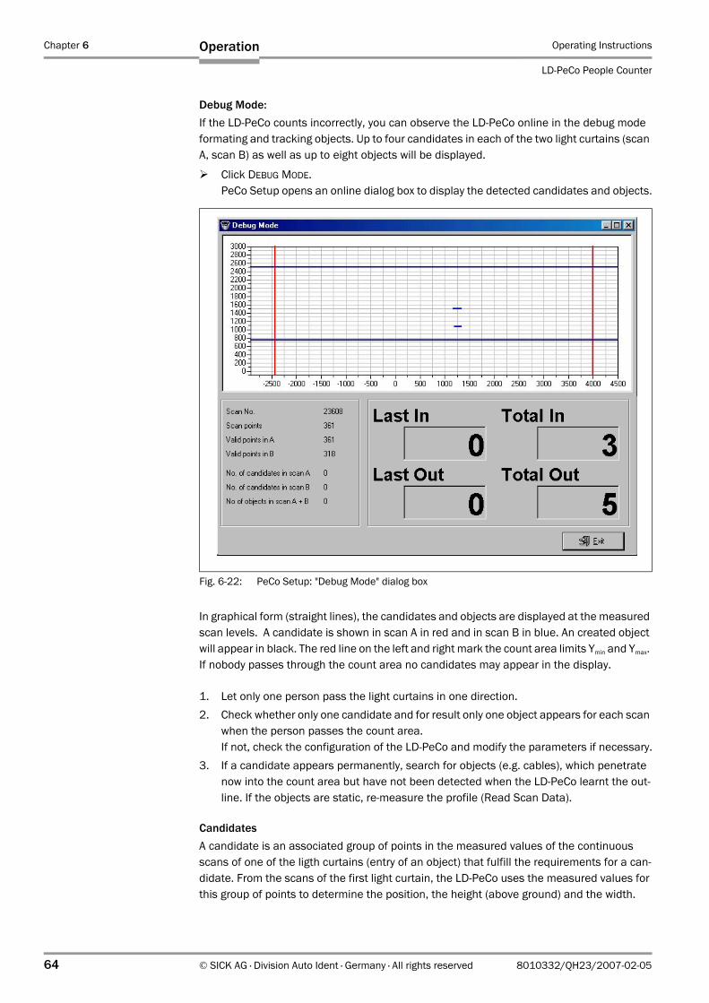
Chapter 6 Operating Instructions
LD-PeCo People Counter
64 © SICK AG · Division Auto Ident · Germany · All rights reserved 8010332/QH23/2007-02-05
Operation
Debug Mode:If the LD-PeCo counts incorrectly, you can observe the LD-PeCo online in the debug mode formating and tracking objects. Up to four candidates in each of the two light curtains (scan A, scan B) as well as up to eight objects will be displayed.
Click DEBUG MODE.PeCo Setup opens an online dialog box to display the detected candidates and objects.
In graphical form (straight lines), the candidates and objects are displayed at the measured scan levels. A candidate is shown in scan A in red and in scan B in blue. An created object will appear in black. The red line on the left and right mark the count area limits Ymin and Ymax. If nobody passes through the count area no candidates may appear in the display.
1. Let only one person pass the light curtains in one direction.2. Check whether only one candidate and for result only one object appears for each scan
when the person passes the count area.If not, check the configuration of the LD-PeCo and modify the parameters if necessary.
3. If a candidate appears permanently, search for objects (e.g. cables), which penetrate now into the count area but have not been detected when the LD-PeCo learnt the out-line. If the objects are static, re-measure the profile (Read Scan Data).
CandidatesA candidate is an associated group of points in the measured values of the continuous scans of one of the ligth curtains (entry of an object) that fulfill the requirements for a can-didate. From the scans of the first light curtain, the LD-PeCo uses the measured values for this group of points to determine the position, the height (above ground) and the width.
Fig. 6-22: PeCo Setup: "Debug Mode" dialog box
Operating Instructions Chapter 6
LD-PeCo
Operation
8010332/QH23/2007-02-05 © SICK AG · Division Auto Ident · Germany · All rights reserved 65
If this data fulfills the criteria for minimum height of candidates, the LD-PeCo creates a can-didate from this group of points.
ObjectsThe LD-PeCo creates objects from these candidates. In this way, a zone is formed for each candidate. If an object is already in this zone, the LD-PeCo assigns the candidate to this ob-ject. If not, a new object for the candidate is generated. If further candidates are located in the object zone, these are also assigned to the object. This means that several candidates can (and must) merge to form a single object.
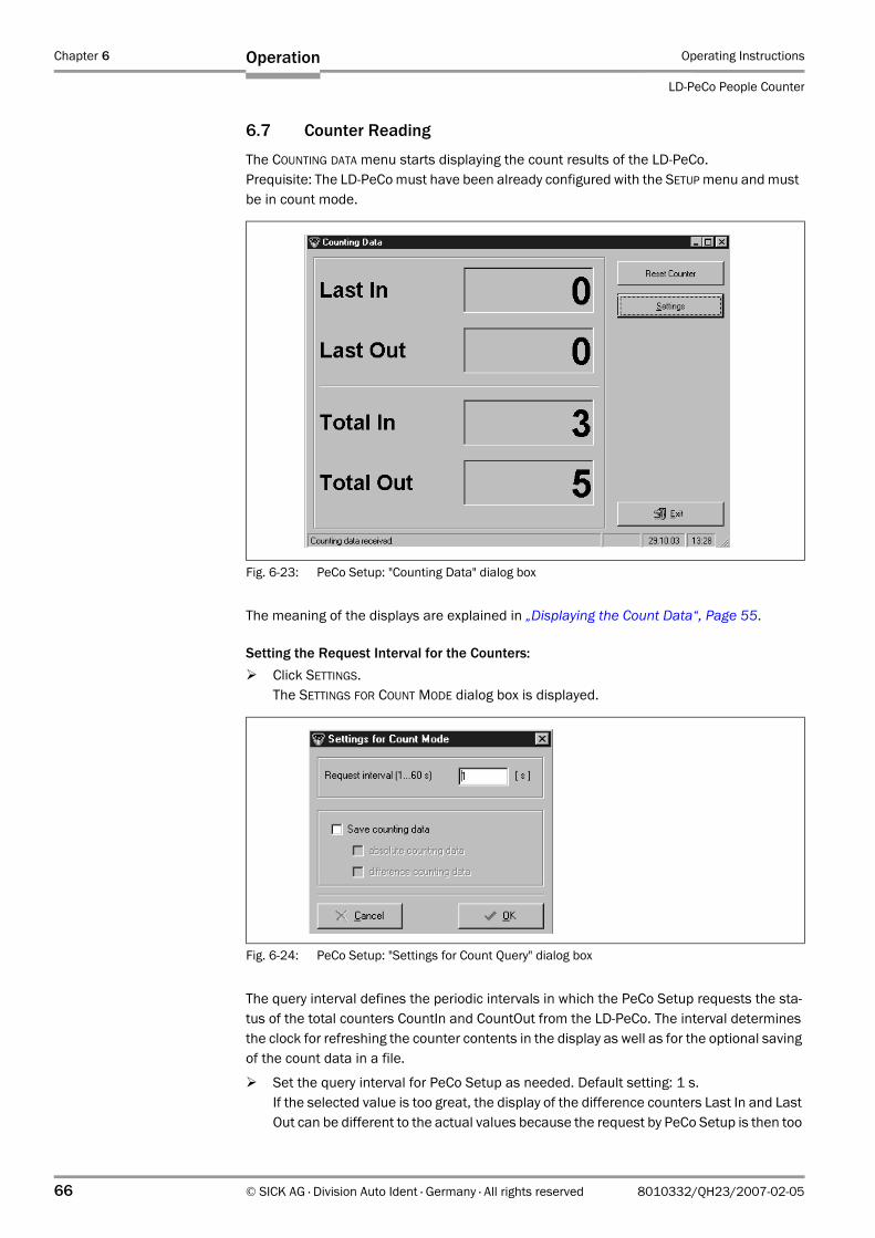
Chapter 6 Operating Instructions
LD-PeCo People Counter
66 © SICK AG · Division Auto Ident · Germany · All rights reserved 8010332/QH23/2007-02-05
Operation
6.7 Counter Reading
The COUNTING DATA menu starts displaying the count results of the LD-PeCo.Prequisite: The LD-PeCo must have been already configured with the SETUP menu and must be in count mode.
The meaning of the displays are explained in „Displaying the Count Data“, Page 55.
Setting the Request Interval for the Counters:Click SETTINGS.The SETTINGS FOR COUNT MODE dialog box is displayed.
The query interval defines the periodic intervals in which the PeCo Setup requests the sta-tus of the total counters CountIn and CountOut from the LD-PeCo. The interval determines the clock for refreshing the counter contents in the display as well as for the optional saving of the count data in a file.
Set the query interval for PeCo Setup as needed. Default setting: 1 s.If the selected value is too great, the display of the difference counters Last In and Last Out can be different to the actual values because the request by PeCo Setup is then too
Fig. 6-23: PeCo Setup: "Counting Data" dialog box
Fig. 6-24: PeCo Setup: "Settings for Count Query" dialog box
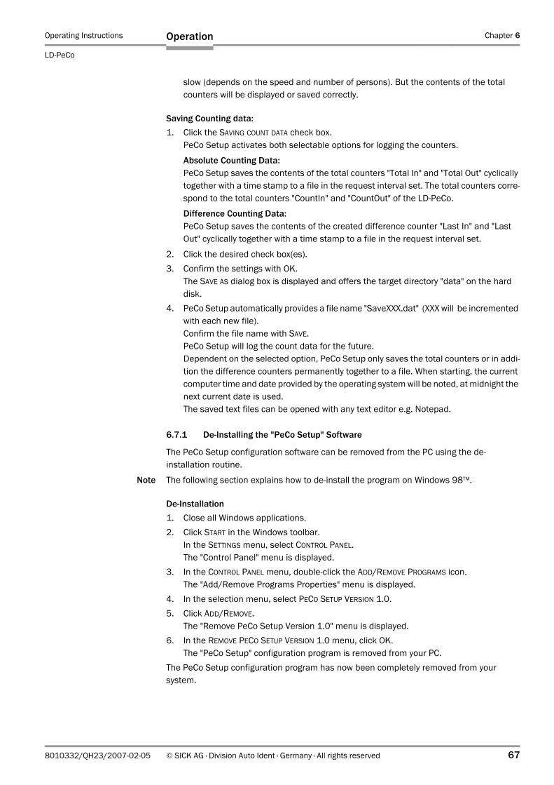
Operating Instructions Chapter 6
LD-PeCo
Operation
8010332/QH23/2007-02-05 © SICK AG · Division Auto Ident · Germany · All rights reserved 67
slow (depends on the speed and number of persons). But the contents of the total counters will be displayed or saved correctly.
Saving Counting data:1. Click the SAVING COUNT DATA check box.
PeCo Setup activates both selectable options for logging the counters.
Absolute Counting Data:PeCo Setup saves the contents of the total counters "Total In" and "Total Out" cyclically together with a time stamp to a file in the request interval set. The total counters corre-spond to the total counters "CountIn" and "CountOut" of the LD-PeCo.
Difference Counting Data:PeCo Setup saves the contents of the created difference counter "Last In" and "Last Out" cyclically together with a time stamp to a file in the request interval set.
2. Click the desired check box(es). 3. Confirm the settings with OK.
The SAVE AS dialog box is displayed and offers the target directory "data" on the hard disk.
4. PeCo Setup automatically provides a file name "SaveXXX.dat" (XXX will be incremented with each new file).Confirm the file name with SAVE.PeCo Setup will log the count data for the future.Dependent on the selected option, PeCo Setup only saves the total counters or in addi-tion the difference counters permanently together to a file. When starting, the current computer time and date provided by the operating system will be noted, at midnight the next current date is used.The saved text files can be opened with any text editor e.g. Notepad.
6.7.1 De-Installing the "PeCo Setup" Software
The PeCo Setup configuration software can be removed from the PC using the de-installation routine.
Note The following section explains how to de-install the program on Windows 98TM.
De-Installation1. Close all Windows applications.2. Click START in the Windows toolbar.
In the SETTINGS menu, select CONTROL PANEL.The "Control Panel" menu is displayed.
3. In the CONTROL PANEL menu, double-click the ADD/REMOVE PROGRAMS icon.The "Add/Remove Programs Properties" menu is displayed.
4. In the selection menu, select PECO SETUP VERSION 1.0.5. Click ADD/REMOVE.
The "Remove PeCo Setup Version 1.0" menu is displayed.6. In the REMOVE PECO SETUP VERSION 1.0 menu, click OK.
The "PeCo Setup" configuration program is removed from your PC.The PeCo Setup configuration program has now been completely removed from your system.
Chapter 6 Operating Instructions
LD-PeCo People Counter
68 © SICK AG · Division Auto Ident · Germany · All rights reserved 8010332/QH23/2007-02-05
Operation
6.8 Switching Off the LD-PeCo
Switch off the power supply for the LD-PeCo.The last parameter set stored permanently in the LD-PeCo remains valid.If switched on again, the LD-PeCo will automatically start in count mode.
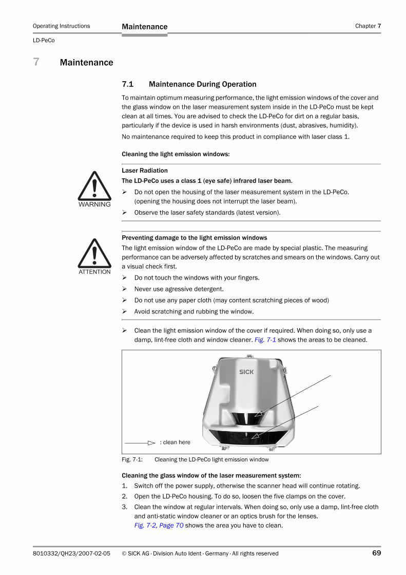
Operating Instructions Chapter 7
LD-PeCo
Maintenance
8010332/QH23/2007-02-05 © SICK AG · Division Auto Ident · Germany · All rights reserved 69
7 Maintenance
7.1 Maintenance During Operation
To maintain optimum measuring performance, the light emission windows of the cover and the glass window on the laser measurement system inside in the LD-PeCo must be kept clean at all times. You are advised to check the LD-PeCo for dirt on a regular basis, particularly if the device is used in harsh environments (dust, abrasives, humidity).
No maintenance required to keep this product in compliance with laser class 1.
Cleaning the light emission windows:
Laser RadiationThe LD-PeCo uses a class 1 (eye safe) infrared laser beam.
Do not open the housing of the laser measurement system in the LD-PeCo.(opening the housing does not interrupt the laser beam).
Observe the laser safety standards (latest version).
Preventing damage to the light emission windowsThe light emission window of the LD-PeCo are made by special plastic. The measuring performance can be adversely affected by scratches and smears on the windows. Carry out a visual check first.
Do not touch the windows with your fingers.
Never use agressive detergent.
Do not use any paper cloth (may content scratching pieces of wood)
Avoid scratching and rubbing the window.
Clean the light emission window of the cover if required. When doing so, only use a damp, lint-free cloth and window cleaner. Fig. 7-1 shows the areas to be cleaned.
Cleaning the glass window of the laser measurement system:1. Switch off the power supply, otherwise the scanner head will continue rotating.2. Open the LD-PeCo housing. To do so, loosen the five clamps on the cover.3. Clean the window at regular intervals. When doing so, only use a damp, lint-free cloth
and anti-static window cleaner or an optics brush for the lenses. Fig. 7-2, Page 70 shows the area you have to clean.
Fig. 7-1: Cleaning the LD-PeCo light emission window
: clean here
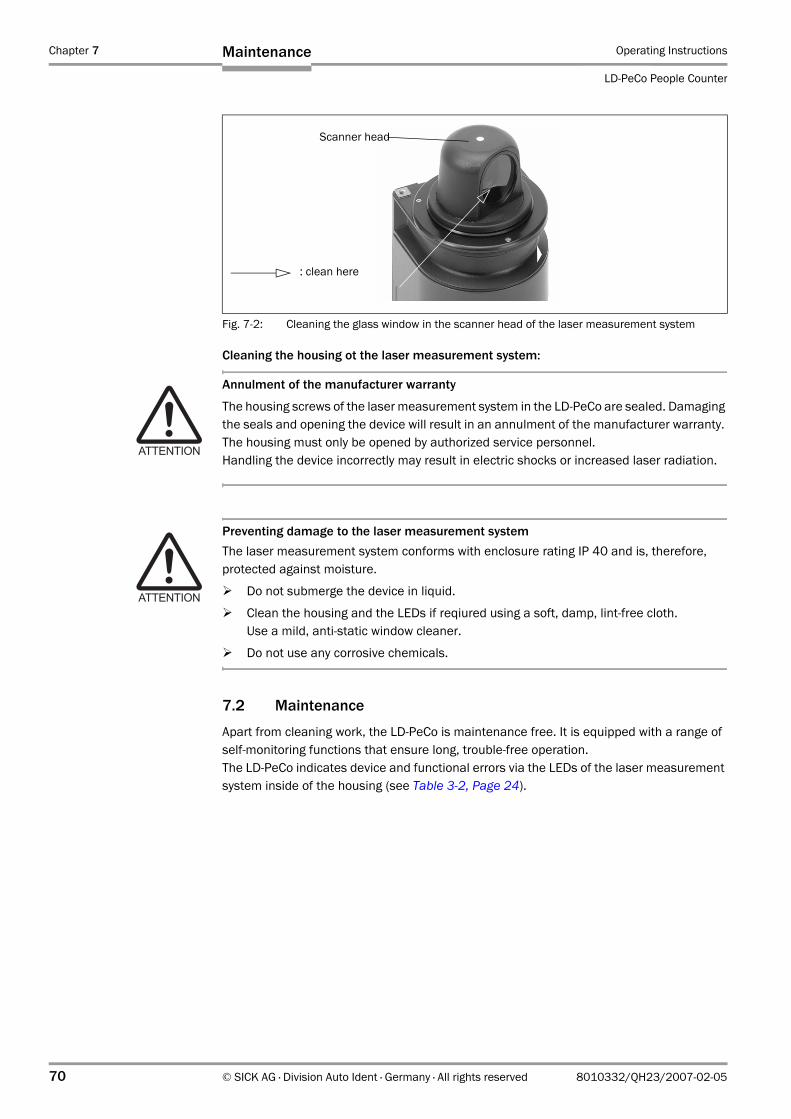
Chapter 7 Operating Instructions
LD-PeCo People Counter
70 © SICK AG · Division Auto Ident · Germany · All rights reserved 8010332/QH23/2007-02-05
Maintenance
Cleaning the housing ot the laser measurement system:
Annulment of the manufacturer warranty
The housing screws of the laser measurement system in the LD-PeCo are sealed. Damaging the seals and opening the device will result in an annulment of the manufacturer warranty. The housing must only be opened by authorized service personnel.Handling the device incorrectly may result in electric shocks or increased laser radiation.
Preventing damage to the laser measurement systemThe laser measurement system conforms with enclosure rating IP 40 and is, therefore, protected against moisture.
Do not submerge the device in liquid.
Clean the housing and the LEDs if reqiured using a soft, damp, lint-free cloth. Use a mild, anti-static window cleaner.
Do not use any corrosive chemicals.
7.2 Maintenance
Apart from cleaning work, the LD-PeCo is maintenance free. It is equipped with a range of self-monitoring functions that ensure long, trouble-free operation. The LD-PeCo indicates device and functional errors via the LEDs of the laser measurement system inside of the housing (see Table 3-2, Page 24).
Fig. 7-2: Cleaning the glass window in the scanner head of the laser measurement system
Scanner head
: clean here
Operating Instructions Chapter 7
LD-PeCo
Maintenance
8010332/QH23/2007-02-05 © SICK AG · Division Auto Ident · Germany · All rights reserved 71
7.3 Disposal
When you have removed the device from service, dispose of unusable or irreplaceable devices in an environmentally-sound manner:
1. Observe the valid, country-specific waste disposal regulations.2. Open the clamps on the cover and remove the cover.3. Remove the D sub plug at the interface adapter. 4. Disassemble the metal insert with the laser measurement system and the mirrors (pan-
head screws). 5. Disassemble the laser measurement system from the insert.6. Disassemble the housing of the laser measurement system.7. Disassemble the electronics modules.8. Remove the glass screen and glass components and dispose of them in a waste glass
recycling system.9. Send the die-cast aluminum frame and cover of the laser measurement system for
recycling.10. Dispose of the electronics modules and the cover as special waste.
SICK AG currently does not accept unusable or irreparable devices.
Chapter 7 Operating Instructions
LD-PeCo People Counter
72 © SICK AG · Division Auto Ident · Germany · All rights reserved 8010332/QH23/2007-02-05
Maintenance
Notes:
Operating Instructions Chapter 8
LD-PeCo
Troubleshooting
8010332/QH23/2007-02-05 © SICK AG · Division Auto Ident · Germany · All rights reserved 73
8 Troubleshooting
8.1 Overview of Possible Errors and Malfunctions
8.1.1 Mounting Errors
• LD-PeCo is incorrectly mounted (e.g. in vicinity of doors) • LD-PeCo is incorrectly aligned (rotation angles)• More than one LD-PeCo used: the systems are arranged incorrectly.
8.1.2 Electrical Installation Errors
• The LD-PeCo interfaces are incorrectly connected.
8.1.3 Parameterization Errors
• The technical limitations of the device have not been taken into account.• Parameter values have not been adapted to the situation on-site.
8.1.4 Operational Malfunctions
• Device errors (hardware/software)
8.2 Monitoring Error and Fault Signs
The LD-PeCo monitors itself during operation:
• After the power supply has been switched on, the LD-PeCo automatically carries out a self-test during which it checks important hardware components before it is initialized (parameter set loaded and device functions initialized).
• During operation, the LD-PeCo continuously monitors the scanner head to ensure that it is rotating properly.
• The red LED "ERROR" of the laser measurement system lights up in the housing if an error occurs.
8.3 Troubleshooting
To carry out troubleshooting, you require the following tools:
• Tool• A digital measuring device (ammeter/voltmeter)• A PC running PeCo Setup software• A setup cable 1
(defined for RS 422/RS 232 interface converter B&B Model 4WSDR9) • An RS 422/RS 232 interface converter• An RS 232 data cable (1:1 pin assignment)
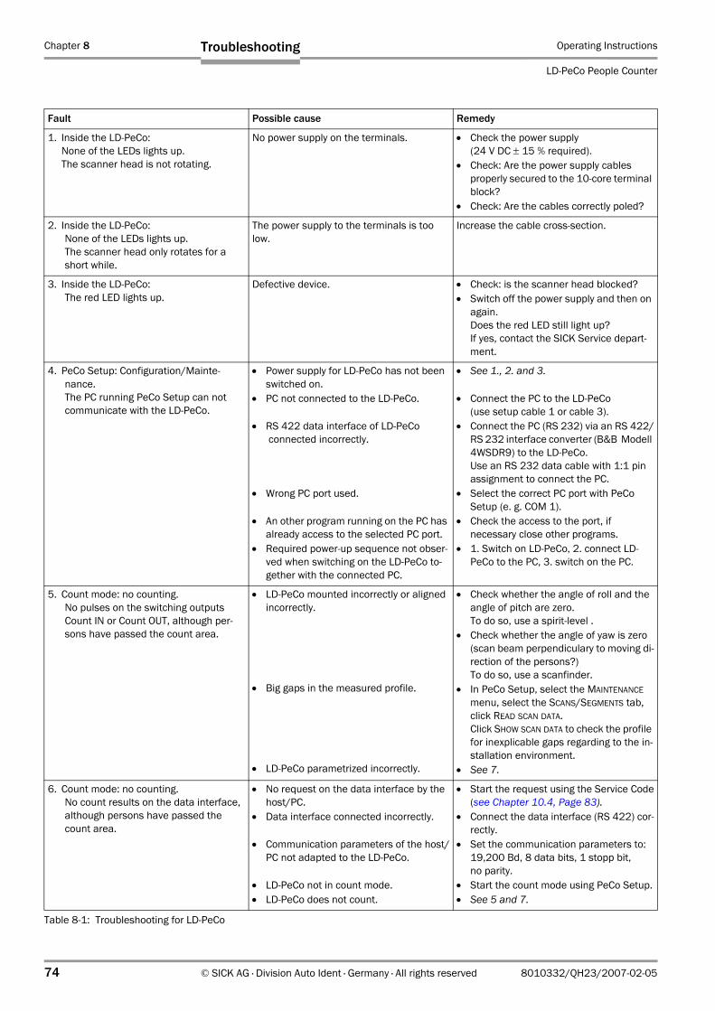
Chapter 8 Operating Instructions
LD-PeCo People Counter
74 © SICK AG · Division Auto Ident · Germany · All rights reserved 8010332/QH23/2007-02-05
Troubleshooting
Fault Possible cause Remedy
1. Inside the LD-PeCo: None of the LEDs lights up.The scanner head is not rotating.
No power supply on the terminals. • Check the power supply(24 V DC ± 15 % required).
• Check: Are the power supply cablesproperly secured to the 10-core terminal block?
• Check: Are the cables correctly poled?
2. Inside the LD-PeCo: None of the LEDs lights up.The scanner head only rotates for a short while.
The power supply to the terminals is too low.
Increase the cable cross-section.
3. Inside the LD-PeCo: The red LED lights up.
Defective device. • Check: is the scanner head blocked?• Switch off the power supply and then on
again.Does the red LED still light up? If yes, contact the SICK Service depart-ment.
4. PeCo Setup: Configuration/Mainte-nance.The PC running PeCo Setup can not communicate with the LD-PeCo.
• Power supply for LD-PeCo has not been switched on.
• PC not connected to the LD-PeCo.
• RS 422 data interface of LD-PeCo connected incorrectly.
• Wrong PC port used.
• An other program running on the PC has already access to the selected PC port.
• Required power-up sequence not obser-ved when switching on the LD-PeCo to-gether with the connected PC.
• See 1., 2. and 3.
• Connect the PC to the LD-PeCo (use setup cable 1 or cable 3).
• Connect the PC (RS 232) via an RS 422/RS 232 interface converter (B&B Modell 4WSDR9) to the LD-PeCo.Use an RS 232 data cable with 1:1 pin assignment to connect the PC.
• Select the correct PC port with PeCo Setup (e. g. COM 1).
• Check the access to the port, if necessary close other programs.
• 1. Switch on LD-PeCo, 2. connect LD-PeCo to the PC, 3. switch on the PC.
5. Count mode: no counting.No pulses on the switching outputs Count IN or Count OUT, although per-sons have passed the count area.
• LD-PeCo mounted incorrectly or aligned incorrectly.
• Big gaps in the measured profile.
• LD-PeCo parametrized incorrectly.
• Check whether the angle of roll and the angle of pitch are zero. To do so, use a spirit-level .
• Check whether the angle of yaw is zero (scan beam perpendiculary to moving di-rection of the persons?) To do so, use a scanfinder.
• In PeCo Setup, select the MAINTENANCE menu, select the SCANS/SEGMENTS tab, click READ SCAN DATA. Click SHOW SCAN DATA to check the profile for inexplicable gaps regarding to the in-stallation environment.
• See 7.
6. Count mode: no counting.No count results on the data interface, although persons have passed the count area.
• No request on the data interface by the host/PC.
• Data interface connected incorrectly.
• Communication parameters of the host/PC not adapted to the LD-PeCo.
• LD-PeCo not in count mode.• LD-PeCo does not count.
• Start the request using the Service Code(see Chapter 10.4, Page 83).
• Connect the data interface (RS 422) cor-rectly.
• Set the communication parameters to: 19,200 Bd, 8 data bits, 1 stopp bit, no parity.
• Start the count mode using PeCo Setup.• See 5 and 7.
Table 8-1: Troubleshooting for LD-PeCo
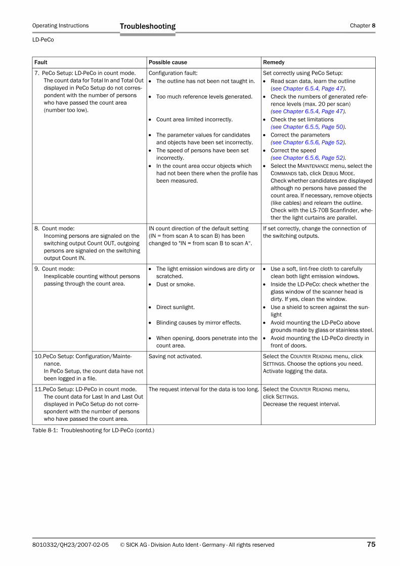
Operating Instructions Chapter 8
LD-PeCo
Troubleshooting
8010332/QH23/2007-02-05 © SICK AG · Division Auto Ident · Germany · All rights reserved 75
7. PeCo Setup: LD-PeCo in count mode.The count data for Total In and Total Out displayed in PeCo Setup do not corres-pondent with the number of persons who have passed the count area (number too low).
Configuration fault:• The outline has not been not taught in.
• Too much reference levels generated.
• Count area limited incorrectly.
• The parameter values for candidates and objects have been set incorrectly.
• The speed of persons have been set incorrectly.
• In the count area occur objects which had not been there when the profile has been measured.
Set correctly using PeCo Setup: • Read scan data, learn the outline
(see Chapter 6.5.4, Page 47).• Check the numbers of generated refe-
rence levels (max. 20 per scan)(see Chapter 6.5.4, Page 47).
• Check the set limitations(see Chapter 6.5.5, Page 50).
• Correct the parameters(see Chapter 6.5.6, Page 52).
• Correct the speed(see Chapter 6.5.6, Page 52).
• Select the MAINTENANCE menu, select the COMMANDS tab, click DEBUG MODE.Check whether candidates are displayed although no persons have passed the count area. If necessary, remove objects (like cables) and relearn the outline.Check with the LS-70B Scanfinder, whe-ther the light curtains are parallel.
8. Count mode:Incoming persons are signaled on the switching output Count OUT, outgoing persons are signaled on the switching output Count IN.
IN count direction of the default setting (IN = from scan A to scan B) has been changed to "IN = from scan B to scan A“.
If set correctly, change the connection of the switching outputs.
9. Count mode:Inexplicable counting without persons passing through the count area.
• The light emission windows are dirty or scratched.
• Dust or smoke.
• Direct sunlight.
• Blinding causes by mirror effects.
• When opening, doors penetrate into the count area.
• Use a soft, lint-free cloth to carefully clean both light emission windows.
• Inside the LD-PeCo: check whether the glass window of the scanner head is dirty. If yes, clean the window.
• Use a shield to screen against the sun-light
• Avoid mounting the LD-PeCo above grounds made by glass or stainless steel.
• Avoid mounting the LD-PeCo directly in front of doors.
10.PeCo Setup: Configuration/Mainte-nance.In PeCo Setup, the count data have not been logged in a file.
Saving not activated. Select the COUNTER READING menu, click SETTINGS. Choose the options you need.Activate logging the data.
11.PeCo Setup: LD-PeCo in count mode.The count data for Last In and Last Out displayed in PeCo Setup do not corre-spondent with the number of persons who have passed the count area.
The request interval for the data is too long. Select the COUNTER READING menu, click SETTINGS.Decrease the request interval.
Fault Possible cause Remedy
Table 8-1: Troubleshooting for LD-PeCo (contd.)
Chapter 8 Operating Instructions
LD-PeCo People Counter
76 © SICK AG · Division Auto Ident · Germany · All rights reserved 8010332/QH23/2007-02-05
Troubleshooting
8.4 SICK Support
If a problem occurs repeatedly and cannot be rectified using the procedures provided, the LD-PeCo may be defective. The LD-PeCo does not contain any system components that can be repaired by the user.
Annulment of the manufacturer warranty
The housing screws of the laser measurement system in the LD-PeCo are sealed. Damaging the seals and opening the device will result in an annulment of the manufacturer warranty. The housing must only be opened by authorized service personnel.Handling the device incorrectly can result in a risk of injury due to electric shocks or increased laser radiation.
Please contact you local SICK office or subsidary:
• The telephone numbers and email addresses are listed on the back page of this manual.For postal addresses see also www.sick.com.
Please contact the SICK Service department before submitting the device for repair.
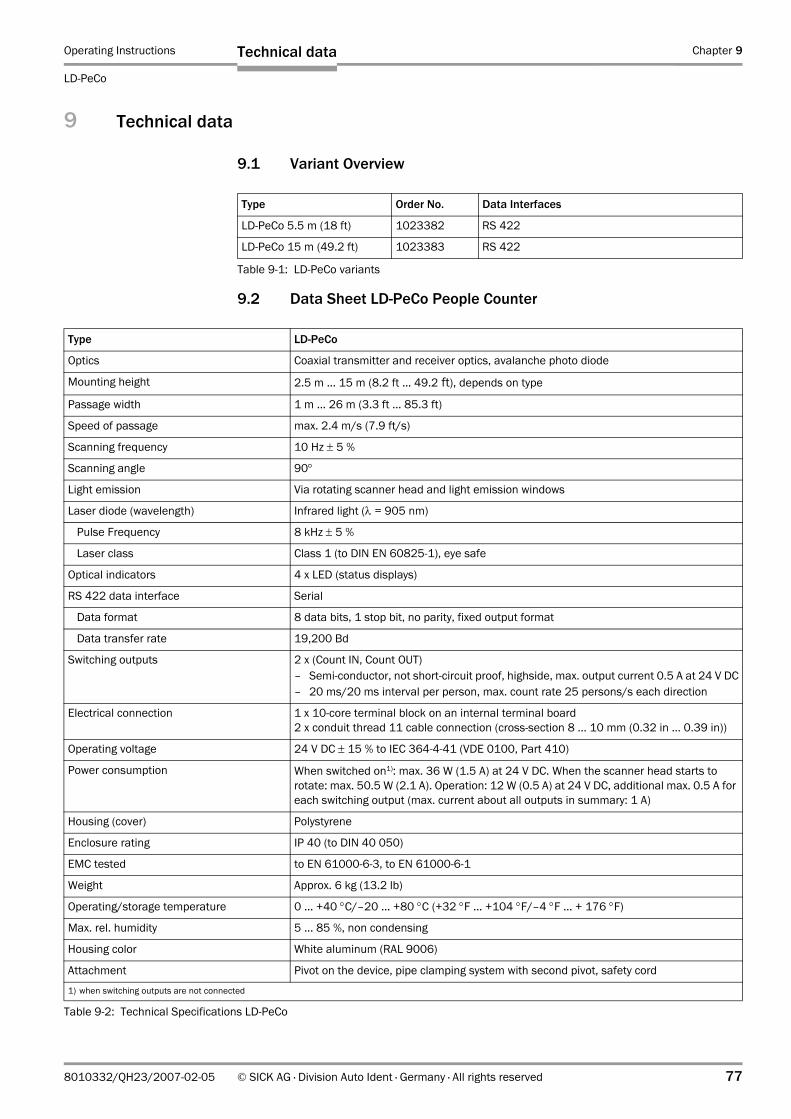
Operating Instructions Chapter 9
LD-PeCo
Technical data
8010332/QH23/2007-02-05 © SICK AG · Division Auto Ident · Germany · All rights reserved 77
9 Technical data
9.1 Variant Overview
9.2 Data Sheet LD-PeCo People Counter
Type Order No. Data Interfaces
LD-PeCo 5.5 m (18 ft) 1023382 RS 422
LD-PeCo 15 m (49.2 ft) 1023383 RS 422
Table 9-1: LD-PeCo variants
Type LD-PeCo
Optics Coaxial transmitter and receiver optics, avalanche photo diode
Mounting height 2.5 m ... 15 m (8.2 ft ... 49.2 ft), depends on type
Passage width 1 m ... 26 m (3.3 ft ... 85.3 ft)
Speed of passage max. 2.4 m/s (7.9 ft/s)
Scanning frequency 10 Hz ± 5 %
Scanning angle 90°
Light emission Via rotating scanner head and light emission windows
Laser diode (wavelength) Infrared light (λ = 905 nm)
Pulse Frequency 8 kHz ± 5 %
Laser class Class 1 (to DIN EN 60825-1), eye safe
Optical indicators 4 x LED (status displays)
RS 422 data interface Serial
Data format 8 data bits, 1 stop bit, no parity, fixed output format
Data transfer rate 19,200 Bd
Switching outputs 2 x (Count IN, Count OUT)– Semi-conductor, not short-circuit proof, highside, max. output current 0.5 A at 24 V DC– 20 ms/20 ms interval per person, max. count rate 25 persons/s each direction
Electrical connection 1 x 10-core terminal block on an internal terminal board2 x conduit thread 11 cable connection (cross-section 8 ... 10 mm (0.32 in ... 0.39 in))
Operating voltage 24 V DC ± 15 % to IEC 364-4-41 (VDE 0100, Part 410)
Power consumption When switched on1): max. 36 W (1.5 A) at 24 V DC. When the scanner head starts to rotate: max. 50.5 W (2.1 A). Operation: 12 W (0.5 A) at 24 V DC, additional max. 0.5 A for each switching output (max. current about all outputs in summary: 1 A)
Housing (cover) Polystyrene
Enclosure rating IP 40 (to DIN 40 050)
EMC tested to EN 61000-6-3, to EN 61000-6-1
Weight Approx. 6 kg (13.2 lb)
Operating/storage temperature 0 ... +40 °C/–20 ... +80 °C (+32 °F ... +104 °F/–4 °F ... + 176 °F)
Max. rel. humidity 5 ... 85 %, non condensing
Housing color White aluminum (RAL 9006)
Attachment Pivot on the device, pipe clamping system with second pivot, safety cord
1) when switching outputs are not connected
Table 9-2: Technical Specifications LD-PeCo
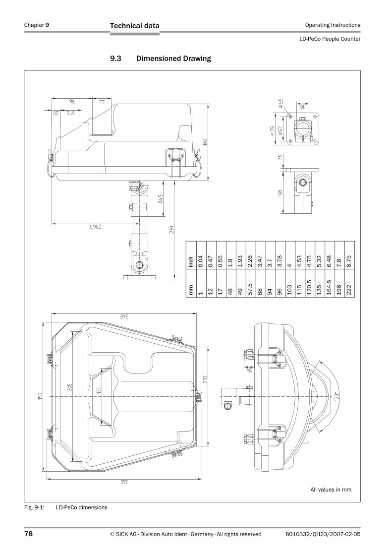
Chapter 9 Operating Instructions
LD-PeCo People Counter
78 © SICK AG · Division Auto Ident · Germany · All rights reserved 8010332/QH23/2007-02-05
Technical data
9.3 Dimensioned Drawing
Fig. 9-1: LD-PeCo dimensions
mm
inch
10.
04
120.
47
170.
55
481.
9
491.
93
57.5
2.26
883.
47
943.
7
963.
78
103
4
115
4.53
120.
54.
75
135
5.32
164.
56.
48
198
7.8
222
8.75
All values in mm
Operating Instructions Chapter 10
LD-PeCo
Appendix
8010332/QH23/2007-02-05 © SICK AG · Division Auto Ident · Germany · All rights reserved 79
10 Appendix
10.1 Overview of Appendix
The appendix contains the following additional information:
• Accessories• Dimensioned drawings of the accessories/connection block diagrams• Data communication via the data interface• Help in case of problems while starting the LD-PeCo• Replacing a LD-PeCo (copy parameter set)• Copy of EC Declaration of conformity (page 1)
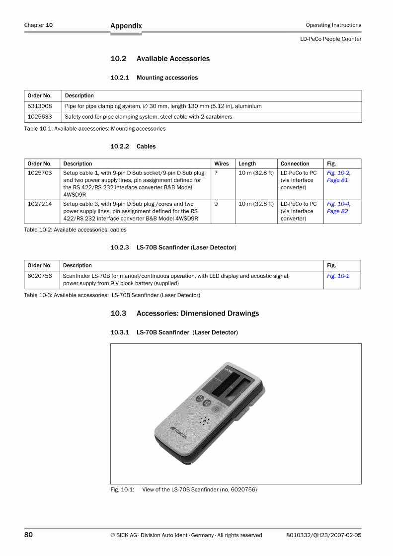
Chapter 10 Operating Instructions
LD-PeCo People Counter
80 © SICK AG · Division Auto Ident · Germany · All rights reserved 8010332/QH23/2007-02-05
Appendix
10.2 Available Accessories
10.2.1 Mounting accessories
10.2.2 Cables
10.2.3 LS-70B Scanfinder (Laser Detector)
10.3 Accessories: Dimensioned Drawings
10.3.1 LS-70B Scanfinder (Laser Detector)
Order No. Description
5313008 Pipe for pipe clamping system, ∅ 30 mm, length 130 mm (5.12 in), aluminium
1025633 Safety cord for pipe clamping system, steel cable with 2 carabiners
Table 10-1: Available accessories: Mounting accessories
Order No. Description Wires Length Connection Fig.1025703 Setup cable 1, with 9-pin D Sub socket/9-pin D Sub plug
and two power supply lines, pin assignment defined for the RS 422/RS 232 interface converter B&B Model 4WSD9R
7 10 m (32.8 ft) LD-PeCo to PC(via interface converter)
Fig. 10-2, Page 81
1027214 Setup cable 3, with 9-pin D Sub plug /cores and two power supply lines, pin assignment defined for the RS 422/RS 232 interface converter B&B Model 4WSD9R
9 10 m (32.8 ft) LD-PeCo to PC(via interface converter)
Fig. 10-4, Page 82
Table 10-2: Available accessories: cables
Order No. Description Fig.
6020756 Scanfinder LS-70B for manual/continuous operation, with LED display and acoustic signal,power supply from 9 V block battery (supplied)
Fig. 10-1
Table 10-3: Available accessories: LS-70B Scanfinder (Laser Detector)
Fig. 10-1: View of the LS-70B Scanfinder (no. 6020756)
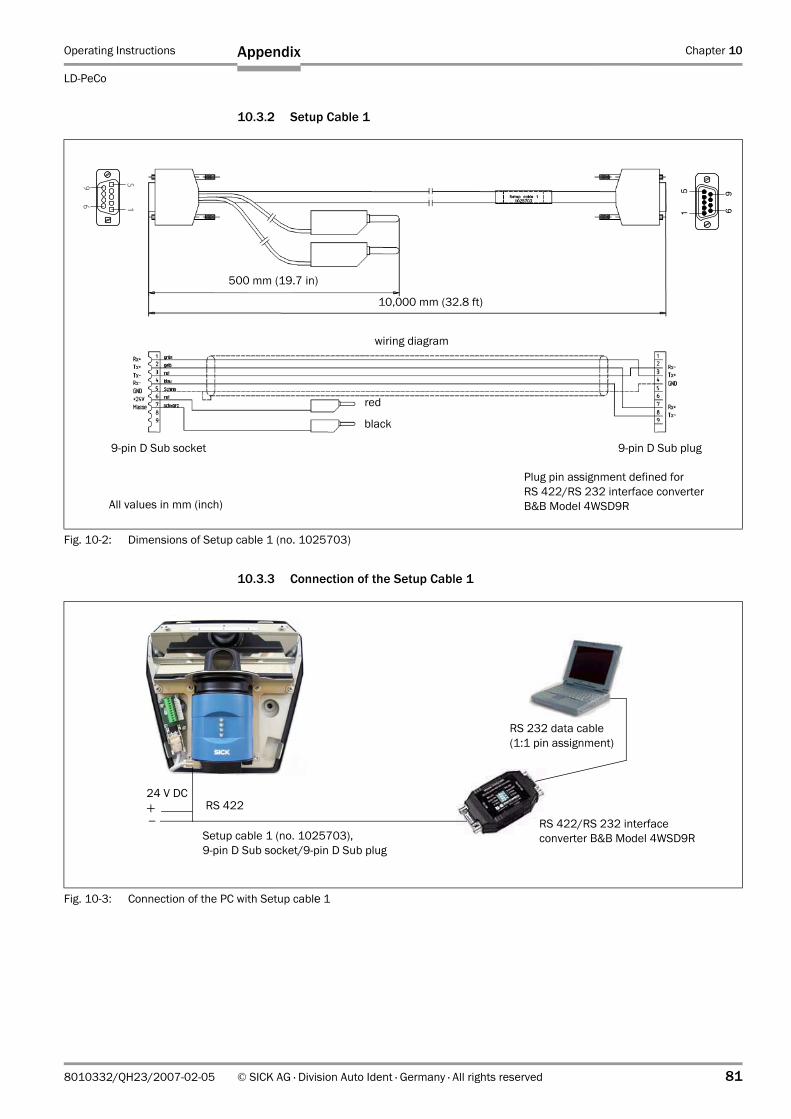
Operating Instructions Chapter 10
LD-PeCo
Appendix
8010332/QH23/2007-02-05 © SICK AG · Division Auto Ident · Germany · All rights reserved 81
10.3.2 Setup Cable 1
10.3.3 Connection of the Setup Cable 1
Fig. 10-2: Dimensions of Setup cable 1 (no. 1025703)
All values in mm (inch)
9-pin D Sub socket 9-pin D Sub plug
Plug pin assignment defined for RS 422/RS 232 interface converter B&B Model 4WSD9R
wiring diagram
500 mm (19.7 in)
10,000 mm (32.8 ft)
51
96
51
96
red
black
Fig. 10-3: Connection of the PC with Setup cable 1
+–
Setup cable 1 (no. 1025703),9-pin D Sub socket/9-pin D Sub plug
RS 422
RS 232 data cable (1:1 pin assignment)
RS 422/RS 232 interfaceconverter B&B Model 4WSD9R
24 V DC
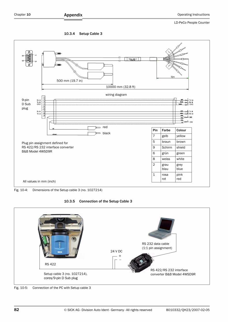
Chapter 10 Operating Instructions
LD-PeCo People Counter
82 © SICK AG · Division Auto Ident · Germany · All rights reserved 8010332/QH23/2007-02-05
Appendix
10.3.4 Setup Cable 3
10.3.5 Connection of the Setup Cable 3
Fig. 10-4: Dimensions of the Setup cable 3 (no. 1027214)
9-pinD Sub plug
All values in mm (inch)
Plug pin assignment defined for RS 422/RS 232 interface converter B&B Model 4WSD9R
500 mm (19.7 in)
10000 mm (32.8 ft)
Pin Farbe Colour
7 gelb yellow
5 braun brown
9 Schirm shield
6 grün green
8 weiss white
2 graublau
greyblue
1 rosarot
pinkred
wiring diagram
51
96
GND GND
red
black
Fig. 10-5: Connection of the PC with Setup cable 3
–+
RS 232 data cable (1:1 pin assignment)
RS 422/RS 232 interfaceconverter B&B Model 4WSD9RSetup cable 3 (no. 1027214),
cores/9-pin D Sub plug
RS 422
24 V DC
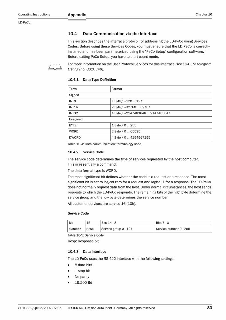
Operating Instructions Chapter 10
LD-PeCo
Appendix
8010332/QH23/2007-02-05 © SICK AG · Division Auto Ident · Germany · All rights reserved 83
10.4 Data Communication via the Interface
This section describes the interface protocol for addressing the LD-PeCo using Services Codes. Before using these Services Codes, you must ensure that the LD-PeCo is correctly installed and has been parameterized using the "PeCo Setup" configuration software. Before exiting PeCo Setup, you have to start count mode.
For more information on the User Protocol Services for this interface, see LD-OEM Telegram Listing (no. 8010348).
10.4.1 Data Type Definition
10.4.2 Service Code
The service code determines the type of services requested by the host computer.This is essentially a command.
The data format type is WORD.
The most significant bit defines whether the code is a request or a response. The most significant bit is set to logical zero for a request and logical 1 for a response. The LD-PeCo does not normally request data from the host. Under normal circumstances, the host sends requests to which the LD-PeCo responds. The remaining bits of the high byte determine the service group and the low byte determines the service number.
All customer services are service 16 (10h).
Service Code
Resp: Response bit
10.4.3 Data Interface
The LD-PeCo uses the RS 422 interface with the following settings:
• 8 data bits• 1 stop bit• No parity• 19,200 Bd
Term Format
Signed
INT8 1 Byte / –128 ... 127
INT16 2 Byte / –32768 ... 32767
INT32 4 Byte / –2147483648 ... 2147483647
Unsigned
BYTE 1 Byte / 0 ... 255
WORD 2 Byte / 0 ... 65535
DWORD 4 Byte / 0 ... 4294967295
Table 10-4: Data communication: terminology used
Bit 15 Bits 14 - 8 Bits 7 - 0
Function Resp. Service group 0 - 127 Service number 0 - 255
Table 10-5: Service Code
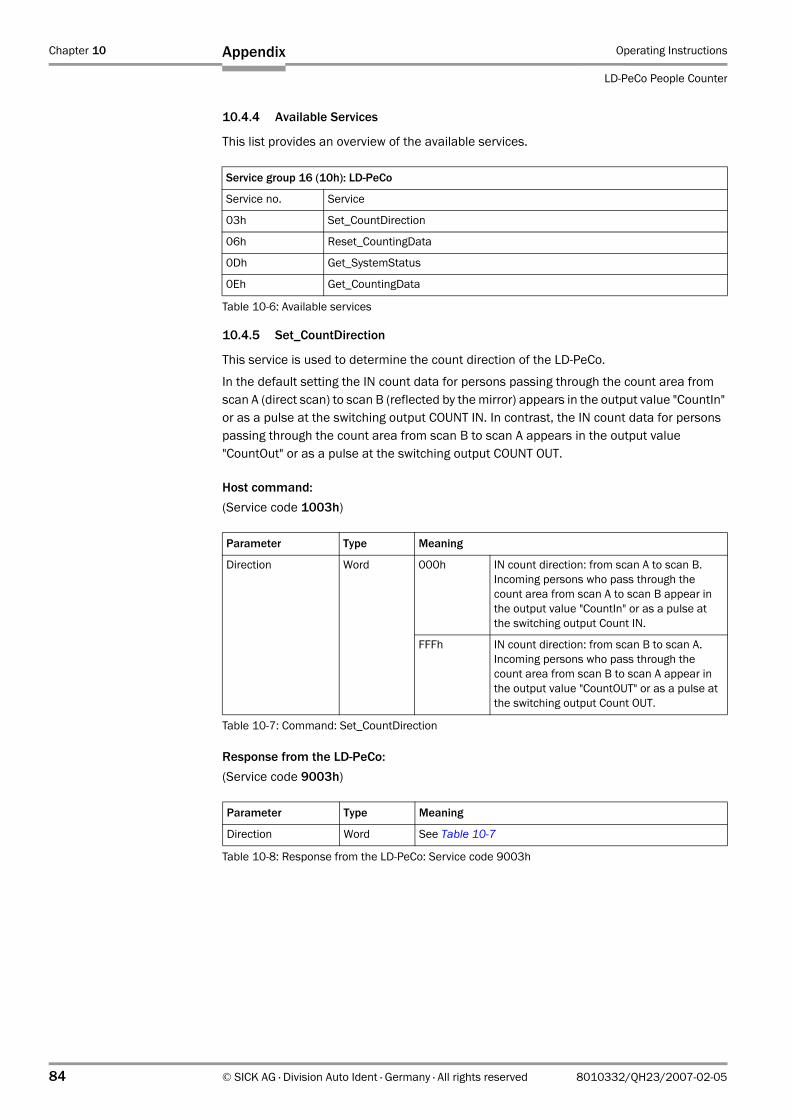
Chapter 10 Operating Instructions
LD-PeCo People Counter
84 © SICK AG · Division Auto Ident · Germany · All rights reserved 8010332/QH23/2007-02-05
Appendix
10.4.4 Available Services
This list provides an overview of the available services.
10.4.5 Set_CountDirection
This service is used to determine the count direction of the LD-PeCo.
In the default setting the IN count data for persons passing through the count area from scan A (direct scan) to scan B (reflected by the mirror) appears in the output value "CountIn" or as a pulse at the switching output COUNT IN. In contrast, the IN count data for persons passing through the count area from scan B to scan A appears in the output value "CountOut" or as a pulse at the switching output COUNT OUT.
Host command:(Service code 1003h)
Response from the LD-PeCo:(Service code 9003h)
Service group 16 (10h): LD-PeCo
Service no. Service
03h Set_CountDirection
06h Reset_CountingData
0Dh Get_SystemStatus
0Eh Get_CountingData
Table 10-6: Available services
Parameter Type Meaning
Direction Word 000h IN count direction: from scan A to scan B.Incoming persons who pass through the count area from scan A to scan B appear in the output value "CountIn" or as a pulse at the switching output Count IN.
FFFh IN count direction: from scan B to scan A.Incoming persons who pass through the count area from scan B to scan A appear in the output value "CountOUT" or as a pulse at the switching output Count OUT.
Table 10-7: Command: Set_CountDirection
Parameter Type Meaning
Direction Word See Table 10-7
Table 10-8: Response from the LD-PeCo: Service code 9003h
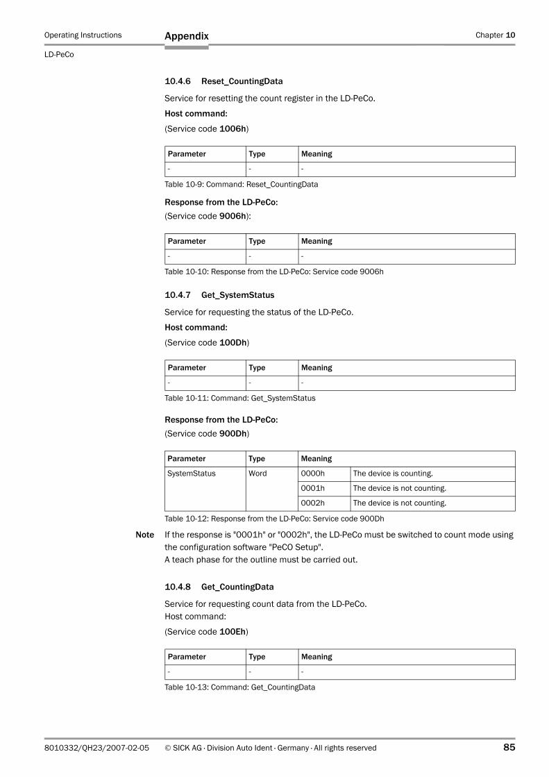
Operating Instructions Chapter 10
LD-PeCo
Appendix
8010332/QH23/2007-02-05 © SICK AG · Division Auto Ident · Germany · All rights reserved 85
10.4.6 Reset_CountingData
Service for resetting the count register in the LD-PeCo.
Host command:
(Service code 1006h)
Response from the LD-PeCo:(Service code 9006h):
10.4.7 Get_SystemStatus
Service for requesting the status of the LD-PeCo.
Host command:
(Service code 100Dh)
Response from the LD-PeCo:(Service code 900Dh)
Note If the response is "0001h" or "0002h", the LD-PeCo must be switched to count mode using the configuration software "PeCO Setup". A teach phase for the outline must be carried out.
10.4.8 Get_CountingData
Service for requesting count data from the LD-PeCo.Host command:
(Service code 100Eh)
Parameter Type Meaning
- - -
Table 10-9: Command: Reset_CountingData
Parameter Type Meaning
- - -
Table 10-10: Response from the LD-PeCo: Service code 9006h
Parameter Type Meaning
- - -
Table 10-11: Command: Get_SystemStatus
Parameter Type Meaning
SystemStatus Word 0000h The device is counting.
0001h The device is not counting.
0002h The device is not counting.
Table 10-12: Response from the LD-PeCo: Service code 900Dh
Parameter Type Meaning
- - -
Table 10-13: Command: Get_CountingData
Chapter 10 Operating Instructions
LD-PeCo People Counter
86 © SICK AG · Division Auto Ident · Germany · All rights reserved 8010332/QH23/2007-02-05
Appendix
Response from the LD-PeCo:(Service code 900Eh)
Note The count direction of the LD-PeCo can be switched using the Set_CountDirection com-mand.
10.4.9 Sample C code for for calculating a CRC sum (RS 232/RS 422)
Sample C code for calculating a CRC sum:/***************************************************************************
Project: generic projectFile: crc16c.c CRC16 calculation
Version: V0.0.1Date: 20.09.1998Compiler: Developed by: Uwe ReutherCopyright: (c) IBEO Lasertechnik GmbH 1998
**************************************************************************
Abstract: routines for calculating a 16 bits CRC signature using the generator polynom x^16 + x^12 + x^5 + 1 as recommended by the ITU.T V.42 (former CCITT); all routines use a table driven algorithm
--------------------------------------------------------------------------
Modification History:
0.0.1 20.09.1998 created***************************************************************************/
#define CRC16C_C
// includes
#include "cpu-dep.h"
//========================================================================
// local scope defines// (global scope in seperate header file: this_file.h)
//========================================================================
Parameter Type Meaning
ID Word User ID of the people counter
CountIn Word Count data for incoming persons
CountOut Word Count data for outgoing persons
Table 10-14: Response from the LD-PeCo: Service code 900Eh
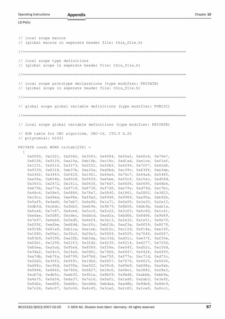
Operating Instructions Chapter 10
LD-PeCo
Appendix
8010332/QH23/2007-02-05 © SICK AG · Division Auto Ident · Germany · All rights reserved 87
// local scope macros// (global macros in seperate header file: this_file.h)
//========================================================================
// local scope type definitions// (global scope in seperate header file: this_file.h)
//========================================================================
// local scope prototype declarations (type modifier: PRIVATE)// (global scope in seperate header file: this_file.h)
//========================================================================
// global scope global variable definitions (type modifier: PUBLIC)
//========================================================================
// local scope global variable definitions (type modifier: PRIVATE)
// XOR table for CRC algorithm, CRC-16, ITU.T X.25// polynomial: h1021
PRIVATE const WORD crctab[256] = { 0x0000, 0x1021, 0x2042, 0x3063, 0x4084, 0x50a5, 0x60c6, 0x70e7, 0x8108, 0x9129, 0xa14a, 0xb16b, 0xc18c, 0xd1ad, 0xe1ce, 0xf1ef, 0x1231, 0x0210, 0x3273, 0x2252, 0x52b5, 0x4294, 0x72f7, 0x62d6, 0x9339, 0x8318, 0xb37b, 0xa35a, 0xd3bd, 0xc39c, 0xf3ff, 0xe3de, 0x2462, 0x3443, 0x0420, 0x1401, 0x64e6, 0x74c7, 0x44a4, 0x5485, 0xa56a, 0xb54b, 0x8528, 0x9509, 0xe5ee, 0xf5cf, 0xc5ac, 0xd58d, 0x3653, 0x2672, 0x1611, 0x0630, 0x76d7, 0x66f6, 0x5695, 0x46b4, 0xb75b, 0xa77a, 0x9719, 0x8738, 0xf7df, 0xe7fe, 0xd79d, 0xc7bc, 0x48c4, 0x58e5, 0x6886, 0x78a7, 0x0840, 0x1861, 0x2802, 0x3823, 0xc9cc, 0xd9ed, 0xe98e, 0xf9af, 0x8948, 0x9969, 0xa90a, 0xb92b, 0x5af5, 0x4ad4, 0x7ab7, 0x6a96, 0x1a71, 0x0a50, 0x3a33, 0x2a12, 0xdbfd, 0xcbdc, 0xfbbf, 0xeb9e, 0x9b79, 0x8b58, 0xbb3b, 0xab1a, 0x6ca6, 0x7c87, 0x4ce4, 0x5cc5, 0x2c22, 0x3c03, 0x0c60, 0x1c41, 0xedae, 0xfd8f, 0xcdec, 0xddcd, 0xad2a, 0xbd0b, 0x8d68, 0x9d49, 0x7e97, 0x6eb6, 0x5ed5, 0x4ef4, 0x3e13, 0x2e32, 0x1e51, 0x0e70, 0xff9f, 0xefbe, 0xdfdd, 0xcffc, 0xbf1b, 0xaf3a, 0x9f59, 0x8f78, 0x9188, 0x81a9, 0xb1ca, 0xa1eb, 0xd10c, 0xc12d, 0xf14e, 0xe16f, 0x1080, 0x00a1, 0x30c2, 0x20e3, 0x5004, 0x4025, 0x7046, 0x6067, 0x83b9, 0x9398, 0xa3fb, 0xb3da, 0xc33d, 0xd31c, 0xe37f, 0xf35e, 0x02b1, 0x1290, 0x22f3, 0x32d2, 0x4235, 0x5214, 0x6277, 0x7256, 0xb5ea, 0xa5cb, 0x95a8, 0x8589, 0xf56e, 0xe54f, 0xd52c, 0xc50d, 0x34e2, 0x24c3, 0x14a0, 0x0481, 0x7466, 0x6447, 0x5424, 0x4405, 0xa7db, 0xb7fa, 0x8799, 0x97b8, 0xe75f, 0xf77e, 0xc71d, 0xd73c, 0x26d3, 0x36f2, 0x0691, 0x16b0, 0x6657, 0x7676, 0x4615, 0x5634, 0xd94c, 0xc96d, 0xf90e, 0xe92f, 0x99c8, 0x89e9, 0xb98a, 0xa9ab, 0x5844, 0x4865, 0x7806, 0x6827, 0x18c0, 0x08e1, 0x3882, 0x28a3, 0xcb7d, 0xdb5c, 0xeb3f, 0xfb1e, 0x8bf9, 0x9bd8, 0xabbb, 0xbb9a, 0x4a75, 0x5a54, 0x6a37, 0x7a16, 0x0af1, 0x1ad0, 0x2ab3, 0x3a92, 0xfd2e, 0xed0f, 0xdd6c, 0xcd4d, 0xbdaa, 0xad8b, 0x9de8, 0x8dc9, 0x7c26, 0x6c07, 0x5c64, 0x4c45, 0x3ca2, 0x2c83, 0x1ce0, 0x0cc1,
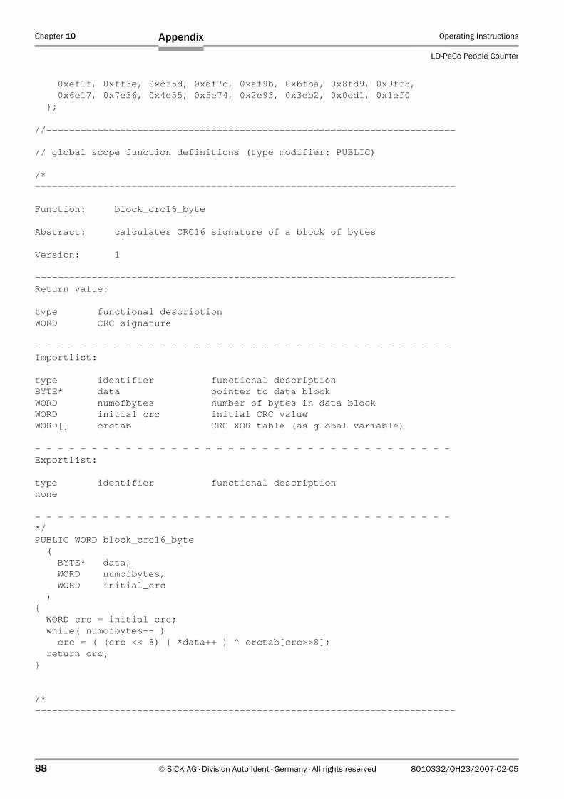
Chapter 10 Operating Instructions
LD-PeCo People Counter
88 © SICK AG · Division Auto Ident · Germany · All rights reserved 8010332/QH23/2007-02-05
Appendix
0xef1f, 0xff3e, 0xcf5d, 0xdf7c, 0xaf9b, 0xbfba, 0x8fd9, 0x9ff8, 0x6e17, 0x7e36, 0x4e55, 0x5e74, 0x2e93, 0x3eb2, 0x0ed1, 0x1ef0 };
//========================================================================
// global scope function definitions (type modifier: PUBLIC)
/*--------------------------------------------------------------------------
Function: block_crc16_byte
Abstract: calculates CRC16 signature of a block of bytes
Version: 1
--------------------------------------------------------------------------Return value:
type functional descriptionWORD CRC signature
- - - - - - - - - - - - - - - - - - - - - - - - - - - - - - - - - - - - -Importlist:
type identifier functional descriptionBYTE* data pointer to data blockWORD numofbytes number of bytes in data blockWORD initial_crc initial CRC valueWORD[] crctab CRC XOR table (as global variable)
- - - - - - - - - - - - - - - - - - - - - - - - - - - - - - - - - - - - -Exportlist:
type identifier functional descriptionnone
- - - - - - - - - - - - - - - - - - - - - - - - - - - - - - - - - - - - -*/PUBLIC WORD block_crc16_byte ( BYTE* data, WORD numofbytes, WORD initial_crc ){ WORD crc = initial_crc; while( numofbytes-- ) crc = ( (crc << 8) | *data++ ) ^ crctab[crc>>8]; return crc;}
/*--------------------------------------------------------------------------
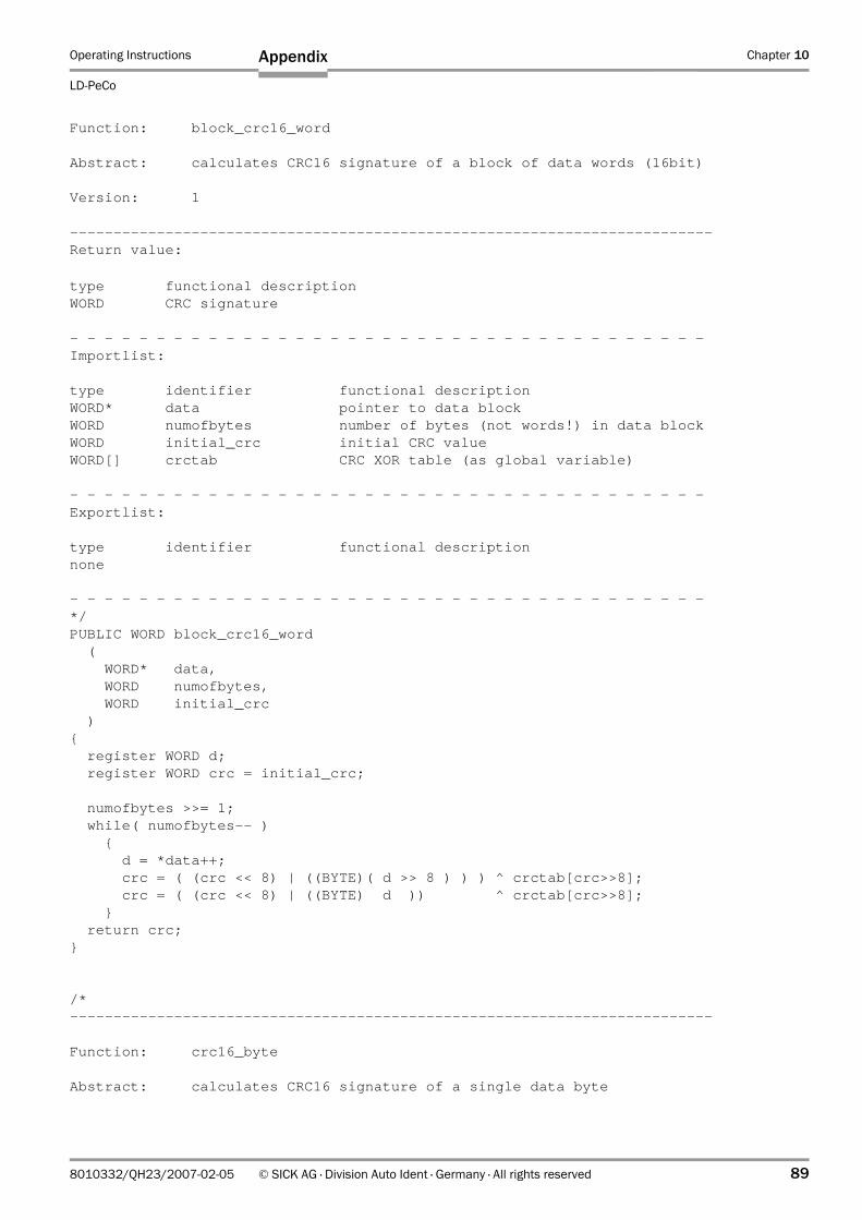
Operating Instructions Chapter 10
LD-PeCo
Appendix
8010332/QH23/2007-02-05 © SICK AG · Division Auto Ident · Germany · All rights reserved 89
Function: block_crc16_word
Abstract: calculates CRC16 signature of a block of data words (16bit)
Version: 1
--------------------------------------------------------------------------Return value:
type functional descriptionWORD CRC signature
- - - - - - - - - - - - - - - - - - - - - - - - - - - - - - - - - - - - -Importlist:
type identifier functional descriptionWORD* data pointer to data blockWORD numofbytes number of bytes (not words!) in data blockWORD initial_crc initial CRC valueWORD[] crctab CRC XOR table (as global variable)
- - - - - - - - - - - - - - - - - - - - - - - - - - - - - - - - - - - - -Exportlist:
type identifier functional descriptionnone
- - - - - - - - - - - - - - - - - - - - - - - - - - - - - - - - - - - - -*/PUBLIC WORD block_crc16_word ( WORD* data, WORD numofbytes, WORD initial_crc ){ register WORD d; register WORD crc = initial_crc;
numofbytes >>= 1; while( numofbytes-- ) { d = *data++; crc = ( (crc << 8) | ((BYTE)( d >> 8 ) ) ) ^ crctab[crc>>8]; crc = ( (crc << 8) | ((BYTE) d )) ^ crctab[crc>>8]; } return crc;}
/*--------------------------------------------------------------------------
Function: crc16_byte
Abstract: calculates CRC16 signature of a single data byte
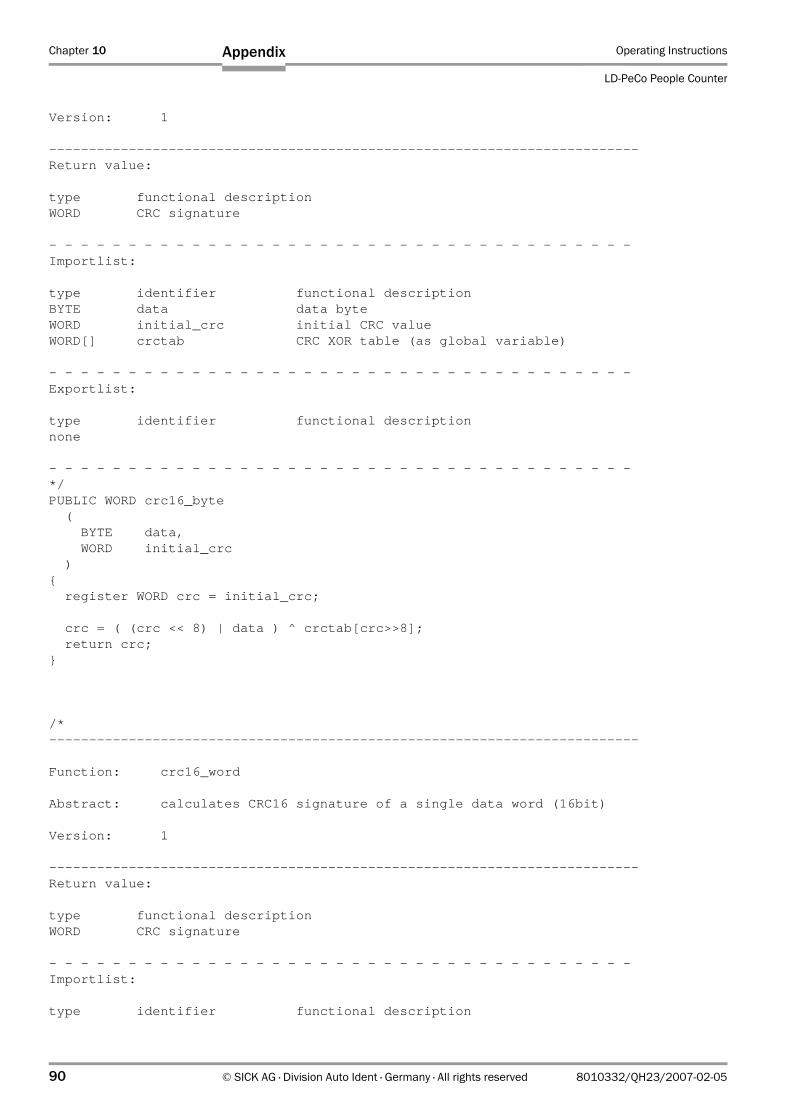
Chapter 10 Operating Instructions
LD-PeCo People Counter
90 © SICK AG · Division Auto Ident · Germany · All rights reserved 8010332/QH23/2007-02-05
Appendix
Version: 1
--------------------------------------------------------------------------Return value:
type functional descriptionWORD CRC signature
- - - - - - - - - - - - - - - - - - - - - - - - - - - - - - - - - - - - -Importlist:
type identifier functional descriptionBYTE data data byteWORD initial_crc initial CRC valueWORD[] crctab CRC XOR table (as global variable)
- - - - - - - - - - - - - - - - - - - - - - - - - - - - - - - - - - - - -Exportlist:
type identifier functional descriptionnone
- - - - - - - - - - - - - - - - - - - - - - - - - - - - - - - - - - - - -*/PUBLIC WORD crc16_byte ( BYTE data, WORD initial_crc ){ register WORD crc = initial_crc;
crc = ( (crc << 8) | data ) ^ crctab[crc>>8]; return crc;}
/*--------------------------------------------------------------------------
Function: crc16_word
Abstract: calculates CRC16 signature of a single data word (16bit)
Version: 1
--------------------------------------------------------------------------Return value:
type functional descriptionWORD CRC signature
- - - - - - - - - - - - - - - - - - - - - - - - - - - - - - - - - - - - -Importlist:
type identifier functional description
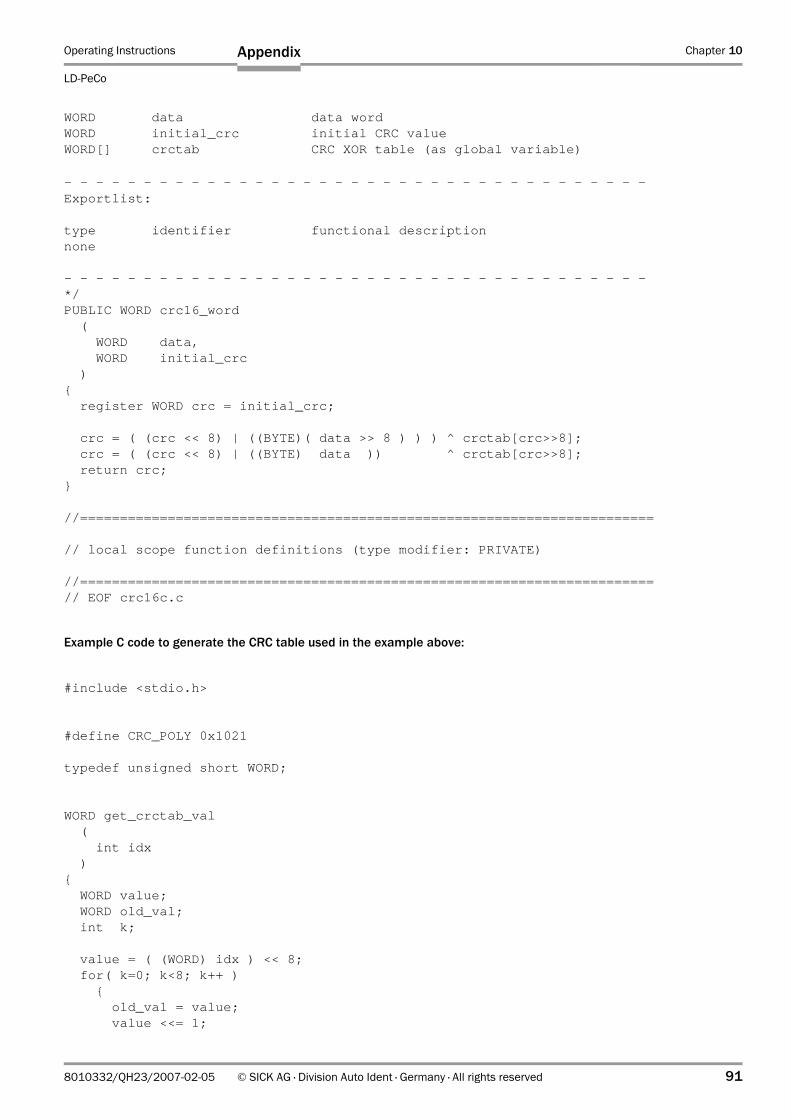
Operating Instructions Chapter 10
LD-PeCo
Appendix
8010332/QH23/2007-02-05 © SICK AG · Division Auto Ident · Germany · All rights reserved 91
WORD data data wordWORD initial_crc initial CRC valueWORD[] crctab CRC XOR table (as global variable)
- - - - - - - - - - - - - - - - - - - - - - - - - - - - - - - - - - - - -Exportlist:
type identifier functional descriptionnone
- - - - - - - - - - - - - - - - - - - - - - - - - - - - - - - - - - - - -*/PUBLIC WORD crc16_word ( WORD data, WORD initial_crc ){ register WORD crc = initial_crc;
crc = ( (crc << 8) | ((BYTE)( data >> 8 ) ) ) ^ crctab[crc>>8]; crc = ( (crc << 8) | ((BYTE) data )) ^ crctab[crc>>8]; return crc;}
//========================================================================
// local scope function definitions (type modifier: PRIVATE)
//========================================================================// EOF crc16c.c
Example C code to generate the CRC table used in the example above:
#include <stdio.h>
#define CRC_POLY 0x1021
typedef unsigned short WORD;
WORD get_crctab_val ( int idx ){ WORD value; WORD old_val; int k;
value = ( (WORD) idx ) << 8; for( k=0; k<8; k++ ) { old_val = value; value <<= 1;
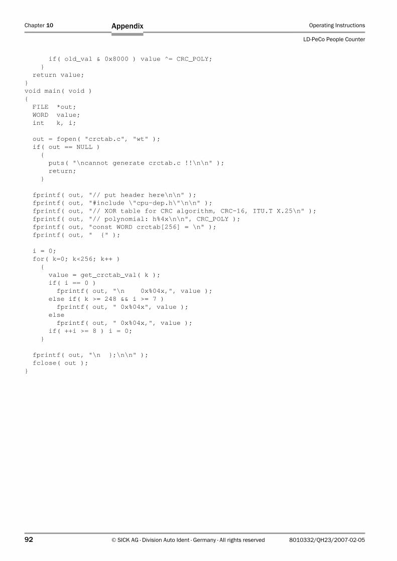
Chapter 10 Operating Instructions
LD-PeCo People Counter
92 © SICK AG · Division Auto Ident · Germany · All rights reserved 8010332/QH23/2007-02-05
Appendix
if( old_val & 0x8000 ) value ^= CRC_POLY; } return value;}void main( void ){ FILE *out; WORD value; int k, i;
out = fopen( "crctab.c", "wt" ); if( out == NULL ) { puts( "\ncannot generate crctab.c !!\n\n" ); return; }
fprintf( out, "// put header here\n\n" ); fprintf( out, "#include \"cpu-dep.h\"\n\n" ); fprintf( out, "// XOR table for CRC algorithm, CRC-16, ITU.T X.25\n" ); fprintf( out, "// polynomial: h%4x\n\n", CRC_POLY ); fprintf( out, "const WORD crctab[256] = \n" ); fprintf( out, " {" );
i = 0; for( k=0; k<256; k++ ) { value = get_crctab_val( k ); if( i == 0 ) fprintf( out, "\n 0x%04x,", value ); else if( k >= 248 && i >= 7 ) fprintf( out, " 0x%04x", value ); else fprintf( out, " 0x%04x,", value ); if( ++i >= 8 ) i = 0; }
fprintf( out, "\n };\n\n" ); fclose( out );}
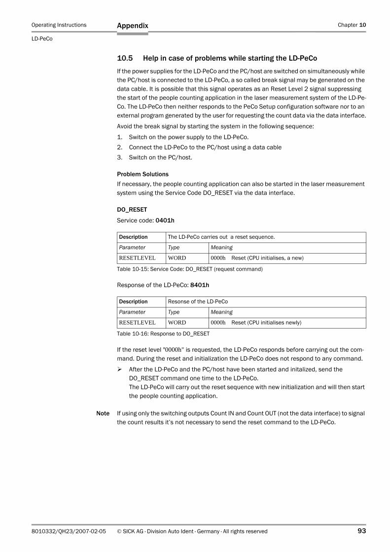
Operating Instructions Chapter 10
LD-PeCo
Appendix
8010332/QH23/2007-02-05 © SICK AG · Division Auto Ident · Germany · All rights reserved 93
10.5 Help in case of problems while starting the LD-PeCo
If the power supplies for the LD-PeCo and the PC/host are switched on simultaneously while the PC/host is connected to the LD-PeCo, a so called break signal may be generated on the data cable. It is possible that this signal operates as an Reset Level 2 signal suppressing the start of the people counting application in the laser measurement system of the LD-Pe-Co. The LD-PeCo then neither responds to the PeCo Setup configuration software nor to an external program generated by the user for requesting the count data via the data interface.
Avoid the break signal by starting the system in the following sequence:
1. Switch on the power supply to the LD-PeCo.2. Connect the LD-PeCo to the PC/host using a data cable3. Switch on the PC/host.
Problem SolutionsIf necessary, the people counting application can also be started in the laser measurement system using the Service Code DO_RESET via the data interface.
DO_RESET
Service code: 0401h
Response of the LD-PeCo: 8401h
If the reset level "0000h" is requested, the LD-PeCo responds before carrying out the com-mand. During the reset and initialization the LD-PeCo does not respond to any command.
After the LD-PeCo and the PC/host have been started and initalized, send the DO_RESET command one time to the LD-PeCo.The LD-PeCo will carry out the reset sequence with new initialization and will then start the people counting application.
Note If using only the switching outputs Count IN and Count OUT (not the data interface) to signal the count results it’s not necessary to send the reset command to the LD-PeCo.
Description The LD-PeCo carries out a reset sequence.
Parameter Type Meaning
RESETLEVEL WORD 0000h Reset (CPU initialises, a new)
Table 10-15: Service Code: DO_RESET (request command)
Description Resonse of the LD-PeCo
Parameter Type Meaning
RESETLEVEL WORD 0000h Reset (CPU initialises newly)
Table 10-16: Response to DO_RESET
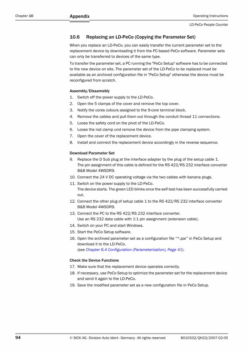
Chapter 10 Operating Instructions
LD-PeCo People Counter
94 © SICK AG · Division Auto Ident · Germany · All rights reserved 8010332/QH23/2007-02-05
Appendix
10.6 Replacing an LD-PeCo (Copying the Parameter Set)
When you replace an LD-PeCo, you can easily transfer the current parameter set to the replacement device by downloading it from the PC-based PeCo software. Parameter sets can only be transferred to devices of the same type.
To transfer the parameter set, a PC running the "PeCo Setup" software has to be connected to the new device on site. The parameter set of the LD-PeCo to be replaced must be available as an archived configuration file in "PeCo Setup" otherwise the device must be reconfigured from scratch.
Assembly/Dissamebly1. Switch off the power supply to the LD-PeCo.2. Open the 5 clamps of the cover and remove the top cover. 3. Notify the cores colours assigned to the 9-core terminal block. 4. Remove the cables and pull them out through the conduit thread 11 connections.5. Loose the safety cord on the pivot of the LD-PeCo.6. Loose the rod clamp und remove the device from the pipe clamping system.7. Open the cover of the replacement device.8. Install and connect the replacement device accordingly in the reverse sequence.
Download Parameter Set9. Replace the D Sub plug at the interface adapter by the plug of the setup cable 1.
The pin assignment of this cable is defined for the RS 422/RS 232 interface converter B&B Model 4WSDR9.
10. Connect the 24 V DC operating voltage via the two cables with banana plugs.11. Switch on the power supply to the LD-PeCo.
The device starts. The green LED blinks once the self-test has been successfully carried out.
12. Connect the other plug of setup cable 1 to the RS 422/RS 232 interface converter B&B Model 4WSDR9.
13. Connect the PC to the RS 422/RS 232 interface converter.Use an RS 232 data cable with 1:1 pin assignment (extension cable).
14. Switch on your PC and start Windows.15. Start the PeCo Setup software.16. Open the archived parameter set as a configuration file “*.par” in PeCo Setup and
download it to the LD-PeCo. (see Chapter 6.4 Configuration (Parameterization), Page 41).
Check the Device Functions17. Make sure that the replacement device operates correctly. 18. If necessary, use PeCo Setup to optimize the parameter set for the replacement device
and send it again to the LD-PeCo.19. Save the modified parameter set as a new configuration file in PeCo Setup.
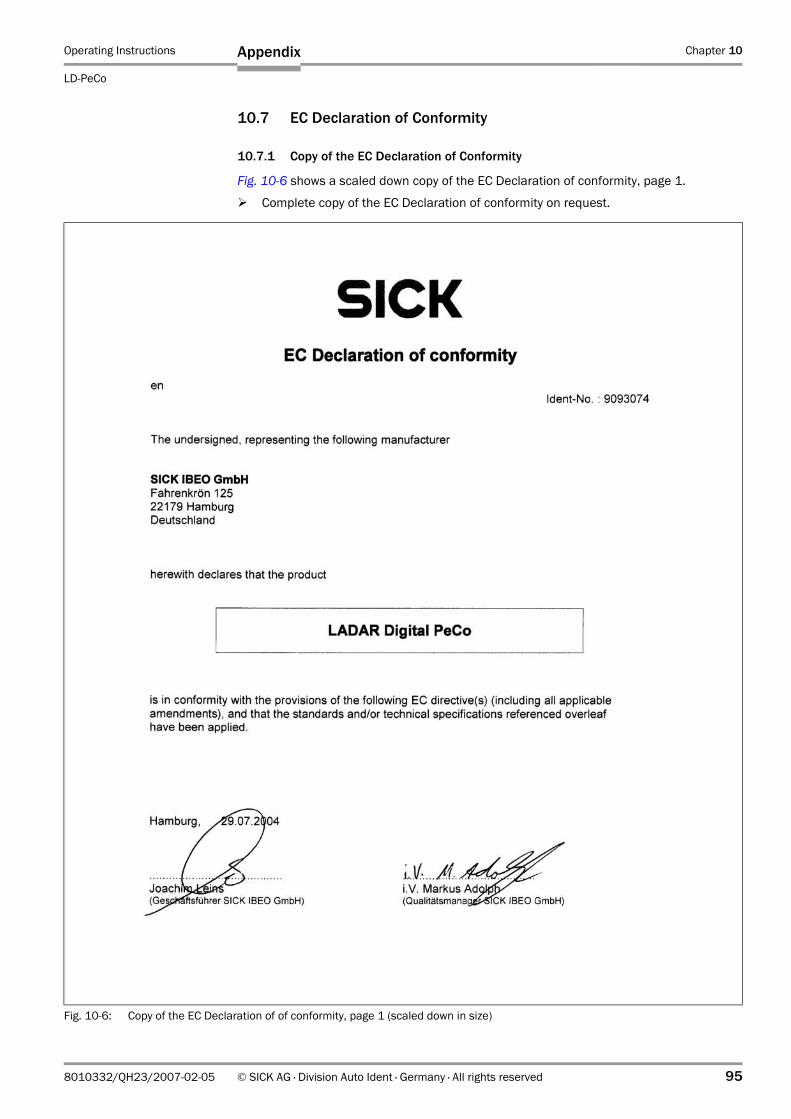
Operating Instructions Chapter 10
LD-PeCo
Appendix
8010332/QH23/2007-02-05 © SICK AG · Division Auto Ident · Germany · All rights reserved 95
10.7 EC Declaration of Conformity
10.7.1 Copy of the EC Declaration of Conformity
Fig. 10-6 shows a scaled down copy of the EC Declaration of conformity, page 1.
Complete copy of the EC Declaration of conformity on request.
Fig. 10-6: Copy of the EC Declaration of of conformity, page 1 (scaled down in size)
SICK AG | Waldkirch | Germany | www.sick.com
AustraliaPhone+61394974100 1800334802–tollfreeE-Mail [email protected]
Belgium/LuxembourgPhone+32(0)[email protected]
Ceská [email protected]
Españ[email protected]
Great BritainPhone+44(0)[email protected]
IndiaPhone+91–22–[email protected]
JapanPhone+81(0)[email protected]
NederlandsPhone+31(0)[email protected]
Norge [email protected]
ÖsterreichPhone+43(0)[email protected]
Republic of KoreaPhone+82-27866321/[email protected]
Republika SlowenijaPhone+386(0)[email protected]
USA/Canada/MéxicoPhone+1(952)941-6780 1800-325-7425–[email protected]
Morerepresentativesandagenciesinallmajorindustrialnationsatwww.sick.com
8010
332/
QH
23/2
007-
02-0
5. 5
M/T
R <P
M6.
5/FM
7.0/
PDF>
/VD
.P
rinte
din
Ger
man
y.
Subj
ectt
och
ange
with
outn
otic
e.
The
spec
ified
pro
duct
feat
ures
and
tech
nica
ldat
ado
not
repr
esen
tany
gua
rant
ee.
05
Afti
nt58