Embed Size (px)
Citation preview

11 1§ 11 fl ! ! .J.1
AD-A197 957 .-
... .....
LCWY(..
ItUN&VD
-~ -- v
~ .;N ~4 4 E.LECTE
AU 15 I
Illm JI, CENTE
011570
*~[~2Ir
-- C%
.' -

-4 app'ive A*
-. A 1We ts. 711 x.~A~~
yvf 40 has Nc hiuw d septvd
Of Iyuwstob4 reoe rute A~ mln
d~fM-., Diretoat thf Ilan be returned

-S
UNCLASSIFIED *SECURITY CLASSIFICATION OF THIS PAGE _ _ 19 9S
SForm Approved
REPORT DOCUMENTATION PAGE OMBNo. 0704-0188
la. REPORT SECURITY CLASSIFICATION b RESTRICTIVE MARKINGS
UNCLASSIFIED N/A2. SECURITY CLASSIFCATION AUTHORITY 3. DISTRIBUTION /AVAILABILITY OF REPORT
NA Approved for public release; distribution2b. DECLASSICATION / DOWNGRADING SCHEDULE u l m t dN/Aunlimited.
4. PERFORMING ORGANIZATION REPORT NUMBER(S) 5. MONITORING ORGANIZATION REPORT NUMBER(S)
N/A RADC-TR-88-11, Vol III (of eight)
6a. NAME OF PERFORMING ORGANIZATION 6b. OFFICE SYMBOL 7a. NAME OF MONITORING ORGANIZATION
Northeast Artificial (If applicable) Rome Air Development Center (COES)Intelligence Consortium (NAIC)
6c. ADDRESS (City, State, and ZIPCode) 7b. ADDRESS (City, State, and ZIP Code)
409 Link HallSyracuse University Griffiss AFB NY 13441-5700
Syracuse NY 13244-1240
8a. NAME OF FUNDING/SPONSORING 8b. OFFICE SYMBOL 9 PROCUREMENT INSTRUMENT IDENTIFiCATION NUMBERORGANIZATION (If applicable) F30602-85-C-0008
Rome Air Development Center (COES)
8c. ADDRESS (City, State, and ZIP Code) 10 SOURCE OF FUNDING NUMBERS
Griffiss AFB NY 13441-5700 PROGRAM PROJECT TASK WORK UNITELEMENT NO. NO NO ACCESSION NO62702F 5581 27 13
____________________________________ I (Over)11. TITLE (include Security Classification)
NORTHEAST ARTIFICIAL INTELLIGENCE CONSORTIUM ANNUAL REPORT 1986
Distributed Artificial Intelligence for Communication Network Management
12. PERSONAL AUTHOR(S)
Robert A. Meer Susan E. Conr113. TYPE OF REPORT 13b TIME COVERED 14. DATE OF REPORT (Year, Month, Day) 15 PAGE COUNT
Interim FROM Jan 86 TO Dec 86 June 1988 52
16. SUPPLEMENTARY NOTATION
This effort was performed as a subcontract by Clarkson University to Syracuse University,Office of Sponsored Programs. (See Reverse)
17. COSATI CODES I8. SUBJECT TERMS (Continue on reverse if necessary and identify by block number)
FIELD GROUP SUB-GROUP Artificial Intelligence Distributed Planning
12 05 Distributed Artificial Intelligence, Communications Network
Simulation, (Over)
19. ABSTRACT (-ewitnue o revers- if ncessary ard kienti by block number)
The Northeast Artificial Intelligence Consortiu5)(NAIC) was created by the Air Force SystemsCommand, Rome Air Development Center, and the--ffice of Scientific Research,. Its purposeis t~conduct pertinent research in artificial intelligence and -t perform%,activities
ancillary to this research. This report describes progress that has been made in the
second year of the existence of the *A4-on the technical research tasks undertaken at the
member universities. The topics covered in general are: versatile expert system for
equipment maintenance, distributed AT for communications system control, automatic photo
interpretation, time-oriented problem solving, speech understanding systems, knowledgebase maintenance, hardware architectures for very large systems, knowledge-based reasoningand planning, and a knowledge acquisition, assistance and explanation system. The specific
topic for this volume is the use of knowledge-based systems for communications network
management apd control via an architecture for a diversely distributed multi-agent system. %
20 DISTRIBUTION /AVAILABILITY OF ABSTRACT 21 ABSTRACT SECURITY CLASSIFI('ATIONX
DO Form 1473, JUN 86 Previous editions are obsolete SECURITY CLASSIFICATION OF THIS PAGE
UNCLASSIFIED
.'4
~~~~~ L, _N' 7 -- siyo.

UNCLASSIFIED
i
Item 10. SOURCE OF FUNDING NUMBERS (Continued)
Program Element Project Task Work Unit
Number Number Number Number
62702F 4594 18 E2
61101F LDFP 15 C4
61102F 2304 J5 01
33126F 2155 02 10
Item 18. SUBJECT TERMS (Continued)
S---- Graphical User Interface,'
Knowledge4based Reasoning.
Item 16. SUPPLEMENTARY NOTATION (Continued)
This effort was funded partially by the Laboratory Directors' Fund.
S
Access9ion F~or
NTIS GRA&IDTIC TAB
,Unainounced
JU~t1fioatL.UL- - -By -.~ -
DistribtIt.fn/
r
I
JUvall and/or
Dist Special
I' I.__________UNCLASSI FIED
% Y % %*%11.% - ; - -A .

S
TABLE OF CONTENTS
LIST OF FIGURES 3-2
3.1 Introduction 3-3
3.2 Distributed Simulation Environment 3-53.2.1 Introduction 3-53.2.2 System Structure 3-53.2.3 Simulation Strategy 3-83.2.4 SIMULACT'S User Interface 3-103.2.5 Summary 3-12
3.3 Graphical User Interface 3-133.3.1 Introduction 3-133.3.2 Application Domain Features 3-143.3.3 Knowledge Base Architecture 3-153.3.4 Design Overview 3-163.3.5 Design Implementation 3-193.3.6 GUS Architectural Design 3-213.3.7 Evaluation 3-243.3.8 Comparison With Existing Tools 3-26
3.4 Multistage Negotiation In Distributed Planning 3-283.4.1 Introduction 3-283.4.2 Motivation For Multistage Negotiation 3-283.4.3 A Specific Application and an Example 3-293.4.4 Model Of Problem Solving 3-343.4.5 Multistage Negotiation 3-37 ,.3.4.6 Concluding Remarks 3-42
Bibliography 3-44
3- 1
for, r Irr I

LIST OF FIGURES
Figure 3-1 SIMULACT's Structure 3-6Figure 3-2 Simulation Coordination 3-10Figure 3-3 Classification of Knowledge Found in the System 3-15
Knowledge BaseFigure 3-4 Objects and Object Type Classifications 3-17Figure 3-5 Functionality in GUS 3-18Figure 3-6 Example Network 3-31Figure 3-7 Global Search Space 3-35Figure 3-8 Local Feasibility Trees 3-36
S
3-2
.UN; %

3.1 Introduction
The work described here is based on the completion of the second year of a fiveyear research program designed to answer fundamental questions about the use ofknowledge-based systems in communications network management and control. We havedeveloped an architecture for a diversely distributed, multi-agent system in which eachcomponent is a specialized and localized knowledge-based system designed to provideassistance to the human operator and to cooperate with similar such systems performingother functions and/or located in physically separate facilities. This view of the roleof a knowledge-based system as a collection of autonomous, cooperating independentspecialists is an important characteristic of our approach to distributed networkmanagement.
Modem communications systems, such as the Defense Communications System (DCS),are highly complex collections of equipment and transmission media which currentlyrequire, in varying degrees, human intervention for control. The control task is onewhich requires extensive, specialized knowledge and the ability to reason using thisknowledge in solving problems. In the past, system control has been a difficult area toautomate because the number of situations which may arise and alternative solutionsavailable are very large, and thus traditional, purely algorithmic approaches have beenfound lacking.
In our work we have developed a model for communications system management,based on the DCS in Europe. From an in-depth analysis of the problem domain, includingfield site visits and interviews with operating personnel, we have identified specificproblem solving tasks which we believe are suitable for a knowledge-based system. Wefound three fundamental kinds of knowledge-based problem solving activities required:(1) data interpretation and situation assessment; (2) diagnosis and fault isolation; and(3) planning for resource allocation. In addition to this functional distribution ofproblem solving activities, our model requires a spatial distribution of decision makingas well. We have designed an architecture to meet these requirements which consists of 0a distributed knowledge-based system built on a community of problem solving agents.Each agent is a functionally specialized knowledge-based problem solver at a specificsite. These agents coordinate and cooperate to solve global problems among themselves,crossing functional or spatial boundaries as required.
0An important feature of this architecture is the concept of a local, shared
knowledge base. Although each problem solving agent has its own, private knowledgeabout how to perform the specialized problem solving activity for which it isresponsible, much of the knowledge needed for problem solving is related to thecommunication system. This knowledge describes the network structure and organization,the details of different equipment types, and what is known about the current state ofthe communications system. Since this knowledge is spatially distributed, and sharedamong the other functional agents at the same local site, it is implemented as a singlelocal knowledge base for each site. An implicit assumption is that each control siteonly maintains detailed knowledge about the communications equipment and circuits whichare within its region of responsibility, and the local knowledge base contains only verylimited knowledge about the system outside the local area.
3-3 pIlIl
At the present time we have implemented a Distributed Al System (DAISY) testbedwhich supports simulation of multiple agents on a group of heterogeneous LISPprocessors. The DAISY testbed incorporates two system building tools which we developedduring this effort. SIMULACT is a generic tool for simulating multiple actors in adistributed Al system and is described in section 3.2. In section 3.3 we describe agraphical user interface (GUS) which assists a user in capturing structural knowledgeabout a communications system. We have also made significant progress in designing adistributed planner for resource allocation. This work has led to the formulation of anew distributed problem solving paradigm we call Multistage Negotiation. Section 3.4illustrates the operation of multistage negotiation with an example problem involvingthe restoration of communications service following an outage.
Y
3-4
% % %,% or
J- P L w
00

3.2 Distributed Simulation Environment 3
3.2.1 Introduction
In this section we discuss SIMULACT, a tool we have developed for simulating andobserving the behavior of networks of distributed systems. Unlike many other systemsfor simulating distributed environments [2, 6, 19], the goal of our system is notprimarily one of achieving speed of execution through parallelism. Instead, it isassumed that the application is inherently distributed, and a natural framework forinvestigating network behavior is provided. Our system is useful in simulatingdistributed systems in which processing agents collectively work together towards "
satisfaction of one or more goals. It is assumed that each agent runs asynchronouslyand can only communicate with neighboring agents through an exchange of messages. Inaddition, the activities performed by each agent are assumed to be complex, so that theparallelism is coarse grained.
SIMULACT is written in ZetaLisp and extended Common Lisp. It currently runs onthe SYMBOLICS 3600 and the TI EXPLORER Lisp machines. Our implementation makesextensive use of flavors to improve data encapsulation and facilitate the modeling ofenvironments in which a group of semiautonomous processes do not share common memory.
.3.2.2 System Structure
SIMULACT is a distributed time driven simulator capable of achieving improved runtime performance through the application of event driven and parallel programmingstrategies. In this subsection, we describe the major components of SIMULACT at a highlevel. A discussion of the simulation strategy employed by SIMULACT and some of theimplementation details are found in [15].
SIMULACT has a modular structure comprised of four component types: Actors,Ghosts, Directors, and an Executive Director (see Figure 3-1). Actors play the part ofprocessing agents in a distributed system. Multiple instances of agents of the sametype in a system are easily incorporated in SIMULACT without requiring any special codedevelopment on the part of the user. Ghosts generate information about the environmentthat naturally occurs in a "real" distributed system and do not represent any physicalcomponent of the distributed system being simulated. The Director is responsible forcontrolling the simulation and all interactions between Actors and Ghosts at each host(there is one Director for each Lisp machine in the network). Finally, the ExecutiveDirector coordinates a simulation distributed over a network of Lisp machines. In Vgeneral, Actors play the role of the entities being simulated, while the Director staysbackstage, attempting to get realistic performance from the Actors. In the paragraphswhich follow, the role of each of these system components is described in more detail.
Actors in SIMULACT closely resemble the entities which Hewitt calls Actors [12].Hewitt's Actors are self contained entities which work cooperatively in performingcomputation and can only be accessed via message passing. Sending and receivingmessages are considered to be atomic operations, and messages are accepted one at a time Sin the order they arrive. Each message, when evaluated, may influence an Actor to
3-5
' , % -% % %.-.

ATR ACTOR GHOST GHOST
n m
a) Host Level Structure
EXECUTIVE DIRECTOR
Grp Messenger
DIRECTOR I DIRECTOR 2
ACTOR 'ACTOR GHOST GHOST 4ACTOR ACTOR GHOST GHOST
b) Network Level Structure
Figure 3-1 SIMULACT's Structure
3-6

create new Actors, send new communications to other Actors, or to specify the manner inwhich it will handle new messages.
In SIMULACT, Actors are also self contained and represent the fundamental Sstructure used to simulate concurrency. Our Actors communicate asynchronously byrouting messages through the Director. Each Actor in SIMULACT has a "stagename" that isknown by its Director and is used in routing these messages. When a Director is askedto transmit a message, it does so by either updating the appropriate Actor's "mailbox"directly, or routing the message to the appropriate Lisp machine through the ExecutiveDirector (if the destination agent resides on a different host machine in the network).When an Actor decides to read its mailbox, it has the responsibility of preserving theincoming messages and choosing which one, if any, it will currently respond to. Thecontent and form of messages are independent of SIMULACT, and are determined by theapplication programmer.
The connectivity of Actors may be 'ixed or dynamic depending on the physicalsystem being simulated. In a rigidly connected system, each Actor knows the stagenamesof Actors with whom it can directly communicate. It is also possible for an Actor toknow of the existence of a distant Actor to whom it can indirectly send a message. In " .simulations where the physical connectivity is allowed to change depending on thecurrent state of the system, SIMULACT provides the capability of generating and managingappropriate stagenames on demand. This is analogous to situations in which Hewitt'sActors spawn new Actors.
One issue which must be addressed in any simulation is the representation ofevents which occur in the external world and may have impact on the state of the __
simulation. Examples include external inputs to the 3imulation from its "globalenvironment" as well as inputs which reflect the "side effects" of the simulated , ,system's activity. Ghosts give the application programmer a facility for injectingthese factors into the simulation. For example, a Ghost can use its own event-list to .send an Actor a message signaling the occurence of some event at a given time. AGhost's event-list can easily be altered to investigate the performance of the simulated .system in subsequent runs. Ghosts can also be used to inject noise, or wronginformation into the simulated system so that issues associated with robustness can be -. ',..,
easily investigated.
Actors and Ghosts are referred to as Cast members in SIMULACT, since they are verysimilar in structure. Each Cast member has a top level function associated with itreferred to as a "script function". The script function is written by the applicationprogrammer and is invoked by SIMULACT to initiate each Cast member's simulation.Differences between these two cast types are specified (in implementation) throughdaemons associated with the Actor and Ghost data types. These differences arise fromthe fact that Actors represen! the physical system and must be carefully controlled toachieve a realistic simulation. On the other hand, Ghos, arc considered part of theoverhead associated with the simulation.
Since SIMULACT is a distributed simulator which runs on a network of Lispmachines, mechanisms for controlling activity among several agents resident on a single S
3- 7
n;.0A r

host must be provided. Each host in the network uses a Director to control the activityof Cast members residing at that site, and to route messages to and from these Castmembers. Inter-host coordination is managed by the Executive Director.
The Director delegates the task of controlling Cast member activity to the Grip.The job of routing messages to and from Cast members is given to the Messenger. Theresponsibilities of the Grip range from setting up and initializing each Cast member'slocal environment to managing and executing the Actor and Ghost queues. The Messengeronly deals with the delivery and routing of messages. When a message is sent, it isplaced directly into the Messenger's "message-center". During each time frame, the Gripinvokes the Messenger to distribute the mail. Whenever the destination stagename isknown to the Messenger, the message is placed in the appropriate Cast member's mailbox.Otherwise, it is passed to the Executive Director's Messenger and routed to theappropriate Host.
S
There is one Executive Director in SIMULACT which coordinates the entiresimulation over a distributed network. The Executive Director provides the link betweenDirectors necessary for inter-machine communications, it directs each grip so thatsynchronization throughout the network is maintained, and it handles the interfacebetween the user and SIMULACT.
3.2.3 Simulation Strategy
In this subsection, we describe the simulation strategy employed by SIMULACTwithout giving extensive details regarding implementation. In SIMULACT, the components f -,of the physical system being simulated are modeled solely by Actors. Only Actors needto be considered when determining the current "real time" associated with a simulation.For this reason, each instance of an Actor is implemented as a process on a Lispmachine. In general, an Actor's script function is written by the applicationprogrammer so that it never "terminates". At any given time, the amount of CPU timespent by the Lisp machine in executing an Actor's script function can be determined.This CPU time, along with the Actor's CPW time (Controlled Program Wait time, or thetime spent idle but waiting for response to messages sent), is used in computing theela ,ed real time for a given Actor.
A Director is responsible for controlling the simulation on the host machine whereit resides. Each Director has two local state variables referred to as actors and •ghosts. The scheduling queue used by SIMULACT in controlling the simulation (relativeto each host) is comprised of these two components. The Director advances thesimulation locally by one time frame as follows:
(1) When the Executive Director signals the Grip to begin executing a time frame,the Director's current elapsed time is set to the minimum elapsed time of itsdependent Actors.
(2) The C rip invokes each Ghost in the ghost queue in a round robin fashion fortheir current effect on the simulation.
3-8
: g"- % .-: . .,-,_.-,.-.. ., ,. . ...-.-.- -.,_,...... ...-. .,....... . .. -..,.. -. ,.,,= ' l I " M . = . " M " * t " * * .% N '.
•" *
•-"""
•-%
ot

(3) The Messenger distrutes all messages present in its message center. Anymessage with an unki.own destination is routed to the Executive Director.
(4) The Grip signals the Executive Director that it has completed step (3) and -enters a wait state. This wait state is maintained until all Grips havefinished this step.
(5) When the Executive Director signals the Grip to continue, each Actor is removedfrom the actor queue in a round robin fashion, and
- if it is active, it is allowed to run for one time frame.- if it is not active, its CPW time is incremented by one time frame.
(6) Go to (1).
From a network perspective the simulation can be viewed as follows: S
(1) SIMULACT's current elapsed time has value (n)(time-frame).
(2) The Executive Director sends each Director a message to begin executing a timeframe.
(3) The Executive Director collects all inter-machine messages from each Director,and distributes them accordingly.
(4) The Executive Director sends each Director a message to continue executing thecurrent time frame.
(5) SIMULACT's current elapsed time is incremented by one time frame (n=n+l).
(6) Go to (1).
Notice that for each time frame, messages are distributed after all the Ghosts have beeninvoked. These messages include the current ones just generated by the Ghosts, plus anyActor messages generated during the previous time frame. It is the responsibility ofeach Cast member to read its mailbox in order to receive these messages, which aretagged with the time of origination. If required, the application programmer can A,
specify a delivery delay time appropriate for the physical system being simulated.
An example of SIMULACT's simulation strategy is depicted in Figure 3-2. Thesimulation consists of six Actors (A, B, C, D, E, F) distributed over two hosts. Duringthe first time frame, Host 1 allows Actors A, B, and C to run for one time frame each.Likewise, Actors D, E, and F each run for one time frame on Host 2. Neglecting alloverhead (including Ghosts) one simulated time frame requires three time frame units toexecute. After both machines have completed execution of the current time frame, thenext time frame begins.
Allowable time frames in SIMULACT may range from one sixtieth of a second to ,
several seconds. The user specifies his own time frame during system initialization.
3-9

WH
HOST I HOST 2
A Dt= 1 Time
B E Framet=2 1
C F
t=3 '
A Dt=4 Time
B E Frame
t=5 2
C F
t=7 -- Time
B E Frame
t=8
C Ft=9 ,---
Figure 3-2 Simulation Coordination
3.2.4 SIMULACT'S User Interface
SIMULACT provides the application programmer with a tool for simulating andinvestigating the behavior of networks of agents. Application code is written for eachagent in Lisp as though there were as many machines in the network as agents in thesystem.
SIMULACT has three initialization modes: New World Generation, Old WorldLoad, and Current World Edit. The generation of a new world in SIMULACT is a menudriven process in which the application programmer specifies the details required to dothe simulation. This includes initializing the Executive Director, the Director on eachhost, and every Cast member. Once the generation of a new world in SIIMURLACT has beencompleted, the user has the option of saving it to disk. The Old World Load facility
3-10

* N~ t
subsequently loads this information into SIMULACT, without involving the user. TheCurrent World Edit option loads an old world into SIMULACT, and then allows the user toedit it. This is a convenient mechanism for running subsequent simulations with minoralterations. s
Initializing the Executive Director configures the Lisp machine network and setsup the user interface. The user must specify the number of hosts involved in thesimulation, and set such parameters as the time frame size and the simulated starttime. This allows SIMULACT to initialize the gauge facility, which is that part of theuser interface which provides control over the simulation (mode select gauge), displaysthe current simulated time (elapsed time gauge), and allows the application programmerto monitor domain specific characteristics. The initialization of the ExecutiveDirector is not complete until all Directors are initialized.
Director initialization is done locally at each host and includes initializing the SCast and their environments. After each Cast member is initialized, the Messenger makesan entry into its "address-book". The address-book is an association list linking aCast member's stagename to its corresponding Lisp object, and is used to route memos.Director initialization also alters the host machine's operating system to accomodatethe specified time frame size.
Each Cast member runs in its own package [22], so it cannot directly access anyother Cast member's local state. This ensures that all communications among Castmembers are directed through SIMULACT. Each Cast member has one or more initializationfiles associated with it. These files contain code written by the applicationprogrammer describing all activities performed by the Cast member. The Cast member'sscript function must be contained in this code.
Each Cast member is also given a stagename during initialization. As has beenmentioned, these stagenames are used by the Director's Messenger in routing memos. Inaddition, each cast member is associated with a window pane on the console's screenduring initialization. The typical user interface functions (i.e., print, read, etc.)are shadowed bo that the user can access each cast member easily through these windows.The collection of all Cast panes makes up the Director's window frame. SIMULACT'sinterface allows the user to display one Director frame at a time. It also notifies theuser when a deexposed frame needs attention.
Since each Cast member maintains its own independent local state, multipleinstances of the same Cast type can lead to multiple copies of code. To reduce thiscostly overhead SIMULACT allows Cast members to use Support packages. A Supportpackage contains code that can be accessed by several Cast members, thus reducing memoryrequirements. As in any shared memory system, a problem could arise whenever a Supportpackage accesses or alters global information. The underlying assumption concerningindependent environments for each Cast member would be violated. To guard against theseproblems, SIMULACT detects the potential occurrence of improper accesses and warns theuser when a Support package tries to instantiate a global variable. Ideally, Supportpackages should contain purely functional code. However, this restriction wouldseverely restrict the amount of code that can be placed into Support packages.
3-11
o r%" * VfK o P

There are two ways to use Support packages other than for purely functional code.One way is for a Cast member to pass a local data structure as an argument to a Supportpackage function. If that function is "for effect", the result could then be bound 1 1..10appropriately. The other method requires the application programmer to use SIMULACT's"sim-set" function. Basically, the sim-set function allows the Support package to altera global variable that is present in each of the Cast packages. The goal of the Supportpackage facility is to reduce simulation overhead. Use of support packages does reducethe overhead, but it does so at the expense of requiring that the user have moreknowledge about SIMULACT's implementation than is desirable.
3.2.5 Summary
In this section, we have described SIMULACT, a tool we have developed forsimulating and observing the behavior of networks of distributed processing agents.This system is currently running as one component in our testbed for investigatingproblems in distributed artificial intelligence. Our current network configurationcontains three Lisp machines.
The system has been particularly useful as a tool in the development of adistributed planning system [3]. It has been used to expose the nature of messagetraffic in this planner and to develop and debug plan generation in a distributedenvironment. SIMULACT is also being used as an aid in the development of a distributeddiagnosis system. We have found that its modularity and transparency permit us toconcentrate on the development of agents which exhibit the desired characteristicsrather than on the problems associated with managing the distributed environment.
3-12
-- 9
3.3 Graphical User Interface
3.3.1 Introduction
One important phase in constructing knowledge-based systems is that of knowledgeacquisition. The relevant knowledge must be identified, formalized, and represented.Application domains which involve reasoning about physical systems usually includeknowledge about the structure of the target system. For this reason, we have designedand implemented a tool to assist an expert in conveying structural knowledge to amachine. Although the present design is directed toward a specific application domain,the design principles employed are domain independent.
When a knowledge engineer questions an expert about problem solving for somephysical system, the expert will often begin with a sketch of system components andtheir interconnections. The symbols used by the expert to represent components andinterconnections comprise a language for structural knowledge description. Verbalreasoning and explanation proceed, with the expert using the sketch as an aid in hisexplanation. It seems clear that a diagram of a physical system often embodies what isknown about structure. This knowledge is represented using a set of graphical symbolsthat are specific to the domain of interest. For this reason, a graphical interface forcapturing of structural knowledge should be built upon the symbols used by the expertfor structural knowledge description. Part of the gap between expert and machine isbridged by providing a common language.
Structural knowledge of a physical system embodies the components of the system,the behavioral characteristics of these components, component connectivity, and systembehavioral characteristics derived from component behavior propagated alongconnections [1]. Example domains for which structural knowledge is an inherent propertyinclude communication networks, automated factory configurations, and electricalcircuits. The significance of structural knowledge to our research in distributedproblem solving lies in its role in problem solving activities. In the communicationnetwork domain, these include fault isolation, service restoral, and performanceassessment. Each of these problem solving activities requires structural knowledge toreason about network status and arrive at reasonable solutions.
The design of a graphical interface tool for capturing structural knowledge shouldnot only concern structural details, but also address behavioral characteristics. Thisis particularly important since the principal problem solving activities in the domainof interest for this task (simulation, fault isolation, service restoral and performanceassessment) rely heavily upon knowledge about component and system behavior as well as i,..+
system structure. Our tool constructs a knowledge base which embodies both structuraland behavioral knowledge.
We have developed a Graphical User interface for Structural knowledge (GUS)which provides an interactive, mouse and menu-driven interface for capturing thestructural knowledge for a specific application domain. This domain is a large scalecommunications network system. Our implementation of GUS is running on a Symbolics 3670Lisp Machine in Zetalisp. A combination of the mouse, menus, window system, and
3-13
111,111~~~~ 41 1"11 f1

object-oriented flavors package provided the necessary tools for building GUS. Userinteraction is primarily via manipulation of a mouse-controlled cursor. Components areselected with the mouse for addition from a library of component icons and thenpositioned upon the drawing area. Connecting components follows a similar pattern: ,select the type of connection desired from the library of connection icons and select acomponent and connect it to another component in the drawing area. Attribute values forobjects are easily edited via menus. Continuation of this process results in a completegraphical display representing a communications network with specific equipmentconfigurations. Additionally, a knowledge base which embodies the captured structuralknowledge is constructed.
3.3.2 Application Domain Features
Large-scale communications networks form a physical system in which hierarchicalstructural knowledge is of importance. At the highest level of the structural hierarchy 6is subregion connectivity. A subregion is comprised of a group of sites, typicallyspatially clustered, with one site designated as the control center for that particularsubregion. Only those links which extend from one subregion to another are consideredat this level of abstraction.
Subregion connectivity forms an abstracted view of the network level, the nextlevel of structural detail. The network level represents structure associated with linkconnectivity among all sites, regardless of subregions. This level is homogeneous inthe sense that the only components represented are sites and the only representedconnections are links.
The next level of this system hierarchy is the equipment level. Within each siterepresented at the network level, there is a collection of interconnected equipmentswhich represent a more detailed view of system level connectivity. Equipment typesfound at this level are radios, multiplexors (MUX), digital patch and access systems(DPAS), and encryption equipment (crypto). At the equipment level, the physicaltopology is similar to that of the network level, except that the connection mediainclude links as well as supergroups, digroups, jumpers and circuits.
The design of GUS reflects three basic criteria for a knowledge representationlanguage. The first is expressive power. How easily can the expert communicate hisknowledge to the system? Our extensive use of domain specific icons representingcomponents and connections provides the requisite expressive power. These icons form anatural vocabulary of symbols which are the foundation of a language for structuralknowledge description. The second important criterion is understandability. Canexperts understand what the system knows? Machine captured structural knowledge isrepresented graphically with the same component and connection icons used by the expertto convey structural knowledge to the machine. This commonality of structural knowledgeexpression supports an environment for natural comprehension of the acquired knowledge.The final criterion is accessibility [8]. Can the system use the knowledge it hascaptured from the expert? From a "system" perspective, the purpose of this interface isto create a system knowledge base consisting, in part, of structural knowledge. Problem k .solving agents such as fault isolation, service restoral and performance assessment make
3- 14
- ~ -----. M-
%~, ~

heavy use of structural knowledge represented in the system knowledge base.
3.3.3 Knowledge Base Architecture
The knowledge base is central in effective problem solving activity. The faultisolation, service restoral and performance assessment problem solving agents makeextensive use of the knowledge base during their respective problem solving activities.Knowledge represented in the system knowledge base has an important role within eachproblem solving agent. Network system structural knowledge is necessary during faultisolation techniques in order to trace the equipment of problem areas. Exploitation ofthe abstracted levels of structural knowledge naturally limits the search space.Service restoral algorithms are dependent upon structural knowledge to determinealternate routes. Performance assessment uses both structural knowledge and stateknowledge to accurately interpret a system perspective of performance. S
The system knowledge base contains three types of knowledge, as shown in Figure3-3: graphical knowledge, structural knowledge and state knowledge. Graphical knowledge
System Knowledge Bose]
GohaIKnowledg Strctra Knweg State Knowledge
Configuration Knowledge Communication Path Knowledge
Subregion Configuration Knowledge -
Network Configuration Knowledge
Equipment Configuration Knowledge
Figure 3-3 Classification of Knowledge Found in the System Knowledge Base
3-15
_.._.. \

is the primary mechanism for the graphical representation of structural knowledge.Structural knowledge embodies configuration knowledge and communication pathknowledge, each of which entails the representation of application domain objects andhow they are physically related. State knowledge represents self-descriptive attributesand status of application domain objects. The key point to remember here is thatknowledge about structure is common and should be available to each of the differentproblem solving activities.
As shown in Figure 3-3, there are three levels of configuration knowledgecorresponding to the natural hierarchy of application domain structure: subregion,network and equipment configuration knowledge. Knowledge concerning configurationentails specific knowledge of equipment (i.e. connectivity, spatial location), as wellas - neral knowledge such as available status information and expected behavioralcharacteristics [4]. Consideration of the composite structure of components andconnections comprises a topology representing the communication network system as awhole. This network structure forms a natural guideline for search in many instancesduring the fault isolation problem solving activity. Exploitation of the structuralhierarchy permits abstraction of the search space which will expedite fault isolationtechniques. Additionally, service restoral activities make use of network structure inthe generation of alternate route plans.
Communication path knowledge entails specific combinations of equipment whichform a path between two users of a communications system. Such paths are referred to as"circuits" in the equipment editor of GUS. Knowledge is also resident which directs theexecution of procedures in the event of user service interruption. Consequently,communication path knowledge is used extensively by fault isolation and service restoralproblem solving algorithms.
Graphical knowledge is used for graphical representation of network and equipmentconfiguration knowledge. Graphical knowledge is represented in GUS utilities. The typeof information used by the GUS utility to display an item is dependent upon thecomponent or connection being displayed. GUS is able to display all defined componentand connection objects.
State knowledge entails all of the attributes of application domain objects whichrepresent object state. For example, which side of a radio is being used fortransmitting (A or B), or the status of a supergroup type connection (spare, in use, outof service). Such knowledge is vital during all of the problem solving activities. Inaddition to operational state knowledge of a specific piece of equipment, knowledgecapturing the interpretation of sympathetic alarms or anticipated alarms is alsorepresented.
3.3.4 Design Overview
An object-oriented approach has been chosen for implementation of structuralknowledge in the application domain. Such an approach supports a frame-basedarchitecture for the knowledge base. A frame-based representation was chosen to embodythe relevant knowledge because this form of knowledge representation easily adapts to _
3-16lob
"JA

the physical objects of our application domain. The relevant knowledge includes thestate knowledge associated with static elements of the application domain and typicalcommunication system event scenarios. Event scenarios are created by the user andprovide high-level control over the communications system simulation. Advantages of Butilizing a frame-based architecture include easily specified default values,exploitation of inheritance properties, and procedural attachment of knowledge needed incontrolling problem solving activities.
From the perspective of integrating graphics capabilities to structural knowledge,the frame-based architecture provided a natural solution to the problems that arise whengraphics capabilities must at the same time be both accessible and loosely coupled tothe structural knowledge. Spch a relationship between graphics capabilities and thestructural knowledge base is strongly desired because graphical display knowledge is notdesirable nor practical (from an overhead point of view) during proble:i solvingactivities.
The first stage in the design involved the specification of type classificationsfor objects. To conform to the structural theme of representation, four typeclassifications were formulated: component-objects, connection-objects, utility-objectsand window-objects. This is illustrated in Figure 3-4. Component-objects are those
Component-Objects Connection -Objecs/
>.9
Specific Generic Specific Generic
subregion esubregion. link elinke
site *site. supergroup *supergroup*,.radio orodios digroup *digroup,MUX-99 *MUX-99* circuit *circuit-MUX-98 *MUX-98*DPAS *DPAS*crypto ocryptoo
< Utiity-Objects > < Window-Objects-it > >SGUS-utilUy GUS-window filer-window
Figure 3-4 Objects and Object Type Classifications S
3-17
. ,'. -" .

which model components of the application domain. Connection-objects is a collection ofobjects representing different types of connection media. Utility-objects consists ofone object which is responsible for all information regarding graphical input andoutput. Window-objects contains the window objects used for graphical editors and the Sfile system interface.
Three fundamental functions are provided by GUS. First, structural knowledge iscaptured from an expert. Second, this knowledge is interpreted and represented in thestructural knowledge base. Third, this knowledge is displayed graphically, as indicatedin Figure 3-5.
User < MaChfi
Cognitive Representation Internal Representationof Structural Knowledge of Structural Knowledge
Capture InterpretDipaand
Represent
Figure 3-5 Functionality in GUS
Knowledge about the structure of our application domain is captured viainterpretation of graphical input. Graphical input is performed by mousing componenticons, adding them to a configuration, and selecting connection icons in order toconnect added components. As the user draws a component or a connection with the mouse,the system also interprets the graphical addition of this component or connection as anaddition to the internal representation of this component or connection to the knowledgebase. Graphical addition of components and connections results in the addition ofinstances of objects representing these components and connections to the knowledge --
base.
Structural constraints are very important in equipment connectivity. Dependingupon the type of connection, certain endpoints are valid and others are not. Therefore,a functional agent tightly coupled with capturing structural knowledge is necessary toguide the user in selecting valid endpoints in the context of the type of connection
3-18
Y'"._.!12K %~ %

being added. With the aid of dynamic mouse sensitivity and highlighting techniques,these connection constraints are effectively enforced.
Upon the completion of a graphical configuration, a knowledge base representingthe configuration has been constructed. This knowledge base contains component andconnection objects, all of which are related in some physical sense. Two types ofknowledge are represented in the knowledge base: graphical and state knowledge.Knowledge concerning graphical display encompasses all information necessary forgraphical representation of an object. State knowledge embodies specific and genericattributes of the object. Since a frame-based knowledge representation is employed,both types of knowledge are stored as attribute slot values of appropriate objects.
The third function provided by GUS is the display of structural knowledge.Configurations drawn on the computer screen can be saved and loaded later as needed. Adisplay of the represented knowledge is comprised of the same component and connection S
icons used in the drawing of the configuration when it was saved. Each component andconnection icon is a representation of a component or connection in the knowledge base,respectively. Via mouse manipulation and menus, inspection of icon represented objectattributes is enabled.
3.3.5 Design Implementation S
This subsection gives more detail about relevant object classes from theperspective of system implementation. In addition, input and output techniques, mousesensitivity and structural hierarchy from an implementation point of view arediscussed.
3.3.5.1 Object Types
As discussed in section 3.3.4, the first stage in an object-oriented design wasthe specification of object type classifications. The next design step involved thespecification of object types within each classification.
Object types of component-objects are site, radio, MUX-99, MUX-98, DPAS, andcrypto. Types of connection-objects are link, supergroup, digroup, jumper and circuit.The single object within the utility-objects classification is GUS-utility. TheGUS-utility object is the heart of the interface and coordinates graphical display of S
component-objects and connection-objects.
The window-object classification has two object types: GUS-window andfiler-window. GUS-window is a customized window for graphical input and output and isthe basis upon which the network and equipment editors are built. User interaction isprimarily supported by a level-specific library of icons. For each level of structuraldetail, there are associated icons which form the basis of user interaction.Filer-window provides an interface window for binary file saving and loading of network Iconfigurations.
3-19

3.3.5.2 Graphical Input and Output
The input device primarily employed by the interface design is the mouse. Theadvantage of user input based upon pointing rather than typing a command is that seeingsomething and pointing to it is significantly easier than typing. From a psychologicalviewpoint this issue is known as recognition versus recall. Numerous experiments basedon distance, target size, and learning found the mouse fastest and with the lowest errorrate relative to other input devices such as joysticks and keyboards [ 16].
Graphical input by the mouse is chiefly supported by two drawing techniques. Thefirst technique is an implementation of a library of items to be displayed as icons onthe screen for convenient selection and placement in the drawing. There are two reasonsfor the use of icons. First, icons are visually more distinctive than a set of words.Second, an icon is able to represent more information than words in a small place, andconservation of screen space is of high priority for items not directly part of adrawing [ 16].
The second drawing technique implemented is rubber-banding. This technique isutilized during the placement of a connection. It allows the user to strategicallyplace a connection and see what it will look like before fixing it in place. Anadditional capability provided as part of the connecting process is "tacking down".Tacking permits the user to tack a connection down at specified intermediate points (asopposed to endpoints). This capability enables the user to specify connections otherthan point-to-point straight lines; specifically, connections comprised of linesegments. Therefore, connections can always be specified so that any one segment of anygiven connection is parallel or perpendicular to other existing connections.
A graphical coding technique is used for graphical output. Icons are used torepresent physical component and connection objects of the application domain. Thesymbols used for component and connection icons of the icon library are the same symbolsused for graphical output. For instance, the addition of a radio to an equipmentconfiguration results in the output of a radio symbol to the screen. This radio symbolrepresents the newly created radio object added to the system knowledge base. Thisradio symbol is also the same symbol used to comprise the radio icon. Hence, thegraphical coding technique stems from the idea of each displayed graphical symbol notonly being a visual display, but also a representation of a physical object of theapplication domain and an object in the knowledge base. a
3.3.5.3 Mouse Sensitivity
A common source of erroneous input in a menu-driven graphical interface is usingthe mouse to select a menu command or displayed object when such an action is out of thecurrent context. For example, choosing to add a connection or remove a component and . -having all object types displayed be mouse sensitive would be poor design. A solutionto such problems is dynamic control of mouse sensitivity to implement the concept of"context sensitive" mouse sensitivity.
3-20
% %% %e P e W ,

By dynamically controlling the mouse sensitivity of displayed objects, we havemade the mouse context sensitive in the sense that the items which may be pointed atwith the mouse are dependent upon the current context. For example, when an icon Scommand representing a component or connection is selected, a menu of commands willappear. These commands are only associated with the type of object represented by theicon. Component icon commands for "type" component only provide mouse sensitivity for"type" components. Similarly, the "type" connection icon addition command only providesmouse sensitivity for those component objects which are valid "type" connectionendpoints.
3.3.5.4 Hierarchical Structural Knowledge
Multi-level structural knowledge is an inherent property of the physical structureof the application domain. This was previously introduced in section 3.3.2 from anapplication domain perspective. In the following paragraphs, a representational view ofmulti-level structural knowledge is described. The connectivity of a communicationssystem can be edited at three levels of structural detail, but is only displayed at two(the network and equipment levels). The ability to represent and edit all levels ofstructural knowledge was a principle design objective.
At the network level, site connectivity is represented by sites and respectivelink interconnections. Icon symbols representing sites, links, and subregions each havecommand menus associated with them. By selecting the appropriate icons and subsequentcommands, the user assembles a drawing representing site-to-site connectivity of anetwork. Once the site connectivity has been specified, editing of either the subregionor equipment level of structural detail is permitted. %
Subregion editing, the most abstracted level of structural detail, is achieved bythe appropriate selection of subregion icon commands. Grouping sites together anddesignating a control center comprises a subregion and consequently, a new subregionobject is added to the system knowledge base.
From the network level, selection of the EQUIPMENT EDITOR icon command andsubsequent selection of a site brings the user to the equipment level. At this mostdetailed level of structure, internal equipment editing and connectivity of a site canbe specified. A library of equipment icons, similar in design to the library of networklevel icons, encapsulates configuration commands. While it is true that the equipmentlevel represents the equipment configuration at a particular site, it is important toremember that equipment configuration is, in a sense, continuous between sites. Thatis, links specified at this level of detail are representations (pseudo-links) of linksexisting at the network level. A link at the network level may only be represented atthe equipment level if it is connected to the site at which equipment configuration istaking place.
3.3.6 GUS Architectural Design
There are several important features of the design which are discussed in thissubsection. First, GUS has two basic editors, the network editor (for specification of
3-21
%- - - - - - - - - - .-IP "" .+," .+.,,,..." ,_' ,SP.' .C ,+.,P '. " ," " ., " - ,," ,'.-p .+, , - ,,. ,€' . -,-'.,' ,,.-,.-,, ,t.% ,- ,. % -, -% ,,% " ",% ,% %, ' ",N'u+,,," , . ,'. ,
*j JWI WW |1 ~ M N~Z*i'E). ~pdI~w~v' - V -- ~- ~ s, . - -
site and subregion connectivity) and the equipment editor (for specification ofequipment connectivity). Second, operations are grouped into two categories: componentsand connections. This decision was made because there are number of logicalsimilarities among operations. This grouping of operations provides an environment inwhich the user may interact with the system in the same way for all operations in agiven category. Similarly, physical objects of the application domain are representedby two groups of objects: component-objects and connection-objects. Third, a variety ofconnection constraints are enforced during connection specification processes. Eachconstraint is enforced in a consistant manner by using dynamic mouse sensitivity.Guidance is provided to the user in the form of highlighting to show which displayedobjects are mouse sensitive.
Mouse sensitive objects are those displayed objects which react in a controlledmanner to the positioning of the mouse cursor over them. Certain terms derived from theword "mouse" are commonly used in the realm of mouse pointing devices and theirapplication. For instance, "mousing" refers to selecting with the mouse, "moused" means"selected", and "mouseable" means the capability to react to the mouse.
3.3.6.1 User Interaction
User interaction with GUS is primarily through mouse and menu driven commands.Mouseable graphic icons and commands in each editor represent groups of type specificsub-commands for the type of object represented by the icon or command. From agraphical perspective, those graphical icon-, which represent objects that are componentsof the network model are the same graphical displays used by the graphics support whenadding a component to a configuration. This visual one-to-one correspondence is theSifoundation of our symbolic language for structural knowledge description.
User interaction is implemented by means of two physical devices, the keyboard andthe mouse. Keyboard input is limited to situations in which the user must supply datavalues that cannot be predicted or guessed by the system. The majority of user input isvia the mouse, with the use of mouseable commands and graphic icons. Most often theselection of a mouseable command or graphic icon results in presentation of morecommands in menu form. The use of menus and pointing devices is a preferredimplementation of user interaction because the user is presented a set of possiblecommand choices (dependent upon the current context) rather than being required toremember commands. Additionally, only context dependent comman4,s are available forchoice, consequently, erroneous command choices are avoided.
Pop-up menus are used in GUS force user input by remaining displayed until achoice has been made. This type of menu is typically used for selection of availablelinks (link addition at the equipment level) or inputs (choosing a host input number fora connection to a piece of equipment). The item choices displayed at a particular timein one of these menus are the result of some evaluating processes. For example, theinput menu only displays spare input numbers of a piece of equipment (those inputs whichdo not already host a connection).
3-22 %
le le
3.3.6.2 Network and Equipment Level Design %
As discussed earlier, our application domain exhibits a high degree ofhierarchical structure. GUS captures structural knowledge at two levels of structural 8detail (the network and equipment levels) via the network editor and the equipmenteditor. The editing of structure in either editor is limited only by constraintsimposed by mouse state diagrams and an implied ordering of data input. In this way, theuser is given a freedom of input which is bounded by mouse state.
The network editor is an icon-based menu-driven user interface for the creation,editing and saving of network level components, connections and subregion designations.With simple mouse and menu commands the user can add sites and make link connections byselecting sites as endpoints. The equipment level is similar in design to the networklevel. Entering the equipment editor places the user in a familiar environment.
S
The equipment editor is an icon-based menu-driven user interface for the editingof equipment level components and connections. It provides an easy and natural means ofconfiguring equipment within a site location and is accessible only through the networkeditor by selecting a site at which equipment configuration is desired.
One point of interest, from a human factors perspective, is the specification ofconnections between equipment. Depending upon the type of connection, certainconstraints regarding endpoints must be observed. This was not the case at the networklevel since there was only one type of connection and one type of component. The onlyconnectivity constraint was the common sense constraint of a link not having the samesite for both endpoints. 0-
3.3.6.3 Enforcing Connection Constraints
Types of connections found at the equipment level are links, supergroups,digroups, jumpers, and circuits. As we have mentioned, there are endpoint constraintsfor each type of connection. In order to enforce connection constraints ding theconnection specification process, a combination of dynamic mouse sensitivity andgraphical highlighting is employed. Highlighting valid choices makes it easy for theuser to identify mouse sensitive components. For any connection type the user selects,only those pieces of equipment which are valid endpoints are highlighted and mousesensitive. Which endpoints are valid is dependent upon the type of connection, which _endpoint is being specified, and the presence of spare inputs or outputs to host the %.-connection.
In order to provide design guidelines for connection specification, two generalconstraints are imposed on the user during the connection specification process. First,a connection will always start at a piece of equipment. Second, if both endpoints of aconnection are constrained to be equipment, then the first endpoint will always start atthe piece of equipment which hosts the connection as an input.
Link addition or removal at the equipment level does not actually add or remove alink to the knowledge base. Instead, equipment level links can be thought of
3-23
' , .. , ., ,t ,, % ,%. ,. , m " ", ? , ., .."' - I , " " , - , , ' , ' " " " " " " # ,, ' l t t ,,,%% ,

conceptually as "pseudo-links" or representations of links at the network level. Thenetwork level provides abstracted information concerning network connectivity thatconsists of link connectivity for all sites, whereas the equipment level provides -connectivity information only for the site at which equipment configuration is takingplace. Additionally, the equipment level provides information consisting of whichradios each link is connected to and complete equipment connectivity at that particularsite. Consequently, link connections hold the special status in that they are the only
type of connection which bridges the network and equipment levels of representation.
Several link connection constraints must be satisfied. A site can only have asmany links specified in its equipment configuration as there are links connected to itin the network configuration. Link connections (at the equipment level) always start ata radio and end in free space. Only one link may be connected to a radio. Note thatthere may be more radios than links at the network level, but there will remain extraradios which are not connected to any links. Consequently, these radios would not bepart of the equipment connectivity and would constitute an incomplete representation ofa network system.
A special type of connectivity specification is supported for configuring DPASes.DPASes only host digroup connections. The function of a DPAS is to interconnectdigroups at the channel level of connectivity. DPAS configuration is supported by aDPAS configuration editor window. This window is physically comprised of an inputcompletion pane at the top of the window, with the remaining bottom three-fourthsdivided column-wise into an input pane on the left and a configuration pane on theright.
3.3.6.4 Circuit Representation
A circuit is a complete path (consisting of connections and equipment) from oneMUX-98's input to another MUX-98's input. There is at least one level of multiplexinginvolved in each circuit. Circuit specification is easily performed by the user, thoughit has been a very complex task from a design and development perspective.
The addition of circuits should only take place after all sites have beenconfigured at the equipment level. This is because circuit addition requires a completepath from the originating MUX-98 to the destination MUX-98. If an incomplete path isdiscovered during the path seeking algorithm, then the addition process for thatparticular circuit is unconditionally aborted and information about the problem area ispresented to the user. One side benefit of circuit specification is thus knowledge base.,- ..consistency checking. Successful completion of the circuit path seeking algorithmindicates that the specified equipment connectivity for that circuit's path is logicallysound and meets connectivity constraints imposed upon circuit paths.
3.3.7 Evaluation
The intent of this portion of the effort was to develop a graphical interface toolfor the construction of a structural knowledge base representing domain specificknowledge fo a communications network system. In its current implementation, GUS is
3-2 13- 24
., g.:-... .G,3. ,,. .'X . .: .. ,.. _-.._. ,--.,..--..., :,-.< ...-. el,.' ' ,:_.-', 2.. €-:% 2 _ %%

proving itself to be an effective tool for knowledge base construction. Design criteriaand objectives have been satisfied and in some cases exceeded.
Although the present design was directed toward a specific application domain, thedesign principles employed are domain independent. The motivation behind thedevelopment of a generic interface tool for capturing and representing structuralknowledge of a variety of application domains is obvious.
The careful attention paid to modularity in designing GUS has resulted in a systemwhich can potentially serve as a prototype for a generic interface tool. Specifically,the use of an objected-oriented approach lends itself to a domain independent extensionby allowing the possibility of user-defined object classes. A conceptual perspective ofsuch a generic implementation would require a domain information acquisition tool to bebuilt on top of the design skeleton of GUS. This acquisition tool should permit thevery high-level design of an interface with a limited design choice methodology. That Sis, the construction and tailoring of an interface to a particular application domainshould follow a predetermined design process. An obvious design process model is thedesign process followed for the creation of the application specific tool GUS.
Although the responsibilities of the acquisition tool are numerous, there aresignificant responsibilities worth noting here. Each step of the design specificationprocess incurred by the acquisition tool should be closer to functional requirements ofthe application domain. For instance, design could start with conceptual levels ofdetail and finish with connectivity constraints. The determination of conceptual levelsof structural detail of the application domain is a key step which. has a significantimpact on the interface design. Reflective of the object-oriented approach to design,the next step is recognition of component and connection type objects. Thus, a libraryof domain specific objects and their attributes should be created and represented.These objects should then be associated with predefined object classes which havegeneric operation capabilities. In this way, domain specific objects are created andacquire operational capabilities (from an interface perspective) by being associatedwith a predefined object class. The creation of mouse sensitive regions for domainpecific objects and the creation and association of graphic icons and textual commands
to these mouse sensitive regions must also be supported. In general, menu types andtheir options should be reflective of those menus used by GUS. However, high-levelcreation of certain menu types with user-specified items should be a user-option of thedesign process.
A limitation encountered with this implementation of GUS is that the window sizeconstrains the size and complexity of a represented network system at both the networkand equipment levels. This is a consequence of component objects having a fixedlocation for display. Investigation of zooming and panning techniques and theirpotential application to this specific problem would be appropriate. At present,absolute screen pixel coordinates are used for representation and display of objects.Zooming could be implemented by using the same absolute representation and a scalingtechnique on absolute screen coordinates for display. Implementation of panning followsfrom the scaling technique for zooming. Depending upon the current scale, displayedobject coordinates would be relative to a scaled "home" pixel coordinate. Various
3-25

regions of the display could then be viewed by detection of mouse cursor movement ineditor window margins (similar to scrolling window capabilities). Objects displayedwould be displayed relative to the home coordinate whether it is visible or not. Theaddition of zooming and panning capabilities permits the display of network systems withreal world longitude and latitude locations and realistic proportions. Thus, therepresentation and modeling of existing network systems and the creation and modeling ofhypothetical network systems closely related to real world coordinates would be asalient characteristic of the interface tool.
Another point of criticism is configuration completeness. Although consistencychecking is provided by connection constraints, it is still possibie for a user toconstruct an incorrect configuration from a completeness perspective. Incompleteconfigurations are detected when specifying circuits and indicate to the user that thecurrent network structure and corresponding knowledge base must be modified.
3.3.8 Comparison With Existing Tools
An existing knowledge representation tool in use today is Intellicorp's KEE(Knowledge Engineering Environment) system. KEE offers many graphics tools, some ofwhich have many conceptual and functional characteristics similar to those of thegraphical interface we have developed.
The KEE system is a development environment for building models and reasoningabout and analyzing those models. Within the KEE environment there are graphics toolswhich help users construct graphic images, image libraries, and interfaces via anobject-oriented implementation. Thus, KEE has a frame-based knowledge base consistingof objects and their associated attribute slots. Some of these tools includeKEEpictures, Activelmages, and SimKit. KEEpictures assists the user in constructingcustomized, graphic images and interfaces. Activelmages is a library of imagesconstructed with KEEpictures. Of particular interest is the tool SimKit. With SimKitand a library of graphical simulation objects, non-programmers can easily build, run andmodify simulations with simple mouse-and-menu commands.
The interesting aspect of SimKit, for our purposes, is not its simulationabilities, but the mechanism and procedure by which models are built and represented.Users are able to interact with the application by manipulating images with amouse-controlled cursor. A library of icons representing simulation components is used -to build complete simulation models. As components are selected from the library's menuof icons for addition to the simulation model, new members of the class of thesimulation component represented by the icon are automatically created and added to themodel's knowledge base. Attribute slots are utilized to represent the modeled objects'attributes and their corresponding values. Additionally, connections between componentmodels are represented by slots. The salient feature here is that the explicit additionof objects to the knowledge base is avoided by having knowledge base modification be aconsequence of graphical editing with the mouse.
In GUS user interaction is primarily through mouse-controlled manipulation of alibrary of domain specific icons. These icons represent the components and connections 5
3-26

of the application domain. As components are selected from the library of icons foraddition, new instances of objects represented by the icon are automatically created andadded to the system knowledge base. This is a concept held in common with SimKit. Aframe-based knowledge base implementation is also utilized with slots and default valuesrepresenting modeled physical object attributes. Another major commonality is thatknowledge base building is completed implicitly by the addition of component andconnection icons to comprise the physical architecture of the target system.
A limitation of our graphical interface is that it is domain specific. Thelibrary of domain specific icons is fixed and not modifiable via the interface toolitself. However, this is not a limitation of the graphics capabilities of SimKit.SimKit permits loading in of a library of icons. Custom application libraries can becreated with the use of KEEpictures and ActiveImages.
A design goal of our interface, which is not apparent in SimKit, is to haveknowledge concerning graphical display of a modeled physical object be loosely coupledto structural knowledge of the system. Although implementation and the extent to whichSimKit addresses this goal is unclear, it is believed that our approach is unique. Acommon approach to coupling graphical display capabilities is via inheritance by mixingin graphical display objects to objects of the application domain. Our approach doesnot follow this conventional technique, but instead allows the structural knowledge tobe represented completely independently from the graphical display knowledge.
S
3-27
,% ,,. %% %- .I ME,

3.4 Multistage Negotiation In Distributed Planning
3.4.1 Introduction
We have developed a multistage negotiation protocol that is useful forcooperatively resolving resource allocation conflicts which arise in a distributednetwork of semi-autonomous problem solving nodes. The primary contributions of such anegotiation protocol are that it makes it possible to detect and to resolve subgoalinteractions in a distributed environment with limited communication bandwidth and nosingle locus of control. Furthermore, it permits a distributed problem solving systemto detect when it is operating in an overconstrained situation and act to remedy thesituation by reaching a satisficing [17] solution.
Multistage negotiation is specifically not intended as a mechanism for goaldecomposition in the system, though some goal decomposition is a natural result ofnegotiation in the context of this paradigm. Our protocol may be viewed as ageneralization of the contract net protocol [5, 20, 21]. The contract net was devisedas a mechanism for accomplishing task distribution among agents in a distributed problemsolving system. Task distribution takes place through a negotiation process involvingcontractor task announcement followed by bids from competing subcontractors and finallyannouncement of awards. Multistage negotiation generalizes this protocol by recognizingthe need to iteratively exchange inferences drawn by an agent about the impact of itsown choice of what local tasks to perform in satisfaction of global goals.
Multistage negotiation produces a cooperation strategy similar in character to theFunctionally Accurate/Cooperative paradigm [14] in which agents iteratively exchangetentative and high level partial results of their local subtasks. This strategy resultsin solutions which are incrementally constructed to converge on a set of complete localsolutions which are globally consistent. Before describing multistage negotiation indetail, we first motivate the need for a new cooperation paradigm.
3.4.2 Motivation For Multistage Negotiation
The distributed environment in which our negotiation takes place is a network ofloosely coupled problem solving agents in which no agent has a complete and accurateview of the state of the network. Problem solving activity is initiated through theinstantiation of one or more top level goals at agents in the network. Each top levelgoal is instantiated locally at an agent and is not necessarily known to other agents.Since the conditions which give rise to goal instantiation may be observed at more thanone place in the network, the same goal may be instantiated by two or more agentsindependently. The desired solution to the problem is any one that satisfies all of thetop level goals.
In this type of distributed network, it is very expensive to provide a completeglobal view to each agent in the system. Communication bandwidth is generally limited.Exchange of enough information to permit each agent to construct and maintain its ownaccurate global view would be prohibitively expensive. In addition, progress in problemsolving would be significantly slower due to a decrease in parallelism attributable to
3-28 ,
- 7

the need for synchronization in building a complete view. Multistage negotiation hasbeen devised as a paradigm for cooperation among agents attempting to solve a planningproblem in this distributed environment. In the remainder of this section, we explainthe contributions of multistage negotiation in solving distributed planning problems.
One of the major difficulties which arises in planning systems is detecting thepresence of subgoal interactions and determining the impact of those interactions. Indistributed applications, the problem is exacerbated because no agent has completeknowledge concerning all goals and subgoals present in the problem solving system. Forexample, subgoals initiated by one node may interact with other subgoals initiatedelsewhere, unknown to the first node. These interactions may become quite complex andmay not be visible to any single node in the network. A key objective of our multistagenegotiation is to allow nodes to exchange sufficient information so that theseinteractions are detected and handled in a reasonable manner. This objective isachieved by exchanging knowledge about the nonlocal impact of an agent's proposed localaction without requiring the exchange of detailed local state information.
Another significant issue that arises in planning is recognizing when goals arenot attainable. When satisfaction of a goal requires the commitment of resources,conflicts may arise among goals competing for limited resources. A planning problem isoverconstrained if satisfaction of one top level goal precludes the satisfaction ofothers. Detection of an overconstrained situation in a distributed environment is,again, particularly difficult because no agent is aware of all goals, and each agent hasonly a limited view of the complete set of conflicts. When a number of alternativechoices for goal satisfaction are known, detection of an overconstrained situation isnot possible without either multistage negotiation or a global view.
In an overconstrained problem, a planning system must reformulate what it seeks asa satisfactory solution. Having several equally important top level goals, the plannermust decide which ones should be sacrificed to permit satisfaction of others. Since thedistributed network has no agent with sufficient knowledge to serve as an intelligentarbitrator, a consensus must be reached. Multistage negotiation provides a mechanism vfor reaching a consensus among those nodes with conflicting goals concerning anacceptable satisficing solution.
In the following sections, we first describe the problem in more detail,discussing a specific application as an example which illustrates the nature of theplanning problem. We then discuss two models of problem solving relevant to thisdomain: one which is oriented from the perspective of a single goal and one which isnode centered. In the fifth section we discuss a multistage negotiation protocol which :.
utilizes these models and has been incorporated in a distributed planner for thisproblem. We illustrate this protocol with the aid of a simple example. Finally, wediscuss ways in which this research extends existing work. VUi
3.4.3 A Specific Application and an Example
In the context of network management and system control for communications .lrx-systems, a restoral plan consists of a logical sequence of control actions which
3-29
% N.N-01

allocate scarce resources in order to restore end-to-end user connectivity (circuits).These actions allocate or reallocate equipment and link capacity along some route tospecific circuits and are subject to a number of constraints. For example, a circuit isassigned to one of several priority categories. In attempting to restore service,resources belonging to circuits of a lower priority may be preempted. Depending uponthe type of circuit, there may be special equipment needs which are not necessarilypresent at all sites. Available routes through the network may be constrained by lackof certain equipment items such as switches or multiplexers. Thus generation of arestoral plan for a single circuit uses conventional route finding algorithms [231 incombination with knowledge about circuit types and priority, needed equipment, networktopology, and equipment configuration at all sites along the restoral path. For anyspecific circuit there will generally be many alternative restoral plans, so theplanning system must then attempt to select a combination of alternatives which restoresall circuits. 0
There are a number of features of this planning problem that make it interesting.There is implicit in this domain the assumption that the knowledge of each agent isincomplete. It may also be inaccurate and inconsistent with that of other agents.Restoial plans must be generated in a distributed fashion because no agent has a globalview and reliability issues mitigate against delegating the responsibility for planningto a central node. The overall system goal is one of determining plans for restoral ofall interrupted service. Although each agent implicitly knows this goal, it generallywill not know all of the specific circuits which require restoral. The planning systemneed not satisfy the overall goal to be successful. In many instances, the overall goalmay be infeasible, and thus a satisfactory plan will fall short of reaching this goal. 4
The distributed planning problem addressed in this paper and our approach tosolving it can best be understood with the aid of an example. A simplified diagram of asmall network is shown in Figure 3-6. In this phase of our work, we use a simplifiedmodel of a communications system which disregards any constraints arising from equipmentconfiguration at a site. There are five subregions, labeled A, B, C, D, and E, shown.Each site is designated by a letter-number pair, where the letter indicates thesubregion in which the site is located. The communication network links are designatedby L-number. The control facility for each subregion is located at the site marked withan "*". Each control facility has a planning agent to restore interrupted service. Itshould be noted that a separate communication network, of substantially lower bandwidth,is not shown, but is assumed to interconnect the control facilities for the purpose ofexchanging messages among the agents.
3-30
%~
V Vv -

B EIL-9
L--1
B-1.
L-1 L--8
C -2 L-5 L-7
L-1,
E!!
Figure 3-6 Example Network A
For the purposes of describing the restoral problem, we assume that there is anequipment malfunction at station B-2 that fails all communication using link L-11. Wealso assume that each link can handle at most two circuits and that there are fourcircuits established at the time of the supposed failure. These are described in Table a3-1 by listing the sites and links along the route of each circuit.
ckt-1 (A-1 - :L-1:- A-2- :L-12: - B-1 - :L-11: - B-2)
ckt-2 (B-1 - :L-11: - B-2 - :L-10: - C-3 - :L-5: - D-2)
ckt-3 (E-1 - :L-6: - C-2 - :L-4: - C-3 - :L-5: - D-2 - :L-7: - D-3)
ckt-4 (B-1 - :L-12: - A-2 :L-2: C-I :L-3: C-2)
Table 3-1 Circuit Descriptions
3-31
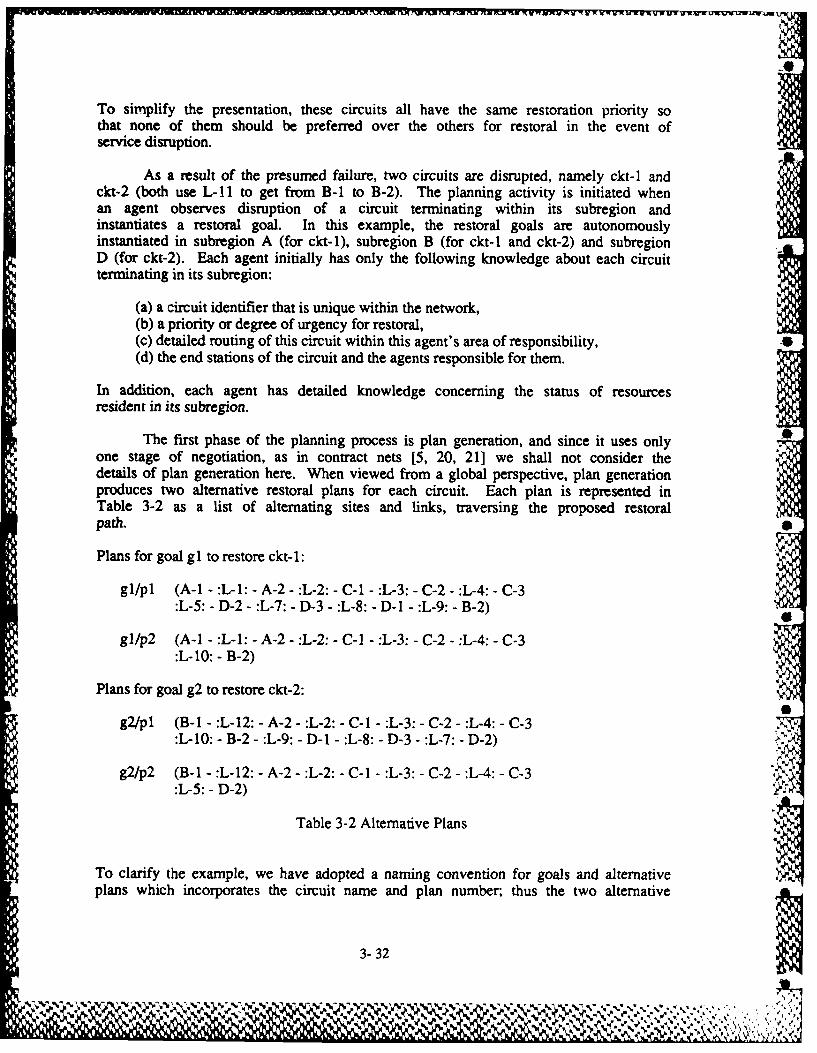
To simplify the presentation, these circuits all have the same restoration priority sothat none of them should be preferred over the others for restoral in the event ofservice disruption.
As a result of the presumed failure, two circuits are disrupted, namely ckt-1 andckt-2 (both use L-11 to get from B-1 to B-2). The planning activity is initiated whenan agent observes disruption of a circuit terminating within its subregion andinstantiates a restoral goal. In this example, the restoral goals are autonomouslyinstantiated in subregion A (for ckt-1), subregion B (for ckt-1 and ckt-2) and subregionD (for ckt-2). Each agent initially has only the following knowledge about each circuitterminating in its subregion:
(a) a circuit identifier that is unique within the network,(b) a priority or degree of urgency for restoral,(c) detailed routing of this circuit within this agent's area of responsibility,(d) the end stations of the circuit and the agents responsible for them.
In addition, each agent has detailed knowledge concerning the status of resourcesresident in its subregion.
The first phase of the planning process is plan generation, and since it uses only 0one stage of negotiation, as in contract nets [5, 20, 21] we shall not consider thedetails of plan generation here. When viewed from a global perspective, plan generationproduces two alternative restoral plans for each circuit. Each plan is represented inTable 3-2 as a list of alternating sites and links, traversing the proposed restoralpath.
Plans for goal gI to restore ckt-1:
gl/pl (A-1 - :L-1: - A-2 - :L-2: - C-1 - :L-3: - C-2 - :L-4: - C-3:L-5: - D-2 - :L-7: - D-3 - :L-8: - D-I - :L-9: - B-2)
gl/p2 (A-I - :L-1: - A-2 - :L-2: - C-1 - :L-3: - C-2 - :L-4: - C-3:L-10: -B-2)
Plans for goal g2 to restore ckt-2:
g2/pl (B-i - :L-12: - A-2 - :L-2: - C-I - :L-3: - C-2 - :L-4: - C-3:L-10: - B-2 - :L-9: - D-1 - :L-8: - D-3 - :L-7: - D-2)
g2/p2 (B-I - :L-12: - A-2 - :L-2: - C-1 - :L-3: - C-2 - :L-4: - C-3:L-5: - D-2)
Table 3-2 Alternative Plans
To clarify the example, we have adopted a naming convention for goals and alternative Vplans which incorporates the circuit name and plan number; thus the two alternative
3-32
Vp nmrtuh tw aea_ 3' ...V ' - " ' " -,-. ,-. , . .,. -, , - -, - ., - .- .- ,- ..., . - -,- .:.. ,, , , ,-, .-, ,%..

plans for restoring circuit ckt-I are designated gl/pl and gl/p2. It is essential toremember that these are global plans which have been generated in a distributed manner,and no single agent necessarily knows of all plans or any one complete plan.
As a result of plan generation, a node produces local alternative plan fragmentswhich may be used to satisfy global goals. Each global plan listed in Table 3-2 iscomposed of several fragments distributed over a subset of the agents. This isillustrated in Table 3-3.
Goal Plan Frag. Resources Used Cost -4
gl 1A L-l, L-2 9g2 7A L-2, L- 12 9
Agent A
gi 2B L-9 95B L-10 6
g2 8B L-9, L-10, L-12 9liB L-12 6
Agent B
gi 3C L-2, L-3, L-4, L-5 9 ,."
6C L-2, L-3, L-4, L-10 6g2 9C L-2, L-3, L-4, L-10 9 .''
12C L-2, L-3, L-4, L-5 6AgentC
gl 4D L-5, L-7, L-8, L-9 9g2 lOD L-7, L-8, L-9 9
13D L-5 6Agent D
Table 3-3 Local Knowledge About Plan Fragments
This table summarizes the knowledge each agent has about goals, alternative planfragments, and local resources. Plan fragments are numbered and each is identified by aletter indicating the responsible agent. Note that agents are not explicitly aware ofglobal alternative plans, but are only aware of local alternatives. For example, eventhough Agent A has resources needed by both gl/pl and gl/p2, the local plan fragment isthe same in both cases, and thus Agent A "sees" only one alternative plan for goal gl.
This example is considerably oversimplified in order to focus attention on thesignificant characteristics of this planning problem and to illustrate the cooperationstrategy which results from multistage negotiation. The communication network has beensimplified so that link capacity is the only resource, and thus there are no constraintsarising from local equipment configurations. The number of circuits and link capacitiesare also much smaller than is typical. Since only two top level goals exist, the
3-33
W,...-V -* % % 7

subgoal interactions are simple and can be recognized in only one step. In a morerealistic problem, subgoal interactions often involve multiple dependencies and mayrequire several steps of negotiation to detect and resolve.
The features of the planning problem which are important for the discussion ofmultistage negotiation in this paper are summarized below:
(a) Goals are autonomously generated at nodes in the system.
(b) The same system goal may be generated at more than one node, independently.
(c) Knowledge about local resource availability and potential goal interactions ateach node differs from that at other nodes.
(d) Goal satisfaction in general requires nonlocal resources.
(e) The planning problem being addressed is, in general, overconstrained. A choiceto satisfy some goals may preclude the satisfaction of others, so choiceheuristics are necessary.
S(f) Goals are prioritized, but this does not imply a total ordering with respect to
priority.
3.4.4 Model Of Problem Solving
The planning problem discussed in the previous section can be viewed in a broadercontext. In this section we characterize a problem solving model in which multistagenegotiation is useful. The search space for a problem of this kind can be consideredfrom two points of view: a task or goal centered perspective and a node centeredperspective. Each of these ways of viewing the search space provides a different set ofinsights with respect to problem solving. .v
When viewed from the perspective of the system goal, the global problem appears asan AND-OR tree progressing from the system goal (at the root), down through goals andplans, to local plan fragments distributed among the agents. A goal centered view ofour example problem is illustrated in Figure 3-7. Two goals have been instantiated,with four alternative plans and several local plan fragments. Of course, since this isa distributed environment, no single agent has a complete view of this tree. Observethat each agent is aware of both goals gl and g2, but agent D is only aware of one planfragment for gl, the one which is a component of gl/pl.
.. '
3-34
. .

AND
IvI.--
g. g2
OR OR
/p1 1/p1 .2/pi g2/p2
1A 3 lA 6C 7A 9 ~ 1 12C
III I II I I I -=---.
1268 58 F-8 8 O 16 3I '_ I I _, II I.. -- I I..,---------- , ---- ,-.....-
Figure 3-7 Global Search Space
An agent may not simply satisfy a local goal by choosing any plan fragment, butmust coordinate its choice so that it is compatible with those of other agents.Formulation of a plan as a conjunction of plan fragments induces a set of compatibilityconstraints on the local choices an agent makes in satisfaction of global goals. InFigure 3-7 we show the plan fragments interconnected by dashed lines. These dashed Alines indicate the local knowledge an agent has about which other agents are involved incompatibility constraint relations with its own plan fragments. Observe that an agentgenerally does not have complete knowledge about these compatibility sets. In ourapplication domain, these constraints involved shared resources between two agents.
From a node centered perspective, plan fragment selection is constrained by local ,
resource availability. An agent cannot choose to execute a set of alternative planfragments that require more local resources than are available. For example, agent B's -
local resources permit selection of any pair of its own plan fragments in satisfactionof gl and g2, whereas agents A, C, and D t. h can select only one plan fragment. The - .
resulting feasibility tree known to each ageit is shown in Figure 3-8. In this figure, .resource constraints associated with goals and plan fragments are enclosed by ovals andconnected to the appropriate objects with dashed line:. Restoral goals initiated in asubregion are designated with an S
3-35
% *
it~I

(A) (B)
() %.%
4D EDD
Figure 3-8 Local Feasibility Trees
3-36 I
%~

From each agent's perspective, the search is over a group of alternatives subjectto a set of local resource constraints and a set of compatibility constraints imposed byactions of other agents. Multistage negotiation provides a mechanism by which agentscoordinate their actions in selecting plans subject to both resource and compatibilityconstraints. As additional constraints are added to an agent's base of knowledge, itslocal feasibility tree is augmented to reflect what it has learned.
3.4.5 Multistage Negotiation
In this section, we describe the multistage negotiation protocol we have developedand give an example of its application in the distributed planning problem which hasbeen discussed. We first treat the protocol at a very high level, discussing thegeneral strategy. We then provide more detail as to phases of planning and the role ofnegotiation in each. The section is concluded with a detailed trace of negotiation andreasoning in each agent pertinent to our simple example.
3.4.5.1 High Level Protocol
Multistage negotiation provides a means by which an agent can acquire enoughknowledge to reason about the impact of local activity on nonlocal state and modify itsbehavior accordingly. When problem solving activity is initiated, agents first engagein a phase of plan generation. Each agent ascertains what alternatives for partial goalsatisfaction are locally possible and tenders contracts to appropriate agents forfurthering satisfaction of the goals needed to complete these plans. On completion ofthis phase, a space of alternative plans has been constructed which is'distributed amongthe agents, with each agent only having knowledge about its local plan fragments. Anagent then examines the goals it instantiated and makes a tentative commitment to thehighest rated feasible set of plan fragments relative to these goals. It subsequentlyissues requests for confirmation of that commitment to agents who hold the contracts forcompletion of these plan fragments.
Each agent may receive two kinds of communications from other agents: 1) requestsfor confirmation of other agents' tentative commitments, and 2) responses concerning theimpact of its own proposed commitments on others. Impact of local actions is reporteda,. confirmation that a tentative local choice is a good one or as negative information 4"
reflecting nonlocal resource conflict. The agent incorporates this new knowledge into VINits local feasibility tree. It rerates its own local goals using the new knowledge and 0|possibly retracts its tentative resource commitment in order to make a more informedchoice. This process of information exchange continues until a consistent set ofchoices can be confirmed.
Termination of the negotiation process can be done using system-wide criteria orit can be accomplished in a diffuse manner. If global termination criteria are desiredin an application, some form of token passing mechanism [7, 9, 25] can be used to detectthat the applicable termination criteria have been met. When synchronized globalternination is not required in an application, the negotiation can be terminated by an"irrevocable" commitment of resources. A node initiates plan execution in accordancewith its negotiated tentative commitment at some time after it has no pending activities 0
3-37

and no work to do for other agents.
3.4.5.2 Mechanics of Negotiation
When a node begins its planning activity, it has knowledge of a set of top levelgoals which have been locally instantiated. A space of plans to satisfy each of thesegoals is formulated during plan generation without regard for any subgoal interactionproblems. After plan generation, each node is aware of two kinds of goals: primarygoals (or p-goals) and secondary goals (or s-goals). In our application, p-goals are ---
those instantiated locally by an agent in response to an observed outage of a circuitfor which the agent has primary responsibility (because the circuit terminates in theagent's subregion). These are of enhanced importance to this agent because they relateto system goals which must be satisfied by this particular agent if they are to besatisfied at all. An agent's s-goals are those which have been instantiated as a resultof a contract with some other agent. An agent regards each of its s-goals as a possiblealternative to be utilized in satisfaction of some other agent's p-goal.
A plan commitment phase involving multistage negotiation is initiated next. Asthis phase begins, each node has knowledge about all of the p-goals and s-goals it hasinstantiated. Relative to each of its goals, it knows a number of alternatives for goal 0satisfiction. An alternative is comprised of a local plan fragment, points ofinteraction with other agents (relative to that plan fragment), and a measure of thecost of the alternative (to be used in making heuristic decisions). Negotiation leadingto a commitment proceeds along the following lines.
1. Each node examines its own p-goals, making a tentative commitment to the highestrated set of locally feasible plan fragments for p-goals (s-goals are notconsidered at this point because some other agent has corresponding p-goals).
2. Each node requests that other agents attempt to confirm a plan choice consistentwith its commitment. Note that an agent need only communicate with agents whocan provide input relevant to this tentative commitment.
3. A node examines its incoming message queue for communications from other nodes.Requests for confirmation of other agents' tentative commitments are handled byadding the relevant s-goals to a set of active goals. Responses to this agent'sown requests are incorporated in the local feasibility tree and used asadditional knowledge in making revisions to its tentative commitment.
4. The set of active goals consists of all the local p-goals together with thoses-goals that have been added (in step 3). The agent rates the alternativesassociated with active goals based on their cost, any confirming evidence thatthe alternative is a good choice, any negative evidence in the form of nonlocalconflict information, and the importance of the goal (p-goal, s-goal, etc. ). A %J, b-%
revised tentative commitment is made to a highest rated set of locally P
consistent alternatives for active goals. In general, this may involvedecisions to add plan fragments to the tentative commitment and to delete planfragments from the old tentative commitment. Messages reflecting any changes in
3- 38
C. I'

the tentative commitment and perceived conflicts with that commitment aretransmitted to the appropriate agents.
5. The incoming message queue is examined again aind activity proceeds as d.cribed Sabove (from step 3). The process of aggregating knowledge about nonlocal '
conflicts continues until a node is aware of all conflicts in which its planfragments are a contributing factor.
Two issues need clarification at this point. One deals with the question oftermination and the other is concerned with the quality of the result obtained throughnegotiation (relative to optimality).
Negotiation in this framework continues as long as there are any pendingactivities in an agent. The only way a situation leading to nontermination could ariseinvolves an agent's making a tentative commitment and subsequently entering a cycle ofretracting and remaking that commitment indefinitely. It is not reasonable to expectthat an agent should never retract a tentative commitment. It is also not reasonable toexpect that an agent would never decide, based on new knowledge, to recommit to analternative it had previously rejected. An agent's local reasoning must be able todetect when it is making a tentative commitment it has previously made with no newknowledge. Negotiation activity in an agent terminates either when it has no pendingactivity and no incoming communications or if an attempt is made to return to a previouscommitment with no new knowledge from other agents. Endless loops of commitment anddecommitment are prevented through this mechanism.
The other issue of importance at this point is related to the quality of theresult obtained through negotiation. In the initial negotiation stage, each agentexamines only its p-goals and makes a tentative commitment to a locally feasible set ofplan fragments in partial satisfaction of those goals. Since each agent is consideringjust its p-goals at this stage, the only reason for an agent's electing not to attemptsatisfaction of some top level goal is that two or more of these goals are locally knownto be infeasible. (This corresponds to an overconstrained problem.)
In subsequent stages of negotiation, both p-goals and relevant s-goals areconsidered in making new tentative commitments. The reasoning strategy employed at eachagent will only decide to forego commitment to one of its p-goals if it has learned thatsatisfaction of this p-goal precludes the satisfaction of one or more other p-goalselsewhere in the system. If the system goal of satisfying all of the p-goals ,rinstantiated by agents in the network is feasible, no agent will ever be forced toforego satisfaction of one of its p-goals (because no agent will ever learn that itsp-goal precludes others), and a desired solution will be found. If, on the other hand,the problem is overconstrained, some set of p-goals cannot be satisfied and the systemtries to satisfy as many as it can. While there is no guarantee of optimality, theheuristics employed should ensure that a reasonably thorough search is made.
To make these concepts concrete, multistage negotiation is applied to thesimplified planning problem discussed in the previous sections. 0
3-39
" ".: ;. :

U
3.4.5.3 Example
We return to our example of nlanning activity, assuming that each agent has theknowledge depicted in the appropriate part of Figure 3-8. A summary of the transactionsthat occur during negotiation to achieve plan selection is shown in Table 3-4. Thistable is segmented by agent and by "time slice" to convey a sense of progress in problemsolving through negotiation. The notational conventions are relatively simple.Tentative commitment to a locally known activity and the associated communication issuedto an appropriate agent is denoted in the form (plan fragment name; message -> agent).Exchange of conflict information is indicated in the form (conflict; type of conflict ->agent). To make the trace easier to follow, each received message is noted in the form(source agent -> message).
As is evident in Table 3-4 negotiation begins with tentative commitments toalternatives in agents A, B, and D. Though the problem is overconstrained (it is notpossible to restore both ckt-1 and ckt-2), no agent is yet aware of that fact. Inresponse to the initial tentative commitments, there is activity in agents A and C.Agent A knows that it cannot act to satisfy both gl and g2, but it does not know if thisprecludes satisfaction of g2 (since g2 is an s-goal, there might exist another globalplan not requiring any action by A). Since A recognizes the need to attemptsatisfaction of its own p-goal first, agent A informs agent B there is a conflictbetween what B requested and satisfaction of one of A's p-goals. Thus A has given B theknowledge that the plan fragment B selected would force A to forego one of its p-goals.
Agent C has now received three communications requesting that plan fragments beextended. It observes that it can effect a plan completion for gl, satisfying both therequest from A and the request from B. It also observes that it cannot satisfy both gland g2 with use of its locally known plan fragments due to local resource constraints.Since it has the opportunity to complete a plan for ckt-1 and not for ckt-2, it electsto tentatively commit its resources to plan fragment 6C. Messages reflecting this
commitment are formulated and transmitted to A and B, while a message indicating theconflict in C is sent to D.
As a result of this second round of communications, activity in subregions B and Dis concerned with exploring the remaining alternatives they have for restoral of ckt-2.An acceptable plan for ckt- 1 is already reflected in tentative commitments. Agent Belects to try plan fragment 8B and agent D elects to try 10D. Agent B learns that anattempt to satisfy g2 via 8B also fails in A, so it now knows that the problem is ,.overconstrained. Based on the fact that a way of satisfying g l has already beenlocated, B elects to forego satisfaction of g2 and advises D that it should also give upon g2. Negotiation terminates with tentative commitments reflecting a plan choice forgl.
3-40
. ... . . . , , .. - ,) " ,' - -,, " ,-, . - '- ", " ", .- . N.

Agent A Agent B Agent C Agent D
IA; OK? -> C IliB; OK? -> A 13D; OK?->C 5B; OK? ->C
B -> OK? IB A ->OK? IAB -> OK? 5B
conflict; D ->OK? 13D(liB AND not p-goal g1)-> B match 6C with
IA and 5B
IA is OK ->A5B is OK -> B S
conflict;(13D AND not gl via C)-> D
C -> IA is OK A-> C->(I IB AND not p-goal gl) (13D AND not g I
via C)C -> 5B is OK
8B; OK? -> A 10D; OK? -> B
B ->OK^ 8B D -> OK? 10D
conflict; 8B; OK? -> C(8B AND not p-goal gI) %-> B
A-> B ->OK? 8B ', , ;(8B AND not p-goal gI)
B knows gI and g2 conflict;not both possible (8B AND not gl via C)
->B
(not both gl and g2)-> D
C-> B->(8B AND not gI via C) (not both gI and g2)
%W %I
Table 3-4 Summary of Transactions During Negotiation 1,0 .
3-41

In concluding this section we summarize, by "time slice", changes to the localfeasibility trees that take place during the negotiation illustrated in Table 3-4.
Slice 1: .0No changes
Slice 2:No changes in constraints by A6C is tentatively committed to a complete plan by C
Slice 3:1A is marked as tentatively satisfying gl by A5B is marked as tentatively satisfying gl by BAgent B adds the constraint (not gI) to 1 BAgent D adds the constraint (not gl via C) to 13D (Note that in this example, thenew constraint on 13D is, in fact, redundant. In other examples, with a morecomplex set of goals, new constraints propagated in this way often provideadditional information.)
Slice 4:No changes
Slice 5:Agent B adds the constraint (not gl) to 8BAgent B propagates the constraint (nci gl) on 8B and 1 1B to their parent, g2.Agent B now knows the problem is overconstrained.
Slice 6:Agent D modifies the constraint (not gl) on goal g2* to (not gl*).Agent D now knows the problem is overconstrained.
This example illustrates ways in which knowledge is integrated into the localfeasibility tree as it is acquired through negotiation. It shows how knowledgeaggregated at the level of plan segments can be propagated in drawing inferencesconcerning interactions at the goal level. It also shows how the network of agents canbecome aware that it has an overconstrained problem.
3.4.6 Concluding Remarks
We have developed a new paradigm for cooperation in distributed problem solvingsystems. This paradigm incorporates features found in two cooperation strategiestreated in the literature: the contract net protocol [5, 20, 21] and the FA/C paradigm[14]. It has been devised to permit an agent in a distributed problem solving system toacquire enough knowledge to reason about the impact of local activity on nonlocal stateand to modify its behavior accordingly.
3-42Pe
11
Three characteristics of distributed planning problems motivate development of amore general cooperation paradigm. First, subgoal interaction problems that arise inthe context of a distributed planning system in which agents do not have a global vieware very difficult to detect and even more difficult to handle in a reasonable way. .Second, many application domains embody planning problems that are overconstrained.When these planning problems are addressed by a network of planning agents, it isessential that the system be able to determine whether or not the problem isoverconstrained. Third, when the planning problem is overconstrained, it is necessaryfor the agents involved to arrive at an agreement as to a set of goals whosesatisfaction is regarded as an acceptable solution to the problem at hand. None ofthese issues can be resolved in the context of the previously proposed cooperationparadigms without the exchange of sufficient knowledge as to permit each agent toconstruct a global view.
Another factor motivating formulation of a more general cooperation paradigm is Sthe observation that many application domains have characteristics that distinguish themfrom other multi-agent planning problems which have been investigated. The strategiessuggested by Lansky [13] and Georgoff [11] dealing with planning for a multiple agentdomain by a centralized planner are not applicable in situations where there is nocentral planner. In addition, the agents in our networks are not motivated purely byself interest. They are interested in cooperating to achieve some goals pertinent tosystem performance. For this reason, the metaphor proposed by Genesereth and others[10] does not represent the domain characteristics. It should be noted, however, thatour metaphor can be adapted for use in networks of agents which are selfish (as long asthey do not lie a great deal).
The mechanisms presented in this paper are related to the techniques that havebeen utilized in conventional planning systems. Each agent in our system builds a datastructure analogous to the Table of Multiple Effects used by NOAH [ 18] and NONLIN [24] .in detecting subgoal interactions. This structure is incrementally built usingknowledge gleaned through negotiation. In detecting and resolving conflicts, a form ofcriticism analogous to that performed by NOAH's Resolve Conflicts critic is employed. ,Criticism is necessary in our distributed problem solving systems for the same reason itwas needed in NOAH - decisions are made initially based on local criteria, whereasnonlocal conditions affect the viability of those decisions. Unlike NOAH (and likeNONLIN), alternatives are not discarded after they have been rejected. Backtracking inthe form of revised tentative commitment is a feature of the protocol. a
In many planning problems, the constraints arising from resource availability arevery important in determining a satisfactory solution to the planning problem. We havefound that resource constraints play a crucial role in our system as well. The abilityto reason about resources is critical in determining adequate solutions. This wasrecognized in the design of SIPE [261. Since we have no central planner, the mechanismsfor reasoning about resources are somewhat different from those employed in SIPE, but .6resources as a factor in problem solving are just as important to multistage negotiationas they were in SIPE.
S
3-43
- " w ' ' --. "' ,, .' . .' . , ' -. . * *".* - - . . - 1, , , 4 . ".',.

BIBLIOGRAPHY
[1] D. G. Bobrow, "Qualitative Reasoning About Physical Systems: An Introduction,"Artificial Intelligence, vol. 24, December 1984.
[21 H. Brown, C. Tonge, and G. Foyster, "Palladio: An Exploratory Environment forCircuit Design," IEEE Computer, December 1983, pp. 41-56.
[3] S. E. Conry, R. A. Meyer, and V. R. Lesser, "Multistage Negotiation in DistributedPlanning", University of Massachusetts, Amherst Massachusetts 01003, COINSTechnical Report 86-67 December 1986.
[4] S. E. Conry, R. A. Meyer, and J. E. Searleman, "A Shared Knowledge Base forIndependent Problem Solving Agents," Proceedings of the Expert Systems inGovernment Symposium, IEEE Computer Society, McLean, Virginia, October 1985.
[5] R. Davis and R. G. Smith, "Negotiation as a Metaphor for Distributed ProblemSolving," Artificial Intelligence, vol. 20, no. 1, January 1983, pp. 63-109.
[6] B. Delagi, "Care User's Manual," Knowledge Systems Laboratory, Department ofComputer Science, Stanford University, 1986.
[7] E. W. Dijkstra and C. S. Scholten, "Termination Detection for DiffusingComputations," Information Processing Letters, vol. 11, no. 1, August 1980, pp.1-4.
[81 R. Fikes and T. Kehler, "The Role of Frame Based Representation in Reasoning,"Communications of the ACM, vol. 28, no. 9, September 1985, pp. 904-920.
[9] N.Francez,"DistributedTermination",ACMTransactionsonProgrammingLanguagesand Systems, vol. 2, no. 1, January 1980, pp. 42-55. 0
[10] M. R. Genesereth, M. L. Ginsberg, and J. S. Rosenschein, "Cooperation WithoutCommunication," Proceedings of the National Conference on Artificial Intelligence(AAAI-86), August 1986, pp. 51-57.
[11I M. Georgeoff, "Communication and Interaction in Multi-Agent Planning," Proceedings •of the National Conference on Artificial Intelligence (AAAI-84), August 1984, pp.125-129.
[12] C. Hewitt, "Concurrency in Intelligent Systems." Al Expert (Premier), 1986, pp.44-50.
[131 A. L. Lansky, "Behavioral Specification and Planning for Multiagent Domains,"Technical Note 360, SRI International, Menlo Park, CA, November 1985.
[141 V. R. Lesser and D. D. Corkill, "Functionally Accurate, Cooperative DistributedSystems," IEEE Transactions on Systems, Man, and Cybernetics, vol. SMC- 11, no. 1,
3-44

January 1981, pp. 81-96.
[15] D. J. MacIntosh and S. E. Conry, "SIMULACT, A Generic Tool for SimulatingDistributed Systems, Tools for the Simulation Profession, The Society for ComputerSimulation. San Diego, CA (Orlando, Florida, April 1987), pp. 18-23.
[16] M. C. Maguire, "A Review of Human Factors Guidelines and Techniques for the Designof Graphical Human-Computer Interfaces," Computers and Graphics, vol. 9, no. 3,1985, pp. 221-235.
[17] J. G. March and H. A. Simon, Organizations, Wiley, 1958.
[18] E. D. Sacerdoti, A Structure for Plans and Behavior, Elsevier - North Holland, NewYork, 1977.
[19] E.Schoen,"TheCAOSSystem,"KnowledgeSystemsLaboratory,DepartmentofComputerScience, Stanford University, Report no. KSL-86-22, March 1986.
[20] R. G. Smith, "The Contract Net Protocol: High Level Communication and Control in aDistributed Problem Solver," IEEE Transactions on Systems, Man, and Cybernetics,vol. SMC-1O, no. 12, December 1980.
[21] R. G. Smith and R. Davis, "Frameworks for Cooperation in Distributed ProblemSolving,"IEEE Transactions on Systems, Man, and Cybernetics, vol. SMC-11, no. 1,January 1981, pp. 61-70.
[22] G. Steele, Common LISP, Digital Press, Burlington, MA., 1984.
[23] A. S. Tanenbaum, Computer Networks, Prentice-Hall, 1981.
[24] A. Tate, "Project Planning using a Hierarchic Non-Linear Planner," Research ReportNo. 25, Department of Artificial Intelligence, University of Edinburgh, August1976.
[25] S. Vinter, K. Ramamritham, and D. Stemple, "Recoverable Communicating Actions inGutenberg," Proceedings of the International Conference on Distributed ComputingSystems, May 1986.
[261 D. E. Wilkins, Domain-Independent Planning: Representation and Plan Generation,"Artificial Intelligence, vol. 22, pp. 269-301.
3-45
101~
Lam7 t

Z--
'44'
.44v

I i
Comm
A-wEDI~