Embed Size (px)
Citation preview
Instruments and implants approved by the AO Foundation.This publication is not intended for distribution in the USA.
SURGICAL TECHNIQUE
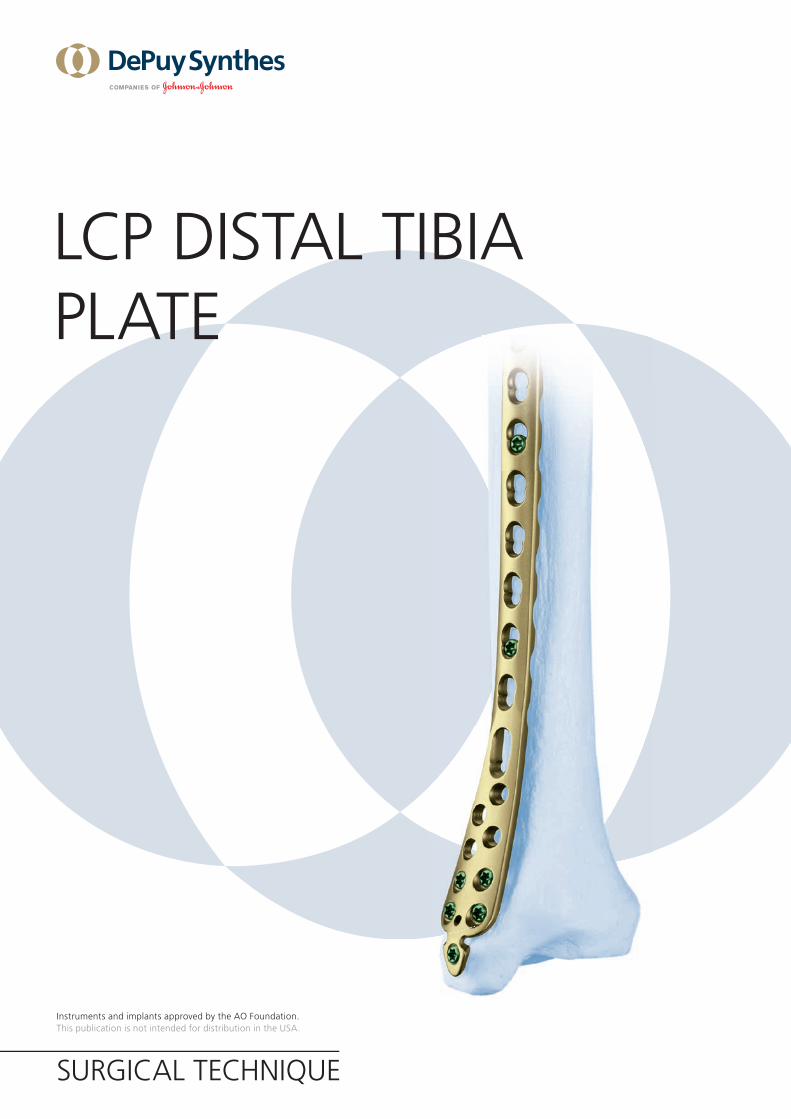
LCP DISTAL TIBIA PLATE

Image intensifier control
This description alone does not provide sufficient background for direct use of DePuy Synthes products. Instruction by a surgeon experienced in handling these products is highly recommended.
Processing, Reprocessing, Care and MaintenanceFor general guidelines, function control and dismantling of multi-part instruments, as well as processing guidelines for implants, please contact your local sales representative or refer to:http://emea.depuysynthes.com/hcp/reprocessing-care-maintenanceFor general information about reprocessing, care and maintenance of Synthes reusable devices, instrument trays and cases, as well as processing of Synthes non-sterile implants, please consult the Important Information leaflet (SE_023827) or refer to: http://emea.depuysynthes.com/hcp/reprocessing-care-maintenance
LCP Distal Tibia Plate Surgical Technique DePuy Synthes 1
TABLE OF CONTENTS
INTRODUCTION LCP Distal Tibia Plate 2
AO Principles 4
Indications 5
SURGICAL TECHNIQUE Reduce Articular Surface 6
Insert Plate 7
Position Plate and Fix Provisionally 8
Insert Screws 9
Implant removal 15
PRODUCT INFORMATION Implants and Instruments 16
MRI INFORMATION 25
1 DePuy Synthes LCP Distal Tibia Plate Surgical Technique
LCP DISTAL TIBIA PLATE
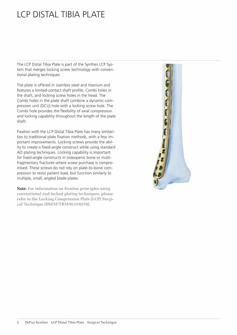
The LCP Distal Tibia Plate is part of the Synthes LCP Sys-tem that merges locking screw technology with conven-tional plating techniques.
The plate is offered in stainless steel and titanium and features a limited-contact shaft profi le, Combi holes in the shaft, and locking screw holes in the head. The Combi holes in the plate shaft combine a dynamic com-pression unit (DCU) hole with a locking screw hole. The Combi hole provides the fl exibility of axial compression and locking capability throughout the length of the plate shaft.
Fixation with the LCP Distal Tibia Plate has many similari-ties to traditional plate fi xation methods, with a few im-portant improvements. Locking screws provide the abil-ity to create a fi xed-angle construct while using standard AO plating techniques. Locking capability is important for fi xed-angle constructs in osteopenic bone or multi-fragmentary fractures where screw purchase is compro-mised. These screws do not rely on plate-to-bone com-pression to resist patient load, but function similarly to multiple, small, angled blade plates.
Note: For information on fi xation principles using conventional and locked plating techniques, please refer to the Locking Compression Plate (LCP) Surgi-cal Technique (DSEM/TRM/0115/0278).
LCP Distal Tibia Plate Surgical Technique DePuy Synthes 1
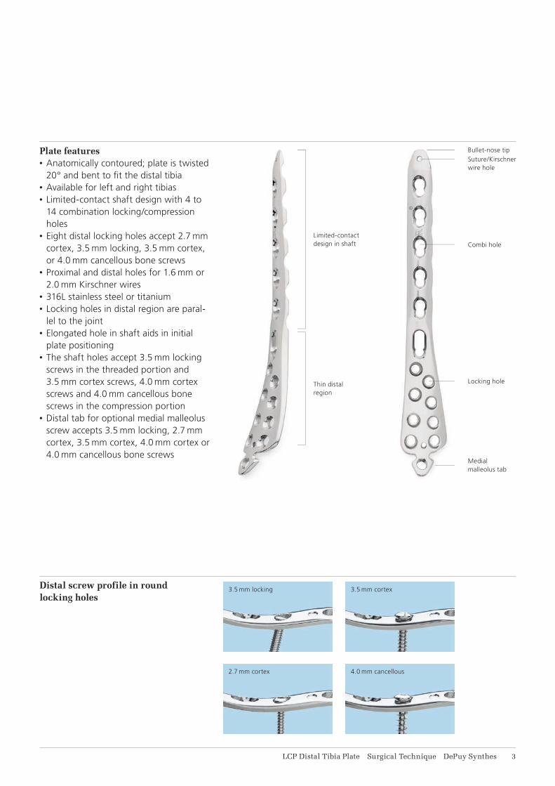
Plate features• Anatomically contoured; plate is twisted
20° and bent to fi t the distal tibia• Available for left and right tibias• Limited-contact shaft design with 4 to
14 combination locking/compression holes
• Eight distal locking holes accept 2.7 mm cortex, 3.5 mm locking, 3.5 mm cortex, or 4.0 mm cancellous bone screws
• Proximal and distal holes for 1.6 mm or 2.0 mm Kirschner wires
• 316L stainless steel or titanium• Locking holes in distal region are paral-
lel to the joint• Elongated hole in shaft aids in initial
plate positioning• The shaft holes accept 3.5 mm locking
screws in the threaded portion and 3.5 mm cortex screws, 4.0 mm cortex screws and 4.0 mm cancellous bone screws in the compression portion
• Distal tab for optional medial malleolus screw accepts 3.5 mm locking, 2.7 mm cortex, 3.5 mm cortex, 4.0 mm cortex or 4.0 mm cancellous bone screws
Distal screw profile in round locking holes
Limited-contact design in shaft
Bullet-nose tipSuture/Kirschner wire hole
Combi hole
Locking hole
Medial malleolus tab
3.5 mm locking
2.7 mm cortex
3.5 mm cortex
4.0 mm cancellous
Thin distal region
4 DePuy Synthes LCP Distal Tibia Plate Surgical Technique
AO PRINCIPLES
1
4
2
3
4_Priciples_03.pdf 1 05.07.12 12:08
4 DePuy Synthes Expert Lateral Femoral Nail Surgical Technique
AO PRINCIPLES
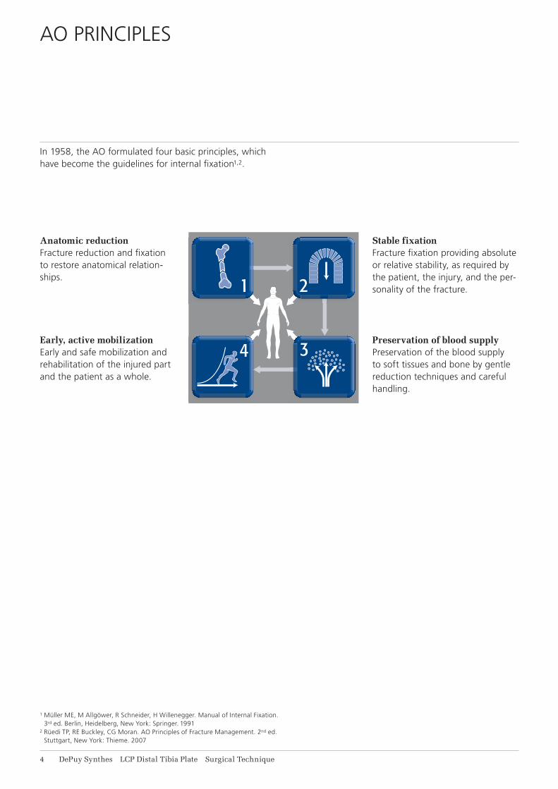
In 1958, the AO formulated four basic principles, which have become the guidelines for internal fixation1, 2.
1 Müller ME, M Allgöwer, R Schneider, H Willenegger. Manual of Internal Fixation. 3rd ed. Berlin Heidelberg New York: Springer. 1991.
2 Rüedi TP, RE Buckley, CG Moran. AO Principles of Fracture Management. 2nd ed. Stuttgart, New York: Thieme. 2007.
Anatomic reductionFracture reduction and fixation to restore anatomical relationships.
Early, active mobilizationEarly and safe mobilization and rehabilitation of the injured part and the patient as a whole.
Stable fixationFracture fixation providing abso-lute or relative stability, as required by the patient, the injury, and the personality of the fracture.
Preservation of blood supplyPreservation of the blood supply to soft tissues and bone by gentle reduction techniques and careful handling.
Stable fixationFracture fixation providing absolute or relative stability, as required by the patient, the injury, and the per-sonality of the fracture.
Anatomic reductionFracture reduction and fixation to restore anatomical relation-ships.
Early, active mobilizationEarly and safe mobilization and rehabilitation of the injured part and the patient as a whole.
Preservation of blood supplyPreservation of the blood supply to soft tissues and bone by gentle reduction techniques and careful handling.
In 1958, the AO formulated four basic principles, which have become the guidelines for internal fixation1,2.
1 Müller ME, M Allgöwer, R Schneider, H Willenegger. Manual of Internal Fixation. 3rd ed. Berlin, Heidelberg, New York: Springer. 1991
2 Rüedi TP, RE Buckley, CG Moran. AO Principles of Fracture Management. 2nd ed. Stuttgart, New York: Thieme. 2007

LCP Distal Tibia Plate Surgical Technique DePuy Synthes 5
INDICATIONS
• Extra-articular and simple intra-articular distal tibial fractures
• Distal tibial fractures, percutaneous or reducible by limited arthrotomy
• Distal tibial fracture extending into the diaphyseal area
6 DePuy Synthes LCP Distal Tibia Plate Surgical Technique
REDUCE ARTICULAR SURFACE
Reduce articular surface
Instruments
292.160 or Kirschner Wire B 1.6 mm with trocar tip,492.160 length 150 mm, Stainless Steel or
Titanium Alloy (TAV)
292.200 or Kirschner Wire B 2.0 mm with trocar tip,492.200 length 150 mm, Stainless Steel or
Titanium Alloy (TAV)
Note: Prior to reduction, application of an external fixator or large distractor may facilitate visualization and reduction of the joint. Reduce the fracture fragments and confirm reduction using image intensification. Reduction may be stabilized using the following methods:• Independent Kirschner wires• Kirschner wires through the plate• Independent lag screws• Lag screws through the plate• Locking screws through the plate
Locking screws do not provide interfragment compres-sion; therefore, any desired compression must be achieved with standard lag screws. The articular fractures must be reduced and compressed before fixation of the LCP Distal Tibia Plate with locking screws.
2.7 mm or 3.5 mm cortex screws may also be used as lag screws through the plate by overdrilling the near frag-ment.
Note: To verify that independent lag screws will not interfere with plate placement, evaluate placement with AP and lateral fluoroscopic image.
LCP Distal Tibia Plate Surgical Technique DePuy Synthes 7
INSERT PLATE
Bend or cut off the distal tab (optional)
Instrument
391.963 Universal Bending Pliers, length 165 mm
391.931 Cutting Pliers for Plates, length 230 mm
329.916 Bending Pin for LCP Plates 3.5, with thread
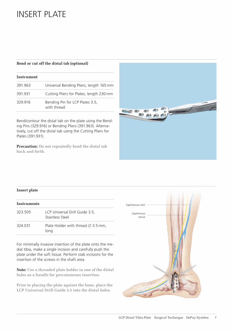
Bend/contour the distal tab on the plate using the Bend-ing Pins (329.916) or Bending Pliers (391.963). Alterna-tively, cut off the distal tab using the Cutting Pliers for Plates (391.931).
Precaution: Do not repeatedly bend the distal tab back and forth.
Insert plate
Instruments
323.505 LCP Universal Drill Guide 3.5, Stainless Steel
324.031 Plate Holder with thread B 3.5 mm, long
For minimally invasive insertion of the plate onto the me-dial tibia, make a single incision and carefully push the plate under the soft tissue. Perform stab incisions for the insertion of the screws in the shaft area.
Note: Use a threaded plate holder in one of the distal holes as a handle for percutaneous insertion. Prior to placing the plate against the bone, place the LCP Universal Drill Guide 3.5 into the distal holes.
Saphenous vein
Saphenous nerve
8 DePuy Synthes LCP Distal Tibia Plate Surgical Technique
POSITION PLATE AND FIX PROVISIONALLY
Position plate and fix provisionally
Instrument
292.160 or Kirschner Wire B 1.6 mm with trocar tip,492.160 length 150 mm, Stainless Steel or
Titanium Alloy (TAV)
292.200 or Kirschner Wire B 2.0 mm with trocar tip,492.200 length 150 mm, Stainless Steel or
Titanium Alloy (TAV)
Position the plate onto the bone and fix provisionally with Kirschner wires. Before inserting the first locking screw, ensure that the plate shows good provisional fixation, otherwise the plate may rotate during screw locking and cause soft tissue damage.
Locking screw insertion may prevent any further reduc-tion.
LCP Distal Tibia Plate Surgical Technique DePuy Synthes 9
INSERT SCREWS
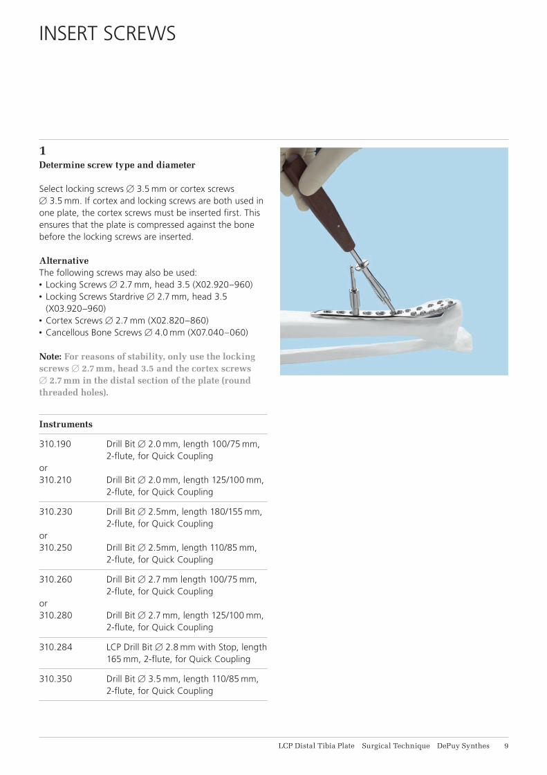
1Determine screw type and diameter
Select locking screws B 3.5 mm or cortex screws B 3.5 mm. If cortex and locking screws are both used in one plate, the cortex screws must be inserted first. This ensures that the plate is compressed against the bone before the locking screws are inserted.
Alternative The following screws may also be used: • Locking Screws B 2.7 mm, head 3.5 (X02.920–960) • Locking Screws Stardrive B 2.7 mm, head 3.5
(X03.920–960) • Cortex Screws B 2.7 mm (X02.820–860) • Cancellous Bone Screws B 4.0 mm (X07.040–060)
Note: For reasons of stability, only use the locking screws B 2.7 mm, head 3.5 and the cortex screws B 2.7 mm in the distal section of the plate (round threaded holes).
Instruments
310.190 Drill Bit B 2.0 mm, length 100/75 mm, 2-flute, for Quick Coupling
or310.210 Drill Bit B 2.0 mm, length 125/100 mm,
2-flute, for Quick Coupling
310.230 Drill Bit B 2.5mm, length 180/155 mm, 2-flute, for Quick Coupling
or310.250 Drill Bit B 2.5mm, length 110/85 mm,
2-flute, for Quick Coupling
310.260 Drill Bit B 2.7 mm length 100/75 mm, 2-flute, for Quick Coupling
or310.280 Drill Bit B 2.7 mm, length 125/100 mm,
2-flute, for Quick Coupling
310.284 LCP Drill Bit B 2.8 mm with Stop, length 165 mm, 2-flute, for Quick Coupling
310.350 Drill Bit B 3.5 mm, length 110/85 mm, 2-flute, for Quick Coupling
11 DePuy Synthes LCP Distal Tibia Plate Surgical Technique
Insert Screws
312.922 LCP Drill Sleeve 2.7, for Drill Bits B 2.0 mm
323.027 LCP Drill Sleeve 3.5, for Drill Bits B 2.8 mm
323.260 Universal Drill Guide 2.7
323.360 Universal Drill Guide 3.5
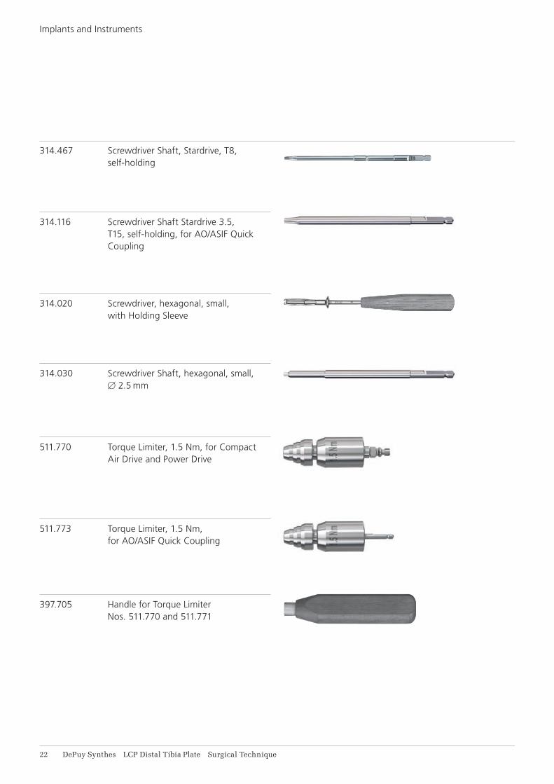
313.302 Screwdriver Stardrive, T8, cylindrical, with Groove, shaft B 3.5 mm
314.041 Screwdriver Stardrive 3.5, T15, with Groove, length 200 mm
311.431 Handle with Quick Coupling
314.467 Screwdriver Shaft, Stardrive, T8, self-holding
314.116 Screwdriver Shaft Stardrive 3.5, T15, self-holding, for AO/ASIF Quick Coupling
314.020 Screwdriver, hexagonal, small, with Holding Sleeve
314.030 Screwdriver Shaft, hexagonal, small, B 2.5 mm
319.010 Depth Gauge for Screws B 2.7 to 4.0 mm, measuring range up to 60 mm
511.770 Torque Limiter, 1.5 Nm, for Compact Air Drive and Power Drive
or511.773 Torque Limiter, 1.5 Nm,
for AO/ASIF Quick Coupling
397.705 Handle for Torque Limiter Nos. 511.770 and 511.771
Power tool unit:
511.701 Compact Air Drive II
530.100 Power Drive
LCP Distal Tibia Plate Surgical Technique DePuy Synthes 11
2Drill screw holes
a. Standard screwsWhen drilling for standard screws with the Universal Drill Guide (323.260 or 323.360) and the matching drill bit, drill the screw hole neutrally (1) or off-centre (2).
Use the following drill bits: • For cortex screw B 3.5 mm and cancellous bone screw
B 4.0 mm (alternative): Drill Bit B 2.5 mm (310.230 or 310.250)
• For cortex screw B 2.7 mm (alternative): Drill Bit B 2.0 mm (310.190 or 310.210)
Note: When using a cortex screw B 3.5 mm or B 2.7 mm (alternative) as a lag screw, drill the cor-tex of the nearby fragment with a larger bit (Drill Bit B 3.5 mm [310.350] for cortex screw B 3.5 mm and Drill Bit B 2.7 mm [310.260] for cortex screw B 2.7 mm).
b. Locking screwsWhen drilling for locking screws, screw the LCP Drill Sleeve for locking screws B 3.5 mm (323.027) or B 2.7 mm (312.922) into the desired threaded hole until the sleeve is fully gripped by the thread.
The LCP drill sleeve ensures that the locking screw is locked in the plate in the correct alignment. Angular sta-bility is reduced if the locking screws are inserted obliquely.
Note: Do not bend the plate with the drill sleeve as this may damage the sleeve. Drill the screw hole with a suitable drill bit.
Use the following drill bits: • For locking screw B 3.5 mm: Drill Bit B 2.8 mm
(310.284) • For locking screw B 2.7 mm: Drill Bit B 2.0 mm
(310.190 or 310.210)
11 DePuy Synthes LCP Distal Tibia Plate Surgical Technique
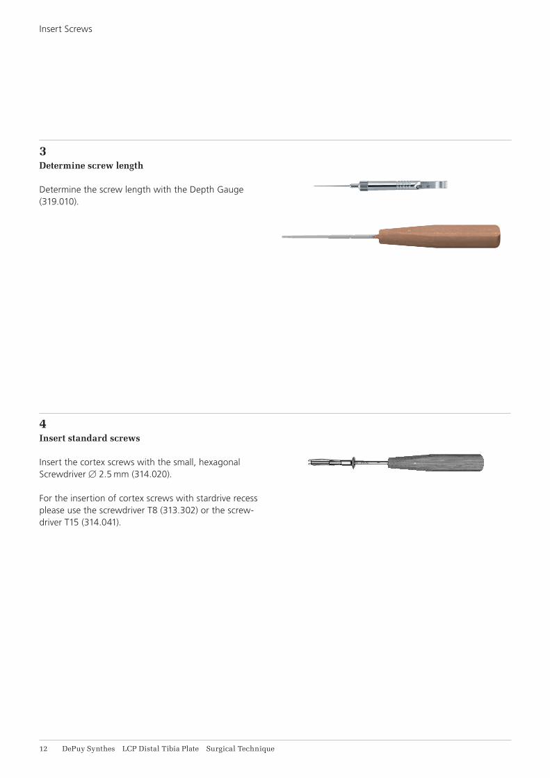
3Determine screw length
Determine the screw length with the Depth Gauge (319.010).
4Insert standard screws
Insert the cortex screws with the small, hexagonal Screwdriver B 2.5 mm (314.020).
For the insertion of cortex screws with stardrive recess please use the screwdriver T8 (313.302) or the screw-driver T15 (314.041).
Insert Screws
LCP Distal Tibia Plate Surgical Technique DePuy Synthes 11
5Insert locking screws
a. Mechanically To insert the locking screws mechanically, attach the Torque Limiter 1.5 Nm (511.770) to the power tool unit (Compact Air Drive II 511.701 or Power Drive 530.100). Insert the Hexagonal Screwdriver Shaft (314.030) or the Screw driver Shaft Stardrive 3.5 (314.116) into the torque limiter. Pick up the locking screw and insert it into the plate hole. To insert the screw, start the power tool unit slowly, increase the speed and then reduce again before the screw is fully tightened. The torque is automatically limited and a clearly audible click signifies that the maxi-mum torque has been reached. Stop the power tool unit immediately and discon nect from the screw.
Warning: Never insert locking screws under power unless using a torque limiting attachment.
Note: Do not lock the screw at full speed as this risks damaging the hexagonal or Stardrive recess, making implant removal more difficult.
Note: With porous bone there is a risk that the lock-ing screw will fail to follow the drilled hole, result-ing in a slightly oblique hole during mechanical insertion of the screw with subsequent partial loss of angular stability. In case of porous bone, manual locking (with the handle for torque limiter) of the screws is recommended to ensure better guidance through the drilled hole.
b. Manually To insert the locking screws manually, attach the torque limiter 1.5 Nm to the Handle for Torque Limiter (397.705) and insert the screwdriver shaft.
Lock the locking screws in the plate.
14 DePuy Synthes LCP Distal Tibia Plate Surgical Technique
If using a locking screw as the first screw, be sure the plate is held securely to the bone to prevent plate rota-tion as the screw is locked to the plate.
Note: The locking screw is not a lag screw. Use stan-dard screws when requiring a precise anatomical reduction (e.g. joint surfaces) or interfragmentary compression. Before inserting the first locking screw, perform anatomical reduction and fix the fracture with lag screws, if necessary. After the in-sertion of locking screws, an anatomical reduction will no longer be possible without loosening the locking screws.
Insert Screws
LCP Distal Tibia Plate Surgical Technique DePuy Synthes 15
IMPLANT REMOVAL
Unlock all screws from the plate, then remove the screws completely from the bone. This prevents simulta-neous rotation of the plate when unlocking the last lock-ing screw.
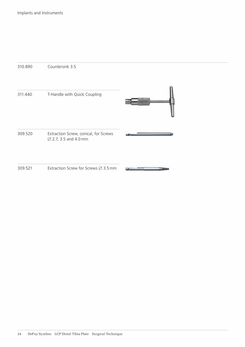
If a screw cannot be removed with the screwdriver (e.g. if the hexagonal or Stardrive recess of the locking screw is damaged or if the screw is stuck in the plate), use the T-Handle with Quick-Coupling (311.440) to insert the conical Extraction Screw (309.520 or 309.521) into the screw head, and unscrew the screw in a counter-clock-wise direction.
16 DePuy Synthes LCP Distal Tibia Plate Surgical Technique
IMPLANTS AND INSTRUMENTS
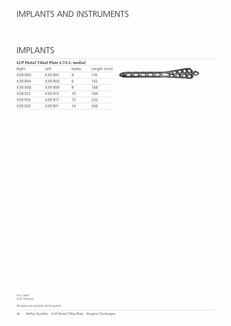
LCP Distal Tibial Plate 2.7/3.5, medial
Right Left Holes Length (mm)
X39.900 X39.901 4 116
X39.904 X39.905 6 142
X39.908 X39.909 8 168
X39.912 X39.913 10 194
X39.916 X39.917 12 220
X39.920 X39.921 14 246
IMPLANTS
X=2: Steel X=4: Titanium
All plates are available sterile packed
LCP Distal Tibia Plate Surgical Technique DePuy Synthes 17
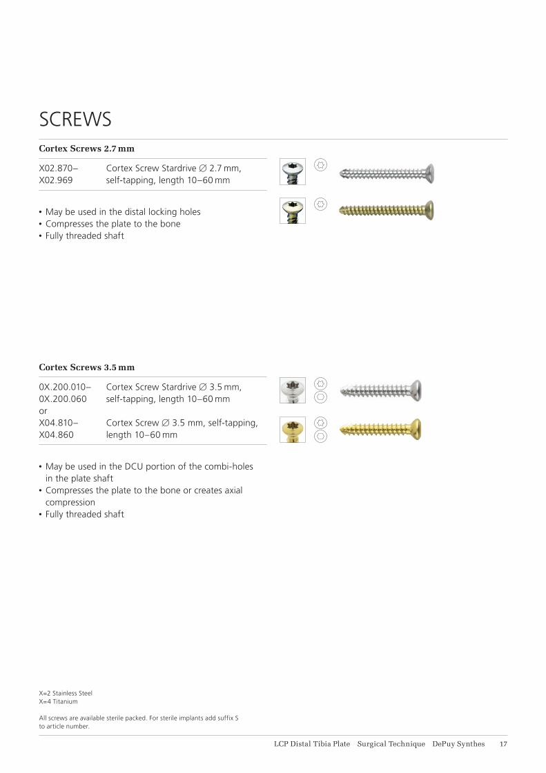
Cortex Screws 2.7 mm
X02.870– Cortex Screw Stardrive B 2.7 mm, X02.969 self-tapping, length 10–60 mm
• May be used in the distal locking holes• Compresses the plate to the bone• Fully threaded shaft
SCREWS
Cortex Screws 3.5 mm
0X.200.010– Cortex Screw Stardrive B 3.5 mm, 0X.200.060 self-tapping, length 10–60 mmorX04.810– Cortex Screw B 3.5 mm, self-tapping,X04.860 length 10–60 mm
• May be used in the DCU portion of the combi-holes
in the plate shaft• Compresses the plate to the bone or creates axial
compression• Fully threaded shaft
X=2 Stainless SteelX=4 Titanium
All screws are available sterile packed. For sterile implants add suffix S to article number.
18 DePuy Synthes LCP Distal Tibia Plate Surgical Technique
Implants and Instruments
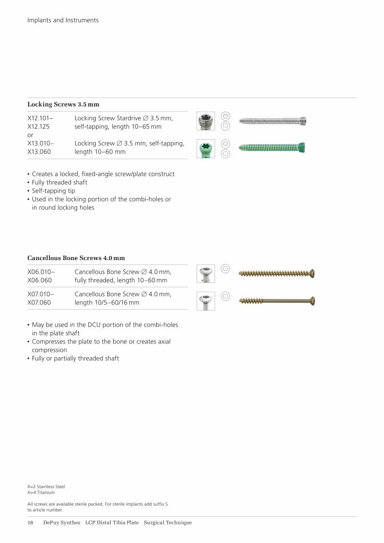
Locking Screws 3.5 mm
X12.101– Locking Screw Stardrive B 3.5 mm, X12.125 self-tapping, length 10–65 mmorX13.010– Locking Screw B 3.5 mm, self-tapping, X13.060 length 10–60 mm
• Creates a locked, fixed-angle screw/plate construct• Fully threaded shaft• Self-tapping tip• Used in the locking portion of the combi-holes or
in round locking holes
Cancellous Bone Screws 4.0 mm
X06.010– Cancellous Bone Screw B 4.0 mm, X06.060 fully threaded, length 10–60 mm
X07.010– Cancellous Bone Screw B 4.0 mm, X07.060 length 10/5–60/16 mm
• May be used in the DCU portion of the combi-holes
in the plate shaft• Compresses the plate to the bone or creates axial
compression• Fully or partially threaded shaft
X=2 Stainless SteelX=4 Titanium
All screws are available sterile packed. For sterile implants add suffix S to article number.
LCP Distal Tibia Plate Surgical Technique DePuy Synthes 19
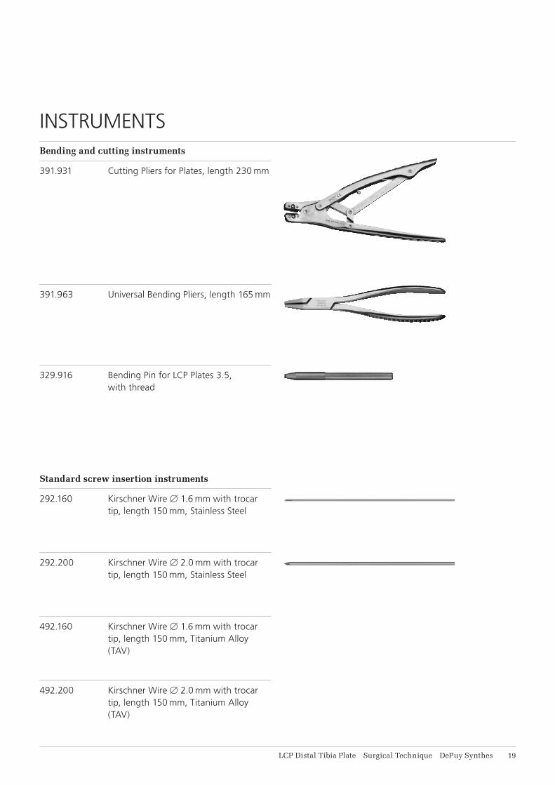
Bending and cutting instruments
391.931 Cutting Pliers for Plates, length 230 mm
Standard screw insertion instruments
292.160 Kirschner Wire B 1.6 mm with trocar tip, length 150 mm, Stainless Steel
391.963 Universal Bending Pliers, length 165 mm
329.916 Bending Pin for LCP Plates 3.5, with thread
292.200 Kirschner Wire B 2.0 mm with trocar tip, length 150 mm, Stainless Steel
492.160 Kirschner Wire B 1.6 mm with trocar tip, length 150 mm, Titanium Alloy (TAV)
492.200 Kirschner Wire B 2.0 mm with trocar tip, length 150 mm, Titanium Alloy (TAV)
INSTRUMENTS
11 DePuy Synthes LCP Distal Tibia Plate Surgical Technique
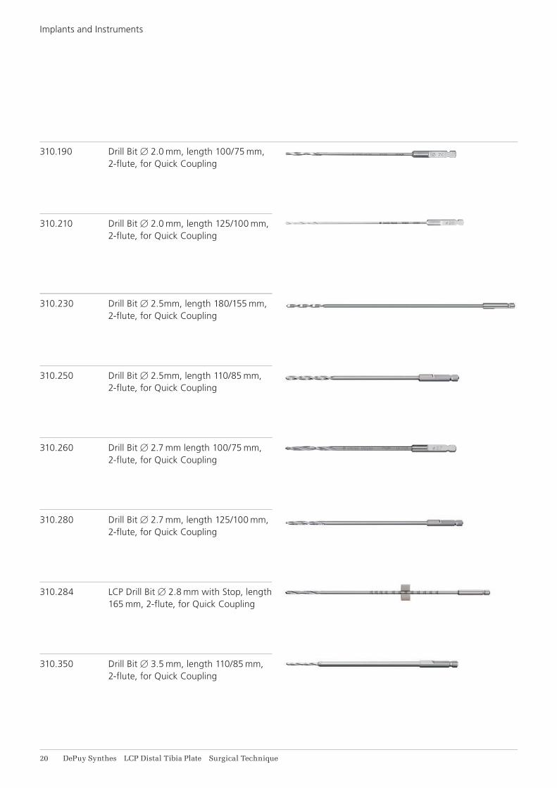
310.190 Drill Bit B 2.0 mm, length 100/75 mm, 2-flute, for Quick Coupling
310.210 Drill Bit B 2.0 mm, length 125/100 mm, 2-flute, for Quick Coupling
310.230 Drill Bit B 2.5mm, length 180/155 mm, 2-flute, for Quick Coupling
310.250 Drill Bit B 2.5mm, length 110/85 mm, 2-flute, for Quick Coupling
310.260 Drill Bit B 2.7 mm length 100/75 mm, 2-flute, for Quick Coupling
310.280 Drill Bit B 2.7 mm, length 125/100 mm, 2-flute, for Quick Coupling
310.284 LCP Drill Bit B 2.8 mm with Stop, length 165 mm, 2-flute, for Quick Coupling
310.350 Drill Bit B 3.5 mm, length 110/85 mm, 2-flute, for Quick Coupling
Implants and Instruments
LCP Distal Tibia Plate Surgical Technique DePuy Synthes 11
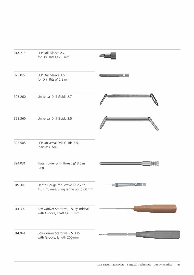
323.260 Universal Drill Guide 2.7
323.360 Universal Drill Guide 3.5
323.505 LCP Universal Drill Guide 3.5, Stainless Steel
313.302 Screwdriver Stardrive, T8, cylindrical, with Groove, shaft B 3.5 mm
324.031 Plate Holder with thread B 3.5 mm, long
314.041 Screwdriver Stardrive 3.5, T15, with Groove, length 200 mm
319.010 Depth Gauge for Screws B 2.7 to 4.0 mm, measuring range up to 60 mm
312.922 LCP Drill Sleeve 2.7, for Drill Bits B 2.0 mm
323.027 LCP Drill Sleeve 3.5, for Drill Bits B 2.8 mm
11 DePuy Synthes LCP Distal Tibia Plate Surgical Technique
511.770 Torque Limiter, 1.5 Nm, for Compact Air Drive and Power Drive
511.773 Torque Limiter, 1.5 Nm, for AO/ASIF Quick Coupling
397.705 Handle for Torque Limiter Nos. 511.770 and 511.771
Implants and Instruments
314.020 Screwdriver, hexagonal, small, with Holding Sleeve
314.030 Screwdriver Shaft, hexagonal, small, B 2.5 mm
314.467 Screwdriver Shaft, Stardrive, T8, self-holding
314.116 Screwdriver Shaft Stardrive 3.5, T15, self-holding, for AO/ASIF Quick Coupling
LCP Distal Tibia Plate Surgical Technique DePuy Synthes 11
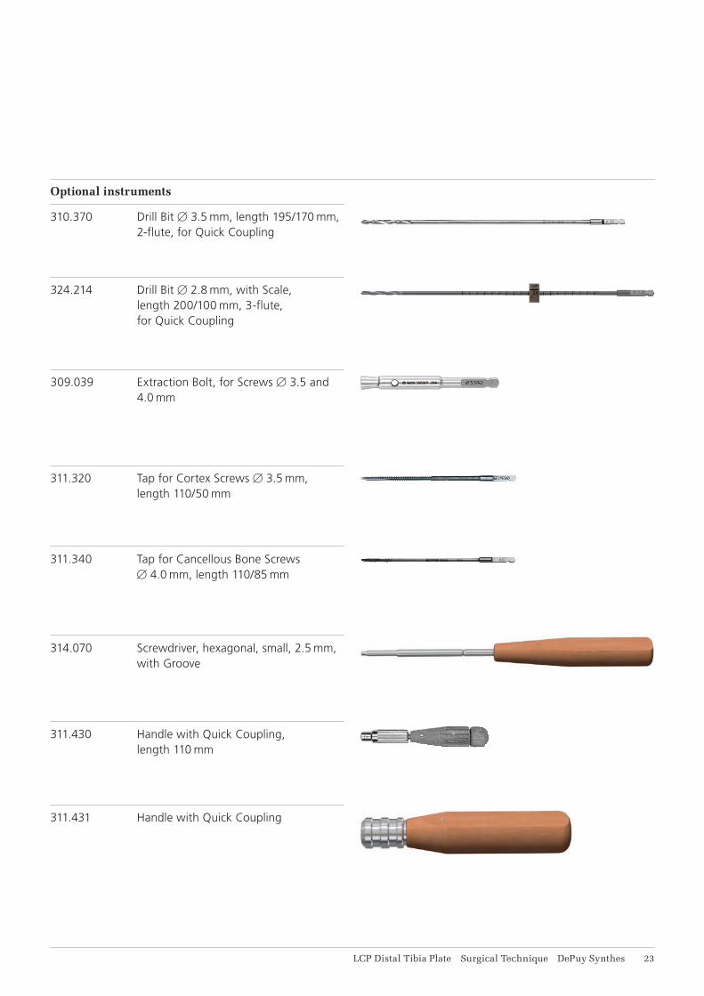
324.214 Drill Bit B 2.8 mm, with Scale, length 200/100 mm, 3-flute, for Quick Coupling
309.039 Extraction Bolt, for Screws B 3.5 and 4.0 mm
311.320 Tap for Cortex Screws B 3.5 mm, length 110/50 mm
311.340 Tap for Cancellous Bone Screws B 4.0 mm, length 110/85 mm
314.070 Screwdriver, hexagonal, small, 2.5 mm, with Groove
311.430 Handle with Quick Coupling, length 110 mm
311.431 Handle with Quick Coupling
Optional instruments
310.370 Drill Bit B 3.5 mm, length 195/170 mm, 2-flute, for Quick Coupling
14 DePuy Synthes LCP Distal Tibia Plate Surgical Technique
Implants and Instruments
310.890 Countersink 3.5
311.440 T-Handle with Quick Coupling
309.520 Extraction Screw, conical, for Screws B 2.7, 3.5 and 4.0 mm
309.521 Extraction Screw for Screws B 3.5 mm
LCP Distal Tibia Plate Surgical Technique DePuy Synthes 15
MRI INFORMATION
Torque, Displacement and Image Artifacts according to ASTM F 2213-06, ASTM F 2052-06e1 and ASTM F 2119-07Non-clinical testing of worst case scenario in a 3 T MRI system did not reveal any relevant torque or displace-ment of the construct for an experimentally measured local spatial gradient of the magnetic field of 3.69 T/m. The largest image artifact extended approximately 169 mm from the construct when scanned using the Gradient Echo (GE). Testing was conducted on a 3 T MRI system.
Radio-Frequency-(RF-)induced heating according to ASTM F 2182-11aNon-clinical electromagnetic and thermal testing of worst case scenario lead to peak temperature rise of 9.5 °C with an average temperature rise of 6.6 °C (1.5 T) and a peak temperature rise of 5.9 °C (3 T) under MRI Conditions using RF Coils (whole body averaged specific absorption rate [SAR] of 2 W/kg for 6 minutes [1.5 T] and for 15 minutes [3 T]).
Precautions: The above mentioned test relies on non-clinical testing. The actual temperature rise in the patient will depend on a variety of factors beyond the SAR and time of RF application. Thus, it is recommended to pay particular attention to the following points: • It is recommended to thoroughly monitor patients
undergoing MR scanning for perceived tempera-ture and/or pain sensations.
• Patients with impaired thermoregulation or temperature sensation should be excluded from MR scanning procedures.
• Generally, it is recommended to use a MR system with low field strength in the presence of conduc-tive implants. The employed specific absorption rate (SAR) should be reduced as far as possible.
• Using the ventilation system may further contrib-ute to reduce temperature increase in the body.

0123
Synthes GmbHEimattstrasse 34436 OberdorfSwitzerlandTel: +41 61 965 61 11Fax: +41 61 965 66 00www.depuysynthes.com
Not all products are currently available in all markets.
This publication is not intended for distribution in the USA.
All surgical techniques are available as PDF files at www.depuysynthes.com/ifu ©
DeP
uy S
ynth
es T
raum
a, a
div
isio
n of
Syn
thes
Gm
bH. 2
016.
A
ll rig
hts
rese
rved
. 03
6.00
0.37
6 D
SE
M/T
RM
/081
5/04
73(1
) 03
/16