Embed Size (px)
Citation preview
ARTICLE IN PRESS
0168-9002/$ - se
doi:10.1016/j.ni
�CorrespondE-mail addr
Nuclear Instruments and Methods in Physics Research A 575 (2007) 22–28
www.elsevier.com/locate/nima
LCLS undulator—recent developments: Undulator tapering tocompensate for particle energy loss (simulations, continuous case).
First article measurements and tuning
I.B. Vassermana,�, R.J. Dejusa, S. Sasakia, J.Z. Xua, E.M. Trakhtenberga, S.V. Miltona,E.R. Mooga, M.M. Whitea, N.A. Vinokurovb
aAdvanced Photon Source, Argonne National Laboratory, Argonne, IL 60439, USAbBudker Institute of Nuclear Physics, 630090 Novosibirsk, Russia
Available online 10 January 2007
Abstract
Computer simulations using a continuous change in particle energy are an important tool in improving the performance at the final
stage of the Linac Coherent Light Source (LCLS) undulator line. Changes in the particle energy cause the break length between
undulator segments to no longer be optimized. Radiation losses less than 0.1%/undulator segment can be easily compensated
by adjustment of an undulator deflection parameter K. For higher losses, up to 0.4%, adjustment of K can still be compensated,
but careful optimization is required. Compensating for losses greater than 0.4% requires tapering of the field within the undulator
segment. The LCLS undulator segments are in mass production at this time. The first two undulators for the LCLS project were
delivered to the APS magnetic measurement facility. They have already been tuned, and meet all requirements for the LCLS free-electron
laser (FEL). The final results of this tuning will be presented, with emphasis on the FEL-specific requirements. A systematic zero shift in
the Sentron [/http://www.sentron.ch/S. [1]] 2-axis Hall probe was discovered, which required correction in order to obtain the proper
field integrals.
r 2007 Elsevier B.V. All rights reserved.
PACS: 85.70; 07.55G; 07.85.Q
Keywords: Hybrid undulator; Synchrotron radiation; SASE
1. Introduction
The Linac Coherent Light Source (LCLS) is a colla-boration between four US-DOE national laboratories,and will be located at the Stanford Linear Accele-rator Center (SLAC) in Stanford, CA. A prototypeLCLS undulator segment [2] was built, measured, andtuned during the past several years at the AdvancedPhoton Source in Argonne National Laboratory. Manyupgrades were applied to the first design, includingimprovements to the strongback, use of canted poles,
e front matter r 2007 Elsevier B.V. All rights reserved.
ma.2007.01.011
ing author. Tel.: +1630 252 9612; fax: +1 630 252 9303.
ess: [email protected] (I.B. Vasserman).
novel types of shims, a mu-metal shield around thetitanium core, and others.Most of the improvements were implemented fully or
partially in the prototype undulator. It was decided tocarefully test and tune the first two articles at the APS inorder to be sure that many improvements were adequatelyimplemented in mass production. All subsequent devices willbe tuned at SLAC. First investigation of LCLS tolerances wasperformed using the constant particle energy approach. Thenext step was done with a step function energy change fromone segment to another using all particle loss mechanismsknown so far [3]. Most recently, the most realistic assumptionof continuous particle energy loss along the beamline is made.LCLS parameters are shown in Table 1.
ARTICLE IN PRESS
Table 1
LCLS undulator parameters
Particle energy 13.64GeV
Undulator type Planar hybrid
Magnet material NdFeB
Gap 6.8mm
Period length 30mm
Range of effective undulator
parameter Keff
3.5–3.479 (0.6%)
Number of segments 33
Segment length 3.4m
Standard break length 47–47–89.8 cm (2–2–4 pattern)
0 5000 1.104 1.5.104 2.104 2.5.104 3.104 3.5.104 4.1040
5
15
20
ER11k1 ER12k2ER13k3 ER14k4
k1,k2,k3,k4,10
Fig. 1. Calculated values of jAj, the magnitude of the radiation amplitude,
are shown as a function of z. The calculation is for four undulator
segments with an energy loss of DE/E 1.3� 10�4/3.4-m-long segment.
Radiation amplitude modulus jAj at the end is �10% lesser than for the
case with no energy loss.
0 17.5
30
60
90
120
150
210
240 300
330
15
10
5
0ER11k9180
I.B. Vasserman et al. / Nuclear Instruments and Methods in Physics Research A 575 (2007) 22–28 23
2. Simulations
Equations for complex amplitude of radiation fromRef. [4] are rewritten for the variable-energy case:
AðzÞ ¼
Z z
0
I1yðz0Þe�ijðz
0Þ dz0
and phase slippage
jðzÞ ¼k
2
Z z
0
dz0
gðz0Þ2þ
Z z
0
I21xðz0Þdz0 þ
Z z
0
I21yðz0Þdz0
� �
where k is the fundamental harmonic wave vector ofradiation, g the relativistic factor, and I1y,x are particleangles:
I1yðzÞ ¼e
gðzÞmc2
Z z
0
Byðz0Þdz0 �
1
L
Z L
0
Z z0
0
Byðz00Þdz00
� �dz0
� �
The spectral intensity of spontaneous radiation isproportional to jAj. The value of jAj is a convenient figureof merit in an undulator optimization (see Ref. [4] forexplanations). Applying these formulas to a set ofundulator sections, separated by breaks, one can obtainthe optimal values of break lengths. These optimal lengthscorrespond to slippage of particles with respect to wave byinteger number of radiation wavelengths. In the LCLSthese numbers vary periodically, as 2, 2, 4, 2, 2, 4, 2,y.But, the optimal lengths depend on particle energy, whichdecreases due to different kinds of loss. Data from theprototype were used to simulate four devices in a row. Thebreak length pattern 2–2–4 was used for the undulator linewith all lengths fixed. Different options were considered:
270ER1k9
1.
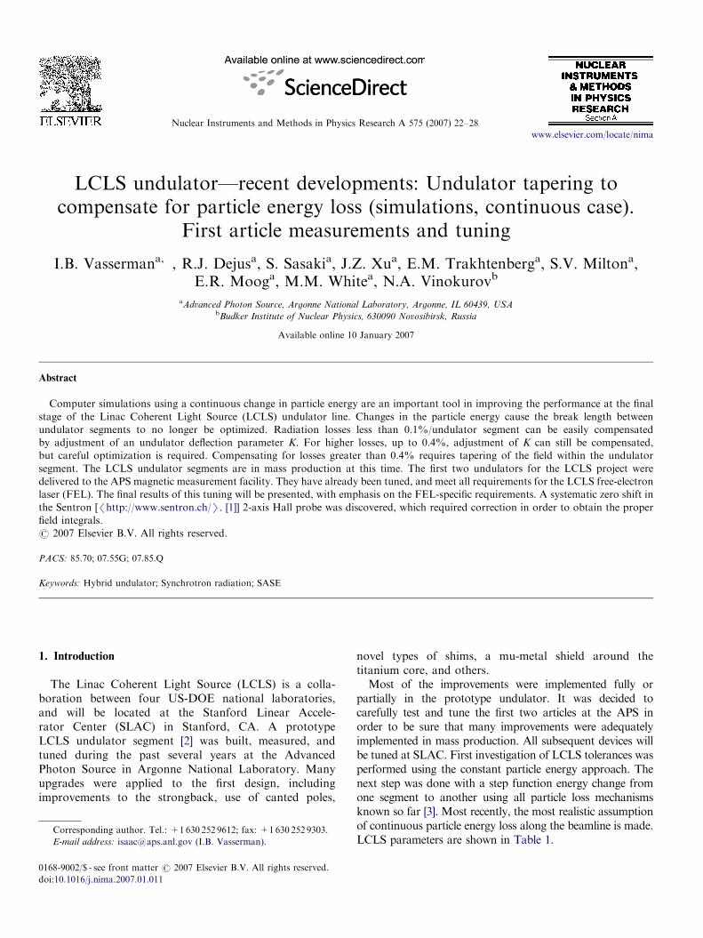
Fig. 2. Polar plot of the results shown in the Fig. 1. The curvature of theline is a result of phase slippage in the device due to particle energy loss.
Four segments are located in the initial part of thebeamline with energy E ¼ 13.64GeV and particle energyloss 1.3� 10�4/device (Figs. 1 and 2);
The effect of phase slippage is made more visible using this representation
technique. The magnitude of the complex radiation amplitude jAj at the
2.end of the line of undulators is represented by the distance from the origin
to the end of the curve. The radiation intensity is proportional to jAj2.
Four segments are located at 90m from the beginning ofbeamline with initial energy changed by 0.4% and thesame particle energy loss 1.3� 10�4/device (Fig. 3);
3.
Same as 1 with particle energy loss 0.1%/device (Fig. 4); 4. Same as 1 with particle energy loss 0.4%/device, Fig. 5).Due to energy loss, phasing between devices set for oneparticular particle energy becomes distorted with energy
change. Polar plots use the presentation of complexradiation amplitude in the form
AðzÞ ¼ jAj expðijðzÞÞ.
ARTICLE IN PRESS
0 17.5
30
60
90
120
150
210
240
270
300
330
15
10
5
0ER11k9180
ER1k9
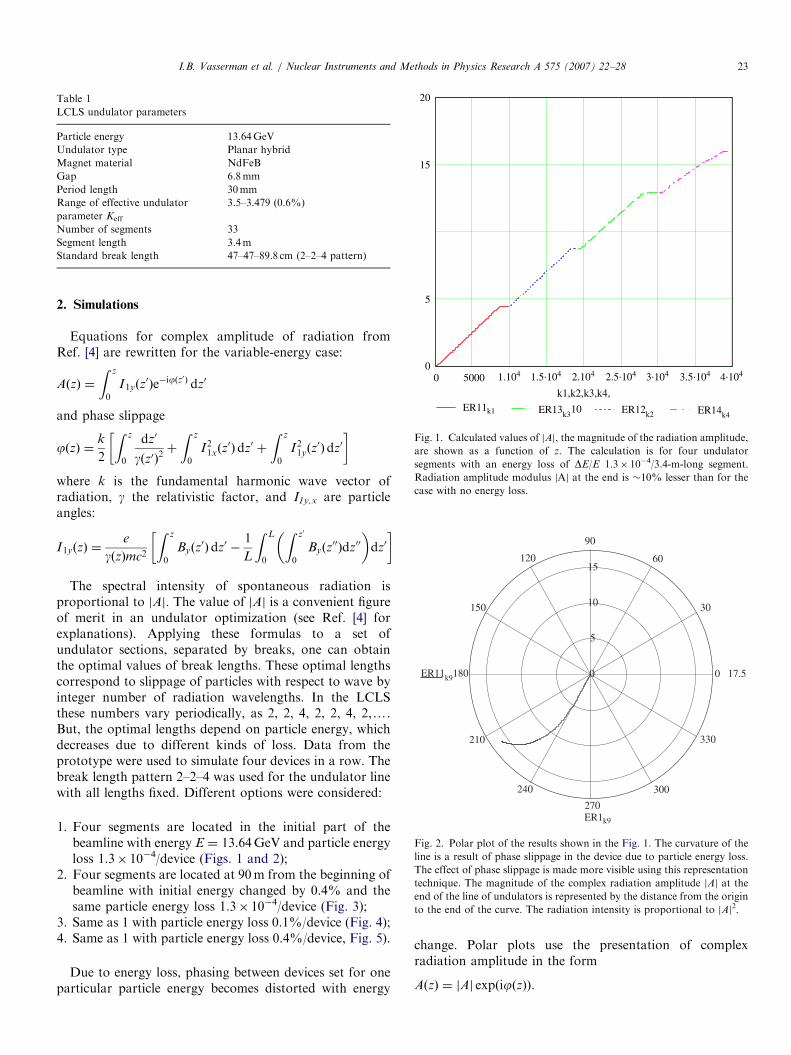
Fig. 3. The initial particle energy was changed from the initial 13.64GeV
by 0.4%. The effect of the break-length error gets worse as the energy
deviates further from its initial value, making the kinks at the breaks
become more pronounced. K is corrected to compensate for electron
energy loss (i.e., to hold the photon wavelength constant). The energy loss
per device is the same as before (1.3� 10�4). Degradation of jAj is �2.0%
due to break-length distortions.
0
30
60
90
120
150
210
240
270
300
330
15
10
5
0ER11k9180
ER1k9
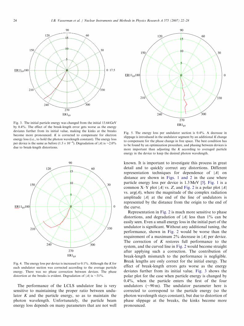
Fig. 4. The energy loss per device is increased to 0.1%. Although the K for
each undulator section was corrected according to the average particle
energy. There was no phase correction between devices. The phase
distortion at the breaks is evident. Degradation of jAj is �31%.
0
30
60
90
120
150
210
240
270
300
330
15
10
5
0ER11k9180
ER1k9
Fig. 5. The energy loss per undulator section is 0.4%. A decrease in
slippage is introduced in the undulator segment by an additional K change
to compensate for the phase change in free space. The best condition has
to be found by an optimization procedure, and phasing between devices is
more important than adjusting the K according to averaged particle
energy in the device to keep the desired photon wavelength.
I.B. Vasserman et al. / Nuclear Instruments and Methods in Physics Research A 575 (2007) 22–2824
The performance of the LCLS undulator line is verysensitive to maintaining the proper ratio between undu-lator K and the particle energy, so as to maintain thephoton wavelength. Unfortunately, the particle beamenergy loss depends on many parameters that are not well
known. It is important to investigate this process in greatdetail and to quickly correct any distortions. Differentrepresentation techniques for dependence of jAj ondistance are shown in Figs. 1 and 2 in the case whereparticle energy loss per device is 1.3MeV [5]. Fig. 1 is acommon X–Y plot jAj vs. Z, and Fig. 2 is a polar plot jAjvs. arg(A), where the magnitude of the complex radiationamplitude jAj at the end of the line of undulators isrepresented by the distance from the origin to the end ofthe curve.Representation in Fig. 2 is much more sensitive to phase
distortions, and degradation of jAj less than 1% can beeasily seen. Even a small energy loss in the initial part of theundulator is significant. Without any additional tuning, theperformance, shown in Fig. 2 would be worse than therequirement of a maximum 2% decrease in jAj per device.The correction of K restores full performance to thesystem, and the curved line in Fig. 2 would become straightafter applying such a correction. The contribution ofbreak-length mismatch to the performance is negligible.Break lengths are only correct for the initial energy. Theeffect of break-length errors gets worse as the energydeviates further from its initial value. Fig. 3 shows thepolar plot for the case when particle energy is changed by0.4%, when the particle enters the first of the fourundulators (�90m). The undulator parameter here iscorrected to correspond to the particle energy (so thephoton wavelength stays constant), but due to distortion ofphase slippage at the breaks, the kinks become morepronounced.
ARTICLE IN PRESSI.B. Vasserman et al. / Nuclear Instruments and Methods in Physics Research A 575 (2007) 22–28 25
Free-electron laser (FEL) bunching will result in a muchlarger coherent radiation loss. Saturation itself is a rathercomplicated process, and tapering to compensate only forradiation losses does not give maximum radiation energyoutput. The case of higher radiation loss that follows showshow different energy loss levels will affect the resultsdescribed above (see Fig. 4). This figure shows the case,when energy loss/device is 0.1%, or 13.6MeV/device. K hasbeen corrected for each undulator section according to theaverage particle energy, as shown in Fig. 4. There is nophase correction between devices. The phase distortion atthe breaks is evident. Degradation of jAj is �31%. There isa simple way of compensating this distortion instead of thecommonly used correction of phase between devices byapplying a phase shifter. If a small slippage is introduced inthe undulator segments by decreasing K to compensate forthe phase change in free space, the degradation of jAjbecomes only 1.6%, which is still lesser than tolerances(2% for one device).
The previous discussion covers most of the assumedLCLS parameters. For comparative purposes, Fig. 5 showsthe case with very high energy losses (0.4%) per device. TheK value for the undulator sections was chosen to optimizeoverall performance.
In Fig. 5 K was corrected for each undulator sectionaccording to the average particle energy. Distances betweendevices are uncorrected. Phase distortion at the breaks ishuge. Performance degraded by �50%. Calculationsshow that correction of A introduced in the undulatorsegment by an additional K change to compensate for thephase change in free space does not restore performance infull in this case. The best that can be achieved here byoptimizing the performance using K only achieves 8.5%degradation of [A]. To further improve the performance,continuous tapering can be provided using the canteddevice option by shifting the ends of the undulator sectionin opposite directions. With a cant of 4.5mrad, therequired shift at the ends should be 71.7mm for anenergy loss of 0.4%/device. It is possible to increase thecant near the end part of the undulator line, wheresaturation should start, so the shift is smaller. The tuningin this case should take into account the real trajectorypath through the device. Real energy loss at the final stage,when saturation starts, is unknown, so the numbers usedabove are arbitrary to show the possible scenarios fordifferent cases. To obtain more reliable results, simulationsinvolving real particle beam parameters and bunchingeffects have to be performed including all sources ofcontinuous particle energy loss and different taperingoptions to optimize power output.
3. LCLS article #1 measurements and tuning
Upgrades of all measurement systems were done [6]before tuning, including: Hall probe and moving coil; longintegration coil with rotation and translation modes; andstretched wire. The new system allows for quick and
reliable real-time measurements; only a single measurementis required in most cases due to the perfect reproducibility.A fine spacing of data points, limited only by the resolutionof the encoder, is possible. High speed (up to 75mm/s) isused for Hall probe and moving coil measurements.Reproducibility of effective magnetic field measurementsis 0.1G at the level of 12500G.The Earth’s field effect is an important factor due to
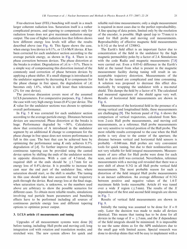
concentration of the field in the undulator by the highmagnetic permeability poles by a factor of 2.4. Simulationswith the code Radia and magnetic measurements [7,8]were carried out. Even a 0.05-G difference in the Earth’sfield at the tunnel from what is present in the magneticmeasurement facility during tuning will result in un-acceptable trajectory distortion. Measurements of thefield in the tunnel are complicated and time consuming.A solution was proposed to decrease this effect dra-matically by wrapping the undulator with a mu-metalshield. This damps the field by a factor of 8. The calculatedand measured signatures of the shield agree very well.Results of horizontal field measurements are shown inFig. 6.Measurements of the horizontal field in the presence of a
strong vertical and longitudinal fields, these measurementsare challenging [9]. The bottom panel of Fig. 6 shows thecomparison of vertical trajectories, calculated from Sen-tron 2-axis Hall probe measurements, and moving coilmeasurements, as a reference. Hall probe measurementsare very sensitive to vertical position of the Hall probe. Themost reliable results correspond to the case when the Hallprobe is very close to the center of the aperture; thedistance between vertical and horizontal field sensors isprobably �0.048mm. Hall probes are very convenienttools for quick tuning, but due to their nonlinearities arenot very reliable for field integral measurements. Measure-ments of zero offset for Hall probe were done for eachscan, and zero drift was corrected. Nevertheless, referencemeasurements with a moving coil revealed that there was azero shift of about 0.3G in all Hall probe vertical fieldmeasurements. The most probable reason for such adistortion of the field integral Hall probe measurementsis an inexact calibration. An average difference of 0.3Gbetween positive and negative values of the 1.4-Tmaximum fields looks reasonable. Article #1 was tunedover a wide X region (75mm). The results of the X
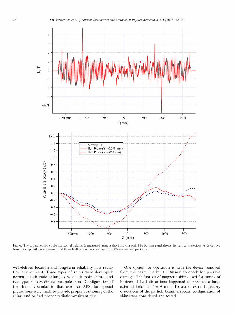
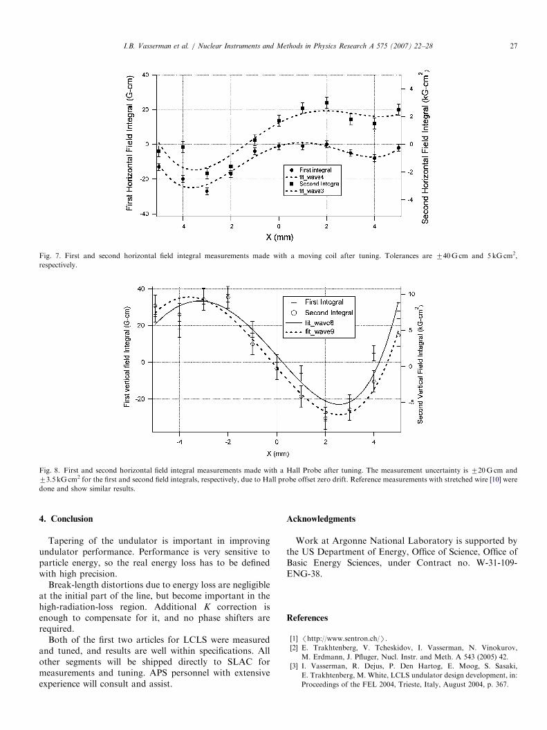
dependence of the first and second field integrals are shownin Fig. 7.Results of vertical field measurements are shown in
Fig. 8.Initially the tuning was assumed to be done for X ¼ 0
only. Later the decision was made to make all devicesidentical. This means that tuning has to be done for alldevices in the range of X ¼75mm, and the X dependenceof the field integrals should be minimized. It is impossibleto use the same shims as for the APS undulators due tothe small gap with limited access. Special research wasdone to develop shims that will be easy to implement with a
ARTICLE IN PRESS
Fig. 6. The top panel shows the horizontal field vs. Z measured using a short moving coil. The bottom panel shows the vertical trajectory vs. Z derived
from moving-coil measurements and from Hall probe measurements at different vertical positions.
I.B. Vasserman et al. / Nuclear Instruments and Methods in Physics Research A 575 (2007) 22–2826
well-defined location and long-term reliability in a radia-tion environment. Three types of shims were developed:normal quadrupole shims, skew quadrupole shims, andtwo types of skew dipole-sextupole shims. Configuration ofthe shims is similar to that used for APS, but specialprecautions were made to provide proper positioning of theshims and to find proper radiation-resistant glue.
One option for operation is with the device removedfrom the beam line by X ¼ 80mm to check for possibledamage. The first set of magnetic shims used for tuning ofhorizontal field distortions happened to produce a largeexternal field at X ¼ 80mm. To avoid extra trajectorydistortions of the particle beam, a special configuration ofshims was considered and tested.
ARTICLE IN PRESS
Fig. 7. First and second horizontal field integral measurements made with a moving coil after tuning. Tolerances are 740G cm and 5 kGcm2,
respectively.
Fig. 8. First and second horizontal field integral measurements made with a Hall Probe after tuning. The measurement uncertainty is 720Gcm and
73.5 kGcm2 for the first and second field integrals, respectively, due to Hall probe offset zero drift. Reference measurements with stretched wire [10] were
done and show similar results.
I.B. Vasserman et al. / Nuclear Instruments and Methods in Physics Research A 575 (2007) 22–28 27
4. Conclusion
Tapering of the undulator is important in improvingundulator performance. Performance is very sensitive toparticle energy, so the real energy loss has to be definedwith high precision.
Break-length distortions due to energy loss are negligibleat the initial part of the line, but become important in thehigh-radiation-loss region. Additional K correction isenough to compensate for it, and no phase shifters arerequired.
Both of the first two articles for LCLS were measuredand tuned, and results are well within specifications. Allother segments will be shipped directly to SLAC formeasurements and tuning. APS personnel with extensiveexperience will consult and assist.
Acknowledgments
Work at Argonne National Laboratory is supported bythe US Department of Energy, Office of Science, Office ofBasic Energy Sciences, under Contract no. W-31-109-ENG-38.
References
[1] /http://www.sentron.ch/S.
[2] E. Trakhtenberg, V. Tcheskidov, I. Vasserman, N. Vinokurov,
M. Erdmann, J. Pfluger, Nucl. Instr. and Meth. A 543 (2005) 42.
[3] I. Vasserman, R. Dejus, P. Den Hartog, E. Moog, S. Sasaki,
E. Trakhtenberg, M. White, LCLS undulator design development, in:
Proceedings of the FEL 2004, Trieste, Italy, August 2004, p. 367.

ARTICLE IN PRESSI.B. Vasserman et al. / Nuclear Instruments and Methods in Physics Research A 575 (2007) 22–2828
[4] E. Gluskin, N.A. Vinokurov, G. Decker, R.J. Dejus, P. Emma,
P. Ilinsky, E.R. Moog, H.-D. Nuhn, I.B. Vasserman, Nucl. Instr. and
Meth. A 475 (2001) 323.
[5] Z. Huang, G. Stupakov, Phys. Rev. ST–Accel. Beams 8 (2005)
040702.
[6] J.Z. Xu, I. Vasserman, A new magnetic field integral measurement
system, PAC 2005, Knoxville, TN, USA, May 2005, p. 1808.
[7] O. Chubar, P. Elleaume, J. Chavanne, J. Synchrotron Radiat. 5
(1998) 481.
[8] S. Sasaki, I.B. Vasserman, Modeling the effect of the earth’s field
and an iron plate on the LCLS Undulator Trajectory, in: Pro-
ceedings of the 2005 FEL Conference, Stanford, CA, August 2005,
p. 207.
[9] I. Vasserman, Test of horizontal field measurements in the presence
of a strong vertical field, in: Proceedings of the 2004 FEL Conference,
Trieste, Italy, August 2004, p. 527.
[10] D. Zangrando, R.P. Walker, Nucl. Instr. and Meth. A 376 (1996)
275.