Embed Size (px)
Citation preview
The copyright belongs to InnoLux. Any unauthorized use is prohibited.
INNOLUX DISPLAY CORPORATION LCD MODULE
SPECIFICATION
Customer:
Model Name:
AT043TN24 V.1
SPEC NO.: A043-24-TT-11
Date: 2008/04/07
Version: 01
Preliminary Specification
Final Specification
Remark
Touch Screen Panel (3-in-1FPC)
For Customer ’s Acceptance
Approved by Comment
Approved by Reviewed by Prepared by
Joe Lin
2008/04/09
James Yu
2008/04/07
Kevin Chen
2008/04/07
INNOLUX
The copyright belongs to InnoLux. Any unauthorized use is prohibited.
InnoLux copyright 2004 All rights reserved, Copying forbidden.
Record of Revision
Version Revise Date Page Content
Pre-spec.01 2008/04/07 Initial Release.
INNOLUX
The copyright belongs to InnoLux. Any unauthorized use is prohibited.
Contents
1. General Specifications………………………………………………………………………………...1
2. Pin Assignment…………………………………………………………………………………………2
2.1. TFT LCD Panel Driving Section......................................................................................2
2.2. Touch Screen Panel Section............................................................................................4
3. Operation Specifications………………………………………………………………………………5
3.1. Absolute Maximum Ratings ............................................................................................5
3.2. Typical operation conditions ...........................................................................................6
3.3 Backlight Driving Conditions ..........................................................................................6
3.4. Power Sequence ............................................................................................................7
3.5. Timing Characteristics ....................................................................................................8
3.5.1. Timing Conditions....................................................................................................8
3.5.2. Timing Diagram .....................................................................................................10
4. Touch Screen Panel Specifications…………………………………………………………………12
4.1. Electrical Characteristics ..............................................................................................12
4.2. Mechanical & Reliability Characteristics ........................................................................13
4.3. Linearity Definition .........................................................................................................14
4.4. Housing design guide ………………………………………………………………………..15
5. Optical Specifications ……………………………………………………………………………….16
6. Reliability Test Items………………………………………………………………………………….20
7. General Precautions…………………………………………………………………………………21
7.1. Safety ............................................................................................................................21
7.2. Handling ........................................................................................................................21
7.3. Static Electricity..............................................................................................................21
7.4. Storage ..........................................................................................................................21
7.5. Cleaning ........................................................................................................................21
8. Mechanical Drawing………………………………………………………………………………….22
9. Package Drawing……………………………………………………………………………………..23
9.1. Packaging Material Table...............................................................................................23
9.2. Packaging Quantity........................................................................................................23
9.3. Packaging Drawing........................................................................................................24
INNOLUX SPEC NO.: A043-24-TT-11 Date : 2008/04/07
Page : 1/24
The copyright belongs to InnoLux. Any unauthorized use is prohibited.
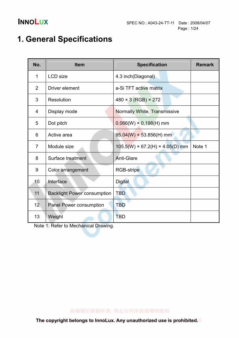
1. General Specifications
No. Item Specification Remark
1 LCD size 4.3 inch(Diagonal)
2 Driver element a-Si TFT active matrix
3 Resolution 480 × 3 (RGB) × 272
4 Display mode Normally White, Transmissive
5 Dot pitch 0.066(W) × 0.198(H) mm
6 Active area 95.04(W) × 53.856(H) mm
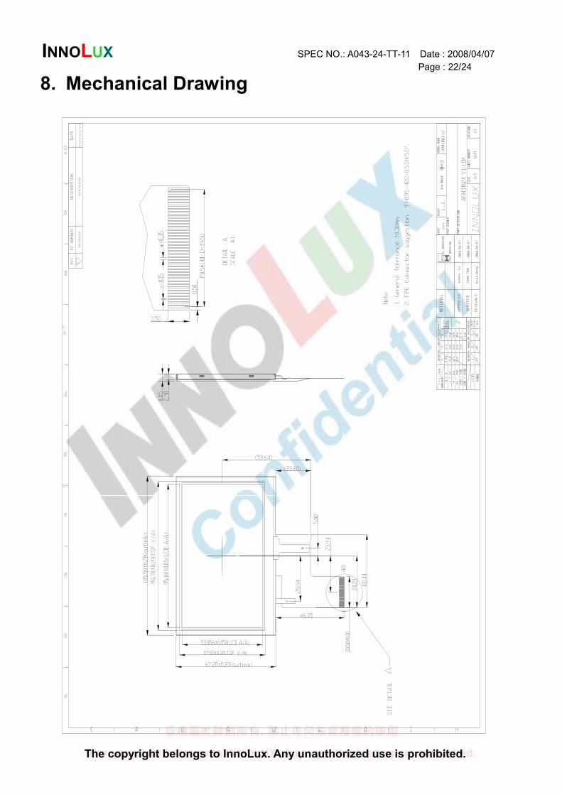
7 Module size 105.5(W) × 67.2(H) × 4.05(D) mm Note 1
8 Surface treatment Anti-Glare
9 Color arrangement RGB-stripe
10 Interface Digital
11 Backlight Power consumption TBD
12 Panel Power consumption TBD
13 Weight TBD
Note 1: Refer to Mechanical Drawing.
INNOLUX SPEC NO.: A043-24-TT-11 Date : 2008/04/07
Page : 2/24
The copyright belongs to InnoLux. Any unauthorized use is prohibited.
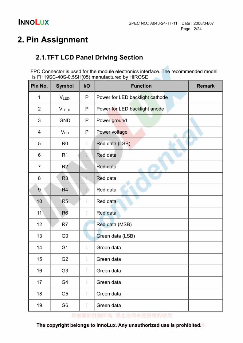
2. Pin Assignment
2.1. TFT LCD Panel Driving Section
FPC Connector is used for the module electronics interface. The recommended model is FH19SC-40S-0.5SH(05) manufactured by HIROSE.
Pin No. Symbol I/O Function Remark
1 VLED- P Power for LED backlight cathode
2 VLED+ P Power for LED backlight anode
3 GND P Power ground
4 VDD P Power voltage
5 R0 I Red data (LSB)
6 R1 I Red data
7 R2 I Red data
8 R3 I Red data
9 R4 I Red data
10 R5 I Red data
11 R6 I Red data
12 R7 I Red data (MSB)
13 G0 I Green data (LSB)
14 G1 I Green data
15 G2 I Green data
16 G3 I Green data
17 G4 I Green data
18 G5 I Green data
19 G6 I Green data
INNOLUX SPEC NO.: A043-24-TT-11 Date : 2008/04/07
Page : 3/24
The copyright belongs to InnoLux. Any unauthorized use is prohibited.
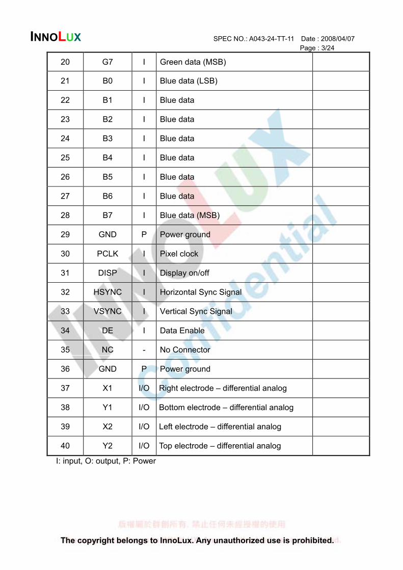
20 G7 I Green data (MSB)
21 B0 I Blue data (LSB)
22 B1 I Blue data
23 B2 I Blue data
24 B3 I Blue data
25 B4 I Blue data
26 B5 I Blue data
27 B6 I Blue data
28 B7 I Blue data (MSB)
29 GND P Power ground
30 PCLK I Pixel clock
31 DISP I Display on/off
32 HSYNC I Horizontal Sync Signal
33 VSYNC I Vertical Sync Signal
34 DE I Data Enable
35 NC - No Connector
36 GND P Power ground
37 X1 I/O Right electrode – differential analog
38 Y1 I/O Bottom electrode – differential analog
39 X2 I/O Left electrode – differential analog
40 Y2 I/O Top electrode – differential analog
I: input, O: output, P: Power
INNOLUX SPEC NO.: A043-24-TT-11 Date : 2008/04/07
Page : 4/24
The copyright belongs to InnoLux. Any unauthorized use is prohibited.
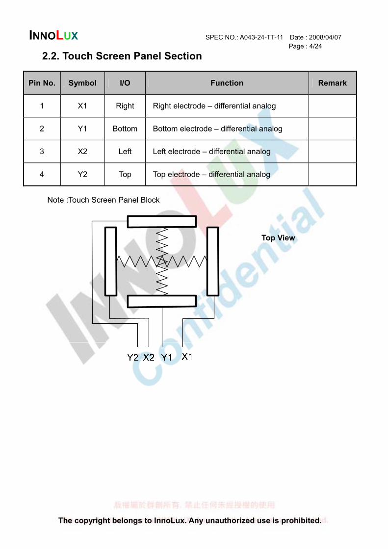
2.2. Touch Screen Panel Section
Pin No. Symbol I/O Function Remark
1 X1 Right Right electrode – differential analog
2 Y1 Bottom Bottom electrode – differential analog
3 X2 Left Left electrode – differential analog
4 Y2 Top Top electrode – differential analog
Note :Touch Screen Panel Block
Top View
INNOLUX SPEC NO.: A043-24-TT-11 Date : 2008/04/07
Page : 5/24
The copyright belongs to InnoLux. Any unauthorized use is prohibited.
()
3. Operation Specifications
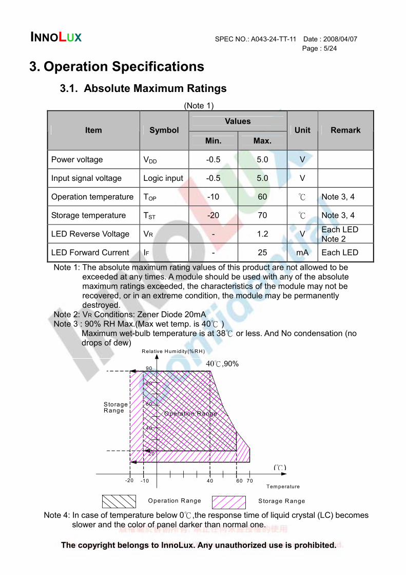
3.1. Absolute Maximum Ratings
(Note 1)
Values Item Symbol
Min. Max.
Unit Remark
Power voltage VDD -0.5 5.0 V
Input signal voltage Logic input -0.5 5.0 V
Operation temperature TOP -10 60 Note 3, 4
Storage temperature TST -20 70 Note 3, 4
LED Reverse Voltage VR - 1.2 V Each LED Note 2
LED Forward Current IF - 25 mA Each LED
Note 1: The absolute maximum rating values of this product are not allowed to be exceeded at any times. A module should be used with any of the absolute maximum ratings exceeded, the characteristics of the module may not be recovered, or in an extreme condition, the module may be permanently destroyed.
Note 2: VR Conditions: Zener Diode 20mA Note 3 : 90% RH Max.(Max wet temp. is 40 )
Maximum wet-bulb temperature is at 38 or less. And No condensation (no drops of dew)
40
20
60
90
Relative Hum idity(% RH)
Operation Range
StorageRange
-20 70Temperature
Operation Range
40
80
60
Storage Range
-10
Note 4: In case of temperature below 0,the response time of liquid crystal (LC) becomes slower and the color of panel darker than normal one.
40,90%
INNOLUX SPEC NO.: A043-24-TT-11 Date : 2008/04/07
Page : 6/24
The copyright belongs to InnoLux. Any unauthorized use is prohibited.
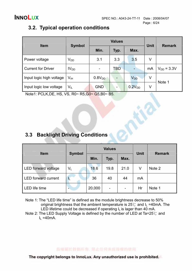
3.2. Typical operation conditions
Values Item Symbol
Min. Typ. Max.
Unit Remark
Power voltage VDD 3.1 3.3 3.5 V
Current for Driver IVDD - TBD - mA VDD = 3.3V
Input logic high voltage VIH 0.8VDD - VDD V
Input logic low voltage VIL GND - 0.2VDD V
Note 1
Note1: PCLK,DE, HS, VS, R0~ R5,G0~ G5,B0~ B5.
3.3 Backlight Driving Conditions
Values
Item Symbol
Min. Typ. Max.
Unit Remark
LED forward voltage VL 18.6 19.8 21.0 V Note 2
LED forward current IL 36 40 44 mA
LED life time - 20,000 - - Hr Note 1
Note 1: The “LED life time” is defined as the module brightness decrease to 50%
original brightness that the ambient temperature is 25 and IL =40mA. The LED lifetime could be decreased if operating IL is lager than 40 mA.
Note 2: The LED Supply Voltage is defined by the number of LED at Ta=25 and IL =40mA.
INNOLUX SPEC NO.: A043-24-TT-11 Date : 2008/04/07
Page : 7/24
The copyright belongs to InnoLux. Any unauthorized use is prohibited.
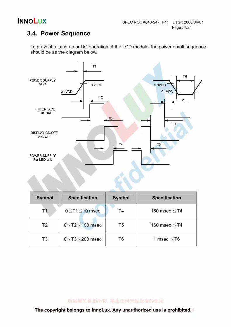
3.4. Power Sequence
To prevent a latch-up or DC operation of the LCD module, the power on/off sequence should be as the diagram below.
Symbol Specification Symbol Specification
T1 0 T1 10 msec≦ ≦ T4 160 msec T4≦
T2 0 T2 100 msec≦ ≦ T5 160 msec T4≦
T3 0 T3≦ ≦200 msec T6 1 msec T≦ 6
INNOLUX SPEC NO.: A043-24-TT-11 Date : 2008/04/07
Page : 8/24
The copyright belongs to InnoLux. Any unauthorized use is prohibited.
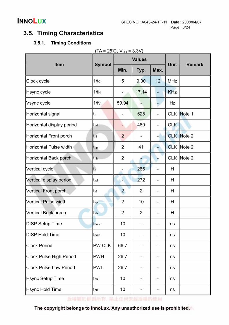
3.5. Timing Characteristics
3.5.1. Timing Conditions
(TA = 25 , VDD = 3.3V)
Values Item Symbol
Min. Typ. Max.
Unit Remark
Clock cycle 1/tC 5 9.00 12 MHz
Hsync cycle 1/fH - 17.14 - KHz
Vsync cycle 1/fV 59.94 - - Hz
Horizontal signal th - 525 - CLK Note 1
Horizontal display period thd - 480 - CLK
Horizontal Front porch thf 2 - - CLK Note 2
Horizontal Pulse width thp 2 41 - CLK Note 2
Horizontal Back porch thb 2 - - CLK Note 2
Vertical cycle tv - 286 - H
Vertical display period tvd - 272 - H
Vertical Front porch tvf 2 2 - H
Vertical Pulse width tvp 2 10 - H
Vertical Back porch tvb 2 2 - H
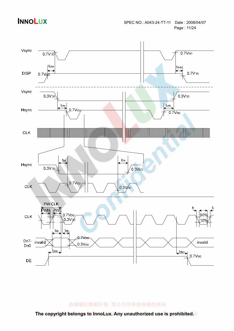
DISP Setup Time tdiss 10 - - ns
DISP Hold Time tdish 10 - - ns
Clock Period PW CLK 66.7 - - ns
Clock Pulse High Period PWH 26.7 - - ns
Clock Pulse Low Period PWL 26.7 - - ns
Hsync Setup Time ths 10 - - ns
Hsync Hold Time thh 10 - - ns
INNOLUX SPEC NO.: A043-24-TT-11 Date : 2008/04/07
Page : 9/24
The copyright belongs to InnoLux. Any unauthorized use is prohibited.
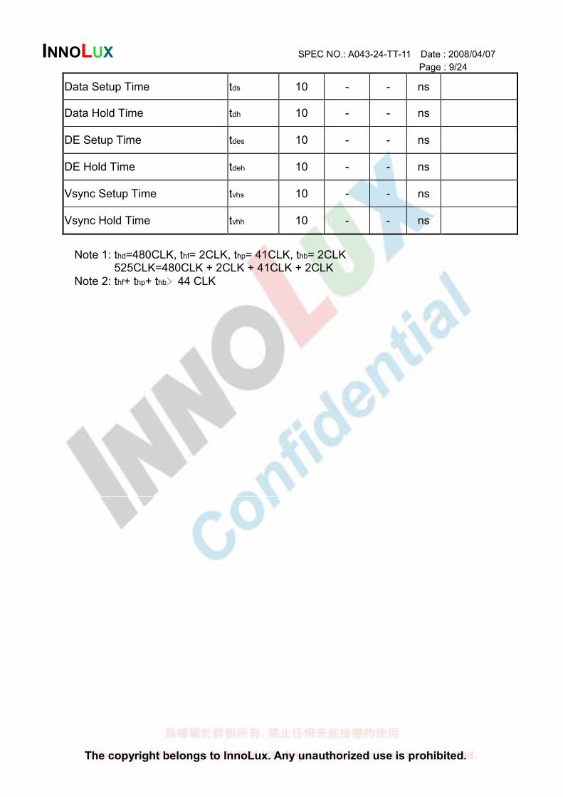
Data Setup Time tds 10 - - ns
Data Hold Time tdh 10 - - ns
DE Setup Time tdes 10 - - ns
DE Hold Time tdeh 10 - - ns
Vsync Setup Time tvhs 10 - - ns
Vsync Hold Time tvhh 10 - - ns
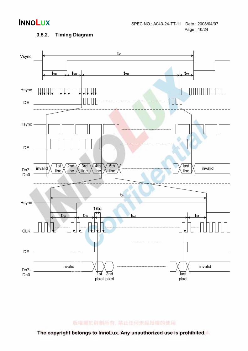
Note 1: thd=480CLK, thf= 2CLK, thp= 41CLK, thb= 2CLK
525CLK=480CLK + 2CLK + 41CLK + 2CLK Note 2: thf+ thp+ thb﹥44 CLK
INNOLUX SPEC NO.: A043-24-TT-11 Date : 2008/04/07
Page : 10/24
The copyright belongs to InnoLux. Any unauthorized use is prohibited.
3.5.2. Timing Diagram
tV
tVd tVftVbtVp
Vsync
Hsync
DE
Hsync
Hsync
DE
DE
Dn7-
Dn0
Dn7-
Dn0
CLK
invalid invalid
invalid invalid
1st
line
2nd
line
3rd
line
4th
line
5th
line
last
line
th
thp thb thd thf
1/tc
1st
pixel
2nd
pixel
last
pixel
INNOLUX SPEC NO.: A043-24-TT-11 Date : 2008/04/07
Page : 11/24
The copyright belongs to InnoLux. Any unauthorized use is prohibited.
INNOLUX SPEC NO.: A043-24-TT-11 Date : 2008/04/07
Page : 12/24
The copyright belongs to InnoLux. Any unauthorized use is prohibited.
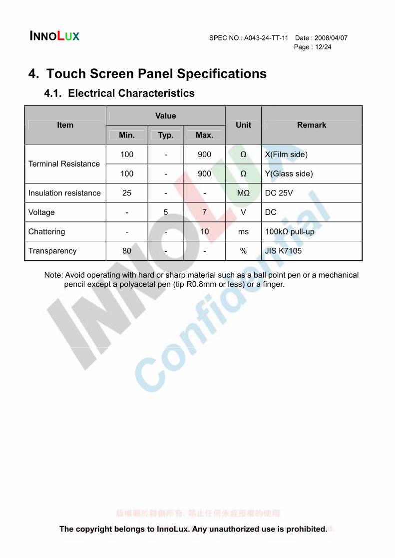
4. Touch Screen Panel Specifications
4.1. Electrical Characteristics
Value Item
Min. Typ. Max.
Unit Remark
100 - 900 Ω X(Film side) Terminal Resistance
100 - 900 Ω Y(Glass side)
Insulation resistance 25 - - MΩ DC 25V
Voltage - 5 7 V DC
Chattering - - 10 ms 100kΩ pull-up
Transparency 80 - - % JIS K7105
Note: Avoid operating with hard or sharp material such as a ball point pen or a mechanical
pencil except a polyacetal pen (tip R0.8mm or less) or a finger.
INNOLUX SPEC NO.: A043-24-TT-11 Date : 2008/04/07
Page : 13/24
The copyright belongs to InnoLux. Any unauthorized use is prohibited.
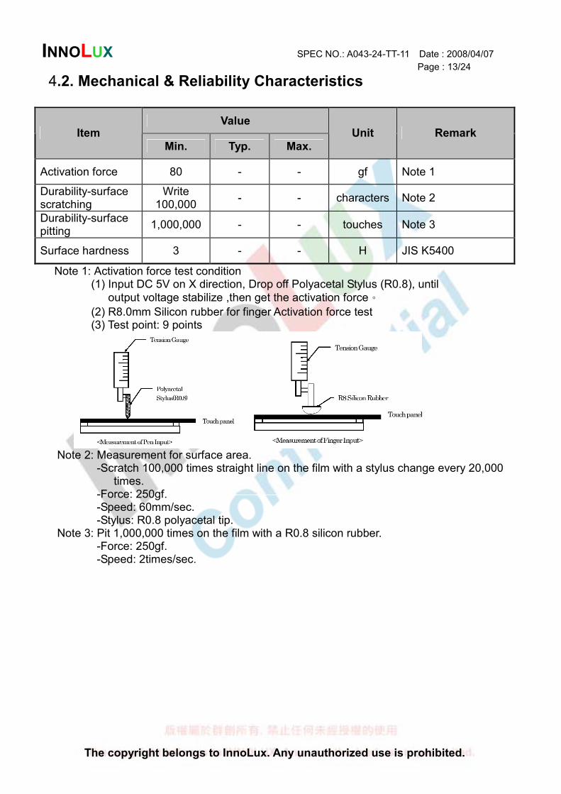
4.2. Mechanical & Reliability Characteristics
Value Item
Min. Typ. Max.
Unit Remark
Activation force 80 - - gf Note 1
Durability-surface scratching
Write 100,000
- - characters Note 2
Durability-surface pitting
1,000,000 - - touches Note 3
Surface hardness 3 - - H JIS K5400
Note 1: Activation force test condition (1) Input DC 5V on X direction, Drop off Polyacetal Stylus (R0.8), until
output voltage stabilize ,then get the activation force。
(2) R8.0mm Silicon rubber for finger Activation force test (3) Test point: 9 points
Note 2: Measurement for surface area.
-Scratch 100,000 times straight line on the film with a stylus change every 20,000 times.
-Force: 250gf. -Speed: 60mm/sec. -Stylus: R0.8 polyacetal tip. Note 3: Pit 1,000,000 times on the film with a R0.8 silicon rubber. -Force: 250gf. -Speed: 2times/sec.
INNOLUX SPEC NO.: A043-24-TT-11 Date : 2008/04/07
Page : 14/24
The copyright belongs to InnoLux. Any unauthorized use is prohibited.
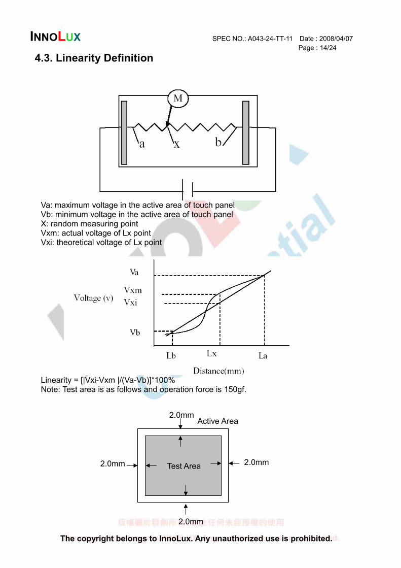
4.3. Linearity Definition
Va: maximum voltage in the active area of touch panel Vb: minimum voltage in the active area of touch panel X: random measuring point Vxm: actual voltage of Lx point Vxi: theoretical voltage of Lx point
Linearity = [|Vxi-Vxm |/(Va-Vb)]*100% Note: Test area is as follows and operation force is 150gf.
2.0mm Test Area
Active Area
2.0mm
2.0mm
2.0mm
INNOLUX SPEC NO.: A043-24-TT-11 Date : 2008/04/07
Page : 15/24
The copyright belongs to InnoLux. Any unauthorized use is prohibited.
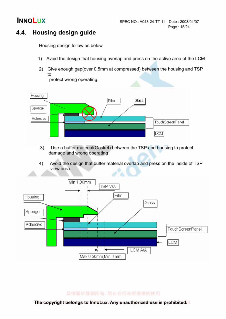
4.4. Housing design guide
Housing design follow as below
1) Avoid the design that housing overlap and press on the active area of the LCM
2) Give enough gap(over 0.5mm at compressed) between the housing and TSP
to protect wrong operating.
3) Use a buffer material(Gasket) between the TSP and housing to protect
damage and wrong operating
4) Avoid the design that buffer material overlap and press on the inside of TSP view area.
INNOLUX SPEC NO.: A043-24-TT-11 Date : 2008/04/07
Page : 16/24
The copyright belongs to InnoLux. Any unauthorized use is prohibited.
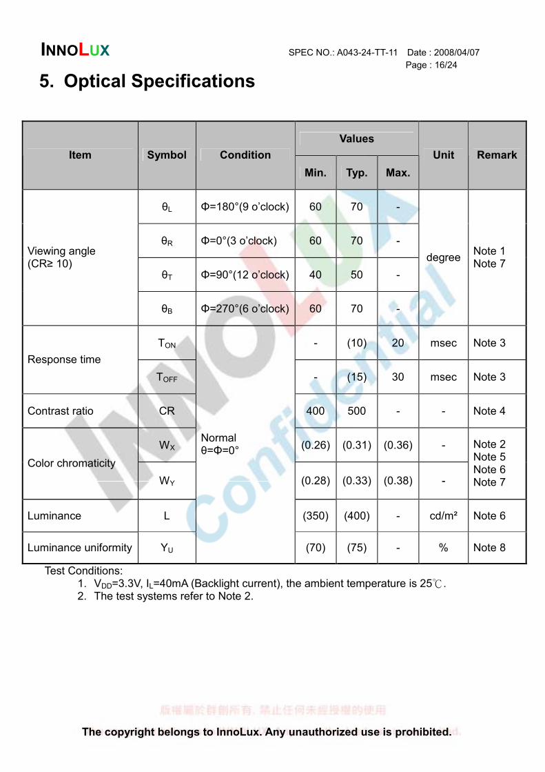
5. Optical Specifications
Values
Item Symbol Condition
Min. Typ. Max.
Unit Remark
θL Φ=180°(9 o’clock) 60 70 -
θR Φ=0°(3 o’clock) 60 70 -
θT Φ=90°(12 o’clock) 40 50 -
Viewing angle (CR≥ 10)
θB Φ=270°(6 o’clock) 60 70 -
degree Note 1 Note 7
TON - (10) 20 msec Note 3
Response time
TOFF - (15) 30 msec Note 3
Contrast ratio CR 400 500 - - Note 4
WX (0.26) (0.31) (0.36) -
Color chromaticity
WY (0.28) (0.33) (0.38) -
Note 2 Note 5 Note 6 Note 7
Luminance L (350) (400) - cd/m² Note 6
Luminance uniformity YU
Normal θ=Φ=0°
(70) (75) - % Note 8
Test Conditions: 1. VDD=3.3V, IL=40mA (Backlight current), the ambient temperature is 25 . 2. The test systems refer to Note 2.
INNOLUX SPEC NO.: A043-24-TT-11 Date : 2008/04/07
Page : 17/24
The copyright belongs to InnoLux. Any unauthorized use is prohibited.
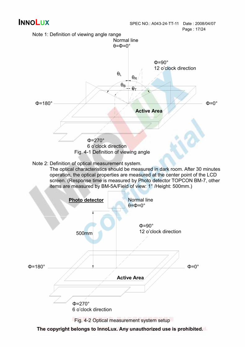
Note 1: Definition of viewing angle range
Fig. 4-1 Definition of viewing angle
Note 2: Definition of optical measurement system. The optical characteristics should be measured in dark room. After 30 minutes
operation, the optical properties are measured at the center point of the LCD screen. (Response time is measured by Photo detector TOPCON BM-7, other items are measured by BM-5A/Field of view: 1° /Height: 500mm.)
Fig. 4-2 Optical measurement system setup
Normal line θ=Φ=0°
Normal line θ=Φ=0°
Photo detector
Φ=90° 12 o’clock direction
Φ=270° 6 o’clock direction
Φ=0° Φ=180°
Active Area
500mm
Φ=90° 12 o’clock direction
Φ=270° 6 o’clock direction
Φ=0° Φ=180°
Active Area
θL
θT
θB
θR
INNOLUX SPEC NO.: A043-24-TT-11 Date : 2008/04/07
Page : 18/24
The copyright belongs to InnoLux. Any unauthorized use is prohibited.
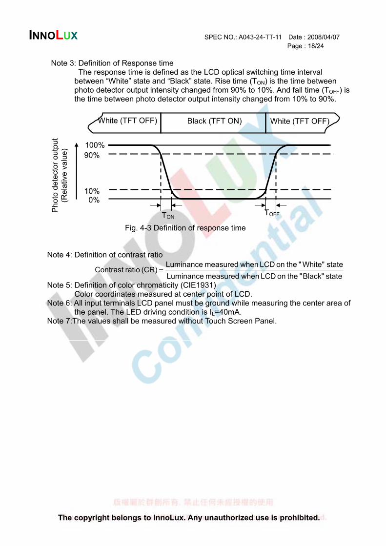
Note 3: Definition of Response time The response time is defined as the LCD optical switching time interval
between “White” state and “Black” state. Rise time (TON) is the time between photo detector output intensity changed from 90% to 10%. And fall time (TOFF) is the time between photo detector output intensity changed from 10% to 90%.
Fig. 4-3 Definition of response time
Note 4: Definition of contrast ratio
state Black"" the on LCD whenmeasured Luminance
state White"" the on LCD whenmeasured Luminance(CR) ratio Contrast =
Note 5: Definition of color chromaticity (CIE1931) Color coordinates measured at center point of LCD.
Note 6: All input terminals LCD panel must be ground while measuring the center area of the panel. The LED driving condition is IL=40mA.
Note 7:The values shall be measured without Touch Screen Panel.
100%
90%
10% 0%
Ph
oto
de
tecto
r o
utp
ut
(Re
lative
va
lue
)
TON TOFF
White (TFT OFF) Black (TFT ON) White (TFT OFF)
INNOLUX SPEC NO.: A043-24-TT-11 Date : 2008/04/07
Page : 19/24
The copyright belongs to InnoLux. Any unauthorized use is prohibited.
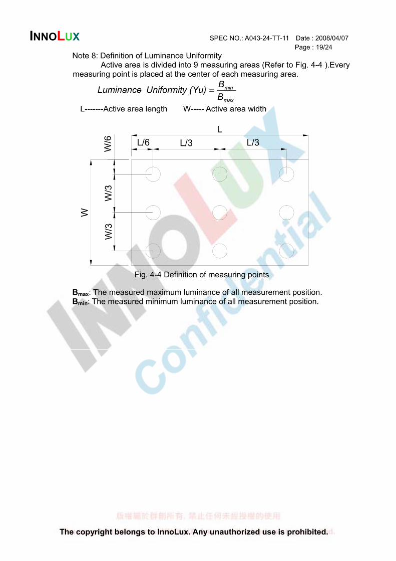
Note 8: Definition of Luminance Uniformity
Active area is divided into 9 measuring areas (Refer to Fig. 4-4 ).Every measuring point is placed at the center of each measuring area.
max
min
B
B(Yu)Uniformity Luminance =
L-------Active area length W----- Active area width
W
W/3
W/3
W/6 L/3L/3L/6
L
Fig. 4-4 Definition of measuring points
Bmax: The measured maximum luminance of all measurement position. Bmin: The measured minimum luminance of all measurement position.
INNOLUX SPEC NO.: A043-24-TT-11 Date : 2008/04/07
Page : 20/24
The copyright belongs to InnoLux. Any unauthorized use is prohibited.
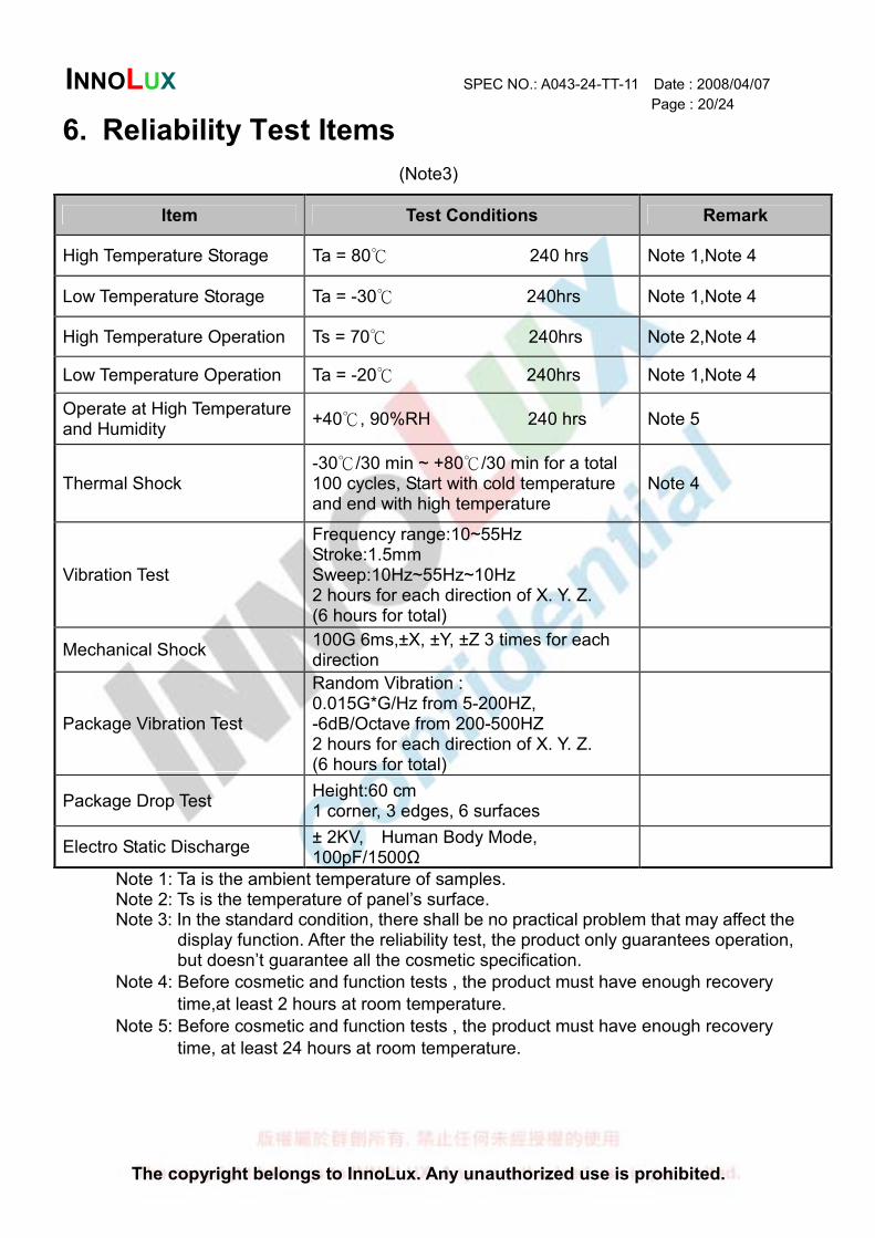
6. Reliability Test Items
(Note3)
Item Test Conditions Remark
High Temperature Storage Ta = 80 240 hrs Note 1,Note 4
Low Temperature Storage Ta = -30 240hrs Note 1,Note 4
High Temperature Operation Ts = 70 240hrs Note 2,Note 4
Low Temperature Operation Ta = -20 240hrs Note 1,Note 4
Operate at High Temperature and Humidity
+40 , 90%RH 240 hrs Note 5
Thermal Shock -30 /30 min ~ + 80 /30 min for a total
100 cycles, Start with cold temperature and end with high temperature
Note 4
Vibration Test
Frequency range:10~55Hz Stroke:1.5mm Sweep:10Hz~55Hz~10Hz 2 hours for each direction of X. Y. Z. (6 hours for total)
Mechanical Shock 100G 6ms,±X, ±Y, ±Z 3 times for each direction
Package Vibration Test
Random Vibration : 0.015G*G/Hz from 5-200HZ, -6dB/Octave from 200-500HZ 2 hours for each direction of X. Y. Z. (6 hours for total)
Package Drop Test Height:60 cm 1 corner, 3 edges, 6 surfaces
Electro Static Discharge ± 2KV, Human Body Mode, 100pF/1500Ω
Note 1: Ta is the ambient temperature of samples. Note 2: Ts is the temperature of panel’s surface.
Note 3: In the standard condition, there shall be no practical problem that may affect the display function. After the reliability test, the product only guarantees operation, but doesn’t guarantee all the cosmetic specification.
Note 4: Before cosmetic and function tests , the product must have enough recovery
time,at least 2 hours at room temperature.
Note 5: Before cosmetic and function tests , the product must have enough recovery
time, at least 24 hours at room temperature.
INNOLUX SPEC NO.: A043-24-TT-11 Date : 2008/04/07
Page : 21/24
The copyright belongs to InnoLux. Any unauthorized use is prohibited.
7. General Precautions
7.1. Safety
Liquid crystal is poisonous. Do not put it in your mouth. If liquid crystal touches your skin or clothes, wash it off immediately by using soap and water.
7.2. Handling
1. The LCD panel is plate glass. Do not subject the panel to mechanical shock or to excessive force on its surface.
2. The polarizer attached to the display is easily damaged. Please handle it carefully to avoid scratch or other damages.
3. To avoid contamination on the display surface, do not touch the module surface with bare hands.
4. Keep a space so that the LCD panels do not touch other components. 5. Put cover board such as acrylic board on the surface of LCD panel to protect
panel from damages. 6. Transparent electrodes may be disconnected if you use the LCD panel under
environmental conditions where the condensation of dew occurs. 7. Do not leave module in direct sunlight to avoid malfunction of the ICs.
7.3. Static Electricity
1. Be sure to ground module before turning on power or operating module. 2. Do not apply voltage which exceeds the absolute maximum rating value.
7.4. Storage
1. Store the module in a dark room where must keep at 25±10 and 65%RH or less.
2. Do not store the module in surroundings containing organic solvent or corrosive gas.
3. Store the module in an anti-electrostatic container or bag.
7.5. Cleaning
1. Do not wipe the polarizer with dry cloth. It might cause scratch. 2. Only use a soft sloth with IPA to wipe the polarizer, other chemicals might
permanent damage to the polarizer.
INNOLUX SPEC NO.: A043-24-TT-11 Date : 2008/04/07
Page : 22/24
The copyright belongs to InnoLux. Any unauthorized use is prohibited.
8. Mechanical Drawing
INNOLUX SPEC NO.: A043-24-TT-11 Date : 2008/04/07
Page : 23/24
The copyright belongs to InnoLux. Any unauthorized use is prohibited.
9. Package Drawing
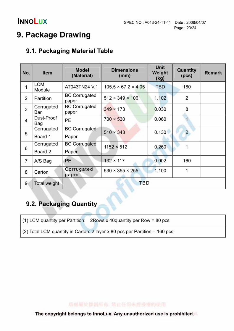
9.1. Packaging Material Table
No. Item Model
(Material) Dimensions
(mm)
Unit Weight (kg)
Quantity (pcs)
Remark
1 LCM Module
AT043TN24 V.1 105.5 × 67.2 × 4.05 TBD 160
2 Partition BC Corrugated paper
512 × 349 × 106 1.102 2
3 Corrugated Bar
BC Corrugated paper
349 × 173 0.030 8
4 Dust-Proof Bag
PE 700 × 530 0.060 1
5 Corrugated
Board-1
BC Corrugated
Paper 510 × 343 0.130 2
6 Corrugated
Board-2
BC Corrugated
Paper 1152 × 512 0.260 1
7 A/S Bag PE 132 × 117 0.002 160
8 Carton Corrugated paper
530 × 355 × 255 1.100 1
9 Total weight TBD
9.2. Packaging Quantity
(1) LCM quantity per Partition: 2Rows x 40quantity per Row = 80 pcs
(2) Total LCM quantity in Carton: 2 layer x 80 pcs per Partition = 160 pcs
INNOLUX SPEC NO.: A043-24-TT-11 Date : 2008/04/07
Page : 24/24
The copyright belongs to InnoLux. Any unauthorized use is prohibited.
9.3. Packaging Drawing
TBD