Embed Size (px)
Citation preview
µLCD-144-G2(GFX)4DGL Platform LCD Display ModuleData Sheet
Document Date: 18th April 2012Document Revision: 1.0
© 2012 4D Systems www.4dsystems.com.au Page 1 of 18
µLCD-144-G2(GFX)4DGL LCD Display Module
Data Sheet
Description
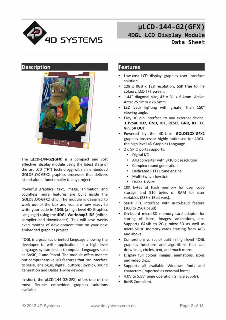
The µLCD-144-G2(GFX) is a compact and cost effective display module using the latest state of the art LCD (TFT) technology with an embedded GOLDELOX-GFX2 graphics processor that delivers ‘stand-alone’ functionality to any project.
Powerful graphics, text, image, animation and countless more features are built inside the GOLDELOX-GFX2 chip. The module is designed to work out of the box and you are now ready to write your code in 4DGL (a high level 4D Graphics Language) using the 4DGL-Workshop3 IDE (editor, compiler and downloader). This will save weeks even months of development time on your next embedded graphics project.
4DGL is a graphics oriented language allowing the developer to write applications in a high level language, syntax similar to popular languages such as BASIC, C and Pascal. The module offers modest but comprehensive I/O features that can interface to serial, analogue, digital, buttons, joystick, sound generation and Dallas 1-wire devices.
In short, the µLCD-144-G2(GFX) offers one of the most flexible embedded graphics solutions available.
Features• Low-cost LCD display graphics user interface
solution.• 128 x RGB x 128 resolution, 65K true to life
colours, LCD TFT screen.• 1.44” diagonal size, 43 x 31 x 6.4mm. Active
Area: 25.5mm x 26.5mm.• LED back lighting with greater than 150°
viewing angle.• Easy 10 pin interface to any external device:
3.3Vout, IO2, GND, IO1, RESET, GND, RX, TX, Vin, 5V OUT.
• Powered by the 4D-Labs GOLDELOX-GFX2 graphics processor highly optimised for 4DGL, the high level 4D Graphics Language.
• 2 x GPIO ports supports:• Digital I/O• A/D converter with 8/10 bit resolution• Complex sound generation• Dedicated RTTTL tune engine• Multi-Switch Joystick• Dallas 1-Wire
• 10K bytes of flash memory for user code storage and 510 bytes of RAM for user variables (255 x 16bit vars).
• Serial TTL interface with auto-baud feature (300 to 256K baud).
• On-board micro-SD memory card adaptor for storing of icons, images, animations, etc. Supports 64Mb to 2Gig micro-SD as well as micro-SDHC memory cards starting from 4GB and above.
• Comprehensive set of built in high level 4DGL graphics functions and algorithms that can draw lines, circles, text, and much more.
• Display full colour images, animations, icons and video clips.
• Supports all available Windows fonts and characters (imported as external fonts).
• 4.0V to 5.5V range operation (single supply).• RoHS Compliant.
© 2012 4D Systems www.4dsystems.com.au Page 2 of 18
µLCD-144-G2(GFX) Data Sheet
Table of Contents1. Pin Configuration and Summary.............................................................................................................42. Hardware Platform.................................................................................................................................5
2.1 Serial Interface - UART ..........................................................................................................................52.2 General Purpose I/O Interface...............................................................................................................52.3 System Pins............................................................................................................................................7
3. Software Platform - 4DGL.......................................................................................................................74. Module Features...................................................................................................................................10
4.1 The Display – 1.44” LCD TFT.................................................................................................................104.2 The GOLDELOX-GFX2 Processor...........................................................................................................104.3 The uSD/uSDHC Memory Card............................................................................................................10
5. Programming - System Updates............................................................................................................116. LCD Screen Precaution..........................................................................................................................117. Development and Support Tools...........................................................................................................12
7.1 PmmC Loader – Software Programming Tool ......................................................................................127.2 microUSB – Hardware Programming Tool............................................................................................127.3 FONT Tool – Software Tool...................................................................................................................127.4 Graphics Composer – Software Tool....................................................................................................127.5 Development Board.............................................................................................................................137.6 4DGL-Workshop3 – Complete IDE Editor, Compiler, Linker, Downloader............................................13
8. Mechanical Dimensions........................................................................................................................149. Reference Design..................................................................................................................................1510. Specifications and Ratings..................................................................................................................16Proprietary Information............................................................................................................................18Disclaimer of Warranties & Limitation of Liability.....................................................................................18
© 2012 4D Systems www.4dsystems.com.au Page 3 of 18
µLCD-144-G2(GFX) Data Sheet
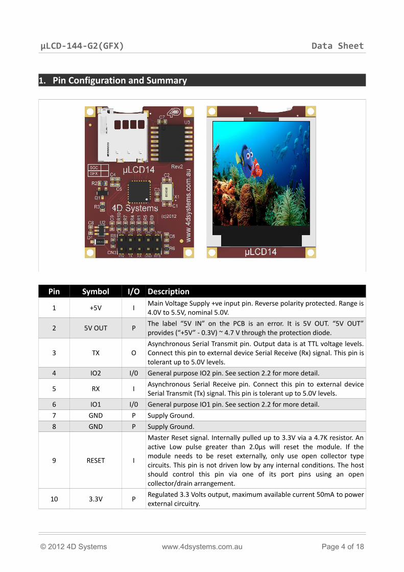
1. Pin Configuration and Summary
Pin Symbol I/O Description
1 +5V I Main Voltage Supply +ve input pin. Reverse polarity protected. Range is 4.0V to 5.5V, nominal 5.0V.
2 5V OUT P The label “5V IN” on the PCB is an error. It is 5V OUT. “5V OUT” provides (“+5V” - 0.3V) ~ 4.7 V through the protection diode.
3 TX OAsynchronous Serial Transmit pin. Output data is at TTL voltage levels. Connect this pin to external device Serial Receive (Rx) signal. This pin is tolerant up to 5.0V levels.
4 IO2 I/0 General purpose IO2 pin. See section 2.2 for more detail.
5 RX I Asynchronous Serial Receive pin. Connect this pin to external device Serial Transmit (Tx) signal. This pin is tolerant up to 5.0V levels.
6 IO1 I/0 General purpose IO1 pin. See section 2.2 for more detail.7 GND P Supply Ground.8 GND P Supply Ground.
9 RESET I
Master Reset signal. Internally pulled up to 3.3V via a 4.7K resistor. An active Low pulse greater than 2.0μs will reset the module. If the module needs to be reset externally, only use open collector type circuits. This pin is not driven low by any internal conditions. The host should control this pin via one of its port pins using an open collector/drain arrangement.
10 3.3V P Regulated 3.3 Volts output, maximum available current 50mA to power external circuitry.
© 2012 4D Systems www.4dsystems.com.au Page 4 of 18
µLCD-144-G2(GFX) Data Sheet
2. Hardware PlatformThe µLCD-144-G2(GFX) provides both a hardware and a software platform. This section describes in detail the hardware platform, namely the user interface pins.
2.1 Serial Interface - UART The µLCD-144-G2(GFX) has a dedicated hardware UART that can communicate with external serial devices.
The primary features are:• Full-Duplex 8 bit data transmission and
reception through the TX and RX pins.• Data format: 8 bits, No Parity, 1 Stop bit. • Auto Baud feature.• Baud rates from 300 baud up to 256K baud.
The Serial port is also the primary interface for downloading compiled 4DGL application code as well as future PmmC updates for the on-board GOLDELOX-GFX2 processor. Refer to Section 5. Programming-System Updates for more details.
TX pin 3 (Serial Transmit):Asynchronous Serial port Transmit pin, TX. The serial output data is at TTL voltage levels. Connect this pin to external serial device Rx signal.
RX pin 5 (Serial Receive):Asynchronous Serial port Receive pin, RX. Connect this pin to external serial device Transmit Tx signal.
2.2 General Purpose I/O InterfaceThere are 2 GPIO pins available, IO1 and IO2. Each GPIO has a multitude of high level functions associated with it and these can be selected within 4DGL user application code. Refer to the separate document titled “GOLDELOX-GFX2-Internal-Functions.pdf” for a complete set of built in 4DGL library functions.
IO1 pin 6 (General Purpose IO1):General purpose IO1 pin. The table below lists the available GPIO functions and features.
IO2 pin 4 (General Purpose IO2):General purpose IO2 pin. The table below lists the available GPIO functions and features.
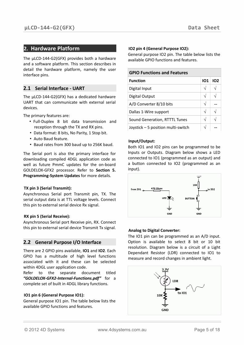
GPIO Functions and Features
Function IO1 IO2
Digital Input √ √
Digital Output √ √
A/D Converter 8/10 bits √ --
Dallas 1-Wire support √ √
Sound Generation, RTTTL Tunes √ √
Joystick – 5 position multi-switch √ --
Input/Output:Both IO1 and IO2 pins can be programmed to be Inputs or Outputs. Diagram below shows a LED connected to IO1 (programmed as an output) and a button connected to IO2 (programmed as an input).
Analog to Digital Converter:The IO1 pin can be programmed as an A/D input. Option is available to select 8 bit or 10 bit resolution. Diagram below is a circuit of a Light Dependant Resistor (LDR) connected to IO1 to measure and record changes in ambient light.
© 2012 4D Systems www.4dsystems.com.au Page 5 of 18
µLCD-144-G2(GFX) Data Sheet
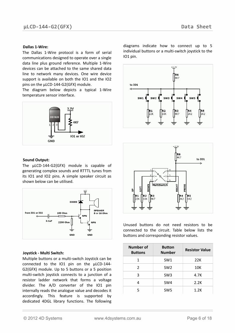
Dallas 1-Wire:The Dallas 1-Wire protocol is a form of serial communications designed to operate over a single data line plus ground reference. Multiple 1-Wire devices can be attached to the same shared data line to network many devices. One wire device support is available on both the IO1 and the IO2 pins on the µLCD-144-G2(GFX) module. The diagram below depicts a typical 1-Wire temperature sensor interface.
Sound Output:The µLCD-144-G2(GFX) module is capable of generating complex sounds and RTTTL tunes from its IO1 and IO2 pins. A simple speaker circuit as shown below can be utilised.
Joystick - Multi Switch:Multiple buttons or a multi-switch Joystick can be connected to the IO1 pin on the µLCD-144-G2(GFX) module. Up to 5 buttons or a 5 position multi-switch joystick connects to a junction of a resistor ladder network that forms a voltage divider. The A/D converter of the IO1 pin internally reads the analogue value and decodes it accordingly. This feature is supported by dedicated 4DGL library functions. The following
diagrams indicate how to connect up to 5 individual buttons or a multi-switch joystick to the IO1 pin.
Unused buttons do not need resistors to be connected to the circuit. Table below lists the buttons and corresponding resistor values.
Number of Buttons
Button Number Resistor Value
1 SW1 22K
2 SW2 10K
3 SW3 4.7K
4 SW4 2.2K
5 SW5 1.2K
© 2012 4D Systems www.4dsystems.com.au Page 6 of 18
µLCD-144-G2(GFX) Data Sheet
2.3 System Pins
+5V pin 1 (Module Supply Voltage Input):Module supply voltage input pin. This pin must be connected to a regulated supply voltage in the range of 4.0 Volts to 5.5 Volts DC. Nominal operating voltage is 5.0 Volts.
5V OUT pin 2 (~ 4.7V Output):External circuitry that requires approximately 5V supply can be powered up via this pin. Maximum available current is 50mA.
Note: Pin 2 is labelled “5V IN” by mistake. It is 5V OUT. This pin provides (“+5V” - 0.3V) ~ 4.7 V through the protection diode.
3.3Vout pin 10 (3.3V Regulated Output):External circuitry that requires a regulated 3.3V supply can be powered up via this pin. Maximum available current is 50mA.
GND pins 7,8 (Module Ground):Module ground pins. These pins must be connected to ground.
RESET pin 9 (Module Master Reset):Module Master Reset pin. An active low pulse of greater than 2 micro-seconds will reset the module. Internally pulled up to 3.3V via 4.7K resistor. Only use open collector type circuits to reset the device if an external reset is required.
3. Software Platform - 4DGL
The heart of the µLCD-144-G2(GFX) module is the GOLDELOX-GFX2 graphics processor from 4D Labs. The GOLDELOX-GFX2 belongs to a family of processors powered by a highly optimised soft core virtual engine, E.V.E. (Extensible Virtual Engine).
EVE is a proprietary, high performance virtual processor with an extensive byte-code instruction set optimised to execute compiled 4DGL programs. 4DGL (4D Graphics Language) was specifically developed from ground up for the EVE engine core. It is a high level language which is easy to learn and simple to understand yet powerful enough to tackle many embedded graphics applications.
4DGL is a graphics oriented language allowing rapid application development and the syntax structure was designed using elements of popular languages such as C, Basic, Pascal and others. Programmers familiar with these languages will feel right at home with 4DGL. It includes many familiar instructions such as IF..ELSE..ENDIF, WHILE..WEND, REPEAT..UNTIL, GOTO, PRINT as well as some specialised instructions SERIN, SEROUT, GFX_LINE, GFX_CIRCLE and many more. This section only covers the syntax of the available instructions and functions. For a more in depth study refer to the following documents:“4DGL-Programmers-Reference-Manual.pdf” and “GOLDELOX-GFX2-4DGL-Internal-Functions.pdf”
The following is a brief outline of 4DGL instructions and functions available for the µLCD-144-G2(GFX) module:
Generic 4DGL Instructions:• if..else..endif• while..wend• repeat..until/forever• gosub..endsub• func..endfunc• goto• for/next• switch/case
© 2012 4D Systems www.4dsystems.com.au Page 7 of 18
µLCD-144-G2(GFX) Data Sheet
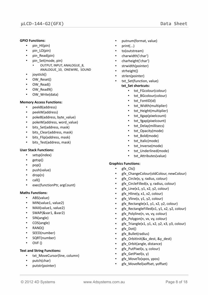
GPIO Functions:• pin_HI(pin)• pin_LO(pin)• pin_Read(pin)• pin_Set(mode, pin)
• OUTPUT, INPUT, ANALOGUE_8, ANALOGUE_10, ONEWIRE, SOUND
• joystick()• OW_Reset()• OW_Read()• OW_Read9()• OW_Write(data)
Memory Access Functions:• peekB(address)• peekW(address)• pokeB(address, byte_value)• pokeW(address, word_value)• bits_Set(address, mask)• bits_Clear(address, mask)• bits_Flip(address, mask)• bits_Test(address, mask)
User Stack Functions:• setsp(index)• getsp()• pop()• push(value)• drop(n)• call()• exec(functionPtr, argCount)
Maths Functions:• ABS(value)• MIN(value1, value2)• MAX(value1, value2)• SWAP(&var1, &var2)• SIN(angle)• COS(angle)• RAND()• SEED(number)• SQRT(number)• OVF ()
Text and String Functions:• txt_MoveCursor(line, column)• putch(char)• putstr(pointer)
• putnum(format, value)• print(...)• to(outstream)• charwidth('char')• charheight('char')• strwidth(pointer)• strheight()• strlen(pointer)• txt_Set(function, value)
txt_Set shortcuts:• txt_FGcolour(colour)• txt_BGcolour(colour)• txt_FontID(id)• txt_Width(multiplier)• txt_Height(multiplier)• txt_Xgap(pixelcount)• txt_Ygap(pixelcount)• txt_Delay(millisecs)• txt_Opacity(mode)• txt_Bold(mode)• txt_Italic(mode)• txt_Inverse(mode)• txt_Underlined(mode)• txt_Attributes(value)
Graphics Functions:• gfx_Cls()• gfx_ChangeColour(oldColour, newColour)• gfx_Circle(x, y, radius, colour)• gfx_CircleFilled(x, y, radius, colour)• gfx_Line(x1, y1, x2, y2, colour)• gfx_Hline(y, x1, x2, colour)• gfx_Vline(x, y1, y2, colour)• gfx_Rectangle(x1, y1, x2, y2, colour)• gfx_RectangleFilled(x1, y1, x2, y2, colour)• gfx_Polyline(n, vx, vy, colour)• gfx_Polygon(n, vx, vy, colour)• gfx_Triangle(x1, y1, x2, y2, x3, y3, colour)• gfx_Dot()• gfx_Bullet(radius)• gfx_OrbitInit(&x_dest, &y_dest)• gfx_Orbit(angle, distance)• gfx_PutPixel(x, y, colour)• gfx_GetPixel(x, y)• gfx_MoveTo(xpos, ypos)• gfx_MoveRel(xoffset, yoffset)
© 2012 4D Systems www.4dsystems.com.au Page 8 of 18
µLCD-144-G2(GFX) Data Sheet
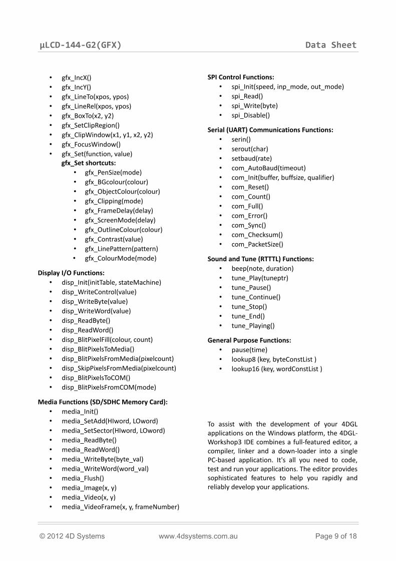
• gfx_IncX()• gfx_IncY()• gfx_LineTo(xpos, ypos)• gfx_LineRel(xpos, ypos)• gfx_BoxTo(x2, y2)• gfx_SetClipRegion()• gfx_ClipWindow(x1, y1, x2, y2)• gfx_FocusWindow()• gfx_Set(function, value)
gfx_Set shortcuts:• gfx_PenSize(mode)• gfx_BGcolour(colour)• gfx_ObjectColour(colour)• gfx_Clipping(mode)• gfx_FrameDelay(delay)• gfx_ScreenMode(delay)• gfx_OutlineColour(colour)• gfx_Contrast(value)• gfx_LinePattern(pattern)• gfx_ColourMode(mode)
Display I/O Functions:• disp_Init(initTable, stateMachine)• disp_WriteControl(value)• disp_WriteByte(value)• disp_WriteWord(value)• disp_ReadByte()• disp_ReadWord()• disp_BlitPixelFill(colour, count)• disp_BlitPixelsToMedia()• disp_BlitPixelsFromMedia(pixelcount) • disp_SkipPixelsFromMedia(pixelcount)• disp_BlitPixelsToCOM()• disp_BlitPixelsFromCOM(mode)
Media Functions (SD/SDHC Memory Card):• media_Init()• media_SetAdd(HIword, LOword)• media_SetSector(HIword, LOword)• media_ReadByte()• media_ReadWord()• media_WriteByte(byte_val)• media_WriteWord(word_val)• media_Flush()• media_Image(x, y)• media_Video(x, y)• media_VideoFrame(x, y, frameNumber)
SPI Control Functions:• spi_Init(speed, inp_mode, out_mode)• spi_Read()• spi_Write(byte)• spi_Disable()
Serial (UART) Communications Functions:• serin()• serout(char)• setbaud(rate)• com_AutoBaud(timeout)• com_Init(buffer, buffsize, qualifier)• com_Reset()• com_Count()• com_Full()• com_Error()• com_Sync()• com_Checksum()• com_PacketSize()
Sound and Tune (RTTTL) Functions:• beep(note, duration)• tune_Play(tuneptr)• tune_Pause()• tune_Continue()• tune_Stop()• tune_End()• tune_Playing()
General Purpose Functions:• pause(time)• lookup8 (key, byteConstList )• lookup16 (key, wordConstList )
To assist with the development of your 4DGL applications on the Windows platform, the 4DGL- Workshop3 IDE combines a full-featured editor, a compiler, linker and a down-loader into a single PC-based application. It's all you need to code, test and run your applications. The editor provides sophisticated features to help you rapidly and reliably develop your applications.
© 2012 4D Systems www.4dsystems.com.au Page 9 of 18
µLCD-144-G2(GFX) Data Sheet
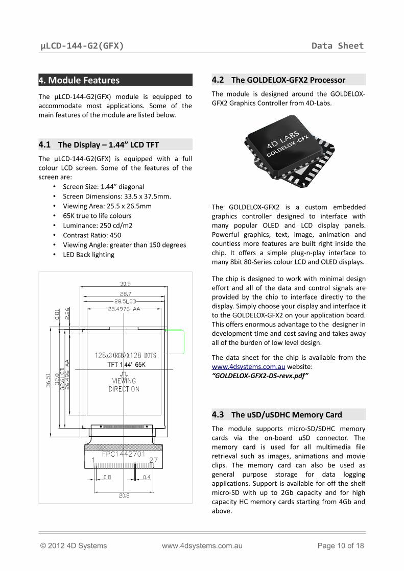
4. Module FeaturesThe µLCD-144-G2(GFX) module is equipped to accommodate most applications. Some of the main features of the module are listed below.
4.1 The Display – 1.44” LCD TFTThe µLCD-144-G2(GFX) is equipped with a full colour LCD screen. Some of the features of the screen are:
• Screen Size: 1.44” diagonal• Screen Dimensions: 33.5 x 37.5mm. • Viewing Area: 25.5 x 26.5mm• 65K true to life colours• Luminance: 250 cd/m2 • Contrast Ratio: 450• Viewing Angle: greater than 150 degrees • LED Back lighting
4.2 The GOLDELOX-GFX2 ProcessorThe module is designed around the GOLDELOX-GFX2 Graphics Controller from 4D-Labs.
The GOLDELOX-GFX2 is a custom embedded graphics controller designed to interface with many popular OLED and LCD display panels. Powerful graphics, text, image, animation and countless more features are built right inside the chip. It offers a simple plug-n-play interface to many 8bit 80-Series colour LCD and OLED displays.
The chip is designed to work with minimal design effort and all of the data and control signals are provided by the chip to interface directly to the display. Simply choose your display and interface it to the GOLDELOX-GFX2 on your application board. This offers enormous advantage to the designer in development time and cost saving and takes away all of the burden of low level design.
The data sheet for the chip is available from the www.4dsystems.com.au website:“GOLDELOX-GFX2-DS-revx.pdf”
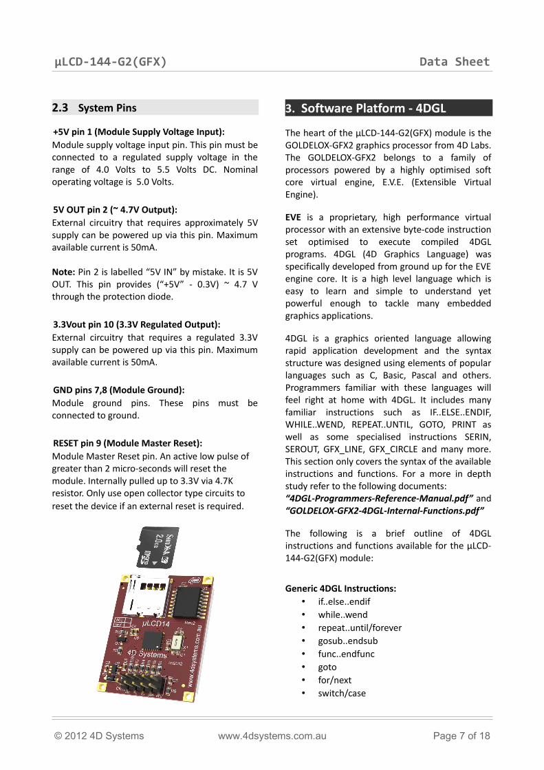
4.3 The uSD/uSDHC Memory CardThe module supports micro-SD/SDHC memory cards via the on-board uSD connector. The memory card is used for all multimedia file retrieval such as images, animations and movie clips. The memory card can also be used as general purpose storage for data logging applications. Support is available for off the shelf micro-SD with up to 2Gb capacity and for high capacity HC memory cards starting from 4Gb and above.
© 2012 4D Systems www.4dsystems.com.au Page 10 of 18
µLCD-144-G2(GFX) Data Sheet
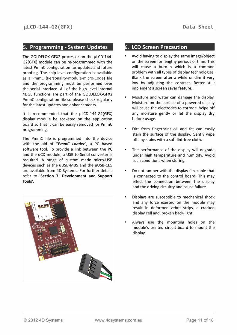
5. Programming - System UpdatesThe GOLDELOX-GFX2 processor on the µLCD-144-G2(GFX) module can be re-programmed with the latest PmmC configuration for updates and future proofing. The chip-level configuration is available as a PmmC (Personality-module-micro-Code) file and the programming must be performed over the serial interface. All of the high level internal 4DGL functions are part of the GOLDELOX-GFX2 PmmC configuration file so please check regularly for the latest updates and enhancements.
It is recommended that the µLCD-144-G2(GFX) display module be socketed on the application board so that it can be easily removed for PmmC programming.
The PmmC file is programmed into the device with the aid of “PmmC Loader”, a PC based software tool. To provide a link between the PC and the uCD module, a USB to Serial converter is required. A range of custom made micro-USB devices such as the uUSB-MB5 and the uUSB-CE5 are available from 4D Systems. For further details refer to 'Section 7: Development and Support Tools'.
6. LCD Screen Precaution• Avoid having to display the same image/object
on the screen for lengthy periods of time. This will cause a burn-in which is a common problem with all types of display technologies. Blank the screen after a while or dim it very low by adjusting the contrast. Better still; implement a screen saver feature.
• Moisture and water can damage the display. Moisture on the surface of a powered display will cause the electrodes to corrode. Wipe off any moisture gently or let the display dry before usage.
• Dirt from fingerprint oil and fat can easily stain the surface of the display. Gently wipe off any stains with a soft lint-free cloth.
• The performance of the display will degrade under high temperature and humidity. Avoid such conditions when storing.
• Do not tamper with the display flex cable that is connected to the control board. This may effect the connection between the display and the driving circuitry and cause failure.
• Displays are susceptible to mechanical shock and any force exerted on the module may result in deformed zebra strips, a cracked display cell and broken back-light
• Always use the mounting holes on the module's printed circuit board to mount the display.
© 2012 4D Systems www.4dsystems.com.au Page 11 of 18
µLCD-144-G2(GFX) Data Sheet
7. Development and Support Tools
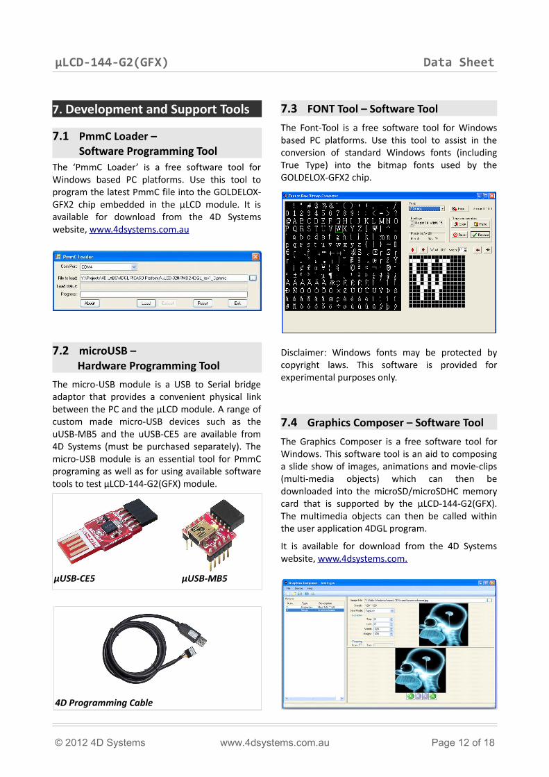
7.1 PmmC Loader – Software Programming Tool
The ‘PmmC Loader’ is a free software tool for Windows based PC platforms. Use this tool to program the latest PmmC file into the GOLDELOX-GFX2 chip embedded in the μLCD module. It is available for download from the 4D Systems website, www.4dsystems.com.au
7.2 microUSB – Hardware Programming Tool
The micro-USB module is a USB to Serial bridge adaptor that provides a convenient physical link between the PC and the μLCD module. A range of custom made micro-USB devices such as the uUSB-MB5 and the uUSB-CE5 are available from 4D Systems (must be purchased separately). The micro-USB module is an essential tool for PmmC programing as well as for using available software tools to test µLCD-144-G2(GFX) module.
7.3 FONT Tool – Software ToolThe Font-Tool is a free software tool for Windows based PC platforms. Use this tool to assist in the conversion of standard Windows fonts (including True Type) into the bitmap fonts used by the GOLDELOX-GFX2 chip.
Disclaimer: Windows fonts may be protected by copyright laws. This software is provided for experimental purposes only.
7.4 Graphics Composer – Software ToolThe Graphics Composer is a free software tool for Windows. This software tool is an aid to composing a slide show of images, animations and movie-clips (multi-media objects) which can then be downloaded into the microSD/microSDHC memory card that is supported by the µLCD-144-G2(GFX). The multimedia objects can then be called within the user application 4DGL program.
It is available for download from the 4D Systems website, www.4dsystems.com.
© 2012 4D Systems www.4dsystems.com.au Page 12 of 18
4D Programming Cable
μUSB-CE5 μUSB-MB5
µLCD-144-G2(GFX) Data Sheet
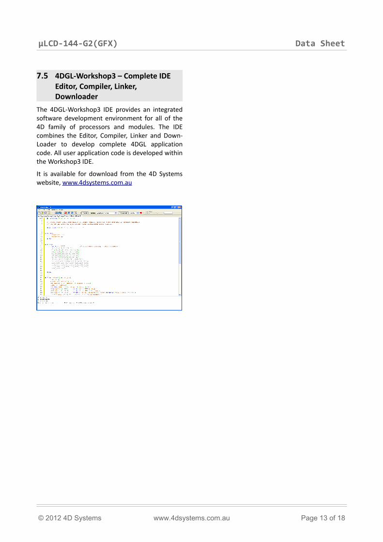
7.5 4DGL-Workshop3 – Complete IDE Editor, Compiler, Linker, Downloader
The 4DGL-Workshop3 IDE provides an integrated software development environment for all of the 4D family of processors and modules. The IDE combines the Editor, Compiler, Linker and Down-Loader to develop complete 4DGL application code. All user application code is developed within the Workshop3 IDE.
It is available for download from the 4D Systems website, www.4dsystems.com.au
© 2012 4D Systems www.4dsystems.com.au Page 13 of 18
µLCD-144-G2(GFX) Data Sheet
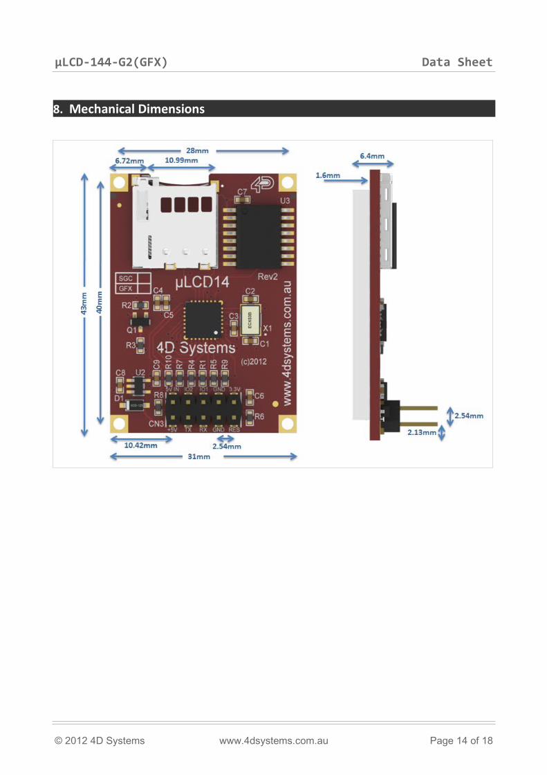
8. Mechanical Dimensions
© 2012 4D Systems www.4dsystems.com.au Page 14 of 18
µLCD-144-G2(GFX) Data Sheet
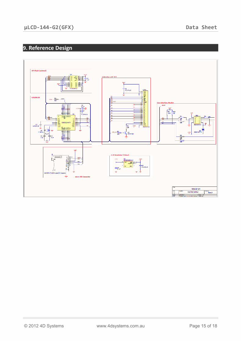
9. Reference Design
© 2012 4D Systems www.4dsystems.com.au Page 15 of 18
µLCD-144-G2(GFX) Data Sheet
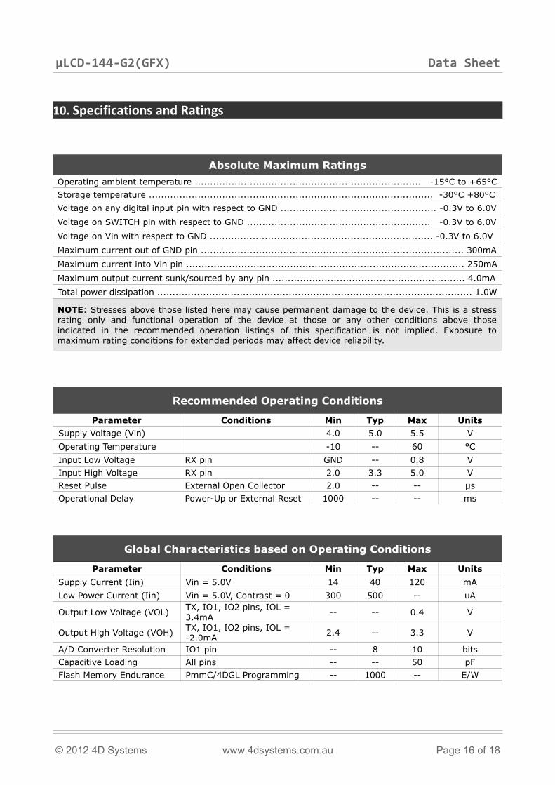
10. Specifications and Ratings
Absolute Maximum RatingsOperating ambient temperature .......................................................................... -15°C to +65°CStorage temperature ............................................................................................. -30°C +80°CVoltage on any digital input pin with respect to GND ................................................... -0.3V to 6.0VVoltage on SWITCH pin with respect to GND ............................................................ -0.3V to 6.0VVoltage on Vin with respect to GND ......................................................................... -0.3V to 6.0VMaximum current out of GND pin ...................................................................................... 300mAMaximum current into Vin pin ........................................................................................... 250mAMaximum output current sunk/sourced by any pin ............................................................... 4.0mATotal power dissipation ....................................................................................................... 1.0W
NOTE: Stresses above those listed here may cause permanent damage to the device. This is a stress rating only and functional operation of the device at those or any other conditions above those indicated in the recommended operation listings of this specification is not implied. Exposure to maximum rating conditions for extended periods may affect device reliability.
Recommended Operating Conditions
Parameter Conditions Min Typ Max UnitsSupply Voltage (Vin) 4.0 5.0 5.5 VOperating Temperature -10 -- 60 °CInput Low Voltage RX pin GND -- 0.8 VInput High Voltage RX pin 2.0 3.3 5.0 VReset Pulse External Open Collector 2.0 -- -- µsOperational Delay Power-Up or External Reset 1000 -- -- ms
Global Characteristics based on Operating Conditions
Parameter Conditions Min Typ Max UnitsSupply Current (Iin) Vin = 5.0V 14 40 120 mALow Power Current (Iin) Vin = 5.0V, Contrast = 0 300 500 -- uA
Output Low Voltage (VOL) TX, IO1, IO2 pins, IOL = 3.4mA -- -- 0.4 V
Output High Voltage (VOH) TX, IO1, IO2 pins, IOL = -2.0mA 2.4 -- 3.3 V
A/D Converter Resolution IO1 pin -- 8 10 bitsCapacitive Loading All pins -- -- 50 pFFlash Memory Endurance PmmC/4DGL Programming -- 1000 -- E/W
© 2012 4D Systems www.4dsystems.com.au Page 16 of 18
µLCD-144-G2(GFX) Data Sheet
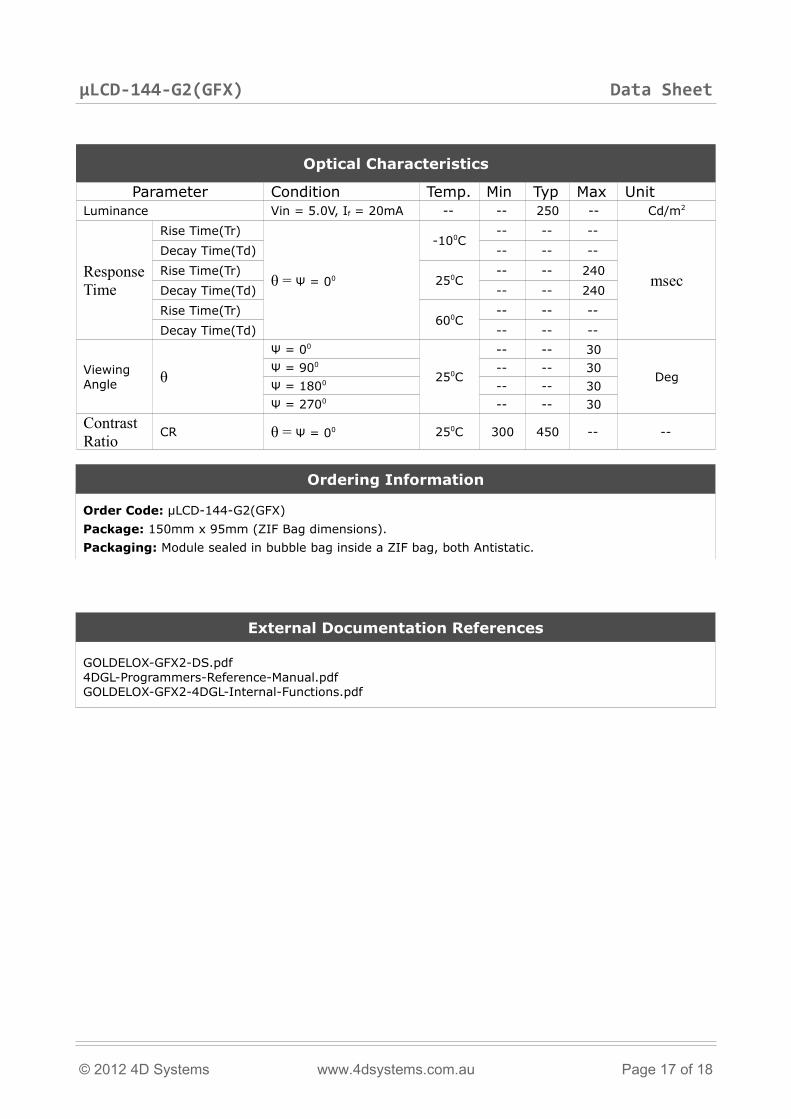
Optical Characteristics
Parameter Condition Temp. Min Typ Max UnitLuminance Vin = 5.0V, If = 20mA -- -- 250 -- Cd/m2
Response Time
Rise Time(Tr)
θ = Ψ = 00
-100C-- -- --
msec
Decay Time(Td) -- -- --Rise Time(Tr)
250C-- -- 240
Decay Time(Td) -- -- 240Rise Time(Tr)
600C-- -- --
Decay Time(Td) -- -- --
Viewing Angle θ
Ψ = 00
250C
-- -- 30
DegΨ = 900 -- -- 30Ψ = 1800 -- -- 30Ψ = 2700 -- -- 30
Contrast Ratio CR θ = Ψ = 00 250C 300 450 -- --
Ordering Information
Order Code: µLCD-144-G2(GFX)Package: 150mm x 95mm (ZIF Bag dimensions).Packaging: Module sealed in bubble bag inside a ZIF bag, both Antistatic.
External Documentation References
GOLDELOX-GFX2-DS.pdf4DGL-Programmers-Reference-Manual.pdfGOLDELOX-GFX2-4DGL-Internal-Functions.pdf
© 2012 4D Systems www.4dsystems.com.au Page 17 of 18
µLCD-144-G2(GFX) Data Sheet
Proprietary Information
The information contained in this document is the property of 4D Systems Pty. Ltd. and may be the subject of patents pending or granted, and must not be copied or disclosed with out prior written permission.
4D Systems endeavours to ensure that the information in this document is correct and fairly stated but does not accept liability for any error or omission. The development of 4D Systems products and services is continuous and published information may not be up to date. It is important to check the current position with 4D Systems. 4D Systems reserves the right to modify, update or make changes to Specifications or written material without prior notice at any time.
All trademarks belong to their respective owners and are recognised and acknowledged.
Disclaimer of Warranties & Limitation of Liability
4D Systems makes no warranty, either express or implied with respect to any product, and specifically disclaims all other warranties, including, without limitation, warranties for merchantability, non-infringement and fitness for any particular purpose.
Information contained in this publication regarding device applications and the like is provided only for your convenience and may be superseded by updates. It is your responsibility to ensure that your application meets with your specifications.
In no event shall 4D Systems be liable to the buyer or to any third party for any indirect, incidental, special, consequential, punitive or exemplary damages (including without limitation lost profits, lost savings, or loss of business opportunity) arising out of or relating to any product or service provided or to be provided by 4D Systems, or the use or inability to use the same, even if 4D Systems has been advised of the possibility of such damages.
4D Systems products are not fault tolerant nor designed, manufactured or intended for use or resale as on line control equipment in hazardous environments requiring fail – safe performance, such as in the operation of nuclear facilities, aircraft navigation or communication systems, air traffic control, direct life support machines or weapons systems in which the failure of the product could lead directly to death, personal injury or severe physical or environmental damage (‘High Risk Activities’). 4D Systems and its suppliers specifically disclaim any expressed or implied warranty of fitness for High Risk Activities.
Use of 4D Systems’ products and devices in 'High Risk Activities' and in any other application is entirely at the buyer’s risk, and the buyer agrees to defend, indemnify and hold harmless 4D Systems from any and all damages, claims, suits, or expenses resulting from such use. No licenses are conveyed, implicitly or otherwise, under any 4D Systems intellectual property rights.
Contact InformationFor Technical Support : [email protected]
For Sales Support : [email protected]
Website : www.4dsystems.com.au
Copyright 4D Systems Pty. Ltd. 2000-2012.
© 2012 4D Systems www.4dsystems.com.au Page 18 of 18